group 42 body - evoscan · 2010-08-22 · hood 42-4 body hood on-vehicle service adjustment of...
TRANSCRIPT

GROUP 42
BODYCONTENTS
HOOD. . . . . . . . . . . . . . . . . . . . . 42-4
ON-VEHICLE SERVICE. . . . . . . . . 42-4ADJUSTMENT OF CLEARANCE AROUND HOOD . . . . . . . . . . . . . . . . . . 42-4ADJUSTMENT OF ALIGNMENT OF HOOD STEPPED PORTION AND HOOD STRIKER . . . . . . . . . . . . . . . . . . 42-4ADJUSTMENT OF HOOD HEIGHT . . . 42-4
HOOD. . . . . . . . . . . . . . . . . . . . . . . 42-5REMOVAL AND INSTALLATION . . . . . 42-5
FENDER. . . . . . . . . . . . . . . . . . . 42-7
SPECIAL TOOL. . . . . . . . . . . . . . . 42-7
FENDER. . . . . . . . . . . . . . . . . . . . . 42-7REMOVAL AND INSTALLATION . . . . . 42-7
FUEL FILLER LID . . . . . . . . . . . 42-10
REMOVAL AND INSTALLATION . . . . . . . . . . . . . . . 42-10
STRUT TOWER BAR <4G1> . . 42-11
REMOVAL AND INSTALLATION . . . . . . . . . . . . . . . 42-11
PROTECTOR FILM . . . . . . . . . 42-12
REMOVAL AND INSTALLATION . . . . . . . . . . . . . . . 42-12
WINDOW GLASS. . . . . . . . . . . 42-14
ADHESIVE . . . . . . . . . . . . . . . . . . . 42-14
SPECIAL TOOL . . . . . . . . . . . . . . . 42-14
GENERAL. . . . . . . . . . . . . . . . . . . . 42-14
WINDSHIELD . . . . . . . . . . . . . . . . . 42-16REMOVAL AND INSTALLATION. . . . . . 42-16
DELTA WINDOW GLASS . . . . . . . 42-21REMOVAL AND INSTALLATION. . . . . . 42-21
QUARTER WINDOW GLASS . . . . 42-24REMOVAL AND INSTALLATION. . . . . . 42-24
TAILGATE WINDOW GLASS . . . . 42-27REMOVAL AND INSTALLATION. . . . . . 42-27
Continued on next page

42-2
DOOR. . . . . . . . . . . . . . . . . . . . . 42-31
SERVICE SPECIFICATIONS. . . . . 42-31
SEALANT. . . . . . . . . . . . . . . . . . . . 42-31
SPECIAL TOOLS. . . . . . . . . . . . . . 42-31
TROUBLESHOOTING. . . . . . . . . . 42-32
ON-VEHICLE SERVICE. . . . . . . . . 42-33DOOR FIT ADJUSTMENT. . . . . . . . . . . 42-33ADJUSTMENT OF FRONT DOOR HEIGHT . . . . . . . . . . . . . . . . . . . . . . . . . 42-34DOOR WINDOW GLASS ADJUSTMENT 42-34GLASS SLIDING MECHANISM CHECK AND ADJUSTMENT . . . . . . . . . . . . . . . 42-35POWER WINDOW TIMER FUNCTION CHECK . . . . . . . . . . . . . . . . . . . . . . . . . 42-35POWER WINDOW OPERATING CURRENT CHECK . . . . . . . . . . . . . . . . 42-35POWER WINDOW RELAY CHECK . . . 42-36CIRCUIT BREAKER (INCORPORATED IN THE POWER WINDOW MOTOR) INSPECTION . . . . . . . . . . . . . . . . . . . . . 42-36POWER WINDOW CHECK . . . . . . . . . . 42-36CENTRAL DOOR LOCKING SYSTEM INSPECTION . . . . . . . . . . . . . . . . . . . . . 42-36CHECK OF KEY LOCK PREVENTION FUNCTION . . . . . . . . . . . . . . . . . . . . . . 42-36SHIFT "P" INTERLINK DOOR UNLOCK FUNCTION CHECK. . . . . . . . . . . . . . . . 42-36DOOR OUTSIDE HANDLE PLAY CHECK . . . . . . . . . . . . . . . . . . . . . . . . . 42-37DOOR INSIDE HANDLE PLAY ADJUSTMENT. . . . . . . . . . . . . . . . . . . . 42-37
DOOR ASSEMBLY . . . . . . . . . . . . 42-38REMOVAL AND INSTALLATION . . . . . 42-38INSPECTION . . . . . . . . . . . . . . . . . . . . . 42-39
DOOR GLASS AND REGULATOR . . . . . . . . . . . . . . . . . 42-40
REMOVAL AND INSTALLATION. . . . . . 42-40INSPECTION . . . . . . . . . . . . . . . . . . . . . 42-42
DOOR HANDLE AND LATCH . . . . 42-45REMOVAL AND INSTALLATION. . . . . . 42-45INSPECTION . . . . . . . . . . . . . . . . . . . . . 42-46
WINDOW GLASS RUNCHANNEL AND DOOR OPENING WEATHERSTRIP . . . . . . . . . . . . . . 42-48
REMOVAL AND INSTALLATION. . . . . . 42-48
TAILGATE . . . . . . . . . . . . . . . . 42-53
SERVICE SPECIFICATIONS . . . . . 42-53
SEALANTS. . . . . . . . . . . . . . . . . . . 42-53
SPECIAL TOOLS . . . . . . . . . . . . . . 42-53
TROUBLESHOOTING . . . . . . . . . . 42-53
ON-VEHICLE SERVICE . . . . . . . . . 42-54TAILGATE FIT ADJUSTMENT. . . . . . . . 42-54ADJUSTMENT OF TAILGATE HEIGHT . . . . . . . . . . . . . . . . . . . . . . . . . 42-54TAILGATE HANDLE PLAY CHECK. . . . 42-54
TAILGATE . . . . . . . . . . . . . . . . . . . 42-55REMOVAL AND INSTALLATION. . . . . . 42-55
TAILGATE HANDLE AND LATCH . . . . . . . . . . . . . . . . . . . . . . 42-58
REMOVAL AND INSTALLATION. . . . . . 42-58INSPECTION . . . . . . . . . . . . . . . . . . . . . 42-59
Continued on next page

42-3
KEYLESS ENTRY SYSTEM . . . 42-60
SERVICE SPECIFICATIONS. . . . . 42-60
SPECIAL TOOLS. . . . . . . . . . . . . . 42-60
TROUBLESHOOTING. . . . . . . . . . 42-61
ON-VEHICLE SERVICE. . . . . . . . . 42-61KEYLESS ENTRY SYSTEM INSPECTION . . . . . . . . . . . . . . . . . . . . . 42-61MULTI-MODE KEYLESS ENTRY FUNCTION INSPECTION . . . . . . . . . . . 42-62KEYLESS ENTRY SYSTEM TIMER LOCK FUNCTION INSPECTION. . . . . . 42-62HOW TO REGISTER SECRET CODE . 42-62
TRANSMITTER . . . . . . . . . . . . . . . 42-65DISASSEMBLY AND REASSEMBLY . . 42-65INSPECTION . . . . . . . . . . . . . . . . . . . . . 42-66
SUNROOF ASSEMBLY . . . . . . 42-67
SERVICE SPECIFICATIONS . . . . . 42-67
TROUBLESHOOTING . . . . . . . . . . 42-67DIAGNOSIS TROUBLESHOOTING FLOW . . . . . . . . . . . . . . . . . . . . . . . . . . . 42-67CHECK CHART FOR TROUBLE SYMPTOMS. . . . . . . . . . . . . . . . . . . . . . 42-67
SYMPTOM PROCEDURES . . . . . . 42-68
ON-VEHICLE SERVICE . . . . . . . . . 42-77WATER TEST . . . . . . . . . . . . . . . . . . . . 42-77SUNROOF FIT ADJUSTMENT . . . . . . . 42-77SUN ROOF OPERATION CHECK. . . . . 42-77ROOF LID GLASS OPERATION CURRENT CHECK . . . . . . . . . . . . . . . . 42-77INITIALISATION OF SUNROOF . . . . . . 42-77
SUNROOF ASSEMBLY . . . . . . . . . 42-78REMOVAL AND INSTALLATION. . . . . . 42-78INSPECTION . . . . . . . . . . . . . . . . . . . . . 42-79
LOOSE PANEL . . . . . . . . . . . . 42-81
REMOVAL AND INSTALLATION . . . . . . . . . . . . . . . 42-81

HOODBODY42-4
HOODON-VEHICLE SERVICE
ADJUSTMENT OF CLEARANCE AROUND HOOD
M1421007200196
AC207530
ADJUSTMENT OF ALIGNMENT OF HOOD STEPPED PORTION AND HOOD STRIKER
M1421007300427
1. Remove the front bumper assembly (Refer to GROUP 51, Front Bumper Assembly and Radiator Grille P.51-2 <COLT>, P.51-2 <RALLIART Version-R>).
2. Remove the hood latch cover.
AC402181AB
Hood latch
3. Loosen the hood latch mounting bolts but do not remove them. Then move the hood latch up/down and left/right to align the hood level and adjust the hood striker engagement.
4. After the adjustment, tighten the hood latch mounting bolts to 9.0±2.0 N⋅m.
5. Install the hood latch cover.6. Install the front bumper assembly (Refer to
GROUP 51, Front Bumper Assembly and Radiator Grille P.51-2 <COLT>, P.51-2 <RALLIART Version-R>).
ADJUSTMENT OF HOOD HEIGHTM1421007400297
AC402835
AC402178
AC207534
AC207534
18.2 mm
12.1 mm
AB
A
A
B
B
Section A – A
Section B – B
Damper
Damper
Turn the damper to the shown dimension to adjust the hood height. If the hood height is still not even, turn the damper again until the height is even. The damper height is altered by roughly 3 mm when the damper is rotated once.NOTE: If a rattling noise is heard due to the vibration of the hood when the vehicle is being driven, adjust the damper height until the damper is seated on the hood.

HOODBODY 42-5
HOOD
REMOVAL AND INSTALLATIONM1421001601144
Post-installation Operation• Adjustment of Clearance Around Hood (Refer to P.42-4).• Adjustment of Alignment of Hood Stepped Portion and
Hood Striker (Refer to P.42-4).• Adjustment of Hood Height (Refer to P.42-4).
AC601507
1
1
3
4
4
5
10
7
8
9
12
13
14
9.0 ± 2.0 N·m
22 ± 4 N·m
22 ± 4 N·m
AC
2
11
9.0 ± 2.0 N·m

HOODBODY42-6
AC402179AC506025
AC402180
A
A
B
B
B
B
66 6
12
12
12AC
NOTE : Clip positions
Clip
Section A – A Section B – B
Damper removal step 1. Damper
Hood latch and hood lock release cable removal steps
• Front bumper assembly (Refer to GROUP 51, Front Bumper and Radiator Grille P.51-2 <Except for RALLIART Version-R>, P.51-2 <RALLIART Version-R>).
2. Hood latch cover <RALLIART Version-R>
3. Hood latch4. Hood lock release handle• Splash shield (Refer to P.42-7).5. Hood lock release cable
Hood removal steps 6. Hood insulator <5M/T>7. Hood weatherstrip8. Hood weatherstrip front9. Hood weatherstrip rear10. Hood air inlet duct plate <RALLIART
Version-R>11. Hood air outlet garnish <RALLIART
Version-R>• Washer hose, Washer nozzle (Refer
to GROUP 51, Windshield Washer P.51-33).
12. Hood13. Hood support rod• Front deck garnish (Refer to GROUP
51,Windshield Wiper P.51-29).14. Hood hinge

FENDERBODY 42-7
FENDERSPECIAL TOOL
M1421000600375
Tool Number Name Use
MB990784
MB990784 Ornament remover Side turn-signal lamp removal
FENDER
REMOVAL AND INSTALLATIONM1421001900971
Pre-removal Operation• Overfender Removal <Vehicles with overfender> (Refer to
GROUP 51, Overfender P.51-11).
AC601318
1
2
2
3
5
6
7
8
8
AC
A
A
4
NOTE : Clip positions
Clip
Section A – A

FENDERBODY42-8
Splash shield removal step 1. Splash shield
Fender removal steps 1. Splash shield2. Fender rear protector• Front deck garnish (Refer to GROUP
51, Windshield Wiper P.51-29).• Front side bracket (Refer to GROUP
51, Front Bumper and Radiator Grille P.51-2 <Except for RALLIART Version-R>, P.51-2 <RALLIART Version-R>.)
• Headlamp assembly (Refer to GROUP 54A, Headlamp P.54A-73).
• Side air dam <Vehicles with side air dam> (Refer to GROUP 51, Side Air Dam P.51-23 <Except for RALLIART Version-R>, P.51-25 <RALLIART Version-R>.)
<<A>> >>A<< 3. Side turn signal lamp<<B>> >>B<< 4. Rivet <Vehicles with RALLIART
Version-R>5. Fender assembly6. Fender bracket mounting bolt7. fender bracket8. Fender
REMOVAL SERVICE POINT<<A>> SIDE TURN -SIGNAL LAMP REMOVAL
AC207528
ClawFender panel
AC
: Front of vehicle
MB990784
Section A – A
A
A
Hook
Side turn signal lamp
Insert the special tool Ornament Remover (MB990784) as shown to compress the hook and then disengage the claw. Then remove the side turn signal lamp.
<<B>> RIVET REMOVAL
AC303663AH
Rivet
Drill
Upper frame to front pillar brace
Use a drill (4.0 mm) to make a hole in the rivet to break it, and then remove the rivet.
Fender removal steps (Continued)

FENDERBODY 42-9
INSTALLATION SERVICE POINT>>A<< SIDE TURN -SIGNAL LAMP INSTALLATION
AC207529
Hook
Fender panel
Claw
Fender panel
AC: Front of vehicle
Engage the claw and then the hook into the fender panel to install the side turn signal lamp.
>>B<< RIVET INSTALLATION
AC205819AB
Recommended tool
Use recommended tool shown in the illustration to connect the rivet by the following procedure.
AC601325AC
1
2
3
4
Section A
Flange
Rivet
Rivet
Recommended tool
1. Insert the rivet into the base material (upper frame to front pillar brace and front fender side bracket).
2. Place the recommended tool over section A of the rivet.
3. While pushing the flange surface of the rivet with the recommended tool, press the handle of the tool.
4. The thin part of section A of the rivet will break and the rivet will then be attached.

FUEL FILLER LIDBODY42-10
FUEL FILLER LIDREMOVAL AND INSTALLATION
M1421002500426
AC207527AC
43
4
2
1
5
5.0 ± 1.0 N·m
5.0 ± 1.0 N·m
Fuel filler lid height and clearance adjustment
Removal steps 1. Fuel filler lid panel assembly2. Fuel filler lid damper spring• Front scuff plate, Rear scuff plate,
Centre pillar trim lower (Refer to GROUP 52A, Interior Trim P.52A-11).
3. Fuel filler lid lock release handle• Front seat <Driver's side> (Refer to
GROUP 52A, Front Seat P.52A-20).
• Rear seat (Refer to GROUP 52A, Rear Seat P.52A-27).
• Quarter trim lower (Refer to GROUP 52A, Interior Trim P.52A-11).
4. Fuel filler lid hook5. Fuel filler lid lock release cable
Removal steps (Continued)

STRUT TOWER BAR <4G1>BODY 42-11
STRUT TOWER BAR <4G1>REMOVAL AND INSTALLATION
M1421005600187
AC402174AB
1
2
2
50 ± 5 N·m
44 ± 5 N·m
Removal steps 1. Strut tower bar • Cowl top panel (Refer to P.42-81.)
2. Strut stiffener plate
Removal steps (Continued)

PROTECTOR FILMBODY42-12
PROTECTOR FILMREMOVAL AND INSTALLATION
M1421007800132
AC206464AB1
Removal >>A<< 1. Protector film A <Vehicles without
side air dam>

PROTECTOR FILMBODY 42-13
INSTALLATION SERVICE POINT>>A<<PROTECTOR FILM A INSTALLA-TION1. Installation point
AC207652AC
Door opening line on side sill
250 mm
100 mm
10 mm or more
Section C – C
Protector film A
C
C
(1) Protector film A
Align the stitch line on protector film A backing paper with the side sill door opening line.
End of side sill
CAUTION• The ambient temperature should be 20 to
38°C. Ensure that the working area is clean.• If ambient temperature is less than 20°C, heat
the protector film and application surface to a temperature of 20 to 30°C.
• Be careful that air bubbles are not formed under the protector film.
2. Installation procedure
(1) Use isopropyl alcohol to degrease the protector film application surface.
(2) Remove backing paper from the protector film, and apply the film to the specified position.

WINDOW GLASSBODY42-14
WINDOW GLASSADHESIVE
M1422000500177
Item Specified adhesiveWindshield • 3M ATD Part No.8609 Super Fast Urethane Auto Glass
Sealant or equivalent• 3M ATD Part No.8608 Super Fast Urethane Primer or
equivalent
Delta window glassQuarter window glassTailgate window glass
SPECIAL TOOLM1422000600389
Tool Number Name Use
MB990480
MB990480 Window glass holder Window glass removal and installation
GENERALM1422000100533
The windshield, delta window glass, quarter window glass and tailgate window glass are attached by an urethane-base adhesive to the window frame. This adhesive provides improved glass holding and seal-ing, and also gives body openings a greater struc-tural strength.
ITEMS
Name RemarkAdhesive 3M ATD Part No.8609 Super Fast Urethane Auto Glass Sealant or
equivalentPrimer 3M ATD Part No.8608 Super Fast Urethane Primer or equivalentSpacers Available as service partDam Available as service partAnti-rust solvent (or Tectyl 506T.Valvoline Oil Company)
For rust prevention
Isopropyl alcohol For grease removal from bonded surfaceSteel piano wire For cutting adhesive (Dia. × length. 0.6mm × 1m)Glass adhesive knife For cutting adhesiveAdhesive gun For pressing-out adhesive
HANDLING OF AUTO WINDOW SEALERKeep the sealant in a cool place, not exposed to the direct rays of the sun. Do not place any heavy article on the sealant nor press it, otherwise it will become deformed. Avoid storing the sealant for more than 6 months, because it will lose its sealing effect.
BODY PINCH-WELD FLANGE SERVICINGBefore servicing the body pinch-weld flange, remove old adhesive completely. If the flange requires paint-ing, bake it after painting is completed.

WINDOW GLASSBODY 42-15
WINDOW GLASS INSTALLATION
AC306636
Cleaning of adhesion surfaceCut off the residual adhesive until the thickness is less than 2 mm. Clean the adhesion surface with isopropyl alcohol, and let dry for 3 minutes or more.
Cleaning of adhesion surfaceCompletely cut off all of the residual adhesive. Clean the adhesive surface with isopropyl alcohol, and let dry for 3 minutes or more.
Cleaning of adhesion surfaceClean off any dirt adhering to the adhesion surface with isopropyl alcohol, and let dry for 3 minutes or more.
Attaching of dual lock fastenerAttach the dual lock fastener to set the positions for the glass to be installed.
Gluing of window dam and window spacerGlue the window dam and window spacer to the glass, following the standard position all the way around the inside edge of the glass.
Application of adhesiveWithin 30 minutes after applying the primer, apply the adhesive evenly all the way around the inside edge of the glass.
Installing the glassAfter applying the adhesive, lightly press the glass evenly so that it adheres completely.
CleaningAfter removing excess adhesive from the body or glass with a spatula, etc. Clean off with isopropyl alcohol.
Checking for water leaksCarry out a shower test to check that no water leaks through.
Replace the glassReusing the glass
Window glass installation procedure
Body side Window glass side
Application of primerDo not apply primer on residual adhesive as doing so may affect adhesion. apply enough primer on adhesion surface evenly taking care not to apply it on the residual adhesive. after applying primer, let it dry for 3 minutes or more.
AD

WINDOW GLASSBODY42-16
WINDSHIELD
REMOVAL AND INSTALLATIONM1422001000506
Pre-removal and Post-installation Operation• Front Deck Garnish Removal and Installation (Refer to
GROUP 51, Windshield Wiper P.51-29).• Roof Drip Moulding Removal and Installation (Refer to
GROUP 51, Moulding P.51-14).• Front Pillar Trim Removal and Installation (Refer to
GROUP 52A, Interior Trim P.52A-11).• Room Mirror Removal and Installation (Refer to GROUP
52A, Inside Rearview Mirror P.52A-19).
AC313737
1
23
4
1
14
2
Units: mm
15
12
16
AB
A
A
B
B
12
15
NN
N
Apply the primer and adhesive along the fictitiouslines (seal line) between each of the marks.
Ceramic line
Section A – A Section B – B
Seal lineMark
Centre of seal lineCentre ofseal line
Primer
Primer
Adhesive: 3M ATD Part No. 8609 Super Fast Urethane Auto Glass Sealant or equivalent and 3M ATD Part No. 8608Super Fast Urethane Primer or equivalent

WINDOW GLASSBODY 42-17
Removal steps <<A>> >>B<< 1. Windshield
2. Windshield moulding>>A<< 3. Glass stopper>>A<< 4. Windshield spacer
REMOVAL SERVICE POINT<<A>> WINDSHIELD REMOVAL1. To protect the body (paint surface), apply
protective tape to all body areas around the installed windshield.
2. Using piano wire.(1) Use a knife to cut away the moulding.(2) Using a sharp-point drill, make a hole in the
windshield adhesive.(3) Pass the piano wire from the inside of the
vehicle through the hole.
ACX00474AB
CAUTIONDo not let the piano wire touch the edge of the windshield.
(4) Pull the piano wire alternately from the inside and outside along the windshield to cut the adhesive.
AC002060
AC207478
Glass adhesive knife
AD
CAUTION
Inserting the glass adhesive knife too deeply into windshield adhesive may damage windshield.3. Using glass adhesive knife
Keep glass adhesive knife at right angles with the windshield edge, and put the blade at windshield edge and surface. Then cut away adhesive along the windshield edge.
ACX00475AB
MB990480
4. Use special tool window glass holder (MB990480) to remove the windshield.
Removal steps (Continued)

WINDOW GLASSBODY42-18
ACX00476 AB
CAUTION
• Be careful not to remove more adhesive than is necessary.
• Be careful also not to damage the paintwork on the body surface with the knife. If the paintwork is damaged, repair the damaged area with repair paint or anti-rust agent.
5. Use a knife to cut away the remaining adhesive so that the thickness is within 2 mm around the entire circumference of the body flange.
6. Finish the flange surfaces so that they are smooth.
7. If the windshield glass is reused, scrape away all traces of old adhesive from the glass.

WINDOW GLASSBODY 42-19
INSTALLATION SERVICE POINTS>>A<< WINDSHIELD SPACER/GLASS STOPPER INSTALLATION
CAUTIONLeave the degreased parts for 3 or more minutes to dry well, before starting on the next step. Do not touch the degreased parts.1. Use isopropyl alcohol to degrease the inside and
outside of the windshield and the body flanges.
AC104651AC
16 mm
19.5 mm
Align the end of the glass stopper with the notch on the ceramic.
Windshield
Glass stopper
Seal line
End of glass
Seal line
End of glass
Windshield spacer
Align the windshield spacer end with the ceramic notch.
2. Position the windshield spacer, ensuring that there are no bends or warpages inside the windshield.
3. Secure the glass stoppers to the specified positions on the windshield glass.

WINDOW GLASSBODY42-20
>>B<< WINDSHIELD INSTALLATION1. Install the windshield moulding to the windshield.2. When replacing the windshield, temporarily set
the windshield against the body, and place a mating mark on the windshield and body.CAUTION
• The primer strengthens the adhesive, so be sure to apply it evenly around the entire cir-cumference. However, a too thick application will weaken the adhesive.
• Do not touch the coated surface.• Do not apply the primer on the remaining
adhesive because of weakening the adhesive.3. Soak a sponge in the primer, and apply evenly to
the windshield and the body in the specified places. If the old adhesive does not remain on the body flange because of the body panel or others, also apply the primer to the specified body side.
4. Allow the windshield to dry for at least three minutes after applying primer.
ACX00480
10 mm
15 mm
AB
5. Fill a sealant gun with adhesive. Then apply the adhesive evenly around the windshield within 30 minutes after applying the primer.NOTE: Cut the tip of the sealant gun nozzle into a V shape to simplify adhesive application.
6. Align the mating marks on the windshield and the body, and lightly press the windshield evenly so that it adheres completely.
7. Use spatula or the like to remove any excessive adhesive. Then clean the surface with isopropyl alcohol.CAUTION
• Do not move the vehicle unless absolutely necessary.
• When testing for water leakage, do not pinch the end of the hose to spray the water.
8. Wait 30 minutes or more, and then test for water leakage.

WINDOW GLASSBODY 42-21
DELTA WINDOW GLASS
REMOVAL AND INSTALLATIONM1422001300110
Pre-removal and Post-installation Operation• Front Fender Removal and Installation (Refer to P.42-7).• Front Pillar Trim Removal and Installation (Refer to
GROUP 52A, Interior Trim P.52A-11).
AC313741
N
AC
1
23
4
1
1
1
A
A
C
C
BB
N
1212
12
N
Section A – A Section B – B
Section C – C
Units: mm
Sealline
Ceramic line
Primer
Primer
Centre ofseal line
Centre of seal line
Centre ofseal line
Adhesive: 3M ATD Part No. 8609 Super Fast Urethane Auto Glass Sealant or equivalent and 3M ATD Part No. 8608 Super Fast Urethane Primer or equivalent
Primer
Removal steps <<A>> >>B<< 1. Delta window glass assembly
>>B<< 2. Clip>>B<< 3. Gasket>>A<< 4. Fastener
Removal steps (Continued)

WINDOW GLASSBODY42-22
REMOVAL SERVICE POINT<<A>>DELTA WINDOW GLASS ASSEM-BLY REMOVAL1. In order to protect the body (paint surface), apply
protective tape to all body areas around the installed delta window glass.
AC303408AE
Protective tape
2. Stick adhesive tape to avoid the delta window glass from dropping.
3. Using a sharp-point drill, make hole in the delta window glass adhesive.CAUTION
Do not let the piano wire touch the edge of the delta window glass.4. Cut off the delta window glass adhesive according
to the procedure below.
AC303409AC
Seal line
Delta windowglass assemble
Piano wire
(1) To remove the adhesive from the bottom of the delta window glass, feed a piano wire into the passenger compartment through the hole, and then cut off the adhesive by pulling the piano wire alternately from the inside and outside of the vehicle.
AC303410AC
Seal line
Delta windowglass assembly
Piano wire
(2) To remove the adhesive from the rear of the delta window glass, feed a piano wire into the passenger compartment through the hole, and then cut off the adhesive by pulling the piano wire alternately from the inside and outside of the vehicle.
AC303411AC
Seal line
Delta windowglass assembly
Piano wire
(3) To remove the adhesive from the front of the delta window glass, feed a piano wire into the passenger compartment through the hole, and then cut off the adhesive by pulling the piano wire alternately from the inside and outside of the vehicle.
AC303412AC
MB990480
5. Make mating marks on the delta window glass and body, and use the special tool (window glass holder, MB990480) to remove the delta window glass.

WINDOW GLASSBODY 42-23
ACX00476 AB
CAUTION
• Be careful not to remove more adhesive than is necessary.
• Be careful also not to damage the paintwork on the body surface with the knife. If the paintwork is damaged, repair the damaged area with repair paint or anti-rust agent.
6. Use a knife to cut away the remaining adhesive so that the thickness is within 2 mm around the entire circumference of the body flange.
7. Finish the flange surfaces so that they are smooth.
8. If the delta window glass is reused, scrape away all traces of old adhesive from the glass.
INSTALLATION SERVICE POINT>>A<<FASTENER INSTALLATION
AC207281AC
Attach the faster in line with the convexes.
Convex on the body flange
Fastener
1. Install the fasteners to the specified positions on the body flange.
2. Install the fasteners to the delta window glass at the positions which correspond to the fasteners on the body flange.
>>B<<GASKET/CLIP/DELTA WINDOW GLASS ASSEMBLY INSTALLATION1. If the delta window glass is reused, follow the
procedure below.CAUTION
Do not forget gasket.(1) Fit clips into body.
AC103606AC
Cut off these convex parts
(2) Cut away clip fitting convex on quarter window glass.NOTE: Convex gets broken when quarter win-dow glass is removed.
CAUTIONLeave the degreased parts for 3 or more minutes to dry well, before starting on the next step. Do not touch the degreased parts.2. Use isopropyl alcohol to degrease the inside and
outside of the delta window glass and the body flanges.
3. Apply the primer and adhesive.4. Install the delta window glass by the same
procedure as for the windshield (Refer to P.42-16).

WINDOW GLASSBODY42-24
QUARTER WINDOW GLASS
REMOVAL AND INSTALLATION M1422002500593
Pre-removal and Post-installation Operation• Quarter Trim Upper Removal and Installation (Refer to
GROUP 52A, Interior Trim P.52A-11).
AC207279AC
N
1
2
3
4
1
1
1
B
B
CCAA
Section B – B
Section C – C
Units: mm
N
15
12
15
12
15
12
N
Apply the primer and adhesive along the fictitiouslines (seal line) between each of the marks.
Section A – A
Ceramic line
Seal line
Mark Centre ofseal line
Primer
Primer
Centre ofseal line
Centre ofseal line
Primer
Adhesive: 3M ATD Part No. 8609 Super Fast Urethane Auto Glass Sealant or equivalent and 3M ATD Part No. 8608 Super Fast Urethane Primer or equivalent
Removal steps <<A>> >>B<< 1. Quarter window glass
>>B<< 2. Clip>>B<< 3. Gasket>>A<< 4. Fastener
Removal steps (Continued)

WINDOW GLASSBODY 42-25
REMOVAL SERVICE POINT<<A>> QUARTER WINDOW GLASS REMOVAL1. In order to protect the body (paint surface), apply
protective tape to all body areas around the installed quarter window glass.
AC207284
Protective tape
AD
2. Apply adhesive tape to protect the quarter window glass.
AC002060
3. Use glass adhesive knife to cut away adhesive.
AC206381AD
Glass adhesive knife
CAUTION
Inserting the adhesive knife too deeply into wind-shield adhesive may damage quarter window glass.4. Working inside the vehicle, insert the tip of a
windshield knife into the sealed part of the quarter window glass.
5. Keep the glass adhesive knife at right angles with body flange (from inside the vehicle), and put the blade at body flange. Then cut away adhesive along the body flange.
AC208808 AB
Piano wire
Clips
Seal line
6. Separate the clips by using a piano wire.
AC207285AC
MB990480
7. Make mating marks on the quarter window glass and body.
8. Use special tool window glass holder (MB990480) to remove the quarter window glass.

WINDOW GLASSBODY42-26
ACX00476 AB
CAUTION
• Be careful not to remove more adhesive than is necessary.
• Be careful also not to damage the paintwork on the body surface with the knife. If the paintwork is damaged, repair the damaged area with repair paint or anti-rust agent.
9. Use a knife to cut away the remaining adhesive so that the thickness is within 2 mm around the entire circumference of the body flange.
10.Finish the flange surfaces so that they are smooth.
11.When reusing the quarter window glass, remove the adhesive still adhering to the quarter window glass, and clean with isopropyl alcohol.
12.Clean the body side in the same way.
INSTALLATION SERVICE POINT>>A<<FASTENER INSTALLATION
AC207282AC
Attach the fastener in alignment with the notches
Notch on the body flange
Fastener
1. Install the fasteners to the specified positions on the body flange.
2. Install the fasteners to the quarter window glass at the positions which correspond to the fasteners on the body flange.
>>B<< GASKET/CLIP/QUARTER WINDOW GLASS INSTALLATION1. Carry out the following procedure to re-install
quarter window glass.CAUTION
Do not forget gasket.(1) Fit clips into body.
AC103606AC
Cut off these convex parts
(2) Cut away clip fitting convex on quarter window glass.NOTE: Convex gets broken when quarter win-dow glass is removed.
CAUTIONLeave the degreased parts for 3 or more minutes to dry well, before starting on the next step. Do not touch the degreased parts.2. Use isopropyl alcohol to degrease the inside and
outside of the quarter window glass and the body flanges.
3. Apply the primer and adhesive.4. Install the glass by the same procedure as for the
windshield (Refer to P.42-16).

WINDOW GLASSBODY 42-27
TAILGATE WINDOW GLASS
REMOVAL AND INSTALLATIONM1422003700471
Pre-removal and Post-installation Operation• Rear Wiper Blade and Arm Assembly Removal and Instal-
lation (Refer to GROUP 51, Rear Wiper and Washer P.51-37).
• Tailgate Spoiler Assembly Removal and Installation <Vehicles with tailgate spoiler> (Refer to GROUP 51, Tail-gate Spoiler P.51-27).
• Tailgate Trim Removal and Installation (Refer to GROUP 52A, Tailgate Trim P.52A-15).
AC401304AD
1
2
3
34
4
5 6
6
7N
N
N
N
N
N
N
N
N

WINDOW GLASSBODY42-28
AC207274
AC207275
AC207276
AC401312
AC401307
AC
A
A
B
B
C C
12
1512
15
12
15
1
11
7
6
5Section A – A Section B – B
Section C – C
Units: mm
Ceramic line
Seal lineMark
Centre of seal line
Centre ofseal line
Primer
Primer
Centre of seal line
Primer
Apply the primer and adhesive along the fictitious lines (seal line) between each of the marks.
Adhesive: 3M ATD Part No. 8609 Super Fast Urethane Auto Glass Sealant or equivalent and 3M ATD Part No. 8608 Super Fast Urethane Primer or equivalent
Removal steps • Harness connector
<<A>> >>B<< 1. Tailgate window glass>>A<< 2. Pin>>A<< 3. Fastener
>>A<< 4. Glass stopper>>A<< 5. Tailgate dam upper>>A<< 6. Tailgate dam side>>A<< 7. Tailgate dam lower
REMOVAL SERVICE POINT<<A>> TAILGATE WINDOW GLASS REMOVALRemove the tailgate window glass using the same procedure as for the windshield (Refer to P.42-16).NOTE: Use a piano wire to remove the tailgate win-dow glass.
INSTALLATION SERVICE POINTS>>A<< TAILGATE DAM LOWER/TAIL-GATE DAM SIDE/TAILGATE DAM UPPER/GLASS STOPPER/FASTENER/PIN INSTALLATION
CAUTIONLeave the degreased parts for 3 or more minutes to dry well, before starting on the next step. Do not touch the degreased parts.1. Use isopropyl alcohol to clean the inside edge of
the tailgate window glass and the tailgate flange.
Removal steps (Continued)

WINDOW GLASSBODY 42-29
AC401308
AC401309
AC401310
AC401311AC401313AB
Align end of the fastener with the tailgate window glass mark.
Align the window dam end with the tailgate window glass mark.
Tailgate dam upper
Ceramic line
Seal line
Fastener
Tailgate dam side
Ceramic line
Ceramic line
Seal linePin
Seal line
Glass stopper
Tailgate window glass
Align the window dam end with the tailgate window glass mark.
Tailgate dam lower
Tailgate dam lower
Align the glass stopper end with the tailgate window glass mark.
Tailgate dam side
Align the pin end with the tailgate window glass mark.
2. Install the tailgate dam lower, the tailgate dam side, the tailgate dam upper, the glass stopper, the fasteners and the pin as shown in the illustration.

WINDOW GLASSBODY42-30
AC207283AC
Fastener
Install the fastener in alignment with the convex.
Flange convex atthe tailgate flange.
3. Install the fasteners to the specified positions on the tailgate flange.
>>B<< TAILGATE WINDOW GLASS INSTALLATION1. Apply the primer and adhesive.2. Install the tailgate window glass in the same way
as for the windshield installation (Refer to P.42-16).

DOORBODY 42-31
DOORSERVICE SPECIFICATIONS
M1423000300176
Item Standard valuePower window operation current (Power supply voltage 14.5 ± 0.5 V, at 25 °C) A 5 ± 1Door outside handle play mm 3.3 ± 0.4Door inside handle play mm 10.4 ± 0.5Door inside handle lock knob stroke mm 15
SEALANTM1423000500158
Item Specified sealantDoor waterproof film 3M ATD Part No.8633 or equivalent
SPECIAL TOOLSM1423000600520
Tool Number Name Use
MB990480
MB990480 Window glass holder Removal of window regulator assembly
MB990900
MB990900 or MB991164
Door hinge adjusting wrench
Door alignment

DOORBODY42-32
MB990925AF
A
TROUBLESHOOTINGM1423000700419
The door system is controlled by the Smart Wiring System (SWS). For troubleshooting, refer to GROUP 54B, Troubleshooting P.54B-35, or refer to GROUP 54C, Troubleshooting P.54C-29.
MB990925A: MB990939
Bearing and oil seal installer setA: Remover bar
Door striker adjustment
MB990211
MB990211 Sliding hammer
MB990241
A
AE
MB990241A: MB990243
Axle shaft pullerA: Body puller
MB991223
A
D
C
B
AZ
DO NOT USE
MB991223A: MB991219B: MB991220C: MB991221D: MB991222
Harness setA: Test harnessB: LED harnessC: LED harness adapterD: Probe
Terminal voltage measurementA: For checking connector pin
contact pressureB: For checking power supply circuitC: For checking power supply circuitD: For connecting a locally sourced
tester
MB992006
MB992006 Extra fine probe Continuity check and voltage measurement at harness wire or connector
Tool Number Name Use

DOORBODY 42-33
ON-VEHICLE SERVICE
DOOR FIT ADJUSTMENTM1423000900231
CAUTION• Attach protection tape to the fender and door
edges where the hinge is installed.• Do not rotate special tool door hinge adjust-
ing wrench (MB991164) with a torque of over 98 N⋅m.
1. When the clearance between the door and the body is uneven(1) Apply a protective tape to the fender and door
edge around the hinge mounting area.(2) Remove the front pillar pad <front door only>
(Refer to P.42-7).(3) Remove the centre pillar trim lower <rear door
only> (Refer to GROUP 52A, Interior trim P.52A-11).
AC000592
MB990900 orMB991164
AF
(4) Use the special tool door hinge adjusting wrench (MB990900 or MB991164) to loosen the body-side door hinge mounting bolts.
(5) Move the door to adjust until the clearance around the door is even.
2. When the door is not flush with the vehicle body surface.(1) Loosen the door-side hinge mounting bolts.
NOTE:
AC206498AB
Washer
Bolt
Door hingeBolt Weld point
Weld point
If the door hinge mounting bolt washers are welded, grind off the welding according to the procedure below beforehand..a. Remove the door hinge (Refer to P.42-38).b. Use a chisel or grinder to release the door
hinge mounting bolt washer, which is welded to the door hinge.
c. On completion, paint the affected area with a suitable touch-in brush to prevent corro-sion.
d. Install the door hinge (Refer to P.42-38).(2) Move the door to adjust until the door is flush
with the vehicle body.3. When the door is stiff to lock and unlock:
AC006109AF
MB990939
StrikerTemporarybolts
(1) Adjustment by using the striker (toward the inside of the vehicle and vertical direction)Install an temporary bolts instead of the striker mounting bolt, and use special tool remover bar (MB990939) and a hammer to tap the bolts to the desired direction.

DOORBODY42-34
AC006110AC
MB990211MB990243
Striker
(2) Adjustment by using the striker (toward the outside of the vehicle)Use special tools sliding hammer (MB990211) and body puller (MB990243) to pull the striker toward the outside of the vehicle.
AC006111AC
ShimStriker
(3) Adjustment by using shims (forward and rearward)Increase or decrease the number of shims so that the striker engages with the door latch properly.
ADJUSTMENT OF FRONT DOOR HEIGHTM1423009300065
AC207673AB
A
A
14.5 mmSection A – A
Damper
Rotate the damper by using arrow mark on the damper as a guide to adjust the front door height. The damper height is altered by roughly 3 mm when the damper is rotated once.NOTE: If a rattling noise is heard due to the vibration of the door when the vehicle is being driven, adjust the damper height until the damper is seated on the vehicle body.
DOOR WINDOW GLASS ADJUSTMENTM1423001000457
Check that the door glass operates smoothly and moves along the door glass runchannel when the door window glass is fully raised and fully lowered. If there is a problem, adjust by the following procedure.1. Remove the door trim assembly (Refer to GROUP
52A, Door trim P.52A-13).2. Remove the waterproof film (Refer to P.42-48).
AC207667AC
<Front door>
Channel guide mounting bolts

DOORBODY 42-35
3. Raise the door window glass and loosen the channel guide mounting bolts to adjust the window glass slants appropriately.
GLASS SLIDING MECHANISM CHECK AND ADJUSTMENT
M1429000900198
If the window glass automatically starts moving downwards at the wrong time while it is being raised, carry out the following adjustment or replacement procedures.1. Remove the door trim assembly (Refer to GROUP
52A, Door trim P.52A-13).2. Remove the waterproof film. (Refer to P.42-48).3. Remove the window regulator assembly from the
door window glass, and then raise and lower the door window glass by hand to check the operation force.NOTE: Insert a cushion or similar object to pre-vent damage to the glass if it should happen to fall down.
AC003777
Runchannel Door sash
Lower sash
AB
4. If the door window glass does not move up and down smoothly, check or repair the following points.
• Check the installation condition of the runchan-nel.
• Repair any twisting in the door sash.• Check the installation condition of the lower sash.
5. If repair or adjustment is not possible, replace the door assembly.
POWER WINDOW TIMER FUNCTION CHECK
M1429004300251Check the system as described below. If the system does not work, carry out troubleshooting. Refer to GROUP 54B, Troubleshooting P.54B-35, or refer to GROUP 54C, Troubleshooting P.54C-29.
• Close the door and turn the ignition switch to the LOCK (OFF) position, and then check that the power windows operate for 30 seconds.
• The timer activates by closing the doors and turn-ing the ignition switch to the LOCK (OFF) posi-tion. Check if the power windows operates within 30 seconds after the driver's door is opened while the timer is being activated. The timer period will be extended if the driver's door is opened, but the timer will be cancelled if the driver's door is closed while the timer is being activated.
POWER WINDOW OPERATING CURRENT CHECK
M1429001100366
AC208585 AC
Power window fuse
J/B
1. Remove the power window fuse and connect an ammeter as shown in the illustration.
2. When the power window switch is pressed to the UP position, a large amount of current flows at the time the window starts to close and when it is fully closed, so measure the operation current in the interval between these two points.
Standard value: 5 ± 1A (Power supply voltage 14.5 ± 0.5V, 25°C)
3. If the operation current is outside the standard value, refer to P.42-35.

DOORBODY42-36
POWER WINDOW RELAY CHECKM1429001800440
AC208584
1 2
43
1 2
43
AC
J/BPower window relay
Battery voltage Tester connection
Specified condition
Not applied 3 − 4 Open circuit• Connect
terminal No.1 and the positive battery terminal.
• Connect terminal No.2 and the negative battery terminal.
3 − 4 Continuity (Less than 2Ω)
CIRCUIT BREAKER (INCORPORATED IN THE POWER WINDOW MOTOR) INSPECTION
M1429001700175
1. Pull the power window switch to the UP position to fully close the door window glass, and keep pulling the switch for 10 additional seconds.
2. Release the power window switch from the UP position and immediately press it to the DOWN position. The condition of the circuit breaker is good if the door window glass starts to move downwards within 60 seconds.
POWER WINDOW CHECKM1429004400344
Check the system as described below. If the system does not work, carry out troubleshooting. Refer to GROUP 54B, Troubleshooting P.54B-35, or refer to GROUP 54C, Troubleshooting P.54C-29.
• Operate the power window switch of each seat to check that the power window works.
• Turn on the lock switch of the power window main switch, and operate the front and rear passen-ger's sub switches to check that the power win-dows do not work.
• Turn on the lock switch of the power window main switch, and operate the main switch to check that each power window does not operate.
CENTRAL DOOR LOCKING SYSTEM INSPECTION
M1427001100326Check the system as described below. If the system does not work, carry out troubleshooting. Refer to GROUP 54B, Troubleshooting P.54B-35, or refer to GROUP 54C, Troubleshooting P.54C-29.
• Check that the central door locking system works by operating the driver's door key cylinder and the inside lock knob.
NOTE: When the inside lock knob is operated with the driver's door opened, the driver's door is not locked.
• Check whether the driver's door is opened when the driver's door inside handle is pulled with all the doors locked. Also check whether all the doors (including the tailgate) are unlocked simul-taneously.
CHECK OF KEY LOCK PREVENTION FUNCTION
M1427003300133Check that the driver's door is not locked when the driver's door inside lock knob is operated with the driver's door opened. If it is locked, replace the door latch. Refer to P.42-45.
SHIFT "P" INTERLINK DOOR UNLOCK FUNCTION CHECK
M1427003400055When the selector is moved to the "P" (parking) posi-tion with the ignition switch on, all the doors and the tailgate will be unlocked.Carry out troubleshooting if the doors are not unlocked. Refer to GROUP 54B, Troubleshooting P.54B-35, or refer to GROUP 54C, Troubleshooting P.54C-29.

DOORBODY 42-37
NOTE: The adjustment function allows you to change the selector "P" position-linked door unlock-ing's setting from disabled (initial setting)" or "ena-bled". Prior to the check, confirm which setting is activated.
DOOR OUTSIDE HANDLE PLAY CHECKM1423001600374
AC105005 AC
Section A – A
A
BA
1. Check that the door outside handle play is within the standard value range.
Standard value (B): 3.3 ± 0.4 mm2. If the door outside handle play is not within the
standard value range, check the door outside handle or the door latch assembly. Replace if necessary.
DOOR INSIDE HANDLE PLAY ADJUSTMENT
M1423001500430
DOOR INSIDE HANDLE KNOB PLAY CHECK
AC208802
Section A – A
AC
A
B
A
1. Check that the door inside handle play is within the standard value range.
Standard value (B): 10.4 ± 0.5 mm2. Check the door inside handle and door latch
assembly, and replace them if they are out of the standard value.
DOOR INSIDE HANDLE LOCK KNOB STROKE CHECK1. Remove the door trim assembly. Refer to GROUP
52A, Door Trim P.52A-13.
AC208803
Section A – A
AB
B
AA
2. Check that the stroke of the door inside handle lock knob satisfies the standard value.
Standard value (B): 15 mm
AC100404AD
ClipOuter cable end
Inside lock cable
Door inside handle
3. If it is outside the standard value, adjust the stroke of the inside handle lock knob by using the outer cable end, which connects the inside handle lock knob to the inside lock cable.

DOORBODY42-38
DOOR ASSEMBLY
REMOVAL AND INSTALLATIONM1423002200409
Post-installation Operation• Door Fit Adjustment (Refer to P.42-33).• Adjustment of Door Height (Refer to P.42-34).
AC208245AB
1
1
12
2
3
3
4
4
5
6
5
6
78
7 8
910
9 10
5, 6
<Front door>
<Rear door>
11 ± 2 N·m
11 ± 2 N·m
3.9 ± 1.0 N·m
3.9 ± 1.0 N·m
24 ± 4 N·m
24 ± 4 N·m
27 ± 5 N·m
27 ± 5 N·m
27 ± 5 N·m
27 ± 5 N·m
21 ± 4 N·m
21 ± 4 N·m
21 ± 4 N·m
21 ± 4 N·m
Damper removal 1. Damper
Door assembly removal steps • Scuff Plate and Cowl Side Trim
<Front door> (Refer to GROUP 52A, Interior Trim P.52A-11).
• Front pillar pad <Front door> (Refer to P.42-7).
2. Wiring harness connector connection3. Door check connecting bolt
Door assembly removal steps (Continued)
4. Door assembly• Centre pillar trim lower (Refer to
GROUP 52A, Interior Trim P.52A-11).5. Door upper hinge6. Door lower hinge
Striker removal >>A<< 7. Striker
8. Striker shim

DOORBODY 42-39
Door switch removal steps 9. Door switch cover10. Door switch
INSTALLATION SERVICE POINT>>A<< STRIKER INSTALLATION
AC006126AB
Striker centre
Striker
Latch centre
Latch
+1.5 mm
-1.5 mm
Align the centre of the striker and latch within ±1.5 mm, and install.
INSPECTIONM1423006000560
DOOR SWITCH CHECK
AC005656AB
12
3
Switch position Tester connection
Specified condition
Released (ON) 1 − 3, 2 − 3 Continuity (Less than 2Ω)
Depressed (OFF)
Open circuit

DOORBODY42-40
DOOR GLASS AND REGULATOR
REMOVAL AND INSTALLATIONM1429001300553
Post-installation Operation• Door Window Glass Adjustment (Refer to P.42-34).
AC208133
1
2
4
5
5
6
AB
3
6.5 ± 0.5 N·m
<Front door>
Power window switch removal steps
• Door trim assembly (Refer to GROUP 52A, Door Trim P.52A-13.)
1. Power window main switch <drivers side>, power window sub switch <passengers side> (Refer to GROUP 52A, Door Trim P.52A-13.)Door window glass assembly removal steps
• Door trim assembly (Refer to GROUP 52A, Door Trim P.52A-13.)
• Waterproof film (Refer to P.42-48.)
• Beltline moulding, beltline weatherstrip inner, door window glass runchannel (Refer to P.42-48.)
>>A<< 2. Rear lower sash3. Window glass runchannel rear4. Door window glass assembly
Power window regulator removal steps
• Door trim assembly (Refer to GROUP 52A, Door Trim P.52A-13.)
• Waterproof film (Refer to P.42-48.)<<A>> 5. Power window regulator
6. Power window motor
Door window glass assembly removal steps (Continued)

DOORBODY 42-41
AC208134
1
4
6
7
7 8
AB
<Rear door>
5
2 3
6.5 ± 0.5 N·m
Power window sub switch removal
1. Power window sub switch (Refer to GROUP 52A, Door Trim P.52A-13.)Door window glass assembly removal steps
• Door trim assembly (Refer to GROUP 52A, Door Trim P.52A-13.)
• Waterproof film (Refer to P.42-48.)• Beltline moulding, beltline
weatherstrip inner, door window glass runchannel (Refer to P.42-48.)
2. Front lower sash
3. Window glass runchannel front>>A<< 4. Rear lower sash
5. Window glass runchannel rear6. Door window glass assembly
Power window regulator removal steps
1. Power window sub switch (Refer to GROUP 52A, Door Trim P.52A-13.)
• Door trim assembly (Refer to GROUP 52A, Door Trim P.52A-13.)
• Waterproof film (Refer to P.42-48.)<<A>> 7. Power window regulator
8. Power window motor
Door window glass assembly removal steps (Continued)

DOORBODY42-42
REMOVAL SERVICE POINT<<A>> POWER WINDOW REGULATOR REMOVAL1. Remove the door window glass installation bolts.
AC100009AC
MB990480
CAUTION
If tinting film is adhered to the door window glass, attach special tool window glass holder (MB990480) to the outside of the glass to prevent the film from peeling off.2. Lift the door window glass, and attach special tool
window glass holder (MB990480) to the glass as shown to prevent the glass from falling.
3. Remove the window regulator.
INSTALLATION SERVICE POINTS>>A<< LOWER SASH INSTALLATION <REAR DOOR>Engage the rear lower sash with the window sash (door) securely.
INSPECTIONM1429001400583
POWER WINDOW SWITCH CONTINUITY CHECKRemove the power window switch (Refer to GROUP 52A, Door Trim P.52A-13).<MAIN SWITCH>
AC313194
1 2 3 4 5 6
7 8 9 1210 1311 14
Switch position Tester connection
Specified condition
FRONT (LH)
UP 2 − 9*, 7 − 10 Continuity (Less than 2Ω)
OFF 2 − 7*, 2 − 9* Continuity (Less than 2Ω)
DOWN
2 − 7*, 9 − 10 Continuity (Less than 2Ω)
FRONT (RH)
UP 2 − 14, 10 − 12 Continuity (Less than 2Ω)
OFF 2 − 12, 2 − 14 Continuity (Less than 2Ω)
DOWN
2 − 12, 10 − 14 Continuity (Less than 2Ω)
REAR (LH)
UP 1 − 10, 2 − 3* Continuity (Less than 2Ω)
OFF 1* − 2, 2 − 3* Continuity (Less than 2Ω)
DOWN
1* − 2, 3 − 10 Continuity (Less than 2Ω)
REAR (RH)
UP 2 − 6*, 4 − 10 Continuity (Less than 2Ω)
OFF 2 − 4*, 2 − 6* Continuity (Less than 2Ω)
DOWN
2 − 4*, 6 − 10 Continuity (Less than 2Ω)
NOTE: *: Set the window lock switch to UNLOCK position.

DOORBODY 42-43
<SUB SWITCH>
AC401445
8
31
4 5 6
2
7
Switch position Tester connection
Specified condition
UP 4 − 5, 6 − 7 Continuity (Less than 2Ω)
OFF 4 − 5, 7 − 8 Continuity (Less than 2Ω)
DOWN 4 − 6, 7 − 8 Continuity (Less than 2Ω)
POWER WINDOW MOTOR CONTINUITY CHECK<FRONT DOOR>
AC207678AB
Tester connection Slider position• Connect terminal No.
1 and the negative battery terminal.
• Connect terminal No. 2 and the positive battery terminal.
UP
• Connect terminal No. 2 and the negative battery terminal.
• Connect terminal No. 1 and the positive battery terminal.
DOWN

DOORBODY42-44
<REAR DOOR>
AC208131AB
Tester connection Slider position• Connect terminal No.
1 and the negative battery terminal.
• Connect terminal No. 2 and the positive battery terminal.
UP
• Connect terminal No. 2 and the negative battery terminal.
• Connect terminal No. 1 and the positive battery terminal.
DOWN
POWER WINDOW MOTOR CHECK1. Connect a battery directly to the motor terminals
and check that the motor runs smoothly.2. Check that the motor runs in the opposite
direction when the battery is connected with the polarity reversed.
3. If defect is found, replace the window regulator as an assembly.

DOORBODY 42-45
DOOR HANDLE AND LATCH
REMOVAL AND INSTALLATIONM1423004600845
Pre-removal Operation• Door Trim Assembly Removal (Refer to GROUP 52A,
Door Trim P.52A-13).
Post-installation Operation• Door Inside Handle Play Check (Refer to P.42-37).• Door Outside Handle Play Check (Refer to P.42-37).• Door Trim Assembly Installation (Refer to GROUP 52A,
Door Trim P.52A-13).
AC208232AB
1
1
1
45
6
6
6
7
23
23
8
8
9
10
11
9
10
11
12
13
14
14
N
7 N
5.0 ± 1.0 N·m
5.0 ± 1.0 N·m
5.0 ± 1.0 N·m
5.0 ± 1.0 N·m
5.0 ± 1.0 N·m
5.0 ± 1.0 N·m
5.0 ± 1.0 N·m24 ± 4 N·m
24 ± 4 N·m
<Front door> <Rear door>
Door handle and door latch removal steps
>>C<< 1. Door inside handle• Waterproof film (Refer to P.42-48).
>>B<< 2. Rear lower sash3. Window glass runchannel rear4. Retainer5. Key cylinder <Drives side only>6. Door outside handle• Door window glass assembly
(Refer to P.42-40).7. Screw
8. Door latch assembly9. Inside lock cable10. Inside handle cable11. Outside handle rod12. Front door outside lock rod13. Front door panel bracket
Door check removal steps • Waterproof film (Refer to P.42-48).
>>A<< 14. Door check
Door handle and door latch removal steps (Continued)

DOORBODY42-46
INSTALLATION SERVICE POINT>>A<< DOOR CHECK INSTALLATION
ACX00541AC
Identification mark
Install the door check with the following identification marks facing upward.Application locations Identification
markFront door Left side 21L
Right side 21RRear door Left side 45L
Right side 45R
>>B<< REAR LOWER SASH INSTALLATIONEngage the rear lower sash into the window rear sash(door) securely.
>>C<< DOOR INSIDE HANDLE INSTALLATIONWhen connecting the inside cable to the door inside handle, ensure that the door latch and the inside handle are unlocked.
INSPECTIONM1423004700853
FRONT DOOR LOCK ACTUATOR CHECK
425
36
1
425
36
1
AC208145B
A
AB
Lever
UNLOCK<Front left side>
<Front right side>
LOCK
View A
Lever
UNLOCK LOCK
View B
ACTUATOR OPERATION CHECKLever position
Battery connection
Lever operation
At the "LOCK" position
• Connect terminal No.4 and the negative battery terminal.
• Connect terminal No.6 and the positive battery terminal.
The lever moves from the "LOCK" position to the "UNLOCK" position.
At the "UNLOCK" position
• Connect terminal No.6 and the negative battery terminal.
• Connect terminal No.4 and the positive battery terminal.
The lever moves from the "UNLOCK" position to the "LOCK" position.

DOORBODY 42-47
ACTUATOR SWITCH CHECK <DRIVERS SIDE>Lever position Tester
connectionSpecified condition
At the "LOCK" position
2 − 3 Continuity (Less than 2Ω)
At the "UNLOCK" position
1 − 3 Continuity (Less than 2Ω)
REAR DOOR LOCK ACTUATOR CHECK
425
36
1
AC208587
425
36
1
B
A
AB
Lever
UNLOCKLOCK
Lever
UNLOCK LOCK
<Rear left side>
<Rear right side>
View A
View B
ACTUATOR OPERATION CHECKLever position
Battery connection
Lever operation
At the "LOCK" position
• Connect terminal No.4 and the negative battery terminal.
• Connect terminal No.6 and the positive battery terminal.
The lever moves from the "LOCK" position to the "UNLOCK" position.
At the "UNLOCK" position
• Connect terminal No.6 and the negative battery terminal.
• Connect terminal No.4 and the positive battery terminal.
The lever moves from the "UNLOCK" position to the "LOCK" position.

DOORBODY42-48
WINDOW GLASS RUNCHANNEL AND DOOR OPENING WEATHERSTRIP
REMOVAL AND INSTALLATIONM1423003100557
AC309885AB
12
2
3
4
5
67
8
8
9
A
A
<Front door>
NOTE
Section A - A
:Sectional view of clip position
:Sectional view of clip position
:Sectional view of clip position
Sealant: 3M ATD Part No. 8633 or equivalentDoor
: Convex area on door
Waterproof film removal steps • Door trim assembly (Refer to
GROUP 52A, Door Trim P.52A-13).1. Pull handle bracket• Speaker (Refer to GROUP 54A,
Speaker P.54A-120).>>B<< 2. Waterproof film
Door opening weatherstrip inner removal steps
• Cowl side trim and scuff plate (Refer to GROUP 52A, Interior Trim P.52A-11).
3. Door opening weatherstrip innerDoor opening weatherstrip outer removal
<<A>> 4. Door opening weatherstrip outer
Door opening weatherstrip lower removal steps
<<A>> 5. Door opening weatherstrip lowerDoor beltline weatherstrip inner removal steps
• Door trim assembly (Refer to GROUP 52A, Door Trim P.52A-13).
6. Door beltline weatherstrip innerDoor window glass runchannel removal
7. Door window glass runchannelDoor beltline moulding removal steps
• Door trim assembly (Refer to GROUP 52A, Door Trim P.52A-13).
>>B<< 2. Waterproof film8. Door beltline moulding

DOORBODY 42-49
Centre pillar weatherstrip lower removal
<<A>> 9. Centre pillar Weather pillar strip lower
Double-sided tape application location
AC208226
a
A
A
bB
B
AB
Section A - A
Door opening weatherstrip outer
Door openingweatherstrip outer
Section B - B
Centre pillar weatherstrip lower
Centre pillar weatherstrip lower
Adhesive tape: Double-sided tape 5 mm width, 45 mm length and 0.5 mm thickness

DOORBODY42-50
AC309886
Section A - A
AB
8
Door
1
2
2
4
5
3
67
8
9 N
<Rear door>
: Convex area on doorNOTE
:Sectional view of clip position
:Sectional view of clip position
Sealant: 3M ATD Part No. 8633 or equivalent
Waterproof film removal steps • Door trim assembly (Refer to
GROUP 52A, Door Trim P.52A-13).1. Pull handle bracket• Speaker (Refer to GROUP 54A,
Speaker P.54A-120).>>B<< 2. Waterproof film
Door opening weatherstrip inner removal steps
• Scuff plate (Refer to GROUP 52A, Interior Trim P.52A-11).
3. Door opening weatherstrip innerDoor opening weatherstrip outer removal
<<A>> 4. Door opening weatherstrip outerDoor opening weatherstrip lower removal
<<A>> 5. Door opening weatherstrip lower
Door beltline weatherstrip inner removal steps
• Door trim assembly (Refer to GROUP 52A, Door Trim P.52A-13).
6. Door beltline weatherstrip innerDoor window glass runchannel removal
7. Door window glass runchannelDoor beltline moulding removal steps
• Door trim assembly (Refer to GROUP 52A, Door Trim P.52A-13).
>>B<< 2. Waterproof film8. Door beltline moulding
Door tape removal steps • Door trim assembly (Refer to
GROUP 52A, Door Trim P.52A-13).>>A<< 9. Door tape

DOORBODY 42-51
Double-sided tape application location
AC208227
Section A – A
A
A
AB
Door opening weatherstrip outer
Door openingweatherstrip outer
Adhesive tape: Double-sided tape 5 mm width, 45 mm length and 0.5 mm thickness
REMOVAL SERVICE POINTS<<A>> CENTRE PILLAR WEATHERSTRIP LOWER/DOOR OPENING WEATHER-STRIP OUTER LOWER/DOOR OPENING WEATHERSTRIP OUTER REMOVAL
ACX00555AC
15 mm
8 mm
4 mm
Thickness:1 mm
Fabricated tool
Make a fabricated tool as shown in the illustration to remove the door opening weatherstrip outer.
INSTALLATION SERVICE POINTS>>A<< DOOR TAPE INSTALLATION
AC208806
Section A – A
A
AB
A
Align the lower end of the door tape with stamp mark on the door panel press line.
Align the upper end of the door tape with the door press line.
Door tape
Apply the door tape as shown.

DOORBODY42-52
>>B<< WATERPROOF FILM INSTALLATION
AC304822
AC304823
AC305094AB
<Front door>
Waterproof film
Waterproof film
Inner panel water drain hole
Inner panel water drain hole
<Rear door>
CAUTION
When sticking the waterproof film, ensure that the sealant is applied under the inner panel water drain hole.Apply the specified adhesive to the waterproof film as shown and stick the film.
Specified sealant: 3M ATD Part No.8633 or equivalent

TAILGATEBODY 42-53
TAILGATESERVICE SPECIFICATIONS
M1421000300415
Item Standard valueTailgate handle play mm 2.5 ± 1.5
SEALANTSM1424000500151
Item Specified sealantTailgate hinge 3M ATD Part No.8531 Heavy drip check sealer, 3M
ATD Part No.8646 Automotive joint and seam sealer or equivalent
SPECIAL TOOLSM1424000600329
Tool Number Name Use
MB990925AF
AMB990925A: MB990939
Bearing and oil seal installer setA: Remover bar
Tailgate striker adjustment
MB991223
A
D
C
B
AZ
DO NOT USE
MB991223A: MB991219B: MB991220C: MB991221D: MB991222
Harness setA: Test harnessB: LED harnessC: LED harness
adapterD: Probe
Terminal voltage measurementA: For checking connector pin
contact pressureB: For checking power supply
circuitC: For checking power supply
circuitD: For connecting a locally
sourced tester
MB992006
MB992006 Extra fine probe Continuity check and voltage measurement at harness wire or connector
TROUBLESHOOTINGM1424000700274
The tailgate system is controlled by the Smart Wiring System (SWS). For troubleshooting, refer to GROUP 54B, Troubleshooting P.54B-35, or refer to GROUP 54C, Troubleshooting P.54C-29.

TAILGATEBODY42-54
ON-VEHICLE SERVICE
TAILGATE FIT ADJUSTMENTM1424000900234
AC105284
AC312709AB
MB990939
Temporary bolts
Striker
If the striker is not engaged with the latch properly, install an temporary bolts instead of the striker mounting bolt, and use the special tool Remover bar (MB990939) and a hammer to tap the bolt to the desired direction.
AC201556
If the clearance between the tailgate and the body is uneven, loosen the tailgate-side tailgate hinge mounting bolts to adjust it.
ADJUSTMENT OF TAILGATE HEIGHTM1424003500150
AC207663AB
A
A
18 mm
Section A – A
Bumper
Rotate the bumper by using arrow mark on the bumper as a guide to adjust the tailgate height. The bumper height is altered by roughly 3 mm when the bumper is rotated once.NOTE: If a rattling noise is heard due to the vibration of the tailgate when the vehicle is being driven, adjust the bumper height until the bumper is seated on the vehicle body.
TAILGATE HANDLE PLAY CHECKM1424002400213
AC208590AC
A
AB
Section A – A
Rod
1. Check the tailgate handle play.Standard value (B): 2.5 ± 1.5 mm
2. If it deviates from the standard value, remove the tailgate trim (Refer to GROUP 52A, Tailgate Trim P.52A-15).
3. Remove the tailgate outside handle holder. Then adjust the play by changing the connecting point between the tailgate latch rod and the tailgate outside handle.

TAILGATEBODY 42-55
TAILGATE
REMOVAL AND INSTALLATIONM1424001100338
CAUTION• Do not disassemble or throw the tailgate gas spring into fire.• Punch a hole in the gas spring before disposal to release the gas inside.•
Pre-removal Operation• Tailgate Spoiler Assembly Removal <Vehicles with Tail-
gate spoiler> (Refer to GROUP 51, Tailgate Spoiler P.51-27).
• High-mounted Stop Lamp Assembly Removal <Except vehicles with tailgate spoiler> (Refer to GROUP 54A, High-mounted Stop Lamp P.54A-83).
• Tailgate Trim Assembly Removal (Refer to GROUP 52A, Tailgate Trim P.52A-15).
• Rear Wiper Motor and Rear Washer Hose Removal (Refer to GROUP 51, Rear Wiper and Washer P.51-37).
Post-installation Operation• Tailgate Fit Adjustment (Refer to P.42-54).• Adjustment of Tailgate Height (Refer to P.42-54).• Rear Wiper Motor and Rear Washer Hose Installation
(Refer to GROUP 51, Rear Wiper and Washer P.51-37).• Tailgate Trim Assembly Installation (Refer to GROUP
52A, Tailgate Trim P.52A-15).• High-mounted Stop Lamp Assembly Installation <Except
vehicles with tailgate spoiler> (Refer to GROUP 54A, High-mounted Stop Lamp P.54A-83).
• Tailgate Spoiler Assembly Installation <Vehicles with tail-gate spoiler> (Refer to GROUP 51, Tailgate Spoiler P.51-27).
AC207665
AC401305AC206328
AB
1
2
3
4
5
6
6
6
7
12 ± 2 N·m
12 ± 2 N·m
9.0 ± 2.0 N·m
9.0 ± 2.0 N·m
NOTE : Claw positions
BB
A
A
Ensure the tailgate gas spring piston rod does not come into contact with foreign material.

TAILGATEBODY42-56
AC208591
Section A - A
1
1
AB
Section B - BClaw
Claw
Claw
Tailgate assembly removal steps <<A>> >>C<< 1. Hi-mounted stop lamp blind cover
<Vehicles with tailgate spoiler>2. Damper3. Wiring harness
<<B>> 4. Tailgate gas spring5. Tailgate assembly
• Headlining assembly (Refer to GROUP 52A, Headlining P.52A-16.)
>>B<< 6. Tailgate hingeTailgate opening weatherstrip removal steps
<<B>> 4. Tailgate gas spring>>A<< 7. Tailgate opening weatherstrip
REMOVAL SERVICE POINT<<A>> HI-MOUNTED STOP LAMP BLIND COVER REMOVAL
AC208975AB
Service hole
AC209034
Insert a flat-tipped screwdriver through the service hole as shown to disengage the claw to remove the high-mounted stop lamp blind cover.
<<B>>TAILGATE GAS SPRING REMOVAL
AC103607AC
Pin
Bolt
As shown in the Figure, slide the pin upward, then remove the tailgate gas spring in the direction of the arrow to unscrew the bolt.
Tailgate assembly removal steps

TAILGATEBODY 42-57
INSTALLATION SERVICE POINTS>>A<< TAILGATE OPENING WEATHER-STRIP INSTALLATION
AC207661AB
Positioning mark
Assemble so the tailgate opening weatherstrip mark-ing is at the centre of the body.
>>B<< TAILGATE HINGE INSTALLATION
AC104148 AC
Tailgate hinge
Apply the specified sealing agent to the tailgate hinge assembly surface to assembly the tailgate hinge.
Specified Sealant: 3M ATD Part No.8531 Heavy drip check sealer, 3M ATD Part No.8646 Automotive joint and seam sealer or equivalent
>>C<< HI-MOUNTED STOP LAMP BLIND COVER INSTALLATION
AC209132AF
Section A – A
A
A
High-mounted stop lamp blind cover
Tailgate
Claw
Claw
First engage the lower end of the high-mounted stop lamp blind cover, and then engage the upper end.

TAILGATEBODY42-58
TAILGATE HANDLE AND LATCH
REMOVAL AND INSTALLATIONM1424001700352
Post-installation Operation• Tailgate Handle Play Check (Refer to P.42-54).
AC208132
NOTE : Claw positions
Cross-section B - B
AB
B
B
1
1
2
3
4
4
5
6
6
7
5.0 ± 1.0 N·m
9.0 ± 2.0 N·m12 ± 2 N·m
2.7 ± 0.4 N·m
Claw
A
View A
Pull handle removal 1. Pull handle
Striker removal >>A<< 2. Striker
Tailgate outside handle removal steps
• Tailgate trim (Refer to GROUP 52A, Tailgate Trim P.52A-15).
3. Tailgate key cylinder4. Tailgate outside handle
Tailgate latch assembly removal steps
• Tailgate trim (Refer to GROUP 52A, Tailgate Trim P.52A-15).
5. Earth bolt6. Tailgate latch assembly
Tailgate lock actuator removal steps
• Tailgate trim (Refer to GROUP 52A, Tailgate Trim P.52A-15).
7. Tailgate lock actuator

TAILGATEBODY 42-59
INSTALLATION SERVICE POINT>>A<< STRIKER INSTALLATION
AC006126AC
+1.5 mm
-1.5 mm
Striker centre
Striker
Latch centre
Latch
Assemble so the distance between the centre of the striker and centre of the latch is ±1.5mm or less.
INSPECTIONM1424002100212
TAILGATE LOCK ACTUATOR CHECK
1 2
AC207662AB
A
View A
Unlock
Lock Lever
Lever position
Battery connection
Lever operation
At the "LOCK" position
• Connect terminal No.1 and the negative battery terminal.
• Connect terminal No.2 and the positive battery terminal.
The lever moves from the "LOCK" position to the "UNLOCK" position.
At the "UNLOCK" position
• Connect terminal No.2 and the negative battery terminal.
• Connect terminal No.1 and the positive battery terminal.
The lever moves from the "UNLOCK" position to the "LOCK" position.
TAILGATE LATCH CHECK
AC103291AB
1
Unlock
Lock
Lever
Lever position
Tester connection
Specified condition
At the "LOCK" position
1 − Earth Open circuit
At the "UNLOCK" position
Continuity (Less than 2Ω)

KEYLESS ENTRY SYSTEMBODY42-60
KEYLESS ENTRY SYSTEMSERVICE SPECIFICATIONS
M1428000300126
Item Standard valueVoltage of transmitter battery V 2.5 − 3.2
SPECIAL TOOLSM1428000600558
Tool Number Name Use
MB991910
MB991826
MB991955
MB991911
MB991824
MB991827
MB991825
A
B
C
D
E
F
DO NOT USE
A
MB991955A: MB991824B: MB991827C: MB991910D: MB991911E: MB991825F: MB991826
M.U.T.-III sub-assemblyA: Vehicle
communication interface (V.C.I.)
B: M.U.T.-III USB cable
C: M.U.T.-III main harness A (Vehicles with CAN communication system)
D: M.U.T.-III main harness B (Vehicles without CAN communication system)
E: M.U.T.-III measurement adapter
F: M.U.T.-III trigger harness
Encrypted code registrationCAUTION
For vehicles with CAN communication, use M.U.T.-III main harness A to send simulated vehicle speed. If you connect M.U.T.-III main harness B instead, the CAN communication does not function correctly.
KEYLESS ENTRY SYSTEMBODY 42-61
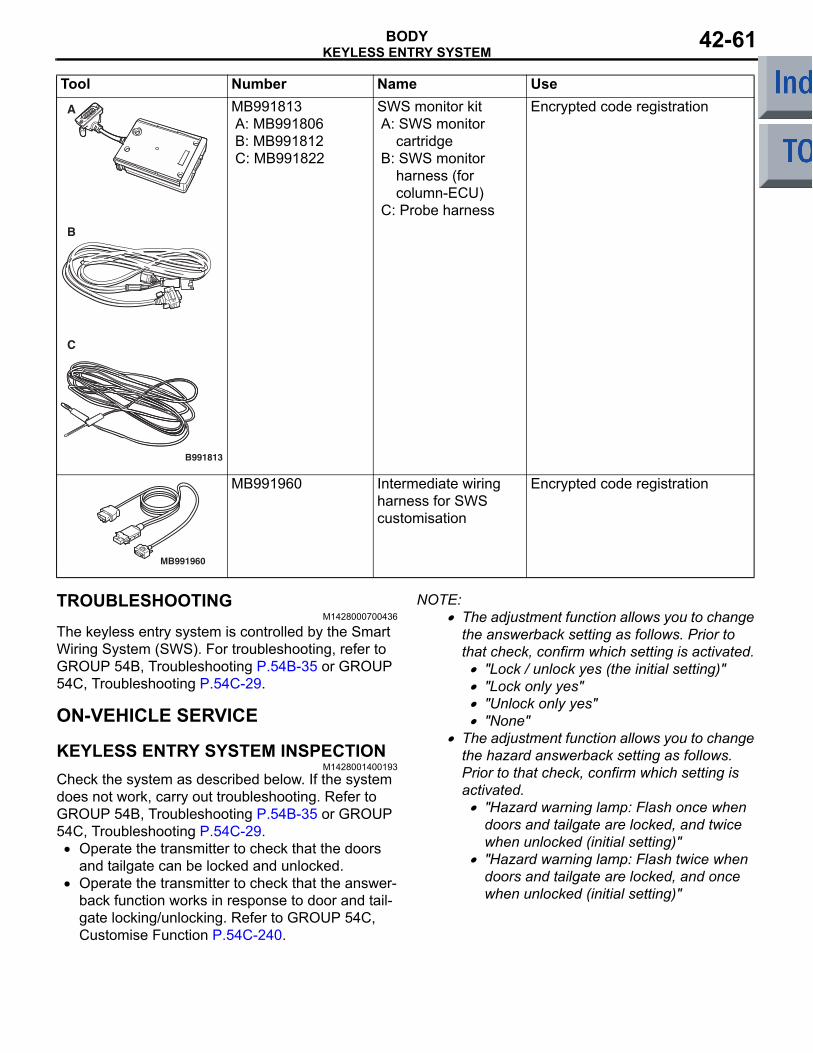
B991813
A
B
C
TROUBLESHOOTINGM1428000700436
The keyless entry system is controlled by the Smart Wiring System (SWS). For troubleshooting, refer to GROUP 54B, Troubleshooting P.54B-35 or GROUP 54C, Troubleshooting P.54C-29.
ON-VEHICLE SERVICE
KEYLESS ENTRY SYSTEM INSPECTIONM1428001400193
Check the system as described below. If the system does not work, carry out troubleshooting. Refer to GROUP 54B, Troubleshooting P.54B-35 or GROUP 54C, Troubleshooting P.54C-29.
• Operate the transmitter to check that the doors and tailgate can be locked and unlocked.
• Operate the transmitter to check that the answer-back function works in response to door and tail-gate locking/unlocking. Refer to GROUP 54C, Customise Function P.54C-240.
NOTE: .• The adjustment function allows you to change
the answerback setting as follows. Prior to that check, confirm which setting is activated.
• "Lock / unlock yes (the initial setting)"• "Lock only yes"• "Unlock only yes"• "None"
• The adjustment function allows you to change the hazard answerback setting as follows. Prior to that check, confirm which setting is activated.
• "Hazard warning lamp: Flash once when doors and tailgate are locked, and twice when unlocked (initial setting)"
• "Hazard warning lamp: Flash twice when doors and tailgate are locked, and once when unlocked (initial setting)"
MB991813A: MB991806B: MB991812C: MB991822
SWS monitor kitA: SWS monitor
cartridgeB: SWS monitor
harness (for column-ECU)
C: Probe harness
Encrypted code registration
MB991960
MB991960 Intermediate wiring harness for SWS customisation
Encrypted code registration
Tool Number Name Use

KEYLESS ENTRY SYSTEMBODY42-62
MULTI-MODE KEYLESS ENTRY FUNCTION INSPECTION
M1428004100083Operate the transmitter to check that the elec-tric-folding door mirrors work. If they do not work, carry out troubleshooting. Refer to GROUP 54B, Troubleshooting P.54B-35 or GROUP 54C, Trouble-shooting P.54C-29.
KEYLESS ENTRY SYSTEM TIMER LOCK FUNCTION INSPECTION
M1428004000246Attempt to unlock the doors and the tailgate by using the transmitter. If the doors and the tailgate are not locked within 30 seconds, carry out troubleshooting. Note that the doors and the tailgate will not be locked if the ignition key is inserted within the 30-second period, or one of the doors or the tailgate is opened. Refer to GROUP 54B, Troubleshooting P.54B-35 or GROUP 54C, Troubleshooting P.54C-29.NOTE: The customisation function allows you to change the keyless entry system timer lock period from 30 seconds (default setting) to 60, 120 or 180 seconds. Prior to the check, confirm which setting is activated. Refer to GROUP 54C, Customise Func-tion P.54C-240.
HOW TO REGISTER SECRET CODEM1428001000560
Each individual secret code is registered inside the transmitter, and so it is necessary to resister these codes with the EEPROM inside the receiver in the following cases.
• When the transmitter or ETACS-ECU is replaced• If more transmitters are to be used• If it appears that a problem is occurring because
of faulty registration of a code.A maximum of four different codes can be stored in the EEPROM memory (four different transmitters can be used). When the code for the first transmitter is registered, the previously registered codes for all transmitters are cleared. Therefore, if you are using four transmitters or are adding more transmitters, the codes for all transmitters must be registered at the same time.
WHEN THE SPECIAL TOOL V.C.I. (MB991824) IS USED1. Check that the doors lock normally when the key
is used.2. Insert the ignition key.
CAUTIONBefore connecting or disconnecting the V.C.I., turn the ignition switch to the "LOCK" (OFF) position.
AC312716AC206895
AB
MB991910
MB991824
16-Pin
3. Connect the V.C.I. to the diagnosis connector.
ACX00571
Within 10 seconds
Hazard warninglampswitch
ON
OFF
1 2 3 4 5 6
AQ
V.C.I. connected
4. Press the hazard warning lamp switch six times within 10 seconds.NOTE: Once the process is completed six times, then it will operate with all doors and tailgate lock and unlock operations once and then go to the save mode.NOTE: The hazard warning lamp switch is turned on and off alternately whenever it is pushed.

KEYLESS ENTRY SYSTEMBODY 42-63
5. Press the transmitter switch, and then press it two times within 10 seconds of the first press. This will register the code.
6. Once the program is saved, it will operate once with the all doors and tailgate lock and unlock operations.
7. If you are using two or more transmitters or have added a second transmitter, the next transmitter should be registered within one minute after registering the code for the previous transmitter. The registration procedure is common for all the transmitter.
8. Registration mode will be cancelled under the following conditions:
• When the secret code for four transmitters has been registered;
• When passing one minute after finishing the reg-istration of all transmitters;
• When the V.C.I. is disconnected from the diagno-sis connector;
• When the key is removed from the key cylinder;9. After the registration is completed, remove the
ignition key and close all the doors, and then check that the keyless entry system operates normally.
WHEN THE M.U.T.-III AND SWS MONITOR IS USED1. Check that the doors lock normally when the
ignition key is inserted into the door key cylinder and turned.
2. Insert the ignition key in the ignition switch.CAUTION
Before connecting or disconnecting the M.U.T.-III and SWS monitor, turn the ignition switch to the "LOCK" (OFF) position.
AC212114
MB991910
MB991806(SWS monitor)
MB991827
AB
MB991824
MB991960
16-Pin
3. Connect the SWS monitor to the M.U.T.-III. Refer to GROUP 54C, How to Connect The SWS Monitor P.54C-5.
4. Connect the M.U.T.-III to the diagnosis connector.5. Select "Interactive Diagnosis" from the main
menu.6. Select "System Select" from "Interactive
Diagnosis".7. Select "BODY" from the upper tab on "System
Select" window.8. Select "SWS" from "BODY".

KEYLESS ENTRY SYSTEMBODY42-64
9. Select "SWS Monitor" from "SWS".10.If "New communication between doors" is
selected from "SWS monitor", the display screen will be changed. Select "Keyless Entry" from that screen.
11.Select "Keyless ID Regist" from "Keyless Entry" items.
12.Press the YES key to clear encrypted codes for all the current registered transmitters.
13.Push the hazard warning lamp switch to clear all the encrypted codes completely.
14.Push the switch of the transmitter to be registered consecutively three times. If another transmitter is registered, push the switch of that transmitter again consecutively three times.
15.Return to the previous step.16.Select "Recept Inspect" from "Keyless Entry"
items.17.Push the transmitter switch. If the transmitter can
receive signal normally, the screen will show variation of the received signals and whether the transmitter switch has been registered or not.NOTE: For the keyless entry system, the signal reception can be examined regardless of whether the transmitter is registered or not.
18.Return to the main menu and complete.19.Remove the M.U.T.-III.20.Disconnect the SWS monitor.21.Check that the keyless entry system works
normally.

KEYLESS ENTRY SYSTEMBODY 42-65
TRANSMITTER
DISASSEMBLY AND REASSEMBLYM1428002800202
Post-installation operation• Transmitter operation check
AC310838
AC303199AC30411812
AF
5
3
4
6
Disassembly steps 1. Screw2. Upper cover3. Transponder
4. Transmitter assembly<<A>> >>A<< 5. Battery
6. Master key
Disassembly steps (Continued)

KEYLESS ENTRY SYSTEMBODY42-66
DISASSEMBLY SERVICE POINT<<A>> BATTERY REMOVAL
CAUTIONDo not allow water or dust to enter the inside of the transmitter assembly when it is open. Also, do not touch the precision electronic device.
REASSEMBLY SERVICE POINT>>A<< BATTERY INSTALLATION
CAUTIONDo not allow water or dust to enter the inside of the transmitter assembly when it is open. Also, do not touch the precision electronic device.
AC304118AD
+–
Master key side
Upper cover side
Battery
Transmitter assembly
Install a new battery to the transmitter assembly with its (+) side facing towards the upper cover side.
Battery required for replacement: Coin type battery CR1616
INSPECTIONM1428003800142
TRANSMITTER BATTERY CHECK
AC004486
Measure the voltage of the battery. If the voltage of the battery is not within the standard value, replace the battery.
Standard value: 2.5 − 3.2 V

SUNROOF ASSEMBLYBODY 42-67
SUNROOF ASSEMBLYSERVICE SPECIFICATIONS
M1421000300426
Item Standard valueSunroof lid glass operation current A (at 20 °C) 7 or less
TROUBLESHOOTING
DIAGNOSIS TROUBLESHOOTING FLOWM1426001700121
Refer to GROUP 00, How to use Troubleshoot-ing/inspection Service Points − Contents of Trouble-shooting P.00-5.
CHECK CHART FOR TROUBLE SYMPTOMS
M1426002000170
Symptom Inspection procedure number
Reference page
The sunroof does not work at all. 1 P.42-68Any of the sunroof switch positions is defective. 2 P.42-74

SUNROOF ASSEMBLYBODY42-68
SYMPTOM PROCEDURES
Inspection Procedure 1: The sunroof does not work at all.
CAUTIONWhenever the ECU is replaced, ensure that the input and output signal circuits are normal.
IGNITION SWITCH (IG2)
FUSIBLE LINK 6
HALL IC HALL IC
SUNROOF MOTOR ASSEMBLY
SUNROOF SWITCH
CONTROL CIRCUIT
Wire colour codeB : Black LG : Light green G : Green L : Blue W : White Y : Yellow SB : Sky blue BR : Brown O : Orange GR : Grey R : Red P : Pink V : Violet
AC510037
Sunroof-ECU Power Supply Circuit
AB

SUNROOF ASSEMBLYBODY 42-69
COMMENTS ON TROUBLE SYMPTOMIf the sunroof does not work at all, these power sup-ply circuit(s), these earth circuit(s), sunroof switch or the sunroof motor assembly (sunroof-ECU) may be defective.
PROBALE CAUSES• Malfunction of the sunroof switch• Malfunction of the sunroof motor assembly (sun-
roof-ECU)• Damaged harness wires and connectors
DIAGNOSIS PROCEDURE
STEP 1. Connector check: C-03 sunroof switch connector
AC401057
Harness side
Connector: C-03
AH
C-03 (B)
Q: Is the check result normal?YES : Go to Step 2.NO : Repair the connector.
STEP 2. Check the sunroof switch.Check that the sunroof switch works normally. Refer to P.42-79.
Q: Is the check result normal?YES : Go to Step 3.NO : Replace the sunroof switch.
STEP 3. Resistance measurement at the C-03 sunroof switch connector.
AC401057
Harness side
Connector: C-03
AH
C-03 (B)
(1) Disconnect the connector, and measure at the wiring harness side.
AC209731
6 45 3 2 1
Connector C-03 (Harness side)
AC208731AQ
(2) Continuity between C-03 sunroof switch connector terminal No.4 and body earth
OK: Continuity (Less than 2Ω)Q: Is the check result normal?
YES : Go to Step 5.NO : Go to Step 4.

SUNROOF ASSEMBLYBODY42-70
STEP 4. Check the wiring harness between C-03 sunroof switch connector terminal No.4 and body earth.
AC401057
Harness side
Connector: C-03
AH
C-03 (B)
NOTE:
AC401449
Harness side
AB
Connector: B-113Junction block (Front view)
AC401450
Harness side
AB
Connector: B-130Junction block (Rear view)
Prior to the wiring harness inspection, check junction block connector B-113 and B-130, and repair if nec-essary.
• Check the earth wires for open circuit.
Q: Is the check result normal?YES : The trouble can be an intermittent
malfunction (Refer to GROUP 00, How to use Troubleshooting/Inspection Service Points − How to Cope with Intermittent Malfunction P.00-13).
NO : Repair the wiring harness.
STEP 5. Connector check: C-05 sunroof motor assembly connector
AC401057
Harness side
AI
Connector: C-05 C-05 (GR)
Q: Is the check result normal?YES : Go to Step 6.NO : Repair the connector.
STEP 6. Voltage measurement at the C-05 sunroof motor assembly connector.
AC401057
Harness side
AI
Connector: C-05 C-05 (GR)
(1) Disconnect the sunroof motor assembly connector, and measure at the harness side.
(2) Ignition switch: ON
AC208730 AP
27
16
510
38
49
Connector C-05 (Harness side)
(3) Check the voltage between the C-05 sunroof motor assembly connector terminal No.3 and body earth.
OK: Battery positive voltageQ: Is the check result normal?
YES : Go to Step 8.NO : Go to Step 7.

SUNROOF ASSEMBLYBODY 42-71
STEP 7. Check the wiring harness between C-05 sunroof motor assembly connector terminal No.3 and the ignition switch (IG2).
AC401057
Harness side
AI
Connector: C-05 C-05 (GR)
NOTE:
AC401449
Harness side
AB
Connector: B-113Junction block (Front view)
AC401450
Harness side
AB
Connector: B-130Junction block (Rear view)
Prior to the wiring harness inspection, check junction block connector B-113 and B-130, and repair if nec-essary.
• Check the power supply line for open circuit.
Q: Is the check result normal?YES : The trouble can be an intermittent
malfunction (Refer to GROUP 00, How to use Troubleshooting/Inspection Service Points − How to Cope with Intermittent Malfunction P.00-13).
NO : Repair the wiring harness.
STEP 8. Voltage measurement at the C-05 sunroof motor assembly connector.
AC401057
Harness side
AI
Connector: C-05 C-05 (GR)
(1) Disconnect the sunroof motor assembly connector, and measure at the harness side.
AC208730 AQ
27
16
510
38
49
Connector C-05 (harness side)
(2) Check the voltage between the C-05 sunroof motor assembly connector terminal No.6 and body earth.
OK: Battery positive voltageQ: Is the check result normal?
YES : Go to Step 10.NO : Go to Step 9.

SUNROOF ASSEMBLYBODY42-72
STEP 9. Check the wiring harness between C-05 sunroof motor assembly connector terminal No.6 and the fusible link (6).
AC401057
Harness side
AI
Connector: C-05 C-05 (GR)
NOTE:
AC401451AB
Connectors: B-108, B-113Junction Block (Front view)
B-113
B-108 (B)
Harness side
B-108
Harness side
B-113
Prior to the wiring harness inspection, check junction block connector B-108 and B-113, and repair if nec-essary.
• Check the power supply line for open circuit.
Q: Is the check result normal?YES : The trouble can be an intermittent
malfunction (Refer to GROUP 00, How to use Troubleshooting/Inspection Service Points − How to Cope with Intermittent Malfunction P.00-13).
NO : Repair the wiring harness.
STEP 10. Resistance measurement at the C-05 sunroof motor assembly connector.
AC401057
Harness side
AI
Connector: C-05 C-05 (GR)
(1) Disconnect the sunroof motor assembly connector, and measure at the harness side.
AC209731
Connector C-05(Harness side)
AC208731AR
27
16
510
38
49
(2) Check the resistance between C-05 sunroof motor assembly connector terminal No.1 and body earth.
OK: Continuity (Less than 2Ω)Q: Is the check result normal?
YES : Go to Step 12.NO : Go to Step 11.

SUNROOF ASSEMBLYBODY 42-73
STEP 11. Check the wiring harness between C-05 sunroof motor assembly connector terminal No.1 and body earth.
AC401057
Harness side
AI
Connector: C-05 C-05 (GR)
NOTE:
AC401449
Harness side
AB
Connector: B-113Junction block (Front view)
AC401450
Harness side
AB
Connector: B-130Junction block (Rear view)
Prior to the wiring harness inspection, check junction block connector B-113 and B-130, and repair if nec-essary.
• Check earth line for open circuit.
Q: Is the check result normal?YES : The trouble can be an intermittent
malfunction (Refer to GROUP 00, How to use Troubleshooting/Inspection Service Points − How to Cope with Intermittent Malfunction P.00-13).
NO : Repair the wiring harness.
STEP 12. Retest the system.The sunroof assembly should now work normally.
Q: Is the check result normal?YES : The trouble can be an intermittent
malfunction (Refer to GROUP 00, How to use Troubleshooting/Inspection Service Points − How to Cope with Intermittent Malfunction P.00-13).
NO : Replace the sunroof motor assembly.

SUNROOF ASSEMBLYBODY42-74
Inspection Procedure 2: Any of the sunroof switch positions is defective.
CAUTIONWhenever the ECU is replaced, ensure that the input and output signal circuits are normal.
AC510038
SUNROOF MOTOR ASSEMBLY
SUNROOF SWITCH
CONTROL CIRCUIT
Wire colour codeB : Black LG : Light green G : Green L : Blue W : White Y : Yellow SB : Sky blue BR : Brown O : Orange GR : Grey R : Red P : Pink V : Violet
Sunroof Switch Circuit
AB
COMMENTS ON TROUBLE SYMPTOMIf any of the sunroof switch positions is defective, the communication line between the sunroof switch and the sunroof motor assembly (sunroof-ECU) may be defective.
PROBALE CAUSES• Malfunction of the sunroof switch• Malfunction of the sunroof motor assembly (sun-
roof-ECU)• Damaged harness wires and connectors

SUNROOF ASSEMBLYBODY 42-75
DIAGNOSIS PROCEDURE
STEP 1. Connector check: C-03 sunroof switch connector
AC401057
Harness side
Connector: C-03
AH
C-03 (B)
Q: Is the check result normal?YES : Go to Step 2.NO : Repair the connector.
STEP 2. Check the sunroof switch.Check that the sunroof switch works normally. Refer to P.42-79.
Q: Is the check result normal?YES : Go to Step 3.NO : Replace the sunroof switch.
STEP 3. Connector check: C-05 sunroof motor assembly connector
AC401057
Harness side
AI
Connector: C-05 C-05 (GR)
Q: Is the check result normal?YES : Go to Step 4.NO : Repair the connector.
STEP 4. Retest the system.Q: Which switch position is defective?
"TILT UP" : Go to Step 5."OPEN" : Go to Step 6."CLOSE/DOWN" : Go to Step 7.
STEP 5. Check the wiring harness between C-05 sunroof motor assembly connector terminal No.4 and C-03 sunroof switch connector terminal No.3.
AC401057
Harness side
AJ
Connectors: C-03, C-05 C-05 (GR)
C-05
C-03Harness side C-03 (B)
• Check the communication line for open circuit.
Q: Is the check result normal?YES : Replace the sunroof motor assembly.NO : Repair the wiring harness.
STEP 6. Check the wiring harness between C-05 sunroof motor assembly connector terminal No.5 and C-03 sunroof switch connector terminal No.5.
AC401057
Harness side
AJ
Connectors: C-03, C-05 C-05 (GR)
C-05
C-03Harness side C-03 (B)
• Check the communication line for open circuit.
Q: Is the check result normal?YES : Replace the sunroof motor assembly.NO : Repair the wiring harness.

SUNROOF ASSEMBLYBODY42-76
STEP 7. Check the wiring harness between C-05 sunroof motor assembly connector terminal No.10 and C-03 sunroof switch connector terminal No.6.
AC401057
Harness side
AJ
Connectors: C-03, C-05 C-05 (GR)
C-05
C-03Harness side C-03 (B)
• Check the communication line for open circuit.
Q: Is the check result normal?YES : Replace the sunroof motor assembly.NO : Repair the wiring harness.

SUNROOF ASSEMBLYBODY 42-77
ON-VEHICLE SERVICE
WATER TESTM1426000900337
Check if there are any leaks in the sunroof by the fol-lowing procedure.1. Fully close the roof lid glass.2. Adjust the water pressure so that water comes out
of the hose to a height of approximately 50 cm when the hose is held vertically facing upwards.
ACX00572 AE
Hose
Approx30 cm
3. Hold the end of the hose approximately 30 cm above the roof and let the water run onto the weatherstrip for 5 minutes or more.
4. Check if any water leaks can be found in the room while watering. Even though there are any water leaks around the roof lid glass, it can be acceptable as long as water is caught in the drip area.
SUNROOF FIT ADJUSTMENTM1426001000359
1. Close the roof lid glass fully.2. Open the sun shade fully.
AC208235AB
3. Loosen the roof lid glass assembly mounting screws. Adjust the roof lid glass height by moving the glass assembly along the guide oblong hole so that the clearance between the glass and the vehicle body is even.
4. After adjustment, check that the sunroof operates smoothly.
SUN ROOF OPERATION CHECKM1426002600387
Check to see that the sunroof operates by pressing the sunroof switch. If it does not operate, perform troubleshooting. Refer to P.42-67.
ROOF LID GLASS OPERATION CURRENT CHECK
M1426003200229
AC208585AE
Sunroof fuse
J/B
1. Remove the fuse of the sunroof then connect the circuit tester as shown in the Figure.
2. Turn ON the sunroof switch then measure the operating current of the intermediary segment when operations is starting, the sunroof is fully closed, the sunroof is fully opened and the sunroof is tilted fully up.
Standard value: 7 A or less (at 20 °C)3. Check the following areas if the operating current
of the roof lid glass exceeds the standard value.• Sunroof assembly assembling state, deformation
and biting of any foreign substances.• Drive cable fastening• Tilting of roof lid glass
INITIALISATION OF SUNROOFM1426004600190
1. When the tilt-up switch remains pressed for approximately 10 seconds, the sunroof tilts up fully from the closed position.
2. After the sunroof has stopped at the fully tilted-up position, release the switch.
3. When the tilt-up switch remains pressed for approximately 5 seconds again within approximately 5 seconds after it has been released, the sunroof will begin to operate again.
4. Continue pressing the tilt-up switch further until the sunroof is opened fully and then closed fully.NOTE: If the tilt-up switch is released while the sunroof is moving, the initialisation will be can-celled. Repeat the procedures.

SUNROOF ASSEMBLYBODY42-78
SUNROOF ASSEMBLY
REMOVAL AND INSTALLATIONM1426001200472
Post-installation Operation <Roof lid glass assembly, Sunroof assembly>• Sunroof Water Test (Refer to P.42-77).• Sunroof Fit Adjustment (Refer to P.42-77).• Sunroof Initialising Adjustment (Refer to P.42-77).
AC208804
Section A – A
AC
1
2
3
3
2
4
5
6
7
8
9
10
Claw
Note : Claw positions
AA
3.0 ± 0.5 N·m
Sunroof lid glass assembly removal
1. Sunroof lid glass assemblySunroof switch removal steps
2. Sunroof switch cover• Headlining (Refer to GROUP 52A,
Headlining P.52A-16).
Sunroof switch removal steps (Continued)
3. Sunroof switch4. Map lamp bracket
Sunroof motor assembly removal steps
2. Sunroof switch cover

SUNROOF ASSEMBLYBODY 42-79
INSTALLATION SERVICE POINT>>A<< REAR DRAIN PIPE/FRONT DRAIN PIPE INSTALLATION
AC208586 AC
<Front drain pipe>
<Rear drain pipe>
25 ± 5
5 ± 5
Unit: mm
Marking part
Grommet
Grommet Marking part
Install the grommet. Adjust the drain pipe projection as shown.
INSPECTIONM1426004700335
SUNROOF SWITCH CONTINUITY CHECK
AC005659
41 3 5 62
Switch position Tester connection
Specified condition
Open 4 − 5 Continuity (Less than 2Ω)
OFF 3 − 4, 3 − 5, 3 − 6, 4 − 5, 4 − 6, 5 − 6
Open circuit
UP 3 − 4 Continuity (Less than 2Ω)
Close/Down 4 − 6 Continuity (Less than 2Ω)
• Headlining (Refer to GROUP 52A, Headlining P.52A-16).
5. Sunroof motor assemblySunroof assembly removal steps
2. Sunroof switch cover• Headlining (Refer to GROUP 52A,
Headlining P.52A-16).6. Assist grip bracket7. Drain pipe connection
8. Sunroof assemblyDrain pipe removal steps
2. Sunroof switch cover• Headlining (Refer to GROUP 52A,
Headlining P.52A-16).• Splash shield (Refer to P.42-7).
>>A<< 9. Front drain pipe• Rear combination lamp assembly
(Refer to GROUP 54A, Rear Combination Lamp Assembly, P.54A-81).
>>A<< 10. Rear drain pipe
Sunroof motor assembly removal steps (Continued)
Sunroof assembly removal steps (Continued)

SUNROOF ASSEMBLYBODY42-80
SUNROOF MOTOR ASSEMBLY TERMINAL CHECK
54321
109876
AC510039
C-05
AB
Terminal No.
Check item Check condition Normal condition
1 Earth Always 0 V2 − − −
3 Power supply from ignition switch (IG2)
Ignition switch: ON System voltage
4 Input from sunroof switch (Tilt-up) Sunroof switch: Tilt-up 0 V5 Input from sunroof switch (Open) Sunroof switch: Open 0 V6 System voltage (Motor) Always System voltage7 − − −
8 − − −
9 − − −
10 Input from sunroof switch (Close/Tilt-down)
Sunroof switch: Close/Tilt-down 0 V

LOOSE PANELBODY 42-81
LOOSE PANELREMOVAL AND INSTALLATION
M1421003100379
AC601183AB
24 ± 4 N·m
9.0 ± 2.0 N·m
3
5
6
20 ± 4 N·m9.0 ± 2.0 N·m
4
105 ± 15 N·m
5.0 ± 1.0 N·m
20 ± 4 N·m
9
11
13 ± 2 N·m
2
1
5.0 ± 1.0 N·m
5.0 ± 1.0 N·m22 ± 4 N·m
10
7
24 ± 4 N·m
7
8
Cowl top panel removal steps • Windshield wiper motor and Link
assembly (Refer to GROUP 51, Windshield Wiper P.51-29.)
1. Cowl top panelBackbone brace removal
2. Backbone braceFront bumper reinforcement damper removal steps
• Hood latch (Refer to P.42-5.)3. Front bumper reinforcement damper
<Vehicles without RALLIART Version-R>
4. Dynamic damper bracket <Vehicles without RALLIART Version-R>
Front suspension axle side plete removal steps
5. Front suspension axle side plete <Vehicles with RALLIART Version-R>Upper frame to front pillar brace removal step
• Splash shield (Refer to P.42-7.)6. Upper frame to front pillar brace
<Vehicles with RALLIART Version-R><<A>> >>A<< 7. Rivet <Vehicles with RALLIART
Version-R>8. Front fender side bracket <Vehicles
with RALLIART Version-R>Floor guard bar removal steps
9. Floor guard bar <Vehicles with RALLIART Version-R>

LOOSE PANELBODY42-82
Child restraint bracket removal • Rear bumper assembly (Refer to
GROUP 51, Rear Bumper Assembly P.51-7.)
10. Child restraint bracketRear pillar inner panel removal steps
• Quarter trim upper (Refer to GROUP 52A, Interior trim P.52A-11.)
11. Rear pillar inner panel <Vehicles with RALLIART Version-R>
REMOVAL SERVICE POINT<<A>> RIVET REMOVAL
AC303663AH
Rivet
Drill
Upper frame to front pillar brace
Use a drill (4.0 mm) to make a hole in the rivet to break it, and then remove the rivet.
INSTALLATION SERVICE POINT>>A<< RIVET INSTALLATION
AC205819AB
Recommended tool
Use recommended tool shown in the illustration to connect the rivet by the following procedure.
AC601325AC
1
2
3
4
Section A
Flange
Rivet
Rivet
Recommended tool
1. Insert the rivet into the base material (upper frame to front pillar brace and front fender side bracket).
2. Place the recommended tool over section A of the rivet.
3. While pushing the flange surface of the rivet with the recommended tool, press the handle of the tool.
4. The thin part of section A of the rivet will break and the rivet will then be attached.