group 10 – helping hand kurt graf matt carlson eric donley taylor jones
TRANSCRIPT

Group 10 – Helping Hand
Kurt Graf
Matt Carlson
Eric Donley
Taylor Jones

Our Project Is
A haptic robotic arm controlled by a sleeve mounted with motion and force sensors on a human operator's arm – which controls the motion-tracking robotic arm's proportional motion.
These robots have a wide range of industrial and medical applications such as pick and place robots, surgical robots etc. They can be employed in places where precision and accuracy are required. Robots can also be employed where human hand cannot penetrate.

The Future of Technology
The interpretation is computers tell the machinery what to do and the power electronics implements the actual actions.
Power electronics refers to control and conversion of electrical power by power semiconductor devices wherein these devices operate as switches.
“The future of technology is computers and power electronics” - recent IEEE literature

Motivation for Project
• We are Electrical Engineers and Computer Engineer candidates for a bachelor of science diploma
• Concern for real working world (industrial) knowledge and skills led the team to choose for senior design project a modern application of an industrial standard robotic application - the robotic arm.
• Our application is more sophisticated technologically than original manufacturing and packaging and assembly robotic arms like the Unimate (See picture next slide) the original robot arm was basically an open-loop control scenario:
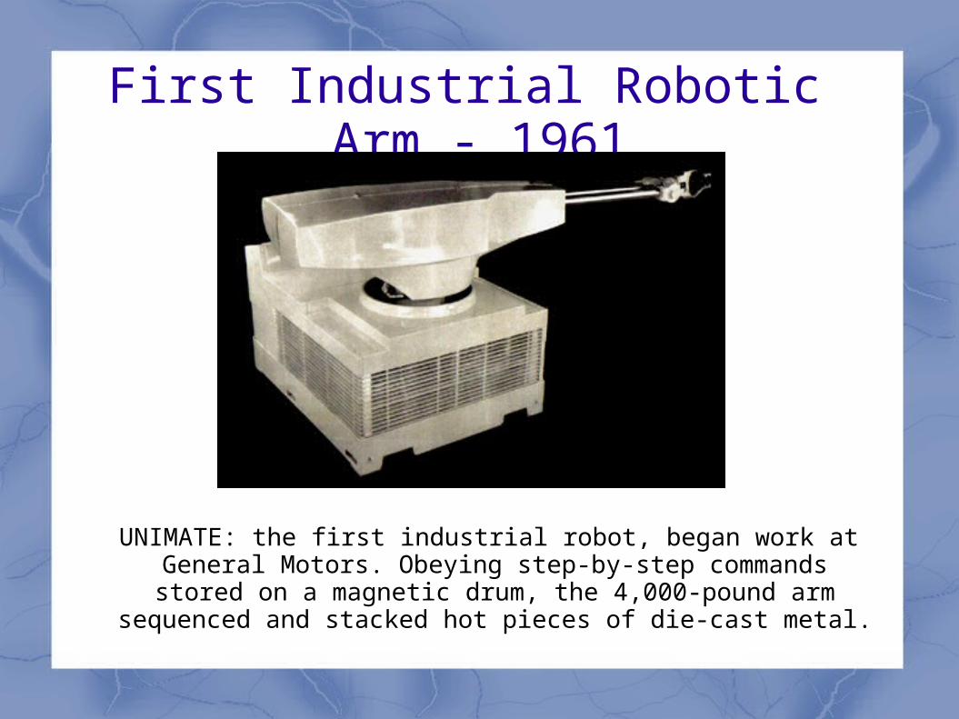
First Industrial Robotic Arm - 1961
UNIMATE: the first industrial robot, began work at General Motors. Obeying step-by-step commands stored on a magnetic drum, the 4,000-pound arm sequenced and
stacked hot pieces of die-cast metal.
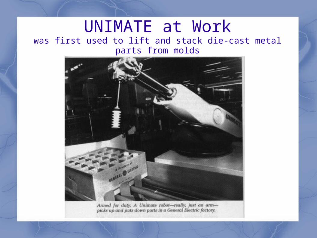
UNIMATE at Workwas first used to lift and stack die-cast metal parts from molds

Over 1,000,000 current working industrial robots
Over 100,000 new industrial robots each year
Most common type of robotic device is the robot arm
The most common type of existing robotic device is the robot arm often used in industry and manufacturing. The mechanical arm recreates many of the movements of the human arm, having not only side-to-side and up-and-down motion, but also a full 360-degree circular motion at the wrist, which humans do not have. Robot arms are of two types. One is computer-operated and programmed for a specific function. The other requires a human to actually control the strength and movement of the arm to perform the task.

Current Light Industry Robot Arms

modern assembly line robot arm(s)

A large robot arm that controls you!

A Very Large Robot Arm- Caterpillar Large Hydraulic Excavators

A new wave in robot arms (two of 'em) -BAXTER
Rodney Brooks's new start-up wants to spark a factory revolution with a low-cost, user-friendly robot - IEEE

BAXTERIncludes two 7 DOF arms with torso and head,
integrated vision system, integrated robot control system, integrated safety system.
http://www.rethinkrobotics.com/

Learn about Robotics
Robotic systems Wireless systems IC/MEMS manufacture Radar, Antennas Power Electronics
Are all virtually or literally EE grad school only subjects.

Robot Arm Update
Our application of a human arm motion-tracking robot arm is intended more like the robot arms used in robot surgery.
Theoretically, adding digits (fingers) to the arm with extremely fine control could make a skilled work duplication station possible.
That means you make a part at your workstation and the Helping Hand duplicates your work on a robotic station.

An alien abduction simulator?
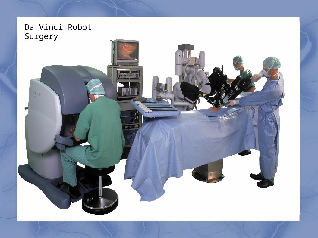
Da Vinci Robot Surgery


Manual control looks like a two handed joystick

Da Vinci System
Using the most advanced technology available today, the da Vinci Surgical System enables surgeons to perform delicate and complex operations through a few tiny incisions with increased vision, precision, dexterity and control. The da Vinci Surgical System consists of several key components, including: an ergonomically designed console where the surgeon sits while operating, a patient-side cart where the patient lays during surgery, four interactive robotic arms, a high-definition 3D vision system, and proprietary EndoWrist® instruments.
da Vinci is powered by state-of-the-art robotic technology that allows the surgeon’s hand movements to be scaled, filtered and translated into precise movements of the EndoWrist instruments working inside the patient’s body.

Goals and Objectives of Our Project
1. Proportional motion-tracking of a human operator's arm motion
2. Fast tracking response (shadow boxing in Real Steal)
3. Effective grasp-and-place object with end- effector
4. Smooth and safe and stable motion
5. Bold attempt at 7th DOF with elbow roll

Human Arm Motion plus Sensors

Specifications of Performance
1. Less than 0.1 second (human reaction time) delay from human arm motion to robot arm motion-tracking
response
2. Automatic reset to “home base” position
3. Work volume range-of-motion computer tracked.
4. Internal range-of-motion limitation fail-safes
5. Grasp, lift, and place 13 oz payload
6. End-effector does not damage payload

Basic Idea of Motion Tracking (dc motor prototype)
Human ArmMotion
Robot Arm Motion
Sensors Processing Actuation

Not an Open Loop SystemExteroceptive (operator) Feedback

System Schematic (dc motors)

System Schematic (servo motors)

System Schematic (wireless)

Power Supply
• 3 voltage power supply for
• 3.3V sensors/ mcu
• 5.0V sensors
• 6.0V servos
• 2 Buck regulators
• One with multiple loads

8 AA Battery Holder

Power supply schematic

Invensense MPU-60506-axis gyroscope and accelerometer
4 x 4 x 1 mm

MPU-6050
Supply voltage of
2.375V – 3.46V
Current of 3.9mA
Uses an I2C bus
Selectable gyroscope and accelerometer ranges
1MHz internal clock

How MEMS Gyroscope Works

GYRO equation
The gyro gives data in degrees/second
To determine actual angle of rotation requires integration with
respect to time
∫dΘ dt = Θ

Actual MEMS Gyro Construction


starting loop X: -4 Y: 109 Z: -9 // these are values when the gyro isn't moving X: -5 Y: 72 Z: -17 X: 22 Y: 81 Z: 5 X: 13 Y: 75 Z: 30 X: 11 Y: 75 Z: 67 X: 9 Y: 89 Z: 4 X: 0 Y: 95 Z: 38 X: -12 Y: 88 Z: 32 X: 18 Y: 66 Z: 49 X: 19 Y: 93 Z: 70
X: 27406 Y: -2091 Z: -29629 // these are values after a quick move of the gyro // inside loop
X: 35 Y: 67 Z: 12 // next values after motion stopped X: 26 Y: 74 Z: 50
Sample Gyro (3-axis) data [degrees/second]

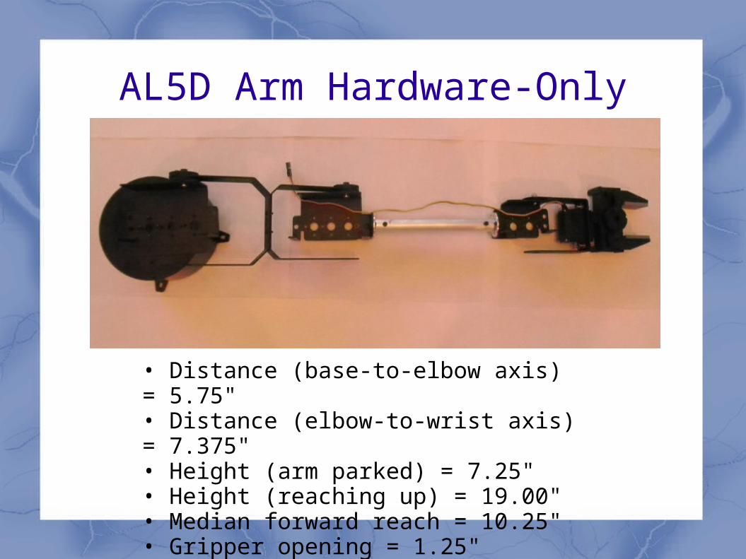
AL5D Arm Hardware-Only
• Distance (base-to-elbow axis) = 5.75" • Distance (elbow-to-wrist axis) = 7.375" • Height (arm parked) = 7.25" • Height (reaching up) = 19.00" • Median forward reach = 10.25" • Gripper opening = 1.25"

MicrocontrollersName I/O pins Memory A/D converter Language Price
Basic ATOM 24 24 14k code368 RAM
256 EEPROM
11 channels BASIC $8.95
PICAXE-20X2 18 4k code256 RAM
11 channels BASIC $3.88
ATxmega128A4U 34 128k code8k SRAM
2k EEPROM
12 channels C/C++ orassembly
$3.00
Propeller 40 pin DIP 32
64k RAM/ROM
0 channels Spin $7.99

Initial Design of MCU Board

Sensor Data Conversion
Determining axis of rotation:
x coordinate = M21 - M12 / √(M21 – M12)2+(M02 – M20)2+(M10 – M01)2)y coordinate = M02 – M20 / √(M21 – M12)2+(M02 – M20)2+(M10 – M01)2)z coordinate = M01 – M10 / √(M21 – M12)2+(M02 – M20)2+(M10 – M01)2)
Determining Angle to axis’:
Angle to x axis = cos-1(x / √(x2 + y2 + z2))Angle to y axis = cos-1(y / √(x2 + y2 + z2))
Angle to z axis = cos-1(z / √(x2 + y2 + z2))

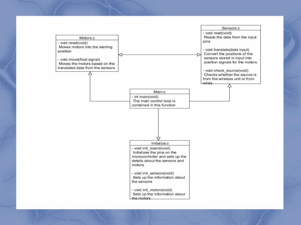
Motor Coordination

Operating Flowchart
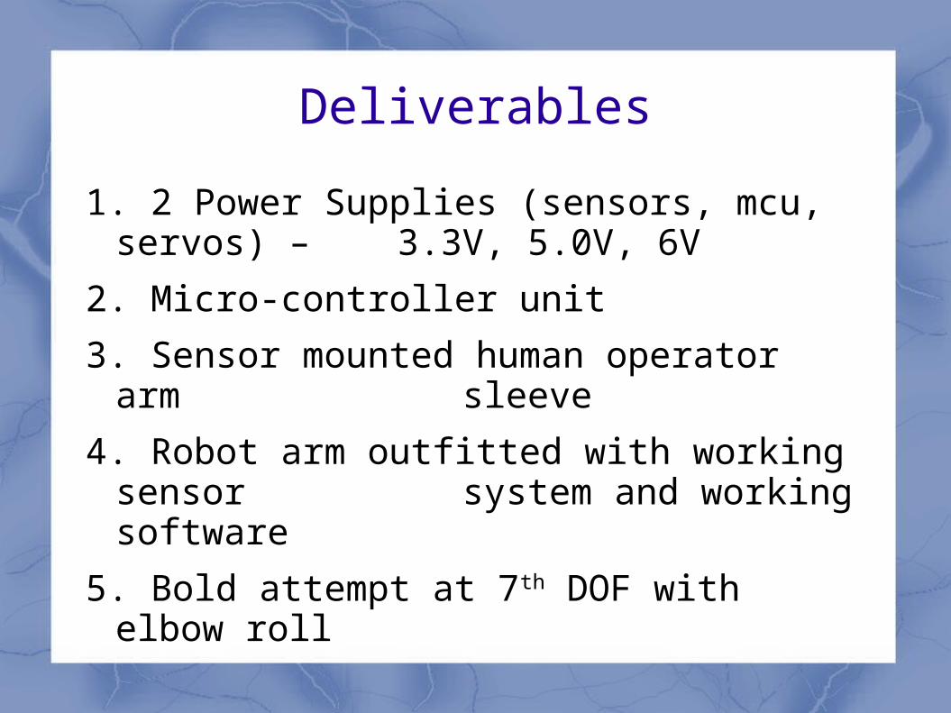
Deliverables
1. 2 Power Supplies (sensors, mcu, servos) – 3.3V, 5.0V, 6V
2. Micro-controller unit
3. Sensor mounted human operator arm sleeve
4. Robot arm outfitted with working sensor system and working software
5. Bold attempt at 7th DOF with elbow roll

Administrative
project is self-funded
- arm h/w is $165
- servos are ? < $200
- sensors about $100
- misc parts for power supply, construction $100
Target budget is < $800 = 4 x 4914 textbook

Progress Status
Basic Prototype (1 sensor) - 95%
Research – 80%
Component Identification – 85%
Coding - 20%
PC Board (MCU) – 30%
PC Boards (components) – 30%
Power Supply Board – 25%
Servo purchase - 0%

CHALLENGES
getting response time under 0.1 seconds system stable system easy to use safe payload handling Getting DMP pre-process data from sensors Bold attempt at 7th DOF with elbow roll
(rotatable wrist and elbow

QUESTIONS
???