ground water - world health organization · reproduced from tolman, c. f. (1937) ground water, p....
TRANSCRIPT

Chapter 3
GROUND WATER I
Engineering and Geological Considerations
Ground water serves the great majority of people who live in rural areas and have a water-supply system of one type or another. The reason is
1 that, among the various sources of supply, ground water is by far the most I practical and safe in nature. Even in a highly industrialized country such
as the USA, municipal ground-water installations far outnumber surface- water supplies. It is very probable that, for a long time to come, ground water will be the most important source of supply for most rural communi- ties of the world.
The advantages of ground water are : (I) it is likely to be free of pathogenic bacteria; (2) generally, it may be used without further treatment; (3) in many instances it can be found in the close vicinity of rural
I I / comnlunities ;
(4) it is often most practical and economical to obtain and distribute; (5) the water-bearing stratum from which it is drawn usually provides
a natural storage at the point of intake. The disadvantages are : (1) ground water is often high in mineral content; (2) it usually requires pumping. In ground-water-supply investigations and design, the engineer is con-
cerned with the following steps : (1) to find it in the required quantity and quality as near as possible
I
I to the centre of consumption, in order to reduce transport costs ;
1 (2) to extract it by means of a system which produces the quantity I required, safeguards the quality, and, at the same time, involves the least
I capital outlay ;
(3) to transport the water to the consumer in a way which requires the least amount of operational and maintenance skill and cost.
This section is concerned chiefly with the first step mentioned above. Obviously, a rural town or village cannot afford the cost involved in bringing water long distances by gravity or, much less, by pumpmg. The

58 WATER SUPPLY FOR RURAL AREAS
water which will serve a rural community must therefore be found within a rather limited area.
A brief discussion regarding the occurrence of ground water and the characteristics of underground formations from which it can be extracted may be valuable to the designing engineer.
Fig. 4. GEOLOGICAL FORMATIONS
1 = Areas where there are good possibilities of obtaining water from infiltration galleries, well-poinl systems
2 = Ground water is outcropping at this point, so that a flowing spring is formed. A t the foot of rivet banks and hills other springs may possibly be found.
3 = Top of ground-water table 4 = Area of infiltration t o supply formation B A = Non-confined (non-artesian), water-bearing formation covered with top soil B = Confined (artesian), water-bearing formation C = Impervious rock, o r hard-pan formation
To supply a village situated along the banks of the main river in this rolling country w i th a good grounc water table, the first thing t o look for is a spring above the town that could be developed and would f low b) gravity. If no springs were found within a reasonable distance above the point of consumption, some migh~ be found outcropping near the stream bed. If no springs were found within a reasonable distance, any we1 penetrating formation A would produce water. If large quantities were required, a well-point system o r ; gallery at points indicated would probably work. A deep well, properly constructed and developed, pene. trating formation B would probably produce considerable water.
The engineer making a survey of this area, knowing what is shown in this figure, ought t o follow a pro. cedure such as described above.

I ZONE OF .INTERCONNECTED OPENINGS I
VARIETIES OCCURRING THROUGHOUT ZONE OF SUSPENDED WATER z
: z
SATURATED ZONE
GROUND WATER (PHREATIC WATER)
UNDERSATURATED ZONE (ZONE OF AERATION)
SUSPENDED WATER

60 WATER SUPPLY FOR RURAL AREAS
Fig. 6. COMPARISON O F FREE A N D C O N F I N E D G R O U N D W A T E R
BC = theoretical static level of contined water body BC' = pressure gradient; indicates actual static level in wells piercing the conduit
Reproduced from Tolman, C. F. (1937) Ground water, p. 55, by kind permission of McGraw-Hill Book Co., Inc., New York
Occurrence
Ground water is that portion of the atmospheric precipitation, mostly rainfall, which has percolated into the earth to form underground deposits called aquifers (water-bearing formations) ( see Fig. 4 ). These can be tapped by various means, to be discussed later; and, in the great majority of cases, they can be used without further treatment for individual and com- munity water-supplies in rural areas. Fig. 5 shows the occurrence and distribution of subsurface water.
The great majority of wells for rural water-supplies take water from the zone which Tolman 35 defines as the " free-water zone " (Fig. 5, 6). These will usually be jetted, dug, driven, or bored wells. Infiltration gal- leries also take water from this zone. Drilled wells often penetrate the confined water aquifer. It is from this stratum that flowing wells are developed.
The aquifer must be supplied with an ample quantity of water if it is to serve as a source. It is simply a reservoir and can be depleted in the same manner as a surface reservoir if its supply is inferior to the demand placed on it. In rural areas this is very seldom a concern as the aquifer will usually be replenished sufficiently to supply the relatively small demands of rural communities. An element of greater significance for the engineer

INSTALLATION OF WATER-SUPPLY SYSTEMS 6 1
searching for ground water pertains to the characteristics of the soil form- ation of the aquifer, i.e., to the ability of the aquifer to give up water and, therefore, to serve as a reliable source of supply.
The quantity of water that can be extracted from an aquifer will depend on (1) its porosity and permeability, and (2) the draw-down in the well. The porosity and the permeability of a formation are limited by nature; and, while gravel packing a may alter conditions somewhat in the imme- diate vicinity of a well intake, the general nature of the aquifer is fixed and
Fig. 7. SHALLOW WELL I N FREE-WATER Z O N E
P
A = Ground surface B = Top layers of soil C = Water-bearing stratum D = Impervious stratum E = Thickness of water-bearing
stratum F = Water table
WHO 8296 b
G = Draw-down H = Depth of penetration of well
into aquifer I = Draw-down cone J = Curve of maximum draw-down P = Pump R = Radius of circle of influence
a Gravel packing is the development of a pocket of coarse, graded sand and gravel around a well intake- pipe to exclude fine sand and improve entrance velocity of water into the pipe.

62 WATER SUPPLY FOR RURAL AREAS
cannot be modified. The draw-down in a well, however, can be varied within the limits of the thickness of the aquifer, the penetration of the well into the aquifer, and the capacity of the pump used (see Fig. 7, 8).
Fig. 8. WELL TAPPING CONFINED WATER
P
wno 82*6 a
A = Ground surface F = Water table C = Water-bearing stratum G = Draw-down D = Impervious stratum I = Draw-down cone E = Thickness of water-bearing Q = Depth of water in well
stratum R = Radius of circle of influence
The porosity of a formation is the pore space between the particles which make up the formation. It is the volume of the voids. Obviously, a solid piece of dense rock will have low porosity-a low volume of pore space or voids. If many pieces of stone of varying shapes and sizes replace the single piece of the same total volume, the porosity will increase since the voids are increased. Steel 32 gives the following figures regarding the porosity of common soils and rocks : sands and gravels of fairly uniform size and moderately compacted, 35 %-40%; well-graded and compacted sands and gravels, 25 %-30 %; sandstone, 4 %-30 %; chalk, 14 %-45 %; granite, schist,

INSTALLATION OF WATER-SUPPLY SYSTEMS 63
and gneiss, 0.02 %-2 %; slate and shale, 0.5 %-8 %; limestone, 0.5 %-17 %; clay, 44 %-47 %; topsoils, 37 %-65 %. Fair & Geyer l6 report that silts may be as high as 80 % in porosity. It can be seen that soils with fine, separate particles, such as clay, topsoil, and silt, have a very high porosity. In other words, they have a big volume in which water can be stored.
Ground formations, however, have a certain tendency to hold the water and to give up only a part of it. This characteristic of a soil formation is called permeability; it is the quality of a formation which controls the passage of water through it. From a knowledge of hydraulics, it is obvious that water will pass through large openings more easily than it does through small ones.
Clays and topsoils have high porosity (large volume of voids) but low permeability (very small opening between particles), so that water passes through them with great difficulty. Gravels and sands, on the other hand, are permeable and therefore allow ground water to pass with relative ease. This type of formation is also porous, as can be seen above, so that it can store large quantities of water. These, then, are the water-bearing for- mations most amenable to the development of wells and most important to the engineer in searching for a rural community water-supply. Sandstone is both porous and pervious and therefore an excellent aquifer which can be tapped to produce large quantities of water, especially if it is confined as shown in Fig. 4 (formation B) and Fig. 5 (see pages 58 and 59). Where it is known, for example, that sandstone underlies an area, and where no other readily available source is found, a test hole into this stratum would be a good risk. Chalk formations in the British Isles and in Haiti are known to produce reasonable quantities of water.
Except for unusual geological features or underground dams, it can be said that, in any drainage basin, ground water always flows towards the principal streams (Fig. 4). While there are exceptions to this rule, the best place to look for shallow ground-water is at the bottom of draws and valleys. It is in this area that pockets of sand and gravel may have been deposited. If these are close to the present stream or in an old course, they will pro- bably be well supplied. Underground sampling by boring or jetting in these areas will usually be profitable. In this way, samples of the under- ground formation can be taken and examined to determine the charac- teristics of the aquifer and its ability to supply the quantity of water needed. Fortunately, a great many small towns in rural, underdeveloped areas have been built along natural watercourses, so that the possibility of finding available ground water as a source of supply may be somewhat improved in such areas.
Finding ground water
Rarely will the investigating engineer have at his disposal the results of previous geological studies of the particular area involved and, even more

64 WATER SUPPLY FOR RURAL AREAS
rarely, the services of a specialist in the field of ground-water geology. If such studies or services are available, they should be used by all means. If not, the engineer will usually have to exercise his own knowledge and judgement and to utilize his own resources. If he decides that it will be necessary to search for ground water, he may wish to consult helpful sources of information on this subject.
In prospecting for ground water, the first step is to review reports (if any) of relevant geological studies which indicate the nature and perhaps the characteristics of the underlying formations. Depending on the pur- pose for which these studies were made, they can be very useful in orientk ing the initial stage of investigation. Secondly, the examination of exist- ing wells-their profiles, production, water quality, and location-will also give valuable information. Thirdly, the sinking of test holes will be most profitable. While the last will entail more work and expense than the previous steps, experience has shown that test holes are, in almost every case, indispensable and, in the long run, economical as well. Samples and profiles of the ground formations can be obtained from test holes, thus giving information as to the nature of the aquifer, depth of the water table, and quality of the ground water. Furthermore, many test holes can also be pumped in order to obtain an indication of the possible yield of the aquifer. Most experienced technicians in the field of ground water will vigorously argue the need for exploratory borings and will insist that they are indispensable in previously unexplored areas. A fourth means of obtaining information about ground water is through the use of an electric- resistance system. Bymeasurement of the resistance of the earth at the desirable well locations and application of formulae developed by the manu- facturers of the equipment, reasonably accurate ground data can be obtained. The interpretation of the results of such tests, however, requires consider- able experience; and this method is most useful to supplement and extend the information obtained from actual well profiles. When properly employed, this method can be very valuable. The equipment is reasonable in cost and relatively simple to operate.
Test holes
One of the most important techniques available to the water-prospecting engineer, and one which he must master if he is to be successful, is making test holes. The type of information which can be obtained through this technique has already been listed in the previous paragraph. There is, unfortunately, no simple, inexpensive method of obtaining all the required data from one hole. It is necessary, therefore, to adopt a method which is compatible with the objective of the project concerned.
There are several methods for making test borings. They vary from simple to complex operations, and the necessary equipment also varies
INSTALLATION OF WATER-SUPPLY SYSTEMS 65
accordingly. The method adopted will depend on the purpose of the hole and the magnitude of the project. If, for example, the objective were to construct a dug weli of small capacity to supply a few hundred people, there would be no justification for large expenditures on prospecting. On the other hand, if ground water were being sought to eliminate expensive treatment works or to supply a large number of communities in an area- wide programme, a considerable expenditure would be justified for putting down several test holes. With a reasonable amount of equipment (small hydraulic drill, pump, casing, screens, and tools), an experienced crew can put down many holes and obtain a great deal of information in a matter of days.
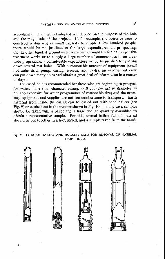
The cased hole is recommended for those who are beginning to prospect for water. The small-diameter casing, 4-10 cm (2-4 in.) in diameter, is not too expensive for water programmes of reasonable size; and the neces- sary equipment and supplies are not too cumbersome to transport. Earth material from inside the casing can be bailed out with sand bailers (see I Fig. 9) or washed out in the manner shown in Fig. 10. In any case, samples should be taken with a bailer and a large enough quantity assembled to obtain a representative sample. For this, several bailers full of material should be put together in a box, mixed, and a sample taken from the batch.
Fig. 9. TYPES OF BAILERS AND BUCKETS USED FOR REMOVAL OF MATERIAL FROM HOLES

66 WATER SUPPLY FOR RURAL AREAS
When the casing is being washed or jetted down, the problem will be to decide when and how to take samples. The reason for this is that the water jet causes the separation of the fine- and coarse-ground materials, and it takes a great deal of experience to tell much about the strata from which these materials came.
Fig. 10. HYDRAULIC METHODS OF EXPLORATION
Jetting Method Hydraulic Method Hollow Rod Method
Reproduced from Bennison, E. W. (1947) Ground water: its development, uses and conservation, p. 99, b y kind permission of Edward E. Johnson, Inc., St Paul, Minn., USA

INSTALLATION OF WATER-SUPPLY SYSTEMS 67
For small wells, therefore, samples should be taken every 2 m (6% ft) or so; but, once the water table is reached, samples should be taken more often. The water-jetting bit can be raised and samples taken with a bailer or, preferably, with an auger. It should be kept in mind that most well- prospecting holes for rural water-supplies will be less than 100 m (330 ft) in depth and that the average test hole will probably be around 50 m
1 (165 ft) deep. Therefore, the additional manipulation of tools involved in taking ground samples (i.e., the changing, raising, and lowering of tools) in I most instances will not constitute a major loss of time in the construction of test holes.
Information can be obtained from uncased holes dug by small rotary drilling machines or by straight jetting of small-diameter pipes. The 1 Servi~o Especial de Saude Publica of Brazil has used jetting methods ex- tensively throughout the country and has put down thousands of holes in recent years. One of their best construction foremen has always preferred to jet with a 2-in. (55-mm) screen on the end of the jetting pipe. Then, when the water-bearing formation is penetrated, jetting operations are stopped, the screen is washed, and the well-hole is developed and tested for yield with a suitable pump. Where small quantities of water are requir- ed, this has proved to be a simple and highly economical procedure. More than half of the time this foreman has been able to obtain a quantity of water large enough to satisfy the objective of the project. Following 1 the tests, the screen and test equipment are removed, and a permanent
I well-installation is jetted down or specifications are given for construction at a later date. Application of this procedure, of course, requires much experience and a thorough knowledge of the geology of the area under investigation. There are many similar places in the world, however,
I
I where the same technique can be used with profit.
As samples are collected, careful notes should be kept regarding the depths at which they were taken and the number of feet or metres of the ground layers which they represent. The character of the formations, the presence of stones, boulders, etc., and the degree of difficulty of boring through them should also be noted.
Frequently the question is in doubt as to whether one should try for a permanent well out of the test-hole operation. The authors believe that, where conditions are fairly well known and the well-drilling crew is exper- ienced, it is certainly worth while to do so, as it is an economical procedure. In one area in Brazil, within a period of 16 hours a 30-cm (12-in.) casing
I and screen were jetted 24 m (81 ft) into a water-bearing stratum, and pro- i duced 2000 litres of water per minute when tested. The equipment required I consisted of two construction pumps of a capacity of 11 3 550 litres (30 000 US I gal.) per hour each. In this particular case, everything was known about
the ground strata from previous well constructions in the area, and it would have been of no avail to prospect further. As it turned out, this was a

WATER SUPPLY FOR RURAL AREAS
very economical operation. A highly productive well was sunk and testing started the same day. The knowledge required to make this feat possible, however, had been accumulated over many years.
Wells
There are three principal methods of well construction. Each method has its own advantages given certain conditions, and all three types and combinations of them are widely used under different circumstances.
The type of well most widely used throughout the world is the hand-dug well. Employing traditional methods, often identical with those used hundreds of years ago, aborigines in all parts of the world rely on open, hand-dug wells for their principal source of water. There are many Biblical references to well-digging, and there are wells in existence today which are believed to have been sunk in ancient times.
The use of modern materials, tools, and equipment has transformed the hand-dug well from a crude hole in the ground, uncertain in results, dangerous to its constructors and users, and the focus of parasitic and bacterial diseases, to a safe structure based on sound engineering prin- ciples, and a hygienic and reliable source of water. The hand-dug well is still one of the cheapest methods for providing a small supply of water for villages, but it is relatively expensive for the individual family. Although its construction is a rather slow process, it has many advantages which generally outweigh speed. The equipment used is simple and light, enabling sites remote from a road to be served; the process is easily taught to un- skilled workers, thus cutting supervision to a minimum; and, with the exception of cement and reinforcing steel rods (items relatively easy to transport), the materials used are usually obtainable locally. A further advantage in newly developing countries is that it adapts and improves on traditional methods of construction, which tends to increase the skill in other directions of those people trained in well-sinking. When com- pleted, the well provides not only a source of water, but also a reservoir enabling water which percolates into it at night to be drawn off during the day. Where demands are low, this property is of particular value, since weak aquifers with a low rate of flow into the well can be utilized.
Hand-dug wells naturally have certain limitations. While successful wells have been sunk in special circumstances to depths of over 120 m (400 ft), half that distance is usually considered the limit of practical sink- ing. For the installation of mechanical pumps designed to extract large quantities of water over long periods, the diameter of a dug well often has to be so large as to be uneconomical as compared with a bore-hole. Hard rock can be penetrated to a depth of a few feet (one metre or so) by the use of explosives; but it is extremely slow work; and, for consider- able thicknesses of rock, bore-holes are usually preferable.

INSTALLATION OF WATER-SUPPLY SYSTEMS 69
In rural areas, however, where a supply of a few hundred gallons per hour (such as can be drawn by buckets, hand, animal, or windmill pumps) is required from unconsolidated formations, the hand-dug well has so many advantages as to make it an almost invariable choice.
The drilled well, usually referred to as a bore-hole, has many advantages in other circumstances. Much greater quantities normally can be extracted
Fig. 11. DRILLING AND BORING METHODS OF EXPLORATION
?z SAND LINE
GROUND) SURFACE
, . . . . . . . Sand Bucket Method Auger Bucket Method Core Drill Method
Reproduced from Bennison, E. W. (1947) Ground wafer: its developmmt, uses and conservation, p. 104, by kind permission of Edward E. Johnson, Inc., St Paul, Minn., USA

70 WATER SUPPLY FOR RURAL AREAS
from a single hole, often making it the only practical method of supplying urban communities or other demands involving heavy pumping. Given good access roads over which the rig and casing can be moved easily to the site, the actual construction of the hole is usually a quicker operation than that of the hand-dug well although, when sites are widely scattered, the time consumed in moving the heavy equipment must be added to the construction time for a true comparison. Hard rocks can be penetrated to a considerable depth, although drilling in these hard formations naturally greatly slows operations. The most important advantage is the depth and rapidity with which a bore-hole can be drilled, the practical limit being governed solely by the size of the rig used (see Fig. 11).
For depths of more than, say 60 m (200 ft), therefore, particularly where large quantities of water are required, the bore-hole is the method usually selected. Under certain conditions it is possible to combine hand- dug and drilled wells to great advantage. Particularly is this so when a relatively small quantity of water is required for a village or hamlet and the only supply is a pressure aquifer lying too deep for hand-sinking methods. This condition is quite a common one in the tropics, and communities are usually small in areas where water is available only at a considerable depth. Costly bore-holes, of sufficient diameter to take pumps, are gener- ally an uneconomical proposition in these cases. But, if a hand-dug well is sunk and a small-diameter-i.e., 8-cm or 10-cm (3-in. or 4-in.)-bore- hole is inserted through the bottom of the well to a sub-artesian aquifer, then water will rise into the well throughout the whole 24 hours; and the well itself will act as a reservoir from which water can be drawn during peak periods.
The third method in general use is the tube well-a perforated or screened pipe which is jetted (jetted well) or driven (driven well) into a shallow aquifer. This may be a small-diameter casing fitted with a hand pump, or a large-diameter casing fitted with a mechanical pump. Properly constructed and under suitable circumstances, these tube wells can give surprisingly large quantities of water; but they are limited in the depths to which they can be inserted, and the ground formation must be appro- priate for their use. Their most common application in the tropics is for the extraction of water from water-bearing sands, especially those underlying the beds of ephemeral streams, and for making use of the natural filtering properties of sandy beds of perennial rivers by taking water from below the beds instead of from the rivers themselves.
In the following paragraphs, typical methods of well construction are described. It is obvious that no single method of oonstruction is applicable in all countries, regardless of geological and other field conditions. There are many other construction procedures in application in the world today, and it would be materially impossible to describe them all. Experience shows that it is often necessary for the field engineer to amend standardized
INSTALLATION OF WATER-SUPPLY SYSTEMS 7 1
procedures in the light of geological findings and to improvise tools and procedures which will help in speeding up the work.
Dug wells
When a big well-construction programme is to be carried out within a large rural area or country, it is of great importance that methods and equipment should be standardized as far as possible so that the initial training of the crews will enable them to build similar wells in different areas and under different circumstances without constant supervision. Certain features of the work must be adapted to different conditions-e.g., the thickness and reinforcement of the linings must vary according to the type of ground encountered, and the well intake (that part of the well through which the water enters) must suit the local conditions-but, in general, the basic methods, materials, and dimensions should remain as constant as possible.
In the past, wells have been constructed of circular and of square sec- tions; but the advantages of economy and strength are so overwhelmingly with the former that virtually all wells constructed now are circular in plan.
Diameter
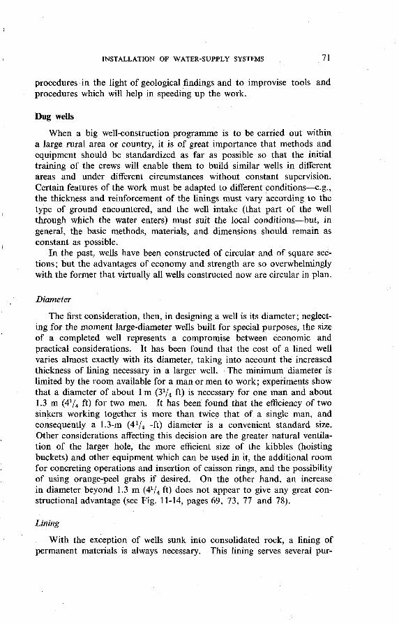
The first consideration, then, in designing a well is its diameter; neglect- ing for the moment large-diameter wells built for special purposes, the size of a completed well represents a compromise between economic and practical considerations. It has been found that the cost of a lined well varies almost exactly with its diameter, taking into account the increased thickness of lining necessary in a larger well. The minimum diameter is limited by the room available for a man or men to work; experiments show that a diameter of about 1 m (3l/, ft) is necessary for one man and about 1.3 m (4l/, ft) for two men. It has been found that the efficiency of two sinkers working together is more than twice that of a single man, and consequently a 1.3-m (4l/, -ft) diameter is a convenient standard size. Other considerations affecting this decision are the greater natural ventila- tion of the larger hole, the more efficient size of the kibbles (hoisting buckets) and other equipment which can be used in it, the additional room for concreting operations and insertion of caisson rings, and the possibility
I of using orange-peel grabs if desired. On the other hand, an increase in diameter beyond 1.3 m (4l/, ft) does not appear to give any great con- structional advantage (see Fig. 11-14, pages 69, 73, 77 and 78).
Lining
With the exception of wells sunk into consolidated rock, a lining of permanent materials is always necessary. This lining serves several pur-

72 WATER SUPPLY FOR RURAL AREAS
poses. It is a protection during construction against caving and collapse, it retains the walls after completion, and it also acts as a seal to prevent polluted surface water from entering the well, and enables the aquifer from which the supply is to be obtained to be isolated and protected from pollution. It acts as a foundation and support for the well-top and any pump or other mechanism which may be fitted on completion, and it serves as an impervious lining to the storage reservoir which such a well is designed to provide.
From both a practical and an economical point of view, it is better that the permanent lining be built into position as construction proceeds, thus avoiding the expense of temporary supports and the danger of collapse which may occur when the temporary work is removed to make way for the permanent lining.
The various ways of lining wells may be classified under two heads : those in which the wells are built into their final position as work proceeds, and caissoning methods, in which the lining is built above its final level and sunk as a completed unit to its final position. It will usually be found that a combination of these two systems will produce the most effective results.
There are many materials suitable for linings, masonry, brickwork, steel, and timber all being used in various parts of the world, according to circumstances; but for widespread use there are very great advantages in plain or reinforced concrete.
Masonry and brickwork are widely used in many countries and can be very satisfactory if conditiqns are right. In bad ground, however, they both suffer from having a low tensile strength, and unequal pressures can make them bulge or collapse. Building with these materials is slow, particularly in the confined working room of a well; and a greater thick- ness of wall is required than with concrete, as a result of which a corres- pondingly greater excavation is necessary. There is always a danger of movement during construction in loose sands or swelling shales before the cement has set; similar movement is prevented in a concrete lining by leaving the form in place to support the lining until the concrete has attained a high strength. Skilled masons, suitable stone, or well-fired bricks may not be readily available, whereas it is relatively easy to train unskilled workers to place concrete, and sand and gravel can usually be found within reasonable distance of a well site.
Steel linings are rarely used, because of their high cost, short life, and (except with very heavy sections) liability to bend. Timber is a most unsuitable material on account of its short life and its liability to rot, harbour insects, and taint the water. Also cross-members inside the well-necessary for strength-reduce the effective diameter; and it is almost impossible to make a lining sufficiently impervious, even when new, to keep out polluted surface water.

INSTALLATION OF WATER-SUPPLY SYSTEMS
Fig. 12. SECTION O F WELL SHAFT: FIRST LIFT
Scale : '1, in. = I ft

i 74 WATER SUPPLY FOR RURAL AREAS
Concrete, on the other hand, can be placed quickly by unskilled la- bourers, provided that they are adequately supervised; requires only a small thickness (8 cm, or 3 in., in good ground to a maximum of 12 cm, or 5 in., in bad); can be precast into caisson rings at the site, on the surface, in simple moulds; and makes a continuous, impervious lining, strong enough to support itself and any superstructure required. It adapts itself to the face of the excavation and can be made porous opposite the producing
I aquifer to act as an entrance screen.
Construction
Details of the equipment used and the sequence of operations in open well sinking are given in Annex 5, page 276. Briefly, the method of con- struction is as follows (see Fig. 12).
In normal ground (i.e., unconsolidated formations without any special hazards such as swelling shales or running sands) the shaft is sunk from ground level to the top of the aquifer by the method known as " alternate
I ~ sinking and lining ". The hole is excavated and trimmed to a diameter of 1.4 m (495 ft) and a depth of about 4.5 m (15 ft)-less if the ground is at all weak or if the ground-water level is less than 4.5 m (15 ft) deep. At that depth a curb or shoe is undercut into the side of the well about 30 cm (1 ft) deep all around; and, after the reinforcing rods have been placed into position, the section of the well is concreted by pouring behind
I I metal shutters, which are added one by one from the bottom of the excava-
tion as the lower section is filled. When this operation is complete, the result is a section of reinforced concrete lining 8 cm (3 in.) thick, 1.2 m (4 ft) in internal diameter, supported not only by its friction against the
I surrounding soil, but also on a reinforced concrete ring of 2-m (6%-ft) outside diameter.
Leaving the metal shutters in place, a further section of 4.5 m (15 ft) or less is excavated below the first and is in turn curbed and concreted, leaving 10 cm (4 in.) below the first curb to be hand-built with small con- crete blocks joined with cement and mortar. Sinking is continued in this way until the water-bearing strata are reached; and, in effect, the well now consists of a series of self-supporting cylinders from the surface to the aquifer, with an impervious joint between each.
From this depth onward the caissoning method is adopted. The caissons have been cast in moulds on the surface during the sinking and
1 lining operation and should now have attained their full strength. They consist of concrete cylinders each 61 cm (2 ft) high, 1.2 m (3 ft 10 in.) in external diameter, and 11 cm (4% in.) thick, with provision for four longi- tudinal bolts. These caisson rings are lowered singly into the lined ~ well, and each is fastened by four 16-mm (518-in.) diameter bolts to the ring below. A second cylinder is thus assembled vertically inside the

INSTALLATION OF WATER-SUPPLY SYSTEMS 75
first lining, but free to move downward as soil is excavated from below. One man only can work within the caisson ring, which has an internal diameter of 93 cm (3 ft 1 in.); and the depth to which the caisson can be sunk depends on the depth of water which cannot be removed by bailing. When the water-bearing formation consists of sand and gravel, or other loosely bound materials, pumps should not be used at this stage of the sinking since, if too much water is extracted, caving will almost certainly take place as the water-bearing materials are drawn into the well from outside the caisson. Even in a firm water-bearing stratum, it is important to avoid excessive pumping, which may produce similar results.
Obviously, with a large well-sinking programme, work must go on all the year round, and wells frequently have to be sunk when the water-table is high. All programmes should allow for deepening to take place when the water is at its lowest, and the method described above lends itself particularly to this. It is customary to leave a number of caisson sections projecting upward into the lined portion of the well so that in the dry season the team has only to continue excavation to the appropriate depth when the caisson drops into its final position.
Another advantage is the verticality of the caisson which follows auto- matically if the top lining has been plumbed properly, according to the method described in Annex 5, page 276.
According to the nature of the aquifer, a well may be designed to admit water either through the walls or through the open bottom. When the walls are used-and this is the more usual method-the caisson rings opposite the aquifer are made of porous concrete, which is described in Annex 5 (see page 294). In porous-walled wells the bottom is fre- quently concreted to prevent upward movement of soil and to facilitate cleaning.
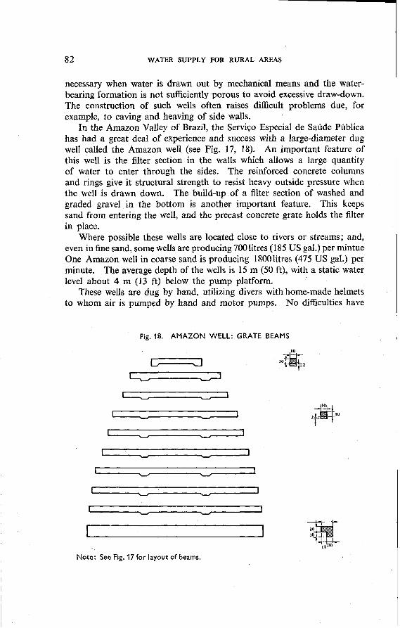
Occasionally, circumstances may make it desirable to draw water from the bottom only; an instance of this is when the aquifer is of very fine sand which would be drawn into the interstices of the porous concrete and either cause caving by the removal of the outside material, or clog the walls and prevent water from entering. In such a case, the caisson is made of normal concrete throughout; and, when the final depth has been reached, it is usual to place a filter of graded layers of gravel in the bottom to prevent the sand from being drawn upward into the well with the water. Requirements vary with circumstances, but a common gravel filter of this nature consists of 15-cm (6-in.) layers of 6-mm (%-in.), 10-mm (Y,-in.), and 12-mm ($$-in.) gravel, the smallest at the bottom, with about 8 cm (3 in.) of 20- to 25-mm (3/4- to 1-in.) gravel to protect the surface of the filter. Each layer is carefully placed by hand and levelled off before the next size is added. In addition to this gravel filter, it may be desirable to lay over the bottom of the well a precast concrete grate, as shown in Fig. 17 and 18 (see pages 81 and 82).

76 WATER SUPPLY FOR RURAL AREAS
A further purpose of this graded filter and the concrete grate is to reduce the " critical head " of the water in the well. This critical head is the maximum difference possible between the water levels outside and inside the well without movement of the aquifer particles. If it is exceeded, these particles are drawn in with the water, and caving can result. When a pump is fitted to the well, overdrawing (which means withdrawing water at such a speed that the critical head is exceeded) can be avoided by a proper positioning of the pump suction; but, with an open well when water is bucketed, it may be impossible to prevent the population from emptying the well completely if their needs demand it. When water is wanted from a level considerabb below the watertable, therefore, it is often desir- able to increase the thickness of the gravel filter described to prevent overdrawing.
In favourable areas, sub-artesian aquifers may be found. In such a case pressure water from the aquifer is forced up the well, and the standing water level is considerably higher than the point of entry. In these cir- cumstances it is usual to complete the whole well by the sinking and lining method without the use of caissons. Sinking stops once the top of the aquifer is reached; and, in order to avoid having unlined sections submerged by the rising water (which occasionally comes up very rapidly), the " lifts ", or lengths of sections between curbs, are kept very small once the aquifer is neared. Geological knowledge of the terrain and information from other wells in the vicinity will usually allow the depth of such aquifers to be estimated fairly accurately. A graded gravel filter in the bottom of a well with a sub-artesian rise will usually be found of value.
Procedure for shallow wells (in jirm ground formations) : Another pro- cedure which is commonly used in many parts of the world for the cons- truction of shallow wells may be briefly described as follows :
(1) The hole is excavated to the desired diameter and depth, or to a point where the ground appears unstable and cribbing becomes necessary in the hole to support the walls. In loose soils, dug wells must be cribbed in order to protect the men who are working inside the well. Cribbing material can be rough lumber and logs cut from any wooded area. Tight cribbing helps to keep out the ground water, allowing the well to be dug deep into the water-bearing formation.
(2) The material excavated is placed in boxes or buckets and pulled out with ropes from above. Usually one box or bucket is being emptied while another is being filled.
(3) When water is reached, it will be necessary to bail the water out of the well along with material excavated. The more efficiently the well is kept dry (of course, within the limitations mentioned in the preceding paragraph), the deeper it can go into the ground water and, therefore, the more water it will give.

INSTALLATION OF WATER-SUPPLY SYSTEMS 77
Fig. 13. DUG WELL WITH PROTECTIVE CASING A N D PLATFORM
This figure shows a dug well and an outside protective cover of concrete. A t the well bottom are t w o different types of construction; one, built-up, round stones offering a f i l ter wall, and the other, a concrete shoe. Stones must be laid up after the well is com- pletely excavated, and are practical only in areas of coarse sand and gravel. The concrete shoe is employed where the well casing is sunk as the excavation progresses, and is usually more practical in fine sand. A protective, graded sand fi l ter should be built up in the bot- tom of this well.

WATER SUPPLY FOR RURAL AREAS
Fig. 14. DUG WELL LINED WITH CONCRETE OR CLAY TILE
TJ
WHO 5222
Concrete o r clay tiles make excellent well casing and can be placed quickly and easily into the well by the use of a simple A-frame o r other temporary structure for lowering ti le into a well. Note the outside, protective layer of concrete which extends down t o 3 m (10 ft) minimum t o ensure water-tightness of the upper walls.

INSTALLATION OF WATER-SUPPLY SYSTEMS 79
Fig. 15. RECONSTRUCTED DUG WELL WITH BURIED SLAB
CLOSED TOP PUMP
No*: Concrete well platform to be loid o f tn backfill har suHiciently
Noto: settled Pump rbnd and bore must be in one ptoce, joined by Bonged or
Weep hole to be placed
threaded connection below frost depth to provide on antsbeeze instollotion
Cylinder Tp Be Ploced Below Point of Moximvm Draw-down
Embed in concrete one Excavate and remove
or two strapiron caring old curbing to point
clompr of ruHicient not Ierr than 10 foot
rtrongth and sire to from surface whore
rigidly support caring existing curbing is found to be solid.
provide proper watertight (oundotion for cap
Reproduced from US Public Health Service, Joint Committee on Rural Sanitation (1950) Individual nsater supply systems, Washington, p. 25

80 WATER SUPPLY FOR RURAL AREAS
(4) When the deepest possible point of excavation is reached, round stones should be laid around the wall (see Fig. 13) to form the first 0.5- 1 m (20-40 in.) of well casing. Brickwork is built up to the top of the well, with extra heavy wall for the top 3 m (10 ft), well grouted to provide waterproof casing.
(5) To finish the well, either a bailing apparatus or a hand-pump and platform is installed, as shown in Fig. 13-15.
Procedure for deep-dug wells: Where wells are deep, the complication of cribbing and the danger of caving are great, so that the masonry casing is usually started after the excavation is about 5-6 m (16-20 ft) deep. It is built up to ground level and maintained there; from then on, it descends under its own weight as excavation continues (see Fig. 16). This system gives protection to those working in the well.
Fig. 16. DUG WELL: CASING DESCENDING WITH EXCAVATION
A = Reinforced-concrete shoe B = Concrete or masonry casing
Large-diameter dug wells
Large-diameter dug wells are usually very shallow, 15-20 m (50-65 ft), and are built in order to provide large water-storage capacity. This is

INSTALLATION OF WATER-SUPPLY SYSTEMS
Fig. 17. AMAZON WELL
4 0
CROSSSECIMN A- A CROSS-SECTION
E I D-D
, The scale used is in cm.
A - E = Cross sections F = Reinforced-concrete shoe G = Hollow bricks laid sideways. Water enters the
filter section I through the holes in the brick. H = Hollow bricks laid flat. Water enters the well
through small holes designated by L. See detail H and F.
I = Sand fi l ter section between brick walls
J = Height of filter section, varies w i th depth of penetration in to ground water
K = Reinforced-concrete beams L = Small perforations through bricks H. See detail F.
M = Layer of round stones N = Layer of gravel ,
0 = Layer of coarse sand P = Iron steps, 50 cm (20 in.) apart Q = Grate made of concrete beams (see fig. 18)
82 WATER SUPPLY FOR RURAL AREAS
necessary when water is drawn out by mechanical means and the water- bearing formation is not sufficiently porous to avoid excessive draw-down. The construction of such wells often raises difficult problems due, for example, to caving and heaving of side walls.
In the Amazon Valley of Brazil, the Servi~o Especial de Sadde Pdblica has had a great deal of experience and success with a large-diameter dug well called the Amazon well (see Fig. 17, 18). An important feature of this well is the filter section in the walls which allows a large quantity of water to enter through the sides. The reinforced concrete columns and rings give it structural strength to resist heavy outside pressure when the well is drawn down. The build-up of a filter section of washed and graded gravel in the bottom is another important feature. This keeps sand from entering the well, and the precast concrete grate holds the filter in place.
Where possible these wells are located close to rivers or streams; and, even in fine sand, some wells are producing 7001itres (185 US gal.) per mintue One Amazon well in coarse sand is producing 18001itres (475 US gal.) per minute. The average depth of the wells is 15 m (50 ft), with a static water level about 4 m (13 ft) below the pump platform.
These wells are dug by hand, utilizing divers with home-made helmets to whom air is pumped by hand and motor pumps. No difficulties have
Fig. 18. A M A Z O N WELL: GRATE BEAMS
Note: See Fig. 17 for layout of beams.

INSTALLATION OF WATER-SUPPLY SYSTEMS 83
been encountered in this method of construction except that it is slow, because digging under water is not very efficient, and the tremendous resistance between the soil and the casing keeps the latter always above the excavation, thus causing a great deal of sand to run into the well. In the end, several times the volume of the well is excavated. Jetting around the bottom of the well has given promise of facilitating the sinking of the casing. Mechanical excavating equipment would also speed up the excavating process. This well is relatively cheap where cement, reinforcing steel, and bricks are available and, of course, where a water-bearing sand is relatively close to the surface.
The yield of the large-diameter dug well can be increased considerably by developing a gravel pocket around the bottom filter section and by constructing laterals out from the well. This is accomplished by pumping large quantities of water into the well; it will soon begin to bubble up around the outside walls, and then graded gravel and coarse sand can be introduced all around the well. Large quantities of material are needed. While this is sometimes a laborious process, it is usually well worth the cost.
Extending laterals out from the well into the water-bearing strata is an excellent method of increasing its yield (see Fig. 19). For small works a heavy automobile jack can be used, but proper machines are available on the market for this purpose. These machines are also used for putting pipes under roads, buildings, etc., without disturbing the surface. A combination of jacking and jetting can be employed in one operation with advantage. Perforated pipes up to 15 cm (6 in.) in diameter, preceded by a drive point, and by a screen if desired, may be installed in this manner. Once the lateral is in place, provision should be made for developing the aquifer in its vicinity, and forperiodic backwashing of these pipes. Laterals can be placed at various levels depending upon the characteristics of the water-bearing encountered. The construction of large installations of this type requires considerable judgement and engineering experience, and should not be attempted without consultation with competent hydraulic (water) engineers in central government public works administrations or specialized engineering firms.
Driven wells
Driven wells are constructed by driving into the ground with a hammer a pipe at the lower end of which a drive-well point has been attached (see Fig. 20,21). These wells are usually from 2.5 cm to 10 cm, most commonly 3 cm (from 1 in. to 4 in., most commonly 1% in.). in diameter. On account of the ease with which these wells can be driven, pulled out, and put down again elsewhere, they are very popular in many parts of the Western Hemi- sphere, South-East Asia, and the Orient.

WATER SUPPLY FOR RURAL AREAS
Fig. 19. LARGE WELL WITH HORIZONTAL PERFORATED PIPES
A = Stream o r pond B = Water-bearing formation, gravel o r
sand bank C = Impervious stratum D = Large-diameter well E = Collection pipes (horizontal wells)
headed by drive heads and provided wi th sections o f perforated pipes. Lengths of these pipes t o be decided after tr ial holes t o see how far the gravel bank extends
F = Control valve G, H = Connexions t o receive hose from
outlet H for backwashing collection pipes and for development purposes
I = Rising mains, pumps and motors J = Check (non-return) valve K = Valve controlling discharge of pipe
leading t o reservoir L = Washout valve

INSTALLATION OF WATER-SUPPLY SYSTEMS 85
Fig. 20. DRIVEN WELL WITH DROP-PIPE A N D CYLINDER A N D PROTECTIVE PLATFORM .
. . _ . -
WHO 52j0
In areas wi th relatively coarse sand, driven wells can be an excellent and very cheap means of obtaining water. They can be driven rapidly and put into operation quickly. W i t h proper technique, this well can be developed t o increase its capacity. Note the water-tight casing which extends down t o a minimum of 3 m (10 ft) below ground surface.

WATER SUPPLY FOR RURAL AREAS
Fig. 21. TYPICAL WELL POINTS
A = Common type of screen for well point. It is reasonable in cost and, in a good water- bearing formation, it can give good results. Over-pumping is apt t o plug up the screen.
B = An effective type of well point. It wi l l not plug easily but is more expensive than common screens. W i t h proper development, large quantities of water can be obtained through such well points.
They cannot be put in hard, solid stone or hard-pan strata, or in heavy beds of clay; but they can be successfully driven through compact soils and even through chalk. As in the case of bored wells, when boulders and rock are met it is best to pull up the pipes already in the ground and to try a new spot a little distance away.
The depth of ground water is another important consideration in the I selection of driven wells in a given locality. In individual installations where the ground water is very shallow, say within 7.5 m (25 ft) of the 1 ground surface, the pump cylinder is usually attached directly to the top I
of the rising pipe. The total depth of such wells seldom exceeds 10-15 m 1
(33-50 ft). For larger installations and under similar circumstances, a i
well-point system, designed as shown diagrammatically in Fig. 22, can deliver relatively large quantities of water from a shallow aquifer.

INSTALLATION OF WATER-SUPPLY SYSTEMS
Fig. 22. WELL-POINT SYSTEM
B
+ - A
. . \ rC-
I
WHO 5231
A = Well points properly spaced so that there is no interference between their circles of influence
B {= Pumping header with allowance for future expansion in both directions C = Pump D = Priming line E = Water table F = Draw-down
Equipment and tools
Driving equipment and tools are simple and easy to operate. A typical set for driving 3-cm (1 %-in.) pipe includes :
Equipment
15 m (50 ft) of 3-cm (1%-in.) wrought-iron pipe, extra heavy, with couplings provided 1 pitcher-spout pump, tapped for 3-cm (1%-in.) pipe 1 drive-well point, 3 cm (1% in.), with jacket length 1.2 m (4 ft), with openings smaller
than 0.4 mm (about 1/100 in.)

88 WATER SUPPLY FOR RURAL AREAS
1 pulley bar, 3 cm x 1.4 m (1% in. x 4% ft), approximately 1 driving monkey, 35-45 kg (80-100 lb.) 15 m (50 ft) of cleaning-out tubes, 1.3-cm (%-in.) diameter, in assorted lengths 1 pair of driving clamps, 3 cm (1 1/4 in.) 9 m (30 ft) of 2-cm (%-in.) manila or cotton rope 1 plumb bob, line and winder, 15 m (50 ft)
Tools 1 pipe cutter, 0.3-5 cm ($&-2 in.) 1 adjustable screw spanner, 25 cm (10 in.) 1 chain wrench, 0.3-3.8 cm (%-I% in.) 1 25-cm (10-in.) file 1 set of stocks and dies, 1.3-3 cm (%-I% in.) 1 pipe wrench, 1.3-5 cm (95-2 in.), 46 cm (18 in.) long 1 side-cutting pliers, 20 cm (8 in.) 1 adjustable end-wrench, 25 cm (10 in.) 6 screwdrivers, assorted sizes 1 hammer, machinist, 340-g (12-oz.) weight 1 8-m (25-ft) flexible steel measuring tape 1 1.5-m (5-ft) crowbar, wedge point
Spares and miscellaneous 1 pipe cap, 3 cm (1 1/4 in.) 1 driving cap, 3 x 8 cm (llh x 3 in.) 2 spare cutting wheels for pipe cutter 1 3-cm (1 %-in.) plug tap 1 3 x 1.3 cm (1 '/4 x 1/2 in.) reducing socket 1 tin of red lead, 1 kg (2 lb.)
For driven wells 3 cm (1 $4 in.) in diameter and 15 m (50 ft) deep, the cost of the above equipment would be approximately US $325 in 1958 in North America or Western Europe. This price is given, as a rough indi- cation only, for engineers and administrators contemplating a programme of construction of such wells.
Technique
Although the methods used for driving wells vary considerably in their details, a typical technique of installation may be briefly described as follows.
The driving clamp is fastened to the drive point or perforated pipe. The monkey or hammer is slipped on to the pipe above the clamp, and the pulley bar is inserted in the pipe. A rig made of local wooden or bamboo poles may be set up for holding the pipes in a vertical position. A small hole 50-80 cm (20-32 in.) deep is dug in the ground by means of a crowbar at the selected spot.
Driving begins by pulling on the ropes, raising the monkey and, then, letting it fall on the clamp. Care must be taken at all times to keep the pipe vertical. This may be checked by means of a plumb line. When the

INSTALLATION OF WATER-SUPPLY SYSTEMS 89
clamp reaches ground level, driving is stopped; the clamp is loosened and raised about 30 cm (12 in.) if the soil is hard, 50-60 cm (20-24 in.) if driving is easy through soft soil; and operations are resumed. When the first pipe has penetrated the ground to such a depth that there is no more head- way for the monkey to work, a new length of pipe is added. To ascertain whether water has been reached, the plumb line is frequently lowered in the pipe. This also helps to determine whether earth or sand has penetrated to any appreciable extent in the pipe through the screen or perforations. When this happens, the dirt may be removed by means of the small cleaning- out tubes and a hand-pump.
After the water-bearing stratum has been reached, it is advisable to continue driving operations to such a depth that the well will never dry up, even in dry seasons. The pump may then be installed and the well com- pleted.
To start the pump, it is necessary to fill the suction column with clean water and to exhaust the air which is in it. The water coming out of the well will be muddy at first, but will clear up after an hour or so of vigorous pumping.
In order to ensure a steady flow of water in the future, it is necessary to " open " the water-bearing formation in the vicinity of the drive point by removing its content of fine earth or sand particles. When the ordinary pitcher pump is used, this may be achieved by raising the handle high for a brief moment, thus allowing the water in the suction column to drop sud- denly, and then resuming the pumping immediately and vigorously. With this sudden drop, the pipe's water rushes out of the screen at the bottom of the well and shakes and disturbs the fine particles surrounding the pipe. Such action facilitates the removal of the fine particles when pumping is resumed, as the well water will be seen to remain muddy for a while. This process should be repeated several times before the well is considered to have been completed.
Various other methods may be used for developing or finishing wells in sand and gravel formations. One of the simplest and most common methods is over-pumping, i.e., creating a draw-down much in excess of that which will be maintained in future operation. This system, while not fully effective as a development procedure, has the advantage of clearing fine particles from the well and its immediate surroundings and of providing useful data with respect to the capacity of the well. It may be used only on small, low-capacity wells driven into fairly well-graded formations. Over-pumping should not be done and may even be detrimental when the formation is uniformly fine and made of silt or clay, because it may result in considerable caving of the ground surrounding the well. Other methods of development, using compressed air, surge plunger, or back-washing, require study and much experience on the part of the driller or engineer, and should not be attempted lightly.

90 WATER SUPPLY FOR RURAL AREAS
It is sometimes necessary to lift the pipes or to withdraw them completely from the ground. This happens, in the first instance, when they have been driven by mistake beyond the water-bearing stratum. In other cases, the soil may prove too compact, or boulders may have been encountered. Finally, no water may have been found within the permissible limit.
The pipe can readily be withdrawn by disassembling the monkey and pulley bar. By means of a crowbar or strong wooden log passed below the clamp and used as a lever, it is possible to pry the pipe out of the ground. The monkey may also be used in a reverse direction for the same purpose.
Jetted wells
With a small amount of pumping equipment, it is possible to sink wells to considerable depths very rapidly by the jetting method. Depending on the soil and the amount of water that can be pumped, a fairly large-diameter casing of 25-38 cm (10-15 in.) can be sunk 50-100 m (160-320 ft), thereby making it possible to install larger screens and pumps. Jetting is highly recommended for exploration and for small tube-wells, provided that plenty of water is available for sinking.
Small-diameter wells
The system of jetting as used in India for small-diameter wells and described very well by Bose a has given excellent results. It is summarized below.
Equipment :
(1) Tripod of bamboo with 8 m (25 ft) of clearance (2) Hand-operated lift and force pump (double-acting, with plunger
10 cm (4 in.) in diameter) (3) 4 chain-type wrenches for gripping pipes (4) 12 m (40 ft) of high quality hose, 3.8-cm (1 %-in.) diameter (5) Casing pipe, boring pipe, a swivel joint, steel cutter, pulley ropes,
small hand tools. For small jetted wells, 61 m (200 ft) deep, for example, excluding casing
pipes which belong to the wells themselves, the cost of the above equipment would be approximately US $1100 in 1958 in North America or Western Europe. This price is given, as a rough indication only, for engineers and administrators contemplating a programme of construction of such wells.
a Bose, P . C. (1953) Water-supply systems in rural areas, with special reference to West Bengal, India. (Unpublished working document WHO/Env.San./36)

INSTALLATION OF WATER-SUPPLY SYSTEMS 91
The jetting process :
(1) Dig a hole 1.5 m (5 ft) deep over.which the tripod is mounted; this gives a reasonable starting depth.
(2) Attach the cutter to one end of a 3.8-cm (1%-in.) boring pipe, usually about 6 m (20 ft) in length; swivel to other end and place cutter end of pipe into the hole; suspend the pipe and swivel with pulleys from the tripod (see Fig. 23). The swivel joint allows water to enter the boring
Fig. 23. TUBE-WELL BORING BY WATER-JET SYSTEM
A = Wooden tripod G = Hose B = Bracing H = Life and force pump C = Pulley I = Operating handle D = Rope J = Suction E = Chain pipe wrenches K = Water reservoir F = 38-mm- (I1/,-in.-) diameter tube-well L = Surface drain

92 WATER SUPPLY FOR RURAL AREAS
pipe from the hole while, at the same time, permitting the boring pipe to revolve without leaking.
(3) The hose is attached to the force pump which pumps water from a sump excavated in the ground near the well. (The pump suction pipe must be held clear of the bottom and sides to avoid sucking up mud and sand.)
(4) Jet-boring starts as the pumpers begin to force water into the boring pipe, at which point the men with the chain wrenches begin to turn the pipe.
(5) With the pressure of the water and the twisting action, the bore pipe begins to descend, and the jetted water begins to boil up around the sides of the bore pipe. This water is full of suspended matter and is really a light mud. (The more water that can be pumped through the pipe, the faster it will descend and the more and larger will be the suspended matter being washed out of the hole.) In a short time the first 6-m (20-ft) length of pipe will be at ground level. The swivel is removed; a second length of bore pipe is screwed on; the swivel is attached to this new length of pipe; and the pumping, jet-boring process begins again.
(6) One after another, the bore pipes are sunk until the desired depth is reached. This can be ascertained by examining the borings that are coming out of the well. In West Bengal the water-bearing stratum is a fairly fine sand with an effective size of from 0.16 mm to 0.20 mm. When this stratum is reached, boring is stopped; but pumping continues at that level for some time to clean the whole well.
(7) Jetting water is re-used by letting the dirt and sand settle out in the sump.
Placing the screen :
(1) The entire column of jet-boring pipe is now removed and the cutter is taken from the end of the bottom pipe.
(2) The well screen is now attached to the first length of well pipe, and the process of lowering the pipe is repeated with pumping, but through the screen. (Naturally there is little resistance in the recently jetted hole.) The screen is open at the bottom; and, when it is in the position desired, a pre-seated plug made of lead is dropped into the pipe and closes the hole at the bottom of the well screen, sealing the bottom of the well. A well point with a closed end may also be used, although sometimes a few feet of hole may be lost while raising the jet and lowering the well point.
At this stage of the process, when water is being pumped down through the well pipe and screen, washed pebbles can be dropped into the hole around the outside of the well pipe. These are heavy enough to settle even against the upward stream of water, and the stream can be regulated to allow settlement. These pebbles of round, washed gravel, from 1 mm to 4 mm in size, help to form a gravel pack around the well, thus reducing the possibility that fine sand may get packed up around the screen and enter the well, with a consequent cutting-down of capacity. It should be added

INSTALLATION OF WATER-SUPPLY SYSTEMS 9 3
that, where sufficient sand-free water is being obtained without the attempt at gravel packing, the methods that have proved successful should be followed. Where trouble is encountered in getting water from fine-sand strata, it will be worth while to experiment with gravel packing. It is highly important that round, selected, washed material be used.
(3) A 2-cm (%-in.) pipe is now lowered into the well pipe to the bottom, and a strong jet is pumped. This is done to clean the inside of the well pipe and screen off any possible sediment, sand, or dirt.
Finishing the well :
(1) The space between the well pipe and the earth hole should be back- filled with compacted clay or concrete to prevent contamination from reaching the water table through this space.
(2) The well is now complete, and the hand-pump is installed and operated continuously for (at least) eight hours per day for three days to clean out the jetting water.
(3) A little hypochlorite should be introduced into the well, allowed stand for 24 hours, and then pumped out again.
(4) A watertight platform should be constructed to complete the well.
Jetting large-diameter casings
When casings 10 cm (4 in.) or larger are to be jetted, a tower such as that shown in Fig. 24 may be built of local, rough lumber; but, if many wells are to be constructed, a lumber or metal tower that is dismountable may be advantageous. If possible, the tower should be built as high as the length of the well casing so that, once the jetting operation starts, it will not stop until the casing is at the desired depth. This is very important because, as long as the casing continues to go down, no difficulties are encountered; but, once operations stop, it takes a tremendous surge of water and agi- tation to start the casing down again. This is especially true with casings 15 cm (6 in.) and larger. It has been found worth while and economical to build a high tower just to avoid stopping in the middle of the jetting operations to splice on more casing. Naturally there is a limit to the height of the tower. The problem of sticking casings of less than 15 cm (6 in.) is not so great, and the expense of a high tower is probably not justified for these sizes.
A large quantity of water is necessary; and, the larger the casing, the more water is needed. When one pump is not enough, more than one can be used in tandem. This type of construction must be carried out, therefore, near streams or rivers or other bodies of water. The use of sumps for settling out the heavier suspended material is a practical solution when only a limited quantity of water is available (Fig. 25).

WATER SUPPLY FOR RURAL AREAS
Fig. 24. JETTING A LARGE-DIAMETER CASING (I)
A = Hose or pipe to ample supply of water B = Large-capacity, portable, centrifugal pump C, D = Hose to swivel joint and casing D = Well casing E = Block and tackle (size depends on weight of casing and hose) F = Rope to block and tackle
First, a hole is augered into the ground about 1.5-2 m (5-6% ft) deep at the point where the pipe is to be sunk. This is done to get the casing started. If the area is new and nothing is known about its geological features, a 5-cm (2-in.) pipe' is jetted down to open up the ground formations and to collect samples. When the well depth is determined, the 5-cm (2-in.) pipe is removed, and a 15-cm (6-in.) casing and screen with a ball check

INSTALLATION OF WATER-SUPPLY SYSTEMS
1 Fig. 25. JElTlNG A LARGE-DIAMETER CASING (I!)
W i t h ample pump capacity and water, 10- t o 20-cm (4- to 8-in.) screens can be readily jetted to depths of 50 m (164 ft) o r more in unconsolidated formations. This system is especially practical in broad river valleys o r near streams.
I valve are placed in position. The pump is started, and the casing usually goes down quite readily. It may be necessary to hold the pipe slightly off the bottom of the hole in order to get the jetting operation started. This reduces bottom resistance, and less water goes out through the sides of the screen. When the desired point is reached, the pumping continues and a gravel pocket is developed around the screen. As the water rises around the outside of the pipe, fine gravel and coarse sand are put in the annular space on the periphery of the casing. This material goes to the bottom

96 WATER SUPPLY FOR RURAL AREAS
of the hole and begins to fill the void between the screen and the sides of the hole. As more material is put in, resistance to the rising water is increased; and, finally, the water will rise so slowly that no more fines are washed out. From then on, pumping is begun with a test pump to clean out the well and measure capacity. Surging might be required if the water-bearing stratum requires further development. This would allow more fine particles to pass through the screen. If the capacity is adequate, the annular space around the well casing is filled with sand up to a point 4 m (13 ft) from the surface; and a protective casing is placed in the top 4 m (13 ft).
If the pumping test proves the well to be inadequate, the casing and screen are removed. This is done by use of two auxiliary pipes of 2-cm or 2.5-cm (%-in. or 1-in.) diameter which are jetted down on each side of the casing to the bottom of the hole. When this point is reached, pumping through the screen casing is begun. With a chain hoist pulling on the casing, the latter will usually come loose; and, from then on, the regular hoist will be able to complete the job of pulling it out. The pumping con- tinues until the casing and screen are completely removed. Auxiliary jets can usually be stopped once the casing starts to move upwards.
Equipment
Pump, 8-cm (3-in.) discharge outlet, capacity 75 700 litres (20 000 US gal.) per hour against zero head
Extra strong, reinforced hose, 8 cm (3 in.) Foot valve, 8 cm (3 in.) Cutting bit for hard material Fishtail bit Swivel, 8 cm (3 in.) A frame or tripod with winch and cable or tower Pipe wrenches Chain tongs Clamp to hold pipes Chain hoist Hammer, 3 kg (6.6 Ib.) Small tooh for engine and pump maintenance Grease gun Soil sample kit Steel tape, 30 m (98 ft) - Small electric water-level indicator Pipe-threading dies for sizes used Hack saw with extra blades Files for repairing threads of casing 15-cm (6-in.) auger to start holes Shovels, picks, and tools for clearing Wood blocks and planks for levelling and securing pumps and engines Casing

INSTALLATION OF WATER-SUPPLY SYSTEMS
Material
2.5-cm (I-in.) pipe for auxiliary, etc. Fittings for 2.5-cm (1-in.) jet : two long-radius elbows, two couplings, one reducer
8 x 2.5 cm (3 x 1 in.) 2 valves, 8 cm (3 in.) Fittings to hook two pumps in tandem Well screens of various slot sizes, with jetting valves Gasoline, oil, grease
I For jetted wells 15 cm (6 in.) in diameter and 61 m (200 ft) deep, for example, the cost of the above equipment would be approximately US $3800 in 1958 in North America or Western Europe. This price is given, as a rough indication only, for engineers and administrators contemplating a programme of construction of such wells.
1 Selection qf screen
The purpose of a screen is to permit ground water to flow with a mi- nimum of resistance into the well hole while at the same time excluding fine sand. A good screen will pass up to 70 %-80 % of the water-bearing sand grains into the well. This statement does not apply, however, to sand formations of uniform size such as are often found in many areas of the Amazon Valley of Brazil and elsewhere.
Since the life span of a driven well is governed by the quality of its screen, it is important to select a screen not only because of its hydraulic characteristics, but also because of the quality of the alloy of which it is made. It is first necessary to make a sieve analysis of the water-bearing formation and to determine its thickness. From these data it will be possible to specify the size, shape, and number of screen openings, as well as the diameter and length of the screen desired, liberal allowance being made for loss of capacity and reduced life span due to incrustation or corrosion and to partial clogging of openings. Finally, the metal of which the screen is made should not be vulnerable to attack by the chemical action of the ground water or by the acids sometimes used to remove incrustations from such screens.
Bored wells
A simple method of construction of small-diameter wells of shallow depth is the use of an earth borer, also called earth auger (see Fig. 26, 27). First, a small hole 30-50 cm (12-20 in.) deep, and of sufficient diameter to allow the introduction of the borer, is dug in the ground with,an ordinary pick or crowbar. From then on, boring proceeds to the desired depth.

98 WATER SUPPLY FOR RURAL AREAS
The shape of the spiral allows the loosened soil or gravel to rise upwards. From time to time, the borer is raised out of the hole together with the soil extracted.
Fig. 26. TYPICAL BORING TOOLS
A = Tool for boring in top soil, clay, sandy clay, o r formations that are not too hard o r caving. Cutter (a) may be added t o permit boring up t o 8 cm (3 in.) wider than standard size
B = Spiral auger C = Regular club b i t for breaking through hard formations, loosening rock, and breaking
soft rock D = Tool for boring in soft, wet, sandy soils
The limitations of this method, which is usually a hand operation, are obvious. When hard underground formations, such as rock or stone, are encountered, boring is stopped and a new spot selected several metres away. This method is especially adapted to soft soil, chalk, limestone,

INSTALLATION OF WATER-SUPPLY SYSTEMS 99
Fig. 27. BORED WELL WITH PROTECTIVE CONCRETE CASING A N D PLATFORM
A = Clay t i le lining, 10-15 cm (4-6 in.) in diameter B = Protective concrete lining C = Pump cylinder D = Standing water level in well
Where soil is sandy o r clay wi th no large boulders o r hard rock formations, wells may be bored t o considerable depths. Bored wells are reasonable in cost and can produce good results.
I
I and alluvial formations which are devoid of large gravel and stones and can be easily penetrated.
1 Several accessories to the earth borer have been designed by manufac- I turers to facilitate boring, especially in soils containing either wet sand or
loose gravel. Some of them are shown in Fig. 26. A typical set of boring tools for wells of 10-cm (4-in.) diameter or less
includes :

100 WATER SUPPLY FOR RURAL AREAS
1 drill, 10-cm (4-in.) diameter 1 one-piece 10-cm (4-in.) drill and deep-boring attachment 1 T-handle 15 m (50 ft) of steel rods for 10-cm (4-in.) drill 1 sand borer, 10-cm (4-in.) diameter 1 spiral point 1 chisel, 9-cm (3%-in.) 1 twist drill 2 extension cutters, for 10-cm (4-in.) drill One complete set of boring equipment and tools for wells 15 m (50 ft) deep
and 10 cm (4 in.) in diameter, including 10-cm (4-in.) pipe lining, would cost approximately US $300 in 1958 in North America or Western Europe. This price is given, as a rough indication only, for engineers and admini- strators contemplating a programme of construction of such wells.
Because of the rough handling and use to which the equipment is usually subjected in the field, a liberal number of spare items should always be at hand.
Once the hole is completed and the water-bearing stratum deeply pene- trated, small-size pipes with screen or strainer attached are lowered into the hole, the pump is installed, and the well is completed by the construction of an adequate platform and the provision of drainage for surface water.
When the soil is so soft that it frequently caves in, pipes of a diameter equal to-or 1.3 cm (% in.) larger than-the borer's nominal size are lowered as boring proceeds. The borer is passed inside the pipe and is provided with movable side (or extension) cutters (see Fig. 27, page 99) capable of cutting a hole 3.8 cm (1 1/2 in.) wider in diameter than the borer, to allow the pipes to follow the borer as it descends.
In some parts of the world it is not uncommon to bore wells to 90-cm (36-in.) diameter, using a team of horses and' augering equipment designed for such purposes.
Drilled wells
In this monograph, the term "drilled well " indicates that which is constructed with machines designed and manufactured for the purpose of drilling water wells. These machines can be described as being of two general types : (1) the percussion, and (2) the rotary.
The percussion drilling rig, also known as the " cable taol " rig, is the more common and more simple (see Fig. 28). It consists of a derrick and hoisting and control equipment, skid-trailer or truck mounted. The derrick serves as the elevated structure from which the drilling tools, well casing, screens, and all materials and equipment used in, or to construct, the well are suspended and manipulated. These rigs vary from the very small sizes to those which drill more than 1000 m (3300 ft).

INSTALLATION OF WATER-SUPPLY SYSTEMS
Fig. 28. PORTABLE WELL-DRILLING RIG
Reproduced from Bulletin 20-W-2 by kind permission of Bucyrur-Erie Co., New York, N.Y., USA.
Such drills can be transported on 1 )/,-ton trucks and may be used for holes frcm 7.5 c n to 15 cm (3-6 in.) in diameter and up t o 115 rn (377 ft) in depth.

102 WATER SUPPLY FOR RURAL AREAS
While all percussion rigs work on basically the same principle, i.e., the chiselling action of a tool alternately raised and dropped in a bore-hole, rotary rigs are much more varied in construction and operation, though all have the common feature that the bit is revolved in the hole.
A percussion bit only loosens the ground, and the loosened particles are brought to the surface by means of a bailer or similar tool; but the great majority of rotary rigs perform the two operations of loosening and removal simultaneously. In the normal, " straight ", rotary process, mud is pumped down the centre of the drill-stem-the tube which com- municates the rotary action of the turntable at the surface to the bit under- ground-and this mud in its return through the annular space between the drill-stem and the bore-hole walls performs two functions. The upward flow to the surface carries with it the loosened material from the bit, and the pressure of the flow forces mud into the bore-hole wall which seals and supports it, thus rendering casing unnecessary. In the " reverse-flow " method, mud is not normally used; but a stream of water flows down the annular space and up the drill stem. The increased velocity in the smaller cross-section of the drill-stem is caused by a pump which sucks water from the centre instead of a high-pressure pump which forces water down it, and by this method very rapid results can be achieved and large-diameter holes can be made. Another rotary method uses no water but utilizes compressed air to blow the material to the surface. In all these types of rotary drilling, a variety of bits is used, from the simple roller bit, for normal work, to the diamond drill, a bit which is tipped with industrial diamonds and which will penetrate the hardest rock formations.
Some of the advantages and disadvantages of percussion and rotary methods are as follows. The percussion rig is lighter and more portable and needs far less water than the rotary. The pumping or compressor units on rotary rigs are cumbersome and heavy; and the reverse-flow system, particu- larly, uses large quantities of water, which are not usually obtainable in the places where exploratory drilling is required. In addition, the material used on a rotary mud-flush tends to seal off the weak aquifers, which' may be the principal or only sources of water coming into the hole.
On the other hand, the rotary method is normally much quicker, and holes of greater diameter may be put down in a shorter time, particularly when the work is grouped and a number of holes can be put down conse- cutively in one area without the dismantling and transport of all the equip- ment. In addition, more accurate information can be obtained from a rotary hole : coring is more positive and samples are taken more precisely; and electric logging devices can penetrate the walls of the hole-an impos- sibity with percussion drilling, in which the casing is lowered with the tools. One further advantage of rotary drilling is the ability to under-ream to more than twice the diameter of the hole to enable gravel walls to be built up round the screens.

INSTALLATION OF WATER-SUPPLY SYSTEMS 103
For normal field production holes and normal exploratory work, the balance of advantage lies with the percussion unit; for multiple holes and very accurate exploratory drilling, particularly on accessible sites, a rotary unit will generally be found more useful.
Drilling wells is very specialized work, requiring considerable experience. This type of well construction should not be attempted without careful consultation with competent well-drilling firms or consulting engineers. Many governmental agencies have had sad experiences not only in attempt- ing to purchase equipment and organize drilling crews, but also in contracting drilling firms without first investigating the firm and without being well enough acquainted with the problems involved.
All those constructing wells for community water-supplies will sooner or later be required to judge the possibility and practicability of drilling. Before any kind of recommendation is made, a thorough study of the pro- blem with reference to local conditions must be carried out. It should be remembered that, without previous drilling history in the area, any attempt is a gamble, even though geological studies indicate the contrary. In rural areas not easily accessible for drilling equipment, this method should be employed after others have failed, and then only when care- ful investigation by experienced people indicates a good possibility of success.
It is recommended that those involved in the development of ground water (particularly when well-drilling is anticipated) should study, among other literature, the relevant references in this mon~graph.~, 6* 13, 35
Infiltration Galleries
Infiltration galleries are nothing more than horizontal wells which collect water over practically their entire lengths (see. Fig. 29, 30). Where the construction of such galleries is feasible, a good and wholesome supply of water may be obtained.
Many towns and villages in the rural areas of less-developed countries are built along a river or a lake. When the stream beds or lake shores are sandy or gravelly, the possibilities of finding a gravel' pocket along a bank are excellent. These may sometimes be seen from the stream or lake bed during low water, but are more often found by systematic exploratory borings along the banks.
The gallery is a simple means of obtaining naturally filtered water, and, for this purpose, it should be located 15 m (50 ft) or more from the bank of the river or lake. It is constructed by digging a trench into the water-bearing sand, then collecting the water in a perforated pipe or gallery (masonry-lined or unlined) which leads to a central casing from which the water is pumped out. The walls of infiltration galleries may also be built

WATER SUPPLY FOR RURAL AREAS
Fig. 29. INFILTRATION GALLERY
A = Water-bearing sand or gravel B = Impervious formation C = Surface of the ground D = Top soil E = Ground-water table F = Staggered openings through walls G = Collecting-trough conveying water to collection chamber o r reservoir
of porous concrete. The length of the trench depends upon the amount of water desired and the size of the water-bearing pocket.
Careful tests to measure capacity should be made before constructing a complete gallery. The best galleries collect water well below the ground water level, thus making it necessary to de-water the working trench. This usually requires cribbing and de-watering pumps and therefore is more expensive than a simple bored or driven well. This system, however, offers better possibilities of obtaining large quantities of water if a suitable for- mation, such as a reasonably coarse sand, can be found.
An infiltration gallery may also consist of a tunnel driven into a water- bearing stratum. The tunnel may be so built as to lead the collected water out by gravity. This system, which is slow and expensive to build, is common in many countries of the easte711 Mediterranean area and North

INSTALLATIOY4 OF WATER-SUPPLY SYSTEMS
Fig. 30. INFILTRATION GALLERY BESIDE STREAM
A = Sand banks beside streams offer excellent opportunities for infiltration galleries o r shallow dug wells. B = Perforated pipe should be laid on a prepared filter bed and more filter bed should be constructed
over it. C = Round, 12- t o 25- mm ('1,- t o 1-in.)stonesshould be laid around the pipe, and the filter should be
built out away from the pipe wi th graded sand and gravel. Filter should be 30-40 cm (12-16 in.) in thickness from pipe t o extreme edge.
D = Wel l in middle of gallery for mounting pump and collecting water E = Water table
Africa (e.g., " karez " or " khanat ", a gallery of a type used in Iraq and Iran), and is reported to yield substantial amounts of water for irrigation and town water-supply purposes (Fig. 31).
Improvement of Existing Wells
One of the problems that must be faced in sanitation work in rural areas ! is the existence of private and public wells which are open, unprotected, poorly located and constructed, and yielding unsafe water. There are both economic and social problems involved in the improvement of these wells, so that the mere spread of information to the local population that

106 WATER SUPPLY FOR RURAL AREAS
Fig. 31. TYPE OF INFILTRATION GALLERY USED I N EASTERN MEDITERRANEAN AREA AND NORTH AFRICA
A = Ground surface (undulating country or foot of hills) B = Water-bearing formations C = Ground-water table D = Small tunnel (approximately 70 x 90 cm, or 28 x 35 in.), the sides of which may be
supported by rubble masonry or brick walls E = Aeration wells
the water is unsafe is of little importance in getting improvements made. People will keep tenaciously to their habits of using a certain water source; and if it is their own well, they will insist more stubbornly than ever on using it. The health department therefore has a difficult job of education and direct assistance in improving such a situation. In these instances it should be remembered that many well-meaning public health officials have condemned and closed wells much to their sorrow, because the alternate safe source was either soon out of operation or unsuitable for some other reason. It is wise to go slowly in condemning such wells. When a better, more convenient, reliable source is available, people will go to it ; when this is not the case, no amount of condemnation will change the situation.
A scheme for improving existing wells should be a part of any sanitation programme. In almost all areas, however, the health depart- ment will have to put money into such work. It is often expensive to build wells which are properly protected and equipped from the sanitary point of view. It is best to try to recover in some way at least a part of the cost of a well-improvement programme. All kinds of financing schemes have been tried, with more or less success; but usually the only way to get an improvement is to have the people pay at least part of the cost. If they are unwilling to contribute in labour, material, or cash, any free improvement will soon degenerate to its original state. Experience has definitely demon- trated that the permanent improvement of wells is a long process involving education and direct technical and financial assistance.

INSTALLATION OF WATER-SUPPLY SYSTEMS 107
Once the programme has developed to the point at which there is an interest in improving the wells, there must be a few trained people-sanitary inspectors or similar personnel-to work with families or villages and actually to supervise the work. The job is not difficult, but must be done efficiently. After the improvement is made, it must be maintained with some assistance until the habit is formed by the user or owner. This is a task that very logically falls within the realm of the inspector, and he should be trained to supervise the reconstruction as well as the maintenance.
When the sanitary inspector locates an insanitary well, his first job should be to carry out a sanitary survey of the well and its surroundings and to investigate the means for technical improvement. He should pay particular attention to :
(1) the location of the well with respect to nearby buildings and possible sources of contamination;
(2) the slope of the ground surface and of the water table; (3) the surface drainage around the well; (4) the condition of the platform and of the well's cover (if any); (5) the condition of the lining or curbing; (6) the method of pumping or raising water out of the well; (7) any other factor conducive to contamination of the ground water
entering the well.
He should also ascertain the capacity of the well before deciding whether it will be necessary to deepen it in order to increase its yield. If there is considerable sediment in the bottom of the well, it should be cleaned before tests are made. Finally, the physical, chemicql, and bacteriological quality of the water should be determined.
In a few instances, such as close proximity of a latrine to the well, it may be necessary to condemn the use of insanitary wells. In the great majority of cases, however, the wells may be improved and rendered safe by taking the following simple steps :
(1) Clean out the well and deepen it to improve capacity. (2) Construct a casing using the best possible materials available.
If a stone or brick lining already exists, it may be improved by the methods illustrated in Fig. 32, or the well may be reconstructed by using a buried
I slab, as shown in Fig. 15, page 79.
(3) Build a strong and impervious platform or apron, if possible 1 of concrete, around the well. If this cannot be done, build a tamped earth
/ mound 30 cm (12 in.) high aound the well. In both cases the platform or the mound should extend at least 1 m (3 ft) from the well in all directions.
1 (4) The casing should extend at least 70 cm (28 in.) above ground. (5) Cover the well and install a pump or any other suitable device for
drawing water from the well in a sanitary manner. (6) Make provision, wherever possible, for an inspection manhole.

WATER SUPPLY FOR RURAL AREAS
Fig. 32. IMPROVEMENT OF EXISTIKG WELLS (I)
m
A = Existing masonry o r brick walls wi th cracke mortar joints B = Old mortar removed wi th chisel as far back as possible C = Stone o r bricks ug out t o provide key for new concrete lining D = New concrete lining, built t o a depth of at least 3 m ( lo f t ) below outside ground level,
o r t o low water level in well. For concrete, use pea-sized gravel and wire-mesh for temperature reinforcement.
E = New concrete well top, incorporating sanitary features (manhole w i th raised edges, slope for proper drainage, proper Fump installation, etc.).
F = Outside ground level (adequate drainage being provided for excess water o r surface run-off)

INSTALLATION OF WATER-SUPPLY SYSTEMS 109
Fig. 32 (continued). IMPROVEMENT OF EXISTING WELLS (11)
G = Bacltfill with clay, well tamped in layers 15 cm (6 in.) thick
Among other difficulties which may be experienced in the maintenance and operation of existing wells, the following may be cited:
( 1 ) Depletion of the aquifer. This may be related either to drought or to overpumping, or both. In the first instance, it may be necessary to deepen the well, depending, of course, upon its actual penetration into the aquifer. In the other, it is advisable to reduce the rate of pumping until an equilibrium is reached with the amount of water which the aquifer can yield under the given set of conditions. This requires a close study of the variations in draw-down. One simple way of reducing pumping with a hand pump is to raise the suction pipe.

WATER SUPPLY FOR RURAL AREAS
Fig. 32 (continued). IMPROVEMENT OF EXISTING WELLS (Ill)
A = Drill hole and casing B = Standard-weight casing C = Puddled clay or equivalent D = Curbing removed E = New platform F = Plastic compound

INSTALLATION OF WATER-SUPPLY SYSTEMS
Fig. 32 (continued). IMPROVEMENT OF EXISTING WELLS (IV)
--
A = Metal or concrete screen B = Washed, round gravel C = Reducer D = Metal plate E = Poured concrete F = Puddled clay or equivalent G = Standard-weight casing H = Curbing removed I = 3.6 m ( l2ft ) in clay J = 6.0 m (20 ft) in sand or gravel
The depletion of the aquifer may be due to recent construction of new wells within the circle of influence of the existing well. Such a situation will be avoided by the enforcement of strict regulations on the part of the control agency.

I I ? WATER SUPPLY FOR RURAL AREAS
(2) Damage to casing or screen. This may be due to the collapse of the existing masonry or steel casing, the corrosion of the casing or screen, or the incrustation of the screen. The collapse or the corrosion of a small casing necessitates its replacement. Trouble due to incrustation can be alleviated by the introduction into the well of weak hydrochloric acid, which will dissolve the incrustant salts (most likely calcium carbonate). When a screen is obstructed by heavy growth of Crenothrix, the iron bacteria, a 50 p.p.m. chlorine solution will clear the difficulty. After acid treat- ment, the wells should be pumped before normal operation is resumed until all traces of the chemicals have disappeared.
Springs
Springs are merely outcrops of ground water and often appear as small water holes or wet spots at the foot of hills or along river banks. There are several conditions of the earth's strata capable of producing springs. Generally, springs are of the gravity or artesian type. In the first instance, the ground water flows over an impervious stratum onto the ground surface. The yield of a gravity spring will vary with the position of the water table which, in turn, fluctuates with the rainfall. Such a spring may even dry up during, or immediately after, a dry season. In the other case-the artesian spring- the water from a permeable formation or a fissure rises under pressure to the surface of the ground after confinement between two impermeable beds. The yield of an artesian spring is likely to be uniform and nearly constant over the seasons of the year.
The quantity of water from a spring can very often be substantially increased by digging out the area around the spring down to an impervious layer to remove silt, decomposed rock, and other rock fragments and mineral matter (usually calcium carbonate) sometimes deposited by the emerging ground water. In doing this, particular care should be taken, especially in fissured limestone areas, to avoid disturbing underground formations to the extent that the spring is deflected in another direction or into other fissures.
Springs in general, and gravity springs in particular, are subject to con- tamination in the area close to the point of emergence. A thorough sanitary survey should be conducted before development work is initiated. Such a survey should yield information on the origin of the ground water, the nature of the water-bearing strata, the quality of the water, its yield in various seasons of rainfall, the topography and vegetation of the surround- ing area, and the presence of possible sources of contamination. To pro- tect the spring, the collection structures should be so located and built as to force surface water to pass through at least 3 m (10 ft) of soil before reaching the ground water. It is also customary to exclude all animals

- - - - - - - ~
A
I N 0 52'))
A = Protective drainage ditch t o keep drainage water a safe distance from spring B = Original slope and ground line C = Screened outlet pipe : can discharge freely o r be piped t o village o r residence
Springs can offer an economical and safe source of water. A thorough search should be made for signs of ground-water outcropping. Springs that can be piped t o the user by gravity offer an excellent solution. Rainfall variation may influence the yield, so dry- weather f low should be checked.
Fig. 34. PROPERLY PROTECTED SPRING (11)
WHO 5249
A = Protective drainage ditch t o keep drainage water a safe distance from spring B = Screened outlet pipe : t o discharge freely o r be piped t o village o r residence
INSTALLATION OF WATER-SUPPLY SYSTEMS
Fig. 33. PROPERLY PROTECTED SPRING (I)

114 WATER SUPPLY FOR RURAL AREAS
and habitations from a substantial area (perhaps 100-300 ft, or 30-90 m) around the collection chamber, and to dig a diversion ditch above and around this to interrupt surface run-off and divert it away from the ground- water collection zone. Springs emerging from solution channels in lime- stone formations should be carefully investigated and observed, since under such conditions very little, if any, natural filtration takes place in the ground.
Fig. 35. TYPICAL SPRING COLLECTION-CHAMBER FOR TOWNS
A = Ground level B = Water-bearing formation C = Impervious stratum D = Collection chamber E = Openings protected by a stone-and-
gravel pack in order t o exclude sand and debris
F = Collecting room G = Measuring weir
H =Measuring rod, bottom of which is level with lower edge of weir
I = Outlet pipe t o reservoir or town J = Floor drainage K = Locked entrance door L = Screened opening through door for
ventilation purposes M = Diversion ditch for surface run-off.
Should be at least 15 m (49 ft) away from the collection structure
Such springs are likely to yield grossly polluted and turbid water soon after heavy rains, and should not be used as a source of domestic supply without a thorough study, including frequent bacteriological examination, and without the provision of corrective measures, such as filtration and/or disinfection. Other protective measures are discussed below.
Springs, especially those which can be piped to the user by gravity, often provide an economical and safe solution to the water-supply problems of rural communities. Fig. 33-35 show typical methods of collecting water from springs.

I INSTALLATION OF WATER-SUPPLY SYSTEMS 115
1 Location and Protection of Ground-Water Supplies
' Wells
I In rural areas and villages the chances of contamination of the ground water with bacteria and chemical pollutants are often numerous. This is due to the fact that in these regions shallow ground-water is commonly tapped and used as a source of domestic supply and that this water may be reached, often without great difficulty, by pollution from privies, cesspools and seepage pits, septic tanks, and barnyard manure. It is therefore desirable to keep wells as far away as possible from likely sources of pol- lution.
The effects of proximity of wells to latrines and the travel of pollution through ground water have been investigated by various scientists. From their studies it appears that the travel of bacteria in the soil depends upon several factors, the most important of which are the porosity and permeabi-
I lity of the soil. Faecal bacteria, assisted by leaching liquids from pit privies, may be carried up to 90 cm (3 ft) horizontally. On the other hand, ~ they may travel 3 m (10 ft) downward from pits open to heavy rains. 25
In Holland, Baars found that, unless accompanied by a considerable amount of water, bacterial contamination did not travel more than 7.5 m (25 ft) through fine wet sand. Gotaas et al., lo studying the artificial re-
I charge of aquifers with reclaimed sewage and other waste water in the State I of California, USA, found that bacteria were transported to a distance of I up to 30 m (100 ft) from the recharge well in 33 hours, and that there was
a rapid regression of bacterial numbers over this distance due to effective filtration and to bacterial die-off. He also found that chemical pollution travelled twice as fast. Recently, other workers, ls studying ground-water
I
I pollution in Alaska, noted that bacteria were traced to a distance of 15 in ~ (50 ft) from the dosing well in which test bacteria were introduced. The width of the path of bacterial travel varied between 45 cm and 120 cm (1% ft and 4 ft). Regression then took place; and, after a year, only the
I dosing well remained positive for the test organism. These investigations confirm the researches made by other workers s,9, l4,l5 to the effect that the contamination from excreta-disposal systems tends to travel downward until it reaches the water table, then moves along with the ground-water
I flow across a path which increases in width to a limited extent before gradual ' disappearance (see Fig. 36). These studies emphasize the primary import- ance of proper location of wells with respect to sources of pollution, if bacterial contamination is to be avoided.
The problem is, however, more complicated in the case of wells from I which water is drawn by powerful pumps. In this case, the normal ground-
water flow may be reversed within the cone of depression around the well by the draw-down, and pollution may be drawn from a source actually situated downstream from the well. After making a study of the avail-

Fig. 36. BACTERIAL AND CHEMICAL SOIL-POLLUTION PAlTERNS AND MAXIMUM MIGRATIONS * L~ACTERIAL SOIL POLLUTION PATTERN -+
I I
I 2 5 m I I 70 m I 21
I CHEMICAL SOIL POLLUTlOll PATTERN -I
- GROUND WATER FLOW- 1 to 3 m/dq
The source of contamination in these studies was human excreta placed in a hole which penetrated the ground-water table. Samples positive for coliform organisms were picked up quite soon between 4 m and 6 m (13 ft and 19 It) from the source of contamination. The area of contamination widened out to a width of approximately 2 m (7 ft) at a point about 5 m (lfi ft) from the privv and tauered off at about 11 m 136 ft). Eontamination did not move " upstream " or against thk d i r~c t ion of flow of the ground water. After a few months the 6oii around the privy became clogged, and positive samples could be piclted up at only 2 m to 3 m (7 f t to 10 ft) from the pit. In other words, the area of soil contamination had shrunk.
The chemical pollution pattern is similar in shape to that of bacterial pollution but extends to much greater distances.
From the point of view of sanitation, the interest is i n the maximum migrations and the fact that the direction of migration is always that of the flow of ground water. In locating wells, i t must be remembered that the water within the circle of influence of the well flows towards the well. No part of the area of che- mical or bacterial contamination may be within reach of the circle of influence of the well.
* After Caldwell & Parr %' and Dyer and hi fellow-workers ","

INSTALLATION OF WATER-SUPPLY SYSTEMS 117
able literature on the subject of soil and ground-water pollution, Wagner & Lanoix 43 stated (page 32) : " Location of Latrines and Other Excreta Disposal Facilities
" Regarding the location of latrines with respect to sources of water supply, the following conclusions may be drawn from up-to-date information :
" 1. There can be no arbitrary rule governing the distance that is necessary for safety between a privy and a source of water supply. Many factors, such as slope and level of ground water and soil-permeability, affect the removal of bacteria in ground water. It is of the greatest importance to locate the privy or cesspool down- hill, or at least on some level piece of land, and to avoid, if possible, placing it directly uphill from a well. Where uphill locations cannot be avoided, a distance of 15 m (50 ft) will prevent bacterial pollution of the well. Setting the privy off to either the right or the left would considerably lessen the possibility of contaminating the ground water reaching the well. In sandy soil a privy may be located as close as 7.5 m (25 ft) from a properly constructed household well if it is impossible to place it at a greater distance. In case of a higher-yielding well, not less than 15 m (50 ft) should separate the well from a latrine.
" 2. In homogeneous soils the chance of ground-water pollution is virtually nil if the bottom of a latrine is more than 1.5 m (5 ft) above the ground-water table. The same may be said if the bottom of a cesspool is more than 3 m (loft) above the level of the ground water.
" 3. A careful investigation should be made before building pit privies, bored- hole latrines, cesspools, and seepage pits in areas containing fissured rocks or limestone formations, since pollution may be carried directly through solution channels and without natural filtration to distant wells or other sources of drinking-water supplies. "
The distance of the well from the houses of users is also an important consideration. If the well is situated too far away, it will not be used and will not fulfil its real purpose : the provision of a safe water in adequate quantity for health and domestic needs. It is recommended that there should be at least one well for every 200 inhabitants in rural communities and that no user should have to carry water over a distance greater than 100 m (approximately 100 yards). Yet, precaution must be taken to avoid placing a well too close to barns, manure piles, etc., from which excessive chemical pollution in the form of nitrates may be obtained. A high nitrate content in drinking-water is known to produce methemoglobinaemia in infants.
Other sanitary measures which should be taken in order to exclude the entry of surface water are the following :
(1) The ground surface in the immediate vicinity of the well should slope away from it and should be well drained.
(2) In the case of public wells, a special drainage system should be provided for waste water.
(3) The pump platform or well cover should be at least 60 cm (2 ft) above the highest level of floods from nearby rivers, and should be well pro- tected against flood waters and surface run-off generally. It should be water- tight, preferably of concrete 10 cm (4 in.) thick, and may extend about 60 cm (2 ft) beyond the well lining. Its surface should slope from the centre

118 WATER SUPPLY FOR RURAL AREAS
towards a drain built along its edges (see Fig. 33, page 113). The waste water should then be collected by a lined ditch leading to a suitable drainage area or soakage pit, in order to avoid the occurrence of muddy ground and bogs in the immediate vicinity of the well.
(4) In the case of driven, jetted, and drilled wells, an annular space at least 4 cm (1 1/2 in.) wide on the outside of the well casing may be grouted with cement in order to prevent surface water from reaching the casing and running down along it to the ground water. The cement grout mixture will consist of one bag of cement (94 Ib, or 42.7 kg) and 19-21 litres (5- 5% US gal.) of clean water to which hydrated lime is added to the extent of 10% of the cement volume. The depth of the seal should be at least 3 m (10 ft) below ground surface.
(5) When manholes are provided for dug wells, the rims should pro- ject at least 8 cm (3 in.) over the surrounding surface, and the manhole cover should overlap the rim as shown in Fig. 13 (see page 77).
One more factor involved in the location of wells when more than one well must be built and pumped simultaneously is the need to avoid an undue amount of interference between them. For this reason, wells should not be too close to each other and, when penetrating the same aquifer, they should be located on a line transverse to the direction of ground-water flow. Usually spacings for deep wells vary from 150 m to 300 m (500 ft to 1000 ft) or more. The effect of interference upon the flow of water in closely grouped wells has been studied by Muskat. '*
Before being put into operation, or immediately after repairs, a well should be disinfected to neutralize the bacterial contamination which may have been introduced by workmen, equipment, or surface water during construction. First, the casing or lining should be washed and scrubbed with a strong solution containing 100 p.p.m. of available chlorine. Such a solution is obtained by dissolving 50 g (1% OZ.) of chlorinated lime in 100 litres (26 US gal.) of water. Then the volume of water in the well is measured and a chlorine solution is added in such a manner that the effective chlorine dose is between 50 p.p.m. and 100 p.p.m. The solution should be applied at different levels in the well water, which should be agitated to ensure even distribution. The chlorinated water is allowed to stand for at least 12 hours, after which it is pumped out.
As a measure of protection of ground water, abandoned wells should be permanently sealed with puddled clay after as much as possible of the exist- ing lining has been removed. This measure is necessary in order to ensure the protection of nearby domestic wells.
Infiltration galleries
The same general rules given above are applicable to infiltration galleries. These structures should be located away from all possible sources of pol-

INSTALLATION OF WATER-SUPPLY SYSTEMS 119
lution. Diversion ditches should be Fig. 37. SET-UP FOR DETERMINING
built around the galleries in order to D R A W - D O W N
prevent surface water from running directly over them and from entering without adequate natural filtration.
Springs
Most of what has been said above applies also to the location and pro- tection of springs. The principle remains the same, i.e., the prevention of outside contamination from entering either the collection chamber or the ground water in the vicinity of the chamber. The following may be added :
(1) The collection installation should be so built as to exclude light and, in this way, to prevent the growth of algae.
(2) The overflow pipe should be so located as to prevent the entrance of surface water at times of heavy rainfall.
(3) Manhole covers and gates should be kept locked.
(4) Before the collection chamber is put into operation, the inside wall surface should be disinfected in the same manner as . described for wells (see page 1 18).
Testing of Wells for Draw-down and Yield
After a well is completed, it js often desired to determine its yield, i.e., the amount of water which can be steadily withdrawn by pumping when the draw- down has reached an equilibrium and remains constant. The pumping tests ' should not be made immediately upon completion of the well but rather after several weeks, and preferably after one month, of normal daily operation of the pump. The yield of a new well tested soon after completion is invariably
A = Static water level B = W e l l casing C = Pumping pipe D = Air pipe E = Pressure gauge F = Total vertical length of air pipe G = Bicycle o r t i re pump H = Shaft of motor pump
Adapted, by permission, from Bennison, E. W. (1947) Ground water: its development, uses and conservation (Edward E. Johnson, Inc., St Paul, Mim., USA), p. 215

120 WATER SUPPLY FOR RURAL AREAS
10 % to 30 % greater than the yield at the same rate of pumping a month later.6
When these tests are made, it is necessary to take frequent measurements of the draw-down, i.e., the distance between the static water level and the pumping level in the well. A convenient method of measuring the depth of water in small well-installations involves the use of an air-line or tube and a manometer installed as shown in Fig. 37. When air is pumped into the tube, the reading on the manometer increases until the water in the tube has been expelled. At this point the manometer will indicate the amount of pressure required to balance the depth of water outside and above the lower end of the air-line in the casing. This pressure is converted into metres of water and is subtracted from the vertical distance between the manometer and the end of the air-line. The figure obtained is the depth of water in the well. By repeating this measurement during pumping operations, it is possible to determine the depths of water and the draw- down levels for each rate of pumping. The corresponding pump discharges will be determined by means of a weir or an orifice. These methods are described in Annex 3 (page 260). With the data obtained, it is then possible to establish a capacity curve for the well under consideration.