ground support equipment premier deicer trainingtimvicsik.com/mrv/manuals/premier_training.pdfground...
TRANSCRIPT

Ground Support Equipment Premier Deicer Training
Ground Support Equipment Premier Deicer Training
GROUND EQUIPMENT TRAININGPREMIER
“EXPRESS HEAT” DEICER
Table of Contents
TITLE PAGE
General Information…………………………………………………………………1
Aerial Lift……………………………………………………………………………4
Deicing Fluid System………………………………………………………………..6
AntiIcing Fluid System……………………………………………………………...9
Fluid Heating System……………………………………………………………….11
Electrical System……………………………………………………………………13
Troubleshooting procedures…………………………………………………………17
Parts List……………………………………………………………………………..26
Ground Support Equipment Premier Deicer Training
MAINTENANCE TRAINING OBJECTIVES
PREMIER ‘EXPRESS HEAT’ DEICER
Upon completion of this training course, and using approved manuals, the trainee shall be able to do the following:
OPERATION
A. Properly and safely operate the unit.B. Engine controls.C. Heater controls.D. Hydraulic controls.
SYSTEM DESCRIPTION AND OPERATION
Describe the function and operation of:
A. The Auxiliary Engine and its driven components.B. The Fluid System, Pump and their related components.C. The Antiice System, Pump, and their related components.D. The Heater Assembly and related systems.E. The Hydraulic System.
MAINTENANCE SERVICE
Be able to find information for routine and mandatory maintenance and demonstrate the procedures for the following:
A. Fluid Pump service.B. Heater Fuel Pump location and pressure adjustment.C. Auxiliary Engine Governor service and adjustment.D. Heater Blower service and adjustment.E. Deice and Antiice Fluid System pressure adjustments.F. Heater Burner Assembly inspection, cleaning and adjustment.G. Heater temperature control adjustment.H. Hydraulic System service and adjustments.I. Electrical System tests, 220VAC, 120VAC and 12VDC.

Ground Support Equipment Premier Deicer Training
J. Electrical System troubleshooting.
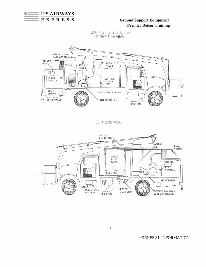
GENERAL INFORMATION
Ground Support Equipment Premier Deicer Training
1
GENERAL INFORMATION

Ground Support Equipment Premier Deicer Training
DESCRIPTION
This chapter outlines the physical and functional description of the Premier “Express Heat” Deicer. A complete description of the unit and its features are included. The Premier Engineering & Manufacturing, Inc., “Express Heat” series aircraft deicer is a truck mounted unit featuring a high capacity single pass fluid heating system. The “Express Heat” system results in a deicer that is simple to operate and extremely easy to maintain. The “Express Heat” system requires only 90 seconds of preheat time prior to full operation.
Throughout this manual reference to “deicing” and “antiicing” will be made for the purpose of describing a component and/or system. The term “deicing” will refer to the deicing fluid system and “antiicing” will refer to the agent or system to be used for the antiicing process. The purpose for this distinction is due to the ever changing fluids utilized in antiicing process.
DEMENSIONS
Overall Length 302”Overall Width 94”Overall Height (Stowed Position) 160”Working Height (Platform + 5 Feet) 450”Dry Weight 21,300 lbs
CHASSIS
Please refer to the applicable chassis manual for further information. The applicable chassis comes equipped with standard information with exception of the Premier extended view cap.
MAIN CABINET
Premier has implemented the exclusive “Easy Access” design that provides the most convenient and efficient admission available to the industry. The cabinet is constructed of combination carbon steel and stainless steel tubing, with an outer skin of 16 gauge galvanized steel to insure years of rust free service. Four large access removable doors and 2 large removable access panels provide “Easy Access” to all of the components housed within. The main frame is attached to the chassis utilizing a 5/8” grade 8 Ubolt assembly located at 4 points on the frame as well as a bolt through mount located at the front of the cabinet. Fluid storage tank access ports are located on the top drivers side of the vehicle and can be accessed utilizing the ladder located on the back of the cabinet.
2
Ground Support Equipment Premier Deicer Training
GENERAL INFORMATION
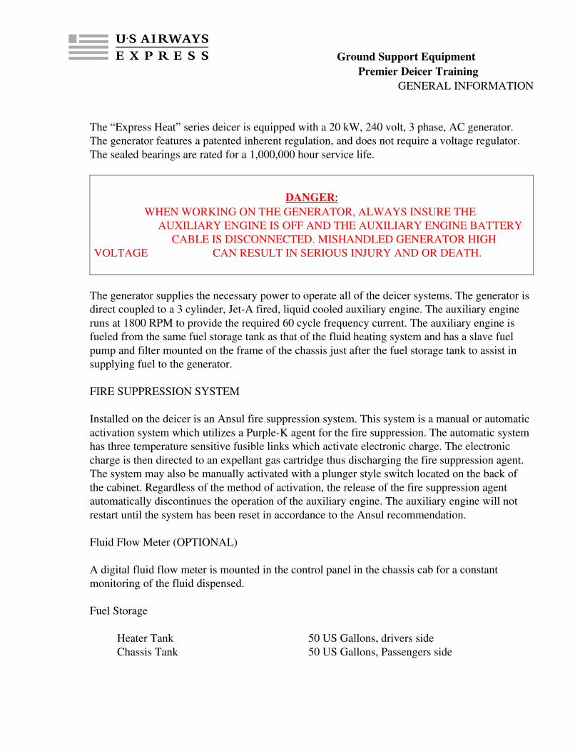
The “Express Heat” series deicer is equipped with a 20 kW, 240 volt, 3 phase, AC generator. The generator features a patented inherent regulation, and does not require a voltage regulator. The sealed bearings are rated for a 1,000,000 hour service life.
DANGER : WHEN WORKING ON THE GENERATOR, ALWAYS INSURE THE
AUXILIARY ENGINE IS OFF AND THE AUXILIARY ENGINE BATTERY CABLE IS DISCONNECTED. MISHANDLED GENERATOR HIGH
VOLTAGE CAN RESULT IN SERIOUS INJURY AND OR DEATH.
The generator supplies the necessary power to operate all of the deicer systems. The generator is direct coupled to a 3 cylinder, JetA fired, liquid cooled auxiliary engine. The auxiliary engine runs at 1800 RPM to provide the required 60 cycle frequency current. The auxiliary engine is fueled from the same fuel storage tank as that of the fluid heating system and has a slave fuel pump and filter mounted on the frame of the chassis just after the fuel storage tank to assist in supplying fuel to the generator.
FIRE SUPPRESSION SYSTEM
Installed on the deicer is an Ansul fire suppression system. This system is a manual or automatic activation system which utilizes a PurpleK agent for the fire suppression. The automatic system has three temperature sensitive fusible links which activate electronic charge. The electronic charge is then directed to an expellant gas cartridge thus discharging the fire suppression agent. The system may also be manually activated with a plunger style switch located on the back of the cabinet. Regardless of the method of activation, the release of the fire suppression agent automatically discontinues the operation of the auxiliary engine. The auxiliary engine will not restart until the system has been reset in accordance to the Ansul recommendation.
Fluid Flow Meter (OPTIONAL)
A digital fluid flow meter is mounted in the control panel in the chassis cab for a constant monitoring of the fluid dispensed.
Fuel Storage
Heater Tank 50 US Gallons, drivers sideChassis Tank 50 US Gallons, Passengers side
Ground Support Equipment Premier Deicer Training
3
AERIAL LIFT
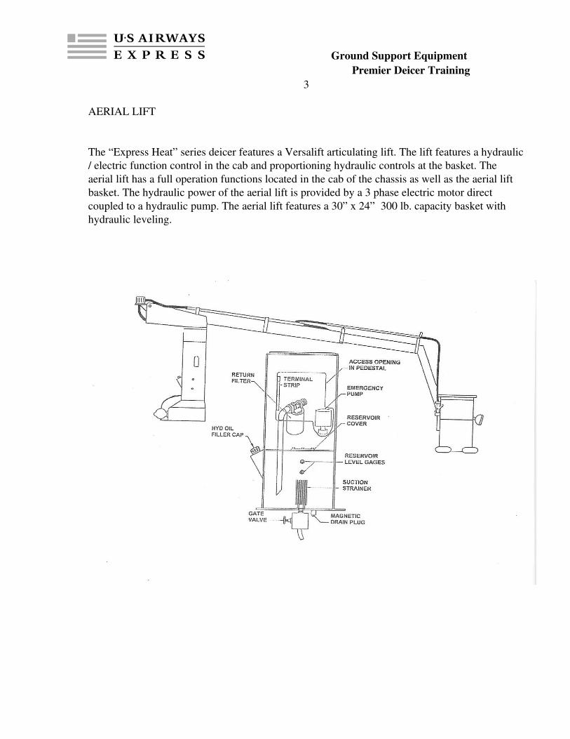
The “Express Heat” series deicer features a Versalift articulating lift. The lift features a hydraulic / electric function control in the cab and proportioning hydraulic controls at the basket. The aerial lift has a full operation functions located in the cab of the chassis as well as the aerial lift basket. The hydraulic power of the aerial lift is provided by a 3 phase electric motor direct coupled to a hydraulic pump. The aerial lift features a 30” x 24” 300 lb. capacity basket with hydraulic leveling.

Ground Support Equipment Premier Deicer Training
4
HYDRAULIC SCHEMATIC

Ground Support Equipment Premier Deicer Training
5
DEICE FLUID SYSTEM
FLUID STORAGE TANK
The “Express Heat” deicer series offers a 750 to 2000 gallon capacity, polypropylene fluid storage tank, with optional tank configuration for deicing / antiicing combination. The tank is manufactured using compression molded, stress relieved, virgin polypropylene. A 10” fill port is located on the drivers side of the tank and can be removed to access the tank through a 22” square opening. All of the plumbing is attached to the tank utilizing poly bulkhead fittings. Although the tank is constructed of polypropylene, it is capable of storing fluid up to 110 degrees F. The fluid level gauge is a sight style located on the drivers side of deicer cabinet. The sight gauge is simply a slot in the cabinet which you look through to see the level in the tank. For night time use, the fluid tank is illuminated for clear visibility of the fluid level.
FLUID DELIVERY SYSTEM
The fluid delivery system on the “Express Heat” deicer consists of a high speed, high temperature, internally regulated 7 stage centrifugal pump driven by a 7 ½ hp, 240 volt, 3 phase, electric motor. The electric motor rotates at 3450 RPM and is direct coupled to the fluid delivery pump. There is a low fluid shut down switch located adjacent to the antiicing fluid storage tank. The low fluid shut down switch discontinues the operation of the fluid pump when the level of the fluid drops below the 50 gallon level. This will prevent the pump from inadvertently being run dry causing permanent damage to the pump. The fluid delivery system takes fluid from the tank, through the fluid pump, diverts the fluid in equal amounts and in a parallel configuration through the three heaters and out of the dispensing guns. If the fluid delivery guns are not in the open position, the fluid pump does not circulate fluid through the heating system and simply cavitates within the fluid pump.
NOTE: Extended periods of cavitation will cause serious damage to the fluid delivery pump. The fluid pump should not be allowed to operate in the cavitation mode for longer than 5 minutes.
A ¼” fluid line is needed to return a small portion of the fluid in the pump back to the fluid storage tank for reasons of cooling the fluid pump during extended cavitation. Also, in the fluid delivery system, down stream from the fluid heaters is a “Cold Fluid Purge” valve. This valve is used to circulate cold fluid through the fluid heaters in the start up procedure. The cold fluid purge process should take approximately 90 seconds. On the exit port of the cold fluid purge valve is a constrictive port. The port is used to regulate the fluid flow through the cold fluid purge valve during the purging process. Because the fluid delivery pump will produce a high fluid flow rate at a lower pressure, this constrictive port serves to reduce the flow of the fluid through the heaters during the purging process. Fluid directed to the aerial lift dispensing gun is
Ground Support Equipment Premier Deicer Training
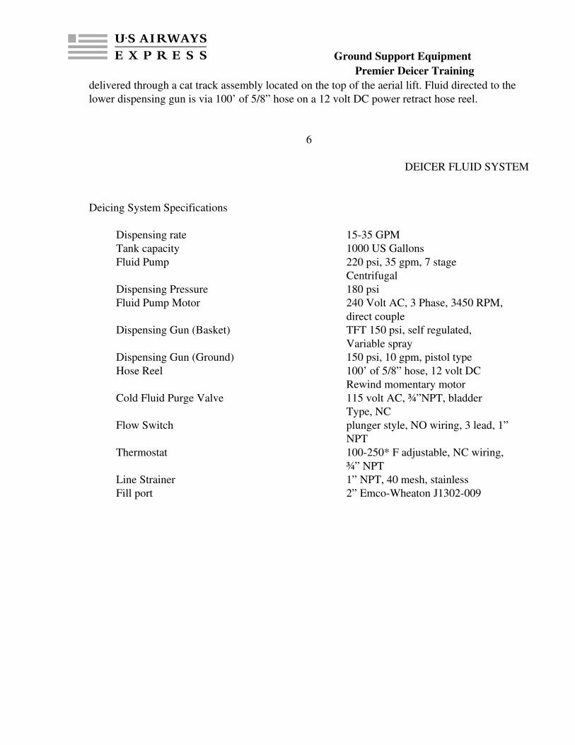
delivered through a cat track assembly located on the top of the aerial lift. Fluid directed to the lower dispensing gun is via 100’ of 5/8” hose on a 12 volt DC power retract hose reel.
6
DEICER FLUID SYSTEM
Deicing System Specifications
Dispensing rate 1535 GPMTank capacity 1000 US GallonsFluid Pump 220 psi, 35 gpm, 7 stage
CentrifugalDispensing Pressure 180 psiFluid Pump Motor 240 Volt AC, 3 Phase, 3450 RPM,
direct coupleDispensing Gun (Basket) TFT 150 psi, self regulated,
Variable sprayDispensing Gun (Ground) 150 psi, 10 gpm, pistol typeHose Reel 100’ of 5/8” hose, 12 volt DC
Rewind momentary motorCold Fluid Purge Valve 115 volt AC, ¾”NPT, bladder
Type, NCFlow Switch plunger style, NO wiring, 3 lead, 1”
NPTThermostat 100250* F adjustable, NC wiring,
¾” NPTLine Strainer 1” NPT, 40 mesh, stainlessFill port 2” EmcoWheaton J1302009

Ground Support Equipment Premier Deicer Training
7

Ground Support Equipment Premier Deicer Training
8

Ground Support Equipment Premier Deicer Training
ANTIICING SYSTEM
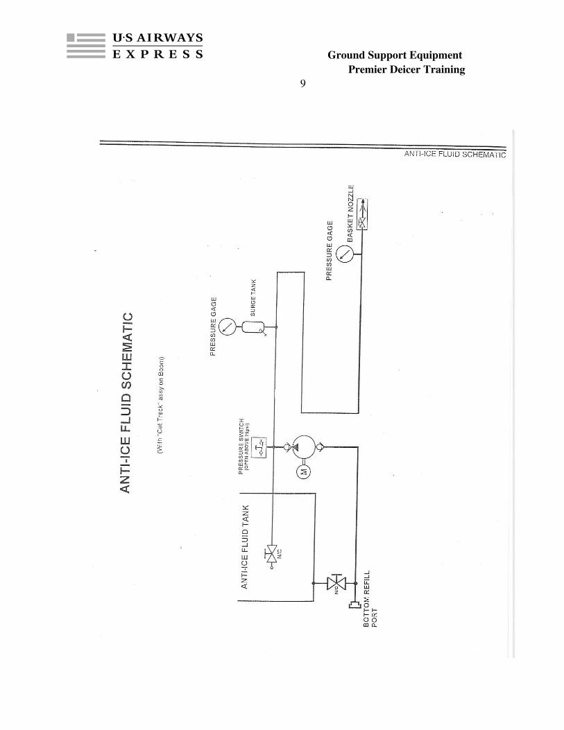
The Premier Antiicing System option includes a tank configuration of customers choice, a Hardi diaphragm style pump driven by a 3 hp, 230 volt 3 ph, 1100 rpm motor. A speed control is used to vary fluid pump pressures. The speed control breaks down the frequency of the power going into the antiicing motor thus varying the speed, an additional aerial lift Cat Track assembly, an antiicing delivery gun located at the basket of the aerial lift, and a selector switch located at the basket of the aerial lift for selection of fluid to be dispensed. Antiicing fluid cannot be dispensed from the ground. When the selector switch is in the Type I position, the antiicing fluid pump is not in operation. When the selector switch is in the Type II position, the deicing fluid pump is not operational, i.e. both deicing and antiicing fluid cannot be dispensed simultaneously. The antiicing system is operated on a pressure sensitive switch located adjacent to the antiicing pump. As the antiicing dispensing gun is closed, the pressure in the system, approximately 50 PSI, activates the pressure switch and discontinues the power to the antiicing pump motor. The antiicing tank is located aft of the deicing tank and the level of the fluid is measured by a sight gauge located on the drivers side of truck. Filling of the antiicing fluid tank can be accomplished by using the antiicing pump and a small series of adjustments to the valving. For additional information on the suction filling of the antiicing fluid, refer to the Type II (Antiicing) Plumbing Schematic.
AntiIcing System Specifications
Dispensing rate 522 GPMTank capacity 200 US GallonsOperating pressure 50 PSIFluid Pump 3 Diaphragm Hardi, 22 gpm @ 540 rpm
11/4” inlet, 1” outlet, Morse#4 shaft w/ set screw
Pump Motor 230 volt AC 3 Phase, 3 hp, 1 1/8”Shaft w/key
Pressure Switch ½” NPT, NC wiringSurge Tank ½” NPT, 1.5 quart, 500 psi maxSpeed Master Control 220 volt AC 3 Phase, LED display,
060 cycle adjustable, 3 hp ratingDelivery Gun TFT 50 psi, Type II, variable sprayFill Port 2” Civicon OPW 1663AN
Ground Support Equipment Premier Deicer Training
9

Ground Support Equipment Premier Deicer Training
10
FLUID HEATING SYSTEM
FLUID HEATERS
The fluid heating system features 3 single pass coil heat exchangers aligned in parallel. The burners, which are ignited by JETA/ DIESEL , via a two pipe system and are located on top of the coil assembly and propel the flame downward and then back upward, toward the exhaust port. The heat exchanger coil is wrapped in one layer of 16 gauge galvanneal and insulated with ½” high density refractory fiber. A second outer layer of 18 gauge 304 stainless steel completes the coil shrouding. There is an 80 sq. in. exhaust port located at the top front side of the heater coil assembly. The fluid to be heated enters the heater coil, passes through approximately 190’ of tubing and then exits the heater coil. Located on each heater assembly is a fluid flow switch and a fluid thermostat. The fluid flow switch and the fluid thermostat are wired in a series with the burner primary control. The burner primary control activates and deactivates the burner fuel solenoid. Simply stated, the operation of the heater consists of the following;
1. The Heater ON/OFF switch is put in the “ON” positionThis energizes the burner blower motor. The blower motor, via a thermo couple, rotates the burner fuel pump. Additionally, the blower motor rotates the “squirrel cage” providing the combustion air to the burner. Simultaneously, the burner transformer is energized and excites the electrodes located in the burner chamber.
2. The “Honeywell Primary Control” awaits the signal from the fluid flow switch and the fluid thermostat switch. When either the fluid dispensing gun and/or the “Cold Fluid Purge” valve is opened, fluid will begin to pass through the burner coils. At this time, the fluid flow switch will sense the flow and send a electronic current to the fluid thermostat. Provided the fluid flowing through the coils is not greater then the setting on the fluid thermostat, the electronic current will be sent back to the “Honeywell Primary Control” completing the circuit. Completing this series circuit activates the “Honeywell Primary Control”.
3. The Fuel Solenoid receives the electronic current to activate the “Honeywell Primary Control”. When the fuel solenoid opens, fuel is allowed to enter the burner chamber, passing through the burner nozzles at approximately 130150 PSI. Utilizing the spark made by the excited electrodes, the atomized fuel begins to burn until either the fluid flow stops or the fluid flowing through the burner coil reaches the preset temperature noted on the fluid flow thermostat.
Burner Specifications
Heaters 3 – 1.4 Million BTU Jet – A Fired Heater Coil 189’ of ¾”black iron pipe

Ground Support Equipment Premier Deicer Training
11
FLUID HEATING SYSTEM
Heater Plumbing parallelBlower Motor 220 Volt AC, 3450 RPM, ½” shaft Fuel Pump 130150 PSI, ½” shaft, two pipe
ConfigurationFuel Solenoid 115 Volt AC, normally closed, 1/8”
NPTNozzles 3.5 GPM, 80’ solid patternElectrodes 1/8” – 3/16” gap setting, ¼”from
Flame LockTransformer 12014,000 Volts step up, .23 mACad Cell Cadmium Cell, .255 mA resistancePrimary Control 115 volt AC, 14 volt AC circuit, 15
Second delay.

Ground Support Equipment Premier Deicer Training
12
BURNER ASSEMBLY

Ground Support Equipment Premier Deicer Training
12aELECTRICAL SYSTEM

Ground Support Equipment Premier Deicer Training
ELECTRICAL SYSTEM
The electrical system is a combination of 12 volt DC current and 240 volt, 3 phase, AC voltage. Where possible, the wiring is marked with exterior wire markings indicating the service of the wire, voltage of the wire, size of the wire and the style of wire. Most applications permit the use of oil resistant, water resistant S/O cord.
All AC voltage is directed from the generator to a load center located in the back of the deicer cabinet. There is not a main circuit breaker for the power input source, however , each individual circuit is terminated through its own respective breaker. Additionally, all of the wiring from the load center to the interior control panel is 115 volt AC. All of the 240 voltage is direct to the components via a magnetic contactor that has a 115 volt activation. All of the magnetic contactors are located in the load center.
ELECTRICAL SYSTEM SPECIFICATIONS
Generator 20 KW, 3 Phase, 240 Volt AC12 lead, internally regulated
Load Center 3 Phase, 240 Volt AC, 4 Lead,125 amp
Primary Power 115 Volt AC, 1 Phase Wiring S/O Cord when applicable,
Copper multi strandLabel Markers Brady 517 wrap around
The output voltage of the Generator can be checked using a multimeter. It can be checked at the load center and should be as follows:
***WARNING***When working on the electrical system, insure the Auxiliary engine is not running
and the chassis Battery cable is disconnected. Serious injury or death can result from high voltage electrocution.
Ground Support Equipment Premier Deicer Training
L1 to L0 125 voltsL2 to L0 125 voltsL3 to L0 220 volts
13
ELECTRICAL SYSTEM
CONTROL PANEL
The deicer function controls are located in the chassis cab of the deicing unit. All deicer components are equipped with a rocker style illuminated switch. When the switch is in the “OFF” position, the rocker switch will be in the nonilluminated position. Conversely, when the rocker is in the “ON” position, the rocker switch will be illuminated. All heater switches are accompanied by an ignition light located directly above the corresponding rocker switch and indicates the burner operation of the burner. In addition to the components function switches, the control panel is equipped with an auxiliary engine ignition switch, auxiliary engine preheat indicator, auxiliary engine low oil, over temperature, and charging system warning light and “Tattle Tail” override. Also included on the control panel is a fluid temperature gauge. The control panel is mounted via a pedestal to the floor of the chassis cab. All the wires and capillaries are run through the back of the cab, along the cab floor, and through the pedestal mount. Finally, the center of the control panel.
COMMUNICATIONS SYSTEM
The installed Communication System allows the individual in the aerial lift to remain in contact with the individual in the chassis cab. A David Clark communications system, which is voice activated, is installed utilizing a chassis cab master station, and an aerial lift basket mount remote station. The two stations are interconnected via a 22/3 shielded wire through the inner portion of aerial lift. The master station is powered by 12 volt DC from the chassis fuse panel. The ground level station is equipped with a single ear headset, and the basket is equipped with a dual ear headset. Both stations have volume control for their respective headset, and the master station has a system control for volume. Each headset is also equipped with a on/off button.
CHASSIS SPEED CONTROL
Incorporated into the chassis engine and the aerial is a speed limiter. This control limits the speed of the chassis to 4 MPH (5.87 FT/SEC) while the aerial lift is out of the stowed position. Activating the speed control is a proximity switch located at the tower support saddle. The actual speed control works with a potentiometer in the accelerator supplying power to the 12 volt motor located in the speed control box. This 12 volt motor receives impulses from the
Ground Support Equipment Premier Deicer Training
speedometer so that the chassis engine will generate the power needed to achieve the 4 MPH. When the lift is in the stowed position, the chassis operates with full function.
14
CONTROL PANEL

Ground Support Equipment Premier Deicer Training
14a
ELECTRICAL SCHEMATIC

Ground Support Equipment Premier Deicer Training
15
LOAD CENTER

Ground Support Equipment Premier Deicer Training
15a
ELECTRICAL SCHEMATIC

Ground Support Equipment Premier Deicer Training
16
TROUBLESHOOTING PROCEDURES
Ground Support Equipment Premier Deicer Training
TROUBLESHOOTING
The following troubleshooting guide assumes you understand how to operate the Premier “Express Heat” Deicer.
A. Fluid Heaters
The following information is presented for the purpose of troubleshooting individual components. When possible, exclusivity to the component described is attempted, however, it may be necessary to adjust or evaluate additional components for completion of the evaluation.
Any individual heater does not operate, there is fuel in the tank, there is fluid in the Deice fluid tank, and there is pressure in the Deice fluid system.
1. Heater switch is “ON” but burner does not operate.
A. Try another switch to insure the generator is providing power.
B. Check to see if the rocker switch is illuminated.
1. If switch is not illuminated, reset breakers in load center.
C. Check to see if blower motor is spinning.
1. If blower motor is not spinning, reset thermal protection on blower.
2. If after resetting thermal, blower does not come on or trips the thermal again, check to see if fuel pump or motor is bound.
3. If fuel pump spins freely, replace blower motor.
D. Check ignition.
1. Open transformer, and with the power on, cross posts with screwdriver.
2. Remove Gun assembly and regap electrodes to 1/8”3/16” with power off.
3. Close transformer slowly and look for stray spark, with power on.
17

Ground Support Equipment Premier Deicer Training
TROUBLESHOOTING PROCEDURES
E. Check fuel supply.
1. With blower motor on, open fuel pump bleed valve.2. If no fuel is present, check 12 volt auxiliary fuel pump operation.3. Check fuel lines for ice or blockage.4. Replace fuel filter cartridge.
F. Check system setting.
1. Using a jumper wire, cross the “T” terminals on the Primary Control.2. If burner ignites, check flow switch and thermostat.3. If burner does not ignite.
a. Check operation of fuel solenoid.b. Check operation of Primary Control.c. Replace Cad Cell.
B. Deicing Fluid Pump
The following information is presented for the purposes of troubleshooting individual components. When possible, exclusivity to the component described is attempted, however, it may be necessary to adjust or evaluate additional components for completion of the evaluation.
The deicing fluid tank is full of fluid but the fluid pump will not operate.
1. Fluid pump is on but system will not generate pressure.
A. Insure there is power to the fluid pump.
1. Check rocker switch for illumination.2. If switch is not illuminated, reset relay breaker in load center.3. Try another switch to see if there is AC power.
B. Insure there is fluid getting to the fluid pump.
1. Open and close the ball valve located in the bottom load compartment.2. Remove the ¼” fluid line from the fluid pump manifold with pump
“OFF”.

Ground Support Equipment Premier Deicer Training
18
TROUBLESHOOTING PROCEDURES
C. Check and clean fluid pump line strainer.
D. Insure the “Roll Over Valve” is not in the open position.
E. Insure Type II selector switch in the basket is in Type I position.
F. Insure magnetic contactor in load center is being activated.
1. Manually depress contactor and watch pump.2. Check low fluid shut down switch.
G. Check antiicing system magnetic contactor to see if it activated.
H. Visually inspect fluid pump for operation.
1. Listen for generator load when switch is turned on.2. Feel for air flow at vented end of fluid pump.
I. Insure the pump is not air locked.
1. With pump in the OFF position, remove the ¼” fluid line on manifold. Put breaker in the “OFF” position at the load center and turn the fluid pump switch to the “ON” position. Carefully switch the relay breaker to the “ON” position and be prepared to shut it off immediately.
C. Deicing Fluid System
The following information is presented for the purposes of troubleshooting individual components. When possible, exclusivity to the component described is attempted, however, it may be necessary to adjust to evaluate additional components for completion of the evaluation.
With any heater problems, it is highly recommended that you check heaters in accordance with the “Heater Troubleshooting” guide prior to any component replacement.
Fluid pump, heaters and aerial lift are “ON”, but heaters are not operating properly.
1. The heater ignition lights come on as soon as the heater switches are turned on and without any guns in the open position.

Ground Support Equipment Premier Deicer Training
19
TROUBLESHOOTING PROCEDURES
A. Check cold fluid purge valve operation.
1. Visually look in top of tank to see if there is a large amount of fluid passing back to the tank. This should be done with the heaters in the “OFF” position.
B. Close cold fluid purge ball valve and turn heaters on.
1. If system stops circulating with ball valve closed, reopen ball valve and inspect for flow again. If flow persists, remove the coil from the top of the cold fluid purge valve and rerun test. If flow persists, change cold fluid purge valve.
Check for leak in system ( dumping fluid on the ground ).
2. The heater ignition light comes on as soon as the heater switch is turned on and ` without the fluid pump on.
A. Check the heater flow switch for debris making it stick in the open position.
1. Close fluid system ball valve and remove top of flow switch, slide switch mechanism up and down until it moves freely. Clean any debris from the switch. Reinstall flow switch and turn burner on. If system still comes on, remove Primary Control, install new.
3. The heater ignition light does not come on, but the heater is igniting.
A. Determine which heater or heaters are igniting.
1. Turn heater off and inspect fuel solenoid, replace if faulty.
4. The heater comes on normally, but during cold fluid purge, the Honeywell primary control trips reset.
A. Reset Primary Control and turn only the heater that tripped the reset on.

Ground Support Equipment Premier Deicer Training
B. Run system through cold fluid purge again and see if burner is igniting. If burner is igniting but tripping Primary Control.
1. Clean cad cell lens.2. Regap the electrodes on the heater gun assembly.
20
Troubleshooting Procedures
5. The heater pops the Primary Control during cold fluid purge and with the fluid gun open.
A. Inspect heater in accordance with “Heater troubleshooting” guide.
B. Inspect exhaust smoke for coloration.
1. If exhaust is dark, air bands must be opened.
2. If exhaust is white, air bands are open to far.
3. If heater rumbles, adjust air bands to eliminate the rumble.
6. All the heaters come on during cold fluid purge but trip the Primary Controls.
A. Insure there is fuel in the tank and at the heaters.
B. Follow instructions in the “Heater troubleshooting” guide.
7. Fluid pump has pressure, but heaters will not come on.
A. Open fluid dispensing gun into tank.
1. If heaters come on, check operation of cold fluid purge valve.
8. Heaters do not come on with cold fluid purge or with gun open.

Ground Support Equipment Premier Deicer Training
A. Check fluid pump operation.
B. Check Honeywell Primary Control resets.
C. Follow instructions in the “Heater troubleshooting” guide.
21
Troubleshooting Procedures
D. AntiIcing Fluid System
The following information is presented for the purposes of troubleshooting individual components. When possible, exclusivity to the component described is attempted, however, it may be necessary to adjust or evaluate additional components for completion of the evaluation.
1. There is no pressure in the ANTIICE system.
A. Insure that there is power going to the antiicing fluid pump.
1. Check fluid pump switch for illumination.2. Check fluid pump breaker and reset.3. Check relay breaker and reset.
B. Insure the AntiIcing selector switch is in the “Type II” position.
C. Insure that the ball valve going to the antiicing pump is opened.
D. Insure the ball valve returning fluid to the antiicing tank is closed.
E. Check for pressure in the deicing system.
1. If there is pressure in the deicing system, check the operation of the KUP 11A5512V relay in the load center for the AntiIcing switching.
F. Check AntiIcing pump magnetic contactor. Magnetic contactor should be activated. You may manually depress the contactor for test purposes.
G. Check message on screen of speed control.

Ground Support Equipment Premier Deicer Training
1. If message on screen indicates “RUN” then motor should be getting power.
2. If message on screen indicates “Fault” or “Overload” turn breaker for fluid pump off for a period of 1 minute and then reset.
H. Check AntiIcing System pressure switch.
1. Using a jumper wire, cross the C and NC posts in the switch.
22
Troubleshooting Procedures
I. Check motor for any discoloration or overheating smell caused by burned winding.
J. Insure the belt is tight and on the pump and motor.
K. See if the motor is spinning at all.
1. If motor is not spinning and power is at the motor, replace motor.
L. Insure that the fluid flow to and from the pump is not blocked.
1. Disconnect hose going to the suction of the pump is not blocked.2. Check hoses leading through the lift to the trombone for kinks or
blockage.
M. Inspect pump for leaks or damage.
N. Turn pump by hand testing for restrictions in the rotation.
O. Check to see if pump appears to be starting and stopping with a high frequency, i.e. on/off, on/off, on/off, etc. when the gun is open.
1. If so, close both ball valves and drain surge tank.2. Check setting on the Pressure Switch. Pressure setting should be 75 psi on
control inside pressure switch cover.
2. System comes up to pressure and then stops pumping when gun is open.

Ground Support Equipment Premier Deicer Training
A. Check power input to AntiIcing system motor.
1. Test and reset fluid pump breaker.2. Check message on the antiicing motor screen. If message reads “Fault”
turn fluid pump breaker off for 1 minute message comes up again, turn system off and contact manufacture.
3. Speed Control will not indicate “RUN” ( MOST Deicers HAVE BEEN CHANGED so this procedure may be obsolete )
A. With power on; perform the following functions;
1. Depress “Program Key” on Speed Control Key Pad.2. Press “UP” arrow until screen reaches “0019”. Press “Enter”.
23
Troubleshooting Procedures
3. Press “Down” arrow until you reach “Control”. Press “Enter”. Press “Up” arrow until you reach “Remote”. Press “Enter”.
4. Press “Down” arrow until you reach “Stop”. Press “Enter”. Press “Up” arrow to “Ramp”. Press “Enter”.
5. Press “Down” arrow until you reach “Start”. Press “Enter”. Press “Up” arrow to “Power Up”. Press “Enter”
6. Press “Down” arrow until you reach “FX Boost”. Press “Enter”. Press “Up” arrow until you reach “6.0”. Press “Enter”.
7. Press “Down” arrow until you reach “Decel”. Press “Enter”. Press “Down” arrow until you reach “5.0 Sec”. Press “Enter”.
8. Press “Down” arrow until you reach “Accel”. Press “Enter”. Press “Down” arrow until you reach “5.0 Sec”. Press “Enter”.
9. Press Prog/Run button on key pad. It will now be necessary for you to shut the power off the speed control. This can be done by either shutting off the “Fluid Pumps” breaker or by shutting down the generator. The power should be shut down for a period of 1 minute or until the LED display goes blank.

Ground Support Equipment Premier Deicer Training
24

Ground Support Equipment Premier Deicer Training
25

Ground Support Equipment Premier Deicer Training

Ground Support Equipment Premier Deicer Training