ground software maintenance facility …...41849-g159-026 ground software maintenance facility...
TRANSCRIPT

41849-G159-026
GROUND SOFTWAREMAINTENANCE FACILITY(GSMF) USER'S MANUAL
FINAL - APPENDICES
26 FEBRUARY 1986(NASA-CB-178806) G B O U N D SGFl:i£BEHAIBIEBAHCE FACILITY. (GSHF) OSES* S M A N U A L .APPENDICES NASA-CB-178806 HAS; 1,26: 178806iEPT-41849-Gl59r-G26-APP fiC AG5/BF A01 Final UnclasEeport JTEH Defense aad Space Systems Group) 63/61 42925
TRW DEFENSE SYSTEMS GROUPHUNTSVILLE OPERATIONS213WYNN DRIVEHUNTSVILLE, ALABAMA 35805
https://ntrs.nasa.gov/search.jsp?R=19860015673 2020-04-17T07:01:01+00:00Z

rttV
|em Development Division 213 Wynn DriveJ~se Systems Group Huntsviiie. Alabama 35305
205-837-2400
SN41849.0006002.VOB.86-606828 February 1986
McDonnell Douglas Astronautics Co.Huntsville DivisionP.O. Box 1181Huntsville, Alabama 35807
ATTENTION: MR. W. R. LOKKEN
SUBJECT: SUBCONTRACT 83916018, GSMF DELIVERABLES,
Dear Mr. Lokken,
Per Supplemental Agreement 04, paragraph 4.2 of the June1984 revised Statement of Work, enclosed are the followingfinal reports and baselined software:
Detailed Design Document (Final)Users Manual (Final)System Manual (Final)GSMF Baselined SoftwareAcceptance Review Demonstration Package
If you should have any questions, please contact Mr. GarryGriffith at MSFC, Building 4708/B26A or telephone (205)453-3910.
TRW Inc. , ; •Defense Systems Group (V
V. O'L. BainContracts ManagerSystem Development Division
End: As Stated
cc: V. 0. Bain M. E. Hollowich TRW File (2)N. L. Blanks G. M. Lide V. A. WulffF. P. Herring G. C. Hitt
Delivery Package Received by:
W. R. Lokken, Branch Chief DateSoftware and Ground Computer SystemsMDAC-HSVTRW Inc.

41849-G159-026
GROUND SOFTWAREMAINTENANCE FACILITY(GSMF) USER'S MANUAL
FINAL • APPENDICES
26 FEBRUARY 1986
PREPARED BY:
V. Aquila '/D. DerrigG.Griffith
APPROVED BY:
M. E. HollowichProject Manager
J. Elrby, GSMFReview Authority
TRW DEFENSE SYSTEMS GROUPHUNTSVILLE OPERATIONS213WYNN DRIVEHUNTSVILLE, ALABAMA 35805

CONTENTS
APPENDIX A GSMF OPERATING PROCEDURES
APPENDIX B ACRONYMS AND TERMINOLOGY
APPENDIX C SWID RELATION FORM GENERATION PROCEDURE
APPENDIX D STIMULI/MEASUREMENT SWID PAIRS GENERATION
APPENDIX E PCU OPERATING SYSTEM SERVICES
APPENDIX F GSMF DATA BASE GENERATION
APPENDIX G MITRA SETUP MODE DATA
APPENDIX H MITRA OPERATING PROCEDURES
Page
A-l
B-l
C-l
D-l
E-l
F-l
G-l
H-l
11

ILLUSTRATIONS
C-l Subtables and Subparts C-2
D-l ATE SWID Report (Stimuli) D-2
D-2 ATE SWID Report (Measurement) D-4
D-3 SWID Relations Form . D-6
E-l Test Console Keyboard . E-3E-2 Display Generation Overview E-9
E-3 FUNCTION Key Parameter List E-20
E-4 COMPOSE Field Entry Parameter List E-22
E-5 Display Control Request Block E-26
E-6 Display Control Request Block E-31
F-l Setup Mode VM/CMS Procedures F-2
F-2 SWID Relations WCMS Procedure F-5
F-3 SWID Pairs VM/CMS Procedures F-6
F-4 SMID Data File Listing F-7
F-5 SMID Data File VM/CMS Procedures F-8
F-6 Run Documentation VM/CMS Procedures F-9
F-7 SWID Initial Data Listing F-10
F-8 SWID Initial Data VM/CMS Procedures F-12
F-9 GSMF Data Base Generation VM/CMS Procedure F-13
G-l ATE Fetch Command Generation VM/CMS Procedure G-2
G-2 MITRA Fetch Command Tape Load Procedure G-3
G-3 DGNC MITRA Tape Load Procedure G-4
iii

TABLES
Page
E-l Display Compose Field Sub-parameter Validation E-23
E-2 Display Compose Field Parameter Conversions E-24
E-3 Display Service Request Block Cross-Reference E-27E-4 Program MFUPDATE and Procedure ^UP Card Image Input
File Example E-33
iv

PREFACE
The GSMF User's Manual consists of a "Final" and "Final-Appendices".
These two volunes are bound separately for the convenience of the reader.

APPENDIX A
GSMF POWER-UP SEQUENCES

APPENDIX A
GSMF OPERATING PROCEDURES
The following is a list of operating procedures that shall be used to:
1) Start the GSMF 3250
2) Back up the system
3) Shut down the GSMF 3250 system
4) Save disk to tape
5) Perform a disk check and close any open files
6) Perform selective disk-to-tape
7) Initialize disk pack
8) Dump tape to printer.
A list of CSS Procedures is presented on page A-6 that will allow the user to
assemble tasks, link, compile, backup the system, generate/establishment/printdisplay pages, cancel tasks in memory, and to TET an assembly task without
having to enter the .CSS commands every time. Examples are given forestablishing, generating, and printing display pages (A-6, A-7).
A-l

PROCEDURE FOR STARTING THE GSMF 3250
SIGN THE UTILIZATION LOG BOOK
1. If the GSMF 'RELEASE1 disk is not in the drive and "READY".
1A. If the "RELEASE" disk is loaded.A. Press the button under "START".B. The drive will spin up and the "READY" light come on.
IB. IB. If another disk is loaded.A. If the "READY" light is on, mark the disk off (MA MSM:, OFF)
press the button under "START". The disk will spin down andthe "READY" light will go out.
B. Be sure the "READY" light is out.C. Open the door on the top of the disk drive.D. Place the upper dust cover for thte disk presently mounted over
the disk.E. Turn the handle counter-clockwise until it clicks.F. Remove the disk and dust cover assembly.G. Place the lower dust cover on the disk.H. Store the disk on a shelf in the disk rack.
1C. If no disk is loaded:A. Open the door on the top of the disk drive.B. Remove the lower dust cover by soueezing the lock on the lower
cover.C. Place the disk with the upper dust cover still on over the
spindle.D. Turn the handle clockwise until it locks firmly.E. Lift off the upper dust cover.F. Place the upper cover neatly over the lower cover and store it
on the back of the drive enclosure.G. Press the button under "START".H. The drive will spin up and the "READY" light come on.
2. Move the key to "ON".
3. Move the IPL switch to "ENABLE".
4. Momentarily press the "INIT" switch. A list of devices will appear onthe system console if you have made it so far. If not, try again or gethelp.
5. Move the IPL switch to "DISABLE".
6. Move the key to 'LOCK1 .
7. Enter "DS67" at the prompt for device.
8. Enter 'GSMF3250.0S" at the prompt for file.
A-2

9. Memory test will run. Wait for it to end.
10. Enter time and date when prompted as 'SET TIME W/DDAY,HH:MM:SS"
11. Enter 'SCONTINUE'
12. BACKUP PROCEDURES - First IPL of the day only!!!!!!!
MAKE SURE THE 'PE/NRZI ' LIGHT IS LIT ON THE TAPE DRIVE
The printer must be ready and a tape loaded for the backup to run. Ifproblems persist with one or the other, restart the backup to preclude'HIDDEN" problems.
12A. Monday - Thursday backup procedure:
A. Mount the daily tape for the proper day of the week.
Mount the reel and thread the tape as indicated on the tape drive.
Wind 3 or 4 turns on the lower reel.
Press "LOAD". The 'ONLINE1 and "LOAD" lights will come on. If not, tryagain or get help
B. "DAILY" wait until backup finishes.C. Dismount and store the tape.
Press "RESET" then "REWIND". Holding "REWIND" will wind the "entiretape back on the upper reel.
D. Put the listing in the book marked "DAILY".
12B. Friday backup:
A. Check the log sheet to see if a Friday or total backup is due thisdate.
If Friday:
Load the proper Friday tape as indicated on the log sheet.
"DAILY" wait until backup finishes.
Dismount and store the tape.
Put the listing in the book marked "FRIDAY".
If total:
Load the first reel of the proper total tape as indicated on the logsheet.
A-3
"TOTAL" wait until backup finishes. This will require mountingseveral reels as prompted by the procedure.
Di smount and store the tapes.
Put the listing in the book marked "TOTAL".
B. A-F-T-E-R the backup is run reset the "DAILY" procedure:'EDIT1
'6 DAILY.CSS"Change the date following the keyword "SINCE" to the Friday date onLine 11 of the CSS.
13. "UP"
PROCEDURE FOR SHUTTING THE GSMF 3250 DOWN
1. Get everyone clear and signed off.
2. "CLEANUP"
3. 'MA MSM:, OFF"
4. "D D" - Verify that the devices are off line.
5. Press the "START" button on the disk drive. The "READY" light will goout.
SIGN THE UTILIZATION LOG BOOK
TO SAVE THE FULL DISK TO TAPE:
1. Turn Error Log off with 'ERROR LOG,OFF".
2. Load a blank tape on right hand drive.
3. 'LOAD B,BACKUP,48"
4. "T B"
5. "ST ,IN=MSM: .OUT-MAG1: ,LI=PR: .VERIFY
TO PERFORM A DISK CHECK AND CLOSE ANY OPEN FILES:
1. "MA MSM: ,ON,P"
2. "LOAD D.DISCHECK
3. "TA D"
A-4

4. "MA MSM:,OFF"
5. "ST ,MSM: ,CON:,CL"
6. "MA MSM:,ON"
TO PERFORM SELECTIVE SAVE DISK-TO-TAPE:
1. 'LOAD BKUP,BACKUP,48"
2. 'TASK BKUP"
3. "ST ,IN=MSM: ,OUT«MAG1: ,LI=4>R: .VE,SEL=COON:"
4. The COPY task will ask for the names of files to be saved to tape. Theinput is terminated by a "/*" keyboard entry.
TO INITIALIZE A DISK PACK:
1. Load a disk that contains "FASTCHEK" into the disk drive.
2. "MA MSM: ,ON,,CD=ALL"
3. "LO FASTCHECK"
4. "0 R"
5. "MA MSM: ,OFF"
6. Unload previous disk and load the disk to be initialized.
7. "TA FASTCHEK"
8. "ST ,C=CON:,LI=PR:
9. Respond to interactive questions.Desired operation - 'INIT=MSM:"
Volume name - "MSM1"
Fastchek mode - "Fill=BBDBDBD"
Fastchek: OK to Run - "Yes"
10. "CA FASTCHEK"
11. 'MA MSM:,ON,,CD=ALL"
DUMP TAPE CONTENTS TO THE PRINTER:
1. "LO COPY 32,,30"
2. "ST"
A-5

3. COPY 32 > "IN MAGX:,3000,VAR"
4. COPY 32 > "LI PR:"
5. COPY 32 > "DI *,NRECS=1"
AVAILABLE CSS PROCEDURES
1. MACROASM.CSS - Assembles a CAL file with macro expansion (FILE.ASM)
2. TET.CSS - TET an assembly task
3. LNKALL.CSS - LINK a task (User modifications necessary)
4. FORT.CSS - Compile a FORTRAN subroutine
5. DAILY.CSS - Backup procedure (User modifications may be necessary)
6. RETET.CSS - LINK an assembly tsk (Must already exist)
7. CLEANUP.CSS - Cancels tasks in memory
8. GSMF3.CSS - Brings up the GSMF system
9. PRTDSPLY.CSS - Enables printing of display pages
10. DSKDSPLY.CSS - Generation of display pages
11. ESTDSPLY.CSS - Establishment of display pages
12. MODBCD [COMP=NO], [LINK =NO], [CLEAN =NO]COMPILE (OPTIONALLY) AND LINK (OPTIONALLY)CLEAN = NO RETAINS ALL WORKFILES SUCH AS THE .MAPINPUT: FILE.FTN (SOURCE)
FILE.CMD (LINK COMMANDS)OUTPUT: FILE.LST (NORMAL)
FILE.TSK (IF LINK=NO NOT SPECIFIED)
NOTES ON THE GSMF SYSTEM
1. Start system - "UP"
2. Generate and establish display pages
"DSKDSPLY DP "
"ESTDSPLY DP
A-6
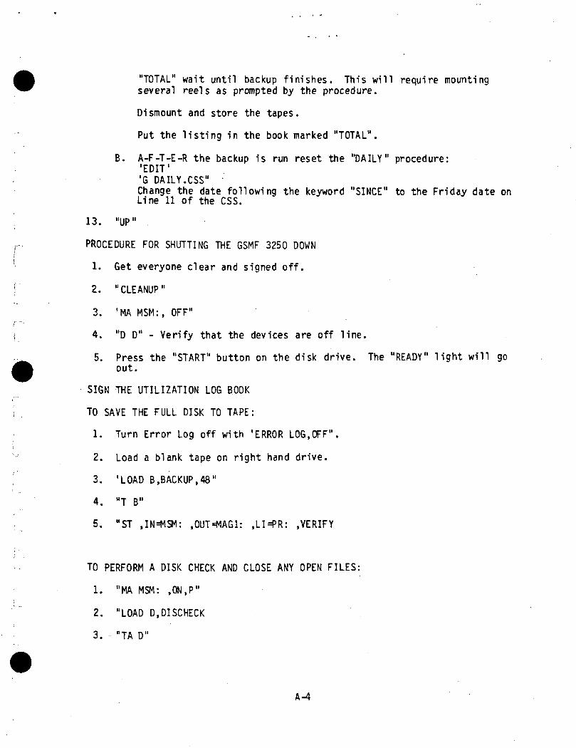
3. Print display page
"PRTDSPLY"
> "0001-0001"
> "END"
4. After new display pages have been created,
"DELETE DFTEMP.LOG"
before starting GSMF system.
A-7

APPENDIX B
ACRONYMS AND TERMINOLOGY

APPENDIX B
ACRONYMS AND TERMINOLOGY
ATE Automatic Test Equipment. (ATE computer is used to designateMitra 6COS host)
BITE Built in Test Equipment
BSR Bite Status Request
CID Computer Interface Device
CDR Critical Design Requirements
CMS Conversational Monitor System (IBM)
CRT Cathode Ray Tube
DBGM Data Base Generation Management
DMA Direct Memory Access
ECOS Experiment Computer Operating System
ECP Engineering Change Proposal
FIFO First In - First Out
GCID Ground Computer Interface Device
GCOS Ground Computer Operating System
GFE Government Furnished Equipment
GOAL Ground Operations Aerospace Language
GSMF Ground Software Maintenance Facility
HAL/S Houston Aeronautical Language/Spacelab
HOL High Order Language
HOST This is a reference to the P-E computer that is the host to theGSMF operation. The reference may also accommdate the SDF-Hostreferences for the Integrated mode descriptions
IPS Instrument Pointing System
KSC Kennedy Space Center
MAC I Monitor, Access, and Control Interface
B-l

Major Cycle
MDTSCO
Mi tra
Module
MSE
MSFC
NASA
PCD
PDR
P-E
PIOL
PPI
SCOS
SDF
SL
SLDB
SMID
SVC
SWID
Task
1MB
UDF
VDU
VM
One second basic time frame under which host computer (P-E. forGSMF) is required to service data requiremennts of ATE/GCID.
McDonnell Douglas Technical Services Company
A computer upon which different operating systems execute(ECOS, GCOS, and SCOS) for the test equipment processing
A portion of software in a computer system which may be indepe-dently described, designed, coded and tested. If may be asubset of a larger set or superset (i.e., a task or a func-tional unit).
Measuring and Stimuli Equipment
Marshall Space Flight Center
National Aeronautics and Space Administration
Payload Checkout Unit
Preliminary Design Review
Perkin-Elmer
Periodic Input/Output Loop
Processor to Processor Interface (A P-E Communication Device)
Support Computer Operating System
Software Development Facility . '
Space!ab
Spacelab Data Base
Simulation Identification
Supervisor Call
Software Identification
A process in a computer which can perform its function inde-pendent of other processes. It may depend on other process fordata or scheduling.
Telemetry Buffer
Unit Development Folder
Visual Display Unit
Vi rtual Memory
B-2

APPENDIX C
SWID RELATION FORM GENERATION PROCEDURE

APPENDIX C
SWID RELATION FORM GENERATION PROCEDURE
The SWID FORTRAN Program extracts ATE subtable data located in the Space-
lab Data Base (SLDB) which resides on the IBM 4341. This data will be re-corded by SWID for each ATE subtable and transcribed to a SEID relations form.
The ATE subtables to be extracted from the SLDB are defined in FigureC-l.
To extract the ATE subtables and generate the aforementioned SWID Re-lations forms, the user will exercise step 1 described in Figure F-l of Ap-
pendix F. This VM/CMS procedure will prompt the user to all ATE subtables tobe addressed and generate this corresponding SWID Relations form.
C-l

SUBTABLE NAME SUBPART
A/AIDA
A/AISC
A/AIMS
A/AOSA
A/DIGDA
A/DIGM
A/DIGS
A/DISDA
A/DISM
A/DORM
A/DOSK
A/GIDA
A/GIMS
A/GISCA/GOMS
A/GOCLA/SOCD
1
11
11
11
11
11
11
11
11
Figure C-l. Subtables and Subparts
C-2
APPENDIX D
STIMULI/MEASUREMENT SWID PAIRS GENERATION

APPENDIX D
STIMULI/MEASUREMENT SWID PAIRS GENERATION
The SWID relations file will contain appended information which definesthe measurement SWIDs affected by a given stimuli SWID (for this reason, theSWID relations file is also referred to as the stimuli/measurement SWID pairsfile in the GSMF documentation). This information will be categorized intofour parts (i.e., SWID, measurement SWID(s), count, and behavior function.The Information, which resides within the stimuli/measurement SWID Pairs File,is collected and compiled through a series of steps involving manual processesof matching and mapping data. The first process is to manually locate astimuli SWID. Once a stimuli SWID is located, information such as groupnumber, subtable name, and SNI will be used to yield a reference to other data
pertaining to the stimuli SWID, namely, measurement SWID(s), measurement SWIDcount, and behavior function.
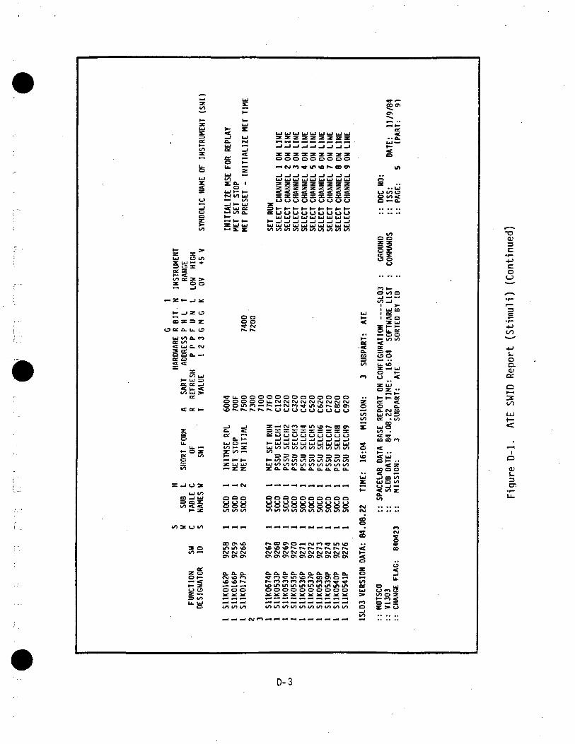
With reference to Figure D-l, Stimuli SWID Number 9245 is one of manySWID(s) in the host database. It is manually found by scanning the databasereport.
Stimuli SWID 9245 is mapped by retaining:1) The predefined group number, which is 11 in this case
2) The subtable name, which is SOCD
3) The SNI, which is "Clear TLM Error Counters."
NOTE: "Counters" indicates more than seven measurement SWIDs will be affectedby SWID 9245.
After obtaining the stimuli SWID information, a scan of the databaselisting is made for the affected measurement SWID. Referring to Figure D-2:
1) A search for an identical SNI (which is "Clear TLM Error Counters" inthis case) predefined in its given group number (which is 11 in thiscase) is found.
2) It is found that three SWIDs, 8197, 8198, and 8199 resulted from themapping and cross reference of stimuli SWID Number 9245. Thus, themeasurement SWID count is 3 and the measurement SWIDs which wereeffected by Stimuli SWID Number 9245 are 8197, 8198, and 8199.
D-l

ocH-CO
o
o
Ito
§ 0. ec o en co t— M z uJO UJ «Z UJ < < — — O O
>• _j *H*t /><o^w jc jo^oe o if» bJ K L b J O £ B C ^ ^ B ^ M « « ^ I > -— Z O U X u. OOC UJ *™^ Q£ & ^t _ _«io — =>Quju .ee u. u. •— z a. H-
~»— oooouJBeoo»->- —
u o in
co z => z:O tt o. U. 13
uj t/) cw tna m«r uj a. PJ2go.-
is,wn uJ
h- UJ a o: —i< u. <=
«v — oo —r o O O — ' O O
O o o. a a.
inu.— ' O O O O O O O o u J O O r - O O O O O O O O
' coo
•r—4->oo
s_oexOJo:
eeo5-
IO
OI
3Ol
i o o o uj o o o to 10 1/1 1/1 «/> o vi n i/> ifl i/) o f) in <j o 10otcsecou.u.u.u.u.u.u.u.u.u.u.u.u.u.u.
QOaoooooppooaooooo o oooooooooo
7 Oto *—
ou oopooppcspppooopooopo
U. UJ — — •o (/) in i
oo
D-2
zto*•""
fr—zzs
to5
teUJ
0
_Joa
co
u o in
Of Z*•• <to 0£ * >•
2 3°
~ z t- _i *
t- _l Z O
m z => ztf cc o. u. ts
LU to o. mCC tO< u c. PJ:« a:o o a. — «or oX
Xto UJ
(x a: _j
ce
tf. ^
u.u. —
1- O Z
g «"to
— — 1 O 3
UJ 1OCD _J UJ=> es Zto 2 <
t- z
to —
O H-— «t>- Z(_) (J
=> toU.U,
UJ
H-
UJ
5 x— J UJ
UJ —ae _j
O t—u. •-
toZ o. i
oUJ I— 1—fNJ tO Ul•» to_J ^- UJ< uj oe•- KO a.
z u; uj— Z Z
o oo oW PJ
«»• u. o oo o o oo o tn en
_J _J0. 5
UJ O —CO H- Z
£ »->-Z UJ UJ
_« —1
o o o888
co en voC\J CVJ CSI
ex ex a.CM to roto 10 r-O o O
co 10 to
UJ UJ UJ UJ UJ UJ UJ UJ UJz z z z z z z z z-J-I-I_I-I_I_I_J_Jz z z z z z z z zooooooooo— cvj «n «• to >c i GO w
UJUJUJUJUJUJUJUJUJz z z z z z z z zz z z z z z z z z
UUOUOULJOO
i . i i . irr.^!rTirTirrirTi^TirTttOCOtOI / t tObOLOtOCOCO
oooooooooooS ft — K S « £ £ £ S £
z»<c<>jrovtnior«-cec^3 X X X X X X X X XCCO(_?O(_3<->O<->(_>O
^UJUJUJUJUJUJUJUJUJto to to co
»-LoLoSl?Locoioiolozo.a.n.o.0.0.0.0.0.
oooooooooo8888888888
r-coeno«4C\jr»>9LntoCVJC\JC\JCMCVJCSICMCMCMC\J
a.txo.cxcxo.eLcxo.a.
o o o o o o o o o o
toto^^to.o.o^toto
UJ
^g
.•oea.CO
to
B m
oI7>bO~
ss.,UJ
r"
CM(M
§
S• •
1— .<0
o
ecUJ
0
CO
eocn
S..oc
.. a.UJ ••*t—0
in
O 'z
.. UJO to 13o to <o — a.
COo a
§1o
O COOCO _J
1 >-i ui es1 OC
^K UJZ t- t-
Sfeg^- ^ ts>
ssZ £ UJ
Z UJ
M t—I— I— aa: <o o.OH CNJ COUJ CM =a • touj oto .SSmCO CD rO
^~ " •< UJOH-..
< zCO O O
-J CD COUJ O CO
<c^zo.I/)
CJ
Q
CO
.,u.J
O ujo *n 3CO 0 Z0- ZZ >• U
^"^^
3C•r"
Coii^^•r-
3
• ™
^7.
0O.QJ
O
I/)
LjJ
<
,_J
1
O
tu3
•?U-
D-3

CL.OCO &e u. O X _J LU t— "-(_> — tl. O O O O — t— H-Z Z => •- Z O — I O Z O - O X < •£ OOJE oo i« uJ O»- — toi^ttt— <c«i c r o u J t — zocb-tsocjcx o to uj
o uj
51 z i: s:
UJ Ul CO.3 u, u. u. u. u, u. u. u, u. u. —J u.Ct CC U- U. Z 2 Z Z U . Z Z Z Z U - Z Z U . U . U . U . U . U . « £ b -t-t-o o oooocooo oo o o o ooo o o u. o
CO CO UJ—J —J U, U, U. U, U. U. U. U. U. U, =« < Z Z U . U . U . U . Z U - U . U . U . Z U . U . Z Z Z Z Z Z C C Zu. u. O O O O o O O O O O O O O O o O O O O O t — O
r» o —cen
UJ
<
K
I=>CO
s«zo
8 4. UJCO U
O CO «c•" O.
lla:
esj CJ CM rv c s i c w r w r v i r > J c u r > j c j ( s j r N j c s j r > j r j r s i c v c j C N J C s j c \ i C N J C N j c j r j r j r \ i c v r \ j * *
(— o o ct *rO U J U J ^ - O
tnco
rot-O co Ocp-1 u> eI Oft < O
=>«•L? O
Lt ^D
5—<
02E (i'f— ^- O£
o c.C. CVI C3UJCJ SOC • CO
UJOCO •
See n
BOO
«J CO COUJO CO
O—' —< CO ZUJ C/) CO CO IVCO *- h- (— OJ
Ol
ro0)
oO.O)
QC
OO
LU
CMI
O
QJ
3CT>
ioiili So§§ofefeooo£ ol.i g
O O O O O O O O O O O O O l S C S O O O O O O Q O O O O O < < t f < 3
- in^or*. codo ^ L f t i D r ^ c o c f t O * — e N j f n w m ^or^.cc
CDCDCOCDCOCOCDCCCDCOCDCCCDCCCDCDCOCDCDCOCCCDOacDCOCDCDCDCDCOCDO
ec
o
X X X X & X X X X X X X X B . O . X X X X X X X X X X X X O . O . Q . B . O C
• -H*^-^»- iPOrof*>ro '^ rororo '* l rovDiolOVO*f> '^ p * ' ' 1 1 ^^ 'n^f*«r^ '**COCOCOCf\>
oooooooooooooooooooooooooooooootoxxxxxxxxxxxxxxxxxxxxxxxxxxxxxxxc
D-4
Referring to the SWID relations form for SWID 9245 in Figure D-3, the
measurement SWID information obtained would be entered as GSMF data base
requirements (i.e., 3 for the measurement SWID count, 8197, 8198, and 8199)
for the measurement SWIDs and T9245 as the behavior function name. This would
constitute the Stimuli/measurement SWID pairs for Stimuli SWID 9245.
The format for this STIMULI/SWID relationship would be indicated in
Figure D-3. When SWID measurements effected are more than three, continuation
is started directly beneath the start of the previous line (indicated in
Figure D-3 as SWID 9999). It must be noted that all measurement SWIDS are
defined in a five character field right justified and behavior functions in a
eight character field left justified. A maximum of fourteen measurement SWIDs
can be accommodated for each Stimuli SWID. (A blank character for purpose of
clarity is indicated by b.)
D-5

GSMF REQUIREMENTS FOR SWID 9245 OF SUBTABLE /SOCD
SYMBOLIC NAME: CLEAR TLM ERROR COUNTERS TM CLR EC
MML-ID: SLLK0322P HW ADDR PI:
SOURCE: GO CD 5170 HW ADOR P2:
DESTINATION: TLM COUPLER AD HW ADDR P3:
REMARKS:
PARAMETER TYPE: 1
COMMAND ARRAY:
5170
RELATED SWIDs SUBJECT TO CHANGE:
GSMF DATA BASE REQUIREMENTS: b308197T9245bb08198T9245bb08199T924509999T9245bbb
GCOS UTILIZATION:
BEHAVIOR FUNCTION REQUIREMENTS:
SCOS/ECOS MODELING REQUIRED:
GCID/BUFFER REQUIREMENTS:
SWID RELATIONSHIP DESCRIPTION
Figure D-3. SWID Relations Form
D-6

APPENDIX E
PCD OPERATING SYSTEM SERVICES
APPEKDIX E
PCU OPERATING SYSTEM SERVICES
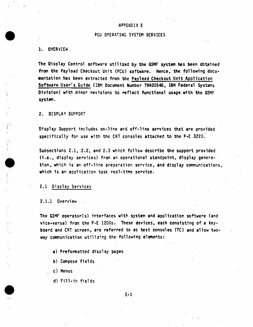
1. OVERVIEW
The Display Control software util ized by the GSMF system has been obtainedfrom the Pay!oad Checkout Unit (PCU) software. Hence, the following docu-nentation has been extracted from the Payload Checkout Unit ApplicationSoftware User 's Guide (IBM Document Number 7940054B, IBM Federal Systems
Division) with minor revisions to reflect functional usage with the GSMFsystem.
2. DISPLAY SUPPORT
Display Support includes on-line and of f - l ine services that are providedspecifically for use with the CRT consoles attached to the P-E 3220.
Subsections 2.1, 2.2, and 2.3 which fo l low describe the support provided(I .e. , display services) from an operational standpoint, display genera-tion, which is an o f f - l i ne preparation service, and display communications,which 1s an appl ica t ion task real-time service.
2.1 Disp lay Services
2.1.1 Overview
The GSMF operator(s) Interfaces with system and application software (andvice-versa) from the P-E 1200s. These devices, each consisting of a key-board and CRT screen, are referred to as test consoles (TC) and al low two-way communication u t i l i z i n g the fol lowing elements:
a) Preformatted display pages
b) Compose f i e lds
c) Menus
d) F i l l - in f i e ld s
E-l

e) 0-line messages
f) 1-line commands
g) Error numbers.
These elements and their general usages are discussed In the followingsubsections. In addition, a layout of the TC keyboard 1s provided (FigureE-l).
x
2.1.2 Preformatted Display Pages
The GSMF system is bu i l t around a set of predefined display pages. Thesepages wil l be titled (first /second lines) based on their function. Otherelements that may be present are descriptive text, menu options, composef ie lds , and f i l l - i n f i e lds . The Display Control software also maintainsGMT and MET/CDT in l ine 1, columns 1-16 and 61-80, respectively, for allactive TC screens.
2.1.3 Compose Fields
Compose fields, areas on the screen denoted by underscores (-), providethe mechanism for the operator to enter data destined for the controllingsoftware. The following items are applicable to compose fields:
a) The entire compose field must be filled prior to depressingany one of three SEND keys.
b) Data entered into a compose field 1s retained across otherdisplays. Compose date may be resent by re-entering as littleas one character.
c) The TAB and BACK-TAB (|*) keys are used to position cursor toIndividual compose fields (including I-l1ne).
d) The cursor must be positioned past the compose field to be sentprior to depressing SEND key. This is performed automaticallyif data is entered into the entire field.
E-2

ORIGINAL 3SOf POOR QUALITY
£tuK
U it)UJ X
85-03-61W
v>vZ«2o w-*£
•* V •
MO tta t-
DnDil ^uuLDi-iD|,D{; EE3.BDnjjj,, EEEE
BBSS
L I
D=D ' giSgD-D: E^E°D'D< py^b:
° i ! ^D^ |BE|
•c
X
c*cC
UICD c,
5CT,
CDU.
E-3

e) Compose fields (data) must be sent Individually, I.e., one ata time.
f) The audible alarm will be heard 1f data 1s sent. If the alarm1s not heard, depress SEND key again. If unsure, depress the SENDkey again since entry will be Ignored 1f field was already sent.
g) If data entered 1s Invalid, a message Indicating such will bedisplayed within the 0-line. Reenter and resend the data.
h) The sending of compose field data may or may not cause a newdisplay to be brought up.
1) Any attempt to enter data into any position on the screen otherthan a compose field (and I-line), will result 1n a keyboard lockcondition.
2.1.4 Menus
A menu 1s defined to be a group of 1 to 16 options selectable for a givendisplay with each option defined textually on one and only one line. Ingeneral, an option line takes on the following form:
.•n
Where T is the text characters describing the option and n Is e number (1-16)Identifying the menu option number. Function keys one (1) to sixteen (16)are used to select individual options; therefore, n also Indicates thefunction key. Usually e new display 1s brought up on option selection butnot necessarily.
2.1.5 Fill-in Fields
Fill-In fields provide one method by which GSMF software communicates withthe operator. These predefined fields (up to 125 per display page) may beupdated with function dependent variable data at any time regardless ofwhether the page is being viewed. Fill-in data is always broadcast to allactive TCs containing a copy of the target display page. Note that allfill-In field data must be sent as ASCII data.
E-4

2.1.6 0-L1ne Messages
Two classes of messages are output to the dedicated 0-l1ne (line 23) by theGSMF software. Information conveyed by a given tiessage 1s function de-pendent and self explanatory. The particular message class (A or B) 1salways Indicated at the beginning of the message.
2.1.6.1 Class A Messages
Class A messages normally Indicate an operational problem that requiresoperator Intervention. Class A messages must be specifically acknowledged(Ref. 2.1.7.2) and are output on a FIFO basis. A Class A message willoverride a Class 6 message on the 0-line. Also Class A messages are alwaysbroadcast to all active TCs.
2.1.6.2 Class 6 Messages
Class B messages are provided for operator Informational purposes or toIndicate a non-critical error. Class B messages are output on a FIFO basisand are acknowledged indirectly upon depressing any function or send key.
2.1.7 1-Line Commands
1-line commands are provided to communicate a specific operator requestregardless of the display page being viewed. The command 1s entered bytabbing to the 1-line, typing a one to four character mnemonic, an optionaloperand, and depressing a send key. Individual I-line commands aredescribed 1n the fo l lowing paragraphs.
2.1.7.1 Error Number Acknowledge (NAC)
The NAC command is used to acknowledge the currently flashing error number(Ref. 2.1.8). No operand is involved and shifted function key one dupli-^cates this command.
E-5

2.1.7.2 Message Acknowledge (MAC)
The MAC command is used to acknowledge the currently displayed class Amessage. No operand 1s Involved and shifted function key 12 duplicatesthis command. A Class A message may only be acknowledged from the TC (1-5)Identified by the number just preceding the Class A Indicator. This 1s thebroadcasting TC (i .e. , the original target TC of the applications task'srequest).
2.1.7.3 Identify Current Error Number ( I D )
The ID command 1s used to Identify the currently flashing error number(Ref . 2.1.8). Entering this command results 1n display skeleton DPOOOOoverriding the current display and error number related text being f i l l edInto an associated f i l l - i n area. No operand 1s Involved and shiftedfunction key three duplicates this command.
2.1.7.4 Display (D)
The D command is used to refresh the screen with a specified display page,I.e., override the current page. The operand, a 1-4 digit number, speci-fies the display page .
2.1.7.5 Load a Task ( L O )
The LO command is used to load the task named 1n the 1-8 character operand.The named task must be a task f i l e (TSK extension) and contained on volume
MSM1.
2.1.7.6 Start a Task (ST)
The ST command is used to start a task named 1n the 1-8 character operand.The named task must have been previously loaded (Ref. 2.1.7.5).
2.1.7.7 Cancel a Task ( C A )
The CA command .is used to cancel a task named in the 1-8 character operand.
E-6
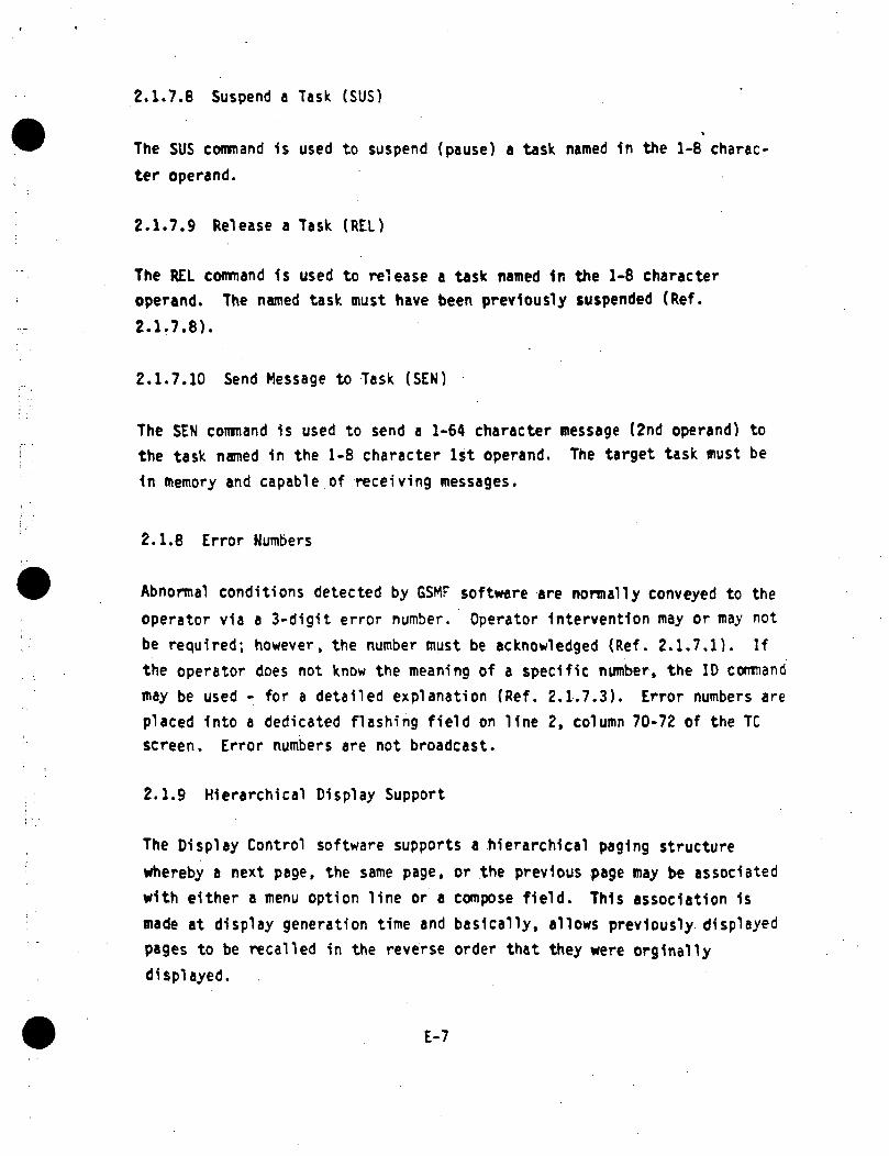
2.1.7.8 Suspend a Task (SUS)
The SUS command 1s used to suspend (pause) a task named In the 1-8 charac-ter operand.
2.1.7.9 Release a Task (RED
The REL command 1s used to release a task named 1r. the 1-8 characteroperand. The named task must have been previously suspended (Ref.
2.1.7.8).
2.1.7.10 Send Message to Task (SEN)
The SEN command 1s used to send a 1-64 character message (2nd operand) tothe task named 1n the 1-8 character 1st operand. The target task must be1n memory and capable of receiving messages.
2.1.8 Error Numbers
Abnormal conditions detected by GSMF software are normally conveyed to theoperator via a 3-digit error number. Operator Intervention may or may notbe required; however, the number must be acknowledged (Ref. 2.1.7.1). Ifthe operator does not know the meaning of a specific number, the ID commandmay be used - for a detailed explanation (Ref. 2.1.7.3). Error numbers areplaced Into a dedicated flashing field on line 2, column 70-72 of the TCscreen. Error numbers are not broadcast.
2.1.9 Hierarchical Display Support
The Display Control software supports a hierarchical paging structurewhereby a next page, the same page, or the previous page may be associatedwith either a menu option line or a compose field. This association 1smade at display generation time and basically, allows previously displayedpages to be recalled in the reverse order that they were orglnallydisplayed.
E-7

2.1.10 Multiple SCS Support
•*
The display control software in reality 1s one to five independent tasks(reentrant) (DSPLCTLl - DSPLCTL3) with each supporting TCI - TC3, re-spectively. Keyboard actions at a given TC result 1n parameter blocksbeing built that contain the specific TC ID (1-3). These parameter blocksare passed to and interpreted by the associated application tasks. Inresponse and 1n general, such application tasks -should append the TC IDpassed, to the Display Control task name (DSPLCTLN) required within theservice request block when communications back to the TC 1s required. Indoing so, the application has performed its only requirement In support ofmultiple TCs.
2.2 Display Generation
2.2.1 Overview
Utilizing a set of supplied macros, the applications programmer defines thetext and control information necessary for building the display page (seerelated macros). These macros then become Input to the P-E 3220 MacroProcessor which in turn generates a source file suitable for Input to theCAL assembler. In addition, an assembly listing of the generated assemblerstatements reflecting the defined display 1s also produced. Error messagesmay or may not be embedded within this listing. If present, such messageswill be self-explantory.
Also, the display must be 'established1 1n order to be recognized as aviable display. This is accomplished through the P-E 3220 TaskEstablishing Task (TET). The object file created as output from theassembly phase becomes input to TET. The output file produced from thisphase constitutes an established display and may be placed on the TC screenand/or the printer utilizing the PRTDSPLY off-line utHty (Ref. Sub-section
6.12).
Two CSS procedures are available to control the entire process of displaygeneration and establishment. Figure E-2 shows the use of these procedures
E-B

ORIGINAL 5SOF POOR
85-03-6130
c,1
oc
1C
ft.1
c,-c;
iu.1
ft.1
tr-
E-9

1n the Display Generation and establishment process. It should be notedthat the display must be established on volume HSM1 in order to be accessedby Display Control software.
2.2.2 Display Generation Macros
Six (6) macros are provided in support of Display Generation. Thesemacros, described in subsequent paragraphs, as as follows:
a) TEXT macro
b) TEXTEND macro
c) OPTION macro
d) COMPOSE macro
e) LEGAL macro
f) DSPLYEND macro
2.2.2.1 TEXT Macro
One or more (up to 22) TEXT statements are used to communicate the textportion of a display. A TEXT statement has the following format:
C'C<1TEXT LN-N.LINE"' ASCII TEXT CHARACTERS —'
The line number (LN=N) is optional and may contain a value of 1-22.If LN=N is specified, it must be at least one larger than the previous
line number (explicit or Implied); If LN*N 1s not specified, then theImplied line number 1s one greater than the previous line number. TheImplied line number of the first TEXT statement 1s one (1).
Text characters specified 1n the "LINE*" parameter must be enclosed inapostrophes and may inclu'> any valid ASCII characters with the exception
E-10

of apostrophes. Certain ASCII characters however, are used as special indi-cators. These characters and their usage 1s as follows:
• Underscore {_) - Indicates compose fieldAt sign ($) - Indicates option line.Exclamation point (!) - Indicates fill-In fieldDollar sign ($) - Indicates blinking field.
For the purpose of clarification, the definition of compose field,fill-in field, and option line 1s presented here along with appropriaterules/restrictions regarding the usage of such.
a) Compose Field
An area within a text line where variable TC keyboard datamay be entered with the Intention of passing such data to aGSMF applications task. Two or more consecutive underscoresymbols shall be required of which the first shall be un-available for keyboard entry. That underscore shall beoverridden with an attribute character and shall be display-ed as a blank. In addition, the character Immediatelyfollowing the last underscore shall be overridden for thesame purpose as well. Finally, only one compose field perline is allowed and sixteen (16) per display.
b) Option Line
Any l ine in which the P symbol 1s detected. The purpose ofan option line is to indicate that an associated TC functionkey (1-16) may be used to signal a GSMF applications taskand/or signal Display Control to refresh the TC screen withanother display. The specific function key number (1-16) 1scomputed based on the numerical order of prior option lines
and relative to one (1). This number Is then Inserted intothe line immediately following the '§' symbol. Either one
or two text characters wi l l be overridden. The '(?' symbolshould not appear 1n positions 78-80 of the l ine. Also, themaximum number of option lines permitted in a display 1ssixteen and compose fields are not allowed 1n option lines.
E-ll

c) F i l l - in Fields
F i l l - In Fields are defined to be f ields that applicationtasks may request the placement of f i l l - in data. Such af ield is ident i f ied by arranging one or more consecutive '!'symbols in the proper position of the text T1ne (i.e.,through the "LINE*" operand). Hultlple f i l l-In fields maybe arranged on a single line or an entire line (80characters) may encompass a single f i l l - in field. Also,there is no restriction with regard to compose fields oroption lines. The maximum number of f i l l - In fields perdisplay is 125. Fi l l - in fields win be addressed byapplications tasks through a fill-in field number. Suchnumbers wi l l be assigned by the display generation processand will be 1-N depending on numerical sequence of thespecific f i l l - i n f ie ld with regard to prior f i l l - in f ields.F ina l ly , u n f i l l e d f i l l - i n f i e lds will be displayed as blankson the 1C screen.
The '$' symbol shall be used within a text I1ne(s) toindicate the beg inn ing and end of a b l ink ing area ( f i e l d ) onthe screen. One byte wil l be (for each $) dedicated for thegenerated control code (b l inker on/blinker off) and shall bedisplayed as a b l a n k . There are no restrictions on the '$'usage except as fo l lows:
1. No compose f ields should be defined within a b l ink ing f i e ld .2. The '$' symbols must be paired.
2.2.2.2 TEXTEND Macro
The purpose of the TEXTEND macro 1s to Indicate the end of TEXT macroprocessing for the generation of a given display.
The TEXTEND macro statement must Immediately follow the last TEXT macrostatement and has the fol lowing format:
C.C.10TEXTEND
E-12

No operands are required for this macro. Its primary function 1s to causethe generation of required control Information such as total text arealength and fill-in field addresses and lengths.
2.2.2.3 OPTION Macro
The purpose of the OPTION macro 1s to communicate the 'next task' and/or'next display' that is to be associated with a particular option line(function key) within the display text.
There must be one OPTION macro specified for each option line within thetext of the display. Such statement(s) must also Immediately followthe TEXTEND macro. In addition, the OPTION macro statement(s) must bespecified in the same numerical sequence for which the associated optionline was positioned. That is, the first OPTION macro 1s associated withthe first option line, the second OPTION macro with the second option line,etc.
The OPTION statement has the following format:
C.C.10OPTION TASKNAME,DSPL
The first operand is optional and if specified, must be the name ofthe task to receive control upon depression of the associated TC functionkey. The second operand is required and may be SAME, PREV, or a one tofour digit display number. SAME may be specified to Indicate to displaycontrol that the current display Image 1s to remain on the TC screen.PREV Indicates the previous display Image 1s to replace the current Image.
2.2.2.4 COMPOSE Macro
The purpose of the COMPOSE macro 1s to conmunicate the 'next task1 and/orthe 'next display1 that 1s to be associated with a particular composefield (keyboard entered data) within the display text.
E-13

ORIGINAL PAGE 53OF POOR QUALITY
There must be one COMPOSE macro specified for each compose field within thetext of the display. In addition, each COMPOSE macro statement must bepaired with a corresponding LEGAL macro statement (see LEGAL macro). TheCOMPOSE/LEGAL pair grouping must Immediately follow any OPTION statement(s)that may be present. Each COMPOSL/LEGAL pair must also be specified 1nthe same numerical sequence for which the associated compose field waspositioned. That 1s. the first COMPOSE/LEGAL pair 1s associated with thefirst compose field, the second COMPOSE/LEGAL pair with the second composefield, etc.
The COMPOSE statement has the following format:
C.C.10COMPOSE TASKNAKE.DSPL
where the first operand 1s required and must be the name of the task toreceive control upon TC keyboard data being entered Into the associatedcompose field. The second operand 1s required and nay be SAME, PREY, ora one to four digit display number, I.e., next display. SAME may bespecified to Indicate to Display Control that the current display Image isto remain on the TC screen. PREV indicates the previous display image isto replace the current Image.
2.2.2.5 LEGAL Macro
The purpose of the LEGAL macro 1s to Indicate compose field parameter limitsand compose field validation and conversion requirements.
There must be one LEGAL macro specified for each compose field within thetext of the display. In addition, each LEGAL macro statement must bepaired with, I.e., Immediately follow, an associated COMPOSE statement(see COMPOSE macro). Also, the COMPOSE/LEGAL pair must be specified 1n thesame numerical sequence for which the associated compose field was position-ed In the text.
A compose field, for the purpose of validation and conversion, consistsof one or more parameter fields. For the purpose of validation, eachparameter may consist of one or more sub-parameter fields. With this inmind, the LEGAL statement then requires the following format:
E-14

C.C.10LEGAL (P1),(P2),. . ..(Pn)
PI 1s required and represents the operand describing the validationand conversion necessary for the first (or only) parameter field withinthe associated compose field. P2-
pn would describe additional parameter
flalrie
Each P operand has the following format:
where: « is the type of parameter to be passed to the applicationtask.
6 1s the type of date entered (sub-parameter type) for this« field.
n is the number of characters in a sub-field.
•y 1s the legality check data for a sub-field.
« «ay be:
C for characters.F for a fixed point number (Integer only).E for a single precision floating point number.D for a double precision floating point number.H for hexadecimal digits 0-9 and A-F.
6 may be:
A for alphabetic charactersB for binary digits (fl or 1).D for decimal digits (fl-9).M for all type characters.H for hexadecimal digits B-9 and A-F.
E-15

•y '1s either 6 or ( f i^f ig )
6 1s an acceptable field contents.6, 1s the lower l imit of an acceptable field contents.6. 1s the upper l imit of en acceptable field contents.
Display Control shall perform validation of sub-field data entered basedon Y data. This validation for a field of proper type shall be of theform:
LEGALITY CHECK « (^[,^3 . . •[•?„])f
If the field passes one of the content or range checks, 1t shall be accepted.
Finally:
1 + In « number of '_' (underscore) symbols 1n a given compose field.
An example of a LEGAL statement 1s:
C.C.10 C.C.72
LEGAL (C,A,1,(A,B));(C,A,1,(H,F,Z)),(C,M,2.(S1,S2)), 2(E.M.1.(+,-).D,3.,M,1f..D,l,.M.2,(E*.E-).D,2). Z(C,M,2,(T1;T7,X1;X7))
This LEGAL statement defines the validation/conversion required for a composefield with five parameters. The first three ire character fields, the fourth1s a floating point number, and the fifth 1s a character field. The firstparameter 1s one alphabetic character that can be either A or B. The fourthparameter describes a floating point number and consists of seven sub-fields.A typical entry for this parameter might be:
•O23.4E+11
The fifth parameter 1s character data that can be within the range Tl to T7or XI to X7.
E-16

2.2.2.6 DSPLYEND Macro
The purpose of the DSPLYEND macro is to Indicate the end of the DisplayGeneration process.
The DSPLYEND macro statement must be the last macro statement within thegroup. The statement has the following format:
C.C.10DSPLYEND
No operands are required for this macro. Its primary function is to causeInitiation of final validation on the overall Display Generation process.Specifically, the number of option lines vs. number of OPTION statementsand the number of compose fields vs. number of COMPOSE/LEGAL pairs arechecked.
2.2.3 Display Generation Example
The following example illustrates the necessary control statement requiredto generate a typical test console display.
E-17

ORIGINAL PAGE SSOF POOR QUALITY
At least one blank
C.C.10 OPERATION . OPERAND(S)
Ml IBS
TEH
TEXT
TEXTEND
OPTION
OPTION
COMPOSELEGAL
COMPOSELEGAL
Defines nacro library L.l).
• TFYT '... IbnI ... Defines text, etc.(1-22 statements)
••.TEXT.•.
Defines end-of-text
TASK.OSPL
One statement for eachoption line
TASK.'OSPL
TASK.DSPL(LEGAL DATA)
One compose/legal statementpair for each composefield
TASK.DSPL(LEGAL DATA)
DSPLYEND
END
Defines end-of-display
Required for assembler
It should be noted that the very first (MLIBS) and very last (END)statements are not display generation macros; however, such state-ments are required Input for proper operation.
E-18

2.3 Display Communications
2.3.1 Overview
Display communications 1n GSMF Involves two distinct areas. These are:
a) Communicating TC keyboard entries to associated target
application tasks.
b) Communicating TC screen request made by application tasks.
Item 'a1 above may be initiated by either selecting a menu option (function
key) or sending compose field data. In both cases, a parameter 11st 1s
constructed and the address passed to the application task via the SVC 6
Q-PARM facility. It is up to the application task to decode and act
accordingly on the passed parameter list. Item 'b' above 1s Initiated by
the application task through the same facility and involves the passing of
a request block to a specific Display Control task. These Display Controlcommunications services are described in detail 1n subsequent paragraphs.
2.3.2 Menu Option Handling
Upon fielding the menu option selection (function key), Display Control S/VJexamines associated display page control information to determine whethercommunications with a target application task 1s required. If not, then'next page' processing is performed and no interface to an application task1s established. If an application task 1s associated however, then a'function key' parameter list, as described 1n Figure E-3, 1s constructedand passed to this task. It 1s assumed that the applications task 1scapable of receiving a parameter list (i.e., conforms to the rules of aqueue service interrupt handling task as described In Section 3 of theInterdata OS/32-MT Program Reference Manual, Pub. No. 29-613).
E-19

BYTE
PARK TC RESERVED FK *
4-DIGIT DISPLAY 1
F I E L D D E S C R I P T I O N ' S :
1. PARK ID.
2. TC ID.
3. FK *
4. 4-D1GIT D I S P L A Y
- X'02'f Identifies parameter 11st type.
- ID (1-n) of associated test console.
- Binary number (1-16) of function key that was ?depressed. g
c.- Display Identifier for which this parameter £
11st 1s associated. ~"
Figure E-3. FUNCTION Key Parameter List
E-20

If an error 1s detected on attempting to pass the parameter, the Display
Control S/W assumes the associated task 1s not 1n wemory. In this case,
Display Control S/W will attempt to load, start the task, and again passthe parameter. If an error 1s detected during this phase, an appropriate
Class B message 1s output and no further action 1s taken.
2.3.3 Compose Field Data Handling
As with menu option handling, the communications to the application taskfor a compose field entry 1s performed 1n exactly the same manner. How-ever, prior to construction of the associated parameter list, validation
and conversion is performed on the entered compose data according to the
LEGAL data specified at display generation time.
Figure E-4 illustrates the parameter 11st generated and passed to the
applications task. In addition, Tables E-l and E-2 are provided to furtherclarify the automatic validation and conversion performed on a compose
field entry.
Both parameter lists (compose data and function key) are built 1n storageobtained from CMPOOL (Ref. 5.3.2). It is the application task's respon-
sibility to properly release this storage once processing 1s complete.
2.3.4 Display Applications Services
The Display Control software supports a variety of display related andapplication task request services. These Include the following:
1) Fetch display page to memory
2) Display specified page Image
3) Update display page (single fill-In field)
4) Update display page (multiple fill-In fields)
E-21

•VTE 0
COM'OSt FIELDHEADER
COMPOSE FlfLDDESCRIPTOR \
PARVID E RESERVED
••DIGIT DIP LAV NUMBER IASCIDC.F.NUMBER
N.P.OFFSET
NUMBEROF PARMS
RESERVED
RESERVED
T L
; PARAMETER NUMBER 1 DATA |
K.P.OFFStT RESERVED T L
PARAMETER NUMBER 2 DATA
K*.OFFSET RESERVED T L
PARAMETER NUMBER* DATA
ORIGINAL IBOF POOR QUALITY
PARAMETER HDR 1
PARAMETER MDR 3
PARAMETER HDR K
FltLt)
J. PAR* IT.
2. TC ID.
J. 4-D1GIT
<• C.F. t
5- « PARKS
6. H.t. orrsci
7. T (TTPC)
8. L (LENGTH)
9. PARAMETER DMA
- X 'O l ' . ld*ritifi*i pir»»flfr lilt type.
- ID (ASCII J-n) of istocUtefl Wit centolt.
. D1SF1AT IDENTiriER (ASCII 0000-1999)
- Compost fuli nuBbf (t>lnirr l-n) irlu respect to maericil Mqucnce ofentire iet of coapoie f1«lcs In dttp)*j>.
. fester of piraMtert (p1n«r, 1-n) cOBpr<s1n$ l«toc1<U<J COBpOM fltU.
- Meit pir«Mtrr offset (bltury). I.e., vilue te be tttrt te »fldrejs of tMsfieli In order tc *dareis neil p«r«Mter hdr. A rero (X'00'1 ttlytIndtcttes this u list p«r*»eier for «ss«c1it«d eoapose fteld.
. Type of ptrvieter (ASCII); ••; be C-CMr*cter, F-flsed point. D-Otl prec.floitln; pt.. t-Sjl prec. flMttng pt.. N-tacxtdcc<Ml .
- Nutter of bytes (btntry) In p«r«eur.
- Keyboard entered diti In forvit deslgmtcd by eco«ers1on rtqu1r«MntsSt1pul«ted *ien dlspli/ MS tener*ttd.
Figure E-4. COMPOSE Field Entry Parameter List
E-22

Table E-l. Display Compose Field Sub-parameter Validation
TYPE VALIDATION
A-Alphabetic
B-Bina'y
D-Dec1mel
H-Hexededmil
M-Mixed
Each character of Input sub-parameter
1s tested for alpha (A-Z) restricted.
Each character of Input sub-parameter
1s tested for binary (0 or 1) restricted.
Each character of Input tub-parameter 1s tested for
decimal (0-9) restricted.
Each character of Input sub-parameter Is tested fo-
hexadecimal (0-F) restricted.
All characters are valid. No automatic validation 1s
performed unless an actual or range comparator!s) MBSspecified when display was generated.
eL-
Ec
E-23

Table E-2. Display Compose Field Parameter Conversions
POOR
TYPE CONVERSION
C-Character
F-F1xed Pt. *
(Integer only)
E-S1ng1e-
Predsior,
nt. Pt.
D-Double -
Precision
FH. Pt.
H-Hexadecimai
No conversion done. Character string alignedon full word boundary and passed.
Value must be an Integer with an optional sign
onl>. The value 1s converted to a 2's complementbinary number and passed 1n a full word.
Value Bay be a signed Integer, fraction, or
mixed number. Optionally, exponent may bespecified. The value 1s converted to a
floating pt. number (characteristic andfraction) end passed In a fullword.
as "I" except converted value 1s a 6«-b1t
number and 1s passed as a double-word.
Each Input character 1s translated to Us corres-ponding hex value; I.e., 0-F«00-OF. The 4 MSBS ofeach character are then removed, the string packedand passed aligned on full word boundary. !
£
* Fixed point fractions are not supported, I.e., only Integers.
E-24

5) Initialize fill-in fields (all)
6) Output Class A message»
7) Output Class B message
8) Output condition/error number
9) Compose field initialize (single)
10) Compose field Initialize (all)
As previously mentioned, all requests are made by passing an appropriatelyformatted request block. This request block must be acquired from CMPOOL.Therefore, the application task must be properly linked with the CMPOOLtask common. Subsequent paragraphs describe each of the various services1n detail. In addition, Figure E-5 and Table E-3 describe the requiredrequest block. It should be noted that the modifier bit (bit 1) of requestservice code (RSC) is used for requests 3, 4, 6, and 7. If set to a 1, itwill Indicate that Display Control S/W is to free the associated data area(message or fill-in data area) pointed to by the R.B. data addr. field(RB+20).
2.3.4.1 Fetch Display Page to Memory
Execution of this service will cause the specified display page to befetched Into the display stack area of memory unless 1t 1s already 1nthe area. Use of this service 1s limited since 1t 1s performed auto-matically on all other service requests Involving a specific displaypage.
2.3.4.2 Display Specified Page
Execution of this service will cause the specified display page to befetched to stack area (if not already there) and placed on the TC screenbeing controlled by the target display control task (I.e., overrides theexisting Image).
E-25

ORIGINALOF POOR QUMJW
iYTE
0
48
12
16
16
20
0 1 2 3
RBID | RSC | RCC I SCN
TASKID
DISPLAY ID
CONDITION/ERROR NUMBER
FF NO. | UNUSED
DATA ADDRESS
DUAL USAGE WORD
FlEiC MEANING
1. RB:D • X'Or. identifies this control block as • Display Control request block
2. RSC - Request service code. Identifies specific Display Control function to beperfonneo (tee Table f-3).
3. RCC - Request completion code. Indicates completion type (successful, unsuccessful)of request.
4. SCK - Service completion notification.'
5. TAS* ID - Eight-byte nane of requesting task. Required If TC 1ndtc*t*s queue and/orrelease.
6. DISPLAY ID - Four-digit ID (name) of target display (required for ill requests except 6, ?,and 6).
7. CONDITION/ERROR * • Fou'-digit ASCII error number. Used to Indicate specific errors or conditionsAetectee by applications.
B. FF I • Fill-In field number, binary 1-N. (Also used U Indicate tingle coapost fieldtc be reinitialized.)
9. DATA ADDRESS * - Address of fill-in data or one-line Message.
• As «1t»i this request block, the data address 1f used Mist point U «n aret within the globalWPOO^. Furthermore, the are« Bust be fulltwrd aligned »1th the first too bytes ecnuming the 1engW>(binary) of the succeeding data.
Figure E-5. Display Control Request Block
E-26

I/)I/)eo
om
ft>o-
ft>
iUJ
4>
eBE
fe
U.'
U.
ec
ec
iecoSH-
O
b.
bJ
O
CL
O
§
#CK
UlO
eet«
ORIGINAL p/iQir Js?^Jf* Df\f\n *"
65-03-6135
1o.
s-"c.
k f
X
IT
f^
1/1
ec
fc?coVI
i5•ft
X
Aft
er d
ispla
y pa
ge o
n TC
scre
en u
pdat
ed I
nclu
ding
any
broa
dcas
t
X
X
X
*
9
b.
u!
I•n
iivn*
X
X
X
*Ǥu!iJ
*1
Ii
X
Afte
r M
essa
ge 1
sac
know
ledg
ed b
y op
erat
or(m
e co
Mm
and)
X
Aft
er
Mes
sage
Is
ackn
owle
dged
by
oper
ator
(any
K.B
. act
ion)
X
Afte
r nu
aber
Is
ackn
owle
dged
by
oper
ator
(MAC
com
man
d)
X
Aft
er
dis
pla
y p
age
on
TC
scre
en u
pdat
edIn
clu
din
g a
ny b
road
cast
X
X
San
e as
sin
gle
C.P
.In
itia
lize
abo
ve
X
egg £^_ £ S S g 8 o
1= is I2 1- I- I- |- Is i£ i"f e
5 1 2 rX ^ « ^ « ^ " ^ ^ ^ ^ «
^ y ^i'S ^—1 S S ^t ^> 1 """CL O. «^ f — *f- •* — *J • c c2 •• » •- t'VI in — C k- — »- W. K ^ |Z S¥ IkM Li. M— e— OP •• u t> tss • ^» »O>. «" C K C *- 4> ».- f »i— *> C1 —
&> .^ IB ^x *V ^ .CL <c^ C^ 9C> 9&i 9L B^cvi Be|T 00. S a. k. S o. o. »-b. ££ OX Ci £»•-• £ —
1-27

2.3.4.3 Update Display Page (Single Fill-in Field)
Execution of this service will cause the specified display page to befetched to stack area (1f not already there). The specified field (FFI)1s then updated with the data pointed to by the request block (data addr.42).If the page 1s also being viewed on any active TC screens, then thoseImages are updated as well (i.e., broadcast). Validation 1s performed priorto the update operation to Insure the specified F.F. I and data length(1st H/W of data area) corresponds to a valid f11l-1n field number or length forthe display. The request block RCC field 1s set to X'W or X'081 respectivelyif the validity of these Items cannot be established and assuming TC indicatedpost RCC as part of service complete notification.
2.3.4.4 Update Display Page (Multiple Fill-in Fields)
Execution of this service 1s handled exactly as with a single fill-in fieldupdate request with the following exceptions:
a) F.F.* in request block is used to Indicate the 1st of N contiguousfields.
b) Data length (1st H/W of data area) specifies total compositelength of contiguous fields to be updated. This length mustbe the exact length and be followed by the exact amount ofdata required to fill all N fields.
2.3.4.5 Initialize Fill-in Fields (All)
Execution of this service is performed for the specified display pagemuch like the multiple fill-in field update service. However, no F.F. #nor data address is required in the request block. All TC screenswith target display page being viewed will be affected (I.e., service isbroadcast). Also, no single fill-in field initialize service is providedsince this can be accomplished with the single fill-in field update re-quest by simply supplying ASCII blanks for the data.
E-28

2.3.4.6 Output Class A Message
Execution of this service will cause the specified message to be scheduledfor output to the 0-l1nes of all active TC screens. Scheduling 1s on aFIFO basis; however, any active Class B message will be overridden. If themessage 1s greater than 72 bytes It-1s truncated. As with f1ll-1n data,the message length and succeeding message 1s addressed through the dataaddress field of the request block.
2.3.4.7 Output Class B Message
Execution of this service is performed exactly as with a Class A messageexcept for the broadcast feature. The Class B message 1s output only tothe TC screen being controlled by the target display control task.
2.3.4.8 Output Condition/Error Number
Execution of this service will cause the specified error number (Ref.2.1.8) to be scheduled for output on a FIFO basis to the TC screen beingcontrolled by the target display control task. If a user Intends to usethis service in a new application task, then consultation with the systemprogrammer is required since the number must be assigned and message textmust be placed into the off-line file (Ref. 2.4).
2.3.4.9 Initialize Compose Field (Single)
Execution of this service will cause the compose field, as specified bythe F.F. i field of the request block, to be reset to underscores (_)for the target display page. If this page 1s being viewed on any TCscreen, then it is reset on those screens as well (i.e., broadcast). Thecompose field specified must be a valid compose field for the specifieddisplay page. RCC=X'04' is posted if not and assuming post RCC wasspecified by the SCN field.
E-29

2.3.4.10 Initialize Compose Field (Al l)
Execution of this service is handled by the Display Control software
exactly as 1n 2.3.4.9 except that all compose fields for target displaypage are reset. The compose field number (F.F. # field) 1n request block1s not required. Use of this service as well as the single field resetservice 1s limited since resetting a compose field 1s not required beforereentry of compose data 1n that field. Also, the operator can reset com-pose fields on a page being viewed at any time via shifted function keyfour.
2.4 Error Number Message Text Generation
This sub-section defines the method by which error (or unusual condition)message text is generated to coincide with display error numbers (Ref.
2.1.8).
These messages, intended to provide meaning for error numbers, are gener-ated and maintained in a disk file on volume MSM1: and named ERRORHSG.TXT.
This file has the following characteristics:
a) File has been initialized to 1000 records (blocks), each 256Bytes in length.
b) Each record contains message text for a corresponding errornumber in the range of 000-999.
c) Records that have not been updated contain text Indicating NOTDEFINED.
d) Message text from record will be used as fill-In data for display'DPOOOO1 by Display Control 1n response to an ID I-line command,Ref. 2.1.7.3 and Figure E-6.
A utility update program (MFUPDATE) 1s provided on the P-E 3220 1nconjunction with the CSS procedure rFUP to perform ERRORMSG.TXT file
E-30

ft.I/J U
0.
2LJo
KLJC
15«tou
uE
C
10
O
v>C
a.
oCO
t,cr
ci.c
reoir.
C.'3
1-31

maintenance in non-realtime mode. This program and procedure require acard Image Input file that adheres to the format given 1n Table E-4.
At least one MSG line (statement) 1s required. Also, the set of Inputstatements may consist of mul t ip le subsets to allow updating of multiplerecords. The /* statement denotes final end of input. In addition,records may be updated 1n any order.
E-32

Table E-4. Program MFUPDATE and Procedure MFUP Card Image InputFile Example
Totalof240Bytes
C.C.I
NI5SEOI!
T
T
T
T
T
T
C.C.40
T
T
T
T
T
T
/END
HSG LINE 1MSC LINE 2HSG LINE 3HSG LINE 4
NSfi LINE 5KSG LINE 6
Where: NNN' 1s « 3-dig1t error number «nd T 1$ nestage text characters (ASCIIalphanumeric or special characters).
E-33

APPENDIX F
GSMF DATA BASE GENERATION

APPENDIX F
GSMF DATA BASE GENERATION
1. OVERVIEW
Prior to the actual generation of the GSMF data base certain proceduresmust be executed. These procedures will properly create data which will be
used in the creation of the GSMF Data Base. Basically these are five areaswhich must be addressed by the user to satisfy these apriori data re-quirements. Thse areas are as follows:
1) SWID Relations Forms2) SWID Pairs File3) SWID Data File4) Run Documentation File5) SWID Ini t ia l Data Fi le
The data output from the aforementioned areas shall be generated within
the IBM 4381 VM/CMS environment. This allows the user to be prompted forinputs in an interactive conversational atmosphere. The inputs required arebasic and minimal and are tabulated in Figure F-l. It is assumed that theuser is familiar with the IBM 4381 VM/CMS interactive system.
The following is an explanation of each of the aforementioned areas andthe steps required for their respective data generator.
NOTE: All steps mentioned in the following paragraphs must be executedby the user on numeric ascending sequence;
1.1 SWID Relations Forms/SWID Pairs File
Once the SWID Relations forms as explained in Appendix C have been gener-ated, Step 1 of Figure F-l, then the SWID pairs file for a given Stimuli canbe defined. The SWID pairs file as explained in Appendix D defines Stimuli/Measurement SWID relationships and their incorporation into the SWID Relationsform. The process used to accomplish this is defined in steps 2-4 of FigureF-l which will selectively display the SWID Relations form for a given ATEsubtable on the IBM terminal for editing and then save the new version on IBM4341 for disk eventual GSMF data base addressing.
F-l

ORIGINAL PAGE 53OF POOR QUALITY
Step Procedure
1 SWDPART
2 SPRSIN
3 SPRSMEM
4 SWDPRS
Function
GENERATE A SWID RELATIONS FORM FOR AGIVEN ATE SUBTABLE IN IBM 4341 DISKDATA SET GSMF.SWDPRS.PARTS (MS#TBL)WHERE # IS THE MISSION NUMBER
TBL IS THE ATE SUBTABLE NAME
OBTAINS SWID PAIRS MEMBER TO BEUPDATED FROM OS DATA SET GSMF. SWDPRS.PARTS (MS#TBL) WHERE * IS THE MISSIONNUMBER
TBL IS THE ATE SUBTABLE NAME
PUT UPDATED SWID PAIRS NUMBER IN OSDATA SET GSMF.SWDPRS.PARTS (MSfTBL)WHERE # IS THE MISSION NUMBER
TBL IS THE ATE SUBTABLE NAME
PUT ALL SWID PAIRS MEMBERS IN OS DATASET GSMF.SWDPRS.PARTS (MS#)WHERE # IS MISSION NUMBER
Inputs Reference
SWD PART APPENDIX C# .
TBL
SPRSSINI
TBL
•APPENDIX F
SPRSMEM APPENDIX F
TBL
SWDPRS APPENDIX F
5 SMIDIN
6 SM1DMEM
7 RDOC IN
8 RDOCMEM
9 INITDAT
10 INITDATM
11 GSMFDB
OBTAINS SMID DATA MEMBER TO BEUPDATED FROM OS DATA SET GSMF.SMID.DATA (M#); WHERE # IS MISSION NUMBER
PUT UPDATED SMID DATA FILE MEMBERIN IBM DISK DATA SET GSMF. SMID. DAT A(M#); WHERE # IS THE MISSION NUMBER
OBTAINS RUN DOCUMENTATION MEMBER TOBE .UPDATED FROM IBM DISK DATA SETGSMF.RUN.DOC (M#); WHERE # IS THEMISSION NUMBER
PUT UPDATED RUN DOCUMENTATION-MEMBERIN IBM DISK DATA SET GSMF.RUN.DOC(M#); WHERE # IS THE MISSION NUMBER
OBTAINS SWID INITIAL DATA FILE MEMBERTO BE UPDATED FROM IBM 4341 DISK DATASET GSMF.SWDINIT.DATA (MSf); WHERE #IS THE MISSION NUMBER
PUT UPDATED SWID INITIAL DATA FILEMEMBER IN IBM 4341 DISK DATA SETGSMF.SWDINIT.DATA (MS#) WHERE # ISTHE MISSION NUMBER
GENERATE GSMF DATA BASENOTE: # IS MISSION NUMBER
SMIDIN#
SMIDMEM#
APPENDIX F
APPENDIX F
RDOC IN APPENDIX F
RDOCMEM APPENDIX F
INITDAT APPENDIX F
INITDATM APPENDIX FI
GSMFDB APPENDIX F
Figure F-l. Setup Mode VM/CMS Procedures
F-2
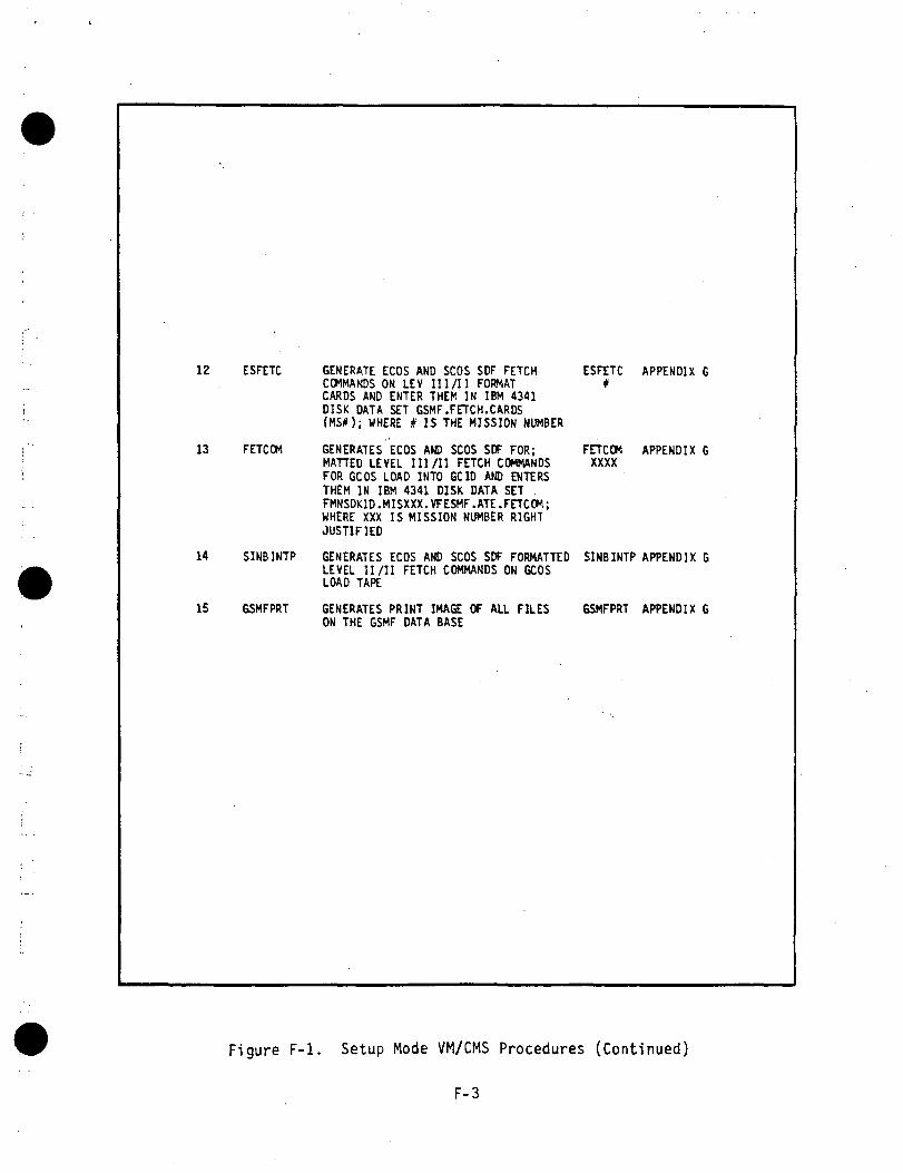
12 ESFETC GENERATE ECOS AND SCOS SDF FETCHCOMMANDS ON LEV III/I I FORMATCARDS AND ENTER THEM IN IBM 4341DISK DATA SET GSMF.FETCH.CARDS(MS#) ; WHERE # IS THE MISSION NUMBER
13 FETCOM GENERATES ECOS AND SCOS SDF FOR;MATTED LEVEL III/II FETCH COMMANDSFOR GCOS LOAD INTO GCID AND ENTERSTHEM IN IBM 4341 DISK DATA SET .FMNSDK1D.MISXXX.VFESMF.ATE.FETCOM;WHERE XXX IS MISSION NUMBER RIGHTJUSTIFIED
14 SINBINTP GENERATES ECOS AND SCOS SDF FORMATTEDLEVEL II/II FETCH COMMANDS ON GCOSLOAD TAPE
15 GSMFPRT GENERATES PRINT IMAGE OF ALL FILESON THE GSMF DATA BASE
ESFETC#
FETCOMXXXX
APPENDIX G
APPENDIX G
SINBINTP APPENDIX G
GSMFPRT APPENDIX G
Figure F-l. Setup Mode VM/CMS Procedures (Continued)
F-3

Figures F-2 and F-3 represent an example of the VM/CMS interactive con-
versation using steps 1, 2, 3 and 4 with all inputs underlined.
1.2 Generation of SWID Data File
The SWID data file contains definitions of all end-items not contained inthe ATE Spacelab Data Base (SLDB). Also contained in the SWID data file areSCOS and ECOS Stimuli SWID (not contained in the ATE SLDB) which affect ATEmeasurements. Initially this data file must be created manually as a VM/CMSfile. Figure F-4 illustrates this date file and its associated fields.
It must be noted that all SWIDs will be assigned a negative SWID numberto differentiate it from all defined end-items on the ATE SLDB.
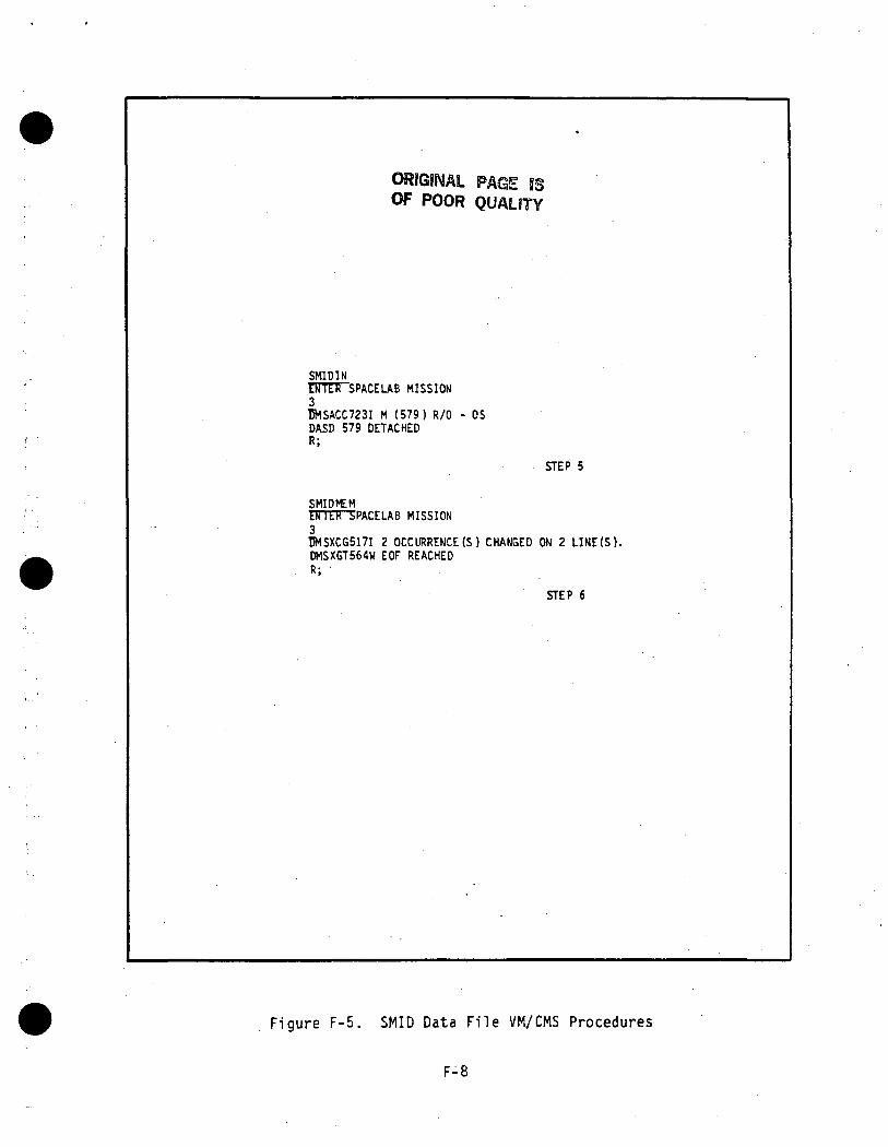
The procedures used to maintain this data file under VM/CMS are definedin steps 5 and 6 of Figure F-l which will selectively display the SWID datafile for a given Spacelab mission upon an IBM terminal for editing and thensave the new version on IBM disk for eventual GSMF data base addressing.Figure F-5 represents an example of the YM/CMS interactive conversation usingsteps 5 and 6 with all inputs underlined.
1.3 Run Documentation FileThe Run Documentation file will provide configuration management for the
GSMF data base. The components (Free Format) of this file are illustrated inFigure 3.2-4. Initially this file must be created manually as a VM/CMS file.The procedures used to maintain this file under VM/CMS are defined in steps 7and 8 of Figure F-l which will selectively display the run documentation filefor a given Spacelab mission upon a IBM terminal for editing and then save the
new version on IBM disk for eventual GSMF data base processing. Figure F-6represents an example of the VM/CMS interactive conversation using steps 7 and8 with all inputs underlined.
1.4 The SWID Initial Data FileThe SWID initial data file as defined in Section 3.2.2.6 and illustrated
in Figure F-7 shall be initially created for each Spacelab mission as a VM/CMSfile via manual inputs. This VM/CMS file shall contain initital values ininteger and floating point formats.
The procedures to maintain this data file under VM/CMS are defined in
steps 9 and 10 of Figure F-l which will selectively display the SWID initial
F-4

SWDPARTETTTER SPACELAB MISSION3ENTER ONE OF THE FOLLOWING ATE SUB TAB LI NAMES:DIGS CISC GOCL SOCD AIDA AIMS AOSA AISC DISDA DISM DIGDA DIGM GIDA GIMS DOSMDORM GOMS DIGS DOPANGISCCffSTCG517I 2 OCCURRENCE (S) CHANGED ON 2 LINE(S).DMSXCG517IDMSXCG517I
R;
OCCURRENCE (S) CHANGED ON 1 LINE(S).OCCURRENCE (S) CHANGED ON 1 LINE(S).
STEP 1
Figure F-2. SWID Relations VM/CMS Procedure
F-5

SPRSINMISSION
3_ENTER SUBTABLE NAMEGISCD"RTA~CC723I M (579) R/0 - OSDASD 579 DETACHEDR;
STEP 2
SPRSMEMEWTTSPACELAB MISSION3INTER SUBTABLE NAMEGISCDWCG517I 1 OCCURRENCE (S) CHANGED ON 1 L I N E ( S ) .DMSXCG517I 1 OCCURRENCE (S) CHANGED OIJ 1 L I N E ( S ) .DMSXGT564W EOF REACHEDR;SMIDMEMENTER SPACELAB MISSION3BMSXCG517I 2 OCCURRENCE (S) CHANGED ON 2 L I N E ( S ) .DMSXGT564W EOF REACHEDR;
STEP 3
swornENTER SPACELAB MISSION3DMSXCG517I 1 OCCURRENCE (S) CHANGED ON 1 L I N E ( S ) .DMSXCG517I 20 OCCURRENCE (S) CHANGED ON 20 L I N E ( S ) .R;
STEP 4
Figure F-3. SUID Pairs VM/CMS Procedures
F-6

SSN!
WARN LTCAUT LTFIRE LTMSTRALM LTCSDAUTOLPFIRE R(A)LPFIRE L(A)LPFIRE C(A)LPSYS CLSNGLPSYS CLSDLPUNUSEDUNUSEDSYS MAN TNEC*W TONEKLAXONSIRENFIRE R(B)LPFIRE L(B)LPFIRE C(B)LPUNUSEDWARN LAMP 1WARN LAMP 2WARN LAMP 3WARN LAMP' 4WARN LAMP 5WARN LAMP 6WARN LAMP 7 -WARN LAMP 8WARN LAMP 9WARN LAMP 10WARN LAMP 11WARN LAMP 12WARN LAMP 13 -WARN LAMP 14WARN LAMP 15WARN LAMP 16WARN LAMP 17SCOS MEASECOS MEASECOS MEASECOS MEASECOS MEASSCOS MEASSCOS MEASSCOS MEASSCOS CMDSCOS'CMDSCOS CMDSCOS CMDSCOS CMDSCOS CMDSCOS CMDSCOS CMDSCOS CMDCOLS 1 12
SMID/SMID123456789
10111213141516171819202122232425262728293031323334353637
5834445444544454405
568567575
16931694
1695
16961601
1605
16061608
161315 18
TYPE
23333222444444444
21 24
Figure F-4. SMID Data File Listing
F-7
ORIGINAL PAGE JSOF POOR QUALITY
SMIDINENTETTSPACELAB MISSION3TJMSACC723I M (579) R/0 - OSDASD 579 DETACHEDR;
STEP 5
SMIDMEMENTIR JJPACELAB MISSION3UMSXC6517I 2 OCCURRENCE (S) CHANGED ON 2 LINE(S).DMSXGT564W EOF REACHEDR;
STEP 6
Figure F-5. SMID Data File VM/CMS Procedures
F-8

RDOCINETTTTTTSPACELAB MISSION3BMSACC723I M (579) R/0 - OSDASD 579 DETACHEDR;
STEP 7
RDOCICMU J I L K SPACELAB MISSION3BMSXCG5171 2 OCCURRENCE (S) CHANGED ON 2 L I N E ( S ) .DMSXGT564W EOF REACHEDR;
STEP 8
Figure F-6. Run Documentation VM/CMS Procedures
F-9

SWID79007901790279037904790579067907790879097910791179127913791479157916791779187919792079217922792379317932793379347935793679377938793979407941794279437944794679477949795179617962872987308731879387948805
COLS. 4 8
DATA1
7.001
20.0. 7.0
01
20.030.020.0
0110.0110.0110.0
100000000000000
20.020.01.01.0
0000001
1.00011111
3.3511 15
Figure F-7. SWID Initial Data Listing
F-10

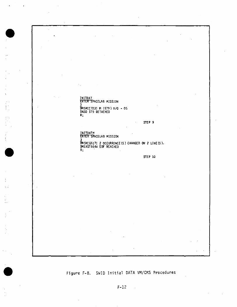
data file for a given Spacelab mission upon an IBM terminal for editing andthen save the new version on an IBM 4341 disk for eventual inclusion in theGSMF data base. Figure F-8 represents an example of the VM/CMS interactiveconversation using steps 9 and 10 with all inputs underlined.
When steps 1-10 have been exercised, all the preliminary data has beencreated and GSMF data base generation can begin. Step 11 in Figure F-l definesthe procedure and VM/CMS user inputs necessary for GSMF data base generation.
Figure F-9 reppresents an example of the VM/CMS interactive conversation usingstep 11 with all user inputs underlined. The user should note, as illustratedin Figure F-8, that in addition to the procedure "GSMFDB", additional inputsare required to satisfy magnetic tape allocation.Only when the response "TAPE 181 ATTACHED" is received, should the user enter"GSMFDB". This insures that a magnetic tape will be generated containing theGSMF data base.
F-ll
INITDATENTER SPACELAB MISSION3BMSACC723I M (579) R/0 - OSDASD 579 DETACHEDR;
STEP 9
INIJDAJMENTER SPACELAB MISSION3DMSXCG517I 2 OCCURRENCE (S) CHANGED ON 2 LINE(S).DMSXGT564W EOF REACHEDR;
STEP 10
Figure F-8, SWID Initial DATA VM/CMS Procedures
F-12

MOUNT SCRTCH 1B1MSG OP SCRTCH HftS VOL SER OF GSMFM*L** AND TITLE OF
GSMF DATA BASE MIS H LEVL (*M IS MISSION NUMBER. **L IS LEVEL)TAPE 1B1 ATTACHED6SMFDB
THIS CMS EXEC WILL GENERATE THE GSMF DATA BASE TAPE. THE FORMAT OFTHIS TAPE IS AS FOLLOWS:
CONTENTSECOS OFFSET FILESCOS OFFSET FILESWID/SMID MEAS OFFSET FILESTIMULI OFFSET FILEHARDWARE OFFSET FILESWID TYPE FILESWID INITIAL DATA FILERUN DOCUMENTATION FILE
FILE12345678
ENTER SPACELAB MISSION3I5ASD 507 DETACHEDDASD 507 DETACHEDDASD 508 DETACHEDDASD 507 DETACHEDDASD 507 DETACHEDDASD 508 DETACHEDDASD 507 DETACHEDDASD 508 DETACHEDDASD 507 DETACHEDSTARTING GENERATION OF ECOS OFFSET FILEGENERATION OF ECOS OFFSET FILE SUCCESSFUL
STARTING GENERATION OF SCOS OFFSET FILEGENERATION OF SCOS OFFSET FILE SUCCESSFUL
STARTING GENERATION OF SWID MEAS OFFSET FILEGENERATION OF SWID MEAS OFFSET FILE SUCCESSFUL
STATING GENERATION OF STIMULI OFFSET FILEGENERATION OF STIMULI OFFSET FILE SUCCESSFUL
STARTING GENERATION OF HARDWARE OFFSET FILEGENERATION OF HARDWARE OFFSET FILE SUCCESSFUL
STARTING GENERATION OF SWID TYPE FILEGENERATION OF SWID TYPE FILE SUCCESSFUL
STARTING GENERATION OF SWID INITIAL DATA FILEGENERATION OF SWID INITIAL DATA FILE SUCCESSFUL
STARTING GENERATION OF RUN DOCUMENTATION FILEGENERATION OF RUN DOCUMENTATION FILE SUCCESSFUL
GSMF DATA BASE TAPE GENERATION IS COMPLETER;
STEP 11
Figure F-9. GSMF Data Base Generation VM/CMS Procedure
F-13
APPENDIX G
MITRA SETUP MODE DATA

APPENDIX G
MITRA SETUP MODE DATA
1. SCOS/ECOS FETCH COMMANDS
In order to support GCOS monitoring of ECOS and SCOS telemetry data, a
set of SCOS/ECOS fetch commands must be loaded with the MITRA for eventual
download into the GCID. These fetch commands will be consistent with thoseutilized by the SCOS/ECOS simulation process in the Software Development
Facilities (SDF1 and SDF2) for a given Space!ab mission.
The procedures used to create these fetch commands under the IBM 4381
VM/CMS system are defined in steps 12-14 of Figure F-l. The output from these
steps will be a magnetic tape which must be loaded onto MITRA.
Figure G-l represents an example of the IBM VM/CMS interactive con-
versation using steps 12-14 with all user inputs underlined. The MITRA load
procedure is illustrated in Figure G-2.
2. DGNC DATA
In order to support DGNC data uplinks to SCOS and ECOS in the integratedmode, a tape containing DGNC data must be loaded onto the MITRA. Presentlythis data is being supplied by KSC, i.e., a tape is transmitted to Huntsville.This tape is then loaded onto the MITRA. The load procedure is illustrated inFigure G-3 where all user inputs are underlined.
G-l

ESFETCrRTOTSPACELAB MISSION3TJMSACC723I M (579) R/0 - OSOASD 579 DETACHEDDMSACC723I M (579) R/0 - OSDASD 579 DETACHEDDMSACC723I M (579) R/0 - OSDASD 579 DETACHEDDMSXCG517I 2 OCCURRENCE (S) CHANGED ON 2 LINE(S).DMSXGT564W EOF REACHEDR;
STEP 12
FETCOMENTER SPACELAB MISSION3UMSXCG517I 4 OCCURRENCE (S) CHANGED on 4 LINE(S).R;
STEP 13
SINBINTPEinnrnBRARY NAME OF MITRA JCL,MISSION,& CDT
EXAMPLE: JR01 MIS003 V1302JR01 MIS003 V1302
EOF REACHED
TOF:// VB8=VB8XXX ,// VB841IS003 ,// VB8=MIS003,// VB9=VB9XXX// VB9=V1302//REBLK.INPUT DD *EOF REACHEDfflN. "
ENTER 'X' TO XEDITJUST ENTER TO SKIP EDIT.
XPRESS ENTER TO SUBMIT
"NO" TO CANCEL.
XSYSGBIN EXEC COMPLETED.R;
STEP 14
Figure 6-1. ATE Fetch Command Generation VM/CMS Procedure
G-2

LOAD;/WP; ,MKT***** SYSTEM 'MMT .003' READY
30/MONT ?31/REIO ?*/EP/EXEC.SYSEP/.^^—~^^-^^~~m~*^^~~~*~~~
*/CAl/BATCH/NLN.» * / T K N = 0013
&/ BATCH OPERATING/GROUP « 02 CONNECTION
!AAS/B:SY,,M100,.M1.I .
!/iEOC.P2 /##MOUNT M100
TT7JOB/6,ID=DB8,COM=170.!!/JOB/6. ID=DB8,COM=170. ACTIVATED==/GROUP £ 03 CONNECTION : "$"$$/ME/ HUGH'S TEST FILES FOR SINaE BINARY FILE$$/ME/FETCOM.@2/*#MOUNT VN =DATA ON DM00P2/.H7D"304 END FHU2 LEV. 0$$/ME/COPY IDNAME FILE TO DATA FOR DATA REDUCTION$$/0304 END FMU2 LEV. 0==/GROUP & 03 DISCONNECTION==/IGNORE ABOVE : !0e0/ END OF BATCH"/GROUP « 02 DISCONNECTION
Figure G-2. MITRA Fetch Command Tape Load Procedure
G-3

LOAD;/WP;.MKT***** SYSTEM 'MMT .003' READY
KJ/MONT ?ei/REIO ?*/EP/EXEC.SYSEP/.
*/CAL /BATCH /NLN.**/TKN =0013
O*/ BATCH OPERATING/GROUP 402 CONNECTION : "!"
!/%AS/B:SY..mOO,.Ml.
/ O C .M100
TT7TOB/6 , ID=GNCS01 , COM=1 70 .!! /JOB/6, ID=GNCS01,COM=170. ACTIVATED==/GROUP 403 CONNECTION : "$"$$/ME/GNCS01.P2/*fMOUNT VN «=DGNC ON DM00e2/MO/DGNC.D^P5.$$/0304 END FMU2 LEV. 0== /GROUP 403 DISCONNECTION== /IGNORE ABOVE : !0(»?/ END OF BATCH« /GROUP 402 DISCONNECTION
Figure G-3. DGNC MITRA Tape Load Procedure
G-4

APPENDIX H
MITBA OPERATING PROCEDURES

APPENDIX H .
MITRA OPERATING PROCEDURES
Appendix H details the operating and execution instructions for loadingand starting the MITRA, starting GCOS, executing the GOAL LINK 3101 program,
stopping LINK, MITRA control of the MET, and executing the ITTS test software.
1. LOAD AND START THE MITRA
1) Verify the following MITRA panel switch settings:
a) Key to Mode 2 Manual
b) Mode to RD
c) H/AD to Off
d) MPC to SEL
e) Switches 13, 18, 19 UP; others down
f) Display to IND
2) Load the GCOS load deck and press RESET on the card reader.
3) On the MITRA panel, press INI and RUN.
4) On the MITRA teletype (A24).
Enter/MNP;MMTV1.*/CR.
On the MITRA panel change display switch to DATA
5) Upon completion of the card deck, terminal A14 will display "IS AWARM START REQUIRED?".
6) To disable the TLC 80 millisecond time out message, enter thefollowing patch on the teletype:
*/MO/*3252.«0:C711%/MO/&325F.&A:&C718
2. START GCOS
1) Start GCOS by entering (from terminal A14):
BGIN COLDY
H-l

2) During cold start, the followina undefined hardware addresses willbe displayed on terminal A17:
1840,1C40,2840,2C40,3840,3C40,4840,4C40
These stimuli are either undefined in the SL3 data base or theirbehavior is unknown.
3) Upon completion, terminal A14 will display 'STARTING CHECKOUT'.
3. RUN LINK CONFIGURATION 3101
1) Turn on the ECOS and SCOS links by entering the following from ter-minal A14:
P HACHAT TLCS ONCHAT TLCE ONCHAT TLMS ONCHAT TLME ON
2) From terminal A14, load a monitor table:
P SGLMOT SMT
Use terminal A15 to view the performance of LINK by
P SA
3) From terminal A14, begin LINK by entering:
PERF LINKP LINKRESUREPY 2 (Activate Space!ab Only)REPY X3101
Observe the programs that will be executed and enter:
REPY 1
4) Use terminal A13 to display the LINK program names by entering:
P LINK
5) If any programs require operator action the program name and "Q" willappear at the top of the page. To view the message, enter "P" follow-ed by the program name (example, P ABAN).
6) If any errors are encountered, set the measurement manually from thePerkin-Elmer Value Read/Write function. Then enter REPY 1 (RESTART)from terminal A14.
H-2

7) If any Manual intervention is required, the program name and "S" willappear at the top of the page. To view the message, enter "P" follow-ed by the program name (example P DACF). After performing the manualoperation, enter RESU.
8) NOTE: During execution of LINK 3101 the following undefined hardwareaddress message will appear: 19C5. The behavior for this stimulus isunknown.
9) The last LINK program EXCM, loads the experiment computer via the MMU.While it is executing, select DMfiN ELAV from terminal A14 and observethe IPL block count (7899) updated by the model:
10) Upon completion, observe the message "SL ACTIVATION PROGRAMCOMPLETED" on terminal A13.
4. EXECUTE THE DOWN PROGRAM
1) From terminal A14, enter:
P SGPERF DOWNP DOWNRESU
2) From terminal A15, select P SA to observe execution of DOWN.
3) Upon completion, observe "SL DEACTIVATION COMPLETE" on terminal A15.
4) Stop the MITRA by pressing the HALT button.
5. MITRA CONTROL OF THE MET
5.1 GMT and MET Transfer to the MIT
1) At the A15 enter the command GMT ON.
2) GMT will be displayed on A13. It should match the time displayed onthe GCID time code generator and GSMF terminals.
3) Enter the command MET ON at A14.
4) MET will be displayed on A13. The value should be constant becauseMET is initially stopped.
5.2 MITRA Control of MET
1) Enter the following commands at A14:
CD 7101CD 7223CD 7310CD 7458CD 7545
H-3

2) After entry of the above commands the MET displayed on A13 should be:
123 10 58 45
but should remain stopped.
3) Enter the command CD 77FO at the A15.
4) The MET displayed on A13 should begin incrementing.
5) Examine GMT and MET on the GSMF Performance Analysis terminal.
6. EXECUTING THE ITTS TEST PROGRAMS
6.1 SCCD Commands
OVERVIEW: This exercise sends SCCD commands to light or extinguish lampson the Operator Console.
6.1.1 Ver i fy Emergency Panel
1) Select to view emergency panel, function key 15.
2) From ITTS, issue Fire Right and Fire A (CD F040) . ,
3) Observe that Fire Right and Fire A lamps are lit.
4) From ITTS, reset Fire Right A (CD FOOD).
5) From ITTS, issue Fire Cabin B (CD F102).
6) Observe that Fire Cabin and Fire B lamps are lit .
7) From ITTS, reset Fire Cabin B (CD FIDO).
6.1.2 Ver i fy Caut ion and W a r n i n g Panel
1) Select to view Caution and Warn ing , function key 14.
2) From ITTS, set warning lamps 1-8 (CD FBFF).
3) Observe that warning lamps 1-8 are lit.
4) From ITTS, reset warn ing lamps 1-8 (CD FBOO).
5) Observe that warning lamps 1-8 are extinguished.
6) From ITTS, set caution lamps 1-8 (CD F8FF).
7) Observe that caution lamps 1-8 are lit.
8) From ITTS, reset caution lamps 1-8 (CD F800).
H-4

6.1.3 Verify Exception/Enable Panel
1) Select to view Exception/Enable Panel, function key 13.
2) From ITTS, set enable 1-8 (CD F2FF).
3) Observe that enable lamps 1-8 are lit.
4) From ITTS, reset enable 1-8 (CD F200).
5) Observe that enable lamps 1-8 are extinguished.
6) From ITTS, set exception 1-4 (CD F30F).
7) Observe that exception lamps 1-4 are lit.
8) From ITTS, reset exception 1-4 (CD F300).
9) Observe that exception lamps 1-4 are extinguished.
6.2 MSE Commands
OVERVIEW: This exercise sends MSE commands to affect Operator Console1 amps.
6.2.1 Control and Display Panel 1
1) Select C&D1 via shifted function 13.
2) From ITTS, issue APS-A ON (DO 1.1.03 ON).
3) Observe that lamp 1 is lit.
4) From ITTS, issue APS OFF (DO 1.1.07 OFF).
5) Observe that lamp 1 is extinguished.
6.2.2 Control and Display Panel 2
1) Select C&D2 via shifted function 14.
2) From ITTS, issue AVFAN1 Low (DO 1.3.36 ON).
3) Observe that lamp 1 is lit.
4) From ITTS, issue AVFAN12 OFF (DO 1.3.38 OFF).
5) Observe that lamp 1 is extinguished.
6.2.3 Control and Display Panel 3
1) Select C&D3 via shifted function 15.
2) From ITTS, issue RAU A ON (DO. 1.5.30 ON).
H-5
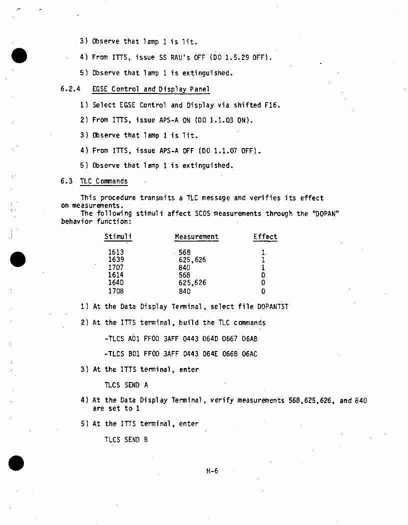
3) Observe that lamp 1 is lit.
4) From ITTS, issue SS RAU's OFF (DO 1.5.29 OFF).»
5) Observe that lamp 1 is extinguished.
6.2.4 EGSE Control and Display Panel
1) Select EGSE Control and Display via shifted F16.
2) From ITTS, issue APS-A ON (DO 1.1.03 ON).
3) Observe that lamp 1 is lit.
4) From ITTS, issue APS-A OFF (DO 1.1.07 OFF).
5) Observe that lamp 1 is extinguished.
6.3 TIC Commands
This procedure transmits a TLC message and verifies its effecton measurements.
The following stimuli affect SCOS measurements through the "DOPAN"behavior function:
Stimuli Measurement Effect
161316391707161416401708
568625,626840568625,626840
111000
1) At the Data Display Terminal, select file DOPANTST
2) At the ITTS terminal, build the TLC commands
-TLCS A01 FFOO 3AFF 0443 064D 0667 06AB
-TLCS B01 FFOO 3AFF 0443 064E 0668 06AC
3) At the ITTS terminal, enter
TLCS SEND A
4) At the Data Display Terminal, verify measurements 568,625,626, and 840are set to 1
5) At the ITTS terminal, enter
TLCS SEND B
H-6

6) At the Data Display terminal, verify measurements 568,625,626, and 840are set to 0.
6.4 Fetch Memory
This procedure provides a demonstration of fetch memory load and verify.
6.4.1 Fetch Memory Load
1) To prepare the MSE for the data transfer, enter the command MSE MODEAS at A14.
2) VDU1 should not display any errors.
3) Enter the command LP ER to disable the line printer.
4) Enter the command FM LOAD to start the load process.
5) Each MSE command executed will be displayed on A13.
6) To speed up the transfer, enter A13 ER to disable the command display.
7) Upon completion, the message FETCH MEMORY LOADED will be displayed onA13.
6.4.2 Fetch Memory Verify
1) To start the verify process enter FM CHECK at A14.
2) The MITRA will then read the fetch memory via the MSE and compare thedata with a load file. Errors will be displayed by the line printer.
3) The process takes about 2 minutes. At completion, A13 will indicatethe fetch memory has been checked.
H-7