grooming mower, 3-spindle - land pride · keep a first aid kit and fire extinguisher handy. keep...
TRANSCRIPT

© Copyright 2012 Printed
Read the Operator’s manual entirely. Whenyou see this symbol, the subsequentinstructions and warnings are serious - followwithout exception. Your life and the lives ofothers depend on it!
!
Table of Contents
Cover photo may show optional equipmentnot supplied with standard unit.
FD2560, FD2572, AT2560 & AT2572
Grooming Mower, 3-spindle
310-148MOperator’s Manual
8/08/12
10618
14326
Land Pride
Table of Contents
Important Safety Information . . . . . . . . . . .1Safety at All Times . . . . . . . . . . . . . . . . . . . . . . . . . 1Look For The Safety Alert Symbol . . . . . . . . . . . . . 1Safety Labels . . . . . . . . . . . . . . . . . . . . . . . . . . . . . 4
Introduction . . . . . . . . . . . . . . . . . . . . . . . .8Using This Manual . . . . . . . . . . . . . . . . . . . . . . . . . 8
Terminology . . . . . . . . . . . . . . . . . . . . . . . . . . . 8Definitions . . . . . . . . . . . . . . . . . . . . . . . . . . . . . 8
Owner Assistance . . . . . . . . . . . . . . . . . . . . . . . . . 8Serial Number Plate . . . . . . . . . . . . . . . . . . . . . 8Further Assistance . . . . . . . . . . . . . . . . . . . . . . 8
Section 1: Assembly & Set-up . . . . . . . . . .9General Description . . . . . . . . . . . . . . . . . . . . . . . . 9
Tools Required . . . . . . . . . . . . . . . . . . . . . . . . . 9Assembly Instructions . . . . . . . . . . . . . . . . . . . . . . 9
Upper Hitch Arms . . . . . . . . . . . . . . . . . . . . . . . 9Lower Hitch Lugs . . . . . . . . . . . . . . . . . . . . . . . 9Initial Hitch Arm Position . . . . . . . . . . . . . . . . . . 9Gauge Wheel Assembly . . . . . . . . . . . . . . . . . 10Grass Chute Assembly . . . . . . . . . . . . . . . . . . 10Final Inspection . . . . . . . . . . . . . . . . . . . . . . . . 10
Section 2: Operating Instructions . . . . . .11General Description . . . . . . . . . . . . . . . . . . . . . . . 11Pre-Start Instructions . . . . . . . . . . . . . . . . . . . . . . 11
Tractor Requirements . . . . . . . . . . . . . . . . . . . 11Tractor Hook-Up . . . . . . . . . . . . . . . . . . . . . . . 11
Driveline Installation . . . . . . . . . . . . . . . . . . . . . . . 11Checking Driveline Minimum Length . . . . . . . . 12
Operating Instructions . . . . . . . . . . . . . . . . . . . . . 13Transporting . . . . . . . . . . . . . . . . . . . . . . . . . . . . 13
Section 3: Adjustments . . . . . . . . . . . . . .14Mower Chute . . . . . . . . . . . . . . . . . . . . . . . . . . . . 14Floating & Front ToBack Hitch Adjustments . . . . . . . . . . . . . . . . . . . . 14Leveling The Mower . . . . . . . . . . . . . . . . . . . . . . 14
Four Gauge Wheels . . . . . . . . . . . . . . . . . . . . 14Cutting Height Adjustment . . . . . . . . . . . . . . . . . . 15Belt Tension . . . . . . . . . . . . . . . . . . . . . . . . . . . . . 15
Table of Contents
FD2560, FD2572, AT2560 & AT2572 Grooming Mower, 3-sp
© Copyright 2012 All rights Reserved
Land Pride provides this publication “as is” without warranty of any kind, either expressedPride assumes no responsibility for errors or omissions. Neither is any liability assumed forthe right to revise and improve its products as it sees fit. This publication describes the stat
Land Pride is a reg
All other brands and product names are trademarks
Printed in the United
Section 4: Maintenance and Lubrication 16General Maintenance . . . . . . . . . . . . . . . . . . . . . . 16
Blade Inspection . . . . . . . . . . . . . . . . . . . . . . . 16Blade Sharpening . . . . . . . . . . . . . . . . . . . . . . 16Blade Replacement . . . . . . . . . . . . . . . . . . . . . 17AIR TIRES (AIR PRESSURE): . . . . . . . . . . . .17V-Belt Installation . . . . . . . . . . . . . . . . . . . . . . 17Belt Tension . . . . . . . . . . . . . . . . . . . . . . . . . . 17
Storage . . . . . . . . . . . . . . . . . . . . . . . . . . . . . . . . 17Lubrication . . . . . . . . . . . . . . . . . . . . . . . . . . . . . . 18
Service Daily . . . . . . . . . . . . . . . . . . . . . . . . . . 18Service Every 50 Hours Of Operation: . . . . . .18PTO U-Joint . . . . . . . . . . . . . . . . . . . . . . . . . . . 18PTO Shaft . . . . . . . . . . . . . . . . . . . . . . . . . . . . 18Gearbox . . . . . . . . . . . . . . . . . . . . . . . . . . . . . 19Wheel Bushing (Martin) . . . . . . . . . . . . . . . . . . 19Wheel Bushing (Neilson) . . . . . . . . . . . . . . . . . 19Bearing in Blade Spindle Hubs . . . . . . . . . . . .20Wheel Support Bushings . . . . . . . . . . . . . . . . . 20
Section 5: Options . . . . . . . . . . . . . . . . . .21
Section 6: Specifications & Capacities . .22
Section 7: Troubleshooting . . . . . . . . . . .23
Section 8: Appendix . . . . . . . . . . . . . . . . .24Torque Values Chart . . . . . . . . . . . . . . . . . . . . . . 24Tire Inflation Chart . . . . . . . . . . . . . . . . . . . . . . . . 24Warranty . . . . . . . . . . . . . . . . . . . . . . . . . . . . . . . 25
indle 310-148M 8/08/12
or implied. While every precaution has been taken in the preparation of this manual, Landdamages resulting from the use of the information contained herein. Land Pride reserves
e of this product at the time of its publication, and may not reflect the product in the future.
istered trademark.
or registered trademarks of their respective holders.
States of America.

Important Safety Information
Land Pride Table of Contents▲
Important Safety Information
These are common practices that may or may not be applicable to the products described inthis manual.!Be Aware ofSignal WordsA Signal word designates a degree orlevel of hazard seriousness. Thesignal words are:
Indicates an imminently hazardoussituation which, if not avoided, willresult in death or serious injury. Thissignal word is limited to the mostextreme situations, typically formachine components that, forfunctional purposes, cannot beguarded.
! DANGER
Indicates a potentially hazardoussituation which, if not avoided, couldresult in death or serious injury, andincludes hazards that are exposedwhen guards are removed. It may alsobe used to alert against unsafepractices.
Indicates a potentially hazardoussituation which, if not avoided, mayresult in minor or moderate injury. Itmay also be used to alert againstunsafe practices.
! WARNING
! CAUTION
For Your Protection▲ Thoroughly read and understand
the “Safety Label” section, read allinstructions noted on them.
Shutdown and Storage▲ Lower machine to ground, put
tractor in park, turn off engine, andremove the key.
▲ Detach and store implements in aarea where children normally do
Safety at All TimesThoroughly read and understandthe instructions given in thismanual before operation. Refer tothe “Safety Label” section, readall instructions noted on them.Do not allow anyone to operatethis equipment who has not fullyread and comprehended thismanual and who has not beenproperly trained in the safeoperation of the equipment.
▲ Operator should be familiar withall functions of the unit.
▲ Operate implement from thedriver’s seat only.
▲ Make sure all guards and shieldsare in place and secured beforeoperating the implement.
▲ Do not leave tractor or implementunattended with engine running.
▲ Dismounting from a movingtractor could cause serious injuryor death.
▲ Do not stand between the tractorand implement during hitching.
▲ Keep hands, feet, and clothingaway from power-driven parts.
▲ Wear snug fitting clothing to avoidentanglement with moving parts.
▲ Watch out for wires, trees, etc.,when raising implement. Makesure all persons are clear ofworking area.
▲ Turning tractor too tight maycause implement to ride up onwheels. This could result in injuryor equipment damage.
8/08/12 FD2560, FD2572,
Look For The Safety Alert SymbolThe SAFETY ALERT SYMBOL indicates there is apotential hazard to personal safety involved and extrasafety precaution must be taken. When you see thissymbol, be alert and carefully read the message thatfollows it. In addition to design and configuration ofequipment, hazard control and accident preventionare dependent upon the awareness, concern,prudence and proper training of personnel involved inthe operation, transport, maintenance and storage ofequipment.
1 AT2560 & AT2572 Grooming Mower, 3-spindle 310-148M
not play. Secure implement byusing blocks and supports.
OFF
REMOVE
2
Important Safety Information
FD2560, FD2572, AT2560 & AT2572 Groom
Land PrideTable of Contents
Use SafetyLights and Devices▲ Slow moving tractors, self-
propelled equipment, and towedimplements can create a hazardwhen driven on public roads. Theyare difficult to see, especially atnight.
▲ Flashing warning lights and turnsignals are recommendedwhenever driving on public roads.Use lights and devices providedwith implement.
Use A Safety Chain▲ A safety chain will help control
drawn machinery should itseparate from the tractordrawbar.
▲ Use a chain with the strengthrating equal to or greater thanthe gross weight of the towedmachinery.
▲ Attach the chain to the tractordrawbar support or otherspecified anchor location. Allowonly enough slack in the chain topermit turning.
▲ Do not use safety chain fortowing.
These are common practices that may or may not be applicable to the products described inthis manual.
TransportMachinery Safely▲ Comply with state and local laws.▲ Maximum transport speed for
implement is 20 mph. DO NOTEXCEED. Never travel at a speedwhich does not allow adequatecontrol of steering and stopping.Some rough terrain require aslower speed.
▲ Sudden braking can cause atowed load to swerve and upset.Reduce speed if towed load is notequipped with brakes.
ing Mower, 3-spindle 310-148M
▲ Use the following maximumspeed - tow load weight ratios asa guideline:
▲ 20 mph when weight is less thanor equal to the weight of tractor.
▲ 10 mph when weight is doublethe weight of tractor.
▲ IMPORTANT: Do not tow a loadthat is more than double theweight of tractor.
Practice Safe Maintenance▲ Understand procedure before
doing work. Use proper tools andequipment, refer to Operator’sManual for additional information.
▲ Work in a clean dry area.▲ Lower the implement to the
ground, put tractor in park, turn offengine, and remove key beforepreforming maintenance.
▲ Allow implement to coolcompletely.
▲ Install all transport locks on raiseddrill before working underneath, referto the Operator’s Manual for quantityand location of transport locks.
▲ Do not grease or oil implementwhile it is in operation.
▲ Move the opener handle to the“ROAD” position and completeraising the openers to lock themup before working underneaththem.
▲ Disk edges are sharp. Be carefulwhen working in this area.
▲ Disconnect battery ground cable(-) before servicing or adjustingelectrical systems or beforewelding on implement.
▲ Inspect all parts. Make sure partsare in good condition & installedproperly.
▲ Remove buildup of grease, oil ordebris.
▲ Remove all tools and unused parsfrom implement before operation.
8/08/12

3
Important Safety Information
8/08/12 FD2560, FD2572, AT2560 & AT2572 Grooming Mower, 3-spindle 310-148M
Land Pride Table of Contents
Prepare for Emergencies▲ Be prepared if a fire starts.▲ Keep a first aid kit and fire
extinguisher handy.▲ Keep emergency numbers for
doctor, ambulance, hospital andfire department near phone.
911
WearProtective Equipment▲ Protective clothing and equipment
should be worn.▲ Wear clothing and equipment
appropriate for the job. Avoidloose fitting clothing.
▲ Prolonged exposure to loud noisecan cause hearing impairment orhearing loss. Wear suitablehearing protection such asearmuffs or earplugs.
▲ Operating equipment safelyrequires the full attention of theoperator. Avoid wearing radioheadphones while operatingmachinery.
These are common practices that may or may not be applicable to the products described inthis manual.
Keep RidersOff Machinery▲ Riders obstruct the operator’s
view, they could be struck byforeign objects or thrown from themachine.
▲ Never allow children to operateequipment.
Tire Safety▲ Tire changing can be dangerous
and should be preformed bytrained personnel using thecorrect tools and equipment.
▲ When inflating tires, use a clip-onchuck and extension hose longenough to allow you to stand toone side and NOT in front of orover the tire assembly. Use asafety cage if available.
▲ When removing and installingwheels, use wheel handlingequipment adequate for theweight involved.
Important Safety Information
Land PrideTable of Contents
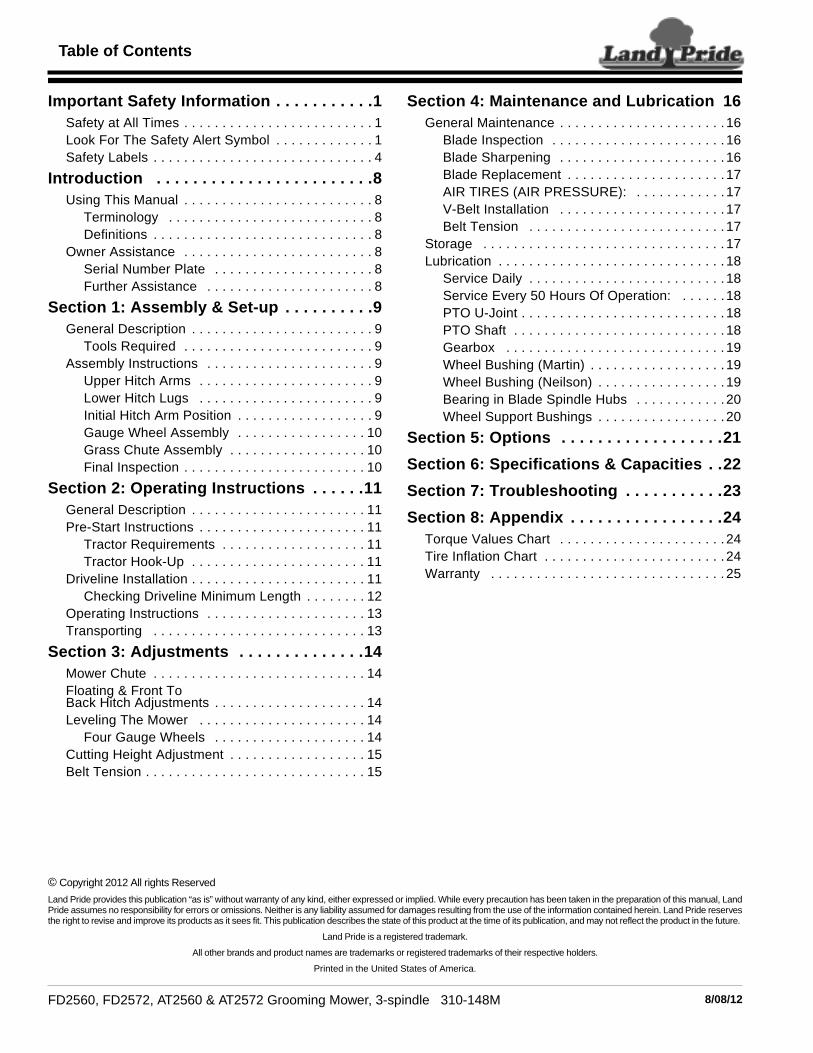
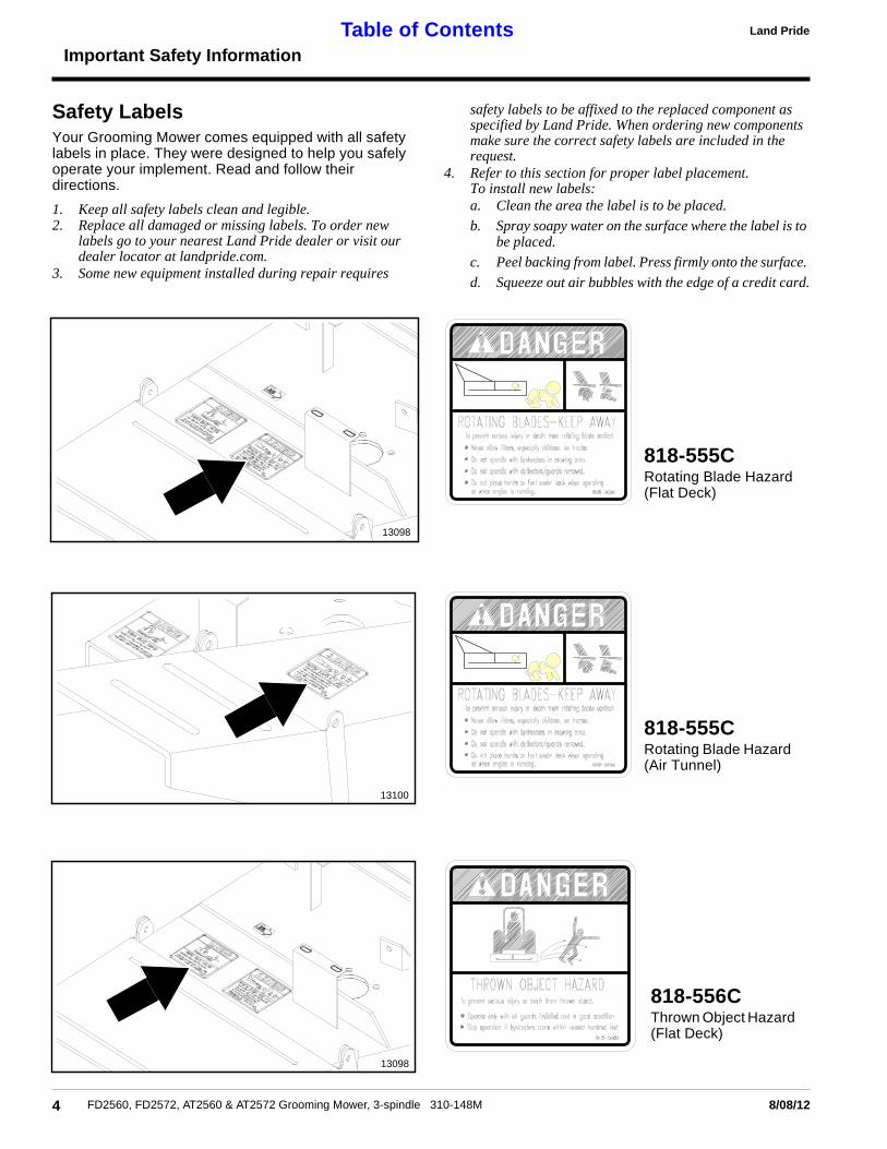
Safety LabelsYour Grooming Mower comes equipped with all safetylabels in place. They were designed to help you safelyoperate your implement. Read and follow theirdirections.
1. Keep all safety labels clean and legible.2. Replace all damaged or missing labels. To order new
labels go to your nearest Land Pride dealer or visit ourdealer locator at landpride.com.
3. Some new equipment installed during repair requires
4 FD2560, FD2572, AT2560 & AT2572 Grooming Mower, 3-spindle 3
13098
13100
13098
safety labels to be affixed to the replaced component asspecified by Land Pride. When ordering new componentsmake sure the correct safety labels are included in therequest.
4. Refer to this section for proper label placement.To install new labels:a. Clean the area the label is to be placed.
b. Spray soapy water on the surface where the label is tobe placed.
c. Peel backing from label. Press firmly onto the surface.
d. Squeeze out air bubbles with the edge of a credit card.
10-148M 8/08/12
818-556CThrown Object Hazard(Flat Deck)
818-555CRotating Blade Hazard(Flat Deck)
818-555CRotating Blade Hazard(Air Tunnel)

5
Important Safety Information
8/08/12 FD2560, FD2572, AT2560 & AT2572 Grooming Mower, 3-spindle 310-148M
Land Pride Table of Contents
13100
13099
13101
13099
818-556CThrown Object Hazard(Air Tunnel)
818-130COperate at 540 RPMPTO (Flat Deck)
818-130COperate at 540 RPMPTO (Air Tunnel)
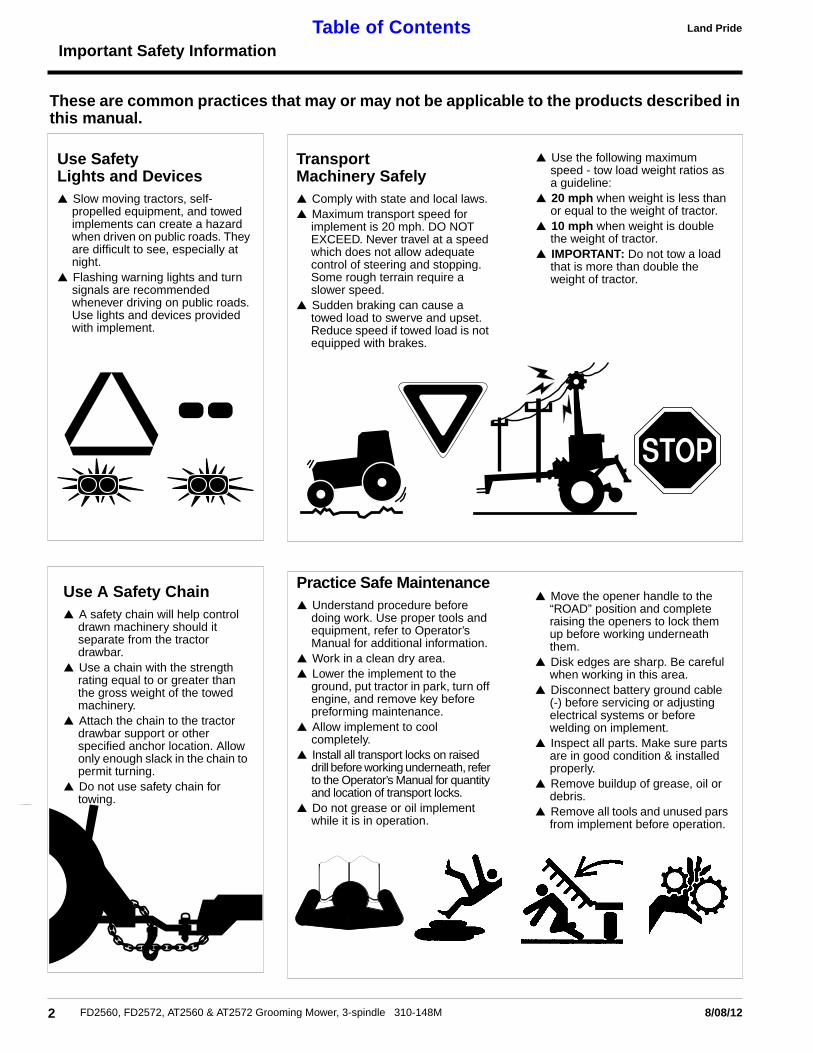
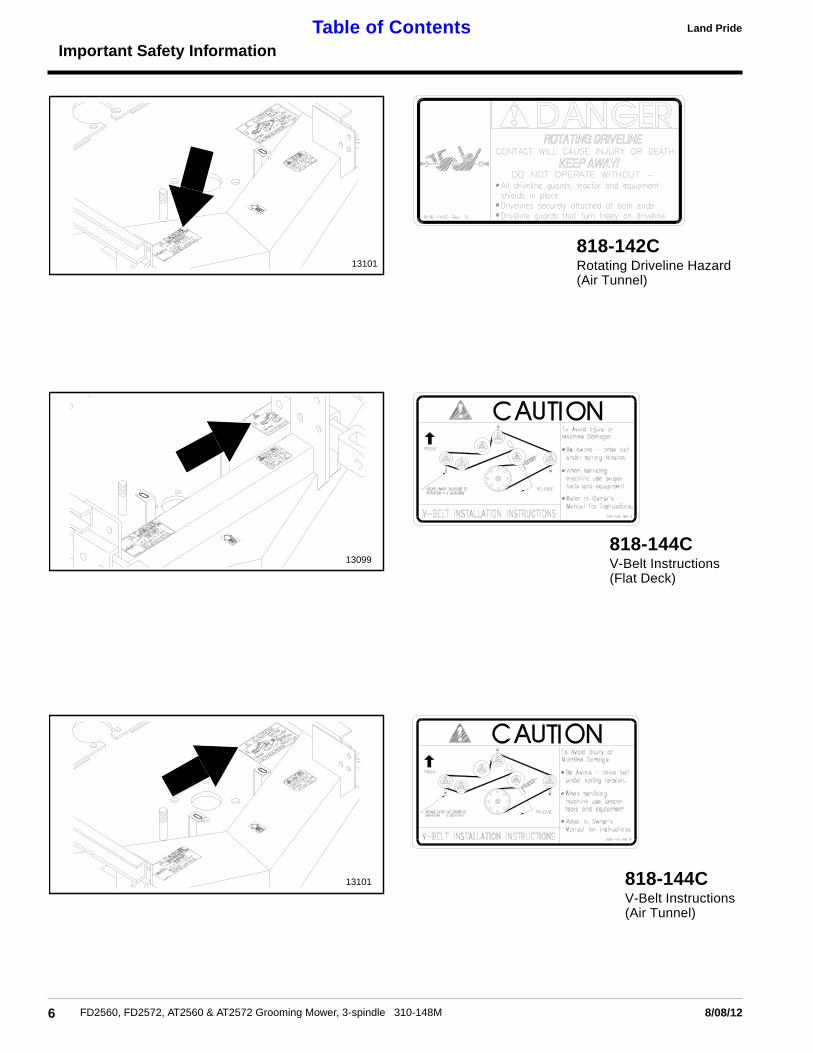
818-142CRotating Driveline Hazard(Flat Deck)
6
Important Safety Information
FD2560, FD2572, AT2560 & AT2572 Grooming Mower, 3-spindle 310-148M 8/08/12
Land PrideTable of Contents
13101
13099
13101
818-142CRotating Driveline Hazard(Air Tunnel)
818-144CV-Belt Instructions(Air Tunnel)
818-144CV-Belt Instructions(Flat Deck)

7
Important Safety Information
8/08/12 FD2560, FD2572, AT2560 & AT2572 Grooming Mower, 3-spindle 310-148M
Land Pride Table of Contents
13102
13102
ROTATING DRIVELINE
KEEP AWAY!
818-540CDanger Guard Missing
818-552CDanger Rotating Driveline
Introduction
Land PrideTable of Contents
IntroductionLand Pride welcomes you to the growing family of new
product owners.This Grooming Mower has been designed with care andbuilt by skilled workers using quality materials. Properassembly, maintenance and safe operating practices willhelp you get years of satisfactory use from the machine.
Using This Manual• This Operator’s Manual is designed to help familiarize
you with safety, assembly, operation, adjustments,troubleshooting, and maintenance. Read this manualand follow the recommendations to help ensure safeand efficient operation.
• The information contained within this manual wascurrent at the time of printing. Some parts may changeslightly to assure you of the best performance.
• To order a new Operator’s or Parts Manual contactyour authorized dealer. Manuals can also bedownloaded, free-of-charge from our website atwww.landpride.com or printed from the Land PrideService & Support Center by your dealer.
Terminology“Right” or “Left” as used in this manual is determined byfacing the direction the machine will operate while in useunless otherwise stated.
Definitions
Owner AssistanceThe Warranty Registration card should be filled out bythe dealer at the time of purchase. This information isnecessary to provide you with quality customer service.
If customer service or repair parts are required contact aLand Pride dealer. A dealer has trained personnel, repairparts and equipment needed to service the GroomingMower.
The parts on your Grooming Mower have been speciallydesigned and should only be replaced with genuine LandPride parts. Therefore, should your mower requirereplacement parts go to your Land Pride Dealer.
NOTE: A special point of information that theoperator must be aware of before continuing.
IMPORTANT: A special point of information relatedto its preceding topic. Land Pride’s intention is thatthis information should be read and noted beforecontinuing.
8 FD2560, FD2572, AT2560 & AT2572 Grooming Mower, 3-spindle 3
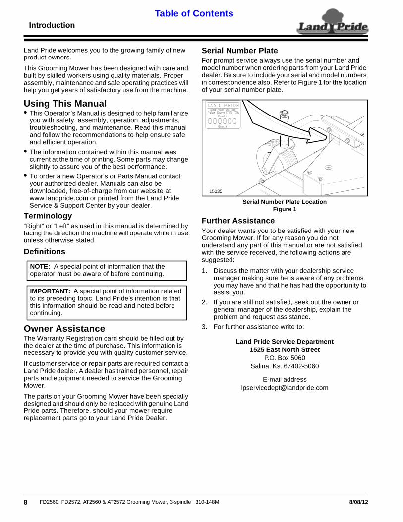
Serial Number PlateFor prompt service always use the serial number andmodel number when ordering parts from your Land Pridedealer. Be sure to include your serial and model numbersin correspondence also. Refer to Figure 1 for the locationof your serial number plate.
Serial Number Plate LocationFigure 1
Further AssistanceYour dealer wants you to be satisfied with your newGrooming Mower. If for any reason you do notunderstand any part of this manual or are not satisfiedwith the service received, the following actions aresuggested:
1. Discuss the matter with your dealership servicemanager making sure he is aware of any problemsyou may have and that he has had the opportunity toassist you.
2. If you are still not satisfied, seek out the owner orgeneral manager of the dealership, explain theproblem and request assistance.
3. For further assistance write to:
Land Pride Service Department1525 East North Street
P.O. Box 5060Salina, Ks. 67402-5060
E-mail [email protected]
15035
10-148M 8/08/12

Section 1: Assembly & Set-up
Land Pride Table of Contents
Section 1: Assembly & Set-up
General DescriptionThe 25 Series Grooming Mower is shipped crated andpartially assembled. Unloading and assembly of thisgrooming mower is the responsibility of the Land PrideDealer. The mower should be completely assembled,lubricated, and Adjusted for normal mowing operationsbefore delivery to the customer.Tools Required• Sufficient Lifting device (e.g., fork lift, hoist, tractor) see
“Specification Chart” for unit weight.
• Support Stands
• Regular Hand Tools
• Grease Gun
! CAUTIONAlways wear personal protection devices such as eye, ear, andfeet protectors during assembly operations.
Assembly InstructionsUsing a safe lifting device, set the crate on safesupporting stands. Remove crate. Remove loosecomponents - gauge wheels, gauge wheel arms andmiscellaneous hardware from the top of deck. Arrangeparts for easy identification.
Upper Hitch ArmsRefer to Figure 1-2:1. Loosen 5/8" x 1 3/4" long bolts (#1) and swing upper
hitch (#2) up to a vertical position.
2. Remove 5/8" x 5 1/2" long bolt (#3) and install upperhitch brace (#4), upper pivoting hitch (#5), and hitchspacer (#6) with 5/8" x 5 1/2" long bolt (#3).
3. Refer to Figure 1-4, for initial bolting location of upperhitch brace (#4).
Upper Hitch Arms AssemblyFigure 1-2
13542
8/08/12 FD2560, FD2
Lower Hitch LugsRefer to Figure 1-3The Hitch Lug (#1) is installed from the factory in theinward most position on the mower channel (#2).
1. Remove hair pin (#4). Remove pivot pin (#3)
2. Slide hitch lugs (#1) into the initial position as shownin Figure 1-4.
Lower Hitch LugsFigure 1-3
Initial Hitch Arm PositionRefer to Figure 1-41. Bolt the upper hitch arms and lower hitch lugs on the
mower to the positions shown
2. Tighten hardware to listed torque values.
Initial Hitch Arm PositionFigure 1-4
13543
11915
9572, AT2560 & AT2572 Grooming Mower, 3-spindle 310-148M

Section 1: Assembly & Set-up
Land PrideTable of Contents
Gauge Wheel AssemblyRefer to Figure 1-5:1. The rear gauge wheel arms (#1) are bolted to the
frame backwards from factory. Remove the 3/8" x 3"long bolt (#2), hardware and gauge wheel arm (#1).
2. Bolt the rear gauge wheel arms (#1) to the mountingchannels on the mower frame using 3/8" x 3" longbolt (#2) and hardware shown.
3. Insert the 1" diameter shaft of the gauge wheel yoke(#3) into the bushings on the gauge wheel arm (#1),noting the amount of spacers (#4) added to top orbottom depending on cutting height {refer to Section3 “Cutting Height Adjustments” on Page 15}.
4. Secure shaft to wheel arm with 1/4" lock pin (#5). Besure all the spacers are arranged the same on eachwheel assembly. Tighten all hardware to valueslisted in the “Torque Values Chart” in the appendix.
Gauge Wheel AssemblyFigure 1-5
13577
10 FD2560, FD2572, AT2560 & AT2572 Grooming Mower, 3-spindle 3
Grass Chute AssemblyRefer to Figure 1-5:1. Loosen upper pivot bolt (#1) and remove lower
thumb screw (#2).
Hinge chute down and install thumb screw (#2) and flatwasher(#3). When set at position desired, tighten downupper pivot bolt (#1) and lock nut (#4). Do not tightencompletely. Allow chute to hinge. Lock down lowerthumb screw (#2) with flat washer (#3).
2.
Grass Chute AssemblyFigure 1-6
Final InspectionAfter completing the “Dealer Assembly and Setup”section, fill out the “Warranty Registration Form &Inspection Report” in this manual.
13544
10-148M 8/08/12

Section 2: Operating Instructions
Land Pride Table of Contents
Section 2: Operating Instructions
General DescriptionThe operator is responsible for the safe use of thismachine. Read and understand the safety section beforecontinuing.This section covers the procedures needed to operatethis machine. Properly read and understand this sectionbefore operating.
Pre-Start InstructionsTractor RequirementsThis mower is designed with a 3-Point category I hitch.Horse power rating of the tractor should not exceed 30 PTOhorse power on 60 inch units and 35 PTO horse power on72 inch units. PTO Speed of tractor should be 540 RPM.
Tractor Hook-Up1. Be certain that the tractor draw bar will not interfere.
Move draw bar ahead or remove if required. Draw barshould also be checked for clearance when unit isbeing raised for the first time.
2. Align lower link arms of tractor to hitch lugs onmower. Insert lower hitch pins into lower ball swivelsand attach lynch pins.
3. Referring to Figure 2-1, attach tractor top link toupper floating hitch on mower with pin supplied.
4. Adjust the tractor top link in or out to place the upperhitch pin vertically above the lower hitch pins asshown in Figure 2-2, to allow mower flotation.
Driveline InstallationAn additional driveline may be required if the mower is tobe used on more than one tractor especially if a quickhitch is used.
! CAUTIONDo not use a PTO adaptor with a quick hitch. A PTO adapterwill increase strain on the tractor’s PTO shaft resulting inpossible damage the shaft and driveline.
! WARNINGDamaged drivelines can cause serious injury or death.
NOTE: In order to maintain steering control, ballastmay have to be added to your tractor. To determinewhether or not to add ballast, refer to your tractoroperator’s manual for weight requirements and to the“Specifications and Capacities” chart for the weightof the unit.
NOTE: The initial position of the Upper Hitch Armsand the Lower Hitch Lugs should be in the backposition. If there is a clearance problem refer to the“Adjustment Section” under “Floating & Front ToBack Hitch Adjustments” page 14.
8/08/12 FD2560, FD2
Front Position Hitch AdjustmentFigure 2-1
Back Position Floating Hitch AdjustmentFigure 2-2
! CAUTIONTractor PTO shield and all Grooming Mower guards must bein place at all times during operation!
! WARNINGDamaged drivelines can cause serious injury or death.
! CAUTIONAlways engage parking brake, shut off tractor and remove keybefore dismounting from tractor.
11915
11572, AT2560 & AT2572 Grooming Mower, 3-spindle 310-148M

Section 2: Operating Instructions
Land PrideTable of Contents
Maximum PTO driveline Movement During OperationFigure 2-3
Shortening the PTO ShaftsFigure 2-4
Checking Driveline Minimum LengthRefer to Figure 2-4:1. Start tractor and slowly engage 3-point to move
lower arms until the gearbox shaft is approximatelylevel with tractor's PTO shaft.
2. Slide inner yoke of the driveline over the gearboxshaft and secure with locking collar.
3. Slide outer yoke of driveline over the tractor PTOshaft and secure with locking collar. Skip to step 5 onpage 12 if driveline fits between tractor and gearbox.
IMPORTANT: Some tractors are equipped withmulti-speed PTO ranges. Be certain your tractor ‘sPTO is set for 540 rpm.
IMPORTANT: Avoid premature drivelinebreakdown. A driveline that is operating must notexceed an angle of 25 degrees up or down whileoperating the 3-point lift. See Figure 2-3 below.
13800
IMPORTANT: Always check driveline minimumlength during initial setup, when connecting to adifferent tractor and when alternating between usinga quick hitch and a standard 3-point hitch. More thanone driveline may be required to fit all applications.
IMPORTANT: It is necessary to aligning the tractor’sPTO shaft level with the gearbox shaft whenchecking driveline minimum length. Too long adriveline can damage tractor, gearbox and driveline.
22009
12 FD2560, FD2572, AT2560 & AT2572 Grooming Mower, 3-spindle 3
4. The driveline will require shortening if it is too long tofit between tractor and gearbox. Shorten driveline asfollows:
a. Raise or lower 3-point lower arms until gearboxand tractor PTO shafts are approximately levelwith each other. Securely block mower frame inthis position.
b. Set tractor in park, shut tractor engine off, set parkbrake and remove switch key.
c. Pull driveline apart into two sections as shown inFigure 2-4. Attach outer driveline universal joint tothe tractor PTO shaft. Attach inner drivelineuniversal joint to the gearbox shaft. Pull on eachdriveline section to be sure universal joints aresecured to the shafts.
d. Hold driveline sections parallel to each other todetermine if they are too long. The inner and outershields on each section should end approximately1" short of reaching the universal joint shield onthe adjacent section (see “B” dimension). If theyare too long, measure 1" (“B” dimension) backfrom the universal joint shield and make a mark atthis location on the inner and outer drivelineshields.
e. Cut off inner shield at mark (“X” dimension). Cutsame amount off inner shaft (“X1” dimension).Repeat cut off procedure (“Y” & “Y1” dimensions)to cut outer driveline half.
f. Remove all burrs and cuttings.
5. Apply multi-purpose grease to the inside of the outerdriveline shaft and reassemble the two shafts.
6. Attach inner driveline yoke to the gearbox shaft.
7. Attach outer driveline yoke to the tractor's PTO shaft.
8. The driveline should now be moved back and forth toinsure that both ends are secured to the tractor andgearbox PTO shafts. Reattach any end that is loose.
9. Hook one of the driveline safety chains in a hole onthe outer driveline yoke shield and the opposite endto the tractor to restrict outer shield rotation.
10. Hook the second driveline safety chain in a hole onthe inner driveline yoke shield and the opposite endto the mower to restrict inner shield rotation.
11. Start tractor and raise the Grooming Mower justenough to remove blocks used to support the mowerframe in step 4a above.
12. Slowly engage the tractor’s hydraulic 3-point to lowerthe mower. Check for sufficient drawbar clearance.Move drawbar ahead, aside or remove if required.
IMPORTANT: Two small chains are supplied withthe driveline. These chains must be attached toouter and inner driveline yoke shields and to thecutter deck and tractor to restrict driveline shieldsfrom rotating.
10-148M 8/08/12
Section 2: Operating Instructions
Land Pride Table of Contents
Operating Instructions
1. Clear the area to be mowed of objects and debristhat might be picked up and thrown by the mowerblades.
2. Grass is best cut when it is dry. Mowing wet grasscan cause plugging resulting in grass clumps behindthe mower.
3. Grass should be mowed frequently as shorterclippings deteriorate faster.
4. If mowing extremely tall grass, it is best to raisecutting height and mow the area, then lower cuttingheight and mow a second time at the desired height.
5. Lower mower to ground. Set tractor throttle atapproximately 1/4 open. Engage PTO to start bladesrotating.
6. Operate only with 540rpm PTO tractor.
7. At first, begin mowing at a slow forward speed andshift up until the desired speed is achieved -maintaining 540 PTO rpm.
8. Mower blades will cut better at a faster rotor speedthan at reduced throttle.
9. After mowing the first 50 feet, stop and check to seethat the mower is adjusted properly.
10. Do not make sharp turns or attempt to back up whilemower is on the ground.
11. Do not engage PTO with mower in the fully raisedposition. Do not engage PTO at full throttle.
12. After mowing disconnect tractor PTO and followtransporting procedures.
! CAUTIONWhen mowing in sandy soil areas, wear may occur to yourmower blades caused from sand erosion. Frequent inspectionshould be made and blades replaced if damaged
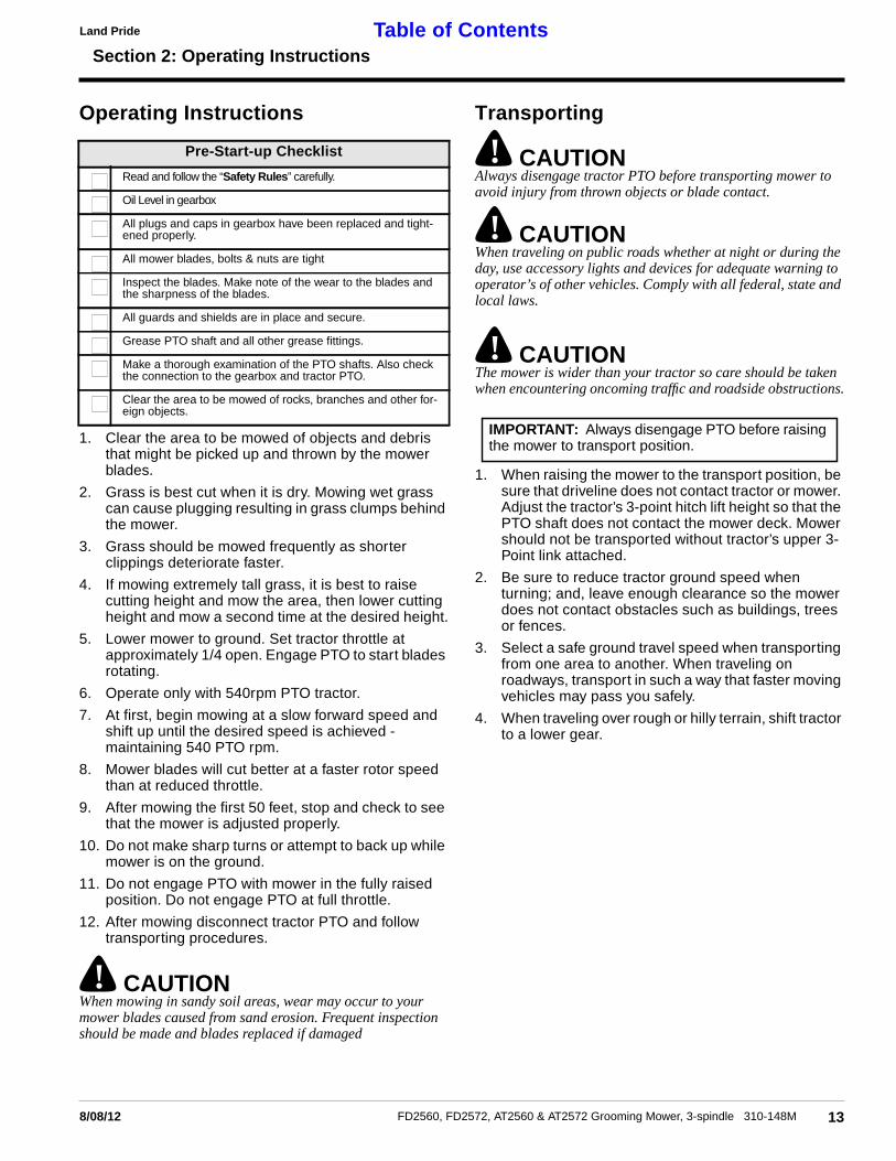
Pre-Start-up Checklist
Read and follow the “Safety Rules” carefully.
Oil Level in gearbox
All plugs and caps in gearbox have been replaced and tight-ened properly.
All mower blades, bolts & nuts are tight
Inspect the blades. Make note of the wear to the blades andthe sharpness of the blades.
All guards and shields are in place and secure.
Grease PTO shaft and all other grease fittings.
Make a thorough examination of the PTO shafts. Also checkthe connection to the gearbox and tractor PTO.
Clear the area to be mowed of rocks, branches and other for-eign objects.
8/08/12 FD2560, FD2
Transporting
! CAUTIONAlways disengage tractor PTO before transporting mower toavoid injury from thrown objects or blade contact.
! CAUTIONWhen traveling on public roads whether at night or during theday, use accessory lights and devices for adequate warning tooperator’s of other vehicles. Comply with all federal, state andlocal laws.
! CAUTIONThe mower is wider than your tractor so care should be takenwhen encountering oncoming traffic and roadside obstructions.
1. When raising the mower to the transport position, besure that driveline does not contact tractor or mower.Adjust the tractor’s 3-point hitch lift height so that thePTO shaft does not contact the mower deck. Mowershould not be transported without tractor’s upper 3-Point link attached.
2. Be sure to reduce tractor ground speed whenturning; and, leave enough clearance so the mowerdoes not contact obstacles such as buildings, treesor fences.
3. Select a safe ground travel speed when transportingfrom one area to another. When traveling onroadways, transport in such a way that faster movingvehicles may pass you safely.
4. When traveling over rough or hilly terrain, shift tractorto a lower gear.
IMPORTANT: Always disengage PTO before raisingthe mower to transport position.
13572, AT2560 & AT2572 Grooming Mower, 3-spindle 310-148M

Section 3: Adjustments
Land PrideTable of Contents
Section 3: Adjustments
! CAUTIONDisengage PTO, engage parking brake, shut off tractor, andremove key before making any adjustments!
Mower ChuteThis mower is equipped with an adjustable grassdischarge chute. Adjustments can be made by looseningthe bolts on the front and rear of mower chute. With themower chute in the raised operating position, grass isexpelled away from the mower for a more evendistribution of grass clippings. Lowering the mower chutewill decrease the distance the grass is discharged fromthe mower.
! DANGERDO NOT in any condition operate mower with chute removed
Floating & Front ToBack Hitch AdjustmentsThe 3-point hitch system on this mower has beendesigned for front to back flotation when mowing onuneven terrain. The lower 3-point hitch blocks also areadjustable from front to back for additional field float andtractor clearance. The lower hitch blocks and top link rearbraces can be adjusted front to back as shown in Figure3-1 and Figure 3-2, Middle Position Floating HitchAdjustment, in lFigure 3-2. Deviation from the 3 settingwill limit field float.
Front Position Hitch AdjustmentFigure 3-1
NOTE: Positioning the Upper Hitch Arms and LowerHitch Lugs to the back setting shortens overall tractor/mower length allowing tighter turns and increasinglifting power.
14 FD2560, FD2572, AT2560 & AT2572 Grooming Mower, 3-spindle 3
Middle Position Floating Hitch AdjustmentFigure 3-2
Back Position Hitch AdjustmentFigure 3-3
Leveling The MowerFour Gauge Wheels
1. Set lower hitches and upper floating hitch, as shownin Figure 3-1, Figure 3-2, or Figure 3-3.
2. Make sure PTO is disengaged and start tractor.
3. Raise mower, watching that tractor draw bar (if notremoved) does not interfere with mower.
4. Slowly lower the mower until gauge wheels touch theground and the lower mower 3-point hitch bars areparallel to the ground in floating position. Set thetractor’s 3-point stop.
11023
11917
NOTE: Tractor and mower should be on level ground.
10-148M 8/08/12

Section 3: Adjustments
Land Pride Table of Contents
5. Set the parking brake and turn off tractor. Removekey from ignition.
6. Adjust the tractor top link in or out to place the upperhitch pin vertically above the lower hitch pin asshown in Figure 3-1, Figure 3-2, or Figure 3-3, toallow mower flotation.
7. Rotate blades in line with direction of travel.
8. Measure the clearance from the cutting edge to theground at front and rear of the blade. Thismeasurement should be equal or have the blade atthe front of the mower not more than 1/2" lower thanthe blade at the rear of the mower.
Cutting Height Adjustment1. Using the tractor, raise the mower off the ground and
support under it with secure blocking so not to let themower drift down during maintenance.
2. Holding wheel and yoke assembly up, remove quick-lock pin from top of gauge wheel spindle. Position fulllength spacers and half spacer as required. Allspacers on top of spindle tube allows forapproximately 1" cutting height. Adjustments rangefrom 1" to a maximum of 5 1/2" in 1/2" increments.Refer to “Leveling The Mower” page 14.
! CAUTIONEngage parking brake, shut off tractor, remove key anddisengage PTO before making any height adjustments!
Belt TensionRefer to Figure 3-4:
! CAUTIONBelt drive system under spring tension; use care to avoid bodilyharm!
1. To check tension apply force at arrow A. With atension tester and deflect the belt 1/4". The forcerequired to get this deflection should range from 7 to10 lbs.
2. To adjust belt tension, adjust eyebolt (#1), asnecessary. This adjustment will increase or decreasethe tension on spring (#2).
3. Excessive tension on the belt may lead to prematurefailure of belt and drive components. Excessivetension on the belt may also lead to a safety hazardto the operator or bystanders. Not enough tension onthe belt may lead to premature failure of the belt dueto excessive slipping.
4. Excessive tension on the belt may lead to prematurefailure of belt and drive components. Excessivetension on the belt may also lead to a safety hazardto the operator or bystanders.
8/08/12 FD2560, FD2
Belt TensionFigure 3-4
12732
15572, AT2560 & AT2572 Grooming Mower, 3-spindle 310-148M

Section 4: Maintenance and Lubrication
Land PrideTable of Contents
Proper servicing and adjustment is the key to the long lifeSection 4: Maintenance and Lubrication
of any implement. With careful and systematicinspection, you can avoid costly maintenance, time andrepair.
After using your Grooming Mower for several hours,check all bolts to be sure they are tight.
Replace any worn, damaged or illegible safety labels byobtaining new labels from your Land Pride Dealer.
! CAUTIONFor Safety reasons, each maintenance operation must beperformed with the tractor’s PTO disengaged, the mowerlowered completely, tractor engine shut off and ignition keyremoved.
General MaintenanceBlade InspectionRefer to Figure 4-1:
! DANGERBent, Deformed or Split Blades: Should be removed from unitand discarded. DO NOT attempt to straighten for reuse.
! WARNINGDO NOT attempt to modify blade, such as hard surfacing, heator cold treating and/or by any other method.
! DANGERDO NOT try to straighten a blade that is bent. Never weld abroken or cracked blade. ALWAYS replace with a new LandPride blade to assure safety.
NOTE: Blade Wear: As blades wear and aresharpened, the blade performance will be reduced.
16 FD2560, FD2572, AT2560 & AT2572 Grooming Mower, 3-spindle 3
Inspection of Blades & SharpeningFigure 4-1
Blade Sharpening
! CAUTIONALWAYS wear eye protection and gloves when sharpening ablade.
1. If the blade cutting edge is dull or nicked, it should bereplaced or sharpened. Remove blades for replacingor sharpening by grasping the end of the blade usinga rag or a thick, padded glove, while loosening andremoving the bolt/bolts that mount the blade.
2. Clean blade, blade washer and mounting surface ofall debris before replacing or sharpening.
3. Grind cutting edge at the same bevel as the original.See Figure 4-2. Sharpen only the top of the cuttingedge to maintain sharpness.
Blade SharpeningFigure 4-2
IMPORTANT: Always install blade with the cuttingedge facing direction of rotation.
IMPORTANT: Replace blades with Land Prideblades only.
NOTE: Care should be taken in order not to removeany more material than necessary to sharpen blade.
19327
10-148M 8/08/12

Section 4: Maintenance and Lubrication
Land Pride Table of Contents
4. Check blade balance by positioning the bladehorizontally on a nail or shaft through the center hole.See Figure 4-3. If either end of the blade rotatesdownward, grind (remove) metal on that end until theblade will balance. The blade is properly balancedwhen neither end drops. Balance of a blade isgenerally maintained by removing an equal amountof material from each end of the blade whensharpening.
Blade BalancingFigure 4-3
Blade Replacement
1. Remove cap screw and blade washer from blade tobe replaced. Remove blade.
2. Install blade washer into center hole on blade.
3. Replace cap screw. Tighten bolts to proper torque,see the “Torque Values Chart” section on page 24.
AIR TIRES (AIR PRESSURE):Tire Sealant: Heavy Duty tire sealant has been added inAir tires to help reduce air loss from punchers due tonails/thorns etc....
V-Belt Installation1. Remove right hand, left hand and center belt covers.
V-Belt Installation, Routing & Rotation DecalFigure 4-4
19046 NAIL OR SHAFT
HORIZONTAL
IMPORTANT: Always install blade with cutting edgefacing direction of blade spindle rotation and wingtips pointing up towards bottom of deck.
IMPORTANT: Replace blades with Land Prideblades only.
NOTE: Under inflated tires can roll off of rim.Maintaining air pressure within 5 PSI of maximum tirepressure reduces the risk of tires rolling off of rim.
8/08/12 FD2560, FD
2. Move belt take-up handle in a clockwise direction torelieve tension on belt.
3. With tension relieved from belt remove old belt frompulleys.
4. Install new belt referring to the figure below (alsorefer to the decal on top of mower deck). Be sure beltis positioned in all the pulley grooves. Release belttake-up handle to apply tension to new belt.
5. Reinstall all belt covers and secure in place withhardware.
Belt Tension
! CAUTIONBelt drive system under spring tension; use care to avoid bodilyharm!
1. Belt tension should be checked after approximately20 hours of operation on a new belt.
2. Not enough tension on the belt may lead topremature failure of the belt due to excessiveslipping of the belt.
Refer to “Belt Tension” on page 15 for properadjustment of belt tension.
! WARNINGExcessive tension on the belt may lead to premature failure ofbelt and drive components. Excessive tension on the belt mayalso lead to a safety hazard to the operator or bystanders.
StorageAt the end of the working season or when the mower willnot be used for a long period, it is good practice to cleanoff any dirt or grease that may have accumulated on themower and any of the moving parts. It may be necessaryto scrape off compacted dirt from the bottom of the deck,then use a garden hose to thoroughly clean the surface.
1. Clean the mower as necessary. Be sure that themower is completely cleaned before storing.
2. Check the blades for wear and replace if necessary,see “Maintenance” section on page 16.
3. Inspect the mower for loose, damaged or worn partsand adjust or replace if needed.
4. Lubricate as noted in the “Lubrication” section onpage 18.
5. Remove mower drive belt from one pulley to releasedrive belt tension.
6. Remove belt guards, thoroughly clean the top andbottom of the mower frame.
7. Repaint parts where paint is worn or scratched toprevent rust. Aerosol beige touch-up paint isavailable from your dealer. Order Land Pride part#821-011C.
8. Store mower in a clean, dry place for longer mowerlife.
172572, AT2560 & AT2572 Grooming Mower, 3-spindle 310-148M

Section 4: Maintenance and Lubrication
Land PrideTable of Contents
Lubrication
! CAUTIONFor Safety reasons, each lubrication operation must beperformed with the tractor’s PTO disengaged, the mowerlowered completely, tractor engine shut off and ignition keyremoved.
Service Daily1. Grease the PTO u-joints.
2. Wheel support bushings.
3. Wheel bushing.
4. Bearing in blade spindle hubs.
18 FD2560, FD2572, AT2560 & AT2572 Grooming Mower, 3-spindle 3
Multi-purposespray lube
Multi-pugrease l
LubricationLegend
12559
12559
Service Every 50 Hours Of Operation:1. With the mower on level ground, check the oil level in
the gearbox by removing the plug in the side of thebox. The oil should reach the plug hole. If oil level islow, remove the top plug in the gearcase and fill withSAE 90 oil until oil flows from side port of thegearbox. Reinstall plugs and retighten.
2. Disconnect PTO shaft from the tractor and slideapart. Clean and coat the inner tube of the PTO shaftwith a light film of grease and then reassemble.
IMPORTANT: Do not overfill! Should your gearboxrequire repair, take it to your Land Pride dealer.
50rposeube
Intervals in hoursat which lubricationis required
Multi-purposeoil lube
8Hours
PTO U-JointCoat PTO u-joint with grease every 8 hours of operation
Type of Lubrication: Multipurpose
Quantity = Coat Generously
20Hours
PTO ShaftDisconnect PTO shaft from the tractor and slide apart.Clean and coat the inner tube of the PTO shaft with alight film of grease and then reassemble.
Type of Lubrication: Multipurpose
Quantity = Light Film
10-148M 8/08/12

Section 4: Maintenance and Lubrication
8/08/12 FD2560
Land Pride Table of Contents
16648
DO NOTOVERFILL!
FillOilLevel
Fill OilLevel
23582
13106
13105
25Hours
GearboxCheck the oil level in the gearbox by removing the bottomplug in the back of the box. Add oil if necessary into theplug on the top of the gearbox. Retighten both plugs.
Type of Lubrication: SAE 90 Oil
Quantity = Until oil reaches outside plug hole
IMPORTANT: Should your gearbox require repair,take it to your Land Pride Dealer! Check oil level ingearbox every 50 hours of operation.
8Hours
Wheel Bushing (Martin)Until grease starts to purge.
Type of Lubrication: Multipurpose grease
Quantity = Until grease starts to purge
8Hours
Wheel Bushing (Neilson)
Type of Lubrication: Multipurpose grease
Quantity = Until grease starts to purge
19, FD2572, AT2560 & AT2572 Grooming Mower, 3-spindle 310-148M

20
Section 4: Maintenance and Lubrication
FD2560, FD2572, AT2560 & AT2572 Grooming Mower, 3-spindle 3
Land PrideTable of Contents
16656
13111
Seasonally
Bearing in Blade Spindle Hubs
Type of Lubrication: Multipurpose Grease
Quantity:Until grease starts to purge from the top bearing. Top bearinghas a purge gap which allows grease to purge from it.
Seasonally
Wheel Support Bushings
Type of Lubrication: Multipurpose Grease
Quantity: Until grease starts to purge.
10-148M 8/08/12

Section 5: Options
Land Pride Table of Contents
Section 5: Options
310-050S. . . AT25 Series FRONT ROLLER BUNDLE310-041S. . . FD25 Series FRONT ROLLER BUNDLEThis Anti-Scalping Roller Package is available for thosecustomers who are concerned about scalping the grassand ground with deck/blades. The roller will not allowdeck to scalp the ground with the leading edge of themower.
8/08/12 FD2560, FD2
21572, AT2560 & AT2572 Grooming Mower, 3-spindle 310-148M
Section 6: Specifications & Capacities
Land PrideTable of Contents
Section 6: Specifications & Capacities
22 FD2560, FD2572, AT2560 & AT2572 Grooming Mower, 3-spindle 310-148M 8/08/12
FD2560, FD2572, AT2560 & AT2572 3-Spindle Grooming MowerDescription FD2560 FD2572 AT2560 AT2572
Cutting Width 60” 72” 60” 72”
Overall Width 71 1/2" 83" 71 1/2" 83"
Height 36" 36" 36" 36"
Length 56" 62" 56 62"
Weight 652# 718 # 652# 718#
Blades - 3 1/4 x 2.5 x 20 29/32Heat TreatedAlloy Steel
1/4 x 2.5 x 25Heat TreatedAlloy Steel
1/4 x 2.5 x 20 29/32Heat TreatedAlloy Steel
1/4 x 2.5 x 25Heat TreatedAlloy Steel
Blade Tip Speed 15,000 FPM 16,195 FPM 14,500 FPM 15,500 FPM
Cutting Height 1"-5 1/2" {1/2" Increments}
Deck Material Thickness 3/16"
Blade Overlap 1 1/2"
Blade Spindles Greasable-Side
Hitch Cat. 1 Floating Clevis
Gauge Wheels: Optional Air Castered 10" x 4" Air Tires with Sealant
Gauge Wheels: Opt. Solid Castered 10" x 3 1/4" Solid Tire
Caster Wheel Spindle 1" Diameter With Greasable Bushing
Drive Train 540 RPM PTO; Gearbox 1:2.5 Ratio; Beveled Gears; Cast Iron Housing; Single V-Belt
Grass Chute Hinged-Adjustable

Section 7: Troubleshooting
Land Pride Table of Contents
Section 7: Troubleshooting
238/08/12 FD2560, FD2572, AT2560 & AT2572 Grooming Mower, 3-spindle 310-148M
Troubleshooting Chart
Problem Cause Solution
Discharge chute plugged
! CAUTIONDo not try to clean discharge openingwhen mower is running. Bodily harmmay occur.
Belt not installed correctly Check installation of belt
Grass too wet Wait until grass dries
Grass too tall Raise cutting height of mower and cutgrass twice
RPM of tractor too low Mow at full throttle (540 PTO rpm) CheckPTO speed & tractor engine
Ground speed too fast Shift transmission to a lower gear
Belt slipping Plugged grooming mower Unplug and clean mower deck
Debris in sheaves Remove belt guard shields and cleansheaves
Worn belt Replace belt
Patches of uncut grass RPM of tractor too low Mow at full throttle (540 PTO rpm). CheckPTOspeed & tractor engine
Ground speed too fast Shift transmission to a lower gear
Blade damaged or dull Sharpen & balance or replace blade
Excessive vibration Power Take Off shaft or distribution shaftsbend
Replace Power Take Off or distributionshafts
Blade broken or bent Replace blade
Sheaves damaged or out of alignment Replace sheaves or align
Drive belt damaged Replace drive belt
Inadequate clearance between belt guardshields & belt
Remove belt guard shields & clean debrisfrom belt area & sheaves
Mower in raised position & mower running Readjust 3-point hitch to raise mower tomaximum of 14 inches
Gearbox noisy Low lubricant level Check lubricant level
Blades scalping grass Cutting too low Raise cutting height by adjusting wheels
Ridges in terrain Change mowing pattern
Fast turning speed Reduce speed on turns
Blades scalping grass Cutting too low Raise cutting height by adjusting wheels
Ridges in terrain Change mowing pattern
Fast turning speed Reduce speed on turns
Uneven cut Ground speed too fast Shift to a lower gear
Mower not level Level mower
Dull blades Sharpen blades & balance or replace
Tractor loaded down by mower RPM of engine too low Mow at full throttle (540 PTO rpm)
Ground speed too fast Shift to a lower gear
Debris wrapped around mower spindles orblades
Clean mower

Section 8: Appendix
Land PrideTable of Contents
Section 8: Appendix
Torque Values Chart
in-tpi 1 N · m ft-lb 3 N · m ft-lb N · m ft-lb mm x pitch N · m ft-lb N · m ft-lb N · m ft-lb1/4" - 20 7.4 5.6 11 8 16 12 M 5 X 0.8 4 3 6 5 9 7
1/4" - 28 8.5 6 13 10 18 14 M 6 X 1 7 5 11 8 15 11
5/16" - 18 15 11 24 17 33 25 M 8 X 1.25 17 12 26 19 36 27
5/16" - 24 17 13 26 19 37 27 M 8 X 1 18 13 28 21 39 29
3/8" - 16 27 20 42 31 59 44 M10 X 1.5 33 24 52 39 72 53
3/8" - 24 31 22 47 35 67 49 M10 X 0.75 39 29 61 45 85 62
7/16" - 14 43 32 67 49 95 70 M12 X 1.75 58 42 91 67 125 93
7/16" - 20 49 36 75 55 105 78 M12 X 1.5 60 44 95 70 130 97
1/2" - 13 66 49 105 76 145 105 M12 X 1 90 66 105 77 145 105
1/2" - 20 75 55 115 85 165 120 M14 X 2 92 68 145 105 200 150
9/16" - 12 95 70 150 110 210 155 M14 X 1.5 99 73 155 115 l215 160
9/16" - 18 105 79 165 120 235 170 M16 X 2 145 105 225 165 315 230
5/8" - 11 130 97 205 150 285 210 M16 X 1.5 155 115 240 180 335 245
5/8" - 18 150 110 230 170 325 240 M18 X 2.5 195 145 310 230 405 300
3/4" - 10 235 170 360 265 510 375 M18 X 1.5 220 165 350 260 485 355
3/4" - 16 260 190 405 295 570 420 M20 X 2.5 280 205 440 325 610 450
7/8" - 9 225 165 585 430 820 605 M20 X 1.5 310 230 650 480 900 665
7/8" - 14 250 185 640 475 905 670 M24 X 3 480 355 760 560 1050 780
1" - 8 340 250 875 645 1230 910 M24 X 2 525 390 830 610 1150 845
1" - 12 370 275 955 705 1350 995 M30 X 3.5 960 705 1510 1120 2100 1550
1-1/8" - 7 480 355 1080 795 1750 1290 M30 X 2 1060 785 1680 1240 2320 1710
1 1/8" - 12 540 395 1210 890 1960 1440 M36 X 3.5 1730 1270 2650 1950 3660 2700
1 1/4" - 7 680 500 1520 1120 2460 1820 M36 X 2 1880 1380 2960 2190 4100 3220
1 1/4" - 12 750 555 1680 1240 2730 2010
1 3/8" - 6 890 655 1990 1470 3230 2380 1 in-tpi = nominal threadia. in inches-threads per inch
1 3/8" - 12 1010 745 2270 1670 3680 2710 2 N· m = newton-meters
1 1/2" - 6 1180 870 2640 1950 4290 3160 3 ft-lb= foot pounds
1 1/2" - 12 1330 980 2970 2190 4820 3560 4 mm x pitch = nominal thread diameter in millimeters x
Torque tolerance + 0%, -15% of torquing values. Unless otherwise specified use torque values listed above.
Tire Inflation ChartTireSize Inflation
PSI10 x 4 Saw Tooth 50
Grade 2 Grade 5 Grade 8
Bolt Head Identification
Bolt Size(Inches) Class 5.8 Class 8.8 Class 10.9
Bolt Head Identification
Bolt Size(Metric)
5.8 8.8 10.9
24 FD2560, FD2572, AT2560 & AT2572 Grooming Mower, 3-spindle 310-148M 8/08/12

Section 8: Appendix
8/08/12
Land Pride Table of Contents
WarrantyLand Pride warrants to the original purchaser that this Land Pride product will
be free from defects in material and workmanship for a period of one year, fromthe date of delivery to the end user, when used as intended and under normalservice and conditions for personal use; and 6 months for municipalities, golfcourses, sod farms and rental purposes. This Warranty is limited to thereplacement of any defective part by Land Pride and the installation by the dealerof any such replacement part, and does not cover common wear items such asblades, belts, tines, etc. Land Pride reserves the right to inspect any equipment orparts which are claimed to have been defective in material or workmanship.
This Warranty does not apply to any part or product which in Land Pride’sjudgment shall have been misused or damaged by accident or lack of normalmaintenance or care, or which has been repaired or altered in a way whichadversely affects its performance or reliability, or which has been used for apurpose for which the product is not designed. Misuse also specifically includesfailure to properly maintain oil levels, grease points, and driveline shafts.
Claims under this Warranty must be made to the dealer which originally soldthe product and all warranty adjustments must be made through such dealer. LandPride reserves the right to make changes in materials or design of the product atany time without notice.
This Warranty shall not be interpreted to render Land Pride liable for damagesof any kind, direct, consequential, or contingent to property. Furthermore, LandPride shall not be liable for damages resulting from any cause beyond itsreasonable control. This Warranty does not extend to loss of crops, any expenseor loss for labor, supplies, rental machinery or for any other reason.
No other warranty of any kind whatsoever, express or implied, is madewith respect to this sale; and all implied warranties of merchantability andfitness for a particular purpose which exceed the obligations set forth in thiswritten warranty are hereby disclaimed and excluded from this sale.
This Warranty is not valid unless registered with Land Pride within 30 days fromthe date of delivery to the end user.
In addition to the Standard Limited Warranty Land Pride also provides:
A Five - Year Limited Warranty on Gearbox Components, on RC6015,RCM6015, RC5015, RCM5015, RC5010, RCM5010, PD15, PD25, and PD35. AThree - Year Limited Warranty on Gearbox Components on RCR3596, RCR3510,and RCRM3510, provided they have been properly maintained, and not subjectedto misuse or abuse. Misuse specifically includes, but is not limited to, maintainingproper oil levels of the correct lubricant, and adjusting slip-clutches to provideproper protection to Gearbox Components. Warranty is One Year for seals. Sealsare viewed as normal wear items and replacement will be the customer’sresponsibility. Gearboxes will either be replaced or rebuilt at Land Pride’sdiscretion.
25FD2560, FD2572, AT2560 & AT2572 Grooming Mower, 3-spindle 310-148M

Corporate Office: P.O. Box 5060Salina, Kansas 67402-5060 USA
www.landpride.com