gripshoretm systems - shorenz.co.nz · fabricated from pultruded grp (grade e17/e23 to bs en 13706...
TRANSCRIPT

GRiPSHORETM SYSTEMS

GRiPSHORE™ load testing at UKAS accredited facility
GR
iPSH
OR
EM
GF
TEC
HN
ICAL
FIL
E
7.1Issue 2
TM
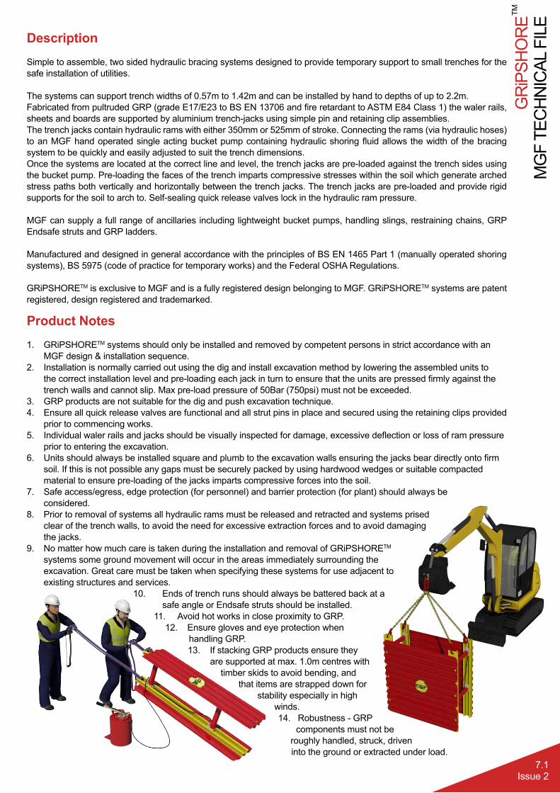
DescriptionSimple to assemble, two sided hydraulic bracing systems designed to provide temporary support to small trenches for the safe installation of utilities.
The systems can support trench widths of 0.57m to 1.42m and can be installed by hand to depths of up to 2.2m.Fabricated from pultruded GRP (grade E17/E23 to BS EN 13706 and fire retardant to ASTM E84 Class 1) the waler rails, sheets and boards are supported by aluminium trench-jacks using simple pin and retaining clip assemblies.The trench jacks contain hydraulic rams with either 350mm or 525mm of stroke. Connecting the rams (via hydraulic hoses) to an MGF hand operated single acting bucket pump containing hydraulic shoring fluid allows the width of the bracing system to be quickly and easily adjusted to suit the trench dimensions.Once the systems are located at the correct line and level, the trench jacks are pre-loaded against the trench sides using the bucket pump. Pre-loading the faces of the trench imparts compressive stresses within the soil which generate arched stress paths both vertically and horizontally between the trench jacks. The trench jacks are pre-loaded and provide rigid supports for the soil to arch to. Self-sealing quick release valves lock in the hydraulic ram pressure.
MGF can supply a full range of ancillaries including lightweight bucket pumps, handling slings, restraining chains, GRP Endsafe struts and GRP ladders.
Manufactured and designed in general accordance with the principles of BS EN 1465 Part 1 (manually operated shoring systems), BS 5975 (code of practice for temporary works) and the Federal OSHA Regulations.
GRiPSHORETM is exclusive to MGF and is a fully registered design belonging to MGF. GRiPSHORETM systems are patent registered, design registered and trademarked.
Product Notes1. GRiPSHORETM systems should only be installed and removed by competent persons in strict accordance with an
MGF design & installation sequence.2. Installation is normally carried out using the dig and install excavation method by lowering the assembled units to
the correct installation level and pre-loading each jack in turn to ensure that the units are pressed firmly against the trench walls and cannot slip. Max pre-load pressure of 50Bar (750psi) must not be exceeded.
3. GRP products are not suitable for the dig and push excavation technique.4. Ensure all quick release valves are functional and all strut pins in place and secured using the retaining clips provided
prior to commencing works.5. Individual waler rails and jacks should be visually inspected for damage, excessive deflection or loss of ram pressure
prior to entering the excavation.6. Units should always be installed square and plumb to the excavation walls ensuring the jacks bear directly onto firm
soil. If this is not possible any gaps must be securely packed by using hardwood wedges or suitable compactedmaterial to ensure pre-loading of the jacks imparts compressive forces into the soil.
7. Safe access/egress, edge protection (for personnel) and barrier protection (for plant) should always beconsidered.
8. Prior to removal of systems all hydraulic rams must be released and retracted and systems prisedclear of the trench walls, to avoid the need for excessive extraction forces and to avoid damagingthe jacks.
9. No matter how much care is taken during the installation and removal of GRiPSHORETM
systems some ground movement will occur in the areas immediately surrounding theexcavation. Great care must be taken when specifying these systems for use adjacent toexisting structures and services.
10. Ends of trench runs should always be battered back at axxxxsafe angle or Endsafe struts should be installed.
11. Avoid hot works in close proximity to GRP.12. Ensure gloves and eye protection when
xxxhandling GRP.13. If stacking GRP products ensure they
xare supported at max. 1.0m centres with timber skids to avoid bending, and
that items are strapped down for stability especially in high
winds.14. Robustness - GRPvxxxcomponents must not be xxxroughly handled, struck, driven
xxxxinto the ground or extracted under load.

MG
F TE
CH
NIC
AL F
ILE
GR
iPSH
OR
E
7.2Issue 2
TM
Product Notes15. Suitable soils: made ground such as soft cohesive and loose granular fill which is generally self-supporting in the
short term and where no ground water is present.16. Unsuitable soils: ground such as very soft clays and silt or peat or in excavations where the trench walls are
collapsing or groundwater is present.17. Vertishore Rail Systems: Vertishore systems rely solely upon soil arching theory to support trench walls. Therefore
never enter a trench unless fully pre-loaded vertishore rails are securely installed either side of the point of entry.18. Box Systems: during installation and removal always ensure any operative in a trench is within fully assembled units
extending vertically to the top of the trench.19. Sheets and Walers: during installation and removal always ensure any operative in a trench greater than 1.0m deep
is within fully assembled frames.20. GRiPSHORETM solutions are offered based on a competent person supervising the excavation and installation of the
support systems. The competent person must be capable of confirming the soil conditions and local environment aresuitable for the design, that the dimensions of the proposed excavation are suitable for the system deployed and thatsufficient trench jacks are loading the soil prior to entry. If the proposed works deviate from the design and / or site conditions vary, immediately secure the excavation (back filling) and seek a re-design. If in doubt, please contactMGF DSL (01942 420704).
21. GRiPSHORETM systems are designed to rely on trench jacks for overall stability, walers, sheets and boards/ panelsare provided to spread the trench jack loads into the soil and prevent ravelling / local spalling of the trench wallsbetween the jacks. The choice of system deployed will therefore depend upon a risk assessment of the proposedworks. In general full sheeting / boarding would be advisable for longer duration works and/or where the trench wallstability for the duration of the proposed works is questionable (e.g. variable soils / extensive service crossings).
22. During installation and removal sequences assembled waler rails and boxes provide a short term safe working areafor operatives when having to temporarily release individual jacks to lift or lower the systems. As a general rule itis safe to excavate up to 1000mm below a loaded jack during the installation sequence. Visit www.mgf.ltd.uk forexamples of installation guides
23. GRiPSHORETM systems are ideal for reactive type work which is short term in nature and has to cope with fastchanging site constraints. It is therefore important that during this type of work the Temporary Works Supervisoris mindful of the Trench Jacking Theory Checks listed in this document and that the spacing rules in particular areobeyed.
24. Prior to loading a jack without a backing board it is essential that a min 500mm long even bearing is provided againstthe waler rail to avoid localised overloading of the soil.
25. Loading jacks against highway pavement construction (generally presenting very hard and uneven surfaces) canmake installing jacks difficult. It is recommended that either the jacks are located so as to load the soil immediately beneath the pavement construction (recommended to batter the pavement back slightly in this case) or that the pavement construction is trimmed back and smoothed out to provide an even bearing and that timber blocks/suitable fill is used to pack out where necessary to maintain an even loading of the trench walls.
26. Check trench service crossings for any soils or materials (including boulders, concrete or road construction) thatcould dislodge and fall/collapse onto operatives and if identified ensure that a jack is placed so as to prevent this or that an exclusion zone is established.
27. Do not work underneath service crossings unless an engineered support system is correctly installed or the servicehas been inspected and confirmed to be stable by a competent person.
GR
iPSH
OR
EM
GF
TEC
HN
ICAL
FIL
E
7.3Issue 2
TM
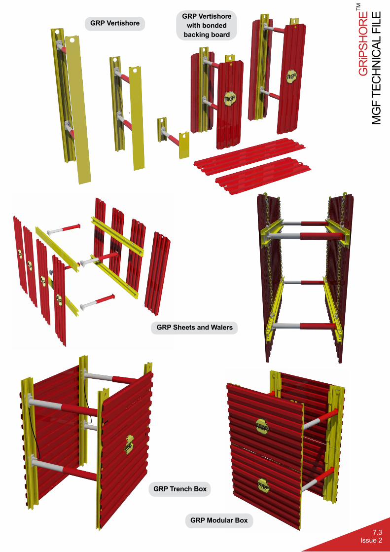
GRP VertishoreGRP Vertishore
with bonded backing board
GRP Trench Box
GRP Modular Box
GRP Sheets and Walers

MG
F TE
CH
NIC
AL F
ILE
GR
iPSH
OR
E
7.4Issue 2
TM
Trench Jacking PrinciplesUsed in the United States for the last 50 years, soil arching or trench jack theory explains that when hydraulic struts pressurise the sides of an excavation that micro movements create compressive stresses into the soil that join together in an arch shape between hydraulic struts. This occurs in both the horizontal and vertical plane creating a protective area around the shoring system.Only small amounts of earth within the soil arch can enter the trench, referred to as ravelling.Trench walls must remain stable long enough for the trench jacks to be deployed and loaded.
Do not extend the trench more than 0.5m beyond the rail

GR
iPSH
OR
EM
GF
TEC
HN
ICAL
FIL
E
7.5Issue 2
TM
Ground Type Description Recommended Pre Load
Made Ground
Loose fil 600psi
Medium compacted fil 500psi
Rock fill, well compacted hardcor 400psi
Clays
Very soft DO NOT USE
Soft 600psi
Firm 500psi
Stiff 450psi
Very stiff 400psi
Gravels
Very loose DO NOT USE
Loose 600psi
Medium dense 500psi
Dense 450psi
Very dense 400psi
Sand
Very loose DO NOT USE
Loose 750psi
Medium dense 500psi
Dense 450psi
Very dense 400psi
Slightly cemented 400psi
Organic Peat / Silt DO NOT USE
Trench Jacking Theory Checks
Trench Jack Recommended Pre-loads
Temporary Works DesignDesign Calculations
MGF Design Services Ltd, Grant House, Lockett Road, Ashton in Makerfield, Wigan, WN4 8DE T: 01942 402704 F: 01942 402701 E: [email protected] W: www.mgf.ltd.uk
Commitment • Innovation • Sustainability
4. GRIPSHORETM DESIGN SOLUTION SUMMARYTrench Jacking Theory ChecksExcavation proportions
Trench Width >600 and <1400mmTrench Length >1.5 Width (Trench lengths can be extended unsupported beyond
jacks by up to 500mm)
Trench Depth <2200mm (This includes any reduced level dig or step / slope)
Trench Jack SpacingTop Jacks bearing onto soil >150mm and <600mm below surfaceHorizontal Jack spacing >600mm <2000mmVertical jack spacing <1200mmBottom jacks max 600mm above dig depth**This may be extended to 1000mm during installation and removal of box systems or subject to design checks
Surcharging
Max 12t excavator, max 5kN/m2 parallel to trenchSuitable GRIPSHORETM Solutions
Method of Install Dig & Place / Dig and Lower – Lowering Units as work proceeds
Max. System Deflection (mm) < 50
Max. Load on 30/60kN Jack (kN)) 11kN
Max Pressure on 16.5kN/m2 Board 11.8kN/m2 (Support IT Output)
Type Vertishore Sheet & Waler Rail
Trench Box Modular Box SingleTrenchJacks
Jack 1 lvl 30/60kN** @-0.200m LVL
60kN @-0.200m LVL
60kN @-0.200m LVL
Not suitable 30kN @-0.150 to-0.450m LVL
Jack 2 lvl 30/60kN** @-0.900
60kN @-0.900
60kN @-0.900
Not suitable 30kN @-0.600 to-1.200m LVL
Jacks 4No Type B1 4No Type B1 4No Type B1 Not suitable 4No Type B1
Rails 4No1600mmVertical
4No1600mmHorizontal
N/A N/A 8No 500mmVertical
Type ofBoard
**With integral500 boardsJack = 60kN
6No1500x500
N/A N/A N/A

MG
F TE
CH
NIC
AL F
ILE
GR
iPSH
OR
E
7.6Issue 2
TM
* Subject to max. 1.7m simplysupported span or 0.6m cantilever
Type GRP RailGRP Material Grade E23
Weight 3.85kg/mSection Modulus 23.5cm3
SWL Moment Capacity 3.42kNm *
** Subject to max. 1.5m simply supported span or 0.6m cantilever
Type GRP Panel/Sheet
GRP Material Grade E17Weight 3.34kg/m
Section Modulus 27.4cm3/mSWL Moment Capacity 3.14kNm/m **
[1] Type A Trench Jack [2] Type B1 Trench Jack *** 30kN for Vertishore rail without bonded
backing board
Hydraulic Trench Jack Single ActingMaterial Aluminium
Bore 50.8mmWeight 5.7kg[1] / 8kg[2]
Axial SWL 60kN / 30kN***Approx. Stroke 350mm[1] / 525mm[2]
Working Temp Range -20ºC to +50ºC
Hydraulic Bucket Pump Single ActingProduct ID 1.604Capacity 10 litres
Shoring Fluid Houghto Safe SF25Installation Pressure 0-750 psi
Weight 12kg (empty)
The pump is used to extend and retract the single acting hydraulic rams. The pumps contain bio-degradable Houghto Safe SF25 shoring fluid. During the Summer months the shoring fluid is diluted with water at a ratio of 3 parts water to 1 part Houghto Safe SF25. In the Winter the mix ratio is 1:1.Maximum recommended installation pressure 750psi (50 Bar).
The GRiPSHORETM range utilise 2 different types of hydraulic trench jacks, Type A: 550 - 900mm (5.7kg) and Type B1: 850 - 1375mm (8kg).
GRP Rail Profil
GRP Panel/Sheet Profil
GRP Hydraulic Ancillaries

GR
iPSH
OR
EM
GF
TEC
HN
ICAL
FIL
E
7.7Issue 2
TM
GRP Sheets and Walers
[1] 1600mm GRP Waler [2] 2100mm GRP Waler* Max. 2200mm subject to design checksAssembled weight based on Type A Struts
System SWL 16.5kN/m2
Max Trench Depth 2000mm*Trench Width 620mm - 1420mm
Max understrut clearance 600mmClearance between struts 1060mm[1] / 1560mm[2]
Assembled Frame Weight 24kg[1] / 28kg[2]
The lightweight system can be rapidly assembled and installed by hand where access is limited, without the need for an excavator and without the requirement for operatives to enter an unsupported trench.Endsafe struts are available to close off the ends of a trench providing extra protection from loose materials falling into the excavation (see page 7.11 for further details).With a SWL of 16.5kN/m2 the system is suitable for use in most trenches up to a depth of 2.0m (2.2m subject to design checks).
Product Description Product ID Weight (kg)1.6m GRP Waler 1.090 6.22.1m GRP Waler 1.100 8.11.5m GRP Sheet 3.006 5.02.0m GRP Sheet 3.007 6.7
Excavating can continue up to 400mm below the toe of the sheet during installation provided jacks are loaded.

MG
F TE
CH
NIC
AL F
ILE
GR
iPSH
OR
E
7.8Issue 2
TM
GRP Vertishore Rail with or without bonded backing board
[1] Without backing board [2] With backing board* Max. 2200mm subject to design checks
Assembled weight based on Type A Struts
Backing Board Width 500mmMax Trench Depth 2000mm*
Trench Width 570mm - 1420mmMax understrut clearance 570mm
Strut SWL 30kN[1] / 60kN[2]
Assembled Weights 9.5 - 27.6kg[1] / 36.4 - 44kg[2]
The lightweight system can be rapidly assembled and installed by hand where access is limited, without the need for an excavator and without the requirement for operatives to enter an unsupported trench.MGF recommend a minimum of 3 units be installed at once and that operatives only work between loaded Vertishores.The system provides a minimum 570mm of clearance below the bottom strut.MGF recommend that any unsupported trench ends do not extend greater than 0.5m beyond the systems. With a trench jack SWL of 30/60kN suitable for use in most trenches up to a depth of 2.0m (2.2m subject to design checks). The trench jacks are linked by hydraulic hoses allowing safe install and removal from outside the trench.
Product Description Product ID Weight (kg)0.5m Vertishore Rail 1.060 1.91.6m Vertishore Rail 1.070 6.2
1.6m Vertishore Rail w/ Bonded Board 1.075 12.52.1m Vertishore Rail 1.080 8.1
2.1m Vertishore Rail w/ Bonded Board 1.085 16.1
Max. spacing between installed Vertishores (without backing board) is 1.5m centre to centre.
Max. spacing between installed Vertishores (with bonded backing board) is 2.0m centre to centre.
GR
iPSH
OR
EM
GF
TEC
HN
ICAL
FIL
E
7.9Issue 2
TM
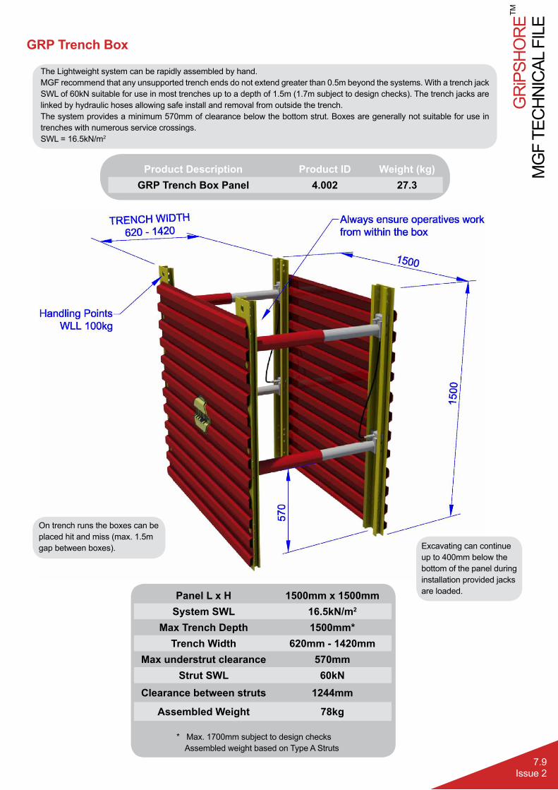
GRP Trench Box
Panel L x H 1500mm x 1500mmSystem SWL 16.5kN/m2
Max Trench Depth 1500mm*Trench Width 620mm - 1420mm
Max understrut clearance 570mmStrut SWL 60kN
Clearance between struts 1244mm
Assembled Weight 78kg
* Max. 1700mm subject to design checksAssembled weight based on Type A Struts
The Lightweight system can be rapidly assembled by hand. MGF recommend that any unsupported trench ends do not extend greater than 0.5m beyond the systems. With a trench jack SWL of 60kN suitable for use in most trenches up to a depth of 1.5m (1.7m subject to design checks). The trench jacks are linked by hydraulic hoses allowing safe install and removal from outside the trench.The system provides a minimum 570mm of clearance below the bottom strut. Boxes are generally not suitable for use in trenches with numerous service crossings.SWL = 16.5kN/m2
Product Description Product ID Weight (kg)GRP Trench Box Panel 4.002 27.3
On trench runs the boxes can be placed hit and miss (max. 1.5m gap between boxes). Excavating can continue
up to 400mm below the bottom of the panel during installation provided jacks are loaded.

MG
F TE
CH
NIC
AL F
ILE
GR
iPSH
OR
E
7.10Issue 2
TM
GRP Modular BoxA lightweight, modular shoring solution for excavations up to 2.0m deep (2.2m subject to design checks) with widths from 620mmm to 1420mm. GRP Modular Box panels create a working area 1.5m wide and a minimum under strut clearance of 570mm to allow services to pass. Due to the soil arch created by the hydraulic struts, GRP Modular Boxes can be set out with a clear space of up to 1.5m between boxes making an efficient solution for longer trench runs.Designed to withstand a maximum safe working load of 16.5kN/m², for use in made ground such as soft cohesive and loose granular fill which is generally self-supporting in the short term and where no ground water is present. Boxes are generally not suitable for use in trenches with numerous service crossings. To assist with installation tubular GRP connecting poles can be provided upon request.
Product Description Product ID Weight (kg)GRP Modular Box Panel 4.001 19
GRP Modular Box Connecting Pole 4.003 2
* Max. 2200mm subject to design checksAssembled weight based on Type A Struts
Panel L x H 1500mm x 1000mmSystem SWL 16.5kN/m2
Max Trench Depth 2000mm*Trench Width 620mm - 1420mm
Max understrut clearance 570mmStrut SWL 60kN
Clearance between struts 1244mm
Assembled Weight 50kg per unit
On trench runs the boxes can be placed hit and miss (max. 1.5m gap between boxes).
Excavating can continue up to 400mm below the bottom of the panel during installation provided jacks are loaded.
GR
iPSH
OR
EM
GF
TEC
HN
ICAL
FIL
E
7.11Issue 2
TM
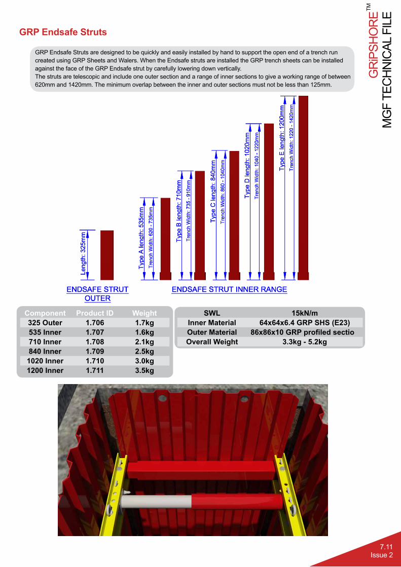
GRP Endsafe Struts
GRP Endsafe Struts are designed to be quickly and easily installed by hand to support the open end of a trench run created using GRP Sheets and Walers. When the Endsafe struts are installed the GRP trench sheets can be installed against the face of the GRP Endsafe strut by carefully lowering down vertically.The struts are telescopic and include one outer section and a range of inner sections to give a working range of between 620mm and 1420mm. The minimum overlap between the inner and outer sections must not be less than 125mm.
SWL 15kN/mInner Material 64x64x6.4 GRP SHS (E23)Outer Material 86x86x10 GRP profiled sectioOverall Weight 3.3kg - 5.2kg
Component Product ID Weight325 Outer 1.706 1.7kg535 Inner 1.707 1.6kg710 Inner 1.708 2.1kg840 Inner 1.709 2.5kg1020 Inner 1.710 3.0kg1200 Inner 1.711 3.5kg
MG
F TE
CH
NIC
AL F
ILE
GR
iPSH
OR
E
7.12Issue 2
TM
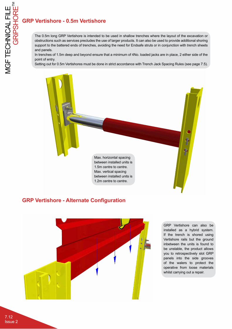
The 0.5m long GRP Vertishore is intended to be used in shallow trenches where the layout of the excavation or obstructions such as services precludes the use of larger products. It can also be used to provide additional shoring support to the battered ends of trenches, avoiding the need for Endsafe struts or in conjunction with trench sheets and panels.In trenches of 1.5m deep and beyond ensure that a minimum of 4No. loaded jacks are in place, 2 either side of the point of entry.Setting out for 0.5m Vertishores must be done in strict accordance with Trench Jack Spacing Rules (see page 7.5).
GRP Vertishore - 0.5m Vertishore
GRP Vertishore can also be installed as a hybrid system. If the trench is shored using Vertishore rails but the ground inbetween the units is found to be unstable, the product allows you to retrospectively slot GRP panels into the side grooves of the walers to protect the operative from loose materials whilst carrying out a repair.
Max. horizontal spacing between installed units is 1.5m centre to centre.Max. vertical spacing between installed units is 1.2m centre to centre.
GRP Vertishore - Alternate Configuration

GR
iPSH
OR
EM
GF
TEC
HN
ICAL
FIL
E
7.13Issue 2
TM
GRiPSHORE Lifting / Handling Accessories
Chains
Product Description WLL (Te) Length (m) Weight (kg)4 Leg Handling Chain 3.0 1.2 8.3
Restraining Chain (hook) 0.47 1.2 2.0Restraining Chain (shackle) 0.47 1.2 1.75
Slings
MGF can provide 1Te endless round slings to assist with the installation and removal of GRiPSHORETM.The slings are simply looped through the handling holes / lifting points on the GRiPSHORETM units.