grid code, distribution code, standards for transmission ... · pdf filefor transmission...
TRANSCRIPT

TRA CODES & STANDARDS: KERC - 1 - 1
KARNATAKA ELECTRICITY REGULATORY
COMMISSION
GRID CODE,
DISTRIBUTION CODE,
STANDARDS
FOR
TRANSMISSION SYSTEM
AND
DISTRIBUTION SYSTEM
6th & 7th Floor, Mahalakshmi Chambers,
# 9/2, Mahatma Gandhi Road, Bangalore –560 001,
Tel: 91-80-5320213,214, Fax:91-80-5320338 E mail:[email protected] Web:www.kerc.org

TRA CODES & STANDARDS: KERC - 2 - 2
Karnataka Electricity Regulatory Commission
INDEX Sl.No Particulars Page No.
1 Grid Code 9-138
2 POM Code-1
Power Generation Planning &
Security Standard
141-160
3 POM Code-2
Power Generation Management &
Operating Standard
161-172
4 POM Code-3
Transmission System Planning &
Security Standard
173-190
5 POM Code-4
Transmission System Management &
Operating Standard
191-204
6 Metering Code 207-213
7 POM Code-5
Metering and Protection Standard
215-223
8 Safety Standard (Transmission lines
& Sub-Stations)
227-247
9 Distribution Code 251-284
10 DPCOM-1
Distribution System Planning &
Security Standard
287-305
11 DPCOM-2
Distribution System Construction,
Operation & Maintenance Standard
307-323
12 DPCOM-3
Safety Standard for Distribution
System
325-335

TRA CODES & STANDARDS: KERC - 3 - 3
KARNATAKA ELECTRICITY REGULATORY COMMISSION
GRID CODE

TRA CODES & STANDARDS: KERC - 4 - 4
GRID CODE
CONTENTS
SECTION – 1 INTRODUCTION 9-14
Section – 2 DEFINITIONS 15-33
Section – 3 MANAGEMENT OF GRID CODE 34-39
Section – 4 SYSTEM PLANNING 40-72
Section – 5 CONNECTION CONDITIONS 73-82
Section – 6 OPERATION PLANNING AND
SECURITY
83-97
Section – 7 SYSTEM OPERATION, METERING,
PROTECTION, DESPATCH AND
CONTROL
98-103
Section – 8 MONITORING OF GENERATION
AND DRAWAL
104-107
Section – 9 CONTINGENCY PLANNING 108-113
Section – 10 CROSS BOUNDARY SAFETY 114-116
Section – 11 SAFETY AND LINE CLEAR
PERMITS
117-125
Section – 12 COMMUNICATION AND DATA
ACQUISITION
126-128
Section - 13 OPERATIONAL EVENT,
INCIDENT/ACCIDENT
REPORTING
129-134
Section - 14 DATA REGISTRATION 135-138

TRA CODES & STANDARDS: KERC - 5 - 5
GRID CODE
SECTION-1
INTRODUCTION
1.1 Introduction:
1.1.1 The Indian Power System is a conglomeration of a number of
Utilities, State Electricity Boards, (some of these at present are
undergoing restructuring) Power Corporations, Power Grid
Corporation of India, National Thermal Power Corporation, National
Hydro Power Corporation etc. Restructuring of several State
Electricity Boards is under process. Each State has its own Power
Grid and the Inter State Transmission Lines interconnect most of
these Power Grids. Some of these Inter State Transmission Lines are
constructed and operated by Power Grid Corporation of India.
Similarly the Central Sector Generation of Hydro, Thermal, and
Nuclear Power Stations are constructed and operated by National
Hydropower Corporation, National Thermal Power Corporation and
NPC respectively. The Power Grid Corporation of India has been
identified as the Central Transmission Utility. The Indian Electricity
Grid Code approved by the CERC is applicable for planning and
operation of all the Inter State Transmission Lines and the Central
Sector Power Stations.
1.1.2 As far as Karnataka Power Grid is concerned, at present, the
Karnataka Power Transmission Corporation Limited has been
declared as the Transmission Utility under Section 27-B of Indian
Electricity Act, 1910. The following functions are to be carried out by
the State Transmission Utility:

TRA CODES & STANDARDS: KERC - 6 - 6
a. Transmission of Energy through the Intra-state Transmission
System of Karnataka Power Grid and bulk supply to Distribution
& Retail Supply Licensees,
b. Planning and co-ordination for the State Power Grid with-
i. Central Electricity Authority;
ii. Central Transmission Utility;
iii. Southern Regional Electricity Board;
iv. State Government;
v. Generating Companies;
vi. Distribution & Retail Supply Licensees;
c. Supervision and control of the State Power Grid;
d. Complying with, and ensure compliance by others in the
State, the directions the Central Transmission Utility may give
from time to time in respect of matters affecting the
integrated grid operation of Inter-State Transmission System.
1.1.3 In order to perform the above task, The Karnataka Electricity
Regulatory Commission has formulated this "KARNATAKA
ELECTRICITY GRID CODE". This Grid Code is applicable for the
Karnataka Power Grid only and for the Inter State Transmission,
Indian Electricity Grid Code shall be applicable.
1.2 Structure of the Grid Code:
This Grid Code consists of 14 Sections as follows:
1.2.1 Section-1: Introduction - Outlines the broad features of the Grid
Code.
1.2.2 Section-2: Definitions - The various terms used in the Grid Code are
defined.
1.2.3 Section-3: Management of Grid Code - The Grid Code is a live
document and has to be periodically reviewed by a competent

TRA CODES & STANDARDS: KERC - 7 - 7
panel as and when required in the light of experience gained. This
section formulates the procedures for the same.
1.2.4 Section-4: System Planning code - Specifies the technical and
design criteria and the procedures to be applied by the State
Transmission Utility and other Users for planning and development of
the Power System.
1.2.5 Section-5: Connectivity Conditions - Specifies the technical criteria
and standards to be complied with by the Transmission Licensee,
the Generating Company, the Distribution & Retail Supply Licensees
and other Users connected or seeking connection to the
Transmission System.
1.2.6 Section-6: Operation Planning and Security - Specifies the process
by which the Transmission Licensee has to carry out the Planning of
Power System Operation, including interface co-ordination with the
users, fixing the parameters for Operation margin, contingency
reserve, demand control etc., for a satisfactory grid operation and
System Integrity.
1.2.7 Section-7: System operation metering, protection, despatch and
control code - Specifies the procedure to be adopted for the
scheduling of despatch of the Generating Units to meet the
demand and drawal allocations, the management of frequency
and voltages in the Extra High Voltage system, the minimum
requirement of protection levels and metering specifications for the
various components of the system.
1.2.8 Section-8: Monitoring of Generation and drawal - Formulates the
procedure to be followed by the State Load Despatch Centre for
monitoring the Generation Output, Active and Reactive reserve
capacity required for evaluation of the performance of Power

TRA CODES & STANDARDS: KERC - 8 - 8
Plants. The monitoring of scheduled drawal is important to ensure
that the Transmission Licensee contributes towards improving the
Regional performance, by observing Grid discipline.
1.2.9 Section-9: Contingency Planning - Formulates the recovery and
normalization of power supply process to be followed by all the
Users in the event of the failure of Karnataka Power Grid, or the
Southern Grid resulting in total or partial collapse of the System
causing blackouts.
1.2.10 Section-10: Cross Boundary Safety - Specifies the requirements for
safe working practices for maintenance of equipment associated
with cross boundary operations and also the procedure to be
followed when the work is carried out on electrical equipment
connected to another User's System.
1.2.11 Section-11: Communication and Data acquisition - Specifies the
minimum requirements of Communication and Data Acquisition
Facilities to be provided by each User at interconnection points and
cross boundary circuits.
1.2.12 Section-12: Operational event and Incident/Accident Reporting -
Specifies the details of minimum requirement for the exchange of
information relating to Operations and/or Events on the total System
including the Southern Grid which may have an operational effect.
1.2.13 Section-13: Safety and Line clear Permits - Sets out the procedure
for recording of Line Clear Permits and guidelines for ensuring safety
from electrical hazards to the consumers, general public and
working personnel.
1.2.14 Section-14: Data Registration - Specifies a list of all the data required
by the Transmission Licensee which is to be provided by the Users
and the data required by the Users to be provided by the

TRA CODES & STANDARDS: KERC - 9 - 9
Transmission Licensee at the required time specified in the various
Sections of the Grid Code.
1.3 Implementation and operation of the Grid Code:
1.3.1 The State Transmission Utility shall be responsible for implementation
of the Grid Code. All the Users shall comply with the Grid Code and
assist the State Transmission Utility in this regard. The Users must
provide all the required information and reasonable rights of
access, service and facilities necessary for implementation of the
Grid Code.
1.3.2 If any User has any difficulty in complying with any of the provisions
of the Grid Code, he shall immediately, without delay, inform the
same to the State Transmission Utility and shall remedy his non-
compliance promptly.
1.3.3 Consistent failure in compliance with the Grid Code may lead to
disconnection of the User‘s plant or Apparatus.
1.3.4 The operation of the Grid Code shall be reviewed regularly by the
Grid Code Review Panel in accordance with the provisions of the
relevant Section of the Grid Code.
1.4 Limitations of the Grid Code:
1.4.1 The Grid Code contains procedures for the management of day to
day technical situations in the Power Grid, taking into account a
wide range of operational conditions likely to be encountered
under both normal and abnormal conditions.
1.4.2 The Grid Code cannot foresee all the possible operating conditions.
Users must therefore understand and accept that the Transmission
Licensee, in such unforeseen circumstances, may be required to
act decisively to discharge his obligations under the License. Users

TRA CODES & STANDARDS: KERC - 10 - 10
shall provide such reasonable cooperation and assistance as the
Transmission Licensee may require in such circumstances.
1.5 Procedures to settle disputes:
1.5.1 In the event of any dispute regarding interpretation between any
User and the Transmission Licensee, the matter shall be referred to
Karnataka Electricity Regulatory Commission. In the event of any
conflict between the parties regarding any provision of the Grid
Code, the Karnataka Electricity Regulatory Commission will
proceed to settle the issue.
***
SECTION-2
DEFINITIONS

TRA CODES & STANDARDS: KERC - 11 - 11
In the Grid Code the following words and expressions shall, unless the
subject matter or context otherwise requires or is inconsistent therewith,
bear the following meanings:
Act The Karnataka Electricity Reform Act, 1999.
Active Energy The electrical energy produced, flowing or supplied by
an electric circuit during a time interval, being the
integral with respect to time of the instantaneous
power, measured in units of watt-hours or standard
multiples thereof, i.e.,
1000 Wh =1 kWh
1000 kWh = 1 MWh
1000 MWh = 1 GWh
1000 GWh = 1 TWh
Active Power The product of voltage and the in-phase component
of alternating current measured in units of watts and
standard multiples thereof, i.e.,
1000 Watts = 1 kW
1000 kW = 1 MW
1000 MW = 1 GW
1000 GW = 1 TW
Agency A term used in various sections of the Grid Code to
refer to utilities that utilize the Intra-Transmission System.
Apparatus All equipment, in which electrical conductors are used,
supported or of which they may form a part. In safety
coordination this also means High Voltage electrical
circuits forming part of a system on which safety
precautions may be applied to allow work and/or

TRA CODES & STANDARDS: KERC - 12 - 12
testing to be carried out on a system.
Apparent Power The product of voltage and alternating current
measured in units of volt-amperes and standard
multiples thereof, i.e.,
1000 VA = 1 kVA
1000 kVA = 1 MVA
Area of supply Area designated in the licence for carrying out the
licenced activity.
Automatic
Voltage
Regulator (AVR)
A continuously acting automatic excitation system to
control a Generating Unit terminal voltage.
Auxiliaries All the plant and machinery required for the
Generating Unit's functional operation that do not form
part of the Generating Unit.
Availability The capability of the Generating Unit expressed in MW.
"Fully Available" shall mean that the Generating Unit is
available to its contracted capacity. In respect of the
Transmission System, "Availability" shall mean the time in
hours the Transmission System is capable of transmitting
Electricity at its rated voltage from the supply point to
the delivery point and expressed as a percentage of
Annual Availability.
Backing Down Reduction of generation on instructions from
SLDC/SRLDC by a Generating Unit under abnormal
conditions.
Back-up
protection
Protection equipment or systems which are intended to
operate when a system fault is not cleared in due time

TRA CODES & STANDARDS: KERC - 13 - 13
because of failure or inability of the Main Protection to
operate or in case of failure to operate a circuit
breaker other than the associated circuit breaker.
Black Start The procedure necessary for a recovery from a Total
Shutdown or Partial Shutdown without the availability of
electricity from external sources.
Black Start
Capability
An ability in respect of a Black Start Station, for at least
one of its Generating Units or CCGT Units to Start-Up
from Shutdown and to energize a part of the system
and be synchronized to the system upon instruction
from the State Load Dispatch Centre, within two hours,
without any external supply.
Black Start
Stations
Power Stations having Black Start Capability.
Bulk supply The sale of Electricity to any person for resale such as,
supply given to a Retail Supply Licensee for purposes
of distribution and resale in his area of supply.
Bulk Supplier ―Bulk Supplier‖ means any person who is authorized to
carry out bulk power supply.
Bulk Supply
Licensee
Any person/Company authorized by KERC for
engaging in the business of bulk supply of electricity.
Captive Power
Plant (CPP)
A Power Plant primarily operated to meet a captive
demand and also connected to the Transmission/
Distribution Systems. Such a plant shall hold valid
consent under Section 17 of the Act and permission for
sale of surplus power to the Transmission/Distribution &
Retail Supply Licensees.

TRA CODES & STANDARDS: KERC - 14 - 14
Caution Notice A notice conveying a warning against interference.
CBIP Central Board of Irrigation and Power.
CCGT Combined Cycle Gas Turbine.
CEA Central Electricity Authority.
Central
Transmission
Utility (CTU)
Any Government Company notified by the Central
Government under section 27A of the Electricity
Regulatory Commission Act, 1998.
CERC Central Electricity Regulatory Commission.
Connected
Planning Data
Actual Data replacing estimated values assumed for
planning purposes.
Connection The electric power lines and electrical equipment used
to effect a connection of a User's System to the
Transmission System.
Connection
Conditions
Those conditions mentioned in Section 5 (―Connection
Conditions‖) which have to be fulfilled before the Users‘
System is connected to the Grid.
Connection
Point
A Grid Supply Point or Grid Entry Point, as the case may
be.
Consumer A person to whom electrical power is provided.
Contingency
Reserve
The available standby generation over forecast
demand, which is required in the period from 24 hours
ahead down to real time to cover against uncertainties
in Generating Plant availability and against errors in
forecast.
Control Engineer A person identified as having responsibility for cross
boundary safety under section 11 ―Cross Boundary
Safety‖ of the Grid Code.

TRA CODES & STANDARDS: KERC - 15 - 15
Customer
Demand Control
Reducing the supply of electricity to a Customer or
disconnecting a Customer in a manner agreed for
commercial purposes between a supplier and its
Customer.
Demand The demand of MW and MVA of electricity (i.e. both
Active and Apparent Power), unless otherwise stated.
Demand Control Any of the following methods of achieving a Load
reduction:
(a) Customer Load Management initiated by Users.
(b) Customer voltage reduction initiated by Users (other
than following an instruction from Load Despatch
Centre).
(c) Customer Load reduction by Disconnection initiated
by Users (other than following an instruction from
Load Despatch Centre).
(d) Customer Load reduction instructed by the Load
Despatch Centre.
(e) Automatic low Frequency Load Disconnection.
(f) Emergency manual Load Disconnection.
Designed
Minimum
Operating Level
The output (in whole MW) below which a Despatch
Unit is generally not allowed to operate according to
prudent operating practice.
Despatch Operational control of an integrated electricity system
involving operations such as:
Assignment of levels of output to specific
Generating Plant or load control devices to effect
the most reliable and economical supply as the

TRA CODES & STANDARDS: KERC - 16 - 16
loads vary,
The control of the operation of extra high voltage
lines, associated substations and equipments,
The scheduling of various types of transactions with
the electric utilities over the interconnecting
Transmission Lines.
De-Synchronize The act of taking a Generating Unit off a system to
which it has been Synchronized.
Disconnection The physical separation of Users or Customers from the
System.
Discrimination The quality where a relay or protective system is
enabled to pick out and cause to be disconnected
only the faulty Apparatus.
Distribution
System
―Distribution System‖ means any system consisting
mainly of cables, service lines and overhead lines,
electrical plant and meters having design voltage of 33
KV and below. The distribution system shall not include
any part of a transmission system except the terminal
equipment used for the supply of electricity to extra
high voltage (66 KV and above) Consumers.
Distribution &
Retail Supply
Licensees
Any person/company authorized by KERC for
engaging in the business of Distribution & Retail Supply
of Electricity.
Drawal The import/export of Electrical Energy from/to the grid.
Earthing Connecting the conducting parts of an equipment or
machinery with the general mass of earth, in such a
manner ensuring at all times an immediate discharge

TRA CODES & STANDARDS: KERC - 17 - 17
of energy without danger, by maintaining the same
efficiently at earth's potential.
Earthing Device A means of providing connection between a
conductor and earth being of adequate strength and
capability.
Emergency
Instruction
A Despatch instruction issued by the Load Despatch
Centre, to a Despatching Unit which may require an
action or response which is outside Generation
Scheduling and Despatch Parameters, Generation and
other relevant Data or Notice to Synchronize.
Excitation
System
The equipment providing the field current of a
machine, including all regulating and control elements,
as well as field discharge or suppression equipment
and protective devices.
Exciter The Source of electrical power providing the field
current of a Synchronous Machine.
External
interconnection
Apparatus for the transmission of electricity to or from the
Karnataka Grid into or out of the Southern Grid.
Fault Current
Interruption Time
The time interval from fault inception until the end of break
time of the circuit breaker.
Frequency The number of alternating current cycles per second
(expressed in Hertz) at which the system is operating.
Generating
Company
―Generating Company‖ means a Company registered
under Company‘s Act, 1956 ( 1 of 1956) and which has
among its objectives the establishment, operation and
maintenance of generating stations.
Generating A Power Station connected to the Transmission System

TRA CODES & STANDARDS: KERC - 18 - 18
Plant and available for Scheduling by the Load Despatch
Centre.
Generating Unit The combination of an Electric Power Generator and its
Prime mover and all of its associated equipment, which
together constitutes a single generating machine
Generation
Schedule
The despatch schedule of a Generating Station.
Generator
capability curve
A diagram, which shows the MW and MVAr capability
limits within which a Generating Unit will be expected
to operate under steady state conditions.
Governor
Deadband
The total magnitude of the change in steady state
speed [expressed as a range of Hz (± xHz) where "x" is a
numerical value] within which there is no resultant
change in the position of the governing valves of the
speed/load Governing System.
Grid Code "Karnataka Electricity Grid Code" - a document
describing the procedures and the responsibilities for
planning and operation of Karnataka Power Grid.
Grid Code
Review Panel or
"Panel"
The Panel with the functions set out in the Grid Code.
Grid Entry Point A point at which a Power Station is connected to the
Transmission System of Karnataka Power Grid.
High Voltage or
HV
Voltages ranging from 650 volts to 33KV.
IE Rules Indian Electricity Rules 1956.
IEC International Electro-Technical Commission
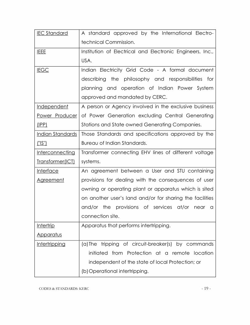
TRA CODES & STANDARDS: KERC - 19 - 19
IEC Standard A standard approved by the International Electro-
technical Commission.
IEEE Institution of Electrical and Electronic Engineers, Inc.,
USA.
IEGC Indian Electricity Grid Code - A formal document
describing the philosophy and responsibilities for
planning and operation of Indian Power System
approved and mandated by CERC.
Independent
Power Producer
(IPP)
A person or Agency involved in the exclusive business
of Power Generation excluding Central Generating
Stations and State owned Generating Companies.
Indian Standards
("IS")
Those Standards and specifications approved by the
Bureau of Indian Standards.
Interconnecting
Transformer(ICT)
Transformer connecting EHV lines of different voltage
systems.
Interface
Agreement
An agreement between a User and STU containing
provisions for dealing with the consequences of user
owning or operating plant or apparatus which is sited
on another user‘s land and/or for sharing the facilities
and/or the provisions of services at/or near a
connection site.
Intertrip
Apparatus
Apparatus that performs intertripping.
Intertripping (a) The tripping of circuit-breaker(s) by commands
initiated from Protection at a remote location
independent of the state of local Protection; or
(b) Operational intertripping.

TRA CODES & STANDARDS: KERC - 20 - 20
Isolating Device A device for achieving Isolation.
Isolation The disconnection of HV Apparatus from the remainder
of the System in which that HV Apparatus is situated.
KERC Karnataka Electricity Regulatory Commission.
KPCL Karnataka Power Corporation Limited.
KPTCL Karnataka Power Transmission Corporation Limited.
KPTCL Site Means a site owned (or occupied pursuant to a lease,
licence or other agreement) by KPTCL in which there is
a Connection Point. For the avoidance of doubt, the
portion of User's site occupied by KPTCL as aforesaid, is
a KPTCL Site.
Lean Period That period in a day when the electrical power
demand is lowest.
Licence Any license granted by KERC.
Licence
Standards
Those standards set out or referred to in the
Transmission/Bulk Supply/Distribution & Retail Supply
Licences.
Load The Active, Reactive or Apparent Power as the context
requires, generated, transmitted or distributed.
Load Factor Load Factor is the ratio of the average power to the
maximum demand. The load factor depends on the
interval of time of the maximum demand and the
period over which the average is taken.
Units consumed in a given period
Load Factor = ----------------------------------------------------------
Maximum Demand x No. of hours in the
period

TRA CODES & STANDARDS: KERC - 21 - 21
Loaded Supplying electrical power to the System.
Local Safety
Instructions
The safety manuals and instructions framed and issued
by the User and KPTCL, setting down the methods and
procedures to be adopted and precautions to be
taken to ensure complete safety to the personnel
carrying out the operation, maintenance and testing of
the plant and apparatus.
Low Voltage or
LV
Voltage not exceeding 650 volts.
Main Protection Protection equipment or system expected to have
priority in initiating either a fault clearance or an action
to terminate an abnormal condition in a power system.
Multiple Point
Connection
Two or more points of Connection interconnected to
each other through the User's System.
Notice to
Synchronize
The amount of time (expressed in minutes) that is
declared by a Generating Company in relation to a
Generator to enable it to be synchronized following the
receipt of an instruction to synchronize.
NPC Nuclear Power Corporation.
Operating
Margin
Contingency Reserve plus Operating Reserve.
Operating
Reserve
The additional output from a Generating Plant, which
must be realizable in real-time operation to correct any
System Frequency fall to an acceptable level, in the
event of a loss of generation, or loss of import from an
External Interconnection, or mismatch between
generation and Demand.

TRA CODES & STANDARDS: KERC - 22 - 22
Operation A scheduled or planned action relating to the
operation of a System.
Operational
Data
Data required under the Operating Codes and/or
Scheduling and Despatch Codes.
Operational
Planning
Planning carried out to achieve, as far as possible, the
standards of security set out in the Transmission
Planning and Security Standard through various time
scales, the matching of generation output with
forecast Demand together with a reserve of
generation to provide a margin, taking into account
outages of the following to which the Power Stations
and/or Customers are connected:
(1) Certain Generating Units,
(2) Parts of the Transmission System, and
(3) Parts of User Systems.
Operational
Procedures
Management instructions and procedures, both for the
Safety Rules and for the local and remote operation of
Plant and Apparatus, issued in connection with the
actual operation of Plant and/or Apparatus at or from
a Connecting Site.
Out of
Synchronism
The condition where a System or Generating Unit can
not meet the requirements to enable it to be
Synchronized.
Outage A total or partial regulation in availability due to repair
and maintenance of the Transmission or Distribution or
Generation facility or defect in Auxiliary System.
Part Load The condition of a Power Plant which is Loaded but is

TRA CODES & STANDARDS: KERC - 23 - 23
not running at its declared availability.
Partial Shutdown A shutdown of a part of the system resulting in failure of
power supply, either from external interconnections or
from the healthy part of the system.
Peak Period That period in a day when the electrical power
demand is highest.
Person Any individual connected with the generation,
transmission, distribution and utilization of electrical
power.
PGCIL Power Grid Corporation of India Limited.
Planned Outage An outage of Generating Plant or part of the
Transmission System, or part of a User's system co-
coordinated by SLDC.
Point of
Connection
An electrical point of connection between the
Transmission System and the User's System.
Point of Isolation The point on Apparatus at which Isolation is achieved.
Power Factor The ratio of Active Power to Apparent Power.
Power Purchase
Agreement
The agreement entered into between the Generating
Company and the Transmission Licensee/Bulk Supply
Licensee/Distribution & Retail Supply Licensee.
Power Station An installation comprising one or more Generating Units
owned and/or controlled by the same Generating
Company.
Protection The schemes and apparatus for detecting abnormal
conditions on a System and initiating fault clearance or
actuating signals or indications.
Protection A group of one or more Protection Relays and/or logic

TRA CODES & STANDARDS: KERC - 24 - 24
Apparatus elements designated to perform a specified Protection
function.
Prudent Utility
Practices
Those practices, methods, techniques and standards,
as modified from time to time, that are generally
accepted for use in the International Electric Utility
Industry, taking into account the prevailing conditions
in India. These shall be the ones commonly used in
electrical utility for engineering and operations such as
the design, engineering, construction, testing,
operation and maintenance of equipment lawfully,
safely, efficiently and economically, as applicable to
the equipment of certain size, service and type. These
practices, methods, standards and acts shall be
adjusted to the extent necessary in order:
1. To conform to operation and maintenance guide
lines recommended by the equipment
manufacturers and suppliers and shall also be in
accordance with the guide lines given in the
relevant IS Code of Practices for such equipments
wherever available,
2. To ensure compliance with the IE Act and Rules and
other related laws,
3. To take into account the site location, including
(without limitation) the climatic, hydrological and
other environmental or general conditions thereof,
4. To conform to energy conservation, and
5. To conform to General Safety Standards.

TRA CODES & STANDARDS: KERC - 25 - 25
Rated MW The "rating plate" MW output of a Generating Unit,
being that output up to which the Generating Unit is
designed to operate.
Reactive Power The product of voltage and current and the sine of the
phase angle between them measured in units of volt-
amperes reactive and standard multiples thereof, i.e.:
1000 VAr. = 1kVAr
1000 kVAr = 1 MVAr
Regulating
Margin
The system voltage and frequency beyond which the
system should not be operated.
Retail Supply ―Retail Supply‖ means the sale of electricity to
consumers.
Responsible
Engineer/
Operator
A person nominated by an User to be responsible for
System control.
Re-
synchronization
The bringing of parts of the System which has gone out
of Synchronism with each other, back into Synchronism.
Safety Co-
ordinator
A person or persons nominated by the Transmission Licensee
and each User to be responsible for the co-ordination of
Safety Precautions at each connection point when work
(including testing) is to be carried out on a system, which
necessitates the application of Safety Precautions on HV
Apparatus.
Safety from the
System
Those conditions which safeguard persons carrying out
the work on a System from the dangers, which are
inherent in the System.
Safety Rules The rules framed by the Users and the Transmission

TRA CODES & STANDARDS: KERC - 26 - 26
Licensee to ensure safety to persons working on
Plant/Apparatus.
Schematic
Diagrams
Diagrams which are a schematic representation of the
HV Apparatus and the connections to all external
circuits at a Connection Site, incorporating its
numbering, nomenclature and labeling.
Single Point
Connection
A single Point of Connection, with no interconnection
through the User's System to another Point of
Connection.
SLDC State Load Despatch Centre.
SREB Southern Regional Electricity Board.
SRLDC Southern Regional Load Despatch Centre.
Standing
Instructions
An instruction issued by SLDC to a Generating
Company whereby, in specified circumstances, the
Generating Company should take specified action, as
though a valid dispatch instruction has been issued by
SLDC.
Start-Up The action of bringing a Generating Unit from
Shutdown to Synchronous Speed.
State
Transmission
Utility (STU)
The utility notified by the Government under Sub-
Section (1) of Section 27B of Indian Electricity Act 1910,
as amended in 1998, and whose functions have been
outlined under Section 55 of Amendments to the
Electricity Supply Act 1948 issued in 1998.
Station
Transformer
A transformer supplying electrical power to the
Auxiliaries of a Power Station, which is not directly
connected to a Generating Unit terminal.

TRA CODES & STANDARDS: KERC - 27 - 27
Supply ―Supply‖ means the Procurement, Distribution and
Provision of electricity by a supplier either for resale or
directly to the Consumers.
Supplier ―Supplier" means any person who holds a licence
under Section 19 of the Act or is granted an exemption
under Section 20 of the Act.
Supervisory
Control and
Data Acquisition
or (SCADA)
The communication links and data processing systems,
which provide information to enable implementation of
requisite supervisory and control actions.
Supply Act Electricity Supply Act, 1948.
Synchronized Those conditions where an incoming Generating Unit or
System is connected to the busbars of another System
so that the frequencies and phase relationships of that
Generating Unit or System as the case may be, and the
System to which it is connected are identical.
Synchronous
Compensation
The operation of rotating synchronous Apparatus for
the specific purpose of either generation or absorption
of Reactive Power.
Synchronous
Speed
That speed required by a Generating Unit to enable it
to be Synchronized to a System.
System Any User System and/or Transmission System, as the
case may be.
System
Constraint
A limitation on the use of a System due to lack of
transmission capacity or other system conditions.
System Margin The margin in any period between
(a) Declared Availability and

TRA CODES & STANDARDS: KERC - 28 - 28
(b) Forecast Demand and the Operating Margin, for
that period.
Total System The KPTCL System and all User Systems in Karnataka.
Transmission
Licence
The Licence granted by KERC for power transmission.
Transmission
Licensee
The holder of a Transmission License issued by KERC.
Transmission
Services
Agreement
The agreement between the Transmission Licensee and
the User in which, subject to certain conditions, the
Transmission Licensee agrees to transmit/wheel
electrical power over its network to the User.
Under
Frequency Relay
An electrical measuring relay intended to operate
when its characteristic quantity reaches the relay
settings by decrease in frequency.
Unit Auxiliary
Transformer
A transformer directly connected to a Generating Unit's
terminals, and which supplies power to Auxiliaries of a
Generating Unit.
User A term utilized in various sections of Grid Code to refer to the
persons using the Karnataka Power Grid, as more
particularly identified in each section of the Grid Code. In
the General Conditions the term means any person to
whom the Grid Code applies.
User Site A site owned (or occupied pursuant to a lease, licence
or other agreement) by a User in which there is a
connection point.
Utility Any person or entity engaged in generation,
transmission, Bulk Supply or Distribution and Retail

TRA CODES & STANDARDS: KERC - 29 - 29
supply of energy, as the case may be.
VVNL Visveswaraya Vidyut Nigama Limited.
***
SECTION-3
MANAGEMENT OF GRID CODE
3.1 INTRODUCTION:
3.1.1 The Karnataka Power Transmission Corporation Limited (KPTCL),
which is the State Transmission Utility (STU) for the State of Karnataka,
which also holds the Transmission License and Bulk Supply License is
required to implement and comply with the Karnataka Electricity

TRA CODES & STANDARDS: KERC - 30 - 30
Grid Code (KEGC), herein after called GRID CODE, and to carry out
periodic review and amendments of the same with the approval of
Karnataka Electricity Regulatory Commission (KERC). A Review
Panel shall be constituted by the Transmission Licensee, as required
in this Section, comprising of the representatives of the Users of the
Transmission System.
3.1.2 No change in this GRID CODE, however small or big, shall be made
without being deliberated upon and agreed to by the GRID CODE
Review Panel and approved by KERC.
3.1.3 The Transmission Licensee will be responsible for managing and
implementing the GRID CODE for discharging its obligations with the
Users. The Transmission Licensee will not be, however, required to
incur any expenditure on account of travel etc., of any other
member of the panel other than its own representative.
3.2 OBJECTIVE:
3.2.1 The objective of this Section is to define the method of
management of GRID CODE documents, implementing any
changes/modifications required and the responsibilities of the
constituents (Users) to effect the change.
3.3 GRID CODE REVIEW PANEL:
3.3.1 The Chairperson of the Grid Code Review panel shall be an
Engineer of the Transmission Licensee not below the rank of Chief
Engineer Electricity of the Transmission Licensee. The Member
Secretary of the Panel shall also be nominated by the Transmission
Licensee. The Panel shall consist of the following members on the
recommendations of the heads of the respective organizations:

TRA CODES & STANDARDS: KERC - 31 - 31
(a) One Chief Engineer or General Manager of Karnataka Power
Corporation Limited (KPCL).
(b) One Chief Engineer of Visveswaraya Vidyut Nigama Limited
(VVNL).
(c) One representative at senior executive level from National
Thermal Power Corporation Limited (NTPC).
(d) One representative at senior executive level from Power Grid
Corporation of India Limited (PGCIL).
(e) One representative at senior executive level from Southern
Regional Electricity Board (SREB).
(f) One representative at senior executive level from each
Distribution & Retail Supply Licensee.
(g) One representative at senior executive level from each of the
IPPs feeding the Karnataka State Power Grid feeding not less
than 50 MW.
(h) One representative from all the IPPs and CPPs of small Power
Plants of less than 50 MW capacity on rotation basis.
(i) One nominee from KERC.
3.3.2 Any other member can be co-opted as a member of the panel
when directed by KERC.
3.3.3 The functioning of the panel shall be co-ordinated by the
Transmission Licensee. The Member Secretary nominated by the
Transmission Licensee shall be the convener.
3.3.4 The Transmission Licensee shall inform all the Users, the names and
addresses of the Panel Chairperson and the Member Secretary at
least 7 days before the first Panel meeting. Any subsequent
changes shall also be informed to all the users by the Transmission
Licensee. Similarly, each User shall inform the names and

TRA CODES & STANDARDS: KERC - 32 - 32
designations of their representatives to the Member Secretary of
the Panel, at least three days before the first Panel meeting, and
shall also inform the Member Secretary in writing regarding any
subsequent changes.
3.4 FUNCTIONS OF THE REVIEW PANEL:
3.4.1 The functions of the Review Panel are as follows:
(a) Maintenance of the GRID CODE and its working under
continuous scrutiny and review.
(b) Consideration of all requests for review made by any User and
publication of their recommendations for changes to the GRID
CODE together with reasons for such changes.
(c) Issue of guidance on interpretation and implementation of the
GRID CODE.
(d) Examination of the problems raised by any User.
(e) Ensuring that the changes/modifications proposed in the GRID
CODE are consistent and compatible with Indian Electricity
Grid Code (IEGC).
(f) Analysis of major grid disturbances soon after their occurrence.
(g) Constitute a committee containing experts in the field of
protection, including at least one member from the
Transmission Licensee for coordination and monitoring of
protection functions for the entire grid, duly making the
required studies for the protective relay settings.
The Review Panel may hold any number of meetings as required
subject to the condition that at least one meeting shall be held in
every three months. Sub-meetings may be held by the Transmission
Licensee with the User to discuss individual requirements and with

TRA CODES & STANDARDS: KERC - 33 - 33
groups of Users to prepare proposals for Panel meeting for a
decision.
3.5 REVIEW AND REVISIONS:
3.5.1 The Users seeking any amendment to the Grid Code shall send
written requests to the Member Secretary of the panel with a copy
to KERC. If the request is sent to KERC directly, the same shall be
forwarded to the Transmission Licensee. The Transmission Licensee
shall, in consultation with the Distribution & Retail Supply Licensees,
Generating Companies, Central Transmission Utility (CTU) and SREB
and such other persons as the KERC may direct, review the GRID
CODE provisions. The Transmission Licensee shall examine the
proposed changes/modifications and circulate the same along
with its comments to all the panel members for their written
comments within a reasonable time frame.
3.5.2 All the comments received shall be scrutinized and compiled by the
Transmission Licensee. These along with Transmission Licensee's
comments shall be sent to all the members for their response in favour
or otherwise, for the proposed change/modification. If necessary, the
Transmission Licensee shall convene a meeting of the panel for
deliberations. The Member Secretary shall present all the proposed
revisions of the Grid Code to the panel for its consideration.
3.5.3 Based on the response received, the Transmission Licensee shall
finalize its recommendation regarding the proposed modification /

TRA CODES & STANDARDS: KERC - 34 - 34
amendment and submit the same along with all the related
correspondence to KERC for approval.
3.5.4 The Transmission Licensee shall send the following reports to the
KERC at the conclusion of each review meeting of the panel:
(a) Reports on the outcome of such review.
(b) Any proposed revision to the Grid Code as the Transmission Licensee
reasonably thinks necessary for achievement of the objectives
referred to in the relevant paragraphs of the Transmission licence.
(c) All written representations and objections submitted by the Users at the
time of review.
3.5.5 All revisions to the Grid Code require the approval of KERC. The
Transmission Licensee shall publish revisions to the Grid Code, after
the approval of KERC. The Transmission Licensee may submit
proposals for relaxation in such cases where Users have difficulties in
meeting the requirements of the Grid Code.
3.5.6 Any change from the previous version shall be clearly marked in the
margin. In addition, a revision sheet shall be placed at the front of the
Revised Version noting the number of every changed Sub-section,
together with reasons for such change.
3.5.7 The Transmission Licensee shall keep copies of the Grid Code with
the latest amendments and shall make it available at a reasonable
cost to any person requiring it. The Transmission Licensee shall keep
an up to date list of recipients of all the copies of the Grid Code.
***

TRA CODES & STANDARDS: KERC - 35 - 35
SECTION-4
SYSTEM PLANNING CODE
4.1 INTRODUCTION:
The System Planning specifies the technical and design criteria and
procedures to be adopted by the Transmission Licensee for the
planning and development of the Transmission System. The Users of

TRA CODES & STANDARDS: KERC - 36 - 36
the Transmission System shall take the "System planning" into
account for planning and development of their own System.
4.1.1 Reinforcements and extensions to the System arise due to many
reasons of which a few are mentioned below:
1. A development on a User's System already connected to the
Transmission System as a User development.
2. Introduction of a new connection point between an User's
System and the Transmission System.
3. The need to increase System capacity, removal of
operational constraints, maintenance of Security Standards and
meeting general increases in Demand.
4. Steady state and transient stability considerations.
5. Cumulative effects of any combination of the above four.
4.1.2 The work of such reinforcement and extension to the Transmission
System may also involve work at a connecting point (entry or exit)
of a Generating Company/Distribution Licensee to the Transmission
System.
4.1.3 The development of the Transmission System must be planned in
advance duly allowing sufficient lead time, considering the
following:
1. Time required for obtaining all the necessary statutory approvals like
PTCC clearance, Forest clearance, Railway clearance, clearance
from aviation authorities, National highways, State highways etc., and
the right of way permissions wherever required,
2. Time required for detailed engineering, design and construction work
to be carried out. This "System Planning", therefore, enforces the time
scales for exchange of information between the Transmission Licensee

TRA CODES & STANDARDS: KERC - 37 - 37
and the User(s). All the concerned parties, wherever appropriate, shall
have due regard to the confidentiality of such information.
4.2 Objective:
4.2.1 This Section formulates the Standards and Procedures for the
"System Planning" to enable the Transmission Licensee in
consultation with the Users, for evolving an efficient, co-ordinated,
secure and economical Transmission System for the Karnataka
Power Grid in order to satisfy the requirements of Demand and
Generation.
4.3 Perspective Plan:
4.3.1 The load forecasting shall be the primary responsibility of Distribution
Licensee within his area of supply. The Distribution and Retail Supply
Licensees shall determine the peak load and energy forecasts of
their areas, for each category of loads for each of the succeeding
10—15 years and submit the same annually by 31st March to the
Transmission Licensee. These shall include the details of demand
forecasts, data methodology and assumptions on which the
forecasts are based. The load forecasts shall be made for each
interconnection point with the Karnataka Power Grid and other
Users and shall include the annual peak load and energy
projections along with the daily load curves. These forecasts shall be
updated annually and also whenever major changes are made in
the existing system. Wherever these forecasts take into
consideration demands for power exceeding 5 MW by a single
consumer, the Distribution Licensee shall personally satisfy himself
regarding the materialization of such a demand.
4.3.2 The Transmission Licensee shall also review the methodology and
assumptions used by the Distribution Licensees in making the load

TRA CODES & STANDARDS: KERC - 38 - 38
forecasts, in consultation with them. The resulting overall forecast will
form the basis of planning for expansion of Transmission System,
which will be carried out by the Transmission Licensee. To maintain
the reliability of the interconnected Regional Power Systems, all
participants must comply with the planning criteria/guidelines of
CEA as updated from time to time.
4.3.3 The Transmission Licensee shall be responsible to prepare and
submit a long term (ten years) plan to the KERC for Generation
expansion and the Transmission System expansion to meet the
future demand in accordance with Section 16.9 of the Transmission
Licence. The planning shall be in conformity with the national
perspective for Power Generation and Transmission plan prepared
by the CEA.
4.3.4 The Transmission Licensee shall forecast the demand for power
within the area of supply for each of the succeeding ten years and
provide to the KERC the details of demand forecasts, data,
methodology and assumptions on which the forecasts are based.
These forecasts shall be periodically updated. A least cost
generation plan for the Karnataka State has to be prepared to
meet the ten years' load demand according to the forecast, after
examining the economic, technical and environmental aspects of
all available alternatives and taking into account the existing
contracted generation resources and effects of demand
management. Similarly, a long term (ten years) plan for the
Transmission System compatible with the above load forecast and
generation plan shall be prepared and submitted to KERC. This shall
also include provision for reactive compensation needed for the
Transmission System.

TRA CODES & STANDARDS: KERC - 39 - 39
4.3.5 The Transmission Licensee shall be responsible for integrating the
load forecasts submitted by each of the Distribution and Retail
Supply Licensees and determining the long-term (10 years) load
forecasts for the State. For determining the requirements for the
entire State, an appropriate diversity factor from the data available
for the previous years shall have to be chosen. The Transmission
Licensee shall satisfy itself regarding the probability of
materialization of bulk loads of consumers with demands above 5
MW in consultation with the Distribution and Retail Supply Licensees
concerned.
4.4 Planning Standards and Procedures:
4.4.1 The power generation expansion planning shall be carried out in
accordance with the "Power Supply Planning and Security
Standard" approved by KERC under Section 16 of the Transmission
Licence. The Transmission System shall be planned in accordance
with the "Transmission System Planning and Security Standard"
approved by KERC under Section 16.3 of the Transmission Licence.
4.5 Planning Data Requirement:
4.5.1 To enable the Transmission Licensee to discharge its responsibilities
under the Transmission Licence by conducting System Studies and
preparation of perspective plans for demand, generation and
transmission as detailed in this section, all the Users shall furnish all
the data to the Transmission Licensee from time to time detailed
under Data Registration Section and categorized as Planning Data
(PD), vide Annexe "A".
4.5.2 To enable the Users to Co-ordinate planning, design and operation
of their plants and systems with the Transmission System they may
seek certain salient data of the Transmission System as applicable

TRA CODES & STANDARDS: KERC - 40 - 40
to them. The Transmission Licensee shall supply these data from
time to time as detailed under Data Registration Section and
categorized as Detailed Transmission System Data vide Annexe "B".
4.6 In addition to the above the above provisions, the planning code of
Indian Electricity Grid Code (IEGC) which call for data exchange
shall also apply to the Generating Companies, CPPs, IPPs,
Transmission Licensee, Utilities and Distribution and Retail Supply
Licensees regarding generation / transmission of energy from Inter
State Transmission Systems.
4.7 The one time data shall be submitted within 6 months from the date
the Grid Code comes into effect, by all the concerned to the
Transmission licensee. The data other than this one time data shall
be made available to the Transmission Licensee on first of April and
first of October every year.

TRA CODES & STANDARDS: KERC - 41 - 41
ANNEXE A
PLANNING DATA REQUIREMENTS
(Clause 4.5.1)
PART-I - GENERATION
(To be furnished by the Generating Company to the Transmission Licensee)
A-1 Standard Planning Data (Generation)
THERMAL
I. GENERAL: -
1. Site: i. Furnish location map to scale showing roads,
Railway lines, Transmission lines, Rivers, and reservoirs if
any.
ii. Coal /Fuel linkage (like Liquid Natural Gas, Naptha.
LSHS/FO etc.)
iii. Furnish information on means of coal transport from
Coal transport from Coal mines in case of pithead
stations or means of coal carriage if coal is to be brought
from distance.
iv. In case of other fuels, Furnish details of sources of fuel
and their transport.
v. Water Sources (Furnish information on availability
of water for operation of the power Station).
vi. Environmental (State whether forest, lands mining
clearance areas are affected).
2. Site Map:
(To scale)
Showing area required for power station coal linkage,
coal yard, water pipe line, ash disposal area, colony
etc.

TRA CODES & STANDARDS: KERC - 42 - 42
3. Approximate period of construction.
4. Guaranteed Plant Load Factor.
5. Annual Generation.
II. Connection:
1. Point of connection Furnish single line diagram of the proposed connection
with the system.
2. Step up voltage for connection in KV
III. Station Capacity:
1. Total Power Station
capacity (MW).
MW
2. No. of Units and Unit
size MW.
State whether development will be carried out in
phases and if so, furnish details.
3. Generator Unit
Data:
i. Steam Turbine- State Type, capacity, steam
pressure, steam temperature etc.
ii. Generator:
a) Type
b) Rating (MVA)
c) Terminal Voltage (KV)
d) Rated Power Factor
e) Reactive Power capability (MVAr) in the range 0.95
leading and 0.85 lagging.

TRA CODES & STANDARDS: KERC - 43 - 43
f) Short Circuit Ratio
g) Direct axis transient reactance (% on MVA rating)
h) Direct axis sub-transient reactance (% on MVA
rating)
i) Auxiliary Power requirement
iii. Generator Transformer / Station Transformer
a) Rated Capacity (MVA)
b) Voltage Ratio (HV/LV)
c) Tap change range (+% to -%)
d) Percentage Impedance (Positive Sequence at Full
load).
A.1.2 Hydro Electric:
1. General:
1. Site Furnish location map to scale showing roads, railway
lines, Transmission lines
2. Site Map (To scale) Map showing proposed dam, reservoir area, water
conductor system, fore bay, powerhouse etc.
3. Submerged Area Furnish information on area of villages submerged,
forestland, agricultural land etc.
4. Approximate period of construction.
5. Annual Generation (Primary Energy, Secondary Energy)
II. Connection:
1. Point of connection Furnish single line diagram of proposed

TRA CODES & STANDARDS: KERC - 44 - 44
connection with the transmission
system
2. Step up voltage for connection KV
III. Station Capacity:
1. Total power station capacity MW State whether development would be
carried out in phases and if so furnish
details
2. No. of Units and unit size MW.
IV. Generation Unit Data:
1. Operating Head (In Mtr) Maximum
Minimum
Average
2. Turbine State type and capacity
3. Generator a) Type
b) Rating (MVA)
c) Terminal Voltage (KV)
d) Rated Power Factor
e) Reactive Power capability (MVAr) in the
range of 0.95 leading and 0.85 of lagging.
f) Short Circuit Ratio
g) Direct axis transient reactance (% on rated
MVA)
h) Direct axis Sub-transient reactance (% on
rated MVA)
i) Auxiliary Power Requirement

TRA CODES & STANDARDS: KERC - 45 - 45
4. Generator - Transformer a) Type
b) Rated Capacity (MVA)
c) Voltage Ratio HV/LV
d) Tap change Range (+ % to - %)
e) Percentage Impedance (Positive sequence
at Full load rating)

TRA CODES & STANDARDS: KERC - 46 - 46
A.2 Detailed Planning Data (Generation)
A.2.1 Thermal Power Stations
I. General:
1. Name of Power Station:
2. No. and capacity of Generating Units (MW):
3. Ratings of all major equipments:
(a) Boilers and Major accessories (Steam temperature/pressure)
(b) Coal Mill (KW)
(c) Feed water Pumps (KW)
(d) ID Fans (KW)
(e) Turbines
(f) Alternators
(g) Generating Unit Transformers (MVA)
(h) Station Transformers
4. Auxiliary Transformers (MVA)
5. Single line diagram of Power Station and switchyard.
6. Relaying and metering diagram.
7. Neutral Grounding of Generating Units.
8. Excitation control (type - E.g. Static Excitation System, Fast Brushless)
9. Earthing arrangements with earth resistance values.
II. Protection and Metering:
1. Full description including settings for all relays and protection systems installed
on the generating Unit, Generating Unit Transformer, Auxiliary Transformer
and electrical motor of major equipment listed, but not limited to, under Sl.3
(General).

TRA CODES & STANDARDS: KERC - 47 - 47
2. Full description including settings for all relays installed on all outgoing feeders
from Power Station switchyard, tie circuit breakers, incoming circuit breakers.
3. Full description of inter-tripping of Breakers at the point or points of
Connection with the Transmission system.
4. Most probable fault clearance time for electrical faults on the user's system.
5. Full description of operational and commercial metering schemes.
III. Switchyard:
1. In relation to interconnecting transformers between High Voltage Transmission
System and the Generator Transformer High Voltage System:
(a) Rated MVA
(b) Voltage Ratio
(c) Vector Group
(d) Positive sequence reactance (maximum, minimum, normal Tap(% on MVA)
(e) Positive sequence resistance (maximum, minimum, normal Tap (% on MVA)
(f) Zero sequence reactance (% on MVA)
(g) Tap changer Range (+ % to - %) and steps
(h) Type of Tap changer (OFF/ON)
(i) Details of Reactors, and other circuits connected to tertiary winding of ICT.
2. In relation to switchgear including circuit breakers, isolators on all circuits
connected to the points of connection:
(a) Rated Voltage (KV)
(b) Type of Breaker (MOCB/ABCB/SF6)
(c) Rated short circuit breaking current (kA) 3 Phase
(d) Rated short circuit breaking current (kA) 1 Phase
(e) Rated short circuit making current (kA) 3 Phase
(f) Rated short circuit making current (kA) 1 Phase

TRA CODES & STANDARDS: KERC - 48 - 48
(g) Provisions of auto reclosing with details.
3. Lightning Arresters, Technical data.
4. Communication- Details of PLCC equipments installed at points of
connections.
5. Basic Insulation Level (KVp).
(a) Bus bar.
(b) Switchgear.
(c) Transformer Bushings.
(d) Transformer windings.
IV. Generating Units: -
A. Parameters of Generating Units:
1. Rated terminal voltage (KV)
2. Rated MVA
3. Rated MW
4. Inertia constant (MW Sec./MVA) of Generator, Exciter and Turbine
5. Short circuit ratio
6. Direct axis synchronous reactance (% on MVA)
7. Direct axis transient reactance (% on MVA)
8. Direct axis sub-transient reactance (% on MVA)
9. Quadrature axis synchronous reactance (% on MVA)
10. Quadrature axis transient reactance (% on MVA)
11. Quadrature axis sub-transient reactance (% on MVA)
12. Direct axis transient open circuit time constant (Sec)
13. Direct axis sub-transient open circuit time constant (Sec)
14. Quadrature axis transient open circuit time constant (Sec)
15. Quadrature axis sub-transient open circuit time constant (Sec)

TRA CODES & STANDARDS: KERC - 49 - 49
16. Stator Resistance (Ohm)
17. Stator leakage reactance (Ohm)
18. Stator time constant (Sec)
19. Rated Field current (A)
20. Open Circuit saturation characteristic for various terminal voltages giving the
exciting current to achieve the same.
21. Generator Capability Curve
B. Parameters of Excitation control system:
1. Type of Excitation
2. Maximum Field voltage
3. Minimum Field voltage
4. Rated Field voltage
5. Gain Factor
6. Feed Back Strength
7. Time constant for control amplifier
8. Time constant for Exciter
9. Time constant for Feed Back
10. Output voltage of control amplifier
11. Maximum Output voltage of control amplifier
12. Minimum Output voltage of control amplifier
13. Details of excitation loop in Block Diagrams showing transfer functions of
individual elements using IEEE symbols along with set values.
14. Dynamic characteristics of over - excitation Limiter
15. Dynamic characteristics of under -excitation Limiter
Note: Using IEEE Committee Report symbols the following parameters shall be
furnished: D, A, BSx, Ka, Ke, Kf, Ta, Yf, Vr(max), Vr(min), Sa, Sb.

TRA CODES & STANDARDS: KERC - 50 - 50
C. Parameters of Governor:
1. Governor average gain (MW/Hz)
2. Speeder motor setting range
3. Time constant of steam or fuel Governor valve
4. Governor valve opening limits.
5. Governor valve rate limits.
6. Time constant of Turbine
7. Governor Block Diagram showing transfer functions of individual elements
using IEEE symbols along with set values.
V. Plant Performance:
1. Daily Demand Profile (Last Year) Peak and Average in time
marked 30 minutes throughout
the day.
2. Daily Demand Profile (forecast) In time marked 30 minutes
throughout the day.
3. Units Generated (MU)
4. Units consumed in Auxiliaries (MU)
5. Units supplied from system to Auxiliary Load
6. Seasonal Generation
D. Operational Parameters:
1. Min. notice required for synchronizing a Generating Unit from De-
synchronization.
2. Min. time between synchronizing different generating units in a Power station.
3. The minimum block load requirements on synchronizing.
4. Time required for synchronizing a generating unit for the following conditions:

TRA CODES & STANDARDS: KERC - 51 - 51
(a) Hot
(b) Warm
(c) Cold
5. Maximum generating unit loading rate for the following conditions:
(a) Hot
(b) Warm
(c) Cold
6. Minimum load without oil support (MW)

TRA CODES & STANDARDS: KERC - 52 - 52
A.2.2 Hydroelectric Stations:
I. General:
1. Name of Power Station:
2. No. and capacity of Units (MVA)
3. Expected level of Generation
4. Period of Generation (in months) per year
5. Whether the plant is based on water released from dam/canal for irrigation
purposes
6. Rating of all major equipments.
(a) Turbine (HP):
(b) Generators (MVA):
(c) Generator Transformers (MVA):
(d) Auxiliary Transformers (MVA):
7. Single line diagram of power station and switchyard.
8. Relaying and metering diagram.
(a) Neutral grounding of generator.
(b) Excitation control.
(c) Earthing arrangements with earth resistance values.
II. Reservoir Data:
1. Salient features:
1. Type of Reservoir: Multipurpose/Power only
2. Operating Table with:
(i) Area capacity curves,
(ii) Unit capability at different net heads,

TRA CODES & STANDARDS: KERC - 53 - 53
(iii) FRL/MDDL.
III. Protection:
1. Full description including settings for all relays and protection systems installed
on the Generating units, generator transformer, auxiliary transformer and
electrical motor of major equipment {included}, but not limited to those listed
under General.
2. Full description including settings for all relays installed on all outgoing feeders
from Power Station switchyard, tie breakers, and incoming breakers.
3. Full description of inter-tripping of breakers at the point or points of
Connection with the Transmission system.
4. Most probable fault clearance time for electrical faults on the user's system.
IV. Switchyard:
1. Interconnecting Transformers:
(a) Rated MVA
(b) Voltage Ratio
(c) Vector Group
(d) Positive sequence reactance for maximum, minimum, normal Tap (%
on MVA)
(e) Positive sequence resistance of maximum, minimum, normal Tap (% on
MVA).
(f) Zero sequence reactance (% on MVA)
(g) Tap changer Range (+ % to - %) and steps
(h) Type of Tap changer (OFF/ON)
2. Switchgear (including circuit breakers, Isolators on all circuits connected to
the points of connection):

TRA CODES & STANDARDS: KERC - 54 - 54
(a) Rated voltage (KV)
(b) Type of Breaker (MOCB/ABCB/SF6)
(c) Rated short circuit breaking current (KA) 3 Phase.
(d) Rated short circuit breaking current (KA) 1 Phase.
(e) Rated short circuit making current (KA) 3 Phase.
(f) Rated short circuit making current (KA) 1 Phase.
(g) Provisions of auto reclosing with details.
(h) Details of Instrument Transformers.
3. Lightning Arresters, Technical Tada.
4. Communications: Details of communications equipment installed at points of
connections.
5. Basic Insulation level (KV):
(a) Bus bar
(b) Switchgear
(c) Transformer Bushings
(d) Transformer Windings
6. Generating Units:
i. Parameters of Generator:
(a) Rated terminal voltage (KV)
(b) Rated MVA
(c) Rated MW
(d) Inertia constants (MW Sec./MVA) of Generator, Exciter and Turbines
(e) Short circuit ratio
(f) Direct axis synchronous reactance. (% on MVA)
(g) Direct axis transient reactance. (% on MVA)

TRA CODES & STANDARDS: KERC - 55 - 55
(h) Direct axis sub-transient reactance (% on MVA)
(i) Quadrature axis synchronous reactance (% on MVA)
(j) Quadrature axis sub-transient reactance (% on MVA)
(k) Direct axis transient open circuit time constant (SEC)
(l) Direct axis sub-transient open circuit time constant (SEC)
(m) Stator Resistance (Ohm)
(n) Stator leakage reactance (Ohm)
(o) Stator time constant (Sec)
(p) Rated Field current (A)
(q) Open Circuit saturation characteristics of the generator for various
terminal voltages giving the compounding current to achieve this.
(r) Generator Capability Curve
ii. Type of Turbine:
(a) Operating Head (Mtr.)
(b) Discharge with Full Gate Opening (Cumecs)
(c) Speed Rise on total Load throw off (%)
iii. Parameters of Excitation Control system
(AS APPLICABLE TO THERMAL POWER STATIONS)
iv. Parameters of Governor
(AS APPLICABLE TO THERMAL POWER STATIONS)
7. Operational parameters:
(a) Minimum notice required for synchronizing a Generating Unit from De-
synchronization.
(b) Minimum time between synchronizing different Generating Units in a
power station.
(c) Minimum block load requirements on Synchronizing.

TRA CODES & STANDARDS: KERC - 56 - 56
A.3 Planning Data Generation
(For submission on request by Transmission Licensee)
I. For Thermal Power Stations:
A. General:
1. Detailed Project report.
2. Status Report:
(a) Land
(b) Coal
(c) Water
(d) Environmental clearance
(e) Rehabilitation of displaced persons.
3. Techno-economic approval by Central Electricity Authority.
4. Approval of State Government/Govt. of India.
5. Financial tie-up.
B. Connection:
1. Report of studies of parallel operation with transmission system:
(a) Load flow studies
(b) Stability studies
(c) Short Circuit studies
2. Proposed connection with Transmission system:
(a) Voltage
(b) No. of circuits

TRA CODES & STANDARDS: KERC - 57 - 57
(c) Point of connection
II. Hydroelectric Power Stations:
A. General:
1. Detailed Project Report
2. Status Report
(a) Topographical survey
(b) Geological Survey
(c) Land
(d) Environmental clearance
(e) Rehabilitation of displaced persons
3. Techno-economic approval by the Central Electricity Authority.
4. Approval of State Govt./Govt. of India.
5. Financial Tie-up.
B. Connection:
1. Reports of studies for parallel operation with KPTC system.
(a) Load flow studies
(b) Short Circuit studies
(c) Stability studies
2. Proposed Connection with Transmission System:
(a) Voltage
(b) No. of Circuits.
(c) Point of connection.

TRA CODES & STANDARDS: KERC - 58 - 58
PART - II - DISTRIBUTION
(To be furnished by the Distribution Company to the Transmission Licensee)
B.1 Standard Planning Data Distribution
I. General:
1. Area map (to
scale)
Marking the area in the map of Karnataka for which
Distribution License is applied.
2. Consumer Data Furnish categories of consumers, their Nos. connected
loads
3. Reference to Electrical Divisions presently in charge of the distribution
II. Connection:
1. Points of connection: Furnish single line diagram showing
points of connection.
2. Voltage of supply at points of
Connection:
3. Names of Grid Sub-Station feeding
the points of connection:
III. Lines and Sub-stations:
1. Line Data: Furnish length of line and voltages within the area.
2. Sub-station Data: Furnish details of 33/11 KV Sub-station, 11/0.4 KV Sub-
stations, capacitor installations:
IV. Loads:
1. Loads drawn at points
of connection:
2. Details of loads fed at Give name of consumer, voltage of supply,

TRA CODES & STANDARDS: KERC - 59 - 59
EHV if any: contract demand and name of Grid Sub-station
from which line is drawn, length of EHT line from
Grid Sub-station to consumer's premises.
V. Demand Data (For all Loads 5 MW and above):
1. Type of load: State whether furnace loads, rolling
mills, traction loads, other industrial
loads, pumping loads etc.
2. Rated voltage:
3. Electrical loading of equipment: State number and size of motors,
types of drive and control
arrangements.
4. Sensitivity of load to voltage and
frequency of supply:
5. Maximum harmonic content of load:
6. Average and maximum phase
unbalance of load:
7. Nearest sub-station from which load is
to be fed:
8. Location map to scale: Map shall show the location of load
with reference to lines and sub-
stations in the vicinity.
VI. Load Forecast Data:
1. Peak load and energy forecast for each category of loads for each of the
succeeding 10 years.
2. Details of methodology and assumptions on which forecasts are based.
TRA CODES & STANDARDS: KERC - 60 - 60
3. If supply is received from more than one sub-station, the sub-station wise
break up of peak load and energy projection for each category of loads for
each of the succeeding 10 years along with estimated daily load curve.
4. Details of load 5 MW and above.
(a) Name of prospective consumer.
(b) Location and nature of load/complex.
(c) Sub-station from which to be fed.
(d) Voltage of supply.
(e) Phasing of load.
B.2 Detailed Planning Data (Distribution)
A. General:
1. Distribution map (To scale). Showing all lines up to 11 KV and sub-stations
belonging to the Licensee.
2. Single line diagram of distribution system (showing distribution lines from points
of connection with transmission system 33/11 KV Sub-station, 11/0.4 KV sub-
station, consumer bus if fed directly from Transmission system)
3. Numbering and nomenclature of lines and sub-stations (Identified with
feeding Grid sub-stations of the transmission system and concerned 33/11 KV
sub-station of supplier).
4. Monitoring of Transmission and Distribution Losses (Methods adopted for
reduction of losses to be stated).
B. Connection:
1. Points of connection (Furnish details of existing arrangement of Connection)
2. Details of metering of points of connection.

TRA CODES & STANDARDS: KERC - 61 - 61
C. Loads:
1. Connected Load (Category-wise) - Furnish consumer details, No. of
consumers category-wise details of loads 1 MW and above)
2. Information on diversity of load and coincidence factor.
3. Daily demand profile (current and forecast) on each 33kV/11kV sub-station.
4. Cumulative Demand Profile of Distribution (current and forecast)
B.3 Detailed Planning Data (Distribution)
(For submission on request by the Transmission Licensee)
I. General:
1. Detailed Project Report (For new and system improvement schemes)
2. Status Report
(a) Load Survey
(b) Load forecast for next five years
3. Single Line Diagram showing proposed new lines and Sub-stations
4. Techno Economic approval by CEA
II. Connection:
1. Points of connection as applied for
(a) New
(b) Upgrading existing connection
2. Changes in metering at points of connection
III. Loads:
1. Details of loads as per the forecast in next five years

TRA CODES & STANDARDS: KERC - 62 - 62
2. Distribution of loads 33/11 kV Sub-station wise projected for next five
years
3. Details of major loads of 1 MW and above to be contracted for next
five years
IV. Improvement Schemes for reduction of Sub-transmission and
Distribution Losses:
1. Statement of estimated Subtransmission and Distribution losses for next
five years
2. Brief indication of improvement scheme for reduction of losses
(excerpts from Detailed Project Report)
(a) New lines
(b) Upgrading of lines
(c) New Sub-station/Upgrading of Sub-stations
(d) Rearrangement of loads
(e) Installation of capacitors.

TRA CODES & STANDARDS: KERC - 63 - 63
ANNEXURE B
(Clause 4.5.2)
PLANNING DATA REQUIREMENTS - TRANSMISSION
(To be furnished to the User on request by the Transmission Licensee)
B.1 Standard Planning Data (Transmission)
Note: - The compilation of the data is the internal matter of the Licensee, and as
such the Licensee shall make arrangements for getting the required data from
different Departments of the Licensee to up-date its standard planning Data in
the format given below:
1. Name of the line: (Indicating Power
stations and Sub-stations to be
connected)
2. Voltage of line (KV):
3. No. of Circuits:
4. Route length (CKM):
5. Conductor sizes:
6. Line parameters (PU on 100 MVA
base or ohmic values):
(a) Resistance/KM
(b) Inductive Reactance /KM
(c) Suceptance/KM
7. Approximate power flow MW &
MVAr:
8. Terrain of route: Give information regarding nature of
terrain i.e., forestland, fallow land,
agricultural and river basin, hill slope
etc.
9. Route Map (to scale): Furnish topographical map showing

TRA CODES & STANDARDS: KERC - 64 - 64
the proposed route showing existing
power lines and telecommunication
lines
10. Purpose of connection: Reference to scheme, wheeling to
other States etc.
11. Approximate period of
construction:
B.2 Detailed System Data (Transmission)
Note: The compilation of the data is the internal matter of the Transmission
Licensee, and as such the he shall make arrangements for getting the required
data from different departments of the Licensee to update his Standard
Planning Data in the format given below.
A. General:
(a) Single line diagram of the Transmission system up to 33 KV bus at
grid sub-station:
(b) Name of sub-station
(c) Power Station connected
(d) Number and length of Circuits
(e) Interconnecting transformers
(f) Sub-station bus layouts
(g) Power Transformers
(h) Reactive compensation equipment
1. The details of capacitors installed
2. Additional capacitors to be commissioned along with additional
loads.
(i) Lightning Arresters

TRA CODES & STANDARDS: KERC - 65 - 65
(j) Bus and/or Line Reactors
B. Sub-station layout diagrams showing:
(a) Bus bar layouts
(b) Electrical circuitry, lines, cables, transformers, switchgear etc
(c) Phasing arrangements
(d) Earthing arrangements
(e) Switching facilities and interlocking arrangements
(f) Operating voltages
(g) Numbering and nomenclature
i. Transformers
ii. Circuits
iii. Circuit Breakers
iv. Isolating switches
C. Line parameters: (For all Circuits)
(a) Designation of line
(b) Length of line (KM)
(c) No. of circuits, size and type of conductor, thermal rating
(d) Per Circuit values
i. Operating voltage (KV)
ii. Positive phase sequence reactance - ohms/KM
iii. Positive phase sequence resistance - ohms/KM
iv. Positive phase sequence suceptance - mhos/KM
v. Zero phase sequence reactance - ohms/KM
vi. Zero phase sequence resistance - ohms/KM
vii. Zero Phase sequence suceptance - mhos/KM

TRA CODES & STANDARDS: KERC - 66 - 66
D. Transformer parameters: (For all transformers)
(a) Rated MVA
(b) Voltage Ratio
(c) Vector Group
(d) Positive sequence reactance on rated MVA base (Max., min. & normal)
(e) Positive sequence resistance on rated MVA base (max., min. & Normal)
(f) Zero sequence reactance on rated MVA base
(g) Tap change range (+% to -%) and steps
(h) Details of tap changer (OFF/ON)
(i) Neutral Grounding Transformer/Resistor Values
E. Equipment Details: (For all Sub-stations):
(a) Circuit Breakers
(b) Isolating switches
(c) Current Transformers
(d) Potential Transformers
(e) Lightning Arresters
F. Relaying and metering:
(a) Relay protection installed for all transformers and Feeders along with their
settings and level of co-ordination with other users.
(b) Metering Details:
G. System studies:
(a) Load flow studies (Peak and lean load for maximum Hydro and maximum
Thermal Generation)
(b) Transient stability studies for 3 Ph. Fault in critical lines, and single pole
reclosing for 400 KV Lines.
(c) Dynamic stability studies

TRA CODES & STANDARDS: KERC - 67 - 67
(d) Short circuit studies ( 3 Ph. and single Ph. to earth)
(e) Transmission and distribution losses in the system.
H. Demand Data: (For all sub-stations)
(a) Demand Profile (Peak and lean load)
i. Current
ii. Forecast for next 5 years
I. Reactive Compensation equipment:
(a) Type of equipment (fixed or variable)
(b) Capacities and/or inductive rating (Voltage and MVAr) or its operating
range.
(c) Details of control
(d) Point of Connection to the system.
B.3 Detailed Planning Data (Transmission)
(To be submitted on request by the Transmission Licensee)
I. General:
1. Detailed Project Report (For new and System Improvement Schemes)
2. Status Report
3. Line:
(a) Route Survey
(b) Forest Clearance
4. Sub-Stations
(a) Land
(b) Environmental Clearance
(c) Techno-economic approval by CEA

TRA CODES & STANDARDS: KERC - 68 - 68
(d) Financial Tie-up
II. Connection:
1. Single Line Diagram showing position of connection
2. Sub-station layout diagram
(a) New
(b) Addition and Alteration
3. Revised system studies with changed parameters
4. Point of Connection
(a) Voltage
(b) Length of circuit
(c) Circuit parameters
(d) PLCC facilities
(e) Relaying with inter tripping arrangements to inter trip system breaker
at point of connection to isolate on fault
(f) Metering at point of connection.

TRA CODES & STANDARDS: KERC - 69 - 69
SECTION-5
CONNECTION CONDITIONS
5.1 Introduction:
This Section of the Grid Code formulates the technical, design and
operational criteria to be complied with by the Users connected to
the Transmission System.
5.2 Objective:
The objective of this Section is to ensure the following:
1. All Users or prospective Users are treated equitably.
2. Any new Connection shall not impose any adverse effect on the
existing Users. New Connections shall not suffer adversely due to
existing Users.
3. A System of acceptable quality is ensured by specifying the
required minimum standards for the design and operational
criteria to assist the Users in their requirement to comply with the
Licence obligations.
4. The ownership and responsibility for all the items of equipment is
clearly specified in the "Site Responsibility Schedule" for every site
where a connection is made.
5.3 Site Responsibility Schedule:
5.3.1 For every connection to the Transmission System for which a
connection agreement is required, the Transmission Licensee shall
prepare a Schedule of Equipment, pursuant to the relevant
Connection Agreement, with the information supplied by the Users.
This Schedule, called a "Site Responsibility Schedule" shall state the
following for each item of equipment installed at the Connection
Site: -

TRA CODES & STANDARDS: KERC - 70 - 70
1. Ownership of the Plant/Apparatus.
2. Responsibility for control of Plant/Apparatus.
3. Responsibility for operation of Plant/Apparatus.
4. Responsibility for maintenance of Plant/Apparatus.
5. Responsibility for all matters relating to safety of any person at
the Connected Site.
6. The management of the Site.
5.3.2 Each Site Responsibility Schedule, in addition to the above, shall
contain all other information setout in the Grid Code. An illustrative
"Site Responsibility Schedule" is furnished in the Annexe "C".
5.3.3 The User owning the Connection Site shall provide reasonable
access and other required facilities for other Users whose
equipments are installed/to be installed at the Connection Site for
installation, operation and maintenance etc.
5.4 System Performance:
5.4.1 The design and construction of all the equipments connected to
the Transmission System shall satisfy the relevant Indian Standard
Specifications. In case of equipment for which the Indian Standard
Specifications do not exist, the appropriate IEC, or IEEE or other
International Standards shall apply.
5.4.2 Installation of all electrical equipment shall comply with IE Rules.
5.4.3 For every new Connection sought, the Transmission Licensee shall
specify the Connection Point and the supply voltage, along with
the metering and protection requirements as specified in the
"Metering and Protection Standard".
5.4.4 The operation of the Transmission System shall be in accordance
with the "Transmission System Operating Standard". The User shall

TRA CODES & STANDARDS: KERC - 71 - 71
however be subject to the grid discipline prescribed by the SLDC
and SRLDC.
5.4.5 The Insulation Co-ordination of the Users' equipment shall conform
to the applicable Indian Standards/Code of practices. The
rupturing capacity of the switchgear shall not be less than that
notified by the Transmission Licensee based on system studies.
5.4.6 The equipment for data transmission and communications for all the
Power Stations existing at the time the Grid Code comes into effect
shall be owned and maintained by the STU unless alternative
arrangements are mutually agreed to. For new Power Stations the
same shall be owned and maintained by the STU, unless otherwise
mutually agreed to by the Generating Company.
5.5 Connection Points:
5.5.1 Generating Company: The voltage at the point of connection with
the Transmission System may be 400/220/110/66 kV or as agreed
with the STU. The connection point shall be the outgoing feeder
gantry point of the Power Station switchyard. The Metering Point
shall be the outgoing feeder. All the protection and metering
equipment within the perimeter of the Power Station shall be
owned and maintained by the Generating Company. From the
outgoing point onwards, the Transmission Licensee shall maintain
all the equipment.
5.5.2 Distribution & Retail Supply Licensee: The voltage at the point of
connection to the Transmission System may be 33/11 kV or as
specified by the Distribution & Retail Supply Licensee. The
connection point shall be the outgoing feeder gantry of the
Transmission Licensee's sub-station. The metering point shall be at
the outgoing feeder. All the terminal, communication, protection

TRA CODES & STANDARDS: KERC - 72 - 72
and metering equipment within the premises of the Transmission
Licensee shall be owned and maintained by the Transmission
Licensee. The respective Distribution & Retail Supply Licensees shall
maintain all the equipment from the outgoing feeder gantry
onwards.
5.5.3 Connections with other Transmission Systems: - The connection,
metering and protection scheme, metering point and the voltage
for the Southern Regional Transmission System shall be in
accordance with the mutual agreement between the CTU and
the STU. The connection for other neighbouring state transmission
systems shall also be in accordance with the mutual agreement
between the concerned state Licensees.
5.5.4 CPPs and Bulk Consumers: - The voltage can be as agreed to by
the Transmission/Distribution & Retail Supply Licensees. The
connection point shall be the feeder gantry on their premises.
CPPs and Bulk consumers shall own their respective sub-stations.
The metering point shall be at the Transmission Licensee's sub-
station for the sale of power to the Distribution & Retail Supply
Licensee. The metering point for the sale of power to the bulk
consumers and CPPs shall be at the point of connection with their
systems.
5.6 Procedure for Applications for connections to the Transmission
System:
5.6.1 Any User seeking to establish new or modified arrangements for
connection to and/or use of the Transmission System shall submit
the following report, data and undertaking along with an
application duly observing the procedural requirements to the
Transmission Licensee:

TRA CODES & STANDARDS: KERC - 73 - 73
Report stating the purpose of the proposed connection and/or
modification, connecting site, description of apparatus to be
connected or modification to the Apparatus already connected.
Applicable data along with the data listed in the Annexe A and B
of Section 4.
Confirmation that the prospective installation complies with the
provisions of IE Rules and IE Act.
Construction Schedule and target completion date.
An undertaking to the effect that the User shall abide by the Grid
Code and the provisions of IE Rules, for installation and operation
of the Apparatus.
For special loads like Arc Furnaces, Rolling Mills etc., Real and
Reactive Power Values of the Load with Time and Harmonic Level.
5.6.2 The Transmission Licensee shall make a formal offer to the User
within two months from the date of receipt of application
containing all the above information along with any such
information as may be reasonably required. The break-up cost of
the works to be undertaken shall be furnished duly classified under
the sub-heads like materials, labour and supervision. The offer
made shall be subject to obtaining or in compliance with the
required consents, approvals, permissions for right of way or other
requirements, whether of statutory or contractual nature or
otherwise.
5.6.3 An User whose development requires the Transmission Licensee to
obtain any of the consents, approvals, permissions, and right of
ways or to comply with any other requirements mentioned in this
Grid Code shall:
TRA CODES & STANDARDS: KERC - 74 - 74
i. Provide necessary assistance, supporting information or
evidence; and
ii. Ensure attendance by such witnesses as the Transmission
Licensee may reasonably request.
5.6.4 The estimated time schedule for completion of such works should
also be identified taking into account the time required to obtain
statutory clearances, wayleaves etc., wherever necessary. In
respect of offers for modifications to the existing Connections, the
terms shall also take into account, the existing Connection
Agreement.
5.6.5 If the nature of complexity of the proposed Development is such
that the prescribed time limit for making the offer is not considered
adequate, the Transmission Licensee shall make a preliminary offer
within the prescribed time limit indicating the extent of additional
time required for more detailed analysis of the issues.
1. On receipt of the preliminary offer, the User shall indicate
promptly whether the Transmission Licensee should proceed
further to make a final offer within the extended time limit.
2. If necessary, the Transmission Licensee may require the User to
furnish some or all of the Detailed Planning Data at this stage
itself in advance of the normal time limit.
5.6.6 All offers (other than the preliminary offers) including revised offers
shall remain valid for 60 (sixty) days from the date of issue of the
offer. The Transmission Licensee shall make a revised offer, upon
request by a User, if necessitated by changes in data furnished
earlier by the User.

TRA CODES & STANDARDS: KERC - 75 - 75
5.6.7 The User shall furnish the relevant Detailed Planning Data to the
Transmission Licensee within thirty days of acceptance of an offer
or such longer period as the Transmission Licensee may agree in a
particular case.
5.6.8 Wherever the State Power Grid is connected with the Inter State
Transmission System, the provisions of Connection Conditions of
IEGC will prevail.
5.7 Right to Reject an Application:
5.7.1 The Transmission Licensee may reject any application for
connection to and/or use of the Transmission system under the
following conditions:
1. If the proposed connections violate any provisions under the
Transmission License,
2. If the proposed works stated in the application do not lie within
the purview of the Licence or do not conform to the provisions
of the Grid Code,
3. If the applicant fails to give the undertakings according to
clause 5.6.1 of this section.
5.7.2 In the event of an offer becoming invalid or rejected by an
applicant within the validity period, no further action shall be
taken by the Licensee on the Connection applications unless it is
substantially different from the original application with regard to
the system changes.
5.8 Connection Agreements:
5.8.1 A connection Agreement, or the offer for a connection
Agreement, shall include, as appropriate within its terms and
conditions, the following:

TRA CODES & STANDARDS: KERC - 76 - 76
1. A condition requiring both the parties to comply with the Grid
Code.
2. Details of connection and/or use of the system.
3. Details of any capital related payments and any other
payments and deposits etc., arising from necessary
reinforcement or extension of the System.
4. A "Site Responsibility Schedule" detailing the division of
responsibility at the Connection Sites in relation to ownership,
control, operation and maintenance of Plant and Apparatus
and to safety of persons.
5.8.2 If any offer was originally made upon an application for
Development by a User, which is subject to changes in the design
parameters, the Transmission Licensee shall make a revised offer to
the User including revised terms and extended time limit for
submission of data. This revised offer shall form the basis of any
Connection Agreement.

TRA CODES & STANDARDS: KERC - 77 - 77
ANNEXE C
SITE RESPONSIBILITY SCHEDULE
Name of the power station/substation owner:
Telephone No:
Fax No:
Permanent Address:
Item of Plant or
Apparatus
Plant
Owner
Responsibility for Remark
s Safet
y
Control Operatio
n
Maintenance
----- kV
Switch Yard *
Feeders
Generating Units
*All HV Apparatus on any Connection Site shall be shown on one
Schematic diagram, which shall include details of the following:
1. Busbars
2. Circuit Breakers
3. Isolator
4. Bypass facilities
5. Earthing switches
6. Maintenance earths
7. Overhead line entries
8. Overhead line traps
9. Cable and Cable sealing ends
10. Generating Unit
11. Generating Unit Transformers

TRA CODES & STANDARDS: KERC - 78 - 78
12. Generating Unit Auxiliary Transformers including Low Voltage
Circuit Breakers
13. Station Service Transformers including Low Voltage Circuit Breakers
14. Capacitors including Synchronous Condensers
15. Series or Shunt Reactors
16. Grid Transformers (Inter Connecting Transformers)
17. Tertiary windings
18. Earthing and Auxiliary Transformers
19. Three phase voltage transformers
20. Single phase voltage transformers and phase identity
21. Surge Arresters
22. Neutral earthing arrangements on HV Plant
23. Current transformers
***

TRA CODES & STANDARDS: KERC - 79 - 79
SECTION-6
OPERATION PLANNING AND SECURITY
6.1 Introduction:
This Section contains the guidelines for the Transmission Licensee to
carry out the Planning of Power System Operation, including
interface co-ordination with the Users, fixing the parameters for
Operation margin, contingency reserve, demand control etc., for a
satisfactory grid operation and System Integrity.
6.2 Objective:
The Objective of this Section is to define the process, which will
allow the Transmission Licensee to minimize transmission outages by
coordination with the Generating Companies and other Users'
outages while maintaining system security to the extent possible.
This section also provides guidelines for setting out reserves available
from:
1. External Connections,
2. System Operation and
3. Demand control.
6.3 Demand Estimation:
6.3.1 The estimation of Demand shall be carried out both in the long time
scale to ensure system/plant margins and ratings and in the
shorter time scale to assist in the frequency control according to
"Schedule of Dispatch" indicated in the "Power Generation
Management and Operating Standard".
6.3.2 The Distribution & Retail Supply Licensee shall formulate a long-term
demand forecast considering the previous financial year as base
and projecting the Demand for the succeeding 5 years. During

TRA CODES & STANDARDS: KERC - 80 - 80
this process he shall review the status of loads materializing as per
the previous load forecast. Energy sales in each Tariff Class shall
be projected in the forecast period over the corresponding figures
relating to the base year by adopting an appropriate statistical
method. The projections shall take into account the assumed
normal growth for non-specific loads, specific and identified loads
of 1 MW and above, and the effects of Demand Side
Management, if any, and energy conservation. The aggregate
energy and peak load requirements at each connection point
shall be estimated taking into account the distribution losses. The
Distribution & Retail Supply Licensee shall forward the long term
demand forecast for each connection point with the Transmission
System for his area of supply on annual basis to the Transmission
Licensee and KERC along with the following details on the basis of
which the forecast is made:
(a) Data,
(b) Methodology,
(c) Assumptions
6.3.3 It shall be the responsibility of all the Distribution & Retail Supply
Licensees to fully co-operate with the Transmission Licensee in
preparation of demand forecasts for the entire Karnataka State.
6.3.4 The Distribution/Retail Supply Licensees shall provide their estimates
of Demand at each Connection Point for the period from 1st July
to 30th June by 31st March of each year on a year ahead basis.
This shall be updated for every month subsequently in the previous
month on month ahead basis, and in the previous day on day
ahead basis as required by the Transmission Licensee.

TRA CODES & STANDARDS: KERC - 81 - 81
6.3.5 Based on the data furnished by the Distribution/Retail Supply
Licensees, the Transmission Licensee shall make monthly peak and
lean period demand estimates for the year ahead, daily peak
and lean period demand estimates for the month ahead, and
hourly estimates for the day ahead demands.
6.3.6 The Transmission Licensee shall use hourly generation summation
figures and CPP import/export figures to meet the Demand
estimation.
6.3.7 The Distribution & Retail Supply Licensees shall provide to the SLDC,
estimates of loads that may be shed, when required, in discrete
blocks with details of arrangements of such load shedding.
6.3.8 All the data shall be collected in accordance with the procedures
agreed to between the Transmission Licensee and each User.
6.3.9 The SLDC shall maintain a database of the total demand for the
State on an hourly basis.
6.4 Data requirements:
6.4.1 The Users and the Transmission Licensee shall provide all the data
indicated in the Annexure D to the SLDC. Each Generating
Company shall submit to the SLDC in writing during the month of
June every year, the Generation Planning Parameters and the
performance chart of the Generator to be applied from the
beginning of July onwards, for the entire year. This information shall
also be furnished when required initially under the PPA. The
Generator Performance chart shall be for each specific
Generating Unit and include the details of the Generator
Transformers and demonstrate the limitation of reactive capability
of the Generating Unit at the Transmission System voltage of 10%
above normal as and when required by the SLDC.
TRA CODES & STANDARDS: KERC - 82 - 82
6.5 Release of Circuits and Generator Units included in the outage plan:
6.5.1 Notwithstanding provision in any approved outage plan, no cross
boundary circuits or Generating Units of a Generating Company
shall be removed from service without specific release from the
SLDC. This restriction shall not apply to individual Generating Units
of a CPP. Once an outage has commenced, and if any delay in
restoration is apprehended, the SLDC or the User concerned shall
inform the other party promptly together with the revised
estimation of restoration time.
6.6 Transmission Outage Planning:
6.6.1 The SLDC shall produce a yearly transmission Outage program for the
period from 1st of July to 30th of June. All the Generating Companies
and Distribution & Retail Supply Licensees shall furnish, their proposed
outage programs containing the identification of the Unit, Sub-station,
etc., date of start of outage and duration of outage, in writing to the
SLDC for the year ahead (from 1st of July to 30th of June) by first of
August each year. The SRLDC shall inform its proposed outage that
would affect the Transmission System to the SLDC by first November of
each year. The SLDC shall interact with all the above said agencies and
prepare an optimum draft outage plan to minimize interruptions to
consumers to the extent possible, if necessary by rescheduling any of
the outages. The finally agreed transmission outage plan, taking into
account the regional and user requirements shall be prepared by the
SLDC and furnished to all the Users by the first of March every year.
6.6.2 The outage plan shall be reviewed by the SLDC quarterly in consultation
with all the concerned agencies mentioned above regarding any
changes necessitated during the period and the revised outage plan
shall be intimated to all the Users. The Users‘ requests for additional
outages, if any, shall be considered by the SLDC and accommodated

TRA CODES & STANDARDS: KERC - 83 - 83
to the extent possible. Such changes shall be informed by the SLDC
promptly to all the concerned. The Distribution & Retail Supply Licensees
shall also inform the consumers through publications in local newspapers
whenever interruptions to power supply would affect them.
6.7 Operating Margin:
6.7.1 Operating Margin comprises of Contingency Reserve and
Operating Reserves required for the satisfactory operation of the
Power System to cover uncertainties in Plant availability, variations in
Demand forecasts, loss of External Connections, loss of Generation,
constraints in the Transmission System and all other factors.
6.7.2 The required Contingency Reserve shall be decided by the SLDC on
the basis of historical trends in the reduction of availability of the
Generating Companies, imports through inter-state tie lines and
increases in Demand forecast during real time operation.
6.7.3 Whenever the Contingency Reserve is to be held by a Thermal
Power Station, the SLDC shall include the same in the Indicative
Running notification and/or subsequent dispatch instructions by
which the Generating Company is notified of and/or instructed,
that the Generating Unit shall be operated in the Contingency
Reserve mode.
6.8 Demand Control:
6.8.1 Automatic load shedding shall be resorted to by means of the
Under Frequency Relays as per the directions of the SLDC to
preserve the overall integrity of the Power System. The number and
size of the discrete blocks with the associated Low Frequency
setting predetermined for Automatic Load Shedding shall be
determined on rotational basis in consultation with the Distribution &

TRA CODES & STANDARDS: KERC - 84 - 84
Retail Supply Licensee. The frequency settings of these relays shall
be coordinated in consultation with the SREB.
6.8.2 Whenever restoration of large portions of the total demand
disconnections effected by the Automatic load shedding is not
possible within a reasonable time, the SLDC shall implement
additional disconnections manually, to restore an equivalent
amount of demand disconnected automatically. The Distribution &
Retail Supply Licensees shall help the SLDC in identifying such load
blocks. No load shed by the operation of automatic load shedding
devices shall be restored without specific directions from the SLDC.
6.8.3 Planned Manual Disconnection shall be implemented by the SLDC
when there is a shortfall in Generation, or Constraints in Transmission,
or reduction of imports through External Connection etc., requiring
Demand Control over prolonged period. In such cases a rotational
load shedding scheme shall be adopted to ensure equitable
treatment for all Customers as far as practicable.
6.8.4 Emergency Manual Disconnection to deal with unacceptable
voltage and frequency levels, thermal over loads etc shall be
implemented by the SLDC only when loss of Generation, mismatch
of Generation with the demand or Constraints in the Transmission
System, result in an emergency situation, requiring load shedding at
short notice or no notice, to maintain a Regulating Margin.
6.9 System Security:
6.9.1 All Users shall co-operate with the STU so that the respective sections
of the Power System operate in synchronism with Karnataka Power
Grid. The Transmission Licensee shall operate the inter-zonal links
and ensure smooth exchange of power in the Southern Grid among
the component State Grids.

TRA CODES & STANDARDS: KERC - 85 - 85
6.9.2 The Transmission System shall not be isolated from the Southern Grid
except under the following conditions:
1. Emergency situations that may result in the total grid collapse.
2. Isolation of the system to prevent serious damage to equipment.
3. Instructions of the SLDC or the SRLDC under operating conditions.
4. Operation of under frequency/islanding scheme as approved by
the SREB.
6.9.3 Complete synchronism shall be restored as soon as the conditions
permit. The restoration process shall be supervised by the SLDC.
6.9.4 The Transmission Lines of 66 kV and above, and the Inter
Connecting Power Transformers, except radial lines which do not
affect the grid operation, should not be opened without instructions
or prior clearance from the SLDC unless under emergencies when
prior clearance is not possible. All such isolations that do not fall
under the guidelines approved by the SREB shall be put up before
the Review Panel for ratification. The SLDC may refer the matter to
the Review Panel if it feels that the reasons for not taking prior
permission are not justified.
6.9.5 Any tripping of the Transmission Lines or Power Transformers whether
actuated by protective relays or manually, shall be promptly
reported to the SLDC by the Engineer in Charge of the sub-station
at the earliest along with the reasons for such tripping and the time
required for restoration. The report shall accompany all the relevant
information/data including the outputs of the Disturbance
Recorder, Sequential Event Recorder etc., required for the purpose
of analysis.

TRA CODES & STANDARDS: KERC - 86 - 86
6.9.6 The governors of all the Generating Units of capacity 50 MW and
above, except run of the river hydroelectric power stations without
pondage, and steam turbines of combined cycle gas turbines, shall
be in free operation at all times. If for any reason, the governors are
locked, the same should be intimated to the SLDC along with the
reasons and duration of such operation, which has to be ratified by
the Review Panel subsequently. The Load Limiter, Automatic Turbine
Run-up System (ATRS), Turbine Supervisory Coordinated Control
System etc shall not be used to suppress the normal governor action
in any manner. No dead bands and time delays shall be
deliberately used.
6.9.7 All Generating Units shall be capable of and shall not be prevented
from picking up 5% extra load, more than the declared Maximum
Continuous Rating, for at least five minutes or within the technical
limits specified by the manufacturers, when the frequency falls due
to a system contingency. In case any Generating Unit of 50 MW
and above does not meet this requirement for any period, the
Generating Company should intimate the same to the SLDC. The
concerned constituents shall make all efforts to compensate this
shortfall in spinning reserve by maintaining an extra spinning reserve
on their other Generating Units run by them.
6.9.8 In case the frequency falls below 49.5 Hz, all the partly loaded
Generating Units shall pick up additional load at a faster rate,
according to their capability. The SLDC in consultation with the
SRLDC and the Distribution & Retail Supply Licensees shall prepare a
plan for automatic load relief during the low frequency conditions.
In case the frequency rises to 50.5 Hz or higher, neither any
Generating Unit which is in stand by made shall be synchronized

TRA CODES & STANDARDS: KERC - 87 - 87
with the Grid nor Active Power generation at any generating station
increased irrespective of the type and ownership.
6.9.9 No Generating Company shall suddenly increase/decrease its
generation without prior intimation to the SLDC except during
emergencies or to prevent an imminent danger to any costly
equipment. Similarly no Distribution & Retail Supply Licensee shall
cause a sudden decrease/increase in its load due to
imposition/lifting of power cuts etc., without prior intimation and
consent of the SLDC, particularly when the frequency is less than
49.5 Hz or above 50.5 Hz.
6.9.10 All Generating Units shall have Automatic Voltage Regulators in
operation, with appropriate settings. If for any reason it has to be
operated without the same, the SLDC shall be intimated
immediately with reasons and duration of such operation and its
concurrence obtained. The metering and protection systems shall
be provided according to the "Metering and Protection Standard".
The settings of protective relays shall be coordinated as per the
plan separately finalized by the "Protection Committee" to be
constituted by the Review Panel/Transmission Licensee in
consultation with the SREB wherever required.
6.9.11 Users shall comply with the following applicable standards issued
separately:
1. Power Generation Planning and Security Standard.
2. Power Generation Management and Operating Standard.
3. Transmission System Planning and Security Standard.
4. Transmission System Management and Operating Standard.
5. Metering and Protection Standard.
6. Distribution Planning and Security Standard.

TRA CODES & STANDARDS: KERC - 88 - 88
7. Distribution System Operation and Maintenance Standard.
8. Safety Standards for Distribution System.
6.9.12 The Users shall make all possible efforts to ensure that the grid
frequency always remains within the 49.0 - 50.5 Hz band, the
frequency range within which the steam turbines conforming to the
IEC specifications can safely operate.

TRA CODES & STANDARDS: KERC - 89 - 89
ANNEXURE D
OPERATION PLANNING DATA
A. Outage Planning Data:
1. Demand Estimates:
Estimated aggregate annual sales of energy in million units and peak and lean
demand in MW and MVAr at each connection point for the period from 1st July
of current year to 30th of June of the next year shall be submitted before 31st
March of current year.
Estimated aggregate monthly sales of energy in million units and peak and lean
demand in MW and MVAr at each connection point for the next month shall be
submitted before 15th of current month.
Hourly demand estimates for the day ahead shall be submitted at 10.00 hours
every day.
2. Estimates of load shedding:
Details of discrete load blocks that can be shed to comply with instructions
issued by the SLDC when required, from each connection point soon after
connection is made.
3. Year ahead outage program:
(For the period 1st July to 30th June)
i. Generators‘ outage program:
Information shall be furnished within 1st August each year:
(a) Identification of Generating Unit.
(b) MW, which will not be available as a result of outage.
(c) Preferred Start dates and Start-time or range of start dates and Start Times
and period of outage.

TRA CODES & STANDARDS: KERC - 90 - 90
(d) If outages are required to meet statutory requirements, then the latest date
by which outage must be taken.
ii. SRLDC's Year ahead outage program:
(Affecting transmission system)
Information shall be furnished within 1st November of each year:
(a) MW, which will not be available as a result of outage from Imports through
external connections.
(b) Start-Date and Start-Time and period of outage.
Iii. CPP's Year ahead outage program:
Information to be furnished within 1st of August of each year:
(a) MW which will not be available as a result of outage.
(b) Start-Date and Start-Time and period of outage.
iii) Distribution Company‘s Year ahead outage program:
Information shall be furnished within 1st of August of each year:
(a) Load in MW not to be availed from any connection point.
(b) Identification of connection point.
(c) Period of suspension of drawal with Start-date and Start-time.
iv) The Licensee‘s overall outage program:
Information shall be furnished before 1st March of each year.
(a) Report on proposed outage program to the SRDLC by 1st
November each year.
(b) Release of finally agreed outage plan.
B. Generation Scheduling Data:
Schedule and dispatch shall be submitted by:

TRA CODES & STANDARDS: KERC - 91 - 91
a) Day ahead hourly MW/MVAR availability (0.00 - 24.00 Hrs.) of all Generator
Units at 10.00 Hrs. every day.
b) Day ahead hourly MW import/export from CPP's of all Generator units at
10.00 Hrs. every day.
c) Status of Generating Unit AVR in service (Yes/No) all Generator units at
10.00 Hrs. every day.
d) Status of Generating Unit speed controls system Governor in service
(Yes/No) all Generator units at 10.00 Hrs. every day.
e) Spinning Reserve capability (MW) of all Generator units at 10.00 Hrs. every
day.
f) Backing down capability with/without Oil support (MW) all Thermal
Generator units at 10.00 Hrs. every day.
g) Hydro Reservoir level & restrictions all Generator units at 10.00 Hrs. every
day.
h) Generating Units Hourly summation outputs of all Generator units at 10.00
Hrs. every day.
i) Day ahead hourly MW entitlements from Central Sector Generation at
11.00 Hrs. every day.
C. Capability data:
(a) Generators shall submit to the Transmission Licensee up to date capability
curves for all Generating Units on receipt of request from the Transmission
Licensee.
(b) CPPs shall submit to the Transmission Licensee net return capability that shall
be available for export/import from Transmission system on receipt of request
from Transmission Licensee.

TRA CODES & STANDARDS: KERC - 92 - 92
D. Response to Frequency change:
(a) Primary Response in MW at different levels of loads ranging from
minimum Generation to Registered capacity for frequency
changes resulting in fully opening of governor valve.
(b) Secondary Response in MW to frequency changes.
E. Monitoring of Generation:
(a) Generators shall provide hourly generation summation to the SLDC
on Real Time basis in the first week of the succeeding month.
(b) CPP's shall provide hourly export/import MW to the SLDC on Real
Time basis in the first week of the succeeding month.
(c) Logged readings of Generators to the SLDC whenever required.
(d) Detailed report of generating Unit tripping on monthly basis.
F. Essential and non-essential load data:
Schedule of essential and non-essential loads on each discrete load block for
purposes of load shedding shall be furnished as soon as possible after
connection.
G. Protection Data:
a) Generators/CPP's shall submit details of protection requirement and
schemes installed by the m as per the detailed planning data under Sub-
Station "Protection and Metering" as applicable to Detailed Planning
Data.
b) The Transmission Licensee shall submit details of protection equipment and
schemes installed by them.

TRA CODES & STANDARDS: KERC - 93 - 93
c) Detailed system Data required for relaying and metering of the
Transmission lines and Sub-Stations in relation to connection with any User
as applicable to detailed Planning data.
H. Metering Data:
(a) Generators/CPPs shall submit details of metering equipment and
schemes installed by the m.
(b) Detailed Planning Data under Sub-Station "Protection and Metering" as
applicable to Detailed Planning Data.
(c) The Transmission Licensee shall submit details of metering equipment
and schemes installed by them.
***

TRA CODES & STANDARDS: KERC - 94 - 94
SECTION-7
SYSTEM OPERATION METERING, PROTECTION, DESPATCH AND CONTROL
7.1 Scope:
7.1.1 This Section specifies the procedure to be adopted for the
scheduling of despatch of the Generating Units to meet the
demand and drawal allocations, the management of frequency
and voltages in the EHV system, the minimum requirement of
protection levels and metering specifications for the various
components of the system.
7.2 Objective:
7.2.1 The main objective of this section is to formulate the detailed
methodology to be followed by the Transmission Licensee for
healthy operation of the system to meet the specified standards
of electrical power under normal operating conditions as follows:
i. Laying down the procedures for the function of SLDC,
ii. Defining the responsibilities of the Transmission Licensee and
other Users,
iii. Specify the minimum standards of protection to be
employed in the Power Stations, Sub-stations, and
Transmission and Distribution Systems by the concerned
agencies.
7.3 General:
7.3.1 It is essential that all the Users of the Transmission System shall fully
co-operate with the Transmission Licensee to maintain the System
integrity and healthy operation. The entire Grid is one unit right
from the point of generation to the ultimate consumers and the

TRA CODES & STANDARDS: KERC - 95 - 95
various agencies involved in the management of the Power
System shall provide a healthy coordination to the SLDC who will
be the central agency for operation of the State Grid. The
success or failure of the Power System entirely depends on the full
cooperation of all the participants in this endeavor.
7.4 System operation and despatch:
7.4.1 The Transmission Licensee shall operate and maintain the SLDC
fully equipped for an optimum and reliable operation of the
Power System.
7.4.2 The estimation of daily Load Demand on day ahead basis shall
be carried out, in general, and furnished to the SLDC by the
Distribution Licensees keeping in view the following aspects:
i. Outage Planning/Scheduled rostering,
ii. Historical data of load for the same month/day/time,
iii. Previous day's Demand,
iv. Present weather conditions and meteorological reports,
v. Requirement of meeting important loads on festivals etc.,
vi. Force Majeure conditions such as floods, riots etc.,
vii. Vacations, Sundays and other holidays,
viii. Number and frequency of breakdowns and their recovery
period.
7.4.3 All the generating companies shall furnish their generator
availability details of the quarter hourly MW/MVAr/Maximum
MWhrs by 10 AM of each day for the next day.
7.4.4 The Despatch instructions shall be issued by the SLDC by the
telephone message/fax message/e-mail and contain the
following:

TRA CODES & STANDARDS: KERC - 96 - 96
i. Specific generating company to which the instruction
applies,
ii. The output to which the instruction applies,
iii. The start time wherever the same is different from the time
the instruction is issued,
iv. Issue time of instruction,
v. Name of the sender of despatch instruction,
vi. Spinning Reserve (MW).
7.4.5 The "Power Supply Management and Operation Standard",
which is issued separately, forms an integral part of this Section.
The standard specifies the procedures for the following aspects
to be followed by SLDC and all the Users for the satisfactory
operation of the system:
i. Quality of Power Supply - clause no.3.0
ii. Outage Planning - clause no.4.0
iii. Generation Scheduling and Despatch - clause no.5.0
iv. Frequency Management - clause no.6.0
v. Voltage and Reactive Power management - clause no.7.0
vi. Black- start operations - clause no.8.0
vii. Schedule of Despatch - clause no.9.0
viii. Standards to be met by the generating companies - clause
no.10.0
ix. Generation Reserve - clause no.11.0
x. Monitoring of generation - clause no.12.0
The SLDC and all the Users shall strictly follow these procedures.
7.4.6 The Karnataka Power Grid normally operates in synchronism with
the Southern Grid and the SRLDC has the overall responsibility of
enforcing the Grid discipline and managing the frequency in the

TRA CODES & STANDARDS: KERC - 97 - 97
region. The SLDC shall follow the instructions of SRLDC in this
regard for backing down/shutting down generation, regulating
the load flow etc., to meet the objective. The SLDC shall
accordingly instruct the generating companies to regulate their
generation and hold reserves of Active and Reactive Power
within their respective declared parameters.
7.4.7 The SLDC shall also regulate the load as may be necessary to
meet this objective. The Transmission System Voltage levels can
be affected by regional operation. The Transmission Licensee
shall optimize voltage management by adjusting the Transformer
taps to the extent available and switching the
capacitors/reactors and take such other operational steps
indicated in the Transmission Management and Operating
Standard. The SLDC shall also instruct the generating companies
to regulate the MVAr generation within their declared
parameters. The SLDC shall also instruct the Distribution Licensees
to regulate their demand if necessary. The Distribution and Retail
Supply Licensees shall also participate in the voltage
management by regulating their drawal and by installing
compensatory equipment as may be required. If acceptable
voltage levels are still not reached by these measures, the
Transmission Licensee shall take necessary steps to augment the
voltage level such as strengthening of the Transmission System
and/or installation of requisite shunt capacitors adding
compensatory equipment, building new lines etc., to meet the
voltage criteria.
7.4.8 A regular procedure shall be evolved by the Transmission
Licensee with all the generating companies for a pattern of
TRA CODES & STANDARDS: KERC - 98 - 98
generation reduction at different Power Stations when the system
load comes down after the peak load period. Schedule and
Despatch procedure shall be suitably modified from time to time
keeping in view of the tariff agreements for achieving optimum
cost of power as soon as such arrangements are reached with
the generating companies.
7.4.9 The Distribution and Retail Supply Licensee shall maintain a Power
Factor of not less than 0.90 lag as required in the "Distribution
System Operation and Maintenance Standard" and furnish all the
data required by the SLDC to ascertain the Reactive Power flow
to their distribution system. The SLDC may also instruct the
Distribution and Retail Supply Licensees to maintain appropriate
Power Factor and take all measures minimize Reactive Power
drawal.
7.5 Metering and Protection:
7.5.1 The metering and protection to be provided at the Power
Stations, Sub-stations and the distribution systems shall meet the
specific requirements of the "Metering and Protection Standard"
issued separately. This standard also forms an integral part of this
Section. All users shall cooperate with the Transmission Licensee
to ensure correct and appropriate settings of protection to
achieve an effective, discriminatory removal of faulty equipment
within the target clearance time specified in this Standard.
Protective Relay settings shall not be altered, or protection
bypassed and/or disconnected, without consultation and
agreement of all the affected Users. In the case where Protection
is bypassed and/or disconnected by agreement, then the cause
must be rectified and protection restored to normal condition as

TRA CODES & STANDARDS: KERC - 99 - 99
quickly as possible. If agreement has not been reached, the
electrical equipment shall be removed from service forthwith.
7.6 Fire Protection:
7.6.1 All adequate precaution shall be taken and protection shall be
provided against fire hazards to all apparatus in the System
conforming to the relevant Indian Standard Specifications and/or
provisions of IE Rules 1956 as amended from time to time and the
Tariff Advisory Committee recommendations.
***

TRA CODES & STANDARDS: KERC - 100 - 100
SECTION-8
MONITORING OF GENERATION AND DRAWAL
8.1 Scope:
8.1.1 This Section covers the procedure to be followed by the SLDC for
monitoring the Generating Output, Active and Reactive reserve
capacity required for evaluation of the performance of Power
Plant. The monitoring of scheduled Drawal is important to ensure
that the Transmission Licensee contributes towards improving the
Regional performance, and observes Grid discipline.
8.2 Objective:
8.2.1 The objective of this Section is to define the responsibilities of all
Users in monitoring the performance of their Generating Units, and
the Distribution & Retail Supply Licensee‘s compliance with the
scheduled Drawal.
8.3 Monitoring Procedure:
8.3.1 For the effective operation of the Transmission System, it is
important that the declared availability of the Generating
Company is realistic and the departures are continuously fed back
to the Generating Company for effecting the required
improvement. The Transmission Licensee shall continuously monitor
the Generating Unit outputs and bus voltages. More stringent
monitoring shall be performed at any time when there are reasons
to believe that the Generating Company's declared availability
may not match with the actual availability, or declared output
does not match with the actual output.
8.3.2 The Transmission Licensee shall inform the Generating Company, in
writing, if continual monitoring demonstrates an apparent
persistent or material mismatch between the dispatch instructions

TRA CODES & STANDARDS: KERC - 101 - 101
and the Generating Unit output or breach of the "Connection
Conditions". This more stringent monitoring shall be carried out by
the SLDC, if agreement is not reached between the concerned
parties on the performance of the Generating Unit. The results of
stringent monitoring shall be reported by the SLDC to the
Generating Company. Continual discrepancies shall be resolved
at appropriate levels for improving the performance, providing
more realistic declarations or correcting any breach of
"Connection Conditions".
8.3.3 The Generating Companies shall provide to the SLDC hourly
generation summation outputs wherever no automatic transmitting
metering or SCADA equipment exists. All the CPPs (capacity above
5 MW) shall provide to the SLDC hourly export/import MW and
MVAr. The Generating Company shall provide other logged
readings, which the SLDC may reasonably require, for monitoring
purposes wherever SCADA data is not available.
8.3.4 The connection points with the Inter State Transmission Systems
including the Transmission Lines and Substations of the Central
Transmission Utility, the metering arrangements including
installation, testing, operation and maintenance of meters and
collection, transportation and processing of data required for
accounting of energy exchanges and the average frequency, on
15 minute time block basis shall be provided by the Central
Transmission Utility / SRLDC. Processed data on meters along with
the data relating to the declared capability and schedules etc.,
shall be furnished by SRLDC to the Transmission Licensee, every
month, for billing purposes.
TRA CODES & STANDARDS: KERC - 102 - 102
8.4 Monitoring of Drawal by the Grid:
8.4.1 The SLDC shall continuously monitor actual MW Drawal
(Import/Export) against the scheduled drawal from the Generating
Companies, by the use of SCADA equipment wherever available,
or otherwise using available metering. The SLDC shall request the
SRLDC and adjacent States as appropriate to provide any
additional data required to enable this monitoring to be carried
out.
8.4.2 The SLDC shall also monitor the actual MVAr Import/Export. This will
be used to assist in the voltage management in the Transmission
System.
8.5 Generating Unit Trippings:
8.5.1 The Generating Companies shall promptly inform the tripping of a
Generating Unit, with reasons, to the SLDC in accordance with the
guidelines given in the operational event/accident reporting
Section. The SLDC shall keep a written log of all such trippings,
including the reasons for the purpose of demonstrating the effect
on system performance and identifying the need for remedial
measures. The Generating Companies shall submit a detailed
report of their Generating Unit trippings to the SLDC every month.
8.6 Data Requirements:
8.6.1 The Generating Companies and the CPPs shall submit the following
data on monthly basis to the SLDC in the first week of every
succeeding month:
1. Generating Companies:
a) Hourly Generation and summation on real time basis,
b) Logged readings of Generating Units as required,
c) Detailed report of the Generator Unit trippings.

TRA CODES & STANDARDS: KERC - 103 - 103
1. CPPs (above 5 MW): Hourly export/import MW on real time basis.
***

TRA CODES & STANDARDS: KERC - 104 - 104
SECTION-9
CONTINGENCY PLANNING
9.1 Scope:
9.1.1 This Section formulates the recovery procedure to be followed by all
the Users in the event of failure of Karnataka Power Grid, or the
Southern Grid resulting in total or partial collapse of the System
causing blackouts.
9.2 Objective:
9.2.1 The objective of this Section is to define the responsibilities of all the
Users for achieving the fastest possible recovery of the Grid in the
event of a failure in the Transmission System, or any sudden loss of
Generation or a blackout caused due to the failure of the Southern
Grid.
9.2.2 The procedure to be adopted for a fast recovery shall take into
account the following:
i. The essential loads to be restored immediately,
ii. The capabilities of the Power Stations,
iii. The possible transfer of power from the neighbouring Systems
through Inter State Transmission Lines,
iv. The extent of immediate availability of power from the Central
Sector Power Stations.
9.2.3 The main objective is to achieve the following:
i) Restoration of the total system and associated demand in the
shortest possible time
ii) Resynchronization of parts of the system which have ceased
to be in synchronism,

TRA CODES & STANDARDS: KERC - 105 - 105
iii) To ensure that the communication arrangements for use in
circumstances of serious disruption to the System, are
available to enable senior management representatives of
the SLDC, the Transmission Licensee and the Users who are
authorized to take decisions on behalf of the Transmission
Licensee or the User,
iv) To ensure that the Transmission System can operate in the
event the SLDC is incapacitated for any reason.
9.3 Strategy:
9.3.1 The situation prevailing prior to the occurrence of the contingency,
e.g. availability of specific Power Stations, Transmission Lines, and
load Demands will largely determine the restoration procedure to
be adopted in the event of a total blackout. The SRLDC and the
SLDC shall coordinate in determining the extent of the problem. The
SLDC shall inform all the Users of the situation and advise them to
follow the strategy as outlined in this Section for restoration. The
Personnel authorized by the Users shall be readily available at the
Users' end for communication and acceptance of all operational
communications throughout the period of contingency. The use of
Communication channels shall be restricted to the operational
communications only, till normalcy is restored.
9.4 Total Regional Blackout:
9.4.1 The SLDC shall instruct all the Generating Companies having Power
Stations with Black-Start capabilities, to commence their pre-

TRA CODES & STANDARDS: KERC - 106 - 106
planned Black- Start procedure. The SLDC may also request the
CPPs to extend start-up power supply to the Power Stations of the
Generating Companies, wherever they may be feasible.
9.4.2 The SLDC shall prepare the Transmission System for restoration by
creating discrete power islands with no interconnection.
9.4.3 Close coordination with Distribution & Retail Supply Licensees shall
be maintained during the restoration process to form and make
available discrete load blocks to maintain the stability of the
Generating Units, immediately after they become available in
individual islands.
9.4.4 Power Stations, to which the start up power supply is made
available, shall sequence their start up activities to match their
auxiliary power demand with the supply available.
9.4.5 The Engineer-in-charge of the Power Station shall inform the SLDC as
and when the Generating Units become available to take load, so
that the SLDC may assess the load Demand which the Generating
Unit is likely to pickup on closing of the circuit breaker.
9.4.6 The SLDC, in close coordination between the Generating
Companies and Distribution & Retail Supply Licensees shall take the
following steps:
i. Formation of discrete power islands with one Generating Unit
feeding some of the local loads,
ii. Extend such islands by adding more Generating Units and more
loads in a coordinated manner maintaining Load-Generation
Balance,
iii. Synchronize these islands to form a larger, more stable island,

TRA CODES & STANDARDS: KERC - 107 - 107
iv. Wherever facilities for synchronization are available, the same
shall be made use of to bring the complete system into
synchronism,
v. Regional or Inter-state assistance, wherever appropriate, shall
be utilized in the above process.
9.5 Total State Transmission System Blackout:
9.5.1 The Strategy shall be the same as in the case of "Total Regional
Blackout". The SLDC shall carryout simultaneous action to draw
power from radial feeders from Southern Region and Maharashtra
State System.
9.6 Partial Transmission System Blackout:
9.6.1 The SLDC shall ensure with the Users that the security of the healthy
part of the Transmission System is not disturbed.
9.6.2 The SLDC shall gradually extend the healthy system to provide start-
up power to the appropriate Generating Units.
9.6.3 With the close coordination of the Generating Companies and the
Users the SLDC shall gradually restore the load to match with the
generation immediately after the availability of the Generating
Units.
9.6.4 All the Users shall take care to ensure that the Load-Generation
balance is maintained at all times under the directions of the SLDC.
9.7 Responsibilities:
9.7.1 The SLDC shall maintain a record of Power Station Black Start
capabilities and associated Power Station Black Start operation
plans.

TRA CODES & STANDARDS: KERC - 108 - 108
9.7.2 The Transmission Licensee shall prepare, distribute, and maintain up-
to-date Black-Start procedures covering the restoration of the
Transmission System following total or partial blackouts. The Users
shall agree to these Black Start procedures and promptly inform the
SLDC in advance whenever they have difficulty in following the
same.
9.7.3 The SLDC shall be responsible for directing the overall Transmission
System restoration process by coordination with all the Users and
the SRLDC.
9.7.4 The Distribution & Retail Supply Licensees shall be responsible for
sectionalizing the Distribution System into discrete, unconnected
blocks of load. They shall advise the SLDC as to the quantum of
load likely to be picked up by the Generator being synchronized.
9.7.5 The Generating Companies shall be responsible for commencing
their planned Black Start procedure on the instruction of the SLDC
and steadily increasing their generation according to the demand
intimated by the SLDC.
9.8 Special Considerations:
9.8.1 During the process of restoration of the Transmission System, or
Regional System blackout conditions, the normal standards of
voltage and frequency need not be applied, and left to the
discretion of the SLDC as appropriate depending on the prevailing
situation.
9.8.2 The Distribution & Retail Supply Licensees shall separately identify
non-essential components of essential loads, which may be kept off
during System Contingencies. They shall also draw up an
appropriate schedule with corresponding load blocks in each case.

TRA CODES & STANDARDS: KERC - 109 - 109
The non-essential loads can be put on only when the System
normalcy is restored, and as advised by the SLDC.
9.8.3 All Users shall pay special attention in carrying out the procedures to
prevent secondary collapse of the System due to haste or
inappropriate loading.
9.8.4 Despite the urgency of the situation, careful, prompt and complete
logging of all operations and operational messages shall be
ensured by all the Users to facilitate subsequent investigation into
the incident and the efficiency of the restoration process. Such
investigation shall be conducted promptly after the incident, and
placed before the Grid Code Review Panel for appraisal in its next
immediate meeting.
***

TRA CODES & STANDARDS: KERC - 110 - 110
SECTION-10
CROSS BOUNDARY SAFETY
10.1 Scope:
10.1.1 This Section specifies the requirements for safe working practices for
maintenance of equipment associated with cross boundary
operations and lays down the procedure to be followed when the
work is carried out on electrical equipment connected to another
User's System.
10.2 Objective:
10.2.1 The objective of this Section is to achieve an agreement on the
principles of safety prescribed in the IE Rules when working across a
control boundary between the Transmission Licensee and the Users.
10.3 Control Persons and their Responsibility:
10.3.1 The Transmission Licensee and all the Users shall nominate suitably
authorized persons to be responsible for the coordination of safety
across their boundary. These persons shall be referred to as "Control
Persons".
10.4 Procedure:
10.4.1 The Transmission Licensee shall issue a list of Control Persons with
their names, designations, addresses and telephone numbers, to all
the Users having direct control boundary with him. This list shall be
updated promptly whenever there is any change of name,
designation or telephone number of any Control Person named in
the list.
10.4.2 All the Users having a direct control boundary with the Transmission
Licensee shall issue a similar list of their Control Persons to the
Transmission Licensee. This list shall be updated promptly whenever

TRA CODES & STANDARDS: KERC - 111 - 111
there is any change of name, designation or telephone number of
any Control Person named in the list.
10.4.3 Whenever any work across a cross boundary is to be carried out by
the User or the Transmission Licensee, the Control Person of the User
or the Transmission Licensee as the case may be, who has to
carryout the work, shall directly contact his counter part. Code
words shall be agreed to at the time of work to ensure correct
identification of both the parties. Contact between Control Persons
shall normally be made by direct telephone.
10.4.4 If the work extends beyond one shift, the Control Person shall hand
over charge to the relief Control Person and fully brief him on the
nature of work and the code words in the operation.
10.4.5 The Control Persons shall cooperate to establish and maintain the
precautions necessary to be taken for carrying out the required
work in a safe manner. Both the established isolation and the
established earth shall be kept in the locked positions wherever
such facilities exist, and these shall be clearly identified.
10.4.6 The Control Person in charge of the work shall satisfy himself that all
the safety precautions to be taken are established before
commencing the work. He should issue the safety documentation
to the working party to allow the work to commence.
10.4.7 After the completion of the work, the Control Person in charge of
the work being carried out should satisfy himself that the safety
precautions taken are no longer required, and shall make a direct
contact with his counterpart Control Person and request removal of
the safety precautions. The equipment shall be declared as suitable
for return to service only after confirmation of removal of all the
safety precautions, by direct communication, using the code word

TRA CODES & STANDARDS: KERC - 112 - 112
contact between the two Control Persons, and the return of agreed
safety documentation from the working party.
10.4.8 The Transmission Licensee shall develop an agreed written
procedure for Cross Boundary Safety and continuously update the
same.
10.4.9 Any dispute concerning Cross Boundary Safety shall be resolved at
the level of the Transmission Licensee, if the Transmission Licensee is
not a party. In case where the Transmission Licensee is a party, the
dispute shall be referred to the KERC for resolution of the dispute.
10.5 Special Considerations:
10.5.1 All the Users shall comply with the agreed safety rules drawn up in
accordance with IE Rules for all Cross Boundary Circuits.
10.5.2 All the equipment on Cross Boundary Circuits, which may be used
for the purpose of safety coordination and establishment of isolation
and earthing, shall be permanently and clearly marked with an
identification number or name being unique to the particular sub-
station. These equipments shall be regularly inspected and
maintained in accordance with the manufacturer's specifications.
10.5.3 Each Control Person shall maintain a legibly written safety log, in
chronological order, of all operations and messages relating to the
safety coordination sent and received by him. All these safety logs
shall be retained for a period of not less than ten years.
10.5.4 All the Distribution and Retail Supply Licensees connected to the
Transmission System shall maintain an updated map of his System
pertaining to the area fed by each Substation, and exhibit the same in the
concerned area offices of the Distribution and Retail Supply Licensee.
***

TRA CODES & STANDARDS: KERC - 113 - 113
SECTION-11
SAFETY AND LINE CLEAR PERMITS
11.1 Scope:
11.1.1 This Section sets out the procedure for the record of the Line Clear
Permit and sets guidelines for ensuring safety from electrical hazards
to the consumers, general public and working personnel.
11.2 Objective:
11.2.1 The main objective of this section is to ensure safety to the working
personnel of the Transmission Licensee and the Users and
maintenance of proper records for the issue of Line Clear Permits for
allowing the working personnel to carryout the works.
11.3 Safety Standards:
11.3.1 The "Safety Standard" issued separately formulates the precautions
to be taken for ensuring safety to the general public, consumers of
electricity and the workmen. This forms an integral part of the Grid
Code and the Transmission Licensee and all the Users shall comply
with this Standard.
11.3.2 The Transmission Licensee shall prepare his own "Safety Manual" for
the Transmission Lines; Sub-stations based on this Standard. For the
guidance of the Shift Operators, "Operation and Maintenance
Manuals" for each Sub-station shall be prepared by the Licensee.
These manuals shall contain all the maintenance and operation
schedules based on the recommendations of the manufacturers of
the various equipments installed in the Sub-station. These manuals
shall be periodically reviewed based on the experience gained
and replacement of equipments. A maintenance register for the
equipments including the Station Batteries shall be maintained at
the respective Sub-stations. These shall be updated as and when

TRA CODES & STANDARDS: KERC - 114 - 114
the maintenance work is carried out and shall be periodically
reviewed by the appropriate higher authority in whose control the
Sub-station falls. Similar registers shall be maintained for the
Transmission Lines.
11.3.3 The Operation Manual shall clearly contain the details of isolation
and earthing to be provided for allowing work on the equipments.
The Single Line Diagram of the station indicating the positions of
various isolating devices shall be prominently displayed in the
station. Charts showing the clearances from live parts (Section
Clearance) for working on the isolated equipments where workmen
are allowed to work shall be displayed prominently at each Sub-
station. Typical charts and associated tables furnished in the "Safety
Standard".
11.3.4 The "Danger" boards as required in the IE Rules and relevant Indian
Standard shall be displayed at places approachable by the
General Public.
11.3.5 Regular maintenance shall be carried out on all the Transmission
Lines in accordance with IS 5613 and records of all these shall be
maintained. Wherever possible hot line checking and replacement
of failed insulators shall be made before and after monsoon.
11.3.6 All the equipments in the Receiving Stations and Substations shall be
maintained in good condition as per the manufacturers' manuals
and relevant Indian and/or International standards wherever
available. The relays and circuit breakers shall be checked for their
proper operation whenever these are taken out for maintenance
purposes. The station batteries shall be maintained in good working
condition by carrying out routine checks and maintenance works.
The DC system provided in all these stations shall be properly

TRA CODES & STANDARDS: KERC - 115 - 115
maintained with no appreciable leakage current. An on-line
monitoring system for monitoring of leakage and detection of
ground faults shall be provided.
11.4 Line Clear Permit (LCP):
11.4.1 The format setout in Annexe E, F and G shall be used. The form
setout in Annexe E and designated as "Requisition for Line Clear
Permit" shall be used by the requesting Safety Coordinator who is an
authorized person. The form setout in Annexe F and designated as
"Line Clear Return" shall be used for the return of the Line Clear
Permit after the work for which the Line Clear Permit was taken is
completed. The form setout in Annexe G and designated as "Check
List for Line Clear Permit" shall be used at the time of issue of Line
Clear Permit.

TRA CODES & STANDARDS: KERC - 116 - 116
ANNEXE - E
REQISITION FOR LINE CLEAR PERMIT
Date………………………………………… Time
……………………………………..
I Sri/Srimathi ---------------------- request Line Clear Permit on the
following HT Line/Equipment.
HV Apparatus/Line Identification:
Details of works to be carried out:
Estimated time required for completion:
Name and Signature ……………………………….
………………………………………………………… (Requesting
Safety Coordinator) (Incharge of the Crew)
Designation…………………………………………
…………………………….
Date…………………………………………………
…………………………….
(FOR USE IN SUBSTATION FROM WHERE LINE CLEAR PERMIT WILL BE ISSUED)
1. Line Clear Permit issued : Yes/No
2. Number and Date of Issue (Code No.):
3. Time of Issue:
4. Time of Return:
5. Remarks: See Check List LCP - G

TRA CODES & STANDARDS: KERC - 117 - 117
RECEIPT OF LCP
I have received confirmation from ……………………………..(Name of
Issuing Safety Coordinator) at …………………………….(location) that the
safety precautions have been established and the instructions will not be
issued at his location for their removal until his LCP-E is cancelled.
Name and Signature……………………………………
(Requesting Safety Coordinator)
In charge of the Crew at ……………………………..(Time) on
…………………………(Date)
(To be printed on the reverse of LCP-E: Checklist of Line Clear Permit)
CONDITIONS:
1. This Permit is valid only for working in the Feeder/Equipment mentioned
herein and not in any other Feeder/Equipment.
2. Only authorized persons are allowed to work on Feeders/Equipments
for which the permit has been issued.
3. Works as per requisition only should be carried out.
4. Before touching any part of the Feeder/Equipment the same should be
Earthed at two points on either side through standard discharge rods
connected with good Earths. Temporary Earths may only be removed
after completion of all works and after all the men have come down
from the Feeder/Equipment.
5. Work should be so planned that the Line Clear is returned before or at
the time indicated. If unavoidable delay is anticipated advance
information should be given to the location from where the Line Clear
is issued.

TRA CODES & STANDARDS: KERC - 118 - 118
6. Before return of the Line Clear, it should be ensured that all the men on
line have returned and reported and all temporary earths removed.
There should also be a check on the material, Tools and Plant issued for
the work to ensure that nothing is left behind on the Line or Equipment.
7. Only authorized persons should return Line Clear.
8. In case the Line Clear cannot be returned in person, the same may be
returned to the Line Clear Issuing Authority over Telephone by naming
the CODE WORDS assigned. In case two or more different CODE
WORDS are issued to the two or more persons in whose favour the
permit is given, those persons must jointly return the Line Clear by
naming their own CODE WORDS. The Line Clear Return will not be
deemed to be accepted unless returned by all these persons.
9. The Line Clear issuing authority should go over the checklist of Line
Clear Return before accepting it.
10. If Line Clear is returned over telephone, the Line Clear Return Form duly
filled and signed should be sent to the Line Clear Issuing Authority by
post immediately for record.

TRA CODES & STANDARDS: KERC - 119 - 119
ANNEXE - F
LCP-F Number…………………………….
Dated………………………………………
Check list of the Line Clear Permit:
1. Name of location for which line clear is issued.
2. Reference and Authority requisitioning line clear: (Indicate original LCP-
E number including suffix and prefix).
3. Identity of HV Apparatus.
4. Sources from which the Line/Equipment is charged.
5. No./name of Circuit Breaker/Isolating Switch open at each of above
sources.
6. Whether confirmed that the Line is disconnected at both ends.
7. Whether line is Earthed at both ends.
8. Whether the Circuit Breaker truck removed in case of indoor
switchgear controlling the Feeder/Equipment for which line clear is
given.
9. Whether fuses of control supply voltage of the Circuit Breaker/Isolating
Switches controlling the feeder/equipment for which line clear is given
are removed and kept in safe custody.
10. Time of issue of Line Clear Permit and LCP-E No.
11. Name of requesting Safety Coordinator on whom LCP-E is issued.
12. Approximate Time for returning LCP-E as ascertained from the
Requesting Coordinator.
Name and Signature…………………………………………………………..
(Issuing Safety Coordinator)
Designation…………………………………………………………………….

TRA CODES & STANDARDS: KERC - 120 - 120
LINE CLEAR PERMIT
LCP - F No…………………….
I Sri/Srimathi ------------- (Issuing Safety Coordinator) do hereby issue
Permission to Sri/Srimathi-------------- (Requesting Safety Coordinator) for
carrying out works as per requisition No………………..date………………..
The HV Line/equipment herein described are declared safe. The
permission is subject to the conditions overleaf.
Name and Signature……………………………………..
(Person issuing Line Clear Permit)
Designation……………………………………………….

TRA CODES & STANDARDS: KERC - 121 - 121
ANNEXE G
Line Clear Return
LCP - G Number………………………………….
Date ……………………………………………….
LCP-F No……….. Dated…………….
I Sri/Srimathi --------------- hereby return the LCP no ----- for the following HT
Line/Apparatus. I declare that all the crew who were sent on work have
been withdrawn, temporary earth(s) removed, all repair tools and
materials checked and the Feeders/Equipments mentioned below are
safe to be energized.
1. HV Apparatus/Line Identification:
2. Safety Precaution no longer required:
a. Isolation [State locations and each point of Isolation indicating
means by which Isolation was achieved.]
b. Earthing [State location at which Earthing was established and
identify each point of Earthing means, which achieved Earthing.]
CHECK LIST TO BE TICKED OFF:
1. Whether all men withdrawn: Yes
2. Whether all temporary Earth removed: Yes
3. Whether materials, Tools and Plant used in the work have been
checked: Yes
4. Code Number (If used when Line Clear is returned over phone)
Name and Signature………………………………………….
(Requesting Safety Coordinator)
Designation……………………………………………………
Incharge of the Crew ------------------------
(Designation)

TRA CODES & STANDARDS: KERC - 122 - 122
SECTION-12
COMMUNICATION AND DATA ACQUSITION
12.1 Scope:
12.1.1 This Section specifies the minimum requirements of Communication
and Data Acquisition to be provided by each User at
interconnection points and cross boundary circuits.
12.2 Objective:
12.2.1 The objective of this Section is to define the minimum acceptable
Communication and Data Acquisition requirements to enable the
Transmission Licensee to manage the Transmission System in a safe
and economic manner consistent with the requirements of his
Licence.
12.3 Supervisory Control and Data Acquisition (SCADA):
12.3.1 The Transmission Licensee shall install and make operative an
operational metering data collection system under SCADA for
storage, display and processing of operational metering data. All
the Users shall make available outputs of their respective
operational meters to the SCADA interface equipment.
12.3.2 The data collection, storage and display centre shall be the State
Load Despatch Centre (SLDC) at Bangalore.
12.4 Communication:
12.4.1 Independent dedicated communication links for voice
communications, written communications and Data Acquisition
shall be installed by the Transmission Licensee between all the
Power Stations, Receiving Stations, Sub-stations and SLDC. In
addition similar links between adjacent Transmission System Sub-
stations shall also be established.

TRA CODES & STANDARDS: KERC - 123 - 123
12.4.2 The communication shall be available by direct dialing of discrete
numbers and also through Hot Line by just lifting of telephone hand
set. Hot-Line links shall also be established by the Transmission
Licensee between all the major Power Stations, important Sub-
stations and SLDC.
12.5 Data Acquisition:
12.5.1 The following real time data are required by SLDC for an effective
control of the Power System:
i. MW and MVAr Generated in each Power Station,
ii. MW and MVAr Drawal from the External Interconnection,
iii. MVAr and MVAr Hours Generated or absorbed in each Power
Station,
iv. MVAr Imported or Exported from the External
Interconnections,
v. Voltages in all the System Busbars,
vi. Frequency in the System,
vii. MW & MVAr flow in each Transmission Line.
12.5.2 The Generating Companies shall provide the necessary transducers
for the transmission of the above data from their Power Stations to
SLDC/SRLDC.
12.5.3 The Transmission Licensee shall similarly provide the necessary
transducers for the transmission of the above data from their
Receiving Stations and Substations to SLDC/SRLDC.
12.5.4 The Transmission Licensee shall establish a suitable data transfer link
between SLDC and SRLDC for exchange of operational data
transmission.
12.5.5 Mutually agreed procedures shall be drawn up between the
Transmission Licensee and other Users outlining inter responsibility,

TRA CODES & STANDARDS: KERC - 124 - 124
accountability and recording of day-to-day communications and
data transmission on operational matters.
12.5.6 All the additional data such as breaker/switch position shall be
transmitted on "if change" basis. Geographical Positioning Systems
(GPS) shall be used for time stamping of the trip information at the
respective stations.
12.5.7 At all the 400 KV Lines and important 220 KV Lines, disturbance
recorders shall be installed and the recorder data shall be made
available at SLDC for post event analysis of the disturbances.
***

TRA CODES & STANDARDS: KERC - 125 - 125
SECTION-13
OPERATIONAL EVENT AND INCIDENT/ACCIDENT REPORTING
13.1 Scope:
13.1.1 This Section covers the details of requirement for the exchange of
information relating to Operations and/or Events on the total System
including the Southern Grid which have or may have an
operational effect on:
a) The Karnataka Power Grid in case of an Operation and/or
Event occurring on a User System,
b) A User System in the case of an Operation and/or Event
occurring in the Transmission System.
13.1.2 The procedure for issue of warnings in the Event of a risk of serious
and widespread disturbance on the whole or part of the Karnataka
State Power Grid is set out in this Section.
13.2 Objective:
13.2.1 The objective of this Section is to define the incidents to be
reported, the reporting route to be followed and the information to
be exchanged between Users to ensure a consistent approach to
the reporting of incidents and accidents on the Transmission System.
These information are required to identify the potential impact of an
Operation and/or Event and assess the possible risk arising from it, so
that appropriate action is taken by the concerned to maintain the
integrity of the Transmission System. The action to be taken arising
from the exchange of this information depends on the
circumstances and details for each case and does not fall within
the purview of this Section.

TRA CODES & STANDARDS: KERC - 126 - 126
13.3 Reportable Incidents:
13.3.1 All Events in the Transmission System having an operational effect on
the User's System shall be notified by the Transmission Licensee to
SLDC and the Users, whose systems are affected.
13.3.2 All Events on the User's System having an operational effect on the
Transmission System shall be notified by the User to the Transmission
Licensee and SLDC who in turn shall notify the other Users on whose
System the Event may have an operational effect.
13.3.3 Typical examples of reportable incidents that could affect the
Transmission System are as follows:
i Exceptionally high/low voltage or frequency,
ii Serious equipment problem i.e. major circuit breaker,
transformer, busbar fault,
iii Major problem in the Generating Unit,
iv Tripping of ICT, Transmission Line or Capacitor Bank,
v Major Fire incident,
vi Major protection failure,
vii Over loading of Equipment or Transmission Line which may
result in hazard to the personnel,
viii Activation of any alarm or indication of abnormal operating
condition,
ix Adverse climatic conditions being experienced or forecast,
x Breakdown, or faults, or temporary changes in the
capabilities of Plant and/or apparatus,
xi Inpending risks of protection operation,
xii Loss of load,
xiii Accidents,
xiv Excessive drawal deviations,

TRA CODES & STANDARDS: KERC - 127 - 127
xv Minor equipment alarms.
The last two reportable incidents are typical examples of those of
lesser consequences, but still affect the Transmission System and
can be reasonably classified as minor. They require corrective
action but do not warrant management reporting until a later,
more reasonable time.
13.3.4 The examples indicated in the above clause 12.3.3 are only
illustrative and in no way limit the general requirements to be
reported.
13.4 Reporting Procedure:
13.4.1 All reportable incidents occurring in lines and equipments of 11 kV
and above at the Grid Sub-stations shall promptly be reported orally
by the User whose equipment has experienced the incident to all
other significantly affected Users and SLDC. The reporting User
should submit a written confirmation to SLDC within one hour of
such oral report. If the reporting incident is of major nature, the
written report may be submitted within two hours duly followed by a
comprehensive report within 48 hours of the submission of the initial
written report. In other cases, the reporting User shall submit a report
within five working days to SLDC.
13.4.2 The SLDC shall call for a report from any User on any reportable
incident affecting other Users and in case such User whose
equipment might have been a source of the reportable incident
does not report the same. However this shall not relieve any User
from the obligation to report Events in accordance with IE Rules. The
format for such a report shall be as per the approval of the Grid
Code Review Panel and typically contain the following:
i. Location of the incident,

TRA CODES & STANDARDS: KERC - 128 - 128
ii. Date and time of the incident,
iii. Plant or Equipment involved,
iv. Supplies interrupted and the duration wherever applicable,
v. Amount of Generation lost, wherever applicable,
vi. System Parameters before and after the incident,
(Voltage, Frequency, Flows, Generation, etc.)
vii. Network configuration before the incident,
viii. Relay indications and performance of protection,
ix. Brief description of the incident,
x. Estimated time of return to service,
xi. Any other relevant information,
xii. Recommendations for future improvement,
xiii. Name of originator.
13.4.3 The report shall contain sufficient detail to describe the Event to
enable the recipient to assess the implications and risks arising out
of the same. The cause need not be included in the report but the
recipient may ask for clarifications wherever necessary and it is
obligatory that the reporting User shall put his best efforts and
provide all the necessary and reasonable information.
13.4.4 In case of a request by either party the oral report shall be written
down by the sender and dictated by way of a telephone message
or sent by Fax/e-mail to the recipient. In case of an emergency the
report can be given only orally and followed by written
confirmation.
13.4.5 The maximum time limit allowed for oral report of the Event is fifteen
minutes from the time of the occurrence of the Event.

TRA CODES & STANDARDS: KERC - 129 - 129
13.5 Significant Events:
13.5.1 Significant event includes such Events having an operational effect
e.g.
i Tripping of Plant and/or Apparatus manually or automatically,
ii Voltage outside statutory limits,
iii System frequency outside statutory limits,
iv System instability, or
v System overloads.
13.5.2 Wherever a User reports an Event, which the SLDC or the
Transmission Licensee considers to have had a significant effect on
the Transmission System, the Transmission Licensee may require the
User to report that Event in writing within one day.
13.5.3 Wherever the Transmission Licensee notifies SLDC and a User of any
Event which the User or SLDC considers to have had a significant
effect on the Users' System, the User may require the Transmission
Licensee to report that Event in writing within one day.
13.6 Warnings:
13.6.1 An oral warning shall be issued by SLDC and confirmed in writing as
well, to the Transmission Licensee and the Users, who may be
affected when SLDC knows that there is a risk of widespread and
serious disturbance to the whole, or part of, the total System.
13.6.2 Provided that sufficient time is available, the warning shall contain
such information, as the SLDC considers reasonable, to explain the
nature, extent of the anticipated disturbance, to the User and the
Transmission Licensee, provided that such information is available to
SLDC.
13.6.3 Each User and the Transmission Licensee, on receipt of such a
warning, shall take necessary steps to warn its operational staff and

TRA CODES & STANDARDS: KERC - 130 - 130
maintain its Plant and Apparatus in the condition in which it is best
able to withstand the anticipated disturbance for the duration of
the warning.
13.6.4 Scheduling and Despatch may be affected during the period
covered by such a warning.
13.7 Loss of communication with the SLDC:
13.7.1 In the event of loss of communication with SLDC the provision made
as above shall not apply but instead the following provision shall
apply:
Each Power Station shall continue to operate in accordance with
the last Despatch instruction issued by SLDC, but shall use all
reasonable endeavors to maintain the System frequency at the
target of 50 Hz, plus or minus 0.5 Hz by monitoring frequency until
such time the new Despatch instructions are received from SLDC.
13.8 Major Failure:
13.8.1 Whenever a major failure takes place, the Transmission Licensee
and other Users shall cooperate and inquire and establish the cause
of such failure and produce appropriate recommendations. The
Transmission Licensee shall submit the inquiry report to the Grid
Code Review Panel and submit the report with the
recommendations of the Panel to KERC within two months of the
incident.
13.9 Accident Reporting:
13.9.1 Reporting of accidents shall be in accordance with the IE Rules,
1956, Rule 44-A in both fatal and non-fatal accidents. The report
shall be sent to the Chief Electrical Inspector to the Government of
Karnataka in the prescribed form.
***

TRA CODES & STANDARDS: KERC - 131 - 131
SECTION-14
DATA REGISTRATION
14.1 Scope:
14.1.1 This Section specifies a list of all the data required by the
Transmission Licensee, which is to be provided by the Users, and the
data required by the Users to be provided by the Transmission
Licensee at the required time specified in the various Sections of the
Grid Code. The corresponding Sections of the Grid Code contain
the obligation to submit the data and define the times at which the
data is to be supplied by the Users.
14.2 Objective:
14.2.1 The objective of this Section is to list all the data and the
corresponding Sections of the Grid Code to be provided by the
Users to the Transmission Licensee and vice versa.
14.3 Responsibility:
14.3.1 All the Users are responsible for submitting the up-to-date data in
accordance with the provisions of the Grid Code. All the Users shall
provide the Transmission Licensee, the names, addresses and the
telephone numbers of the persons responsible for sending the data.
The Transmission Licensee shall inform all the Users the names,
addresses and telephone numbers of the persons responsible for
receiving the data.
14.3.2 The Transmission Licensee shall provide up-to-date data to Users as
provided in the relevant Sections of the Grid Code.
14.3.3 Responsibility for the correctness of these data rests with the
concerned Users providing the data.

TRA CODES & STANDARDS: KERC - 132 - 132
14.4 List of Data to be Registered:
14.4.1 The following data are required to be furnished by the Generating
Companies to the Transmission Licensee:
1. Planning Data Requirements - Generation: As per Annexe A -
Part I - of Section - 4.
2. Operation Planning Data pertaining to the Power Stations - As
per Annexe D of Section - 6.
3. Generator availability notices - As per Annexe E of Section - 7.
4. System Data pertaining to the Power Stations - As per Annexe of
"Transmission System Management and Operating Standards".
14.4.2 The following data are required to be furnished by the Distribution
Companies to the Transmission Licensee:
1. Planning Data Requirements - Distribution: As per Annexe A - Part
II - of Section - 4.
2. Operation Planning Data pertaining to Distribution - As per
Annexe D of Section - 6.
14.4.3 The following data are required to be furnished by the Transmission
Licensee to the concerned:
1. Planning Data Requirements - Transmission System - As per
Annexe B of Section - 4.
2. Site Responsibility Schedule - As per Annexe C of Section - 5.
14.5 Methods of submission of Data:
14.5.1 The data schedules are structured to serve as standard formats for
data submission and these formats shall be used for written data
submission. Wherever standard data formats are not given, these
should be developed by SLDC in consultation with the Users.

TRA CODES & STANDARDS: KERC - 133 - 133
14.5.2 All the data to be submitted to the Transmission Licensee or to such
other department and/or address as the Transmission Licensee may
from time to time notify to Users. The name of the person who
submits each schedule of data shall be indicated.
14.5.3 Wherever a computer data link exists between the User and SLDC
/Transmission Licensee, data may be submitted through this link. The
data shall be in the same format as specified for paper transmission
except for electronic encoding for which some other format may
be more appropriate. The User shall specify the method to be used
in consultation with SLDC/Transmission Licensee and resolve issues
such as protocols, transmission speeds etc., at the time of
transmission.
14.6 Changes in User's Data:
14.6.1 Whenever the User becomes aware of the change to any items of
the data registered under License, the User must promptly notify the
Transmission Licensee of the changes. The Transmission Licensee on
receipt of the changes shall promptly correct the database
accordingly. This shall also apply to any data compiled by the
Transmission Licensee regarding his own System.
14.7 Data not Supplied:
14.7.1 All the Users are obliged to supply the data referred to in the
individual Sections of the Grid Code and listed in clause 14.4. In
case any data is missing and not supplied by the User, the
Transmission Licensee may act reasonably. If and when necessary,
he may estimate such data depending upon the urgency of the
situation. Similarly in case any data is missing and not supplied by
the Transmission Licensee, the concerned User may, act reasonably.
If and when necessary, he may estimate such data depending

TRA CODES & STANDARDS: KERC - 134 - 134
upon the urgency of the situation. Such estimates, in each case,
shall be based upon the corresponding data for similar Plant or
Apparatus, or upon such other information, the User or the
Transmission Licensee, as the case may be, deems appropriate.
14.8 Special Considerations:
14.8.1 The Transmission Licensee or any User may at any time make
reasonable request for extra data as necessary.
***

TRA CODES & STANDARDS: KERC - 135 - 135
KARNATAKA ELECTRICITY REGULATORY COMMISSION
POM CODE 1
POWER GENERATION PLANNING AND SECURITY STANDARD
POM CODE 2
POWER GENERATION MANAGEMENT AND OPERATING
STANDARD
POM CODE-3
TRANSMISSION SYSTEM PLANNING AND SECURITY
STANDARD
POM CODE 4
TRANSMISSION SYSTEM MANAGEMENT AND OPERATING
STANDARD

TRA CODES & STANDARDS: KERC - 136 - 136

TRA CODES & STANDARDS: KERC - 137 - 137
POM CODE 1
POWER GENERATION PLANNING AND SECURITY STANDARD
1.0 OBJECTIVE
The Power Generation Planning and Security Standard has been
prepared pursuant to Section 33 of the Karnataka Electricity Reform Act,
1999 and Part III Section 16 of the Karnataka Electricity Regulatory
Commission (Licensing) Regulations, 2000.
2.0 SCOPE
2.1 This Standard frames the guide lines for the long, medium and short term
planning strategy for a least cost planning to serve the demand of
electricity by consumers in the state at the specified level of voltage,
frequency and reliability. This standard comprising the following sections
formulates the procedure for planning future additions to generating
capacity in the State:
(a) Load forecast.
(b) Planning criteria.
(c) Estimation of peaking capacity.
(d) Estimation of energy availability.
(e) Generation plant norms for planning purposes.
(f) Economic parameters.
(g) Plant economic life.
(h) Cost of Unserved energy.
(i) Evaluation of planning studies.
(j) Power supply security standards.
(k) Capacity reserve.

TRA CODES & STANDARDS: KERC - 138 - 138
2.2 The definitions of several terminologies used in these standards as well as in
other standards are covered in the "Grid Code".
3.0 LOAD FORECAST:
3.1 Power Supply Planning starts with a forecast of anticipated future load
demand and energy requirements prepared pursuant to condition
221(i) of Karnataka Electricity Regulatory Commission (Licensing)
Regulation, 2000. The load demand forecasts shall be used to
determine the capacity of generation, transmission and distribution
systems and energy forecasts shall be used to determine the type of
generation facilities required.
3.2 The forecasting of load demand and energy shall be done as follows:
(a) Long term forecasting connected with load growth, supply and
demand side management resources for periods ranging from 5
to 10 years or ahead.
(b) Medium term forecasting covering a period of 2 to 5 years.
(c) Short term forecasting connected with seasonal / weather
variations in a year, weekly or daily load forecast, etc.
3.3 The forecasting of peak load demand and energy requirements shall
be done by the various Distribution & Retail Supply Licensees in their
respective areas of supply for each category of loads for each of
the succeeding ten years of the planning period. The Distribution &
Retail Supply Licensees shall submit such forecasts annually by 10th
day of April each year (as detailed in the "Grid Code") to the
Transmission Licensee along with data, methodology and
assumptions on which the forecasts are based.
3.4 The Transmission Licensee shall integrate the load forecasts submitted
by each of the Distribution & Retail Supply Licensees and determine

TRA CODES & STANDARDS: KERC - 139 - 139
the long-term load forecasts for ten years for the State. The
Transmission Licensee may also review the methodology and
assumptions used by the Distribution & Retail Supply Licensees in
making the load forecast.
3.5 The overall load forecast shall be used to determine the capacity of
generation, transmission and distribution systems and energy
forecasts to determine the type of generation plants required (i.e.,
peaking, intermediate or base load units). Peak power requirements
decide the Utility's investment in generation and the resultant
transmission capacity additions.
3.6 Long term (10 years) forecasts are used for:
i. Reinforcement planning of generation, transmission and
distribution systems,
ii. Establishing future fuel requirement,
iii. Examining the availability of natural fuel and water resources,
iv. Development of trained human power.
3.7 Mid term forecasts are aimed at determining yearly or monthly peak,
minimum load and energy requirements for one to five years for the
purpose of:
i. Maintenance scheduling of generation and transmission
equipment,
ii. Scheduling of captive power plants,
iii. Scheduling of multi-purpose hydroelectric power plants for
irrigation, flood control, cooling water requirements etc., apart
from generation,

TRA CODES & STANDARDS: KERC - 140 - 140
iv. Power exchange contracts with neighbouring utilities and
interchange schedules,
v. Annual planning and budgeting for fuel requirements and other
operational requirements.
3.8 Short-term forecasts on daily, weekly and monthly basis are required for
the following purpose of
i. Unit commitment and economic despatch calculations,
ii. Maintenance scheduling updates,
iii. Assessing load flows,
iv. Spinning reserve calculations,
v. Short-term interchange schedules with neighbouring systems,
vi. System security analysis
vii. Load management scheduling,
viii. Optimization of fuel storage.
3.9 The planning process shall take into account the existing generation
capacity, allocation from central sector generation and other
generation to evolve the net additional requirement of power over
the years of the planning period. The planning process shall
consider an extended study period of 10 years beyond the base
period of 10 years to smoothen out the ―End effects‖ due to
different types and capacities of generating plants at the end of
base period.
4.0 PLANNING CRITERIA
4.1 Least Cost Planning: - Least Cost Planning shall be done with a
planning strategy to provide reliable supply of power at the lowest

TRA CODES & STANDARDS: KERC - 141 - 141
possible overall cost considering both supply side and demand side
options.
The various options that are applicable at the time of planning as
found economical and feasible, shall be considered.
Some of the typical options are listed below:
Supply Side Options Demand Side Options
1.Conventional plants such as coal,
thermal, nuclear.
1. Load management.
2. Combined cycle combustion gas
turbines.
2. Time of the day metering.
3. Large hydro. 3. Achieving end use
energy efficiency by use
of more efficient
consumer
appliances/motors.
4. Small Hydro, Wind power, Solar 4. Checking pilferage.
5. Captive power generation plants
feeding surplus energy to the
Grid.
5. Improving the load power
factor.
6. Biomass gassification. 6. Reduction of Transmission
and Distribution losses.
7. Uprating and modernizing of
existing power plants.
8. Diesel Power generation.
9. Improving power station
efficiency.
10. Out sourcing of power from other
agencies and strengthening of
inter-regional power grid.
4.2 The process of planning shall be such that the same should meet the
needs of consumers‘ energy requirement at the lowest possible
cost, should be environmentally benign, and acceptable to the

TRA CODES & STANDARDS: KERC - 142 - 142
public. For an investment to be at the least possible cost, the
lifetime costs shall be considered. These shall include capital cost,
interest on capital, fuel costs, and operational and maintenance
costs.
4.3 Project evaluation:
For the purpose of evaluation, all options, whether supply or
demand, should be assessed in a comparable and consistent
manner. During such evaluation, environmental costs shall also be
considered. The net present value of the revenue requirements for
a chosen resource option should be calculated for the complete
life cycle of the option.
4.4 Determination of the type of Generation Plant Required
The anticipated load curve is drawn and the area below the curve is filled
up by available generation by suitable scheduling. The generation
facilities are classified as hydro, thermal, nuclear, and gas turbines/diesel
electric and others. The hydro stations are further categorized as follows:
1. Run- of- the- river: storage fills in about two hours.
2. Pondage: Storage fills in 2 – 400 hours.
3. Storage: Storage fills in over 400 hours.
Run of the river, nuclear and low cost thermal plants shall preferably
be base load stations, and thus fill the lower regions of the area
under the load curve. The storage hydro stations shall be used for
peaking purposes in the upper region of the curve. The
intermediate portion of the load curve shall constitute high cost
thermal and pondage type hydro stations. If peaking requirements
are still not met, gas turbines and/or diesel electric power stations
shall be planned.

TRA CODES & STANDARDS: KERC - 143 - 143
5.0 ESTIMATION OF PEAKING CAPACITY
5.1 Peaking availability (existing stations)
The peaking availability of the existing hydro-electric power stations,
thermal power stations and diesel electric power stations furnished by the
power companies in the state and the allocated share of the central
sector power stations shall form the basis of evaluating the existing
peaking availability.
5.2 Peaking capability of new generating stations:
The peaking availability of generating units shall be estimated on
the basis of the norms indicated in the following clauses:
5.2.1 Norms for peaking capability of thermal stations and gas based
power stations:
(a) The peaking capability of thermal generating units can be
computed as below:
Unit Capacity
(MW)
OUTAGE RATES
Planned
(PMR)
Forced
(FOR)
Partial
(POR)
200 MW &
Above
0.10 0.14 0.09
Note: CAF=1-(PMR+FOR+POR)
PCF= CAF-CAF x AC
Where CAF - Capacity availability factor
PCF - Plant capacity factor
PMR - Planned Maintenance Rate
FOR - Forced Outage Rate
POR - Partial Outage Rate
AC - Auxiliary consumption as per generating plant norms.

TRA CODES & STANDARDS: KERC - 144 - 144
(b) Peaking capability of gas stations can be computed as below:
The gas-based power stations are grouped into two categories
namely base load stations and peak load stations. The base load
stations are normally combined cycle gas turbine power plant
(CCCT), which have Gas Turbine units and steam turbine units. The
peak load stations are open cycle gas turbine plants, which are
generally used for meeting peak load, for about 8 hours in a day, at
80% of their rated capacity.
For combined cycle gas based power station, the peaking capability
would be as given below:
Unit
Capacity(MW)
OUTAGE RATES
Planned
(PMR)
Force
d
(FOR)
Partial
(POR)
Gas Turbine units 0.15 0.10 0.10
Steam Turbine
units
0.15 0.10 0.10
Note: CAF= 1-(PMR+FOR+POR)
PCF= CAF-CAF x AC
5.2.2 Auxiliary consumption for thermal and gas based power stations:
The following auxiliary consumption figures for various types of
power plants shall be considered for determining peaking capacity.
(a) Thermal power plants:
(i) Normative auxiliary consumption:

TRA CODES & STANDARDS: KERC - 145 - 145
Sl.
No
Conventional steam
generator with motor driven
boiler feed pumps
Auxiliary Energy
consumption
in Percentage for
once through
system of cooling
With closed
cycle cooling
using wet
cooling Tower
(i) Domestic run of mine
coal/Lignite
8.5 9.0
(ii) Domestic beneficiated coal 8.0 8.5
(iii) Imported beneficiated coal
/
Petroleum coke
7.5 8.0
(iv) Corex gas 6.5 7.0
Note: The auxiliary energy consumption of generating stations with
steam driven boiler feed pumps shall be reduced by 1.5%
(ii) Additional auxiliary consumption for flue gas desulphurization plants:
Post combustion type for
Conventional steam
generator
Maximum additional
Auxiliary consumption
(percentage)
(i) Wet lime stone process 1.5
(ii) Spray dryer process 1.0
The auxiliary consumption of the generating station with circulating
fluidized bed combustion steam generators at the rated capacity
with electric motor driven boiler feed pumps shall not exceed the
following values:
With once through
water cooling
With closed cycle
cooling using wet
cooling tower
(i)High sulphur coals
(Sulphur content
>1.0%)
10.5% 11.0%
(ii)Domestic coal
washery rejects
10.5% 11.0%
Imported beneficiated 9.5% 10.0%

TRA CODES & STANDARDS: KERC - 146 - 146
coal Petroleum
coke/Vacuum Residue
(iii) Multiplying factors for auxiliary consumption for part load
operations:
Daily plant load
factor
Multiplying
factor
100% 1.00
80% 1.08
60% 1.20
50% 1.30
(b) Combined cycle combustion turbine generating station:
(1) Combined cycle operation
(a) Natural gas /LNG
i) Without water/steam
injection
ii) With water/steam
injection
Auxiliary energy
consumption (%)with once
through water cooling
System
With wet
cooling
Tower
system
2.50
2.60
2.75
2.85
b) Naptha/N G L
(with water/steam
injection)
2.75 3.00
(2) Simple cycle operation
(a)Natural gas/LNG
i) Without water injection
ii) With water injection
Auxiliary consumption
percentage
1.25
1.35
(b) Naptha/NGL
with water injection
1.50

TRA CODES & STANDARDS: KERC - 147 - 147
Diesel electric generating station
Auxiliary consumption percentage:
Type of diesel engine With radiator
cooling
Using wet cooling
tower
a)Medium speed four
stroke
4.50 4.00
b) Low speed two
stroke
3.50 3.00
5.2.3. Norms for peaking capability of hydro stations:
Peaking capability of hydroelectric power stations can be
computed as follows:
Capital maintenance factor (CM) = 0.082
Forced outage rate factor (FOR) = 0.045
Auxiliary consumption factor (AC) = 0.01
Capacity availability factor (CAF) = [1-(CM+FOR)] = 0.873
Peaking capability factor (PCF) = [CAF - CAF x AC] =
0.864
Seasonal hydro stations and mini hydel plants shall not be
considered for peaking assistance.
6.0. Generation Plant Norms: (Guide Lines for planning purposes only)
6.1 Annual plant load factor:
i)Thermal power station ---Not less than 0.75
ii)Combined cycle combustion
turbine plant
---Not less than 0.75
iii)Diesel engine generating station ---Not less than 0.75
iv)Hydro ---Not less than 0.75
6.2 Gross heat rate of a generating station:
6.2.1. Thermal Plant: -
I. Steam Turbine generator cycle:
Steam Turbine
Nominal steam
Gross heat rate Kcal/kWh
at loading of

TRA CODES & STANDARDS: KERC - 148 - 148
parameter 100% 80% 60% 50%
i) 170 Kg/cm²(abs)/535ºC/535ºC 2000 2040 210
0
2135
ii
)
150 Kg/cm²(abs)/535ºC/535ºC 2040 2080 214
0
2175
ii
i
)
130 Kg/cm²(abs)/535ºC/535ºC 2080 2120 218
0
2215
Note: The above figures are for TG cycle with electric motor driven
boiler feed pumps. For TG cycle with steam driven boiler feed
pumps the gross heat rate shall be increased by 40 Kcal/kWh.
6.2.2. Steam generator efficiency:
With coal or lignite or petroleum coke or vacuum residue fuels:
Formula:
Steam generator efficiency = 92.5 - [50A + 630(M+9H)]/GCV
Where the steam generator efficiency is based on GCV (Gross
Calorific Value) in percent on as fired basis,
'A' - Percentage ash content in fuel in 'as fired' basis
'M' - Percentage moisture content in fuel in 'as fired' basis
'H' - Percentage hydrogen content in fuel in 'as fired' basis
The 'GCV' value 'as received' basis shall be reduced by 100 kcal/kg
and the value of 'M' increased by 1% to take into account heat lost
between coal 'as received' and 'as fired' basis. The values of 'GCV',
'A', 'M', and 'H' are the weighted average of all the consignments
received during the month.
Steam generator efficiency based on GCV with 'Corex gas' from
steel industry shall not be less than 87.5%. Where a combination of
fuels is used, the steam generator efficiency shall be the weighted
average figures based on the percentage of the fuels used.
6.2.3 Gross heat rate (GHR) for a combined cycle combustion turbine
(CCCT) generating station:
i) Combined cycle operation:

TRA CODES & STANDARDS: KERC - 149 - 149
For a generating station using Natural gas/ Liquefied natural gas
(LNG) as fuel at standard reference conditions as per latest versions
of ISO - 2314 and ISO - 3977:
Sl
N
o
Categorization based on ISO
base rating of combustion
turbine (in simple cycle mode
with natural gas/LNG as fuel in
the CCCT Block.
Gross heat rate of CCCT
generating station in
Kcal/kWh at loading of:
100% 80% 60% 50%
i) 50 MW and less 1800 1850 1980 2080
ii) More than 50 MW and less
than 200 MW
1680 1730 1850 1950
iii) 200 MW and above 1580 1630 1740 1840
Note:
1. In case of CCCT generating stations using Naptha/Natural Gas
Liquids (NGL), the above figures shall be multiplied by 1.02.
2. In case of CCCT generating stations using conventional combustor
(other than dry low NOx control, Gross heat rate shall be increased
as under due to heat rate degradation:
FUEL Natural gas/LNG Naptha/NGL
NOx emission level 50 PPM 100PPM
Maximum heat rate
degradation in Kcal/kWh,
with
i) Water injection
100 50
ii) Steam injection 75 35
a. In case NOx emission levels stipulated in environmental clearance
are different from the above values, heat rate degradation
applicable shall be in proportion of the ratio of above NOx levels to
the levels stipulated in environmental clearance.
b. If dry low NOx combustors are used in conjunction with water/steam
injection, corresponding adjustment in heat rate shall be based on
manufacturer's guarantees.

TRA CODES & STANDARDS: KERC - 150 - 150
c. Gross heat rate for any loading between any two specified
adjacent loading shall be interpolated on pro-rata basis.
ii) Simple Cycle Operation:-
Fuel - Natural gas /LNG
At standard reference conditions as per the latest ISO 2314:
Categorization based on ISO
based rating of combustion
turbine in simple cycle mode:
Gross heat rate in Kcal/kWh at
loading of:
100% 80% 60%
1. 50 MW and less 2800 2950 3175
2. More than 50 MW and less
than 200 MW
2600 2750 2975
3. 200 MW and above 2400 2550 2775
Note:
For units using Naptha/NGL the above figures shall be multiplied by 1.01
In case of unit using conventional combustor (other than dry low NOx)and
water injection for NOX Control GHR shall be increased as under:
FUEL Natural
as/LNG
Naptha/NG
L
NOx Emission level 50 PPM 100PPM
Maximum heat rate
degradation
in Kcal/kWh with water
injection
70 50
In case different NOx emission levels are stipulated in environmental
clearance the heat rate degradation applicable shall be changed
in proportion of the ratio of the above stated NOx levels to the NOx
levels stipulated in the environmental clearance.
If dry low NOx combustors are used in conjunction with water injection,
corresponding adjustment in heat rate shall be mutually agreed
based on manufacturer's guarantees.

TRA CODES & STANDARDS: KERC - 151 - 151
6.2.4 Gross heat rate for Diesel Electric Power Stations:
Gross heat rate at standard reference conditions as per latest
version of ISO-3046 shall be
(a) the following values:
Type of diesel engine GHR in Kcal/kWh
i) Medium speed four
stroke
2000
ii) Low speed two
stroke
1900
OR
(b) Guaranteed values corresponding to MCR whichever is less.
Gross heat rate indicated above shall remain applicable for various
loading conditions of the station. Generally heat rate of diesel
generating unit does not vary significantly between 70% and 100%
6.2.5 Specific secondary fuel oil consumption:
a) Steam power station:
The specific secondary fuel oil consumption for the purpose of start up,
shut down and flame stabilization shall not exceed the following
values:
Type of fuel Consumption in
ML/gross kWh
a) All types of coals,
petroleum coke and
vacuum residue
1.0
b) Lignite 3.0
Note: While calculating the consumption of primary fuel, the heat
credit for the secondary fuel consumption at the above rates shall be
given.

TRA CODES & STANDARDS: KERC - 152 - 152
6.2.6 Specific reagent consumption for flue gas desulphurization system:
a) In-combustion system: - For circulating fluidized bed combustion
type of steam generators shall be:
i) Guaranteed specific Reagent consumption, or
ii) Values, as per the following formula, whichever is less.
FUEL Reagen
t
Specific reagent
consumption Kg/Kg of
fuel consumption
High Sulphur
coal/Lignite
Lime
stone
[6.25/P] x S
Pet coke/vacuum
residue
Lime
stone
[7.8/P] x S
Where S is the percentage Sulphur content in primary fuel.
P is percentage purity of reagent.
b) Post combustion system: -
Specific reagent consumption shall be
(i) Guaranteed specific reagent consumption or
(ii) Value as per the following formula whichever is less.
Process Reagen
t
SO2 Removal
efficiency
Specific Reagent
consumption Kg/Kg
of fuel consumption
Wet lime stone
process
Lime
stone
90% and more [3.28/P] x S
Spray dryer
absorber
process
Lime 70% and more
but <80%
[2.19/P] x S
80% and more
but <90%
[2.45/P] x S
90% and more 2.8 x S
Where S - percentage Sulphur content in the fuel
P - Percentage purity of reagent.

TRA CODES & STANDARDS: KERC - 153 - 153
6.2.7 Lubricating oil consumption for diesel electric power station:
Consumption shall not exceed the following values:
TYPE OF DIESEL ENGINE Lubricating oil (including
cylinder oil) Consumption in
g/KWH (Gross)
a)Medium speed - 4
stroke
1.0
b) Low speed - two
stroke
1.2
7.0 ESTIMATION OF ENERGY AVAILABILITY:
The following plant availability shall be assumed for determining
annual energy:
Hydro stations -Normative availability shall be
considered at 85% Energy
availability depending upon
hydrology of each project.
Thermal stations
Combined cycle combustion
turbine plants
Diesel electric power stations
-Annual plant load factor shall be
considered to be not less than
0.75
The auxiliary consumption of hydroelectric power stations shall be
assumed as 1.0% of energy generated for the purpose of energy
availability to the Grid.
8.0 ECONOMIC PARAMETERS:
The cost estimate shall reflect economic conditions as on the base year.
The increase in cost over time till the project is completed shall be at the
rate of inflation prevailing over the period of each expenditure and
excludes taxes and duties. Discounting for calculating cumulative present
cost for each scheme shall be done at an annual rate of 10%.

TRA CODES & STANDARDS: KERC - 154 - 154
9.0 PLANT ECONOMIC LIFE:
The economic life of generating plants may be assumed as follows
for the planning studies in accordance with Government of India
notification made under sub-paragraph (A) of Paragraph VI of VI
Schedule to Electricity Supply Act, 1948, from time to time.
Plant type Life in years
Hydro Electric 35
Thermal Electric and
waste heat recovery
boilers/plant
25
Diesel Electric and
Gas plants
15
10.0 COST OF UNSERVED ENERGY:
Value of Unserved energy (i.e. the loss to economy if a kWh of
energy required by consumers can not be supplied) shall be
considered in the economic analysis for the least cost generation
expansion plan. Suitable pricing for such power outage costs shall
be adopted from available studies applicable for Karnataka State.
11.0 EVALUATION OF PLANNING STUDIES:
Suitable computer programs shall be adopted to arrive at a least
cost generation expansion plan.
The following guidelines are to be broadly followed in the
estimation:
(1) The following generation capacity addition scenarios to be
considered in the context of demand forecast:
(i) Mixed Hydro Thermal,
(ii) Only Thermal,
(iii) Only Diesel,

TRA CODES & STANDARDS: KERC - 155 - 155
(iv) Mixed base/peak generation.
(2) For each of the above, determine by simulation, the timing of the
new generating plants during the planning period in order to meet
the Security Standards.
(3) Simulate the system operation in order to obtain the average
annual energy production from each plant.
(4) Compute the cumulative present value cost incorporating the
capital costs, fixed and variable operation and maintenance
costs, fuel costs and Unserved energy costs, for each scenario over
the planning period.
(5) Compare the present value cost of each scenario with that of the
others to arrive at the least cost scenario.
(6) Calculate the long run marginal cost for the least cost scenario as
follows:
(i) For each year of the plan period determine incremental cost of
generation, energy requirement, energy generated,
incremental net energy generated, loss of load probability in
hours & unserved energy.
(ii) Reduce the incremental cost of generation to the net present
value.
(iii) Long run marginal cost in Rs/kWh is = [The total net present value
of incremental cost of generation (Rs.)]/[Incremental net energy
generation (kWh)].
12.0 POWER GENERATION SECURITY STANDARDS:
12.1 Adequate reserve capacity shall be available to ensure sufficient
generation reserve to meet the system load even if two of the largest units
in the system are out of service, or to meet the non availability of
adequate hydro electric generation due to poor monsoon. The peaking
capacities and the energy generation capacities, availability of power
plants on which the power and energy balance studies are based shall

TRA CODES & STANDARDS: KERC - 156 - 156
be determined on the basis of the capacity reserve specified in the
following clause 13.0.
13.0 CAPACITY RESERVE
13.1 Loss of load probability (LOLP) of 2% shall be used for planning models. This
shall mean that for 2% of the year (i.e. up to 7.3 days per year) the power
system may experience shortages of generation capacity.
13.2 A contingency reserve margin equal to 5% of the system peak load shall
be planned to take care of fluctuations in the availability of hydro electric
generation during critical period of February to June of a dry year, and to
account for outage of units, power station equipment, non availability of
Central Sector share in order to maintain security and integrity of system.
13.3 ―Energy not served‖ shall be limited to 0.15% of the average annual
energy.
[Explanation: - The anticipated load curve for the year shall be
drawn with time on "X" axis and load on "Y" axis. The area under the
curve represents the energy requirement. A suitable point on "Y" axis
representing the total anticipated power generation capacity shall
be marked, and a horizontal line is drawn through this point. This line
cuts the load curve at several points. The area under the load curve
up to this line will be the "Energy Not Served", and shall be not more
than 0.15 % of the total area under the load curve up to "X" axis. The
total time duration during which the energy not served falls shall not
exceed 2% viz., 7.3 days in a year].
***

TRA CODES & STANDARDS: KERC - 157 - 157
POM CODE 2
POWER GENERATION MANAGEMENT AND OPERATING STANDARD.
1.0 OBJECTIVE
The Power Generation Management and Operating Standard has been
prepared pursuant to Section 33 of the Karnataka Electricity Reform Act,
1999 and Part III Section 16 of the Karnataka Electricity Regulatory
Commission (Licensing) Regulations, 2000.
2.0 SCOPE
2.1 This Standard provides guidelines for operation and maintenance of
power stations covering aspects of:
1) Outage planning of generating stations duly coordinating
with the outage planning of transmission system and
distribution systems,
2) Generation scheduling and despatch,
3) Frequency / Voltage / Reactive power management,
4) Black Start operations, maintaining spinning reserves etc., with
the objective of making available quality power supply to
consumers as laid down in condition 221(i) of Karnataka
Regulatory Commission (Licensing) Regulations, 2000.
2.2 The definitions of several terminologies used in these standards as well
as in other standards are covered in the "Grid Code".
3.0 QUALITY OF POWER SUPPLY UNDER BULK SUPPLY LICENCE: -
3.1 Frequency: - The rated power frequency shall be 50 Hz. All the constituents
shall make all possible efforts to ensure that the grid frequency remains
within the 49.0 -50.5 Hz band.
3.2 Voltage: -The highest and lowest voltages given in the following table shall
be considered for design purposes:

TRA CODES & STANDARDS: KERC - 158 - 158
AC Voltage
Band
Nominal Voltage KV-
rms.
Maximum
KV
Minimum KV
IIIB
66 72.5 60
110 124 100
220 245 200
IIIC 400 420 360
The voltage at any point of the system under normal conditions shall
not depart from the declared voltage by more than the values
given below:
Band IIIB & IIIC ±12.5%.
3.3 Harmonic content: - The total harmonic content for various voltage
levels shall not exceed the following:
i) For voltage levels between 400 V and 45 KV – 9%
ii) For voltage levels between 45 KV and 220 KV – 4%
iii) For voltage levels higher than 220 KV – 3%
4.0 OUTAGE PLANNING
4.1 The generating companies/Captive Power Plants (CPP) shall finalize their
outage planning in coordination with the Transmission Licensee to
minimize the overall outage period as detailed in the Grid Code.
4.2 Notwithstanding provision in any approved outage plan, no generating
unit of a generating company or Captive power plant feeding the grid in
excess of 5 MW shall be removed from service without specific release
from the State Load Despatch Centre (SLDC)
4.3 Once an outage has commenced, if any delay in restoration is
apprehended, SLDC shall be informed promptly together with revised
estimation of restoration time.

TRA CODES & STANDARDS: KERC - 159 - 159
5.0 GENERATION SCHEDULING AND DESPATCH
5.1 All generating companies shall provide ¼ hourly mw / mvar / maximum mwh
availability (00.00 – 24.00 hours) of all generating units, to SLDC daily on
day ahead basis by 10.00 hours.
5.2 CPPs shall forecast and provide the ¼ hourly import / export figures to
sldc daily on day ahead basis by 10.00 hours.
5.3 In working out the mw / mvar / maximum ex-bus mwh, hydro power
stations shall take into account their respective prevailing reservoir levels
and any other restrictions on water usage and shall report the same to
sldc.
5.4 In case of hydro generation complexes where irrigation is not involved
and several power stations are constructed in the course of a single river,
a scheme for integrated operation of the complete generation complex
must be evolved for optimizing the generation in all the power stations in
the complex. the forecast of generation from each of the power stations
shall be done with the aid of suitable computer programs. these
programs shall take into account the water flows into each of the
catchment areas in addition to discharge from the upstream power
stations, load demand forecasts from sldc, availability of generating units
in each station etc. for the purpose of this clause, optimization shall mean,
that there should not be any loss of generation due to spillage of water in
any of the reservoirs, except when all the reservoirs are full, and
generation has reached the maximum limit for these power stations, due
to excessive inflow of water than expected.
5.5 In addition, the total ex-bus MWh, which can be actually delivered
during the day, shall also be declared. The maximum demand capacity
for each time block (¼ hour) hereinafter referred to as MDC and the total
MWh capacity for the day including limitation on generation during any

TRA CODES & STANDARDS: KERC - 160 - 160
specific period of the day as declared by the generating companies
along with inputs from CPPs shall form the basis of generation scheduling.
5.6 In case of thermal stations, the declaration shall be for the capacity of
the generating station (excluding units ordered closure on account of
generation scheduling) to deliver ex-bus MWh for each time block of the
day (¼ hour). The capacity of the generating plant hereinafter referred
to as declared capacity shall form the basis of generation scheduling.
5.7 SLDC shall obtain from Southern Region Load Despatch Centre
(SRLDC) the ¼ hourly MW entitlements from central generating stations by
11.00 hours on a day ahead basis.
5.8 SLDC shall produce a day ahead ¼ hourly generation schedule after
consolidation of the data provided by the generating companies and
SRLDC. It will take into account the ¼ hourly demand estimates and latest
planned drawal schedule agreed with SRLDC.
5.9 In preparation of the schedule, SLDC shall take into account, the
relative commercial costs to the Licensee for the operation of the
generating units.
5.10 SLDC shall prepare the day ahead generation schedule keeping in
view the following:
Transmission system constraints from time to time.
¼ hourly load requirements as estimated by SLDC.
The need to provide operating margins and reserves required to be
maintained.
The availability of generation from generating companies, central
sector generating companies and CPPs together with any
constraints in each case.
Overall economy to Licensee and customers. This shall take into
account the cost of power purchase from each generating
company and the cost of energy loss in transmission for arriving at a

TRA CODES & STANDARDS: KERC - 161 - 161
generating schedule, which results in least possible cost of power to
the Licensee and customers.
Terms and conditions in Tariff agreements with generating companies,
Independent Power Producers (IPPs), & CPPs.
Optimization of both MW/MVAR out puts from Generating Plants.
5.11 SLDC shall instruct generating companies to hold capacity reserves
(spinning and / or standby) to the agreed Southern Regional
Electricity Board (SREB) guidelines or as determined for local
conditions.
5.12 SLDC may also require generating companies / CPPs generating
MVAR within their respective capability limit to maintain station bus
voltages within the specified band of maximum and minimum.
5.13 SLDC shall intimate generation schedule / import / export schedule
for the following day to all generating companies / CPPs (including
any generating unit not required to be run) by 16.00 hours.
5.14 Generating companies shall promptly report to SLDC. Changes of
generating unit availability or capability, or any unexpected
situation, which would affect its operation.
5.15 All CPPs shall similarly report regarding their export to the
Transmission Licensee. SLDC shall advise users as soon as possible of
any necessary rescheduling.
6.0 FREQUENCY MANAGEMENT
6.1 The Transmission Licensee/SLDC shall endeavor to run the system
within the frequency band of 49.0 HZ to 50.5 HZ. Automatic load
frequency relays would be one of the devices to assist to maintain
frequency at 50 Hz .

TRA CODES & STANDARDS: KERC - 162 - 162
6.2 The Transmission Licensee/SLDC shall be vigilant when the frequency
begins to rise above 50 HZ and initiate the following measures to
bring down the frequency to around 50 HZ.
Check generation scheduling Vs generation and request
concerned generating company with excess generation to
conform to generation schedule.
Advise hydro stations to reduce generation without water
spillage.
Advise coal fired thermal stations having 210 / 500 MW units
to back down to ―X‖ multiplied by the load factor (where ―X‖
is the generation of particular units during peak hours) but not
to the extent requiring oil support.
Give appropriate instructions to other generating stations.
6.3 In case frequency rises to 50.5 HZ in spite of above measures, the
Transmission Licensee shall:
Advise diesel electric and coal fired thermal stations having
210 / 500 MW units to bring down generation to bare
minimum using oil support or if necessary to shut off 210 MW
units.
6.4 In case the frequency still has a raising trend even beyond 50.5 HZ,
and if there is import at points of interconnections, the Transmission
Licensee in consultation with SRLDC island its system from the rest of
the Southern Grid.
6.5 The Transmission Licensee shall be vigilant when frequency begins to
fall below 49.5 HZ and initiate the following measures to raise the
frequency to approach 50 HZ:
Check generation scheduling Vs generation and request
concerned generating company with less generation to
conform to generation schedule.
Check whether there is any excess drawal at any points of
interconnection by any Distribution & Retail supply Licensee

TRA CODES & STANDARDS: KERC - 163 - 163
and advise such Licensee/ Company to restrict its drawal
within schedule.
Advise hydro stations to synchronize standby machines if
available.
6.6 In case the frequency still falls and reaches 49.0 HZ the SLDC shall
advise the Distribution & Retail Supply Licensees to shed load
manually in predetermined blocks.
6.7 In case the frequency still continues to fall and reaches 48.5 HZ,
the Transmission Licensee shall in consultation with RLDC island its
system from rest of SREB if there is export at points of interconnection
and in the event of net import, shall contact SLDC for instructions
regarding load shedding in the Southerngrid to maintain frequency
and grid integrity.
7.0 VOLTAGE AND REACTIVE POWER MANAGEMENT
7.1 Generating companies shall make available to sldc the up-to-date
capability curves for all generating units indicating restrictions if any,
to allow accurate system studies and effective operation of the
transmission system. Cpps shall similarly furnish the net reactive
capability that will be available for export / import from the
transmission system.
7.2 Load flow studies shall be conducted for different conditions of operation
commonly encountered. The voltages of all the node points shall have to
be maintained within the specified limits. On the basis of these studies
SLDC shall instruct generating companies and CPPs to maintain specified
voltage levels at interconnecting points by transformer tap changing to
the extent possible and use MVAR reserves in accordance with technical
limits of generating units as per capability curves. Transmission system

TRA CODES & STANDARDS: KERC - 164 - 164
voltage levels can also be affected by regional operation. High transient
voltages generally occur during load throw off and switching operations.
This should be controlled to be within specifications by adequate control
strategies.
7.3 The voltage angle between the most lagging and the most leading
machine terminals in a power station should be within the range of 30 - 40
degrees for a strongly coupled system. This may be achieved by
controlling the active and reactive power generation in all the machines
in the station to be in proportion to their rated capacities.
8.0 BLACK START OPERATIONS
8.1 Preferably all major hydro-generating stations shall have black start
capability. In the event of total or partial blackout of the system
and in the event of non-availability of external source for start up,
one of the generating units having connection to an auxiliary
transformer in the station shall be started using supply from black
start generator. The procedure for such start up shall be evolved
and after bringing one unit in to service, other units in the power
station shall be started and brought into service to bring the station
back to normalcy. Start up power supply to other power stations
can be extended as per instructions of SLDC in case of necessity.
9.0 SCHEDULE OF DESPATCH
9.1 Generation Despatch
9.1.1 All generating companies shall regulate generation and CPPs regulate
their export according to the daily generation schedule. All generating
units, above 5 MW, other than those of CPPs, will be subject to Central
despatch instructions. CPPs will be subject to these instructions to the
extent of their respective exports to the Transmission Licensee. SLDC will
despatch by instruction all generation and imports from CPPs according

TRA CODES & STANDARDS: KERC - 165 - 165
to the ¼ hourly day ahead generation schedule, unless rescheduling is
required due to unforeseen circumstances. In the absence of any
despatch instructions by SLDC, generating companies and CPPs shall
generate / export according to the ¼ hourly day ahead generation
schedule. Despatch instruction shall be in the standard format. These
instructions will recognize declared availability and other parameters,
which have been made available by the generating company to SLDC.
These instructions shall include time, name of the Power Station,
generating units (total export in case of CPP), name of operators sending
and receiving the same.
9.1.2 Despatch instructions may include:
To switch a generator in or out of service.
Details of reserve to be carried on a unit.
To increase or decrease MVAR generation to maintain
voltage
profile.
To begin pre-planned black start procedures.
To hold spinning reserves if available.
To hold generating units on standby if available.
9.2 Communication with generating companies: - Despatch instructions shall be
issued by e-mail / Telephone, confirmed by exchange of names of
operators sending and receiving the same and logging the same at each
end. All such oral instructions shall be complied with immediately, and
written confirmation shall be issued by Fax, Teleprinter or otherwise.
9.3 Action required by generating companies
9.3.1 All generating companies and CPPs shall comply promptly with
despatch instructions issued by SLDC unless this action would
compromise the safety of plant or personnel. The generating
Company and CPPs shall promptly inform SLDC in the event of any

TRA CODES & STANDARDS: KERC - 166 - 166
unforeseen difficulties in carrying out an instruction. All generating
units shall have Automatic Voltage Regulators (AVR) in service. All
generating units shall have the governors available and in service
and must be capable of automatic increase or decrease in output
within the normal declared frequency range and within their
respective capability limits. Generating companies shall
immediately inform SLDC by telephone of any loss or change
(temporary or otherwise) of / in the operational capability of any
generating unit which is synchronized to the system or which is
being used to maintain system reserve. Generating companies shall
inform SLDC any removal of AVR and / or governor from service
with reasons. CPPs shall similarly inform any change in status
affecting their ability in complying with despatch instructions.
Generating companies shall not de-synchronize generating units,
other than in respect of CPPs, without instruction from SLDC except
on the grounds of safety to the plant and personnel, which shall be
promptly reported to SLDC.
9.3.2 Generating companies and CPPs shall report any abnormal voltage
and frequency related operation of generating units / feeders
promptly to SLDC. Generating companies shall not synchronize
generating units, other than CPPs, without instruction from SLDC.
9.3.3 Standing instructions - In the event of any emergencies the
generating company may synchronize units with the grid without
prior intimation in the interest of safe operation of the grid following
standing instructions developed for such purpose under
―contingency planning‖.

TRA CODES & STANDARDS: KERC - 167 - 167
9.3.4 Should a generating company fail to comply with any of the above
provisions, it shall inform SLDC promptly of this failure with reasons.
10.0 Standards to be met by the Generating companies: -
10.1 The Transmission licensee while contracting bulk power supply from
generating companies shall specify voltage and frequency
standards in the power purchase agreement with limits of variation,
which the generating company has to comply with.
10.2 Thermal/nuclear generating units shall not normally run at leading
power factor. However, for the purpose of charging, generating
unit may be allowed to operate at leading power factor as per the
respective capability curves.
10.3 The Transmission Licensee shall incorporate conditions in power
purchase agreement requiring the generating companies to
commit:
Governor response during frequency transients at different
load levels.
Reactive power capability.(MVAR)
Line charging capability.
Economic back down level.
Loading increment rate from back down level to maximum
continuous rating (MW/Min).
Loading decrement rate from maximum continuous rating to
back down level (MW/Min).
Pickup rates on synchronizing in MW to the extent that it does
not jeopardize safety of its plant and personnel under the
following conditions:
1) Cold Start.
2) Warm Start.
3) Hot Start.

TRA CODES & STANDARDS: KERC - 168 - 168
Black Start capability preferably in all major hydro stations.
11.0 GENERATION RESERVE
11.1 The Transmission Licensee shall plan for necessary capacity and energy
reserves in accordance with security standards. These reserves shall be
allocated to the generating companies in the following manner:
1) Contingency Reserve: On month ahead basis.
2) Spinning Reserve: On day ahead basis.
11.2 The total minimum reserves of 5% of system Peak Load shall be
achieved by making suitable allocations to specific generating
stations.
12.0 MONITORING OF GENERATION
12.1 The Transmission Licensee shall provide facilities at SLDC for
receiving the following real time data from generating companies:
1) Frequency.
2) MW output.
3) MVAR output.
4) MW and MVAR flow in outgoing lines.
5) Voltage at interconnection bus.
12.2 The Transmission Licensee shall establish suitable procedure for monitoring
the following parameters of a generating plant:
1) Declared gross generation capacity.
2) Loading rate of a unit.
3) De-loading rate of a unit.
4) Active and Reactive power delivery following despatch
instructions.
5) Capability of the generating plant to meet spinning reserve
requirements.
TRA CODES & STANDARDS: KERC - 169 - 169
POM CODE-3
TRANSMISSION SYSTEM PLANNING AND SECURITY
STANDARD
1.0 OBJECTIVE
The Transmission System Planning and Security Standard has been
prepared pursuant to Section 33 of the Karnataka Electricity Reform Act,
1999 and Part III Section 16 of the Karnataka Electricity Regulatory
Commission (Licensing) Regulations, 2000.
2.0 SCOPE
2.1 The Transmission System Planning and Security Standard has been
prepared pursuant to condition 22-1-(i) of Karnataka Electricity Regulatory
Commission – Licensing Regulations 2000. It formulates the guidelines for
planning and expansion of transmission system in the State of Karnataka.
The scope of this standard covers:
(a) System studies to be conducted for planning.
(b) Assessment of the system data to be maintained.
(c) Assessment of generation availability and identification of the
locations of future power stations and major load centers including
expansion of existing Power Stations, receiving stations and sub-
stations for planning an overall economical power system.
(d) Planning criteria.
(e) Limits of line loading.
(f) Options to be considered for strengthening of existing lines
wherever economically feasible.
(g) Security conditions required for maintaining specified degree of
reliability.
(h) Criteria for substation planning.
(i) Estimation of reactive power compensation required.

TRA CODES & STANDARDS: KERC - 170 - 170
2.2 The definitions of several terminologies used in this standard as well as
in other standards are covered in the "Grid Code".
3.0 TRANSMISSION PLANNING
3.1 The long and medium term perspective planning involves an
integrated approach for evacuating power from different
generating stations, irrespective of their ownership, and delivering it
to the beneficiaries over an optimally designed power transmission
system with reliability, security and economy. The power system in
Karnataka has to be planned in such a manner, that the power
received from all the power plants, the share of power from
Southern grid and central sector power stations can be transmitted
without constraints to different beneficiaries, as per their allocated
shares, maintaining a reasonably good voltage profile, stability
conditions and redundancy criteria.
3.2 The transmission planning should be developed to achieve a strong co-
ordinated power system for the Southern region and ultimately a national
grid, where substantial inter-regional transfers can be achieved with
optimized utilization of available generation and to provide a high
standard of supply to beneficiaries with acceptable degree of reliability
and at reasonable cost. The criterion should be that even under the
conditions of the specified outages considered in the security standards,
the power flow should not be affected. The transmission planning should
keep in view the long term future load growth also and the transmission
lines and substations shall be so planned that the same can be upgraded
when necessary in future, with minimum interruptions and modifications.

TRA CODES & STANDARDS: KERC - 171 - 171
3.3 For the purpose of reducing inventory, procurement time and installation
time, the Licensee shall adopt standardized designs as far as possible for
transmission line towers, structures for substations, substation lighting,
control room lighting and ventilation, substation earthing, standardized
specification for line materials, transformers, substation equipment, cables,
bus bar accessories, insulators, hard wares etc.
3.4 The possibility of providing adequate transmission interconnections within
the Karnataka state grid as well as between interstate grids has to be
considered wherever economically feasible considering all economic
energy/capacity interchanges subject to trade off between new
generation and cost of transmission. The modern Flexible AC Transmission
System (FACTS) based on thyristor based controls, HVDC, fast controllable
phase shifters etc., have also to be considered wherever economically
feasible and/or constraints of corridor exist for construction of new
transmission lines.
4.0 SYSTEM STUDIES
4.1 The loads to be supplied from various sub-stations at steady state within
the limits of declared voltage and acceptable frequency of 50 Hz and
the future load development has to be assessed after making a detailed
study of the present conditions and a load survey. A reasonable estimate
of transmission losses shall also be included to arrive at peak generation
capacity. The system is to be further evolved based on the following
power system studies:
Load flow
Optimal power flow for various conditions.
Short Circuit
System stability- Steady state
System stability-transient
Studies to determine switching/temporary over voltages
Other studies as required.
TRA CODES & STANDARDS: KERC - 172 - 172
4.2 These studies require suitable computer programs. Mathematical models
of generation, transmission and load shall be prepared separately for
each year of a plan period assessing probable year of commissioning of
particular lines, sub-stations, additional transformers in existing sub-stations
etc, based on the system network for the year in question with all the
generation and load buses properly located. Inter connections with the
southern grid through neighboring states at 400KV and 220KV levels shall
have to be incorporated. Appropriate equivalent circuit models shall be
used to take into account the fault level at the interconnection points. The
interconnection buses shall be modeled by representing significant and
necessary portions of the neighbouring networks to represent realistically
the MW and MVA imports/exports. Studies shall be carried out both for
peak load and minimum load conditions.
5.0 SYSTEM DATA
5.1 To arrive at a reasonably accurate load forecast and for conducting
studies, compilation and updating of system data is absolutely necessary.
The planning study should begin with the proper representation of the
existing system to establish the base case and to validate the model. The
results obtained for the existing system should be verified with the meter
readings, logged data at the sub-stations and the state load despatch
center to closely match the same. The system parameters have to be
updated incorporating the correct data whenever addition or
modifications have been carried out on the system either by the survey of
the correct line lengths and conductor configurations or preferably by
direct measurement of the line impedance values whenever and
wherever possible. All the system data shall be the same for both the
planning standards and operation standards. The loads shall be modeled
at 220KV, 110KV and 66KV buses. The annual minimum load shall be taken

TRA CODES & STANDARDS: KERC - 173 - 173
as a percentage of annual peak demand as prevailing in the base year.
Wherever data is not available, the load power factor at 110/66 KV levels
can be taken as 0.85 lag/0.90 lag for peak load/light load conditions for
normal loads and 0.75 lag/0.85 lag for predominantly agricultural loads.
Where power factor is less than the figures specified above, the
respective utilities shall bring the power factor to the above limits by
providing compensation at appropriate places. The norms given in the
Annexure shall be followed for all other parameters for conducting system
studies wherever data is not available.
6.0 GENERATION
6.1 For peak load conditions, different generation mixes of various power
stations, resulting in an optimal average cost shall be determined by
conducting the required number of load flow studies, or using well
developed computer program packages to determine the same. For the
minimum load conditions, the generator which must run shall be used in
conjunction with the most economical generation. The generation
despatch for the purpose of sensitivity analysis corresponding to a
complete closure of a major generating station shall be worked out by
increasing the generation at other stations to the extent possible keeping
in view the maximum likely availability at those stations, cost of power,
etc. Transmission constraints will have to be addressed properly. The
transmission system being planned shall consider the adequacy of the
network required to transmit power even under various outage conditions
specified in the security standards. Studies shall be repeated for normal
and contingency conditions as required in the security standards.

TRA CODES & STANDARDS: KERC - 174 - 174
1.0 PLANNING CRITERIA
1.1 The steady state voltage limits permissible for transmission and sub-
transmission voltages are as follows:
AC Voltage
Band
Nominal ystem
Voltage KV-rms.
Maximum
KV- rms
Minimum
KV- rms
IIIB
66 72.5 60
110 124 100
220 245 200
IIIC 400 420 360
7.2 The above limits may be exceeded only during outages of 400KV lines
and in such cases it is necessary to supply dynamic VAR resources at
required nodes. Under normal operations when all the system elements
are healthy, under the normal tap positions of the power transformers at
the sending end, the system voltages at various levels at the tail end of
the lines shall be as close to the nominal voltage as possible. The tap
positions may be increased or decreased at peak load or off load
conditions respectively.
7.3 The system should withstand satisfactorily the outage of any 2 circuits of 66
KV or 110KV or 220KV lines or any one circuit of 400 KV lines with the
voltage and frequency levels remaining within the prescribed limits. The
system shall remain in synchronism even in case of a single line to ground
fault or three phase fault, assuming successful clearance of fault by the
protective devices.
7.4 Adequate margin shall be available, in terms of voltage and steady
state oscillating stability.
8.0 LINE LOADING LIMITS
8.1 The capacity of EHV line shall be the lowest of the following:

TRA CODES & STANDARDS: KERC - 175 - 175
1. Thermal limit: - Some of the old transmission lines in the Karnataka grid
are designed for a conductor temperature of 55º C. Subsequently
65ºC was adopted. At present the same is raised to 75º C for ACSR
conductors and 85º C for AAAC conductor. For future lines, the higher
limit is recommended, even though the load on the line may be less. A
suitable derating factor shall be applied for old transmission lines
depending on the condition of the conductors.
2. Sag criteria: - This depends on the actual conductor temperature and
minimum required ground clearance as per I.E. rules.
3. Stability limits. This shall be based on the stability analysis made for
each line both for steady state stability and transient stability. For
planning purposes, the guidelines furnished in the Annexure may be
considered in the absence of detailed computer studies.
4. The maximum load that can be transmitted on the transmission line,
within the + 12.5% voltage regulation limits.
9.0 OPTIONS FOR STRENGTHENING OF TRANSMISSION NETWORK
9.1 The following options are to be considered to evolve an optimal
planning and design of transmission system.
1. Addition of lines to avoid over loading of the existing lines.
2. Next higher voltage may be considered where three or more circuits
of the same voltage class are envisaged between two substations.
3. Reconductoring of old power conductors with aluminum alloy
conductors on the existing supports wherever permissible.
4. Use of ‗V‘ string or polymer insulators to prevent conductor swing and
to increase clearances.
5. Introduction of additional panel in the tower structure suitably to
increase ground clearance, wherever permissible in design, since the
older lines are designed with a higher factory of safety.
6. Replacement of metal cross arms with insulated cross arms and
reconductoring.
7. Reinforcing tower legs with additional steel sections wherever possible.
8. Uprating the transmission system wherever possible, to next higher
voltage.
9. Application of series capacitors in the existing transmission lines to
increase power transfer capability.
10. Flexible AC transmission systems (FACTS) and HVDC systems.
11. Static Var. systems to increase the capability of transmission lines.

TRA CODES & STANDARDS: KERC - 176 - 176
The choice shall be based on cost, reliability and right of way
requirements, energy losses, down time etc.
9.2 Only double circuit towers shall be used in all future lines up to and
including 220KV. In case of transmission system associated with nuclear
power stations there shall be two independent sources of power supply
for the purpose of providing start up power. Further the angle between
start up power sources and the NPP switchyard should be as far as
possible maintained within 10 degrees.
9.3 The evacuation system for sensitive power stations viz. nuclear
power stations shall be planned so as to terminate it at large load
centers to facilitate islanding of power station in case of
contingency.
10.0 SECURITY STANDARDS
10.1 Steady State Stability
The system shall be planned to withstand satisfactorily without any load
shedding or altering the generation at power stations for at least, any one
of the following outage conditions:
1. Outage of any tower in a D/C Transmission line
2. Two Circuits of 66 KV or 110KV or 220KV lines.
3. One circuit of 400KV line.
4. One interconnecting transformer.
5. One largest capacity generator.
6. One inter-connecting line with neighbouring grid.
The above contingencies shall be considered assuming a
precontingency system depletion (planned outage) of another 220
KV double circuit line or 400 KV single circuit line in another corridor
and not emanating from the same substation. All the generating
plants shall operate within the limits as per their reactive capability

TRA CODES & STANDARDS: KERC - 177 - 177
curves and the network voltage profile shall also be maintained
within the specified voltage limits.
10.2 Transient Stability
The system shall be designed to maintain synchronism and system integrity
under the following disturbances.
1. Outage of the largest size generator in the Southern grid or
interconnection with neighbouring grids.
2. (a) A single line to ground fault on a 400KV line, single pole opening of
the faulted phase (5 cycles) with unsuccessful reclosure (dead time 1
sec) followed by 3 pole opening (5 cycles) of the faulted line.
(b) 400 KV D/C line:
(i) When both the circuits are in operation, the system shall be
capable of withstanding a permanent fault on one of the circuits
followed by a three-pole opening (100-m sec.) of the faulted
circuit.
[Explanation: - Single pole opening and unsuccessful auto-reclosure
is not considered generally in long 400 KV D/C lines since the
reclosure facility is by-passed when both circuits are in operation,
due to difficulties in sizing of neutral grounding reactors.]
(ii) When one of the circuits is under maintenance / outage the
system shall be capable of withstanding a transient fault on the
circuit in service.
3. A permanent 3-phase fault with duration of 8-cycles on 220 KV or 110
KV or 66 KV line assuming three-pole opening.
4. No stability studies for faults are required for radial lines.
11.0 SUBSTATION PLANNING CRITERIA
11.1 For meeting a particular quantum of load the number of substations
required depends upon the choice of voltage levels, the MVA
capacity and the number of feeders permissible etc. The number

TRA CODES & STANDARDS: KERC - 178 - 178
of EHT transformers, interconnecting transformers shall also be
considered in planning to take care of contingencies of
planned/forced outages. The rupturing capacity of the circuit
breakers shall have 20 percent margin to take care of increase in
short circuit levels as the system grows. The following criteria can be
adopted:
a) The capacity of any single substation at different voltage levels shall not
normally exceed:
400 KV 1000MVA
220 KV 400 MVA
110 KV 80 MVA
66 KV 80 MVA
b) Size and number of interconnecting transformers (ICTs) shall be planned in
such a way that the outage of any single unit would not overload the
remaining ICTs or the underlying system.
c) Size and number of HT / EHT transformers shall be planned in such a way
that in the event of outage of any single unit, the remaining HT / EHT
transformers would still supply 80% of the load. This has to be achieved in
such a way that, with the interconnection of the adjacent substations, the
load exceeding the capacity of the available transformers may be
transferred on to them.
d) The rated rupturing capacity of the circuit breakers in any substation shall
not be less than 120% of the maximum fault levels at the substations. (The
20% margin is intended to take care of increase in short circuit levels as
the system grows). The minimum rated rupturing of capacity of switchgear
at different voltage levels are as follows:

TRA CODES & STANDARDS: KERC - 179 - 179
66 KV 25 kA
110 KV 31 kA
220 KV 40 kA
400 KV 40 kA
12.0 REACTIVE COMPENSATION
12.1 As per I E rules, the power factor of the consumer shall not be less than
0.85 lag for normal working load for which purpose the consumer shall
provide appropriately sized capacitor banks, if necessary. Adequate
reactive compensation shall be provided by the Licensee to maintain the
power factor at 220KV and higher voltages at 0.95 lag or more.
12.2 Suitable shunt reactors shall be provided at 400KV stations for
controlling voltages within the limits prescribed. The step changes
shall not cause a voltage variation exceeding 5%.
Suitable line reactors shall be provided to enable charging of 400KV lines
without exceeding the voltage limits specified. If the voltage rise limits
specified are not exceeded in the most adverse case also without shunt
reactors, the reactors provided may be switchable.

TRA CODES & STANDARDS: KERC - 180 - 180
ANNEXURE
DATA PREPARATION FOR TRANSMISSION PLANNING STUDIES
Actual system data wherever available should be used. In cases where
data is not available standard data given below can be assumed.
I. Load Flow and Short Circuit studies:
i. The Power factor shall be as indicated in Section 4.1.
ii. Reactive power limits for generator buses shall be as follows:
Qmax = 50% of active generation.
Qmin = (-) 50% of Qmax.
iii. The desired voltage of generator (PV) buses shall be between 1.03
and 1.05 for peak load conditions and between 0.98 to 1.00 for light
load conditions.
iv. The line parameters (P.U./KM/CKT on 100 MVA base)shall be
assumed as follows:
Line
voltage
(KV)
Conducto
r
Positive sequence Zero sequence
R X B R X B
400 Twin
Moose
1.862E-5 2.075E-4 5.55E-3 1.012E-4 7.75E-4 3.584E-
3
400 Twin
AAAC
1.934E-5 2.065E-4 5.67E-3 1.051E-4 7.73E-4 3.66E-3
400 Quad
Zebra
1.05E-5 1.59E-4 6.65E-3 5.708E-3 5.94E-4 4.294E-
3
400 Quad
AAC
0.979E-5 1.676E-4 6.99E-3 5.32E-3 6.26E-4 4.51E-3
400 Triple
Zebra
1.401E-4 1.87E-4 5.86E-3 7.616E-3 6.949E-4 3.783E-
3

TRA CODES & STANDARDS: KERC - 181 - 181
220 Drake 1.60E-4 8.569E-4 1.310E-3 4.652E-3 2.687E-3 8.243E-
4
110 Lynx 14.05E-4 31.40E-4 3.58E-4 2.62E-3 1.17E-2 1.82E-4
66 Coyote 5.45E-3 8.82E-3 1.27E-4 8.84E-3 3.36E-2 6.72E-5
v. Transformer reactance on its own base: M V A
Generator transformer: 14% to 15%
Inter connecting transformer: 12.5%
vi. In planning studies all the transformers should be kept at nominal
taps and the On Load Tap Changer (OLTC) should not be
considered. The effect of the taps should be kept as operational
margin.
vii. For short-circuit studies, even though short-circuit levels
computed using the sub-transient reactance (Xd) is higher, the
transient reactance (Xd) of the synchronous machines shall be
used. This is suggested due to the fact, that the circuit breaker
would operate only after 100 milliseconds from the time of fault
initiation, and by this time the effect of sub-transient reactance
would not be present.
viii. For asymmetrical faults, the vector group of transformers, and the
inter-winding reactance (for three winding transformers), shall be
taken into account.
ix. The generators and the generator transformers shall be
represented separately for evaluating the generator bus short-
circuit levels.
x. Voltage and frequency dependency of the system loads shall be
considered as follows:
For voltage
dependency:
For frequency
dependency:

TRA CODES & STANDARDS: KERC - 182 - 182
Active load
(P)
P = P0 (V/V0) P = P0 (f/f0)
Reactive
load (Q)
Q = Q0 (V/V0)²
Independent of
frequency
Where P0, Q0, V0, f0 are the values at the initial system operating
conditions.
II. Transient Stability studies:
While carrying out transient stability studies, the export/import to/from
the neighbouring region shall be represented as passive loads.
III. Typical parameters for thermal and hydro machines:
Machine Data - Thermal / Hydro.
Machine parameters Machine Rating
Thermal Hydro
500
MW
210
MW
200
MW
Rated voltage (KV) 21.00 15.75 13.8
Rated MVA 588.00 247.00 225.00
Inertia constant (H) 3.07 2.73 3.5
Reactance:
Leakage (Xl) 0.14 0.18 0.16
Direct axis (Xd) 2.31 2.23 0.96
Quadrature axis
(Xq)
2.19 2.11 0.65
Transient Reactance : Direct axis (Xd) 0.27 0.27 0.27
Quadrature axis
(Xq)
0.70 0.53 0.65
Sub-transient reactance: Direct axis (Xd) 0.212 0.214 0.18

TRA CODES & STANDARDS: KERC - 183 - 183
Quadrature axis
(Xq)
0.233 0.245 0.23
Open circuit
time constant
-Transient
Direct axis (Tdo) 9.0 7.0 9.7
Quadrature axis
(Tqo)
2.5 2.5 0.5
- Sub-
transient
Direct axis (Tdo) 0.04 0.04 0.05
Quadrature axis
(Tqo)
0.2 0.2 0.10
IV. Typical parameters of exciters:
Typical parameters Hydro Thermal
< 210 MW > 210
MW
Transducer Time Constant (TR) 0.040 0.040 0.015
Amplifier gain(KA) 25 - 50 25 - 50 50 - 200
Amplifier Time Constant (TA) 0.04 -
0.05
0.04 -
0.05
0.03 -
0.05
Regulator Limiting
Voltage
Maximum (VR
max)
4.0 6.0 5.0
Minimum (VR min) -4.0 -5.0 -5.0
Feed Back signal Gain (KF) 0.01 0.01 0.01
Time Constant
(TF)
1.0 1.00 1.00
Exciter Gain (KE) 1.0 1.00 1.00
Time Constant
(TE)
0.7 0.3 0.001

TRA CODES & STANDARDS: KERC - 184 - 184
V. Transient/Dynamic Studies:
System shall be, to the extent possible, represented in detail. Parallel
circuits/alternate paths shall also be considered. At least one source
shall be considered for detailed representation. Saturation
characteristics of transformers and reactors shall also be considered.
Appropriate data for these studies shall be used.
VI. Voltage Stability Studies:
The studies shall be carried out using Load Flow analysis program by
creating a fictitious synchronous condenser at the most voltage
sensitive bus i.e., bus converted to PV bus. By reducing the desired
voltage of this bus, MVAR generation/absorption is monitored. When
voltage is reduced to the level beyond which the MVAR absorption
does not increase by reducing the voltage further and instead it gets
reduced. This voltage will be the Knee point of QV curve and
represents instability. The horizontal 'distance' of the knee point to
the zero-MVAR vertical axis measured in MVARs, is the indicator of
the proximity to the voltage collapse.
VII. Line loading limits:
1. Thermal limit:
The thermal loading limits for various sizes of conductors are as below:
AMBIENT TEMP IN DEG C- 10 15 20 25 30 35 40
Coyote 26/2.54+7/1.905 476 452 428 404 378 351 323
Kundah 42/3.50+7/1.96 962 915 867 816 764 710 653
Zebra 54/3.18+7/3.18 1011 962 911 858 804 747 687
Deer 30/4.267+7/4.267 1037 986 934 880 824 765 704
Drake 26/2.442+7/3.454 989 941 891 840 786 730 672
Moose 54/3.53+7/3.53 1156 1100 1041 981 919 853 785
Falcon 54/4.359+19/2.626 1545 1470 1392 1311 1228 1141 1049

TRA CODES & STANDARDS: KERC - 185 - 185
2. Surge impedance loading:
Surge Impedance Loading for different conductor configurations are as
follows:
Conductor configurations and S I L for different
voltage levels.
VOLTAGE (KV) No. and size of
conductor
S.I.L. (MW)
400 2 X 520 Sq.mm. 515
400 4 X 420 Sq.mm. 614
400 3 X 420 Sq.mm. 560
400 2 X 520 Sq.mm. 155
220 250 Sq.mm. 132
110 110 Sq.mm. 50
66 80 Sq. mm. 35
The permissible line loading as a function of line lengths and SIL are
indicated in the graph annexed and these figures can be used only
for planning purposes and when detailed line design is not yet
made.

CODES & STANDARDS: KERC - 190 -
LINE LOADING AS A FUNCTION OF LENGTH
0
0.25
0.5
0.75
1
1.25
1.5
1.75
2
2.25
2.5
2.75
3
3.25
0 1 2 3 4 5 6 7 8 9 10
X 100 KM
X S
IL

CODES & STANDARDS: KERC - 191 -
POM CODE 4
TRANSMISSION SYSTEM MANAGEMENT AND OPERATING STANDARD
1.0 OBJECTIVE
1.1 The Transmission System Management and Operating Standard has been
prepared pursuant to Section 33 of the Karnataka Electricity Reform Act,
1999 and Part III, Section 16 of the Karnataka Electricity Regulatory
Commission (Licensing) Regulations, 2000.
2.0 SCOPE
2.1 This standard formulates guidelines for grid operation.The scope of this
standard covers:
(a) Data management and system studies.
(b) Load despatch and communication
(c) Voltage and reactive power management.
(d) Demand management.
(e) System operation.
2.2 This standard shall serve as guidelines for the Transmission Licensee to
operate the transmission system for providing an efficient, coordinated
and economical system of electricity transmission to ensure power
supply to consumers at the specified level of voltage and frequency.
To operate the transmission system efficiently, it is very important for the
Transmission Licensee to collect, store & manage detailed up to date
data of the complete system to enable carrying out system studies
whenever required. The details of system data to be collected and
stored shall generally be as indicated in Annexure- 1.
2.3 The definitions of several terminologies used in this standard as well as
in other standards are covered in the "Grid Code".

CODES & STANDARDS: KERC - 192 -
3.0 DATA MANAGEMENT AND SYSTEM STUDIES
3.1 The Transmission Licensee shall carryout the following system studies as
often as required after acquiring detailed up to date data relating to
the transmission system and the generating system {including that of
Captive Power Plants (CPPs)}.
a) Load flows under different conditions of operation.
b) Steady state and transient stability limits of the system.
c) Location and extent of reactive power compensation required in
the system for maintaining satisfactory voltage profile in the system.
d) Fault levels at different points in the system.
e) Transient & dynamic studies
4.0 LOAD DESPATCH
4.1 The Transmission Licensee shall be able to perform the following
functions from the State load despatch center.
Daily generation load scheduling and issuing despatch instructions.
Monitoring line MW and MVAR drawals, EHT bus Voltages and
Frequency.
Monitoring generation output, export/import at various points of
interconnection.
Coordination of restoration process after partial or total blackouts
in the transmission system.
Finalization of outage plan for transmission system for carrying out
maintenance, construction, modification, diversion etc., in
coordination with the generation system and distribution system so
that the security standards of the transmission system are not
affected.
Assignment of spinning reserve capacity on each system and the
coordination of spinning reserve capacity utilization in the
integrated system.
Installation of devices for automatic tripping of non-critical
loads/major transmission lines and generation to maintain
frequency within set limits.

CODES & STANDARDS: KERC - 193 -
Co-ordinated studies to review adequacy of the system and inter
system design and operating practices under unusually severe
system disturbances.
Issue of standing instructions to operating staff of each system to
deal with separation of the system from inter-connected network.
5.0 COMMUNICATION
5.1 The Transmission Licensee shall establish reliable and efficient point-to-
point voice and data communication links between State Load
Despatch Centre (SLDC), Southern Regional Load Despatch Centre
(SRLDC), Generating Stations and EHT substations.
5.2 All operational communications/instructions transmitted by/to SLDC
shall be recorded as evidence of the communications/instructions.
6.0 REACTIVE POWER MANAGEMENT
6.1 The Transmission Licensee shall endeavour for optimum use of the
existing reactive resources and the reactive reserves in the system to
meet the steady state voltage limits at all buses in the transmission
system as set in ―Transmission System Planning and Security Standard‖.
7.0 VOLTAGE MANAGEMENT
7.1 The Transmission Licensee shall monitor voltage levels at all EHT
substations of its transmission system on real time at SLDC by installing
data acquisition system.
7.2 Since voltage is affected both by reactive power flow and frequency,
system voltage shall be regulated by taking all feasible measures to
regulate system reactive power flows and frequency.
7.3 All local voltage problems shall be remedied to the extent possible by
operating local transformer taps.
CODES & STANDARDS: KERC - 194 -
7.4 In case of system high voltage, the Transmission Licensee shall take the
following measures:
Address the high frequency problem.
Request generating plants to decrease MVAR generation in
accordance with machine capability curves.
Switch in bus reactors where provided.
Switch out capacitors where provided (if they are switched in).
Reduce taps of 400/220 KV interconnecting transformers.
Switch out one circuit of double circuit transmission line (if lightly
loaded).
7.5 In case of system low voltage:
Address low frequency problem.
Request generating plants to increase MVAR generation in
accordance with machine capability curves.
Switch out bus reactors (if they are switched in).
Switch in capacitors.
Increase system Voltage by changing the taps of 400/220 KV
and 220/110 KV interconnecting transformers.
Restoration of circuits under outage.
Demand reduction.
8.0 DEMAND MANAGEMENT
8.1 The Transmission Licensee shall monitor MW/MVAR loading of each EHT
line and each interconnecting transformer on real time basis at SLDC
by installing data acquisition system.
8.2 Similarly the loading on each power transformer at EHT substation shall
be closely monitored during peak load hours.
8.3 If any system component is being overloaded/overheated, the load
on the same shall be reduced following suitable procedure.

CODES & STANDARDS: KERC - 195 -
9.0 UNDER FREQUENCY LOAD SHEDDING
9.1 The Transmission Licensee in consultation with the users of the
transmission system shall check whether there is any excess drawal at
any points of interconnection by any Distribution & Retail supply
Licensee and advise him to restrict his drawal within schedule. If there is
no such excess drawal, and there is also no possibility of increasing the
generation by the generating companies, load shedding should be
done by tripping such of the lines as found necessary and appropriate
at that time in consultation with SLDC. Under frequency relays
appropriately set shall be provided for the purpose wherever possible.
10.0 ISLANDING SCHEME
To avoid total blacking out of the grid during system disturbances and
for early normalization, islanding schemes for major generating stations
(especially nuclear and thermal power stations) and part/parts of the
transmission system shall be developed in consultation with SRLDC.
11.0 POST DISTURBANCE ANALYSIS-
11.1 All major grid disturbances causing tripping of generating units (90MW
and above), tripping of EHT lines (220KV and above) causing
full/partial system blackout, breakdown of EHT lines causing prolonged
interruption and load restrictions shall be promptly discussed in the Grid
Code review Panel. This shall be done following discussion and analysis
in any Sub-panel that may be formed by the Panel for the purpose,
immediately after the occurrence. Disturbance reports and
recommendations made in such meetings shall be compiled and
circulated to all members of the Grid Code review Panel for
implementation.

CODES & STANDARDS: KERC - 196 -
12.0 EVENT REPORTING
12.1 The Transmission Licensee shall monitor all abnormal occurrences or
events affecting the operation of the system as outlined in the Grid
Code in section “Operational event/Accident reporting”.
12.2 The Transmission Licensee shall ensure that within 10 minutes of an
occurrence, verbal/V-Sat communication shall be made to a
designated officer by the officer in charge of the shift of SLDC who shall
have authority to intimate follow up action as deemed fit. The shift
officer at SLDC must, however, give utmost priority in safeguarding the
system before initiating the reporting procedure.
12.3 Within one hour of restoration of normalcy, a preliminary report shall be
prepared (in a form to be standardized by the Transmission Licensee)
and communicated to the designated officer/officers.
12.4 Within 48 hours, a detailed report shall be prepared (in a form to be
standardized by the Transmission Licensee) and communicated to the
designated officer/officers.
13.0 OUTAGE PLANNING
13.1 The Transmission Licensee shall see that the outage planning of the
transmission system is coordinated with SLDC as detailed in Section 3.0
of the Power supply management and operating standards, at the
same time ensuring that the security standards of the transmission
system are not violated.
14.0 PROTECTION COORDINATION
14.1 The Transmission Licensee shall coordinate the settings of relays in the
protection schemes of the transmission system with those of the

CODES & STANDARDS: KERC - 197 -
generating companies, PGCIL and grid system of neighboring states at
respective points of interconnection.
15.0 FAULT LEVELS
15.1 As a routine measure the Transmission Licensee shall intimate all users of
the transmission system, the approximate fault level of the transmission
system at each point of interconnection both at EHT bus and at HT bus.
16.0 ON LOAD CHANGING
16.1 The Transmission Licensee shall prepare a schedule for operation of on-
load taps of load transformers and interconnecting transformers at
each EHT substation in the transmission system under different
generation and load dispatches as simulated in the system studies and
enforce its implementation under similar situations obtained in practice.
17.0 SAFETY COORDINATION
17.1 The Transmission Licensee shall observe the general safety requirements
as laid down in IE rules for construction; installation, protection,
operation and maintenance of electricity supply lines and apparatus.
17.2 The Transmission Licensee shall designate suitable control persons as
specified in Grid Code for coordination of safety procedures before
work is taken up, during work and after work is completed till the
concerned system component is energized, both inside its own
transmission system and across a control boundary between its
transmission system and that of any User.
17.3 The Transmission Licensee shall develop its own safety manual for the
purpose of safety coordination.

CODES & STANDARDS: KERC - 198 -
18.0 MAINTENANCE SCHEDULES
18.1 The Transmission Licensee shall develop maintenance schedules of lines
and substation equipment in conformity with relevant CBI&P
manuals/manufacturers' maintenance manuals.
19.0 MAINTENANCE STANDARDS
19.1 The Transmission Licensee shall establish a hierarchy for implementation
of the maintenance standards and its monitoring as follows:
(i) No EHT line shall suffer a total interruption for more than 175 hours in
a year including planned outages but excluding force majeure
causes.
(ii) No HT supply of the Distribution & Retail Supply Licensee shall suffer
total interruption for more than 150 hours excluding the actual
interruption period of EHT lines by which the interruptions to the
respective HT line is caused in a year at the substation including
planned outages.
20.0 SPARES
20.1 For convenience of maintenance, repairs and replacement of line
equipment and substation equipment, the Transmission Licensee shall
develop a suitable policy on spare parts.
21.0 TESTING LABORATORIES
21.1 The Transmission Licensee shall establish testing laboratories of its own, or
have arrangements with testing laboratories approved by KERC, fully
equipped for routine testing of relays, meters, CTs, PTs, condenser
bushings and other electrical accessories used in substations in
accordance with relevant Indian standards and manufacturer‘s
instructions.

CODES & STANDARDS: KERC - 199 -
22.0 TESTING ORGANIZATION
22.1 The Transmission Licensee shall establish testing organizations under its
control, staffed with qualified, trained and skilled persons and
equipped with all necessary testing equipment, power supply etc., for
conducting field tests of substation equipment such as transformer,
Circuit breaker, CT, PT, Station battery, relays and meters, control
wiring, cables, lightning arresters, substation earthing, etc. Alternatively
the Transmission Licensee shall have arrangements with any standard
testing laboratory approved by the KERC for conducting all the
required tests.
23.0 TOOLS AND TACKLES
23.1 The Transmission Licensee shall maintain in good order and condition all
necessary equipment, tools, tackles etc., for carrying out maintenance
of lines, substation equipment and ensure their availability at all
substations.
24.0 INSPECTION OF LINES AND SUBSTATIONS
24.1 The Transmission Licensee shall carry out periodical inspection of all
lines and its sub-stations its transmission system, through an inspection
team qualified for the purpose to ensure that maintenance of lines and
substations is carried out as per maintenance schedules.
*****

CODES & STANDARDS: KERC - 200 -
ANNEXURE – 1
Data for operation and studies.
All data should be on 100 MVA base.
1. LINE DATA FOR LINES OF 110 KV LEVEL AND ABOVE.
From Bus No.:
From Bus name:
To Bus No.:
To Bus Name:
Voltage Level (KV):
CKTS No.:
Line length(KM):
Conductor Size and No. of conductors per phase:
Pos. Sequence Resistance /Km (in P.U.):
Pos. Sequence Reactance /Km (in P.U.):
Pos. Sequence Half-line susceptance/Km (in P.U.):
Zero Sequence Resistance /Km (in P.U.):
Zero Sequence Reactance /Km (in P.U.):
Zero Sequence Half line susceptance/Km (in P.U.):
Line capacity (amps)(specify ambient temperature ºC and temperature rise
over ambient in ºC)
Line reactors (if any) (at both ends) MVAR:
Year of commissioning:

CODES & STANDARDS: KERC - 201 -
2. TRANSFORMER DATA FOR ALL 400/220 KV AND 220/110 KV
AUTOTRANSFORMERS AND GENERATOR TRANSFORMERS.
From Bus No.:
From Bus name:
To Bus No.:
To Bus Name:
Voltage on HV Side (KV):
Voltage on LV Side (KV):
No. of Transformers:
Resistance (in P.U.):
Reactance (in P.U.):
Tap setting:
Nominal Tap:
Tap Step:
Tap Range:
Transformer Type (2 or 3 winding. Vector Group):
Rating of Transformer (MVA):
Year of Commissioning:
Special data for 3 winding Transformer
Impedance between (P.U.)
HV-MV:
MV-LV:
HV-LV:
Voltage on HV side:
Voltage on MV side:
Voltage on LV side:
Loading capacity of Tertiary (if any):
Grounding impedance in P.U.:
(if the neutral of the star is grounded)

CODES & STANDARDS: KERC - 202 -
3. Bus Data:
Bus No.:
Name of Bus:
Bus Voltage (KV):
Gen. Bus/Load Bus:
P gen. (MW):
Q gen. (MVAR):
P Load (MW):
Q Load (MVAR):
V obtained from Gen. Bus:
MVAR Capability curve for generators:
Shunt reactor, if any:
Shunt capacitor if any:
4. MACHINE DATA
A) GENERATOR DATA
Capacity MVA, MW, MVAR, (minimum) & MVAR (Maximum)
Generator voltage in KV nominal, minimum, maximum
Sequence impedance of winding on its ‗own‘ base/Grounding impedance.
Direct Axis
Synchronous Reactance
Transient Reactance
Sub-transient reactance
Quadrate Axis
Synchronous Reactance
Transient Reactance
Sub-transient reactance
Inertia constant in MW-Sec/MVA
Damping constant
Armature Resistance

CODES & STANDARDS: KERC - 203 -
Armature Leakage Reactance
Direct Axis
Transient time constant
Sub- transient time constant
Maximum continuous rating.
B) TURBINE DATA
Type of Turbine i.e. Hydro/Steam, Francis, Kaplan etc.
Block diagram of turbine model along with the values of gain constants and
time constant.
Turbine damping constant kd
Speed of machine, nominal speed
Any other constants as described in the block diagram of Turbine model.
C) EXCITER DATA
a. Block diagram of exciter model along with the values of gain and time
constant like:
1.0 VOLTAGE REGULATOR GAIN AND TIME CONSTANT
Main exciter gain and time constant
1.0 STABILIZING LOOP/CLOSED LOOP GAIN AND TIME CONSTANT
b. Power system stabilizer data.
D) SPEED GOVERNOR DATA.
Block diagram of governor model along with the values of gain and time
constant.
Max. & Min. valve position limits.
Effective speed governor system gain
Valve servo time constant.

CODES & STANDARDS: KERC - 204 -
5. DEMAND DATA FOR ALL 220 KV AND 110 KV SUBSTATIONS
1. Weekly MW/MVAR load details.
MW/MVAR loading should indicate the percentage of agricultural load,
industrial load, domestic load & commercial load separately.
Restrictions imposed
Assessed reduction in Demand due to restrictions
1.0 UNRESTRICTED DEMAND
: MW
: MVAR
2. Name of Substation:
Typical daily load curve (for week day 7 week end)
Under restricted demand
Under unrestricted demand
6. REAL TIME DATA
Each Generating Unit – Generation MW
All 400/220 KV line flow – MW and MVAR
All 400/220 KV transformer flow – MW and MVAR
All 400/110 KV transformer flow – MW and MVAR
Bus voltages at 400, 220 KV buses.
Tap positions – 400/220 KV, 400/110 KV & 220/110 KV Transformers.
Status of circuit breaker positions of all 400 KV,
220 KV and 110 KV lines, transformers, generators.
***

CODES & STANDARDS: KERC - 205 -
METERING CODE
POM CODE-5
METERING and Protection
Standards

CODES & STANDARDS: KERC - 206 -

CODES & STANDARDS: KERC - 207 -
METERING CODE
1.0 Scope
This Code specifies the minimum requirement of Metering to be
provided at the interface between Generating Stations, Transmission
and Bulk Supply Licensee, and Distribution and Retail Supply Licensees
and for the purpose of monitoring and tariff requirements.
2.0 Objective
The main objective of this Code is to formulate the detailed methodology to
be followed by the concerned Licensees to provide the required Metering
for tariff purposes and also for a smooth and healthy operation of the Power
System to meet the specified standards of electrical power. This Code is
applicable for the requirements of Metering at Generating Stations, Sub-
stations and the Technical Interface between any two Distribution and Retail
Supply Licensees at the point of interconnection for:
a) Tariff Metering for Active, Reactive Energy and frequency at
delivery points of Generating Stations to Transmission System and
Active and Reactive energy along with Maximum Demand at
delivery points of the Transmission System of the Transmission and
Bulk Supply Licensee's sub-stations to the Distribution System.
b) Operational Metering for Active and Reactive Power and
monitoring of Power Stations and Grid Sub-stations at connection
points.
3.0 Metering Standards
The Metering to be provided at the Power Stations, Sub-stations and
the Distribution Systems shall meet the specific requirements of the
"Metering and Protection Standard" issued separately. This standard
forms an integral part of this Code.

CODES & STANDARDS: KERC - 208 -
The words "Purchaser" and "Supplier" used through out this Code shall
represent the following parties:
a) At the Technical Interface between the Generating Station and
the Transmission and Bulk Supply Licensee's System, the
Generating Company is the "Supplier" and the Transmission and
Bulk Supply Licensee is the "Purchaser".
b) At the Technical Interface between the Transmission and Bulk
Supply Licensee's System and the Distribution and Retail Supply
Licensee's System, the Transmission and Bulk Supply Licensee is
the "Supplier" and the Distribution and the Retail Supply Licensee
is the "Purchaser".
4.0 Energy and Power Metering
4.1 Each Generating Station shall have separate Tariff Metering. Each Power
Transformer of a Grid sub-station supplying power to Distribution and
Retail Supply Licensees shall have separate Tariff Meters on the Low
Voltage side.
4.2 At each of the Tariff Metering point both Main and Check Meters shall be
provided. The Supplier shall provide the Main Meter and the Purchaser
shall provide the Check Meter. The Tariff Meter shall be connected at
the delivery point. At the delivery points, both the Main and Check
Meters shall be Electronic Trivector Meter. If the existing system does
not meet the requirements of this Code, a Final Metering Scheme is to
be evolved by the concerned Licensees in accordance with this Code
within a specified time Schedule to be mutually agreed upon with the
approval of the Commission.

CODES & STANDARDS: KERC - 209 -
4.3 The ownership, maintenance and testing of the Main Tariff Meter rest with
the Suppliers. Similarly the ownership, maintenance and testing of
Check Meters rest with the Purchaser. Each party, shall by the
applicable date, become bound by this Metering Code in this respect
and ensure that the required Metering is properly installed and that
they comply with the requirements of this Metering Code.
5.0 Co-ordination Committee
A Co-ordination Committee shall be established between the Purchaser and
Supplier for formulating Operational Procedures and regulate relations
between the parties, the repairs and maintenance of equipments at the
point of supply including the Metering equipment, taking Meter readings and
providing the available data and evidence relating to Metering. The
Coordination Committee shall consist of three members; with one
representative, who is an expert in Metering, from each of the parties
concerned and the third member shall be a person who is a member of the
Grid Code Review Panel mutually agreed upon by both the parties. Only the
Grid Code Review Panel formed under the provisions of Grid Code can
review the Metering Code. If the coordination Committee suggests any
revision to the Metering Code, the Licensee may approach the Grid Code
Review Panel for the same.
6.0 Data Collection
The Transmission and Bulk Supply Licensee shall have the right to collect
all the data relating Operational Metering.
7.0 Accuracy
7.1 Metering shall be accurate within the prescribed limits and calibrated
periodically as specified in the "Metering and Protection Standards". If
at any time the net Metered energy as reckoned from the reading of

CODES & STANDARDS: KERC - 210 -
the Main Meter differs from that of Check Meter beyond 0.5% both the
Main and Check Meters shall be calibrated. The Sub-standard Meters
used for the purpose of test and calibration shall be got calibrated and
sealed at a Government Authorized Meter Testing House/Laboratory or
at a mutually agreed testing Laboratory once a year. Record of testing
and calibration of Substandard Meters shall be maintained by the
Transmission and Bulk Supply Licensee. If it is not possible to calibrate,
such meter shall be replaced.
7.2 It is the responsibility of every Licensee and the Generating Companies to
keep the Meters in good working order at their own expense. Any new
or replacement Meter shall be tested as soon as reasonably
practicable after installation. Before calibration and testing by any
Licensee except in the circumstances necessitated by emergencies or
equipment failure, at least 5 days notice shall be given to his
counterpart to enable him to witness the same if he so desires.
8.0 Records
8.1 Each Licensee shall maintain a register for the Meters for which he is
responsible. Each register shall contain all the information relevant to
specifications such as serial number, accuracy class, all the relevant
matters as may be required relating to calibration including dates,
location, result of tests, readings, adjustments or inspections carried
out. Any temporary or permanent replacement of Meters and the
dates on which any seal was applied or broken and the details of
persons carrying out and attending such tests, readings, inspection
and sealing shall be properly recorded. All such records shall be
complete and accurate and retained for at least three years. The
Transmission and Bulk Supply Licensee may insist on any other details,
which he feels reasonably relevant, and these shall also to be included

CODES & STANDARDS: KERC - 211 -
in the register. Any data forming part of such Metering record shall be
made available to the interested party on request.
8.2 Each Licensee shall pass on such records or copies of the above to
his successor in relation to any Metering. Each Licensee and
Generating Company shall at his own cost and expense, provide
copies of all these records to the Transmission and Bulk Supply
Licensee.
9.0 Sealing
9.1 The points of sealing shall be:
a) CT secondary boxes
b) PT secondary boxes
c) Meter box
d) Meter test block
e) Meter terminal cover
f) Meter cover
g) Panel doors where CT and PT secondary circuits are terminated
and fuses, links etc., are available
h) PT selector relay where automatic change-over of potential
supply to Meter from one PT to another is provided
i) CT primary links and top covers of CT where ratio changes are by
primary change over
9.2 Following the effective date, the Purchaser and Supplier shall seal all
Tariff Metering. The seal shall be replaced following any test or
inspection.
9.3 The seal should not be broken or removed except in the presence of
both the Purchaser and the Supplier concerned or with the prior
consent of the party affixing the seal. The seals of Tariff Meters shall be

CODES & STANDARDS: KERC - 212 -
broken in the presence of the representatives of both the concerned
parties, i.e., Supplier of energy who raises the bill and the Purchaser
who pays the bill.
9.4 Each party shall control the issue of its own sealing pliers and shall keep
an accurate register of all such pliers and authorized persons to whom
they are issued.
10.0 Periodical Testing
10.1 The Transmission and Bulk Supply Licensee shall ensure that all the
Meters, which are subjected to this Code, are regularly tested at least
once in a year. The testing shall be carried out in presence of the
parties concerned, viz., the Purchaser and the Supplier. For this
purpose, at least a five-day's prior notice shall be given to all the
interested parties. The Transmission and Bulk Supply Licensee shall
maintain a record of all such tests and provide copies of the same to
the interested parties.
10.2 The readings of the Meters shall be taken jointly by the
representatives of the Purchaser and Supplier concerned on a
specified date and time mutually agreed upon.
11.0 Access
Both the Supplier and the Purchaser shall provide access to each
other, their employees, agents and contractors and persons duly
authorized by them, full right to enter and remain upon any part of
such party's property to the extent necessary for the purpose of this
Code. This right to access includes the right to bring in vehicles, test kits
and required plant and machinery, loading kits, sub-standard Meters
etc.

CODES & STANDARDS: KERC - 213 -
12.0 Meter failures
If at any time both Main and Check Meter ceases to function for any
reason, or the PT fuse on the circuit supplying the Meter has failed, the
Meter readings from the time of such occurrence to the time of
rectification shall be computed as per the agreed procedures in the
Power Purchase Agreement.
13.0 Disputes
Any dispute relating to the Metering, which can affect any payment to
be made shall be dealt with in accordance with the relevant dispute
resolution mechanism provided under Power Purchase Agreement.
***

CODES & STANDARDS: KERC - 214 -

CODES & STANDARDS: KERC - 215 -
POM CODE - 5
METERING AND PROTECTION STANDARDS
1.0 Scope
This standard provide guidelines for the following:
Minimum requirement of metering for commercial and operational
purposes to be provided by the User at Interconnection Points
including Generating Stations, Switching Stations, Substations and
also Cross Boundary Circuits.
Minimum requirement of protection to be provided to safeguard the
system from faults which may occur.
2.0 Objective
The objective of these standards is to define the following requirements
for a safe and economical operation of the system consistent with the
Licence requirements:
1. The acceptable minimum metering equipment required.
2. The acceptable minimum protection requirements to be provided
for the various components of Transmission and Distribution Systems
for minimizing disruption due to faults.
I. METERING REQUIREMENTS:
3.0 Generating Station Operational Metering:
3.1 The Generating Companies shall install operational metering to the
Licensees' specifications so as to provide operational information for both
real time and recording purposes to SLDC in relation to each generating
unit at each Power Station in respect of the following:
Bus voltage
Frequency
MW
MVAr

CODES & STANDARDS: KERC - 216 -
Any other data agreed to between the Licensee and the
Generating Company
3.2 All the Instrument Transformers used in conjunction with the operational
metering shall be of accuracy class 0.5 and shall be of suitable rating to
meet the burden of lead wires and meters and shall conform to the
relevant IEC or IS specifications.
3.3 All the meters shall be calibrated to achieve the overall accuracy of
Operational Metering in accordance with the limits agreed to between
the Transmission Licensee/Distribution & Retail Supply Licensee and the
Generating Company. Records of calibration shall be maintained for
reference and shall be made available to the Licensee, upon request.
Joint site testing shall be carried out at least once in six months.
4.0 Transmission System Operational Metering
4.1 The Transmission Licensee shall install Operational Metering for both
real time and recording purposes at each substation as follows:
1. For Station Busbars:
Bus Voltage.
Frequency.
2. For Outgoing/Incoming Lines, Power Transformers, Auxiliary
Transformers and Compensating Devices:
MW.
MVAr.
Power Factor.
Current
5.0 Supervisory Control And Data Acquisition (SCADA)
5.1 The Transmission Licensee shall install and make operative an
Operational Metering Data Collection System under SCADA for
storage, display and processing of Operational Metering Data. All Users

CODES & STANDARDS: KERC - 217 -
shall make available outputs of their respective Operational Meters to
the SCADA interface equipment.
5.2 The data collection, storage and display centre shall be the State Load
Despatch Centre (SLDC).
6.0 Tariff Metering
6.1 The Generating Companies, the Transmission Licensees and the
Distribution & Retail Supply Licensees shall install the following meters for
all the transmission and sub-transmission lines connecting the
Generating Stations, Switching Stations and Substations for the
measurement of energy import/export from each line, energy
generated in generating units and energy consumed in power stations
and substations:
Active Energy Import.
Active Energy Export.
Reactive Energy Import.
Reactive Energy Export.
6.2 The Auxiliary transformers in generating stations shall be provided with
the following meters:
MW
Current
Voltage
Active
Energy
6.3 Each metering point associated with determination of energy
exported or imported, between the Generating Companies,
Transmission Licensees and Distribution & Retail Supply Licensees shall
be provided with both main and check meters. The minimum standard
of accuracy for these meters shall be Accuracy class 0.2.
6.4 All the Instrument Transformers used in conjunction with commercial
(tariff) metering shall also be of accuracy class 0.2 and shall conform to

CODES & STANDARDS: KERC - 218 -
the relevant IEC or IS specifications. The rating shall take into account
the burdens imposed by lead wires and metering.
6.5 Data shall be collected from both the main and check metering
schemes.
6.6 Voltage failure relays shall be provided to initiate alarm on loss of one
or more phases of the voltage supply to the meter.
6.7 All the meters shall be tested and calibrated at least once in one year
using substandard meters for this purpose. The standard meters shall
be calibrated and sealed at Govt. Authorized Meter Testing
House/Laboratory once in every year. Record of testing and
calibration of substandard meters shall be maintained by the
Transmission Licensee according to the guidelines provided in the
relevant IEC/IS specifications.
6.8 Records of these calibrations and tests shall be maintained for
reference.
6.9 In case of Inter State Transmission Lines, meters suitable for Availability
Based Tariff shall be provided having the following parameters
Maximum Demand at every 15 minute interval Import
Maximum Demand at every 15 minute interval Export
Active Energy Import
Active Energy Export
Reactive Energy Import
Reactive Energy Export
Frequency at 15 minute interval
6.10 The Generating Companies, Transmission Licensees and Distribution &
Retail Supply Licensees shall formulate a procedure covering
summation, collection and processing of tariff meter readings at

CODES & STANDARDS: KERC - 219 -
6.11 various interconnection sites in their areas. Whenever necessary, these
procedures can be revised.
6.12 The ownership, responsibility of maintenance and testing of these
meters shall be as mutually agreed to between the Users and the
Licensees.
6.13 A comprehensive METERING CODE covering the foregoing provisions
shall be developed by the Transmission Licensee and shall form a part
of the Grid Code.
II. PROTECTION REQUIREMENTS
7.0 General Principles
7.1 No item of electrical equipment shall be allowed to remain connected
to the system unless it is covered by the appropriate protection aimed
at reliability, selectivity, speed and sensitivity. The guidelines mentioned
in the "Manual on protection of Generators, Generator Transformers,
and 220 KV and 400 KV networks" vide publication no 274 of C.B.I.P
shall be kept in view. All the Generating Companies and the
Distribution & Retail Supply Licensees shall cooperate with the
Transmission Licensee to ensure correct and appropriate settings of
protection to achieve effective, discriminatory isolation of faulty
line/equipment within the target clearance times specified elsewhere
in this Standard.
7.2 Protection settings shall not be altered, or protection bypassed and/or
disconnected without consultation and agreement of all affected
Users. In case the protection has been bypassed and/or disconnected
by agreement due to any cause, the same should be rectified and
protection restored to normal condition as quickly as possible. If

CODES & STANDARDS: KERC - 220 -
agreement has not been reached, the electrical equipments shall be
isolated forthwith.
8.0 Protection Coordination
8.1 The settings of protective relays starting from the Generating Unit up to
the remote end of 66KV / 33 KV and 11 KV lines shall be such that only
the faulty section is isolated under all circumstances. The Transmission
Licensee shall notify the initial settings and any subsequent changes to
the Users from time to time. Routine checks on the performance of the
protective relays shall be conducted and any malfunction shall be
noted and corrected as soon as possible. The Transmission Licensee
shall conduct Short Circuit studies required for deciding the relay
settings, with the data collected from the Users. Representatives of the
Generating Companies, Transmission Licensees and Distribution & Retail
Supply Licensees shall meet periodically to discuss such malfunctions,
changes in the system configuration, if any, and possible revised
settings of relays.
8.2 The Transmission Licensee shall be responsible for arranging periodical
meetings between the Generating Companies and the Distribution &
Retail Supply Licensees to discuss coordination of protection. The
Transmission Licensee shall investigate any malfunction of protection or
other unsatisfactory protection issues. The concerned Licensees shall
take prompt action to correct any protection malfunction or issue as
discussed and agreed to in these periodical meetings.
9.0 Fault Clearance Time
9.1 From stability considerations, the maximum Fault Clearance Time for
faults on any User's system directly connected to the Transmission

CODES & STANDARDS: KERC - 221 -
System, or any faults on the Transmission System itself, shall be as
follows:
Voltage Class Target clearance time
(a) 400 KV 100 m sec.
(b) 220 KV 120 m sec.
(c) 110 KV 160 m sec.
(d) 66 KV 300 m sec.
9.2 Lesser fault clearance time than the above are preferable.
9.3 Lower Fault Clearance Times for faults on a User's system may be
agreed to, but only if, in the opinion of the Transmission Licensee,
system conditions allow the same. At the Generating Stations, Line
Faults should be cleared at the Generating Station end, within the
critical time, to keep the Generators in Synchronism.
10.0 Generator requirements
10.1 All Generating Units and all associated electrical equipment of the
Generating Company connected to the Transmission System shall be
protected by adequate protection, as per C.B.I.P.manual vide
publication 274, so that the Transmission System does not suffer due to
any disturbances originating at the Generating Unit.
11.0 Transmission line requirements
11.1 Every EHT line taking off from a Power Station or a Substation or a
switching station shall necessarily have distance protection along with
other protections as follows:
(a) 400 KV lines: - These lines shall have two main distance protections
viz., Main I and Main II with permissive inter trip for remote earth
fault. Three zone static/numerical non-switched distance
protection with permissive inter trip for accelerated tripping at
remote end in case of zone 2 fault as Main I protection shall be
provided. Main II protection shall be similar fast protection using

CODES & STANDARDS: KERC - 222 -
direction comparison or phase comparison carrier relay scheme. In
addition to the above, single pole tripping and single shot single
pole auto reclosing after an adjustable dead time shall be
provided. In addition to the above backup protection with OCR
and EFR shall be provided.
(b) 220 KV lines: - Three zone static/numerical non-switched distance
protection, with permissible Intertrip for end zone fault as main
protection in case of zone 2 fault shall be provided. The backup
shall be three-phase directional over current relay and earth fault
relay protection. One pole tripping and Single Shot Single Pole
Auto-reclosing with adjustable dead time shall be provided for the
stability of the power system. However, for short 220 KV lines
directional comparison or phase comparison carrier protection as
Main II can be provided. In addition to the above backup
protection with directional OCR and directional EFR shall be
provided.
(c) 110 KV/66 KV lines: - Three zone static/numerical switched
protection with permissible inter trip for accelerated tripping at
remote end in case of zone 2 protection shall be provided as main
protection. The backup will be directional three-phase over
current and earth fault protection.
(d) Busbar Protection: - Adequate busbar protection for the Station
Busbar sections in all 400 KV and 220 KV class substations shall be
provided.
(e) Local Breaker Backup Protection (LBB): - In the event of any circuit
breaker failing to trip on receipt of trip command from protective
relays, all circuit breakers connected to the Bus Section to which
the faulty circuit breaker is connected are required to be tripped
with minimum possible delay through LBB protection. This
protection also provides coverage for faults between the circuit
breaker and the current Transformer, which are not covered by
other protections. All 220 KV and 400 KV circuits shall have Local
Breaker Backup Protection.
(f) 400 KV class Power Transformers: - These shall be provided with
differential protection, restricted earth fault protection, Bucholtz
protection, and winding temperature protection along with
backup directional HV & LV IDMT over current protection.
(g) 220 KV, 110 KV and 66 KV class Power Transformers: -These shall
have differential protection, restricted earth fault protection,

CODES & STANDARDS: KERC - 223 -
Bucholtz protection, and winding/oil temperature protection. They
shall also have directional over current as backup protection with
an instantaneous element. In addition to the above, Over Fluxing
Relays, Pressure Relief valves/diaphragms shall be provided for all
the power transformers. Appropriate fire protection for all the
power transformers as per CBIP specifications and tariff advisory
committee recommendations shall be provided.
(h) Distribution System: -For smaller Transformers of HV class on
Distribution System, differential protection shall be provided for 8
MVA capacity and above along with backup time lag over
current and earth fault protection with directional feature for
parallel operation. Transformers of 1.6 MVA capacity and above
but less than 8 MVA shall be protected by time lag over current,
earth fault and instantaneous restricted earth fault relays. In
addition, all Transformers of 1.6 MVA and above shall be provided
with gas operated relays, winding and oil temperature protection.
(i) Distribution Lines: - All the 33 KV and 11 KV lines at connection
points shall be provided with a minimum of over current and earth
fault relays as follows:
i. Plain Radial Feeders: Directional over current and earth fault
relays with suitable settings to obtain discrimination between
adjacent relay settings.
ii. Parallel/Ring Feeders: Directional time lag over current and
earth fault relay.
iii. Long Feeders/Transformer Feeders: These feeders shall
incorporate a high set instantaneous element.
***

CODES & STANDARDS: KERC - 224 -

CODES & STANDARDS: KERC - 225 -
Karnataka Electricity Regulatory Commission
SAFETY STANDARD FOR CONSTRUCTION
AND
MAINTENANCE
OF
TRANSMISSION LINES AND SUBSTATIONS

CODES & STANDARDS: KERC - 226 -

CODES & STANDARDS: KERC - 227 -
SAFETY STANDARD FOR CONSTRUCTION AND MAINTENANCE OF
TRANSMISSION LINES AND SUBSTATIONS
Scope
This Standard aims at ensuring safety for the construction and
maintenance personnel of the Licensee from the hazards of electric
shock, which may be caused in the Transmission System. The
Transmission Licensee shall prepare his own Safety Manuals based on
this Standard for his internal use. The Safety Manual shall be prepared in
such a way that all the required aspects and safety procedures to be
followed are covered in a complete manner without inviting reference
to any other Codes or Standards. The details of working zones and the
necessary isolations required for working on each equipment/line shall
be clearly furnished in these Safety Manuals. A few typical illustrations
are shown in the Annexe for guidance. The Safety Manual shall also lay
down foolproof procedure in line with Section 11 of the Grid Code for
issue of necessary permits and clearances (hereinafter called as "Line
Clear Permit" or LCP) to the Engineer-in-charge of construction and/or
maintenance seeking such permits. The designated employees for
each Transmission Line and Substation authorized to issue and receive
such permits shall be notified from time to time.
Reporting of Accidents
Every case where a person receives an electric shock, whether mild or serious
or suffers an injury or burn, directly or indirectly due to electrical causes shall
be treated as an “electrical accident”. The concerned jurisdictional engineer
of the Transmission Licensee shall report the same immediately to the Deputy
Electrical Inspector in charge of the area within 24 hours. A copy shall also be
sent to the Chief Electrical Inspector to the Government of Karnataka. The

CODES & STANDARDS: KERC - 228 -
Deputy Electrical Inspector shall reach the spot immediately and assess the
situation and probable cause of the accident, losses if any to consumers, and
the equipment of the Transmission Licensee. This shall be followed by a
detailed report within 48 hours whenever an accident occurs resulting in or
likely to have resulted in loss of life of a human being.
An enquiry shall be conducted into every electrical accident. It shall be
completed with the least possible delay, in any case not exceeding fifteen
days, to guard against the possibility of destruction or disappearance of
material evidence being presented, to escape responsibility. It shall be a
searching probe to uncover the root causes of the accident, which some
times are quite difficult to ascertain. The enquiry shall not only fix responsibility
for the accident, but it is more important, to spell out steps to be taken to
prevent recurrence of such accidents in future.
This Standard consists of three Sections as follows:
Section 1: General conditions and Grounding for protection of
employees.
Section 2: Safety of employees in construction and maintenance
works in Transmission Lines.
Section 3: Safety to workmen in energized sub-stations.

CODES & STANDARDS: KERC - 229 -
SECTION 1
GENERAL PRECAUTIONS AND GROUNDING FOR THE PROTECTION OF
EMPLOYEES DURING MAINTENANCE WORKS UNDER LINE CLEARANCE
PERMIT
1.1 All the conductors and equipment in the vicinity of a working zone that do
not fall in the safe working zone permitted by the Line Clearance
Permit, shall be treated as energized. The workmen shall not be
permitted to commence work until the engineer in charge of the work
ascertains that the equipments and conductors are tested or otherwise
determined to be de-energized and grounded. The engineer in
charge shall ascertain the following conditions before permitting the
workmen to commence work:
a) The Lines or equipment are grounded,
b) Any hazards of induced voltages are not present,
c) Adequate clearances or other means are implemented to prevent
contact with energized Lines or equipment, and with the new Lines
or equipment.
1.2 Bare wires of communication conductors if any, on power Lines or
structures, which are not protected by insulating materials shall be
treated as energized.
1.3 Before grounding the de-energized conductors and equipment, the same
shall be tested for voltage.
1.4 The following procedure shall be adopted for de-energizing Lines and
equipment in cases where the means of disconnection from electricity
supply is not visibly open:

CODES & STANDARDS: KERC - 230 -
a) The Particular section of Line or equipment to be de-energized shall
be clearly identified, and isolated from all sources of voltage.
b) For each Transmission Line, the designated authority authorized to
issue a work permit shall take the following precautions:
(1) The circuit breakers and switches through which there is a
possibility of supply of electrical energy to the particular section
of the Line or equipment to be worked upon shall be kept
open.
(2) Caution Boards indicating "Men at Work" shall be fixed to all the
above circuit breakers and switches.
(3) Wherever the design of such circuit breakers and switches
permit automatic operation, or operation from a remote place,
the same shall be rendered inoperable.
c) After all the required circuit breakers and switches have been
opened, and rendered inoperable, visual inspection or tests shall
be conducted to ensure that the equipment or Lines have been
de-energized.
d) Protective grounds shall be provided to the disconnected Lines or
equipment to be worked on. If there is any grounding switch, the
same shall be closed.
e) Guards or barriers shall be erected wherever found necessary to
the adjacent energized Lines.
f) When more than one independent crew require the Line Clear or
Work Permit for the same Line or equipment, the designated
employee in charge shall place a prominent ―WORK IN
PROGRESS‖ board on the Line or equipment for each such
independent crew.
1.5 On completion of work on de-energized Lines or equipment, each crew in
charge shall determine the following:
(i) All the employees in his crew are clear off the work site and
accounted for,
(ii) The protective grounds installed by his crew have been removed,

CODES & STANDARDS: KERC - 231 -
Only after ascertaining the above, the crew in charge shall report to
the holder of LCP that all tags demarcating the work area may be
removed.
1.6 When attaching grounds, the ground end shall be attached first, and then
the other end shall be attached to the equipment or Line by means of
insulated tools or other suitable devices.
1.7 Similarly while removing the grounds after completion of work, the
attachment at the conductor or Line end shall be removed by means
of insulated tools or other devices before the ground is removed.
1.8 Ground electrodes shall be placed as close as practicable to the work
location, preferably at the work location itself. If work is to be
performed at more than one location in the Line section, the Line
section must be grounded and short-circuited at one location in the
Line section and the conductor to be worked on shall be grounded at
each work location.
1.9 The following minimum clearances (Section Clearance and Ground
Clearance) from the ungrounded conductors and equipment shall be
maintained for the working personnel who may be required to stand
for carrying out the work, at the work location:
SAFETY CLEARANCES TO ENABLE OPERATION, INSPECTION, CLEANING,
REPAIRS, PAINTING AND NORMAL MAINTENANCE WORK TO BE CARRIED
OUT
Rated
voltage
Minimum clearance from any point on or
about the equipment where a man may be
required to stand (measured from the position
of the feet)

CODES & STANDARDS: KERC - 232 -
KV
To the nearest
unscreened live
conductor in air
SECTION CLEARANCE
(SC)
Mtr
To the nearest point
not at earth potential
of an insulator
supporting a live
conductor
GROUND CLEARANCE
(GC)
Mtr
Up to 11 2.59
2.44
33 3.00
66 3.50
110 4.00
220 5.00
400 6.50
A typical sketch illustrating the safe working zones for which the above
clearances are applicable is shown in Figures 1 and 2 of the Annexe.
1.10 In some cases establishing a ground connection to any equipment
may become impracticable or the conditions resulting therefrom
would be more hazardous. In such cases working on Lines or
equipment without grounding such equipment may be permitted and
the ungrounded Line or equipment shall be treated as energized for
working purposes even though they may have been disconnected
from the source of electric supply.
1.11 Grounds may be temporarily removed only when necessary for test
purposes and extreme caution shall be exercised during the test
procedures.
1.12 The ground electrodes shall have a resistance to ground as low as
possible so that they may not cause any danger or harm to the
working personnel due to induced voltages. In case of any accidental
contact with the live conductors, either the voltage rise shall be too
CODES & STANDARDS: KERC - 233 -
small to cause any shock hazards or the same shall result in the isolation
of the circuit causing the voltage rise by fast acting relays.
1.13 The minimum size of ground lead shall be 70 sq.mm. PVC insulated
aluminum or 2 SWG copper. The earth electrodes for temporary earths
shall be of mild steel rods of at least 20-mm diameter and 1524 mm
length. These shall have clean metal surfaces, free from rust or any
coating of paint or other poor conducting material and be driven to a
depth of at least one meter in a spot considered to give good earth.
The earth leads shall be connected to the ground rod using an
appropriate crimped terminal for the lead and through suitable bolts
and nuts to the ground rod.

CODES & STANDARDS: KERC - 234 -
SECTION 2
SAFETY OF EMPLOYEES IN CONSTRUCTION AND MAITENANCE
WORKS IN TRANSMISSION LINES
2.1 The excavation for pad or pile type foundations in excess of 1.5-mtr.
depth located on unstable earth, shall be either sloped to the
angle of repose or shored if entry is required. Ladders shall be
provided for access to pad or pile type-footing excavations in
excess of 1.2 mtr.
2.2 Wherever the foundation is being constructed on unstable earth,
the workmen shall not be permitted to enter the excavated pit
unless shoring is used to protect them.
2.3 Only responsible and skilled employees shall be deployed for
directing mobile equipment adjacent to footing excavations.
2.4 No workmen shall be permitted to remain in the excavated pit
where concreting is done using machinery.
2.5 The mobile equipment shall be located only on leveled earth to
assure stability.
2.6 Sufficient care shall be taken during tower erection to see that more
than the minimum number of workmen is not deployed. This will
minimize exposure of falling objects on workmen, when working
at two or more levels. Proper protection such as use of helmets,
safety belts etc., shall be insisted upon.

CODES & STANDARDS: KERC - 235 -
2.7 Tie ropes shall be used wherever necessary for maintaining steel
sections or other parts in position to reduce the possibility of tilting
etc.
2.8 Adequate supports shall be provided for the tower members and
sections of panels during assembly.
2.9 The construction of Transmission towers, erection of poles, the tools
and machinery employed for the work shall meet the
requirements of the relevant Indian Standard Specifications and
Code of Practices along with the CBIP manual on Transmission
Lines. The wire ropes, pulley blocks etc., shall be of tested quality
and inspected by a responsible employee for its fitness before
commencing the work.
2.10 Other than the supervisory staff and such of the workmen
required to guide and assist the section being erected, no one
else shall be permitted to come under a tower being erected.
2.11 During erection of towers using hoisting equipment adjacent to
existing Transmission Lines, the Lines shall be de-energized
wherever possible. When this is not practicable, extraordinary
precautions shall be exercised to maintain the minimum
clearances required including those mentioned in clause 1.9.
2.12 Wherever cranes are used for erection, the same shall be set on
firm foundations. The outriggers of the cranes shall be used

CODES & STANDARDS: KERC - 236 -
wherever available. The wheels shall be locked in position to
prevent dislocation during handling.
2.13 Suitable tie ropes shall be used to maintain control of tower
sections being raised and positioned wherever possible and
proper care shall be taken to see that they do not create a
greater hazard. The wire rope used for carrying the section shall
not be detached before the section is adequately secured.
2.14 The erection or maintenance work shall not be carried out during
high wind, thunderstorms or heavy rainfall, which would make
the work hazardous, except during emergency restoration
procedures.
2.15 The engineer in charge shall regularly maintain all the equipment
and tools and plant in safe operating conditions.
2.16 Adequate traffic control shall be maintained wherever erection
work is being carried out at highway crossings. The permissions
required from the concerned authorities, such as the department
of highway, police etc., shall be obtained prior to
commencement of work. Similarly, for erection work at railway
crossings, the permission of the railway authorities shall be
obtained before commencing the work.

CODES & STANDARDS: KERC - 237 -
2.17 The engineer in charge shall ensure the required clearances to
be maintained in moving equipment under or near the
energized Lines.
2.18 Before commencing the stringing operations or removal of
conductors, a briefing shall be held by the supervisor with the
workmen setting forth the following:
a. Plan of operation,
b. The type of equipment and tools and plant to be used,
c. Grounding devices and procedures to be followed,
d. Crossover methods to be employed, and
e. The clearance authorization required.
2.19 Wherever there is a possibility of the conductor being handled
coming in contact with an energized conductor, or there is a
possibility of a dangerous voltage buildup due to induction, the
conductor being handled shall be grounded, unless a provision is
made to insulate or isolate the employee. If the existing Line is
de-energized, a Line Clear Permit shall be obtained and the Line
grounded on both sides of the cross over. In case the Line
Clearance Permit cannot be obtained the Line shall be
considered as energized for all practical purposes.
2.20 While executing the work of crossing over an existing Line,
suitable guard structures with rope nets shall be installed to
isolate the conductors and workmen coming within the required
minimum clearances specified for the voltage. If there is any
auto reclosure installed on the energized Line, the same shall be
made inoperative. In addition the Line being handled shall be
grounded on either side of the cross over.

CODES & STANDARDS: KERC - 238 -
2.21 The conductors being strung or removed shall be kept under
control by using adequate reels, guard structures, tie Lines, or
any other appropriate means to prevent accidental contact
with energized wires.
2.22 The guard structure shall have sufficient strength and have
adequate dimensions and supported adequately.
2.23 The wire ropes, come-along clamps, anchors, guys, hoists shall
have ample capacity to prevent failure and accidents. The load
rating specified by the manufacturers for stringing equipment,
pulley blocks and all other load bearing hardware and tools shall
not be exceeded during operations. These shall be inspected
regularly and replaced and repaired when damaged or when
dependability is doubtful.
2.24 Come-along clamps designed for the specific conductor range
only shall be used. During stringing or removal of conductors, no
workmen shall be permitted to come directly under overhead
operations, or on the cross arms. The dead end points of the
conductors at section towers shall be adequately anchored
before commencing operations. The grounds provided to the
conductor shall be maintained intact until the conductors are
hooked on to the insulators.
2.25 The reel handling equipment, including pulling and braking
machines shall have ample capacity, operate smoothly, and
leveled and aligned in accordance with the manufacturer's

CODES & STANDARDS: KERC - 239 -
operating instructions. Reliable communication between the
operator of these machinery and the stringing operators shall be
provided.
2.26 Each conductor shall be dead-ended at both ends before
commencing stringing of the conductor in the next section.
2.27 The sequence of stringing of conductors and ground wires shall
strictly follow the design conditions of erection loads considered
for the structure. The method of erection followed shall not
impose loads in excess of design loads on the structure.
2.28 Before commencing the stringing or releasing operations of any
conductor adjacent to an energized Line, the following
precautions, in addition to all the above, shall be taken:
a. Only skilled and trained labourers competent to work on
Transmission Line Construction shall be deployed for the work.
The workmen should be in good health and able bodied.
b. The possibility of dangerous voltages due to induction,
particularly during switching and fault conditions, shall be
investigated.
c. The tension stringing method or such other methods, which
preclude unintentional contact between the Lines being
pulled and the employee, shall only be used.
d. All the pulling and tensioning equipment shall be isolated,
insulated, or effectively grounded.
e. A ground rod shall be installed between the tensioning reel
setup, and the first structure in order to ground each bare

CODES & STANDARDS: KERC - 240 -
conductor, sub-conductor, or overhead ground wire during
stringing operations.
f. During stringing or unstringing operations, each conductor or
ground wire shall be grounded at the first tower adjacent to
both the tensioning and pulling setup and in increments so
that no point is more than 3 Kms. apart.
g. The grounds shall be left in place till the conductor installation
is completed.
h. These grounds shall be removed at the last phase of cleanup
operations.
i. The grounds shall be placed or removed only with a Hot Stick.
j. Conductors and ground wires shall be grounded at all dead-
end points.
k. A ground shall be located at each side and within 10 feet of
working areas where conductors, or ground wire are being
jointed at ground level. The two ends to be jointed shall be
bonded to each other. The jointing shall be carried out on
either an insulated platform or on a conductive metallic
grounding mat bonded to grounds. When grounding mat is
used, the same shall be barricaded and an insulated
walkway provided for access to the mat.
l. All the conductors and ground wire shall be bonded to the
end tower where the work is to be completed. At the dead
end tower, the de-energized Line shall be grounded.
m. The grounds can be removed on completion of the work
making sure that the Line is not left open circuited at any
tower at which the work is carried out.
2.29 The following precautions shall be taken for Hot-Line bare hand
work in addition to all other applicable precautions specified in
these Standards:

CODES & STANDARDS: KERC - 241 -
a. Only qualified and trained employees, trained for Hot-Line
bare-hand technique and the pertinent safety requirements
thereto, shall be permitted for the work.
b. The following checks shall be made before commencing Hot-
Line bare-hand work on energized high-voltage conductors
or equipment:
i. The voltage rating of the circuit on which the work is to be
carried out,
ii. The clearances to ground of the Lines and other energized
parts on which work is to be carried out,
iii. The voltage limitations of the aerial-lift equipment
intended to be used.
c. The Hot Line equipment to be used shall be of proper design
and tested.
d. Only a person trained and qualified to carry out Hot-Line
bare-hand work shall supervise the work.
e. If any automatic reclosing feature is available on the circuit
breakers or switches, the same shall be made inoperative
before commencing the work on any energized Line or
equipment.
f. The work shall not be carried out during thunderstorms.
g. A conducting Bucket Liner or any other suitable conducting
device shall be provided for bonding the insulated aerial
device to the energized Line or equipment.
h. The employee shall be connected to the Bucket Liner
through conducting shoes, leg clips or by any other suitable
means.
i. Adequate electrostatic shielding for the rated voltage of the
Line or equipment on which work is being carried out shall be

CODES & STANDARDS: KERC - 242 -
provided to the workmen wherever necessary or conducting
clothing shall be provided.
j. Only tools and plant intended for hot-Line bare-hand work
shall be used, and these shall be kept clean and dry.
k. The outriggers on the aerial truck shall be extended and
adjusted to stabilize the body of the truck before the boom is
elevated. The body of the truck shall be bonded to an
effective ground, or barricaded and considered as energized
equipment for all purposes.
l. All the controls at ground level and Bucket available in the
truck shall be checked and tested to determine their proper
working condition before moving.
m. Every day, and each time, before commencing the work
"arm current tests" shall be carried out. Aerial Buckets used
for hot-Line bare-hand work shall also be subjected to these
tests. This test shall be carried out by placing the Bucket in
contact with an energized source equal to the voltage to be
worked upon for a minimum period of three (3) minutes and
the leakage current shall not exceed one (1) microampere
per kilo-volt of nominal Line-to-Line voltage. The work shall be
suspended immediately if any indication of a malfunction in
the equipment is noticed.
n. All the aerial lifts shall have dual controls (lower and upper) as
follows:
i. The upper control shall be within easy reach of the
employee in the basket. If a two-basket type lift is used,
access to the controls shall be within easy reach from
either basket.
ii. The lower set of controls shall be located near the base of
the boom that will permit over-ride operation of the
equipment at any time.
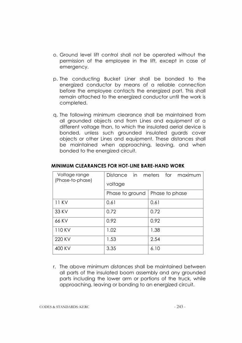
CODES & STANDARDS: KERC - 243 -
o. Ground level lift control shall not be operated without the
permission of the employee in the lift, except in case of
emergency.
p. The conducting Bucket Liner shall be bonded to the
energized conductor by means of a reliable connection
before the employee contacts the energized part. This shall
remain attached to the energized conductor until the work is
completed.
q. The following minimum clearance shall be maintained from
all grounded objects and from Lines and equipment at a
different voltage than, to which the insulated aerial device is
bonded, unless such grounded insulated guards cover
objects or other Lines and equipment. These distances shall
be maintained when approaching, leaving, and when
bonded to the energized circuit.
MINIMUM CLEARANCES FOR HOT-LINE BARE-HAND WORK
Voltage range
(Phase-to-phase) Distance in meters for maximum
voltage
Phase to ground Phase to phase
11 KV 0.61 0.61
33 KV 0.72 0.72
66 KV 0.92 0.92
110 KV 1.02 1.38
220 KV 1.53 2.54
400 KV 3.35 6.10
r. The above minimum distances shall be maintained between
all parts of the insulated boom assembly and any grounded
parts including the lower arm or portions of the truck, while
approaching, leaving or bonding to an energized circuit.
CODES & STANDARDS: KERC - 244 -
s. The above table shall be printed on a plate of durable non-
conducting material, mounted in the Buckets or its vicinity in
such a position that the same is clearly visible to the operator
of the boom. Insulated measuring sticks only shall be used to
verify the clearances.
t. During positioning the Bucket alongside an energized bushing
or an insulator string, the minimum Line-to-ground clearances
indicated in the above table must be maintained.
u. The use of Handlines between Buckets, booms, and ground is
prohibited.
v. No conducting material longer than 0.9 meter, other than the
jumpers of appropriate length, armor rods, and tools shall be
placed in the Bucket.
w. Non-conductive type Handlines may be used from Line to
ground only when the same is not supported from the Bucket.
x. The Bucket and the upper insulated boom shall not be over
stressed by attempting to lift or support weights in excess of
the manufacturer's rating.
2.30 Notwithstanding all the above, the recommendations of the
manufacturer of the Hot-Line equipment being used shall be
strictly followed.

CODES & STANDARDS: KERC - 245 -
SECTION 3
SAFETY TO WORKMEN IN ENERGIZED SUBSTATIONS
3.1 For carrying out the construction or maintenance work in an energized
Substation, appropriate authorization and the Line Clearance Permits
shall be obtained from the designated, authorized person before work
is started.
3.2 Before commencing the work, the protective equipment shall be checked
for satisfactory performance and precautions necessary for the safety
of the personnel shall be ensured.
3.3 Extraordinary caution shall be exercised in handling busbars, structures,
and equipment in the vicinity of the energized facilities.
3.4 No employee shall be permitted to approach or take any conductive
object without a suitable insulating handle closer to exposed energized
parts than shown in the table below:
Nominal Voltage
Range (KV) Minimum Working distance
11 0.60 mtr
33 0.75 mtr
66 0.91 mtr
110 1.02 mtr
220 1.53 mtr
400 3.35 mtr
3.5 The minimum working distance stated in the above table shall not be
normally violated. These clearances can be curtailed only under the
following conditions:

CODES & STANDARDS: KERC - 246 -
a. The employee is insulated or guarded from the energized part1
Or
b. The energized part insulated or guarded from him and other
conductive object is at a different potential,
Or
c. The employee is isolated, insulated, or guarded from any other
conductive object(s), as during Hot-Line bare handwork.
3.6 When it is necessary to de-energize the equipment or Lines for protection
of employees, the requirements of Clause.4 shall be complied with.
3.7 Barricades or barriers shall be installed to prevent accidental contact with
energized Lines or equipment. Where appropriate, signs indicating the
hazard shall be displayed near the barricade or barrier.
3.8 Only designated employees shall be permitted to work on equipment
under LCP or adjacent control panels and precaution shall be taken to
avoid accidental operation of relays or other protective devices due
to jamming, vibration, or improper wiring.
3.9 Designated employees shall at all times control the use of vehicles, gin
poles, cranes, and other equipment in restricted and hazardous areas.
3.10 All mobile cranes and derricks shall be effectively grounded when
being moved or operated in close proximity with energized Lines or
equipment. If this is not possible, the equipment shall be considered
energized.
3.11 When a Substation fence must be expanded or removed for
construction purposes, a temporary fence affording similar protection
when the site is unattended, shall be provided. Adequate
interconnection with ground shall be maintained between temporary
and permanent fences.
1 Gloves or gloves with sleeves for the rated voltage involved shall be considered insulation to
the employee from the energized part.

CODES & STANDARDS: KERC - 247 -
3.12 All gates in all the unattended Substations shall be locked when the
work is in progress.

CODES & STANDARDS: KERC - 248 -

CODES & STANDARDS: KERC 249
Karnataka Electricity Regulatory Commission
DISTRIBUTION CODE

CODES & STANDARDS: KERC 250

CODES & STANDARDS: KERC 251
DISTRIBUTION CODE
SECTION-1
INTRODUCTION
1.1 General
1.1.1 The Retail Supply License issued by KERC for any Company
requires the Licensee to formulate a "Distribution Code" for planning,
construction, operation and maintenance of the Distribution System to be
duly approved by the Karnataka Electricity Regulatory Commission
(KERC). The Distribution Code consists of the following:
(a) Distribution Planning Code containing the technical and design
criteria and procedures to be followed by the Licensee in the
planning and development of the Distribution & Retail Supply
Licensee's Distribution System; and
(b) Distribution Operation Code containing the conditions under which
the Distribution & Retail Supply Licensee shall operate his Distribution
System. This code also specifies the requirements necessary to
maintain the quality, security and safe operation of the system
under normal and abnormal conditions.
1.1.1 The Karnataka Electricity Regulatory Commission in exercise of the
powers conferred on it by Sections 11(j) and 56 of the KARNATAKA
ELECTRICITY REFORM ACT, 1999 has issued "Electricity Supply and
Distribution Code, 2000-01". This covers the distribution and supply of
electricity and procedures thereof such as the powers, functions and
obligations of the Licensees and the rights and obligations of the
consumers and all incidental matters connected therewith.
1.1.2 This "Distribution Code", hereinafter referred to as the Code covers the
following:
i. Distribution Planning Code,
ii. Distribution Operation Code.

CODES & STANDARDS: KERC 252
The Code also covers all the technical and operational aspects
pertaining to planning and development of the Distribution & Retail
Supply Licensee's Distribution System and use of the same by specific
Users connected or seeking connection to it. Further, the operation of
the Distribution System by the Distribution & Retail Supply Licensee,
operation of their own plant by the users (including Transmission
Licensee) are also covered in this Code.
1.1.3 The provisions of this Code are common to all the Distribution & Retail
Supply Licensees except in cases of specific deviations/departures or
approvals made to an individual Licensee by KERC.
1.2 Scope
1.2.1 The provisions of this code shall be applicable to the Distribution &
Retail Supply Licensee and to all the specific Users of the Licensee's
Distribution System excepting for any exemptions granted in writing by
KERC.
1.2.2 Further, the Distribution & Retail Supply Licensee and the consumers
seeking connection with the Distribution System shall comply with the
"Electricity Supply and Distribution Code, 2000 - 01".
1.3 Implementation and Review of the Distribution Code
1.3.1 The Distribution & Retail Supply Licensees shall periodically review this
Code and its implementation, as and when necessity arises. For this
purpose a Review Panel, hereinafter called Panel, shall be established.
The Panel shall consist of the following members:
a. A Chairman, on rotation basis, from each Distribution & Retail
Supply licensee;
b. One member from each of the Distribution & Retail Supply
Licensees;
c. One member from the Transmission Licensee;

CODES & STANDARDS: KERC 253
d. One member each from the Generating Stations directly
connected to each of the Distribution & Retail Supply Licensee's
Distribution System to represent all the Generating Stations,
e. One member to represent consumers to be nominated by
KERC.
1.3.2 The Panel shall frame, with the approval of KERC, its own Rules and
procedures for conducting its business, including appointment and
tenure of the Chairman, Convener and Secretary, a standing
Secretariat and appropriate funding arrangements for the Panel.
1.3.3 The Panel shall meet at least once in three months.
1.3.4 The Panel shall carry out the following functions:
a. Periodical Review of the Code and associated standards and
their implementation;
b. Review of all the suggestions for amendments to this Code
made by any of the Distribution & Retail Supply Licensees or other
members and also KERC;
c. Issue of guidelines in relation to this Code, and its
implementation, interpretation of any provision thereunder at the
request of any person connected to the Distribution & Retail Supply
Licensee's Distribution System;
d. Consider changes necessary in this Code arising out of any
unforeseen circumstances.
e. Review the causes of electrical accidents, if any, and remedial
measures to avoid recurrence of such accidents.
1.3.5 Following any such review made, the Secretary of the Panel shall
submit the following to the KERC:
a. A report on the outcome of any such review
b. Any proposed revision or revisions the Panel may reasonably
think fit for achieving the objectives of this Code;
c. All the written representations or objections from any member of
the Panel whose views were not accepted by the Panel.

CODES & STANDARDS: KERC 254
1.4 Unforeseen Circumstances
1.4.1 In the event any circumstance not envisaged in the provisions of this
Code arises, the Distribution & Retail Supply Licensee shall, to the
extent reasonably practicable, consult promptly in good faith with all
the affected Users in an effort to reach an agreement as to the further
course of action. If such an agreement cannot be reached within the
available time, the Distribution & Retail Supply Licensee shall follow a
prudent utility practice, keeping in view the nature of the unforeseen
circumstance and the technical parameters of the affected User's
System. Under such an event, the affected Users shall comply with the
instructions given by the Distribution & Retail Supply Licensee. The
concerned Distribution & Retail Supply Licensee shall however refer all
such cases for consideration in the next meeting of the Panel.
1.5 Non-Compliance
1.5.1 The Licence requires the Distribution & Retail Supply Licensee to
comply with the provisions of this Code. The Users are required to
comply with the provisions of this Code pertaining to them. Any User or
Distribution & Retail Supply Licensee to whom the provisions of this
Code apply, and for any reason unable to comply with the same, shall
promptly refer the matter to KERC, justifying his actions. The KERC may
grant exemption depending upon the merits of such matter. Non-
Compliance with the provisions of this Code without justifiable reasons
meriting exemption shall constitute an offence under the Act.

CODES & STANDARDS: KERC 255
SECTION 2
DEFINITIONS
In the Distribution Code the following words and expressions shall, unless the
subject matter or context otherwise requires or is inconsistent therewith, bear
the following meanings:
Act The Karnataka Electricity Reform Act, 1999
Active Power The product of voltage and the in-phase component of
alternating current measured in units of watts and standard
multiples thereof, i.e.,
1000 Watts = 1 KW
1000 KW = 1 MW
Agreement An Agreement entered into by the Licensee and the User.
Apparatus All the Electrical Apparatus, including machines, fittings,
accessories and appliances in which conductors are used.
Apparent Power The product of voltage and current of an alternating current
system measured in units of volt-amperes and standard
multiples thereof, i.e.,
1000 VA = 1 kVA
1000 kVA = 1 MVA
Area of Supply The area within which a Licensee is authorized by his License
to supply Electricity at the time.
Bare conductor Conductor not covered with insulation.
Breakdown An occurrence relating to an equipment of the supply system
or line, which prevents normal functioning.
Cable A length of conductor provided with insulation. The same
may or may not be provided with an overall mechanical
covering.
Circuit Arrangement of conductor(s) for the purpose of carrying
electrical energy and forming a system or branched system.
COINCIDENCE FACTOR Ratio of combined peak loads of a group of connected
loads to the sum of peak loads of the individual connected
loads.
Conductor Any Wire, cable, Bar, Tube, Plate, etc., used for conducting
energy and electrically connected to the system.
Connected Load Aggregate of manufacturer's rating of all the connected
Apparatus, including portable Apparatus, in the consumer's
premises. It includes all Apparatus for which the Consumer
has made declaration, for taking supply. This shall be
expressed in KW or KVA. If the ratings are in KVA, the same
may be converted to KW by multiplying the KVA with a
Power Factor of 0.85. If the same or any other Apparatus is
rated by the manufacturer in HP, the HP rating shall be
converted into KW by multiplying it by 0.746.

CODES & STANDARDS: KERC 256
CONNECTION POINT/
INTERCONNECTION
A point at which a User's electrical system is connected to
the Licensee's Distribution System.
Contract
Demand
Maximum KW or KVA agreed to be supplied by the Licensee
and indicated in the agreement executed between the
parties. Wherever the agreement stipulates supply in KVA,
the quantum in terms of KW may be obtained by multiplying
by the Power Factor of 0.85.
Control Person The person designated by the Distribution & Retail Supply
Licensee and any User having common electrical interface
with the Distribution & Retail Supply Licensee's Distribution
System, responsible for safety coordination.
DISTRIBUTION SYSTEM ‘Distribution System‘ means any system consisting mainly of
cables, service lines and overhead lines, electrical plant and
meters having design voltage of 33 KV and below. The
distribution system shall not include any part of a transmission
system except the terminal equipment used for the supply of
electricity to extra high voltage (66 KV and above)
consumers.
DIVERSITY FACTOR Ratio of the sum of peaks of group of connected loads to the
combined peak load of the group.
ESCOM Electricity Supply Company holding Distribution and Retail
Supply License.
Grid Code Karnataka Electricity Grid Code approved by KERC.
High Tension (HT) System or supply energized at 650 volts or above up to 33,000
volts.
KERC Karnataka Electricity Regulatory Commission.
KPTCL Karnataka Power Transmission Corporation Limited.
Load Factor Ratio of average load to peak load over a designated
period.
Low Tension (LT) System or supply energized at 415 Volts three phase or 240
Volts single phase.
Power Factor Ratio of Active Power to Apparent Power i.e. KW to KVA.
SLDC State Load Dispatch Centre.
TRANSMISSION SYSTEM The System consisting of extra high voltage lines and stations,
having design voltage of 66 KV and above owned or
operated by a Transmission Licensee for transmission of
electrical power from the generating station bus bars up to
the interconnection point with the distribution system. This
shall not include any part of the Distribution System.
User Any person having electrical interface with, or using the
Distribution System of the Distribution & Retail Supply Licensee
to whom this Code is applicable. Any other Distribution &

CODES & STANDARDS: KERC 257
Retail Supply Licensee, Transmission Licensee and generating
units connected to the Distribution system are also included
in this term.
The words or expressions occurring in this Code but not defined above shall
have the same meaning as in the Karnataka Electricity Reform Act, 1999; or
Indian Electricity Act, 1910; or the Electricity (Supply) Act, 1948; or in the Rules
and Regulations framed under the said Acts. In the absence thereof, the
meaning commonly understood in the electricity industry shall be applicable.
***

CODES & STANDARDS: KERC 258
SECTION 3
DISTRIBUTION PLANNING CODE
3.1 Scope
3.1.1 The Distribution Planning Code specifies the technical and design
criteria and procedures to be followed by the Distribution & Retail
Supply Licensee for a proper planning and development of the
Distribution System. This Code is also applicable to the Users of the
Distribution System for their planning and development in so far as they
affect the Distribution System.
3.1.2 The requirement of the Users may necessitate extension or
reinforcement of the Distribution System. In some cases the same may
even require the Licensee to seek the extension or reinforcement to
the capacity of the Transmission System at the connection point. This
may arise for a number of reasons mentioned below, but not limited to
the same:
(a) A development by any User in his system already connected to
the Distribution System;
(b) Introduction of a new connection point between the User's
System and the Licensee's System;
(c) To increase the capacity of the Distribution System for meeting
the security standards, removal of constraints in operation etc.,
and accommodate a general increase in Demand.
3.1.3 The development of the Distribution System must be planned
sufficiently in advance allowing for the required time to obtain the
required statutory clearances and consents or way leaves, and the
detailed engineering, design and construction work to be carried out
and completed. The management techniques such as PERT and CPM
shall be implemented allowing for sufficient slack time for critical
activities, to co-ordinate all the activities in an efficient manner. These
shall be taken care of at the time of planning itself.

CODES & STANDARDS: KERC 259
3.2 Objectives
3.2.1 The following are the objectives of the Distribution Planning Code:
(a) To enable the planning, design and construction of the Distribution System
for a safe and economical operation with the specified degree of
reliability conforming to the following standards:
i. Distribution System Planning and Security Standard,
ii. Distribution System Construction, Operation and Maintenance
Standard,
iii. Safety Standard for the Distribution System,
iv. Statutory Acts and Rules such as IE Act, IE Rules etc.
v. Relevant Indian Standard Specifications,
vi. REC Construction Standards and manuals.
(b) To facilitate the use of the Distribution System by any User connected to or
seeking connection with it,
(c) To formulate the technical conditions to be followed by the respective
Distribution & Retail Supply Licensees and Users in meeting the
standards for an efficient operation of the common electrical
interface,
(d) To formulate the procedure for the exchange of the system planning data
between the Distribution & Retail Supply Licensee and the Users,
(e) To provide the required information to the Users for connection, planning
and development of their own systems and make them compatible
with the Distribution System,
(f) To enable the Distribution & Retail Supply Licensee to co-operate with the
Transmission Licensee in furnishing the required data as detailed in the
Grid Code under the section "System Planning".
3.3 Load Data
3.3.1 The Distribution & Retail Supply Licensee shall develop load curves for
the area fed by the concerned substation of the Transmission Licensee
from the metering data available at the connection point. These data

CODES & STANDARDS: KERC 260
shall be compiled for the entire Area of Supply combining the load
curves of each substation feeding its Distribution System.
3.3.2 The actual energy drawn by the distribution system as recorded in the
energy meters installed at connection points shall be reconciled with
the actual energy sales. The distribution losses computed from these
data shall be furnished to the Transmission Licensee and KERC every
month.
3.3.3 All the Users with Demands of 5 MW and above seeking connection
shall furnish their load data to the Distribution & Retail Supply Licensee
as detailed in Annexe 1. The Distribution & Retail Supply Licensee shall
exercise special care to monitor the actual development of loads in
respect of consumers desiring to avail loads of 5 MW and above at a
single point. The Distribution & Retail Supply Licensee on his part shall
furnish relevant System data as detailed in Annexe 2, if required by the
User seeking connection to his Distribution System. The Distribution &
Retail Supply Licensee shall update the System data regularly and at
least once a year.
3.4 Forecast Methodology
3.4.1 The Distribution & Retail Supply Licensee shall formulate a long-term
demand forecast considering the previous financial year as base and
projecting the Demand for the succeeding 5 years. During this process
he shall review the status of loads materializing as per the previous load
forecast.
3.4.2 Energy sales in each Tariff Class shall be projected in the forecast
period over the corresponding figures relating to the base year by
adopting an appropriate statistical method.
3.4.3 The projections shall take into account the assumed normal growth for
non-specific loads, specific and identified loads of 1 MW and above,

CODES & STANDARDS: KERC 261
and the effects of Demand Side Management, if any, and energy
conservation.
3.4.4 The aggregate energy and peak load requirements at each
connection point shall be estimated taking into account the
distribution losses.
3.4.5 The Distribution & Retail Supply Licensee shall forward the long term
demand forecast for each connection point with the Transmission
System for his area of supply on annual basis to the Transmission
Licensee and KERC along with the following details on the basis of
which the forecast is made:
(a) Data,
(b) Methodology,
(c) Assumptions.
3.4.6 It shall be the responsibility of all the Distribution & Retail Supply
Licensees to fully co-operate with the Transmission Licensee in
preparation of demand forecasts for the entire Karnataka State.
3.5 Technical and Design Criteria:
The Distribution & Retail Supply Licensee shall plan and develop his
Distribution System on the basis of the following technical and design
criteria:
3.5.1 The load demand of all the existing Users connected to it and all Users
seeking connection with it shall be met. All the Apparatus and Circuits
shall have adequate capacity to cater to their needs of electricity in a
safe, economical and reliable manner.
3.5.2 The Distribution & Retail Supply Licensee shall assess and forecast the
load demand of each category of consumers in his area of supply on
annual basis or more frequently as required by the KERC.

CODES & STANDARDS: KERC 262
3.5.3 The Distribution & Retail Supply Licensee shall have a thorough
knowledge of the usage of electricity by the consumers and the way
they use electrical energy and other alternative sources of energy in
his area. The Load forecasting shall take into account all these along
with other conservation programs and the demand side management
or off-peak usage programs which the Licensee may sponsor, resulting
in reduction of energy and peak demand of the consumers over the
years.
3.5.4 The Distribution & Retail Supply Licensee shall implement an
appropriate load research program for the systematic collection of
data describing consumers' energy usage patterns and analysis of
these data for energy and demand forecast. For this purpose, the
consumers shall be divided into the following classes:
(a) Domestic sector,
(b) Commercial sector,
(c) Agricultural sector,
(d) Industrial sector
The pattern of energy consumed by each sector and the load
demand, the period of peak demand etc., shall be made on sample
surveys taking representative samples from each sector for its different
seasonal requirements. A suitable questionnaire shall be prepared for
these sample surveys and the data obtained shall be analyzed using
suitable statistical models. Based on this, load profiles shall be drawn
implementing Demand Side Management techniques to match the
availability from time to time.
3.5.5 The load research program shall assess the following:
i. Demand at the time of system peak, daily, monthly, seasonal or
annual,
ii. Hourly demand for the day of the system peak, monthly,
seasonal or annual,
iii. Category wise Diversity Factor or the Coincidence Factor and
Load Factor,

CODES & STANDARDS: KERC 263
iv. Total energy consumption for each category by day, month,
season or year,
v. Category wise non-coincident peak demand.
3.5.6 Based on the results of the above analysis the load forecast shall be
made using the appropriate modern forecasting tools wherever
applicable.
3.5.7 The optimum circuit loading and the maximum number of circuits at
any electrical interface between the Distribution and Transmission
Systems shall conform to the Distribution System Planning and Security
Standard, Distribution System Construction, Operation and
Maintenance Standard, and Safety Standards for Distribution System
issued separately. These standards form an integral part of this Code.
3.5.8 As far as practicable, separate circuits shall be provided for the
following:
i. Urban non-industrial power supply,
ii. Urban industrial power supply,
iii. Rural Supply.
3.5.9 The loads shall be arranged as far as possible in discrete load blocks to
facilitate load management during emergency operations.
3.5.10 Load Flow and other system studies shall be conducted to locate the
position of 33 / 11 KV substations, capacitor installations, distribution
transformers, and to contain voltage variation and energy losses within
reasonable limits.
3.5.11 The following parameters of equipments and system designs shall be
standardized to facilitate easy replacement and reduction of
inventories of spares in stores:
(a) Capacities of Power Transformers,
(b) Capacities and designs of Distribution Transformers,
(c) 33 KV substation Layouts,

CODES & STANDARDS: KERC 264
(d) Pole mounted substations,
(e) Sizes of Bus bars,
(f) Capacities and ratings of Circuit breakers and Instrument
Transformers,
(g) Earthing,
(h) Lightning Arresters,
(i) Control Panels,
(j) Station Batteries,
(k) Fire Extinguishers.
3.5.12 The planning of the Distribution System shall always keep in view the
cost effectiveness and reduction in energy losses without sacrificing
the requirements of Security Standards and Safety Standards for the
Distribution System mentioned in clause 3.5.7.
3.5.13 The Distribution & Retail Supply Licensee shall plan the Distribution
System expansion and reinforcement keeping the following in view
along with all other measures to accommodate the advancement in
technology prevailing at the time:
i. Economic Ratio of HT and LT line lengths,
ii. Use of Aerial Bunched Conductors,
iii. Underground Cables,
iv. Increasing the number of Distribution Transformers and their
location at the electrical load centers.
3.6 Planning Procedure
3.6.1 The Distribution & Retail Supply Licensee shall forecast the Demand for
power within his Area of Supply annually or more frequently as and
when directed by KERC, for each succeeding 5 years.
3.6.2 The Distribution & Retail Supply Licensee shall create a database of
loads for each consumer category and for each Distribution Substation
connected to the Distribution System and update it on annual basis.
3.6.3 The Distribution & Retail Supply Licensee shall work out the details of the
Load Research Program mentioned in clause 3.5.4 and file his proposal
with KERC for its consideration.

CODES & STANDARDS: KERC 265
3.7 Energy Audit
3.7.1 The Distribution & Retail Supply Licensee shall create responsibility
centers for energy audit. Divisions, cities and towns with population of
50,000 and above, shall be made as responsibility centers and
accountable for the energy sales and calculation of distribution losses.
Load survey meters with a memory retaining capacity of at least 45
days shall be installed for all the incoming/outgoing feeders in the area
identified for each such responsibility centre.
3.7.2 The Distribution & Retail Supply Licensee shall carry out energy audit of
his total system compiling the data and analysis carried out in each
responsibility centre. The energy received from each substation shall
be measured at the 11 KV terminal switchgear of all the outgoing
feeders installed with appropriate energy meters such that the energy
supplied to the each division is accurately available. It shall be
compared with the corresponding figures of monthly energy sales and
the distribution loss for each division shall be worked out.

CODES & STANDARDS: KERC 266
Annexe 1
LOAD DATA FOR DEMANDS OF 5 MW AND ABOVE
(Clause 3.3.3)
1. Type of Load:
(E.g. Furnace loads, rolling mills, traction loads, pumping loads, industrial
loads etc.)
2. Maximum Demand (KVA)
3. Year(s) by which full/part load supply is required:
(Phasing of loads shall be furnished)
4. Location of load with a location map drawn to scale:
5. Rated voltage, frequency and number of phases at which supply is
required:
6. Description of equipment:
a. Motors: (State the purpose and number of installations, voltage and KW
rating, method of starting, starting current and duration, type of motors, types
of drives and control equipments etc.)
b. Heating: (Type and KW rating)
c. Furnace: (Type, Furnace Transformer capacity and voltage ratio)
d. Electrolysis: (Purpose and KVA capacity)
e. Lighting: KW Demand.
f. Any other loads with particulars:
7. Sensitivity of Demand to fluctuations in voltage and frequency of supply at
the time of peak load: (Give details).
8. Phase unbalance imposed on the System:
Maximum:
Average:
9. Maximum harmonic content imposed on the System:
(Furnish details of devices proposed for the suppression of harmonics).
10. Details of the loads likely to cause demand fluctuations greater than 10
MW at the point of connection including voltage dips (percentage)
lasting for 5 seconds or more.

CODES & STANDARDS: KERC 267
Annexe 2
SYSTEM DATA
(Clause 3.3.3)
1. Topological map of Karnataka marking boundaries of Area of Supply of
the Licensee
2. Distribution map of the Distribution & Retail Supply Licensee drawn to scale
of not less than 1 cm to 2.5 KM showing the existing 11 KV and 33 KV lines
and substations within the Area of Supply of the Licensee. Lines and
substations under construction or planned for the next five years shall be
shown in dotted lines.
3. Single line diagram of the Distribution System showing line length,
conductor sizes, substation capacity, capacitor sizes with locations, auto-
reclosures etc.
4. Details of Metering and Relaying at 33/11 KV substations.
5. Details of Grid substations at the point of interconnections as follows:
i. MVA Capacity and voltage,
ii. Number of transformers, capacity of each transformer, voltage
ratios, Ranges of taps, Impedance
iii. Fault level at substation busbars, both three phase and single
line to ground fault
iv. Bus impedance,
v. Substation layout diagram.
6. Drawal at interconnection points: Maximum and Minimum MW drawal
from each interconnection with the Transmission System or with other
Distribution & Retail Supply Licensees during last six months.

CODES & STANDARDS: KERC 268
SECTION 4
DISTRIBUTION OPERATION CODE 4.1 Scope
4.1.1 This Section specifies the procedures and practices to be followed
for a safe and efficient operation of the Distribution System by the
Distribution & Retail Supply Licensee and by the Users of the Distribution
System of their electrical plant and lines which are connected to the
Distribution & Retail Supply Licensee's Distribution System. This shall also
apply to any electrical interface between two Retail Supply Licensees
for a safe and efficient operation of the interface.
4.1.2 The following aspects of operation are covered in this Section:
i. Demand Estimation,
ii. Outage Planning,
iii. Contingency Planning,
iv. Demand Management and Load Shedding,
v. Interface with small Generating Plant including CPPs,
vi. Metering and Protection,
vii. Communication,
viii. Monitoring and control of Voltage, Frequency and Power
Factor,
ix. Safety Co-ordination,
x. Major Incident and Accident reporting,
xi. Maintenance and Testing,
xii. Tools and Spares,
xiii. Training.
4.2 Demand Estimation
4.2.1 The Distribution & Retail Supply Licensee shall estimate his hourly and
daily Demands at each point of interconnection on the basis of
relevant Load Curves drawn on day-ahead basis subject to

CODES & STANDARDS: KERC 269
modifications depending upon the communications received from
any specific User or caused by any contingency.
4.2.2 For this purpose, the concerned major Users identified by the
Distribution & Retail Supply Licensee shall furnish the required data
pertaining to their Demands of their installations to him.
4.3 Outage Planning
4.3.1 The Distribution & Retail Supply Licensee shall furnish his proposed
outage programs to the Transmission Licensee on a month-ahead
basis.
4.3.2 The outage program shall contain identification of Lines and
Equipment of the Distribution System proposed to be taken out of
service, date of start of outage, duration of outage, quantum of load
restricted at any interconnection point during outage.
4.3.3 The outage plan proposed by the Licensee shall come into effect only
after the Transmission Licensee releases the finally agreed Transmission
outage plan.
4.3.4 However at the time the Line or Equipment is taken out of service, the
Distribution & Retail Supply Licensee shall intimate and obtain the
consent of the designated officer of the Transmission Licensee for the
same, even though the same is already included in the approved
plan.
4.3.5 In case of Lines and Equipments of 66 KV and above the specific
release of SLDC shall be obtained in addition to the above.
4.3.6 The above procedure shall not apply under the following
circumstances:
i. In cases where the estimated drawal at interconnection points
is not affected;

CODES & STANDARDS: KERC 270
ii. Emergency situations to save plant and machinery;
iii. In such of the unforeseen emergency situations requiring
isolation of Lines or Equipment to save human life,
iv. Disconnection to be effected on any User installation due to
violation of Agreement. In this case the SLDC shall be informed
wherever the load to the extent of 5 MW or more is affected.
4.3.7 Planned outages of Power System for more than 10 hours for
maintenance purposes shall be intimated to the public through media
two days in advance.
4.4 Contingency Planning
4.4.1 A contingency situation may arise in the event of a total or partial
blackout in the Transmission System. A contingency may also arise on a
part of the Distribution System due to local breakdowns in the
Distribution System itself. It may also arise due to a breakdown in the
Apparatus of the Transmission Licensee at the point of interconnection.
4.4.2 Transmission System Failure:
i. In case of a total blackout at any point of interconnection, the
Distribution & Retail Supply Licensee shall follow the black start
procedures framed by the Transmission Licensee as required in
the Grid Code.
ii. The Distribution & Retail Supply Licensee shall sectionalize the
Distribution System into discrete blocks of demand. He shall
advise the SLDC of the amount of MW load likely to be picked
up on switching each demand block.
iii. The Distribution & Retail Supply Licensee shall prepare a
schedule of essential and non-essential loads in order of priority
at each interconnection to be picked up during the restoration
process.
iv. The Distribution & Retail Supply Licensee shall ensure and
maintain the load generation balance under the direction of
the SLDC.

CODES & STANDARDS: KERC 271
v. The Distribution & Retail Supply Licensee shall maintain direct
communication links with the SLDC till normalcy is restored.
vi. The Distribution & Retail Supply Licensee shall furnish the names
and designations of the person(s) with their telephone numbers
and stations, authorized to deal with contingency operations, to
the SLDC.
4.4.3 Distribution System Failure:
i. Interruptions to power supply in any part of the Distribution
System lasting for more than two hours due to breakdown in any
part of the Distribution System may be termed as a Distribution
System Failure.
ii. The Distribution & Retail Supply Licensee shall evolve a
restoration process for such a Distribution System Failure.
4.4.4 Failure of the Apparatus of the Transmission Licensee:
i. The Distribution & Retail Supply Licensee shall immediately contact
the authorized person at the substation of the Transmission
Licensee, and assess the probable period of restoration and the
probable restriction of load drawal from the affected substation.
ii. The Distribution & Retail Supply Licensee shall effect the Demand
Side Management plan accordingly.
4.5 Demand Management and Load Shedding
4.5.1 Temporary Load Shedding may be resorted to for maintaining the
Load Generation balance as instructed by the SLDC. This may also be
necessary due to loss of any circuit or equipment or any other
operational contingency.
4.5.2 The Distribution & Retail Supply Licensee shall estimate Loads that
may be shed in discrete blocks at each Interconnection Point in
consultation with the Users supplied through independent circuits as
required. Such Users shall cooperate with the Licensee in this regard.
The Distribution & Retail Supply Licensee shall work out the sequence of
Load Shedding operations and the detailed procedure shall be
furnished to the persons in-charge of substations concerned where

CODES & STANDARDS: KERC 272
such Load Shedding has to be carried out. In case of automatic load
shedding through under frequency relays, the circuits and the amount
of Load to be interrupted with corresponding relay settings shall be
intimated to the SLDC and persons in charge of the substations of the
Distribution & Retail Supply Licensee as necessary.
4.5.3 If the duration of Load Shedding to any part of the Distribution
System exceeds 60 minutes, the public should be intimated promptly
through the media. The Consumers with Contract Demand of 1 MW
and above and the essential services such as Hospital, Public Water
Works etc. shall be intimated over the telephone wherever possible.
4.6 Interface with Small Generating Units including CPPs
4.6.1 If the Distribution & Retail Supply Licensee has an interface with any
generating unit including CPP and an Agreement for this purpose
exists, the Distribution & Retail Supply Licensee and the concerned
owner of the generating unit shall abide by the following provisions in
addition to the provisions contained in this Code as applicable to all
the Users:
i. Generating Units up to 3 MW:
a. The owner shall provide suitable protection at the interface to
protect his system from any damage due to normal and abnormal
conditions in the Distribution System.
b. If the Generator is an Induction Generator, the owner shall install
separate metering for the Reactive Load drawal, in addition to his
operational metering.
ii. Generating Units of 3 to 5 MW:
In addition to the above provisions applicable to the Generating
Units up to 5 MW, the Generating Company shall comply with the
provisions of the Grid Code also.

CODES & STANDARDS: KERC 273
4.7 Metering and Protection
4.7.1 Operational metering:
The minimum requirement of Operational Metering at the Distribution
System substations shall be as follows:
i. 33 KV/11 KV substations:
33 KV Bus Voltage
11 KV Bus Voltage
33 KV incoming/outgoing current in each phase and each
circuit
Power Transformer Primary and Secondary Currents in each
phase of every Transformer
11 KV outgoing feeder currents in each phase for each
feeder
Power Factor in each 11 KV feeder
Load survey meters having memory duration of at least 45
days for all the incoming and outgoing feeders (both 33 and
11 KV)
ii. User's system with Demand of 1 MW and above:
Voltage
Current
Load
Power Factor
4.7.2 Tariff and Commercial Metering:
(a) Tariff metering shall be provided at each point of interconnection
between the Distribution and Transmission Systems in accordance
with the Grid Code and the Transmission Services Agreement.
(b) Tariff metering shall be provided at the connection points between
the User's System and the Distribution System and shall be
governed by the provision in the Transmission Services Agreement.

CODES & STANDARDS: KERC 274
(c) All the meters, metering cubicles and testing procedures shall
conform to the relevant Indian Standard Specifications and Indian
Electricity Rules, 1956.
4.7.3 Measurement of energy import/export:
(a) The Distribution & Retail Supply Licensees shall install the following
meters for all of their sub-transmission lines connecting the
generating stations, and substations for the measurement of
energy import/export from each line, energy generated in
generating units and energy consumed in power stations and
substations:
Active energy import.
Active energy export.
Reactive energy import.
Reactive energy export.
(b) Each metering point associated with the determination of energy
exported or imported, between the Generating Companies,
Transmission Licensees Bulk Supply Licensees and Distribution &
Retail Supply Licensees shall be provided with both main and
check meters. The minimum standard of accuracy of these meters
shall be of accuracy class 0.2. These meters shall conform to the
relevant IEC or IS specifications.
(c) All the instrument transformers used in conjunction with
commercial (tariff) metering shall also be of accuracy class 0.2
and conform to the relevant IEC or IS specifications. The rating shall
be suitable for catering the burdens of lead wires and metering.
(d) Data collection shall be used to integrate impulses from meters
over each integration period as per agreement, store values, and
to transmit the same to the data collection system of the
Distribution & Retail Supply Licensee. Data shall be collected from
both the main and check metering schemes.
(e) Voltage failure relays shall be provided to initiate alarm on loss of
one or more phases of the voltage supply to the meter.
(f) Main and check meters shall be provided at all interconnection
points. All the meters shall be tested and calibrated according to
the guidelines provided in the relevant IEC/IS specifications at least
once a year and also whenever the difference in readings
between the main and check meters exceed 0.5%.

CODES & STANDARDS: KERC 275
(g) Records of these calibrations and tests shall be maintained for
reference.
(h) The Generating Companies, Transmission Licensees, Bulk Supply
Licensees and Distribution & Retail Supply Licensees shall formulate
and agree upon a procedure covering summation, collection and
processing of tariff meter readings at various interconnection sites
of their area. Whenever necessary, these procedures can be
revised.
(i) The ownership, responsibility of maintenance and testing of these
meters shall be as mutually agreed to between the Users and the
concerned Licensees.
4.7.4 Protection System:
(a) No item of electrical equipment shall be allowed to remain
connected to the system unless it is covered by the appropriate
protection aimed at reliability, selectivity, speed and sensitivity.
The Distribution & Retail Supply Licensees shall cooperate with
the Transmission Licensee to ensure correct and appropriate
settings of protection to achieve effective, discriminatory
isolation of faulty line/equipment within the time target
clearance specified by the Transmission Licensee.
(b) Protection settings shall not be altered, or protection bypassed
and/or disconnected without consultation and agreement of all
the affected Users. In case the protection has been bypassed
and/or disconnected by agreement due to any cause, the same
should be rectified and protection restored to normal condition
as quickly as possible. If agreement has not been reached, the
electrical equipments shall be isolated forthwith.
(c) The settings of protective relays for 33 KV and 11 KV lines shall be
such that a fault in any section does not affect the section
between the generating unit and the faulty section under all
conditions. The Transmission Licensee shall notify the initial settings
and any subsequent changes to the Users from time to time.
Routine checks on the performance of the protective relays shall
be conducted and any malfunction shall be noted and
corrected as soon as possible. Short circuit studies required for
deciding the relay settings shall be conducted by the Licensee
with the data collected from the Transmission Licensee and the
Users. Representatives of the Generating Companies,
Transmission Licensees and Distribution & Retail Supply Licensees
shall meet periodically to discuss such malfunctions, changes in

CODES & STANDARDS: KERC 276
the system configuration, if any, and possible revised settings of
relays.
(d) The Transmission Licensee shall be responsible for arranging
periodical meetings between the Generating Companies and
the Distribution & Retail Supply Licensees to discuss coordination
of protection. The Transmission Licensee shall investigate any
malfunction of protection or other unsatisfactory protection
issues. The concerned Licensees shall take prompt action to
correct any protection malfunction or other unsatisfactory
protection issue as discussed and agreed to in these periodical
meetings.
(e) All generating units and all associated electrical equipment of
the generating company connected to the Distribution System
shall be protected by adequate protection, as per C.B.I.P.
manual vide publication 274, so that the system does not suffer
due to any disturbances originating at the generating unit.
(f) 33 KV lines: -These lines shall have two over current and one
earth fault non-directional IDMT protection. It shall also have
instantaneous over current element.
(g) Distribution System: -For Power Transformers of HV class in the
Distribution System, differential protection shall be provided for 10
MVA and above along with backup time lag over current and
earth fault protection with directional feature for parallel
operation. Transformers of 1.6 MVA and above but less than 5
MVA shall be protected by time lag over current, earth fault and
instantaneous restricted earth fault relays. In addition, all power
transformers shall be provided with gas operated relays, winding
and oil temperature alarm and protection.
(h) Distribution lines: - All the 33 KV and 11 KV lines at connection
points shall be provided with a minimum of over current and
earth fault relays as follows:
i) Plain radial feeders: Non-directional time lag over current
and earth fault relays with suitable settings to obtain
discrimination between adjacent relay settings.
ii) Parallel/ring feeders: Directional time lag over current and
earth fault relay.
iii) Long feeders/transformer feeders: These feeders shall
incorporate a high set instantaneous element.

CODES & STANDARDS: KERC 277
4.8 Communication
4.8.1 Reliable communication links shall be established for exchange of
data, information and operating instructions between the Licensee,
Users with a Demand of 5 MW and above and the SLDC.
4.9 Voltage, Frequency and Power Factor Monitoring and Control
4.9.1 The Distribution & Retail Supply Licensee shall monitor the Voltage,
Frequency and Power Factors in the Distribution System at different
points at peak and off-peak hours and take reasonable measures for
improvement of the same in co-ordination with the Users with
Demand of 1 MW and above, and the Transmission Licensee.
4.9.2 The Distribution & Retail Supply Licensee shall take Power Factor
improvement measures at strategic points in the Distribution System
by carrying out System Studies and installing the required Reactive
Compensation Equipments.
4.9.3 The Voltage in the Distribution System may vary depending upon the
available generation, system demand, and the configuration of
Transmission and Distribution Systems at any time. Under normal
operating conditions the Licensee shall exercise proper voltage
management in the Distribution System beyond the point of
interconnection with the Transmission System to maintain Voltage at
all levels according to the quality of supply mentioned in the
"Distribution System Planning and Security Standard" issued separately.
The capacitors, wherever available in the 33 kV substations shall be
operated to maintain reactive compensation to be within
acceptable limits of power factor of at least 0.9 keeping the bus
voltage in view.

CODES & STANDARDS: KERC 278
4.9.4 Users having Loads with high harmonic content, low Power Factor
and fluctuations shall install appropriate correction Equipment.
4.9.5 The Distribution & Retail Supply Licensee shall abide by the instructions
issued by the SLDC from time to time on Load management for
maintaining the frequency of supply within the specified limits.

CODES & STANDARDS: KERC 279
4.10 Safety co-ordination
4.10.1 The Distribution & Retail Supply Licensee and the Users and any other
Distribution & Retail Supply Licensee having common electrical
interface with the Licensee shall designate suitable persons to be
responsible for safety co-ordination. These persons shall be referred to
as Control Persons. Their designations and telephone numbers shall be
exchanged between all the concerned persons. Any change in the
list shall be notified promptly to all the concerned.
4.10.2 The Distribution & Retail Supply Licensee and the Users shall prepare
safety manuals incorporating all the safety precautions to be taken
for each component of the Distribution System based on the "Safety
Standard for Distribution System" issued separately. All the safety rules
and precautions shall be observed when work is to be carried out on
any Line or Apparatus, switchgear or circuits in any part of the
Distribution System or in any part of the User System. The safety
manuals thus prepared shall be issued to all the control persons and
Users for compliance.
4.10.3 There shall be co-ordination between persons of the Distribution &
Retail Supply Licensee and the Users, between persons of two
Distribution & Retail Supply Licensees having electrical interfaces, for
carrying out the work on any Apparatus or Lines etc., belonging to
either party at the point of interconnection.
4.10.4 The provisions of the Grid Code shall be followed at interconnection
points in co-ordination with the Transmission Licensee.
4.10.5 The disconnecting device(s) at each electrical interface, which shall
be capable of effectively disconnecting the system of the Distribution
& Retail Supply Licensee and the other Users, and the grounding
devices of the respective systems at the control boundary shall be

CODES & STANDARDS: KERC 280
identified and marked by the Licensee and the respective Users.
These shall be maintained in good condition at all times. To prevent
inadvertent switching operations by unauthorized persons, such
disconnecting devices shall be provided with interlocks.
4.10.6 Wherever any Consumer has installed an emergency power supply
system, either an electronic system with storage batteries or with
generators, the arrangement shall be such that the same cannot be
operated without clearly isolating the system from the supply mains.
The possibility of a feed back from these devices to the Distribution
System from any of the conductors, including the neutral conductor
shall be clearly ruled out.
4.10.7 The appropriate control person at the electrical interface shall issue
written permission to his counterpart for carrying out the work on any
Apparatus, switchgear or lines beyond the electrical interface. Such
permissions shall be termed as "Line Clear Permits" (LCP). The format
for LCP shall be standardized by the Licensee and shall be used by all
concerned.
4.10.8 The Distribution & Retail Supply Licensee in consultation with the
concerned User shall frame checklist of operations to be carried out
and the procedures for safety coordination for each electrical
interface, before issue and return of LCPs. Such procedures and
checklists shall be issued to all the concerned by the Licensee for
implementation.
4.11 Major Incident or Accident Reporting
4.11.1 The Distribution and Retail Supply Licensee shall send a preliminary
report to KERC all the significant Incidents in the Licensee's Area of
Supply which results in interruption to service, substantial damage to
equipment or loss of life or significant injury to human beings within

CODES & STANDARDS: KERC 281
one week of its occurrence followed by a detailed report within one
month.
4.11.2 The Distribution & Retail Supply Licensee and the Users shall establish a
format and procedure for exchange of information.
4.11.3 The Users shall furnish information to the Distribution & Retail Supply
Licensee regarding any major incident occurring in their Systems
promptly.
4.12 Reporting Procedure
4.12.1 All reportable incidents occurring in the lines and equipments of 11 kV
and above at the 33 KV substations shall be promptly reported orally
by the Licensee whose equipment has experienced the incident, to
all other significantly affected Users identified by the Distribution &
Retail Supply Licensee and the Transmission Licensee. The reporting
Distribution & Retail Supply Licensee should submit a written report to
the Transmission Licensee within one hour of such oral report. If the
reporting incident is of major nature, the written report shall be
submitted within two hours duly followed by a comprehensive report
within 48 hours of the submission of the initial written report. In other
cases, the reporting Distribution & Retail Supply Licensee shall submit a
report within five working days to the Transmission Licensee.
4.12.2 The Transmission Licensee shall call for a report from any Distribution &
Retail Supply Licensee on any reportable incident affecting other
Users and in case such User whose equipment might have been a
source of the reportable incident does not report the same. However
this shall not relieve any User from the obligation to report Events in
accordance with IE Rules. The format for such a report shall be as per
the approval of the Distribution Code Review Panel and shall typically
contain the following:

CODES & STANDARDS: KERC 282
xiv. Location of the incident,
xv. Date and time of the incident,
xvi. Plant or Equipment involved,
xvii. Supplies interrupted and the duration wherever applicable,
xviii. Amount of Generation lost, wherever applicable,
xix. System Parameters before and after the incident,
(Voltage, Frequency, Load, Generation, etc.)
xx. Network configuration before the incident,
xxi. Relay indications and performance of protection,
xxii. Brief description of the incident,
xxiii. Estimated time of return to service,
xxiv. Any other relevant information,
xxv. Recommendations for future improvement,
xxvi. Name and designation of the reporting person.
4.12.3 The report shall contain sufficient detail to describe the Event to
enable the recipient to assess the implications and risks arising out of
the same. The recipient may ask for clarifications wherever necessary
and it is obligatory that the reporting User shall put his best efforts and
provide all the necessary and reasonable information.
4.12.4 In case of a request by either party, the oral report shall be written
down by the sender and dictated by way of a telephone message or
sent by Fax/e-mail to the recipient. In case of an emergency the
report can be given only orally and followed by written confirmation.
4.12.5 Reporting of accidents shall be in accordance with the IE Rules, 1956,
Rule 44-A. If an accident occurs in the Distribution System resulting in
or likely to have resulted in loss or injury to human or animal life, the
Distribution & Retail Supply Licensee shall send a telegraphic report to
the Electrical Inspector within 24 hours of the knowledge of such
occurrence. This shall be followed by a written report in the form

CODES & STANDARDS: KERC 283
setout in the Annexure XIII of I.E. Rules within 48 hours of the
knowledge of occurrence of fatal and all other accidents.
4.13 Maintenance and Testing
4.13.1 The Distribution & Retail Supply Licensee shall prepare maintenance
schedules for lines and equipment to meet the level of maintenance
as required in the "Distribution Construction Operation and
Maintenance Standard" and "Safety Standard for Distribution System"
issued separately along with the Performance Standard of the
Licensee.
4.13.2 Regular testing of all the equipments, such as Transformers,
Switchgear, Protective Relays etc., should be carried out as
recommended by the manufacturers and the relevant code of
practices issued by the Bureau of Indian Standards and CBIP. These
shall be carried out at the prescribed intervals and the test results shall
be recorded in the maintenance registers. Wherever the test results
indicate a decline in the insulation resistance and/or deterioration of
the Equipment, preventive maintenance shall be carried out to
ensure serviceability, safety and efficiency.
4.13.3 The Distribution & Retail Supply Licensee shall maintain well trained
hot-line personnel, and all the required tools in good condition, and
conduct the maintenance work by using hot-line technique,
wherever possible, to reduce the period of interruption.
4.13.4 The Users shall maintain their Apparatus and Power Lines at all times
conforming to I.E. Rules 1956 and shall be suitable for being
connected to the Distribution System in a safe and reliable manner.
4.14 Tools and Spares
4.14.1 The Distribution & Retail Supply Licensee shall ensure availability of
proper tools and tackles at all work places for carrying out the

CODES & STANDARDS: KERC 284
maintenance. The tools and tackles shall be checked from time to
time and their serviceability shall be ensured.
4.14.2 The Distribution & Retail Supply Licensee shall maintain an inventory of
spares required for maintenance and replacement purposes at
suitable locations according to a clear policy to be laid down by the
Licensee.
4.15 Training
4.15.1 The Distribution & Retail Supply Licensee shall make appropriate
arrangements for imparting training in both cold line and hot-line work
to his workmen and supervisory staff, incorporating up-to-date
techniques of Distribution System design, construction and
maintenance. He shall frame a suitable syllabus for this purpose.
***

CODES & STANDARDS: KERC 285
KARNATAKA ELECTRICITY REGULATORY COMMISSION
DPCOM – 1
DISTRIBUTION SYSTEM PLANNING AND SECURITY STANDARD
DPCOM – 2
DISTRIBUTION SYSTEM CONSTRUCTION, OPERATION AND MAINTENANCE
STANDARD
DPCOM – 3
SAFETY STANDARDS FOR DISTRIBUTION SYSTEM
DOS & DON’TS

CODES & STANDARDS: KERC 286

CODES & STANDARDS: KERC 287
DPCOM - 1
Distribution System Planning and Security Standard
1.0 Scope
1.1 This Standard specifies the guidelines for planning methodology of the
Distribution System. The system is to be planned by the Distribution &
Retail Supply Licensee in accordance with this standard read
together with the Distribution Code for providing the required
quality and reliability of power supply to the consumers and also to
meet the required safety requirements.
1.2 The Distribution & Retail Supply Licensee shall plan and develop the
Distribution System in accordance with this standard. The scope of
this standard covers the Distribution System comprising of Power
Lines and Substations from 33 KV down to 400/230 Volts. The Power
Lines and Substations of voltages higher than 33 KV are covered in
the Transmission System Planning and Security Standard.
2.0 Quality of power supply
2.0 Frequency: - The rated frequency shall be 50 Hz. All the constituents
of the Power System shall make all possible efforts to ensure that the
grid frequency remains within the bandwidth of 49.0 -50.5 Hz.
2.1 Voltage: -The highest and the lowest voltages given in the following
table shall be considered for design purposes:
AC Voltage Band as
per IS 123602
Preferred, Nominal
AC System Voltage
Highest System
Voltage
Lowest System
Voltage
2 As per the latest version of IS 12360 the preferred nominal phase to phase voltage in Voltage
Band II is 415 Volts. The present practice in Karnataka State is 400 Volts phase to phase and the
same is retained in the Electricity Supply and Distribution Code, 2000 - 01. The same shall
continue for some time till the change takes place to 415 Volts and falls in line with the rest of
the country.

CODES & STANDARDS: KERC 288
II Phase to Phase 400 V (415 V)* 440 V (457 V)* 360 V (374 V)*
II Phase to neutral 230 V (240 V)* 254 V (264 V)* 208 V (216 V)*
IIIA Phase to Phase 11 KV 12 KV 10 KV
33 KV 36 KV 30 KV
2.2 The voltage at any point of the system under normal operating
conditions shall not depart from the declared voltage by more than
the values given below:
Band II ± 6%
Band III A + 6% - 9%
2.3 Harmonic content: - As per IEEE recommendations, the total
harmonic content in the supply voltage for sensitive loads shall not
exceed 5 percent, with any single harmonic content not exceeding
3 percent.
3.0 Load Forecast:
3.1 The Distribution & Retail Supply Licensee shall prepare a rolling long- term
load forecast annually for a period of at least five years in his area of
supply duly estimating the probable load growth and the consumption
pattern of the consumers. The forecast thus made shall be updated
every year depending on the actual load that has come in that year
and the changes in assumption, if any, required for the next years.
3.2 Preliminary Load Survey:
3.2.1 Domestic and Commercial Loads: -
The consumption in Domestic and Commercial sectors shall be
estimated on the basis of the number of consumers and their specific
* Figures in brackets are as per IS 12360.

CODES & STANDARDS: KERC 289
consumption. The past growth rate in the number of consumers in the area
shall be studied. In cases where power shortages have been experienced in
the recent past, the growth rate to be adopted shall take into consideration
the pent-up demand making due allowance in the growth rate to account
for increased tempo of household electrification envisaged in the future. The
higher level of electrification planned in the area should be kept in view.
Energy consumption per consumer shall be estimated after studying the past
trends and taking into account the anticipated improvements in the standard
of living.
3.2.2 Public Lighting and Water Works
The estimates of electricity consumption in public lighting and water works
shall be based on the average consumption per kilowatt of connected load,
projected on the basis of trends, keeping in mind the likely increase in public
lighting and water supply facilities. The number of hours of operation shall be
estimated taking into account the past trends and the power cuts if any
effected in the area.
3.2.3 Agricultural Loads
The power requirement for Irrigation Pump sets shall be based on the
program of energisation of pump sets in the plan period, available resources
and the ultimate ground water potential. The average capacity of pump
sets shall be worked out considering the mid-year figures for connected load
and the number of pump sets. The consumption per IP set per year shall be
estimated by means of representative sample studies till all the IP sets are
metered.
3.2.4 Industrial Loads
The power requirements for industrial sector shall be estimated under three
categories, viz.
i. L.T. Industries;
ii. H.T. Industries with a demand of less than 1 MW;

CODES & STANDARDS: KERC 290
iii. H.T. Industries with a demand of 1 MW & above.
The consumption in category (i) & (ii) shall be on the basis of historical data
duly considering the developments in future. In case of category (iii),
projection shall be made separately for each industrial unit on the basis of
the information furnished by the industrialists and the Department of
Industries.
3.2.5 Non-industrial Bulk Supply
The available data regarding the consumption of bulk supply to non-
industrial consumers such as research establishments, port trusts, Military
Engineering Services, supply to power projects etc., and the probable future
developments in these areas, shall be considered for the forecast.
3.2.6 Other Loads
For other loads, the projections shall be based on the best
judgement.
3.3 Load Forecast procedure
3.3.1 Load forecasting methods using the above data and relevant indices
by adopting one or more of the following methods applicable to
specific locations and prevailing conditions shall be adopted.
Regression model;
Econometric model;
Strategic forecasting.
3.3.2 In addition to the above, the effects of Demand Side Management,
requirement of power for pending applications, the increase in
demand due to improvement in the operating frequency close to 50
Hz shall also be estimated. The Distribution & Retail Supply Licensee
shall work out the annual Energy Demand and Peak Demand for each
of the succeeding five years relating to each point of interconnection
with the Transmission System on the basis of Load forecast.

CODES & STANDARDS: KERC 291
3.3.3 The diversity factor of each category of consumers fed from each
point of interconnection in the area of supply shall be worked out by
installation of load survey meters at selected typical locations. A
record of such data shall be maintained and continuously updated.
The long-term load forecast for a period of five years, based on these
data shall be prepared.
3.3.4 The data book listing all system data relating to the Distribution System
shall be published. The data book shall be updated every year and
copies of the same shall be available to any person upon request, on
payment of fair copying charges.
4.0 Planning Procedure
4.1 The Distribution System shall be planned and developed in such a way
that the system should be capable of catering the requirement of all
categories of consumers with a safe, reliable, economical and quality
supply of electricity as indicated in clause 2.0. The Distribution System
shall conform to the statutory requirements of Indian Electricity Act
1910, Indian Electricity Supply Act 1948, Indian Electricity Rules 1956
and Karnataka Electricity Reforms Act 1999 as amended from time to
time.
5.0 Service Area of a distribution network
5.1 The service area of a distribution network is an area in which the load is
supplied by a substation by one or more number of feeders, as
required. The distribution network fed from the Distribution Transformers
and the Substations from which the 11 KV feeders emanate shall be
initially planned as independent networks within their respective
service area. Further, wherever possible, provision shall be made for
interconnection with adjacent networks and/or substations for an
alternate supply in case of failure. The design of distribution lines shall

CODES & STANDARDS: KERC 292
incorporate features to enable their augmentation in future, with
minimum interruption to power supply. The existing right of way shall be
fully exploited.
5.2 The Distribution & Retail Supply Licensee shall take suitable measures,
sufficiently in advance, to augment the capacity of the feeders in the
event the voltage regulation limit specified in CL 2.3 is exceeded within
the area.
5.3 Appropriate software to compute the design of the distribution network
shall be used to obtain lowest possible energy losses for different
loading conditions for the following:
(a) The location and the capacity of the distribution
transformers;
(b) Routing of LV and HV networks;
(c) The sizes of conductors;
(d) The ratio of the lengths of HT and LT distribution lines for
the new lines planned shall be around 1:1 and the
existing Distribution System shall be modified in a phased
manner to achieve this ratio.
(e) The voltage regulation limits for all loading conditions.
6.0 Planning Standards
6.1 Standardization of Sizes and Ratings
Adequate provision for future load development shall be made while
selecting the sizes of power conductors and rating of Distribution
Transformers. The sizes of Power Conductors, Insulators, Lightning
Arresters, Transformers, Switchgear, etc. used in the Distribution System
shall be standardized with the objective of reducing inventory and
standard specifications shall be prepared.

CODES & STANDARDS: KERC 293
6.2 Design Criteria for Distribution Lines
6.2.1 Radial system of distribution can be adopted in rural areas and loop
system with provision for feeding from atleast one alternate source shall
be adopted in urban areas.
6.2.2 The 11 KV and 400 V distribution lines shall be one of the following types
according to the necessity at the required area.
1. Over-head line with bare conductors;
2. Over-head line with Aerial Bunched Cables;
3. Under-ground Cables.
6.2.3 In thickly populated cities, in areas having heavy traffic densities,
Under Ground Cable installation shall be considered. Wherever a
number of trees are encountered, either in residential locations or in
gardens and forests, Over-head lines with Aerial Bunched Cables shall
be adopted. In other places Over-head lines with bare conductors
shall be adopted. The following standards shall be adopted for
planning and design purposes:
(a) The design and construction of over-head lines with bare
conductors shall be generally in accordance with IS 5613 Part I,
sections 1 and 2.
(b) Vertical configuration of conductors for LT distribution lines, to
prevent accidental short circuit due to galloping of conductors,
shall preferably be adopted in rural areas since the spans are
large in such areas.
(c) The maximum length of LT lines shall not exceed 0.5 KM and that
of 11 KV lines shall not exceed 20 KM and the total length of a
HT line with spur lines shall not exceed 50 KM subject to voltage
regulation limits. Irrespective of the size of the conductor used,
CODES & STANDARDS: KERC 294
the normal span between the supports shall be suitable for the
highest size of conductor adopted in the Distribution System for
the particular voltage. (At present "ACSR Rabbit" is the highest
size of power conductor used on LT and HT Lines in rural areas.
The highest size of power conductors used in urban areas is
"ACSR Coyote" for HT Lines and "ACSR Rabbit" for LT Lines. Till
such time any other higher size of conductor is introduced from
techno-economic considerations, the maximum spans
applicable for these conductors shall be adopted irrespective
of the size of conductor used.)
(d) The maximum length of 33 KV lines shall be limited to 30 KM
subject to voltage regulation limits. The minimum conductor size
shall be "ACSR Coyote"
(e) The design and construction of over-head lines with Aerial
Bunched Cables shall be generally in accordance with REC
Specifications 32 and IS 14255.
(f) The design and construction of under-ground cables shall be
generally in accordance with IS 1255.
6.2.4 The line supports can be of steel, wood, RCC or PCC. The RCC and
PCC poles are preferred over the other two considering their cost and
longer life. The minimum breaking strength of conductors shall not be
less than 350 KG. The choice of the size of conductor for a line shall be
made based on the following criteria:
a) Power to be transmitted and the techno-economic studies
conducted for selecting the size of the ACSR or AAAC
conductor according to the cost of loss of power and the
interest and depreciation charges on the cost of the conductor
thus selected;

CODES & STANDARDS: KERC 295
b) Length of Line;
c) Line Voltage;
d) Permissible voltage regulation;
e) Mechanical strength;
f) In coastal areas and other areas where severe corrosion is
expected due to heavy rainfall and/or salinity in atmosphere
and theft prone areas, All Aluminum Alloy Conductors (AAAC)
only shall be used.
g) The present use of ACSR conductor shall be gradually changed
to AAAC conductor.
7.0 Reliability Analysis
7.1 The planning of the extension and improvement to a Distribution
System shall also take into consideration the improvement in reliability
of power supply to consumers. The Reliability indices of power supply in
the area fed by the Distribution System before and after the
implementation of the extension and improvement program shall be
estimated. At present the information for the analysis of the reliability
limits under which the distribution system is being operated is not
available due to inadequate data. The planning of the distribution
system shall also take into consideration the improvement in reliability
and efforts should be made to collect the data in this regard.
7.2 The following reliability indices shall be computed:
I. Customer Average Interruption duration Index (CAIDI): - This index
is the average duration of an interruption of supply for a

CODES & STANDARDS: KERC 296
consumer, who experiences the interruptions of supply annually.
This index can be calculated for a station or a specified area as
follows:
(a) For the Transmission Licensee's Transmission Line failure:
Sum of product of number of consumers affected from
each feeder emanating from the stations in the service
area affected by the failure of the Transmission Line and
the duration of interruption to each of them
CAIDI= ------------------------------------------------------------------------------------
Total number of consumers in the service area
(b) For the Distribution Licensee's feeder failure:
Sum of product of number of consumers affected from
each feeder emanating from the stations affected in the
service area by the failure of power supply and the
duration of interruption to each of them
CAIDI= --------------------------------------------------------------------------------------------
Total number of consumers in the service area
II. System Average Interruption Frequency Index (SAIFI): - This index is
the average number of interruptions of supply that a consumer
experiences annually. This is calculated in the similar manner as
above except that instead of duration of interruptions, the number
of interruptions shall be used.
7.3 The following Factors, which affect reliability indices, shall be
considered subject to availability of data:
Momentary incoming supply failures
Momentary interruptions on 33 and 11 KV feeders
Breakdown on LT feeders

CODES & STANDARDS: KERC 297
Prearranged shutdowns on lines and feeders
Blowing out of Distribution Transformer fuses
Individual fuse off calls
8.0 Standardization of design of Distribution Transformers
8.1 The design of distribution transformers shall be standardized. As an initial
step, the various technical parameters required for the design shall be
incorporated in the specifications based on the experience on
performance gained among the various designs so far adopted. Later,
standard designs of the transformers and their detailed construction
drawings shall be evolved based on the performance of these
transformers. These shall be adopted for future procurement. This also
ensures the interchangeability of components of similar transformers
manufactured by any manufacturer.
8.2 A good quality assurance plan shall be aimed at the following:
(i) Good quality of raw materials;
(ii) Quality control during manufacturing and routine tests;
(iii) Acceptance tests at the time of taking delivery;
(iv) Inspection and tests on transformers received at stores on
random sampling;
(v) Strip test on one transformer in a lot selected at random. The
transformer should be completely dismantled. The quality of
core, coil, insulation etc physically inspected and samples of
insulation and other components used etc., tested.
9.0 Standardization of sub-station layouts
9.1 The Distribution & Retail Supply Licensee shall develop standard layouts
to fulfil the minimum requirements detailed below:

CODES & STANDARDS: KERC 298
(i) The layout shall generally be developed as per the requirements of
site and system conditions and the orientation of transmission and
distribution lines with scope for extension wherever necessary. The
bus bars and the minimum clearances adopted shall be as per the
following standards and manuals and the provisions of Indian
Electricity Rules, 1956.
1. BS 162 – Electrical power switchgear and associated
apparatus.
2. BS 159 – Bus bar and bus bar connections.
3. I.S. 3716 – Application guide for insulation co-ordination.
4. C.B.I.P. Manual on Substation Layouts.
5. R.E.C. Standards on 33 KV and 11 KV Substations.
The latest technology in the field and the feed back from the
experience gained shall be adopted.
(ii) 33/11KV Substation (10 MVA and above but less than 20 MVA)
The layout adopted shall include the following:
1. Independent circuit breaker control of 33 KV feeders and
transformers.
2. Independent circuit breaker control of each 11 KV feeder.
3. Sectionalized single bus.
(iii) 33/11 KV Substation (Less than 10 MVA)
The layout adopted shall include the following:
1. Group circuit breaker for transformers.
2. Independent circuit breaker control of 11 KV feeders.
3. Single bus.
(iv) 11 KV/ 400 V – 3 Phase Distribution Transformer centers.

CODES & STANDARDS: KERC 299
a. Transformers up to 250 KVA capacity other than those
meant for indoor application shall normally be pole
mounted.
b. The layout of distribution transformer centres shall generally
conform to relevant REC Construction Standards and the
provisions of Indian Electricity Rules, 1956.
c. The distribution transformers shall be located close to the
electrical load center of the loads fed by it as far as
possible.
d. The distribution transformers above 250 KVA shall be plinth
mounted.
e. MCCBs of suitable rating shall be provided on the
secondary side of the transformers above 100 KVA. Fuse
units of suitable rating shall be provided for transformers up
to and including 100 KVA. HRC fuses are to be provided
wherever the short circuit level is high.
f. Wherever the 400/230-Volt Distribution Lines pass through
thickly populated residential areas and roads with heavy
traffic, Earth Leakage Circuit Breakers of appropriate rating
shall be provided to the secondary circuits of the Distribution
Transformers.
g. Suitable measures shall be taken sufficiently in advance, to
augment the capacity of the feeders and installation of
additional transformer centers in the event the specified
voltage regulation limits are exceeded.

CODES & STANDARDS: KERC 300
9.2 All the 33 KV and 11 KV feeders shall be provided with load survey meters
having a memory capacity of 45 days, with 15/30 minutes interval
logging.
10.0 Reactive compensation
10.1 Shunt capacitors unswitched/switched type, shall be installed at the
appropriate places in the Distribution System for Power Factor
improvement, maintaining satisfactory voltage profile and reduction of
sub-transmission and Distribution Losses. The size and location of the
capacitor installations shall be determined using an appropriate
program, with reliable field data. Suitable precautionary measures,
such as automatic switching etc., shall be adopted to avoid over
voltages at light load periods.
10.2 Optimization studies of shunt compensation shall be conducted by the
Distribution & Retail Supply Licensee to determine the most appropriate
sizes and locations for shunt capacitor installations. The formulae to be
used in such studies, whenever done manually, are included in
Annexe-B.
11.0 Service mains
11.1 The service mains to consumers shall be laid in accordance with
relevant REC Construction Standards for 230 V single phase and 400 V
three phase supply and shall conform to the provisions of Indian
Electricity Rules, 1956 in all cases.
12.0 Metering Cubicles
12.1 The metering for 230 V single-phase supply shall be provided on a
suitable board, located in such a place protected from sun and rain

CODES & STANDARDS: KERC 301
and shall be in a convenient position for taking readings. The terminals
of the meter shall be made tamper-proof and sealed. For 400 Volts
three phase supply, the meters and associated metering equipment
including connections shall be enclosed in a suitable tamper-proof
box. The tamper-proof box shall be of sufficient strength and design
with locking and sealing devices and shall have adequate provision for
heat dissipation with the required electrical clearances. The design
shall permit readings to be taken without access to the meter or its
connections.
12.2 For HT Consumers the meters, maximum demand indicators, and
secondary connections, shall be housed in a separate compartment
and other secondary apparatus such as instrument transformers and
connections required shall be housed in a separate metering
compartment, which shall be locked / sealed to prevent tampering.
12.3 The HT metering cubicle shall be suitable for cable entry on both sides
or at least on one side. No fuses are permitted in the secondary circuits
of the instrument transformers. The metering cubicle shall be painted
with suitable epoxy paint for installation in coastal areas and other
areas experiencing heavy rainfall. The instrument transformers shall be
of fixed ratio and shall not have any taps. The primary current rating of
the current transformers shall match with the normal full load current
and the saturation point of the core shall be higher than the maximum
current that may occur due to simultaneous full load operation of all
the connected equipment and machinery.
12.4 For EHT consumers, the secondary terminals of the instrument
transformers shall be locked and sealed and the secondary wires
brought out in a suitable GI conduit pipe upto the metering panel.
There shall be no screwed joints in the pipes and the joints, if any, shall

CODES & STANDARDS: KERC 302
be welded. The meters shall be as close to the instrument transformers
as possible and in no case shall exceed ten (10) metres. The metering
panel shall be housed in a weatherproof and tamperproof box and
sealed.
13.0 Security Standards
The Retail Supply System shall be planned and maintained so as to
fulfill the following security standards except under Force Majeure
conditions beyond the reasonable control of the Distribution & Retail
Supply Licensee.
13.1 The feeders, either HT or LT, feeding important loads such as
Hospitals, Crematoria, Airports, Railway Stations, and the like shall be
planned to have a selective switching system, so that selective
switching can be operated to transfer the load on to an alternate
healthy feeder. Appropriate safety precautions shall invariably be
taken in this regard. In case of failure of the feeder, these switches shall
be operated immediately either manually or automatically depending
on the importance of the load.
13.2 The feeders connected to important industries like Information
Technology, primarily based on computer applications which are very
sensitive to interruption of even short duration shall be planned to have
automatic switchover to an alternate healthy feeder in case of failure
of supply.
13.3 Loading in any current carrying component of the Distribution
System (e.g. Conductors, joints, transformers, switchgear, cables and
other apparatus) shall not exceed 75% of their respective thermal limit.

CODES & STANDARDS: KERC 303
13.4 The rupturing capacity of the switchgear employed in the system
shall have at least 25% more capacity than the short circuit level
computed even considering the anticipated future development of
the system.
13.5 Provision shall be made to every feeder, either primary or
secondary, to manually switch over to the immediately available
feeder of the same voltage class available in the vicinity. Provision shall
be made in the design itself for any feeder to share at least 50% of the
loads in the adjacent feeder during emergencies.
13.6 In case of single contingency failure of any substation equipment
controlling any outgoing 11KV feeder, the load interrupted shall not
generally exceed 50% of the total demand on the substation. The
Distribution & Retail Supply Licensee has to bring it down to 20% within
a period of three years.
13.7 There shall be at least two number of transformers of similar rating in
every substation with secondary voltage of 11KV.
13.8 In every substation of capacity 10 MVA and above there shall be a
provision for obtaining alternate 33 KV supply to the substation in case
of a failure in the incoming supply.
13.9 The design of the Distribution System shall accommodate the
arrangements in such a way that the electricity supply need not be
interrupted for more than 24 hours in case of breakdown of any
distribution transformer. Similarly in case of failure of 11 KV feeders
including terminal equipment, the design shall accommodate an
arrangement for the power supply not to be interrupted for more than
24 hours.

CODES & STANDARDS: KERC 304
ANNEXE-A
Calculation of Power loss and Voltage drop.
The power loss and voltage drop of a short line may be calculated by the
following formulae:
Power Loss:
W= I² R
Where W = Power loss per km per conductor in watts,
I = Line current in amperes, and
R = ac resistance per km per conductor of the line in ohms.
Voltage Drop:
For single phase lines,
U = 2 ( IR Cos + IX Sin ) , and
For three-phase lines,
U = 3 ( IR Cos + IX Sin )
Where U = voltage drop per km in volts,
I = line current in amperes,
R = ac resistance per km per conductor of the line in ohms,
= Angle of lead/lag in degrees, and
X = reactance per km per conductor of the line in ohms.

CODES & STANDARDS: KERC 305
ANNEXE B
Rating of Capacitor required:
KVAR = KVA1 [Sin ø1 - (Cos ø1 / Cos ø2) Sin ø2]
Where KVAR = amount of capacitance to be added to improve the power
factor from Cos ø1 to Cos ø2.
KVA1 = Original KVA
Optimum location of capacitors:
L = [1 – (KVARC /2 KVARL)(2n-1)]
Where L= distance in per unit along the line from substation
KVARC = Size of capacitor bank
KVARL = KVAR loading of the line.
n = relative position of the capacitor bank along the feeder from substation if
the total capacitance is to be divided into more than one bank along the
line. If all capacitance is put in one bank then the value of n = 1.
Voltage rise due to capacitor installation
% Rise = KVARC. X / 10 V²
Where X = Reactance per phase
V = Phase to phase voltage in KV
***

CODES & STANDARDS: KERC 306

CODES & STANDARDS: KERC 307
DPCOM - 2
Distribution System Construction, Operation and Maintenance Standard
1.0 General
This standard is for the construction, operation and maintenance
of the Licensee‘s Distribution System to ensure safety, reliability
and efficiency with maximum security.
2.0 Construction practice
2.01 The construction of the distribution lines shall be carried out strictly as
per the following Indian Standards:
i) IS 7321 – Code of practice for selection, handling and erection of
concrete poles for overhead power and telecommunication lines.
ii) IS 5613 - Code of practice for design, installation and maintenance
of overhead power lines - Part 1 - Lines up to and including 11 KV -
Section 2 - Installation and maintenance.
iii) IS 5613 - Code of practice for design, installation and maintenance
of overhead power and telecommunication lines - Part 2 Lines
above 11 KV and up to and including 220 KV - Section 2-
Installation and maintenance.
iv) IS 1255 - Code of practice for installation and maintenance of
Power Cables (upto and including 33 KV).
v) IS 14255 - Aerial Bunched Cables for working voltages upto and
including 1100 Volts.
vi) REC Specification no 32 - Aerial Bunched Cables for working
voltage upto and including 1100 volts.
vii) IS-3043 Code of practice for earthing.
2.02 As mentioned in item (iii) above, the installation practices of Concrete
Poles for 33 KV lines shall be similar to that of 11 KV lines.

CODES & STANDARDS: KERC 308
2.03 The verticality of poles shall be maintained within reasonable limits of
tolerance by concreting of foundation from the bottom up to 150mm
above the planting depth in all the types of soil conditions at anchor
locations, cut points and transformer centers and all other locations
wherever necessary. These shall be suitably designed for the particular
soil condition and in any case shall not be less than 450mmx450mm
with a mix of ratio 1:2:4 commencing from the foot of the pole and
extending up to 150mm above the planting depth. In addition, it may
be desirable to concrete every fourth pole in non-cohesive soil.
2.04 After the poles are erected and soil back filled and well compacted
and after the first monsoon, the foundation shall be inspected and
back filled if necessary.
2.05 For LT lines, the conductors may be of horizontal configuration or
vertical configuration. Preference shall be given to vertical
configuration. The phase conductors in horizontal configuration should
be run on pin or shackle insulators. The neutral conductors may be run
on reel insulators. For vertical configuration, the insulators may be fixed
on the pole by use of D-type or other suitable clamps.
2.06 Wherever mid-span clashing of conductors is expected due to
excessive winds, uneven or excessive sagging, use of fairly longer
spans, etc., spacers conforming to REC standard 29 shall be invariably
used on LT lines. For tying the power conductors on pin insulators, the
top groove tie for tangent locations and the side groove tie for angle
locations conforming to REC construction standards C-3 and C-4 shall
be used. For dead end locations, strain insulator hardware consisting of
helically formed dead-end fitting, Cleves thimble and cross-arm strap
with bolts as per REC construction standard C-5 along with disc
insulators shall be used.

CODES & STANDARDS: KERC 309
2.07 The conductors of 11 KV and 33 KV lines shall be arranged in delta
formation generally by placing the top conductor on top of the pole
on an insulator with a bracket clamp and placing the bottom
conductors on insulators mounted on a suitable cross arm.
2.08 To provide for the possibility of conductor breakage in a street or
public place a continuous overhead earth wire is to be provided on
the poles along the line. Suitable V-guards or earth guard stirrups are to
be provided on each pole when the line runs along the street and
cradle guards are to be provided when the line runs across the street.
Should a line snap or fall down for whatever reason, it should make
contact with these earth guards and cause the overload device,
whether a fuse or a circuit breaker, to cut off the supply and render the
line harmless.
2.09 In case of horizontal configuration, the earth wire may be run on cast
iron knob mounted directly on the cross arm. For vertical configuration,
the earth wire may be run directly on the D-clamp.
2.10 Correct capacity fuses shall be provided and maintained in good
condition at all distribution transformer centers as per the following
table.
TABLE 1-Tinned Copper Fuse Wire Sizes for Pole Mounted Transformers.
Capacity of
Transformer
Current
Rating
11 KV side
Fuse Size
SWG
Current
Rating LT
Side
Fuse Size
SWG
25 KVA 1.31 amps 38 36 amps Protection Kits
up to 100 KVA
63 KVA 3.31 amps 35 91 amps
100 KVA 5.25 amps 33 144 amps
250 KVA 13.13 amps 23 360 amps 2 of 15
300 KVA 15.75 amps 23 433 amps MCCBs
250A-2 nos.

CODES & STANDARDS: KERC 310
500 KVA 26.24 amps 20 722 amps MCCBs
250A-4 Nos.
2.11 Spare fuses, of all the required sizes, shall be made available with all
the linemen in-charge of maintenance along with their toolkits and
these should be promptly replenished as and when they have been
used for replacement to avoid use of improper fuses by them.
2.12 The cross-arms shall be permanently and efficiently earthed. The
continuous earth wire shall be securely clamped to each support and
connected with earth at four points in every KM. The mechanical
connectors of line-traps at the conductor end of the earth connection
should be solidly bolted down to the metal parts of the cross arms and
supports using suitable washers after the surface has been emeried to
remove all rust and paint.
2.13 It is not enough to have a good earth connection initially at the time of
erection of the line, but it should also be maintained properly.
2.14 Each stay wire shall be similarly earthed unless an insulator has been
inserted in it at the top.
2.15 Earthing shall be in accordance with IS 3043 Code of practice for
earthing. The minimum length of ground electrode shall be 2500 mm.
The diameter of the ground electrode shall be at least 40 mm for GI
pipes or 20 mm for GI rods as per REC Construction Standards J-2. In all
33 KV substations, only cast iron pipes shall be used for earth
electrodes.
2.16 The following table specifies the minimum size of earth wires to be used
for earthing of the neutral point of the Distribution transformers:

CODES & STANDARDS: KERC 311
TABLE 2
Transformer
Rating.
Insulated PVC single core stranded
aluminum conductor.
50 KVA and
below
16 sq.mm.
75 KVA 25 sq.mm.
100 KVA 35 sq.mm.
150 KVA 70 sq.mm
200 KVA 95 sq.mm.
250 KVA 150 sq.mm.
300 KVA 225 sq.mm.
500 KVA 300 sq.mm.
2.17 The following table specifies the minimum size of earth lead to be used
for equipment earthing, such as transformers, motors, generators,
switchgear etc.
TABLE 3
Rating of 400 V
3 phase 50 Hz
equipment in KVA.
Size of PVC insulated Aluminum
earthing conductor.
Up to 5 6 sq.mm.
6 to 15 16 sq.mm.
16 to 50 16 sq.mm.
51 to 75 25 sq.mm.
76 to 100 35 sq.mm.
101 to 125 50 sq.mm.
126 to 150 70 sq.mm.
151 to 200 70 sq.mm.
201 and above 185 sq.mm.
2.18 The voltage gradient at the earth electrode at the transformer center
may attain sufficiently high value during heavy flow of ground currents
and become dangerous to cattle and human life. To eliminate the
possibility of danger, the top of the earth electrode shall be buried

CODES & STANDARDS: KERC 312
below earth surface and the connecting lead should be insulated. The
top of the earth electrode shall be at least 300 mm below the surface
of the soil as per clause 11.2 of IS 30433.
TABLE 4
3 It should be noted that the maximum voltage gradient over a span of 2 meters adjacent to a 25 mm
diameter electrode is reduced from 85% of the total electrode potential when the top is at ground level to
20 and 5 percent when it is buried at 0.3 and 1.0 meter respectively.

CODES & STANDARDS: KERC 313
2.19 Earth electrodes, other than those used for earthing of the fence itself,
should not be installed in the proximity of the metal fence, to avoid the
possibility of the fence becoming live and thus rendering it dangerous.
4 The clearances indicated in the IE Rules have been increased to have better safety margin in view of the
large number of accidents taking place. In case these clearances cannot be maintained, Ariel Bunched
Cables shall be used.
* The figures indicated in brackets are as per IE Rules.
Sl.N
o.
Particulars For LT
lines(Mtr
)
For 11 KV
Lines (Mtr)
For 33
KV
Lines
(Mtr)
a) Minimum height of
any conductor of an
overhead line across
any street.
5.8 6.1 6.4
b) Minimum height of
any conductor of an
overhead line along
any street.
5.5 5.8 6.1
c)
Minimum height of
any conductor (bare)
of an overhead line
erected elsewhere.
4.6 4.6 5.2
d) Minimum height of
any insulated
conductor of an
overhead line erected
elsewhere.
4.0 4.0 4.0
e) Minimum clearance
of overhead
conductor from
buildings.4
3.5 (2.5)*
(vertical)
1.8 (1.2)*
(horizont
al)
4.5(3.7)*
(vertical)
1.8(1.2)*
(horizonta
l)
4.5(3.7)
*
(vertica
l)
2.5(2.0)
*
(horizon
tal)

CODES & STANDARDS: KERC 314
2.20 The street lighting posts with underground cables require a great deal
of attention due to the fact that many times these cables are
connected at lower levels to the insulated wires coming from street
lights. A fuse box for the phase wire shall be fitted and properly
maintained at these connections. The fuse box shall be provided with
a hinged door, which shall be kept closed and locked from access to
public and shall be periodically inspected and maintained. It is
preferable that these fuse boxes are provided at an inaccessible
height.
2.21 The pole mounted distribution transformers shall not be accessible to
the public easily. Danger boards shall be invariably provided.
2.22 Suitable Danger boards and anti-climbing devices shall be provided
on the poles at locations accessible for human approach such as
school premises, market places etc.
2.23 The maximum span along any street in towns and cities shall not be
more than 40 meters. In road crossings, the poles shall be installed on
either side of the road and suitable guarding shall be provided.
2.24 The minimum clearances from any conductor of an overhead line from
ground and buildings at different places shall be maintained is indicted
in Table 4. These clearances are the minimum clearances at the lowest
point; i.e. at mid span under worst conditions, i.e. when sag is
maximum at highest conductor temperature. In actual practice,
however, it is preferable to allow a further safety margin of 0.6 meters.
2.25 Bare wires shall not be terminated on a building.
2.26 A tapping can be made only at the point of support. To ensure good
contact, only good quality connectors, preferably crimped connectors
shall only be used. Twisted joints shall be avoided.

CODES & STANDARDS: KERC 315
2.27 Fuses along with isolators shall be provided to isolate different parts of
the distribution system. Lightning arresters shall be provided on the 11
KV and 33 KV lines at places where the lines terminate for connections
to the equipments.
2.28 The entire pedestal mounted equipment such as distribution
transformers, switchgear, and distribution boxes etc. installed in streets
and accessible to public shall be protected by locking the doors
and/or providing a suitable fence with gate wherever possible.
―DANGER‖ Boards shall be prominently displayed on the fence and
equipment.
2.29 For the safety of telecommunication lines at locations where the
overhead power line may cross over the same, the recommendations
laid down in the code of practice of the Power and
Telecommunication Co-ordination Committee shall be followed. The
detailed drawing of the arrangement at crossings with
telecommunication lines as furnished in REC standards J4 and J5 shall
be followed.
2.30 When erecting overhead power lines, the conductors of the same shall
wherever possible, be arranged to cross over (not below) the existing
telephone or telegraph lines. For any special cases where it would not
be convenient or economical to remove the existing telephone or
telegraph them wires and erect below the power wires, special
guarding arrangements of suitable design shall be provided.
Where a telephone or telegraph line passes under a high voltage
aerial line on suspension insulators, the protective guarding
arrangements shall not be erected using the power line supports. A
separate guard shall be located not less than two meters above the
telephone or the telegraph line. This shall consist of two horizontal

CODES & STANDARDS: KERC 316
stranded solid galvanized steel conductors with additional horizontal
conductors at the sides where necessary to prevent a broken power
conductor from coming into contact with the telephone or telegraph
line conductor. This arrangement shall be made in such a way that the
broken power conductor is earthed for sufficient duration and ensure
the power circuit being tripped out by automatic protective devices.
The crossing of telephone or telegraph lines under power lines shall be
as nearly as possible at right angles.
3.0 Operational Criteria
The operational Criteria comprise of:
1. Load monitoring
2. Load balancing
3. Voltage monitoring and control
4. Data logging
5. Load management
6. Communication
7. Safety coordination
4.0 Load monitoring
4.1 Station Log Sheets and Registers for Station operations duly
recording the hourly readings of the meters such as current, load,
voltage etc., and the station operations shall be maintained at
each station. A separate register for the daily energy meter
readings for both the energy received and energy sent out shall
be maintained along with the above.
5.0 Load balancing
5.1 The unbalanced load on the LT side of the distribution transformers
shall not exceed 10% of the peak load.

CODES & STANDARDS: KERC 317
5.2 The secondary currents and voltages of the distribution
transformers shall be recorded at least once a month during
expected peak load hours on all the phases.
6.0 Voltage monitoring and control
6.1 The Voltage monitoring at each substation feeding 11 KV
distribution system shall be carried out by data logging.
6.2 The Voltage monitoring on the LT side of the distribution
transformers shall be carried out at least once a week during peak
load hours to cover at least two numbers of transformers in each
11 KV feeder as follows:
(a) One Transformer at the beginning of the feeder.
(b) One Transformer at the tail end of the feeder.
6.3 Improvement to voltage conditions shall be achieved by
operating OLTC wherever available in 33 /11 KV substations and
by contacting over telephone the operators of Transmission
Licensee at the point of interconnection, to correct Voltage at the
sending end whenever required.
7.0 Data Logging
7.1 All-important data such as Voltage, Current, Power factor, KW,
Transformer data such as tap position, oil/winding temperature,
etc shall be logged on hourly basis in all substations feeding
distribution lines.
7.2 The following records among others shall be maintained at each
station:
a) Operation and maintenance manuals for the equipment and the
entire station consisting of the details of operation of the station
and maintenance of equipment,

CODES & STANDARDS: KERC 318
b) Maintenance registers for the equipments and station batteries,
c) Interruption Registers,
d) Line Clearance Register,
e) Equipment registers.
7.3 A detailed analysis of the above data shall be made to assess the
performance of the equipments, overloading conditions and the
necessity for major maintenance.
8.0 Load management
8.1 In the event of total or partial black outs of transmission system or
regional system, the Distribution & Retail Supply Licensee shall
follow procedures as laid down in the DISTRIBUTION CODE for
restoring normalcy.
8.2 In the event of break down within its own system, the Distribution
and Retail Supply Licensee shall restore/ maintain supply within the
limits specified in the security standards by taking appropriate
measures.
9.0 Communication
9.1 The Distribution & Retail Supply Licensee shall establish reliable
communication facilities such as Fax, E-mail, etc., at major
substations. All operating instructions, messages and data
received from or sent to the concerned grid substations and Load
Dispatch Centers shall be duly recorded at the substations.
10.0 Safety coordination
10.1 The Distribution & Retail Supply Licensee and the consumers shall
abide by the general safety requirements of the Indian Electricity
Rules, 1956 for construction, installation, protection, operation and

CODES & STANDARDS: KERC 319
maintenance of electric supply lines and apparatus, and the
procedures laid down in the relevant DISTRIBUTION CODE. The
Distribution & Retail Supply Licensee and the consumers shall also
follow the Safety Standards for Distribution System issued
separately.
10.2 The Distribution & Retail Supply Licensee and the consumers shall abide
by the provisions of I.E.Rules, 1956 under Chapter VII ―Electric supply
lines, Systems and Apparatus for high and extra high voltages.‖
10.3 The Distribution & Retail Supply Licensee shall develop safety
manuals to meet the safety standards issued.
11.0 Maintenance
11.1 The Distribution & Retail Supply Licensee, for the guidance of the
operation and maintenance staff shall prepare suitable
maintenance manuals and programs for the various components
of the distribution system. Proper records shall be kept duly
updating the maintenance work done as per schedule, the details
of faults, malfunctions etc., encountered in the lines and
equipment during the period, the remedial action taken, etc., for
each component of the distribution system.
11.2 The following pre-requisites shall be first ensured for the satisfactory
maintenance:
a. The ability of the system to meet the probable over-loading due
to transfer of loads from the adjacent systems during
emergencies.
b. The quality of the materials used.

CODES & STANDARDS: KERC 320
c. Trained and adequately equipped maintenance staff.
d. Schedule of maintenance for each component of the system.
11.3 The maintenance work shall consist of routine inspection, cleaning,
testing and adjustments, if any required and is different from the
work carried out after a break down of any equipment in service,
for restoring the same to the working condition, which cannot be
planned in advance.
11.4 The maintenance schedules drawn shall cover the following:
i. Inspection
ii. Preventive maintenance
iii. Overhauls
11.5 Inspection
This shall include the periodical inspection in service for a check on the
condition of the equipments/lines in service to verify the faults and
defects that may develop during its operation so that advance action
can be taken to rectify the defects in a planned manner and prevent
breakdowns.
11.6 Preventive maintenance
This shall cover the periodical work including tests required to
determine the electrical and mechanical strengths to ascertain the
suitability in service and ensure proper working condition. The schedule
drawn shall be on the basis of data obtained from inspection and
maintenance checks, giving priority to the troubles encountered
during normal operation of the line or equipment.
11.7 Overhauls

CODES & STANDARDS: KERC 321
This shall cover the preventive maintenance work to be done on the
equipment based on the past experience and manufacturers'
recommendations and involves major disassembly of the equipments.
The schedule drawn shall be based on the normal life expectancy of
the equipment or data obtained from inspection and maintenance
checks.
The maintenance schedules shall be drawn for all the following
components of the distribution system separately:
i. Power transformers and distribution transformers of 500 KVA and
above.
ii. Pole mounted distribution transformers and capacitors.
iii. 33 and 11 KV circuit breakers along with all the associated
switchgear.
iv. LT circuit breakers.
v. Pole mounted auto-reclosers.
vi. 33 and 11 KV distribution lines including G.O.S.
vii. LT lines including switches and fuses.
viii. Service connections.
11.8 Effective maintenance work shall be ensured keeping the
following guidelines for the efficient working of the distribution

CODES & STANDARDS: KERC 322
system and for preventing accidents that may arise due to failure
of any of the components.
1. The distribution lines shall be inspected thoroughly before and after
the rainy season.
2. The defects noticed during inspection should be rectified at the
time of inspection itself if they are of minor nature, whenever and
wherever possible. In case of such of the defects, which cannot be
rectified easily, the same have to be attended to at the earliest
possible occasion duly chalking out a program in advance.
3. If abnormal conditions such as excessive heating or arcing or
prohibitively low clearances etc., are observed, the equipment or
the line shall be immediately disconnected and rectification of
defects carried out.
4. Manufacturers' instructions shall always be given due consideration
and implemented.
5. A continuous record of all the test results shall be maintained.
6. Appropriate inspection/maintenance checks/history sheets shall be
maintained containing details of all inspection and maintenance
work done.
7. All the required safety precautions/safety devices shall be used
while carrying out the maintenance works.
8. The maintenance schedule shall be periodically reviewed by the
Distribution and Retail Supply Licensee in the light of previous
experience and updated to include all possible improvements

CODES & STANDARDS: KERC 323
required for ensuring adequate maintenance, prevention of
accidents and reduction in interruptions.
11.9 Off-schedule inspections
Inspections of the following nature shall be carried out to maintain the
system at the required level of reliability in operation.
i. Special inspections:
These shall be made immediately after severe weather
conditions, such as heavy windstorms, thunderstorms and rains
to detect any damage or breakage of poles, insulators,
conductors and/or equipment, and necessary action taken.
ii. Emergency inspections: These shall be carried out on a line
during its breakdown, to locate and identify the cause of
trouble as early as possible in order to restore the power supply.
iii. Follow up inspections: Whenever one or more short time
interruptions are noticed which may have taken place due to
temporary faults, the inspection shall be carried out to locate
and identify the cause of interruptions and suitable
maintenance action shall be taken whenever and wherever
necessary.
iv. Check inspections: The designated engineer in charge of the
distribution system shall make these inspections periodically as a
check on the conditions of the line and equipment and the
efficacy of maintenance. He shall point out such defects, which
might not have been noticed by the maintenance staff in the
first instance.
*******

CODES & STANDARDS: KERC 324

CODES & STANDARDS: KERC 325
DPCOM - 3
SAFETY STANDARDS FOR DISTRIBUTION SYSTEM
1.0 Scope
1.1 This standard aims at ensuring safety for the general public from
the hazards of electric shock, which may be caused in the
Distribution System. The Distribution & Retail Supply Licensee shall

CODES & STANDARDS: KERC 326
prepare his own Safety Manual based on these standards for his
internal use. The Safety Manual shall be prepared in such a way
that all the required aspects and safety procedures to be
followed are covered in a complete manner without inviting
reference to any other codes or standards. The Safety Manual
shall also laydown foolproof procedure for issue of necessary
permits and clearances to the Engineer in charge of construction
and/or maintenance seeking such permits. The designated
employees for each substation or sub-transmission/distribution line
authorized to issue and receive such permits shall be notified from
time to time.
1.2 Reporting of Accidents: Every case where a person receives an
electric shock, whether mild or serious or suffers an injury or burn,
directly or indirectly due to electrical causes should be treated as
an “electrical accident”. The concerned jurisdictional engineer
of the Distribution & Retail Supply Licensee shall report the same
immediately to the Deputy Electrical Inspector in charge of the
area within 24 hours. A copy shall also be sent to the Chief
Electrical Inspector to the Government of Karnataka. The
designated officer of the Electrical Inspectorate should reach the
spot immediately and assess the situation and probable cause of
the accident, losses if any to consumers, and the equipment of
the Licensee. This should be followed by a detailed report within
48 hours whenever an accident occurs resulting in or likely to
have resulted in loss of life of a human being or an animal. The
Distribution & Retail Supply Licensee and the Electrical Inspector
shall take all other statutorily required actions, such as reporting
to the police etc.
CODES & STANDARDS: KERC 327
1.3 An enquiry should be conducted into every electrical accident. It
should be completed with the least possible delay, in any case,
not exceeding fifteen days to guard against the possibility of
destruction or disappearance of material evidence being
presented, to escape responsibility. It should be a searching
probe to uncover the root causes of the accident, which some
times are quite difficult to ascertain. The enquiry should not only
fix responsibility for the accident, but it is more important, to spell
out steps to be taken to prevent such accidents in future.
2.0 Safety to general public
2.0 Accidents can occur in the Distribution System due to the
following causes, which may result in injury to public.
a) Failure of Distribution line supports either due to sub-standard
quality or improper erection.
b) Snapping of overhead bare conductors.
c) Improper earthing at Distribution Transformer centers and of the
earth wire at certain line supports along the Distribution lines.
d) Inadequate clearances between overhead conductors and
ground or buildings.
e) Non-observance of Safety Rules, and abuse of the components of
the Distribution System.
2.1 The guidelines indicated in this section, if adhered to, will minimize
accidents in the Distribution system and ensure safety to public to
the maximum extent possible.
3.0 Actions by Licensee
3.1 The construction and maintenance of the distribution lines shall be
strictly carried out as per the "Distribution System Construction,
Operation and Maintenance Standard" issued separately. The
accidents can be minimized if the construction and maintenance of

CODES & STANDARDS: KERC 328
the Distribution System is carried out in accordance with the
"Distribution System Construction, Operation and Maintenance
Standard" issued separately. Wherever the existing System does not
meet any of the requirements of this standard, the same should be
rectified to meet the requirements of this standard, in a phased
manner within a specified time.
3.2 As far as practicable the pole mounted transformers shall not be
located near market places, schools and such premises of public
congregation.
3.3 Wherever the Distribution Transformers are installed indoors and/or in
restricted places susceptible for fire hazards, dry type transformers shall
be installed to prevent spreading of fire. For the same reasons, Oil
Circuit Breakers shall not be used in such places.
3.4 All the equipment and conductors shall have sufficient rating to carry
the estimated maximum load currents continuously and also short
circuit currents. They shall have sufficient mechanical strength required
for the duty, which they may be required to perform under the
environmental conditions of installation, and shall be constructed,
installed, protected, worked and maintained in such a manner as to
ensure safety to human beings, animals and property.
3.5 The following precautions shall be taken by the Distribution & Retail
Supply Licensee, wherever the electrical equipments of the Distribution
System are installed in public places, along or across the roads and
other places accessible to the public:
(a) The equipments, such as Distribution Transformer centers, Circuit
Breakers etc., shall be provided with barricades.
(b) The live parts shall not be easily accessible to the public.

CODES & STANDARDS: KERC 329
(c) The grounding provided for the equipment and Lines shall be in
accordance with IS 3043 - Code of Practice for Earthing. The
earth resistance shall not exceed 10 ohms. It is not enough to
have a good earth connection at the time of construction, but it
should also be maintained in a sound and healthy state at all
times. The earth wires and the earth electrodes provided in the
Distribution System shall be maintained in good condition to
ensure instantaneous operation of the Protective Equipment,
either a Fuse or a Circuit Breaker as the case may be, in case of
accidental snapping of conductor. In case of failure in the
operation of the protective system during any accidental
snapping of conductors, the circuit shall be deenegized
manually immediately after the same comes to the notice of the
concerned employee of the Distribution & Retail Supply
Licensee. A detailed investigation shall be done to determine
the cause for non-operation of the protective system and
remedial measures taken promptly.
(d) The voltage gradient at the earth electrode at the Transformer
Center may attain sufficiently high value during heavy flow of
ground currents and become dangerous to cattle and human
life. To eliminate the possibility of such a danger, the top of earth
electrode shall be buried below earth surface and the
connecting lead should be insulated. The top of the earth
electrode shall be at least 300 mm below the surface of soil.
Reference is invited to clause no 11.2 of IS 3043 in this regard.
Earth electrodes, other than those used for earthing of the fence
itself, should not be installed in the proximity of the metal fence,

CODES & STANDARDS: KERC 330
to avoid the possibility of the fence becoming live and thus
rendering it dangerous.5
(e) The earth leads for earthing the Distribution Transformers and the
neutral of LT System shall be of PVC insulated aluminum wires of
adequate size. There shall be two separate earth leads.
(f) The earth leads for other pole mounted equipments such as
GOS, Fuse units, Lightning Arresters etc., shall be either of
galvanized iron brought inside a PVC conduit or PVC insulated
wires.
(g) Continuity of earth wire and neutral conductor in LT System
should be ensured. For this purpose, the joints if any, in these
conductors should be made perfectly using crimped joints.
Bolted or twisted joints in wires shall be avoided as far as possible.
(h) Correct capacity fuses shall be provided and maintained in
good condition at all Distribution Transformer Centers.
(i) The street lighting posts with underground cables require a great
deal of attention due to the fact that many times these cables
are connected at lower levels to the insulated wires coming from
street lights. A fuse box shall be fitted and properly maintained
at these connections for the phase wire. There should be a
hinged door, which shall be kept closed, and locked from
access to the public and shall be periodically inspected and
maintained. It is preferable that these inspection boxes are
provided at an inaccessible height.
5 It should be noted that the maximum voltage gradient over a span of 2 meters adjacent to a 25 mm
diameter ground electrode is reduced from 85% of the total electrode potential when the top is at ground
level to 20 and 5 percent when it is buried at 0.3 and 1.0 meter respectively.

CODES & STANDARDS: KERC 331
(j) The pole mounted Distribution Transformers shall not be
accessible to the public easily. Danger boards shall be invariably
provided.
(k) Suitable Danger boards and anticlimbing devices should be
provided on the poles at locations vulnerable for human
approach such as school premises, market places etc.
(l) The maximum span across or along any street shall not exceed
50 meters.
(m) The entire pedestal mounted equipment such as Distribution
Transformers, Switchgear, Distribution boxes etc., installed in
streets and accessible to the public should be protected by
locking the doors and/or providing suitable fence wherever
possible. Danger boards shall be prominently displayed on the
fence and equipment.
(n) Periodical maintenance shall be carried out on pole mounted
Distribution Transformers, Circuit Breakers, 11 KV and LT
Distribution Lines, Service Connections and proper records shall
be maintained as required in "Distribution System Construction,
Operation, and Maintenance Standard".
(o) Special care should be taken to maintain the oil filled equipment
properly. Oil leakage, if any, should be attended to immediately.
Dry wood or grass or any other inflammable material should not
be present in the vicinity.

CODES & STANDARDS: KERC 332
(p) First aid kits shall be available at every manned sub-station or
switching station. Resuscitation charts shall be prominently
displayed. All the personnel working in Distribution System shall be
trained for the same.
(q) The Distribution & Retail Supply Licensee shall provide sealable
cutouts of appropriate rating at the consumer's terminals. No
cutouts or fuses shall be provided for the neutral. Only linked
switch shall be provided.
(r) Before servicing any electrical installation, either additional or
new, the same shall be tested by the Licensee. A record of these
test results shall be maintained.
(s) The Distribution & Retail Supply Licensee shall take necessary
steps to educate the public and the consumers regarding the
safety precautions to be taken by them to prevent shock
hazards and consequent danger to them from electricity by issue
of pamphlets, exhibiting slides and sign boards at important
places, and through media.
4.0 Actions by Consumer
The consumers also should take the following precautions and
cooperate with the Distribution & Retail Supply Licensee. The
consumers shall take the following measures in their installations in view
of their own safety.
(a) Provide Earth Leakage Circuit Breakers of appropriate capacity
at their installations.
(b) The load side grounding shall be provided and maintained as per
IS 3043 - Code of Practice for Earthing.

CODES & STANDARDS: KERC 333
(c) Buildings shall not be constructed under EHT Lines. In case the
buildings are to be constructed near LT or HT Lines, with bare
wires, the following minimum clearances shall be maintained.
Particulars For LT Lines
(Mtr)
For 11 KV
Lines (Mtr)
a) Minimum height of any conductor of an
overhead line across any street
5.8 6.1
b) Minimum height of any conductor of an
overhead line along any street
5.5 5.8
c) Minimum height of any conductor (bare) of an
overhead line erected elsewhere
4.6 4.6
d) Minimum height of any conductor (insulated) of
an overhead line erected elsewhere
4.0 4.0
e) Minimum clearance of an overhead conductor
from buildings6
3.5(2.5)*
(Vertical)
1.8(1.2)*
(Horizontal)
4.5(3.7)*
(Vertical)
1.8(1.2)*
(Horizontal)
(d) Continuous PVC insulated earth wire of size not less than 3/20
copper wire, shall be run through out the wiring system and
connected to the earth terminals of three pin plugs. Two pin
Sockets and pins should never be used. This earth wire shall in
turn be connected to the load-side grounding electrode. The
grounding electrode shall preferably be provided in a place
where earth is moist. Alternatively, the earth electrode shall be
watered at least once a week. The earth electrode should not
be enclosed in concrete.
(e) The consumers should not meddle with the Distribution & Retail
Supply Licensee's equipment such as GOS, Fuses etc.
6 The clearances indicated in the IE Rules have been increased to have better safety margin in
view of the large number of accidents taking place. In case these clearances cannot be
maintained, Ariel Bunched Cables shall be used
* The figures in brackets are as per IE Rules

CODES & STANDARDS: KERC 334
(f) Plants which can grow up as trees should not be planted below
the power lines. Trimming of branches of trees in the proximity of
power lines should not be carried out in the absence of the
Licensee's representative.
(g) In case power supply is to be extended temporarily, the
connections shall be made properly by a qualified wireman and
ELCBs should be provided for extended circuits.
(h) Wires, fixtures and other equipment shall be of good quality with
BIS certification mark.
(i) The consumers shall take adequate precautions for the safe
custody of the Distribution & Retail Supply Licensee's equipment
in his premises and should not meddle with them.
(j) The wiring diagram and specifications for internal wiring of the
multi-storied buildings shall be got approved by the Electrical
Inspectorate before executing the work.
(k) The consumer should observe safe practices and Dos and Don‘ts
as per the enclosed list. The list is indicative and is only intended
as guidance.

CODES & STANDARDS: KERC 335
1.0 ANNEXE
1.0 FOLLOW THE SAFETY PROCEDURE AND AVOID ELECTRICAL ACCIDENTS
DO‘S DON‘TS
1 Always use ISI marked and
approved quality of wires/ cables.
Do not touch a snapped electric wire
2 Use Rubber gloves when working
on Electrical equipment.
Do not tie animals to electric poles
3 Use Rubber mats while working on
electrical appliances
Do not use GI wire tied to a pole for drying
clothes
4 Use insulated cutting pliers while
handling electric wires &
equipments.
Do not over load the system by additional
or unauthorized load
– Use an appropriate MCB to limit the load.
5 Cover bare portion of Electrical
connection with insulated tape.
Do not use unearthed water heaters,
geysers, electric iron.
- Use 3 pin plug and socket for the
above equipments.
6 Get the wiring done through a
Govt Licenced Electrical
Contractor. Insist on production of
the licence from the contractor
Do not energize the fence.
- It attracts violation of Section 39 of
the Indian Electricity Act
If necessary use authorized fencing
energizer.
7 Get an electrical installation
effectively earthed by good
earthing.
Do not climb electricity poles or transmission
towers.
8 Frequently water the electrode to
maintain the soil resistivity.
Do not use 2-pin plug and socket.
9 Ensure separate earth electrode
for the installation and the meter.
Do not use open wires/jointed wires for the
appliances.
10 Periodically check the earth lead
for its earth continuity.
Do not use broken switches/sockets/ plugs.
11 Always ensure that the plug socket
is not within reach of the children.
Do not extend loose wiring/open wiring
from junction points/plug points.
12 Clean the contact surface of the
plug and socket of the electric
heater – Replace the socket every
2/3 years.
Do not combine the neutral and body
earth leads. Always have a separate and
distinct neutral wire and body earth.
13 Always ensure that the matching
plug and socket is used to avoid
loose contact and consequent
heating and melting.
Do not use open heating coil for heating
the water.

CODES & STANDARDS: KERC 336
14 Use 3 only pinplug & socket. 3rd
point shall be earthed.
Do not operate the electric equipment/
switches with wet hands.
15 Report slanting poles, inadequate
ground clearance to ESCOM
Do not bring the water pipes and electric
conduits in the proximity of each other.
16 Report the leakage of current in
the installation to the concerned
ESCOM office.
Do not draw the wires/cables for the full
cross section of the conduits.
– Always limit the concentration to 50% of
the conduits.
17 Install an ELCB/RCCB to avoid fatal
shock
Do not lay the underground cables and
garden lighting cables/gate lights openly.
Always lay them in Hume pipes and clearly
demark the cable route.
18 Always provide graded fuse Do not allow layman to handle the electric
system and appliances.
19 Always call electrician to repair
and checking
Do not build house/extension of house
underneath the overhead line/proximity of
the line.
20 Report the accident to ESCOM,
Police, Electrical Inspector.
Do not grow trees underneath the
overhead lines.
21 - Do not have balconies/windows opening
towards the open lines.
22 - Do not touch a person with bare hands
who is in contact with the electric supply.
23 - Do not carry long and metallic pipe
underneath the overhead lines.
24 - Do not try to cut tree/branches near the
overhead lines without informing KPTCL.
25 - Do not over load a plug.