greenfaulds high school higher: graphic communication sectioned assembly
TRANSCRIPT

Greenfaulds High School
Higher: Graphic Communication
Sectioned Assembly
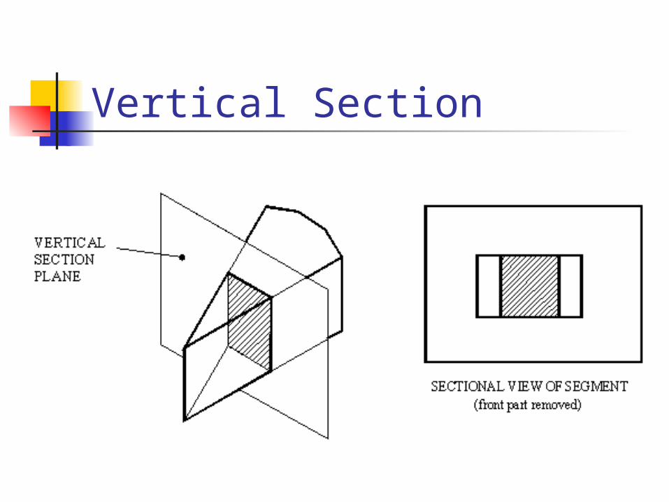
Vertical Section

Horizontal Section

Cutting Plane

Sections (Webs)

Half Section

Part Section

Revolved Section

Exceptions
• Sectioning is a process which should be used only to simplify or clarify a drawing.
•There are some engineering details that, if sectioned, lose their identity or would create a wrong impression. These items are never sectioned.

Exceptions

Exceptions

Exceptions
Engineering details that do not show hatching when sectioned• Nuts & Bolts
• Studs
• Screws
• Shafts
• Webs
• Ball Bearings & Ball Races
• Roller Bearings & Roller Races
• Keys
• Pins
• Gear Teeth

Hatching
Hatching is used in British Standards therefore it is also used throughout the Higher course.
• Hatching is drawn using type B lines.
• Equally spaced at 45 degrees
• Preferably not less than 4 mm apart
• However if hatching a small area spacing should be reduced but never less than 1mm
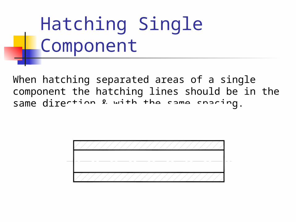
Hatching Single Component
When hatching separated areas of a single component the hatching lines should be in the same direction & with the same spacing.

Hatching Adjacent PartsWhere different sectioned parts meet on an assembly drawing, the direction of hatching should normally be reversed & staggered.

Hatching Adjacent PartsIn cases where hatching on adjacent parts must be at the same angle the lines should be staggered & may be more closely spaced.

Hatching Large Areas
Hatching of large areas may be limited to that part of the area which touches adjacent parts, or the outline of the large part.

Hatching Thin Material
Thin Material in section may be filled in, in preference to showing the material thickness out of scale & hatched. When adjacent parts are thus shown a clear space of not less than 1mm should be left between them.

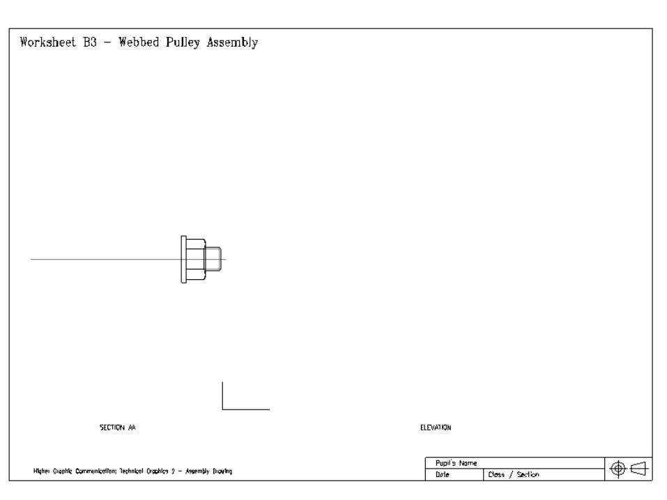
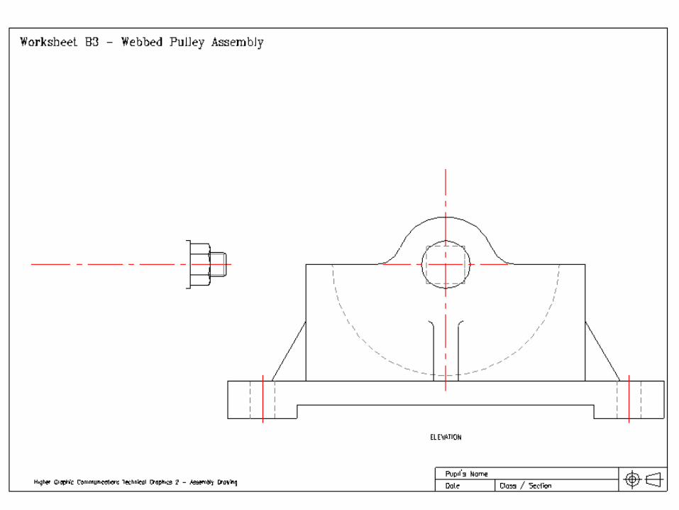
B3 - Webbed Pulley AssemblyDimensioned orthographic views of the components and an exploded isometric view of a Webbed
Pulley arrangement are shown drawn to scale.On the worksheet provided, draw, full size;a) The elevation fully assembled. Show hidden detail.b) The section on A-A of the assembly.
Higher Graphic Communication: Technical Graphics 2 - Assembly DrawingØ
106
180
160
260
220
8 3863
130
15
22S
Q
Ø30
4 HOLES Ø14
90
78
48
8Ø
14
25
22SQ
Ø20
3590 14
Ø30
Ø88
46
Ø72
Ø46
20 (4 OFF)
R28
R65
14
22
R20
Ø20
Ø30
46
24 88
1512

Questions For B3 (TG2)
a. The elevation of the full assembly, showing all hidden detail.
b. The SECTION A-A, omitting hidden detail.
Dimensioned orthographic views together with an exploded isometric view of a webbed pulley as shown. On Worksheet B3 draw full size, using the given dimensions.