grass trimmer/brush cutter - echo usa trimmer/brush cutter operator's manual model srm - 230...
TRANSCRIPT
Grass Trimmer/Brush CutterOperator's Manual
MODEL SRM - 230Serial Number 05001001 - 05143223
SRM - 230SSerial Number 05001001 - 05014429
WARNING DANGERRead rules for safe operation and instructions carefully. ECHO provides an Operator'sManual and a Safety Manual. Both must be read and understood for proper and safeoperation.
X7502099201X75000369111/03
2
INTRODUCTION
Welcome to the ECHO family. This ECHO product was designed and manufactured to provide long life and on-the-jobdependability. Read and understand this manual and the SAFETY MANUAL you found in the same package. You willfind both easy to use and full of helpful operating tips and SAFETY messages.
THE OPERATOR'S MANUALRead and understand this manual before operation. Keep it in a safeplace for future reference. It contains specifications and information foroperation, starting, stopping, maintenance, storage and assemblyspecific to this product.
THE SAFETY MANUALRead and understand this manual before operation. Keep it in a safeplace for future reference. It explains possible hazards involved with theuse of Grass Trimmers and Brush Cutters and what measures youshould take to make their use safer.
TABLE OF CONTENTS
Introduction ........................................................................ 2- The Operator's Manual .............................................. 2- The Safety manual ...................................................... 2
Manual Safety Symbols and Important Information ......... 3Safety .................................................................................. 3
- Decals ......................................................................... 3- International Symbols ................................................. 4
Safety Instructions ............................................................. 5- Personal Condition and Safety Equipment ................. 5- Extended Operation/Extreme Conditions ................... 5- Equipment .................................................................. 6- Safe Operation ............................................................ 7
Emission Control ................................................................ 7Description ......................................................................... 8
- Contents ..................................................................... 8Specifications .................................................................... 10Assembly .......................................................................... 11
- Plastic Shield Installation .......................................... 11- Nylon Line Head Installation ................................... 11- Front Handle Installation .......................................... 12
Pre-Operation ................................................................... 12- Operation with Blades .............................................. 12- Fuel ........................................................................... 15
Operation .......................................................................... 16- Starting Cold Engine ................................................. 16- Starting Warm Engine ............................................... 17- Stopping Engine ........................................................ 17
Maintenance ..................................................................... 18- Skill Levels ................................................................ 18- Maintenance Intervals .............................................. 18- Air Filter ................................................................... 19- Fuel Filter ................................................................. 19- Spark Plug ................................................................. 20- Cooling System Cleaning .......................................... 20- Exhaust System ........................................................ 21- Carburetor Adjustment Emission ............................. 22- Lubrication ................................................................ 23- Nylon Line Replacement .......................................... 24- Sharpening Metal Blades .......................................... 25
Troubleshooting ................................................................ 26Storage .............................................................................. 27Servicing Information ........................................................ 28
- Parts .......................................................................... 28- Service ....................................................................... 28- ECHO Consumer Product Support .......................... 28- Warranty Card .......................................................... 28- Additional or Replacement Manuals ........................ 28
Specifications, descriptions and illustrative material inthis literature are as accurate as known at the time ofpublication, but are subject to change without notice.Illustrations may include optional equipment andaccessories, and may not include all standard equipment.
Copyright© 2003 By Echo, IncorporatedAll Rights Reserved.
GRASS TRIMMER/BRUSH CUTTEROPERATOR'S MANUAL 3
IMPORTANT The enclosed messageprovides information necessary for theprotection of the unit.
NOTE This enclosed message providestips for use, care and maintenance of theunit.
This symbol accompanied by the words WARNINGand DANGER calls attention to an act or conditionthat can lead to serious personal injury to operatorand bystanders.
The circle with the slash symbol means whatever isshown within the circle is prohibited.
MANUAL SAFETY SYMBOLS AND IMPORTANT INFORMATION
Throughout this manual and on the product itself, you will find safetyalerts and helpful, informational messages preceded by symbols or keywords. The following is an explanation of those symbols and key wordsand what they mean to you.
SAFETY
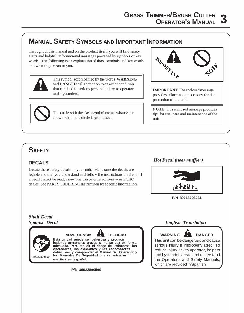
DECALSLocate these safety decals on your unit. Make sure the decals arelegible and that you understand and follow the instructions on them. Ifa decal cannot be read, a new one can be ordered from your ECHOdealer. See PARTS ORDERING instructions for specific information.
89022890560
Shaft DecalSpanish Decal English Translation
ADVERTENCIA PELIGROEsta unidad puede ser peligrosa y producirlesiones personales graves si no se usa en formaadecuada. Para reducir el riesgo de lesionarse, losoperadores, los ayudantes y los espectadoresdeben leer y comprender el Manual Del Operador ylos Manuales De Seguridad que se entreganescritos en español.
WARNING DANGERThis unit can be dangerous and causeserious injury if improperly used. Toreduce injury risk to operator, helpersand bystanders, read and understandthe Operator's and Safety Manuals,which are provided in Spanish.
Hot Decal (near muffler)
P/N 89016006361
P/N 89022890560
4
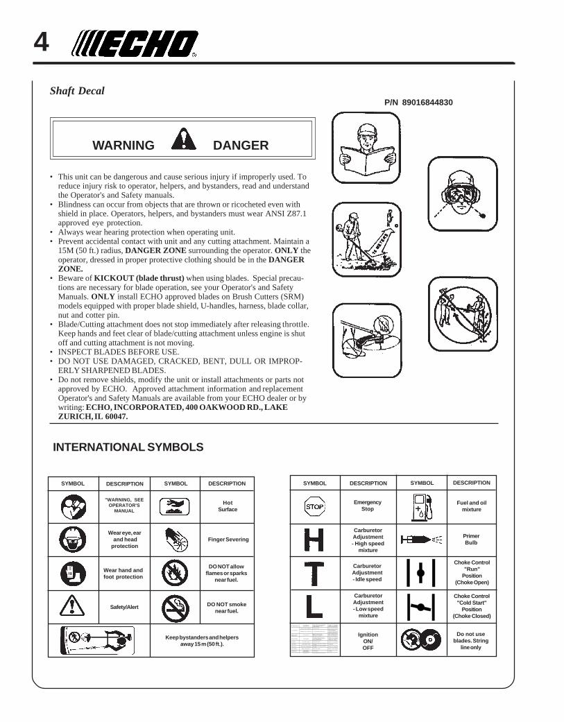
Shaft Decal
WARNING DANGER
• This unit can be dangerous and cause serious injury if improperly used. Toreduce injury risk to operator, helpers, and bystanders, read and understandthe Operator's and Safety manuals.
• Blindness can occur from objects that are thrown or ricocheted even withshield in place. Operators, helpers, and bystanders must wear ANSI Z87.1approved eye protection.
• Always wear hearing protection when operating unit.• Prevent accidental contact with unit and any cutting attachment. Maintain a
15M (50 ft.) radius, DANGER ZONE surrounding the operator. ONLY theoperator, dressed in proper protective clothing should be in the DANGERZONE.
• Beware of KICKOUT (blade thrust) when using blades. Special precau-tions are necessary for blade operation, see your Operator's and SafetyManuals. ONLY install ECHO approved blades on Brush Cutters (SRM)models equipped with proper blade shield, U-handles, harness, blade collar,nut and cotter pin.
• Blade/Cutting attachment does not stop immediately after releasing throttle.Keep hands and feet clear of blade/cutting attachment unless engine is shutoff and cutting attachment is not moving.
• INSPECT BLADES BEFORE USE.• DO NOT USE DAMAGED, CRACKED, BENT, DULL OR IMPROP-
ERLY SHARPENED BLADES.• Do not remove shields, modify the unit or install attachments or parts not
approved by ECHO. Approved attachment information and replacementOperator's and Safety Manuals are available from your ECHO dealer or bywriting: ECHO, INCORPORATED, 400 OAKWOOD RD., LAKEZURICH, IL 60047.
P/N 89016844830
INTERNATIONAL SYMBOLS
roterubracta taleufoNroterubrac
deggolcreniartsleuFdeggolcenilleuF
roterubraC
ecalperronaelCecalperronaelCdohcEruoyeeS
rednilycta
rednilyctaleufoN roterubraC dohcEruoyeeS
leufhtiwtewrelffuM hcirooterutxiMleuF
ekohcnepOiaecalper/naelC
oterubractsujdAdohcEruoyeeS
dnetakraeriwgulp krapsoN
ffohctiwspotSmelborplacirtcelE
hctiwskcolretnI
OothctiwsnruTdohcEruoyeeSdohcEruoyeeS
gulptakra krapsoN
tcerrocnipagkrapSnobrachtiwderevoC
leufhtiwdeluoFevitcefedgulP
mm56.ottsujdAecalperronaelCecalperronaelC
gulpecalpeR
retlifriA ytridretlifriA raewlamroN ecalperronaelC
retlifleu ytridretlifleuF seudiser/stnanimatnoCleufni ecalpeR
tnevleu deggulptnevleuF seudiser/stnanimatnoCleufni ecalperronaelC
gulPkrap nrow/ytridgulP raewlamroN sujdadnanaelC
roterubra reporpmItnemtsujda noitarbiV tsujdA
metsySgni evissecxE ninoitarepodednetxE naelC
HotSurface
CarburetorAdjustment- Idle speed
CarburetorAdjustment- High speed
mixture
DESCRIPTION SYMBOLSYMBOL
"WARNING, SEEOPERATOR'S
MANUAL
Wear eye, ear and headprotection
EmergencyStop
Fuel and oilmixture
Finger Severing
CarburetorAdjustment- Low speed
mixture
PrimerBulb
IgnitionON/OFF
Wear hand andfoot protection
Safety/Alert
Keep bystanders and helpersaway 15 m (50 ft.).
DO NOT smokenear fuel.
DO NOT allowflames or sparks
near fuel.
DESCRIPTION SYMBOL DESCRIPTION SYMBOL DESCRIPTION
Choke Control"Cold Start"
Position(Choke Closed)
Choke Control"Run"
Position(Choke Open)
Do not useblades. String
line only
GRASS TRIMMER/BRUSH CUTTEROPERATOR'S MANUAL 5
Physical Condition --Your judgment and physical dexterity may not be good:
• if you are tired or sick,• if you are taking medication,• if you have taken alcohol or drugs.
Operate unit only if you are physically and mentally well.
Eye Protection --Wear eye protection that meets ANSI Z87.1 or CErequirements whenever you operate the trimmer.
Hand Protection --Wear no-slip, heavy duty work gloves to improve yourgrip on the Trimmer/Brush Cutter handles. Gloves alsoreduce the transmission of machine vibration to yourhands.
Hearing Protection --ECHO recommends wearing hearing protection wheneverunit is used.
Proper Clothing --Wear snug fitting, durable clothing;• Pants should have long legs, shirts with long sleeves.• DO NOT WEAR SHORTS,• DO NOT WEAR TIES, SCARVES, JEWELRY.
Wear sturdy work shoes with non-skid soles;• DO NOT WEAR OPEN TOED SHOES,• DO NOT OPERATE UNIT BAREFOOTED.
SAFETY INSTRUCTIONSPERSONAL CONDITION AND SAFETY EQUIPMENT
WARNING DANGERTrimmer/Brush Cutter users risk injury to themselves and others if the trimmer/brush cutter is used improperlyor safety precautions are not followed. Proper clothing and safety gear must be worn when operating atrimmer/brush cutter.
EXTENDED OPERATION/EXTREME CONDITIONS
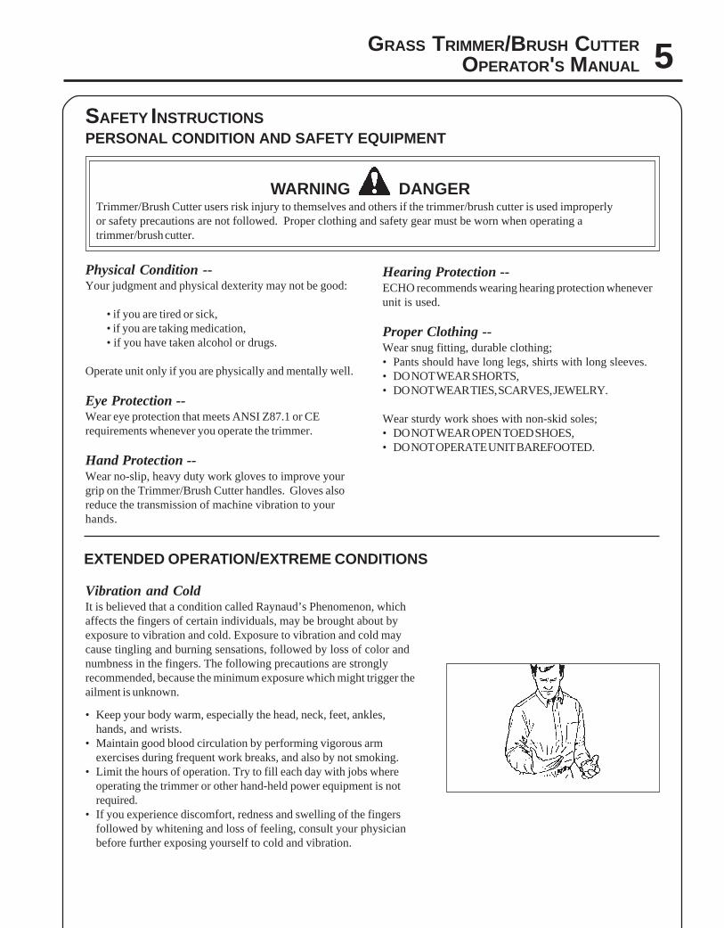
Vibration and ColdIt is believed that a condition called Raynaud’s Phenomenon, whichaffects the fingers of certain individuals, may be brought about byexposure to vibration and cold. Exposure to vibration and cold maycause tingling and burning sensations, followed by loss of color andnumbness in the fingers. The following precautions are stronglyrecommended, because the minimum exposure which might trigger theailment is unknown.
• Keep your body warm, especially the head, neck, feet, ankles,hands, and wrists.
• Maintain good blood circulation by performing vigorous armexercises during frequent work breaks, and also by not smoking.
• Limit the hours of operation. Try to fill each day with jobs whereoperating the trimmer or other hand-held power equipment is notrequired.
• If you experience discomfort, redness and swelling of the fingersfollowed by whitening and loss of feeling, consult your physicianbefore further exposing yourself to cold and vibration.
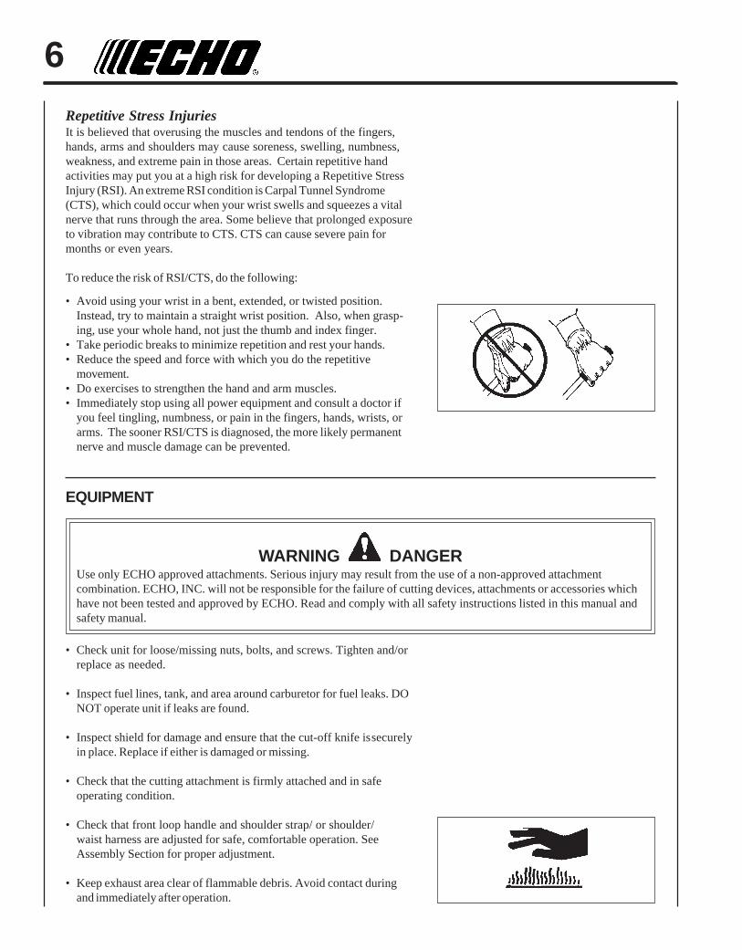
6Repetitive Stress InjuriesIt is believed that overusing the muscles and tendons of the fingers,hands, arms and shoulders may cause soreness, swelling, numbness,weakness, and extreme pain in those areas. Certain repetitive handactivities may put you at a high risk for developing a Repetitive StressInjury (RSI). An extreme RSI condition is Carpal Tunnel Syndrome(CTS), which could occur when your wrist swells and squeezes a vitalnerve that runs through the area. Some believe that prolonged exposureto vibration may contribute to CTS. CTS can cause severe pain formonths or even years.
To reduce the risk of RSI/CTS, do the following:
• Avoid using your wrist in a bent, extended, or twisted position.Instead, try to maintain a straight wrist position. Also, when grasp-ing, use your whole hand, not just the thumb and index finger.
• Take periodic breaks to minimize repetition and rest your hands.• Reduce the speed and force with which you do the repetitive
movement.• Do exercises to strengthen the hand and arm muscles.• Immediately stop using all power equipment and consult a doctor if
you feel tingling, numbness, or pain in the fingers, hands, wrists, orarms. The sooner RSI/CTS is diagnosed, the more likely permanentnerve and muscle damage can be prevented.
EQUIPMENT
WARNING DANGERUse only ECHO approved attachments. Serious injury may result from the use of a non-approved attachmentcombination. ECHO, INC. will not be responsible for the failure of cutting devices, attachments or accessories whichhave not been tested and approved by ECHO. Read and comply with all safety instructions listed in this manual andsafety manual.
• Check unit for loose/missing nuts, bolts, and screws. Tighten and/orreplace as needed.
• Inspect fuel lines, tank, and area around carburetor for fuel leaks. DONOT operate unit if leaks are found.
• Inspect shield for damage and ensure that the cut-off knife issecurelyin place. Replace if either is damaged or missing.
• Check that the cutting attachment is firmly attached and in safeoperating condition.
• Check that front loop handle and shoulder strap/ or shoulder/waist harness are adjusted for safe, comfortable operation. SeeAssembly Section for proper adjustment.
• Keep exhaust area clear of flammable debris. Avoid contact duringand immediately after operation.
GRASS TRIMMER/BRUSH CUTTEROPERATOR'S MANUAL 7
SAFE OPERATION
WARNING DANGERDo not operate this product indoors or in inadequately ventilatedareas. Engine exhaust contains poisonous emissions and can causeserious injury or death.
Read the Manuals• Provide all users of this equipment with the Operator's Manual and
Safety Manual for instructions on Safe Operation.
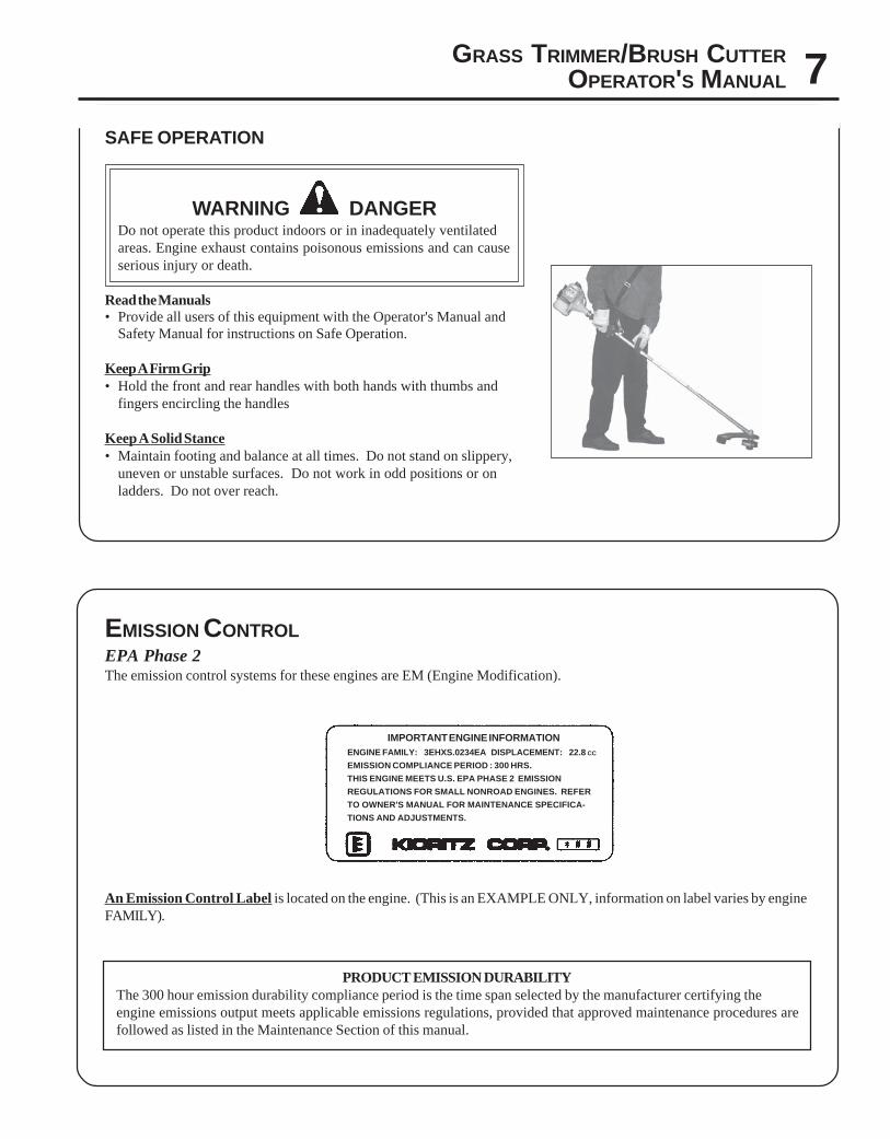
Keep A Firm Grip• Hold the front and rear handles with both hands with thumbs and
fingers encircling the handles
Keep A Solid Stance• Maintain footing and balance at all times. Do not stand on slippery,
uneven or unstable surfaces. Do not work in odd positions or onladders. Do not over reach.
EMISSION CONTROLEPA Phase 2The emission control systems for these engines are EM (Engine Modification).
An Emission Control Label is located on the engine. (This is an EXAMPLE ONLY, information on label varies by engineFAMILY).
PRODUCT EMISSION DURABILITYThe 300 hour emission durability compliance period is the time span selected by the manufacturer certifying theengine emissions output meets applicable emissions regulations, provided that approved maintenance procedures arefollowed as listed in the Maintenance Section of this manual.
IMPORTANT ENGINE INFORMATIONENGINE FAMILY: 3EHXS.0234EA DISPLACEMENT: 22.8 CC
EMISSION COMPLIANCE PERIOD : 300 HRS.
THIS ENGINE MEETS U.S. EPA PHASE 2 EMISSION
REGULATIONS FOR SMALL NONROAD ENGINES. REFER
TO OWNER'S MANUAL FOR MAINTENANCE SPECIFICA-
TIONS AND ADJUSTMENTS.
8
1
234
56
7
8
9 10
SafetyVideo
20
11
13
14
15
16
17
18
12
19
DESCRIPTION
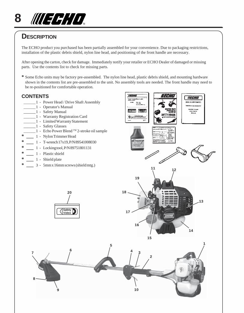
The ECHO product you purchased has been partially assembled for your convenience. Due to packaging restrictions,installation of the plastic debris shield, nylon line head, and positioning of the front handle are necessary.
After opening the carton, check for damage. Immediately notify your retailer or ECHO Dealer of damaged or missingparts. Use the contents list to check for missing parts.
* Some Echo units may be factory pre-assembled. The nylon line head, plastic debris shield, and mounting hardwareshown in the contents list are pre-assembled to the unit. No assembly tools are needed. The front handle may need tobe re-positioned for comfortable operation.
CONTENTS______1 - Power Head / Drive Shaft Assembly______1 - Operator's Manual______1 - Safety Manual______1 - Warranty Registration Card______1 - Limited Warranty Statement______1 - Safety Glasses______1 - Echo Power Blend TM 2-stroke oil sample
* ___ 1 - Nylon Trimmer Head
* ___ 1 - T-wrench 17x19, P/N 89541008030
* ___ 1 - Locking tool, P/N 89751801131
* ___ 1 - Plastic shield
* ___ 1 - Shield plate
* ___ 3 - 5mm x 16mm screws (shield mtg.)
GRASS TRIMMER/BRUSH CUTTEROPERATOR'S MANUAL 9
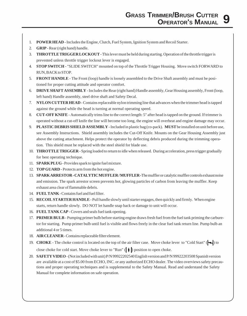
1. POWER HEAD - Includes the Engine, Clutch, Fuel System, Ignition System and Recoil Starter.
2. GRIP - Rear (right hand) handle.
3. THROTTLE TRIGGER LOCKOUT - This lever must be held during starting. Operation of the throttle trigger is
prevented unless throttle trigger lockout lever is engaged.
4. STOP SWITCH - "SLIDE SWITCH" mounted on top of the Throttle Trigger Housing. Move switch FORWARD to
RUN, BACK to STOP.
5. FRONT HANDLE - The Front (loop) handle is loosely assembled to the Drive Shaft assembly and must be posi-
tioned for proper cutting attitude and operator comfort.
6. DRIVE SHAFT ASSEMBLY - Includes the Rear (right hand) Handle assembly, Gear Housing assembly, Front (loop,
left hand) Handle assembly, steel drive shaft and Safety Decal.
7. NYLON CUTTER HEAD - Contains replaceable nylon trimming line that advances when the trimmer head is tapped
against the ground while the head is turning at normal operating speed.
8. CUT-OFF KNIFE - Automatically trims line to the correct length: 5" after head is tapped on the ground. If trimmer is
operated without a cut-off knife the line will become too long, the engine will overheat and engine damage may occur.
9. PLASTIC DEBRIS SHIELD ASSEMBLY - Included in plastic bag (co-pack). MUST be installed on unit before use,
see Assembly Instructions. Shield assembly includes the Cut-Off Knife. Mounts on the Gear Housing Assembly just
above the cutting attachment. Helps protect the operator by deflecting debris produced during the trimming opera-
tion. This shield must be replaced with the steel shield for blade use.
10. THROTTLE TRIGGER - Spring loaded to return to idle when released. During acceleration, press trigger gradually
for best operating technique.
11. SPARK PLUG - Provides spark to ignite fuel mixture.
12. TOP GUARD - Protects arm from the hot engine.
13. SPARK ARRESTOR - CATALYTIC MUFFLER / MUFFLER -The muffler or catalytic muffler controls exhaust noise
and emission. The spark arrestor screen prevents hot, glowing particles of carbon from leaving the muffler. Keep
exhaust area clear of flammable debris.
14. FUEL TANK - Contains fuel and fuel filter.
15. RECOIL STARTER HANDLE - Pull handle slowly until starter engages, then quickly and firmly. When engine
starts, return handle slowly. DO NOT let handle snap back or damage to unit will occur.
16. FUEL TANK CAP - Covers and seals fuel tank opening.
17. PRIMER BULB - Pumping primer bulb before starting engine draws fresh fuel from the fuel tank priming the carbure-
tor for starting. Pump primer bulb until fuel is visible and flows freely in the clear fuel tank return line. Pump bulb an
additional 4 or 5 times.
18. AIR CLEANER - Contains replaceable filter element.
19. CHOKE - The choke control is located on the top of the air filter case. Move choke lever to "Cold Start" ( ) to
close choke for cold start. Move choke lever to "Run" ( ) position to open choke.
20. SAFETY VIDEO - (Not included with unit) P/N 99922202540 English version and P/N 99922203508 Spanish versionare available at a cost of $5.00 from ECHO, INC. or any authorized ECHO dealer. The video overviews safety precau-tions and proper operating techniques and is supplemental to the Safety Manual. Read and understand the Safety
Manual for complete information on safe operation.
10
SPECIFICATIONS
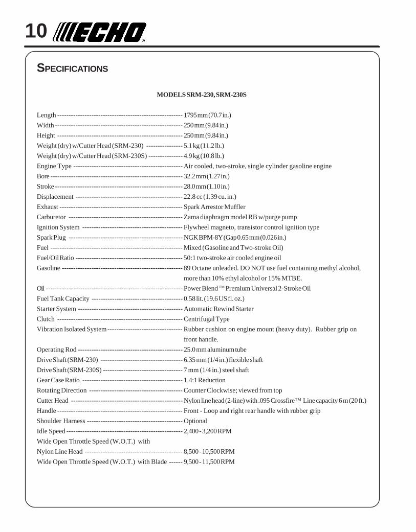
MODELS SRM-230, SRM-230S
Length ------------------------------------------------------- 1795 mm (70.7 in.)
Width -------------------------------------------------------- 250 mm (9.84 in.)
Height ------------------------------------------------------- 250 mm (9.84 in.)
Weight (dry) w/Cutter Head (SRM-230) ---------------- 5.1 kg (11.2 lb.)
Weight (dry) w/Cutter Head (SRM-230S) --------------- 4.9 kg (10.8 lb.)
Engine Type ------------------------------------------------ Air cooled, two-stroke, single cylinder gasoline engine
Bore ---------------------------------------------------------- 32.2 mm (1.27 in.)
Stroke -------------------------------------------------------- 28.0 mm (1.10 in.)
Displacement ----------------------------------------------- 22.8 cc (1.39 cu. in.)
Exhaust ------------------------------------------------------ Spark Arrestor Muffler
Carburetor -------------------------------------------------- Zama diaphragm model RB w/purge pump
Ignition System -------------------------------------------- Flywheel magneto, transistor control ignition type
Spark Plug -------------------------------------------------- NGK BPM-8Y (Gap 0.65 mm (0.026 in.)
Fuel ---------------------------------------------------------- Mixed (Gasoline and Two-stroke Oil)
Fuel/Oil Ratio ----------------------------------------------- 50:1 two-stroke air cooled engine oil
Gasoline ----------------------------------------------------- 89 Octane unleaded. DO NOT use fuel containing methyl alcohol,
more than 10% ethyl alcohol or 15% MTBE.
Oil ------------------------------------------------------------ Power Blend TM Premium Universal 2-Stroke Oil
Fuel Tank Capacity ---------------------------------------- 0.58 lit. (19.6 US fl. oz.)
Starter System ---------------------------------------------- Automatic Rewind Starter
Clutch ------------------------------------------------------- Centrifugal Type
Vibration Isolated System--------------------------------- Rubber cushion on engine mount (heavy duty). Rubber grip on
front handle.
Operating Rod ---------------------------------------------- 25.0 mm aluminum tube
Drive Shaft (SRM-230) ------------------------------------ 6.35 mm (1/4 in.) flexible shaft
Drive Shaft (SRM-230S) ----------------------------------- 7 mm (1/4 in.) steel shaft
Gear Case Ratio -------------------------------------------- 1.4:1 Reduction
Rotating Direction ----------------------------------------- Counter Clockwise; viewed from top
Cutter Head ------------------------------------------------- Nylon line head (2-line) with .095 Crossfire™ Line capacity 6 m (20 ft.)
Handle ------------------------------------------------------- Front - Loop and right rear handle with rubber grip
Shoulder Harness ------------------------------------------ Optional
Idle Speed --------------------------------------------------- 2,400 - 3,200 RPM
Wide Open Throttle Speed (W.O.T.) with
Nylon Line Head ------------------------------------------- 8,500 - 10,500 RPM
Wide Open Throttle Speed (W.O.T.) with Blade ------ 9,500 - 11,500 RPM
GRASS TRIMMER/BRUSH CUTTEROPERATOR'S MANUAL 11
ASSEMBLY
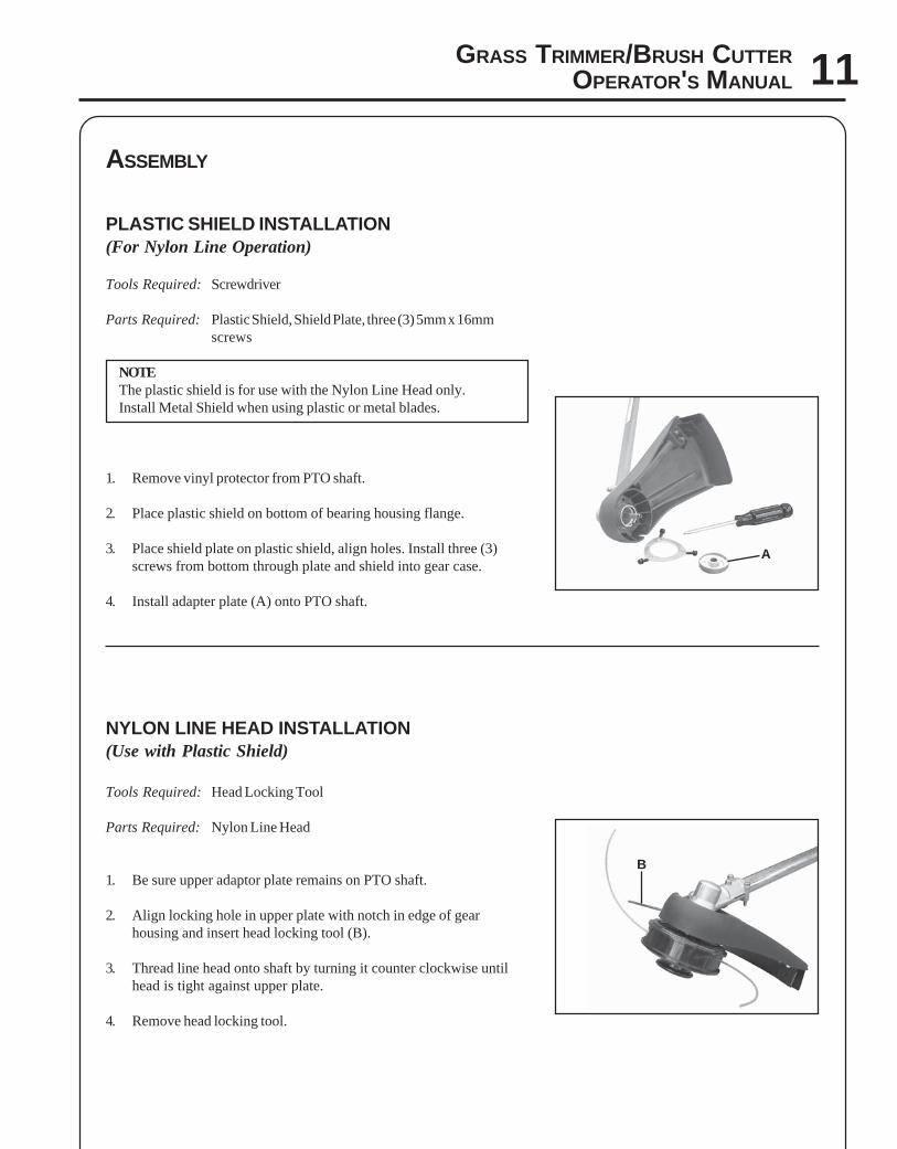
PLASTIC SHIELD INSTALLATION(For Nylon Line Operation)
Tools Required: Screwdriver
Parts Required: Plastic Shield, Shield Plate, three (3) 5mm x 16mmscrews
NOTEThe plastic shield is for use with the Nylon Line Head only.Install Metal Shield when using plastic or metal blades.
1. Remove vinyl protector from PTO shaft.
2. Place plastic shield on bottom of bearing housing flange.
3. Place shield plate on plastic shield, align holes. Install three (3)screws from bottom through plate and shield into gear case.
4. Install adapter plate (A) onto PTO shaft.
NYLON LINE HEAD INSTALLATION(Use with Plastic Shield)
Tools Required: Head Locking Tool
Parts Required: Nylon Line Head
1. Be sure upper adaptor plate remains on PTO shaft.
2. Align locking hole in upper plate with notch in edge of gearhousing and insert head locking tool (B).
3. Thread line head onto shaft by turning it counter clockwise untilhead is tight against upper plate.
4. Remove head locking tool.
A
B

12
PRE - OPERATION
OPERATION WITH BLADES
Preparing the Trimmer/Brush Cutter for Blade Use
WARNING DANGERBlade use DEMANDS specific Brush Cutter configuration. Operation without specified shield, handle, and harnesscan result in serious personal injury. Follow installation instructions included in optional kits.
FRONT HANDLE INSTALLATION
Tools Required: Screwdriver
Parts Required: Front Handle Assembly
1. Position front handle for comfortable operation and secure screws.
A
C
B
Grass/Weed Blades Require:
Install Blade Conversion Kit, P/N 99944200415 -Includes metal shield (A), barrier bar (B), andshoulder harness (C).
NOTEThe Barrier Bar is NOT A HANDLE and shouldnot be gripped when using or carrying the unit.
NOTEThe Barrier Bar is used to restrict rearward movement of the unit. For heavy-duty or extended use, U-handles shouldbe used. See your Echo dealer or Trimmer/Brush Cutter Safety Manual for details regarding U-Handles. If you haveadditional questions, contact your Echo Service Dealer, or call Echo directly at 1-800-673-1558.
GRASS TRIMMER/BRUSH CUTTEROPERATOR'S MANUAL 13
CA
D
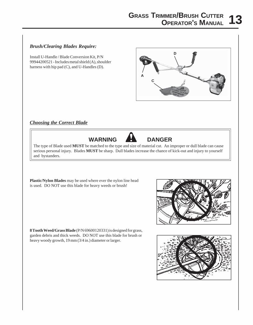
Choosing the Correct Blade
WARNING DANGERThe type of Blade used MUST be matched to the type and size of material cut. An improper or dull blade can causeserious personal injury. Blades MUST be sharp. Dull blades increase the chance of kick-out and injury to yourselfand bystanders.
Plastic/Nylon Blades may be used where ever the nylon line headis used. DO NOT use this blade for heavy weeds or brush!
8 Tooth Weed/Grass Blade (P/N 69600120331) is designed for grass,garden debris and thick weeds. DO NOT use this blade for brush orheavy woody growth, 19 mm (3/4 in.) diameter or larger.
Brush/Clearing Blades Require:
Install U-Handle / Blade Conversion Kit, P/N99944200521 - Includes metal shield (A), shoulderharness with hip pad (C), and U-Handles (D).
14
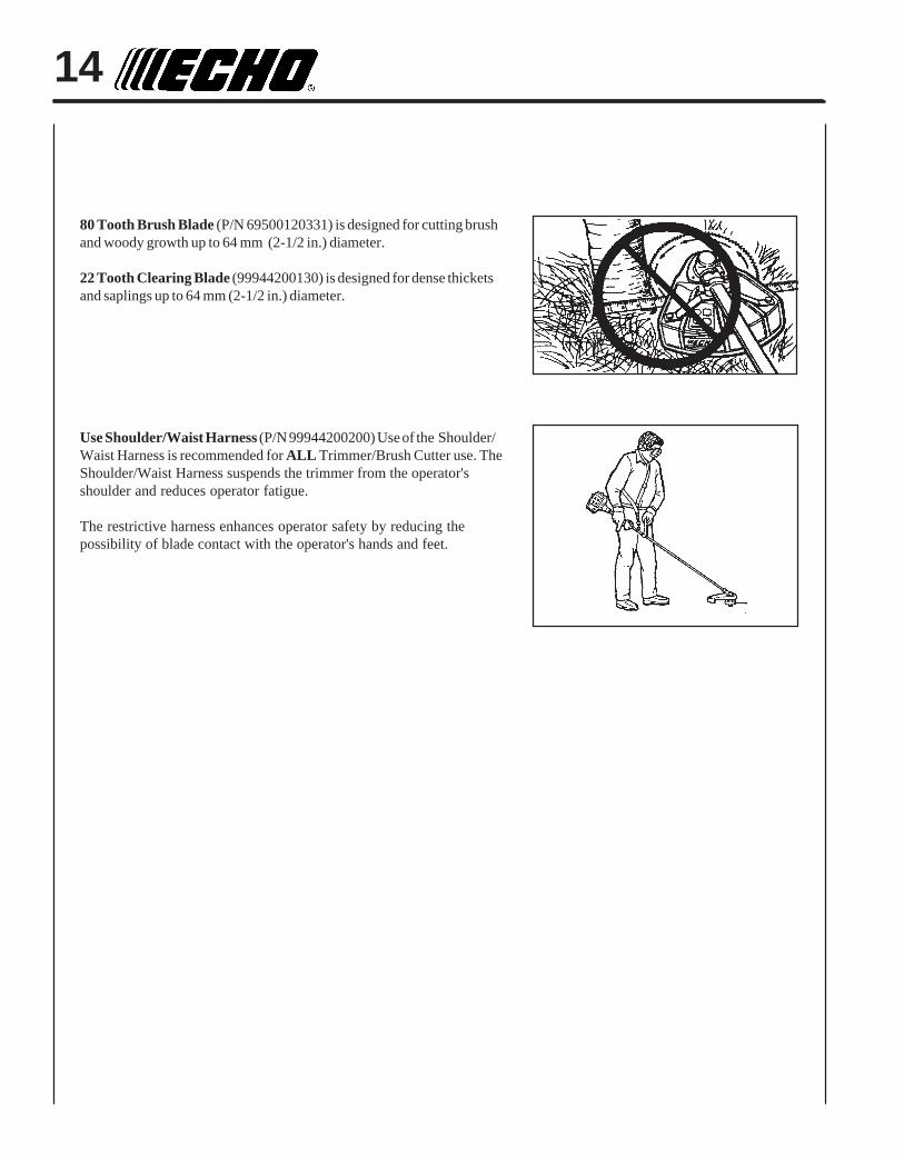
80 Tooth Brush Blade (P/N 69500120331) is designed for cutting brushand woody growth up to 64 mm (2-1/2 in.) diameter.
22 Tooth Clearing Blade (99944200130) is designed for dense thicketsand saplings up to 64 mm (2-1/2 in.) diameter.
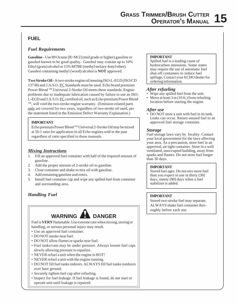
Use Shoulder/Waist Harness (P/N 99944200200) Use of the Shoulder/Waist Harness is recommended for ALL Trimmer/Brush Cutter use. TheShoulder/Waist Harness suspends the trimmer from the operator'sshoulder and reduces operator fatigue.
The restrictive harness enhances operator safety by reducing thepossibility of blade contact with the operator's hands and feet.
GRASS TRIMMER/BRUSH CUTTEROPERATOR'S MANUAL 15
FUEL
Fuel Requirements
Gasoline - Use 89 Octane [R+M/2] (mid grade or higher) gasoline orgasohol known to be good quality. Gasohol may contain up to 10%Ethyl (grain) alcohol or 15% MTBE (methyl tertiary-butyl ether).Gasohol containing methyl (wood) alcohol is NOT approved.
Two Stroke Oil - A two-stroke engine oil meeting ISO-L-EGD (ISO/CD13738) and J.A.S.O. FC Standards must be used. Echo brand premiumPower Blend TM Universal 2-Stroke Oil meets these standards. Engineproblems due to inadequate lubrication caused by failure to use an ISO-L-EGD and J.A.S.O. FC certified oil, such as Echo premium Power BlendTM, will void the two-stroke engine warranty. (Emission related partsonly are covered for two years, regardless of two-stroke oil used, perthe statement listed in the Emission Defect Warranty Explanation.)
IMPORTANTEcho premium Power Blend TM Universal 2-Stroke Oil may be mixedat 50:1 ratio for application in all Echo engines sold in the pastregardless of ratio specified in those manuals.
Mixing Instructions1. Fill an approved fuel container with half of the required amount of
gasoline.2. Add the proper amount of 2-stroke oil to gasoline.3. Close container and shake to mix oil with gasoline.4. Add remaining gasoline and remix.5. Install fuel container cap and wipe any spilled fuel from container
and surrounding area.
Handling Fuel
WARNING DANGERFuel is VERY flammable. Use extreme care when mixing, storing orhandling, or serious personal injury may result.• Use an approved fuel container.• DO NOT smoke near fuel.• DO NOT allow flames or sparks near fuel.• Fuel tanks/cans may be under pressure. Always loosen fuel caps
slowly allowing pressure to equalize.• NEVER refuel a unit when the engine is HOT!• NEVER refuel a unit with the engine running.• DO NOT fill fuel tanks indoors. ALWAYS fill fuel tanks outdoors
over bare ground.• Securely tighten fuel cap after refueling.• Inspect for fuel leakage. If fuel leakage is found, do not start or
operate unit until leakage is repaired.
IMPORTANTSpilled fuel is a leading cause ofhydrocarbon emissions. Some statesmay require the use of automatic fuelshut-off containers to reduce fuelspillage. Contact your ECHO dealer forordering information.
After refueling• Wipe any spilled fuel from the unit.• Move at least 3 m (10 ft.) from refueling
location before starting the engine.
After use• DO NOT store a unit with fuel in its tank.
Leaks can occur. Return unused fuel to anapproved fuel storage container.
StorageFuel storage laws vary by locality. Contactyour local government for the laws affectingyour area. As a precaution, store fuel in anapproved, air tight container. Store in a wellventilated, unoccupied building, away fromsparks and flames. Do not store fuel longerthan 30 days.
IMPORTANTStored fuel ages. Do not mix more fuelthan you expect to use in thirty (30)days, ninety (90) days when a fuelstabilizer is added.
IMPORTANTStored two-stroke fuel may separate.ALWAYS shake fuel container thor-oughly before each use.
16
OPERATION
STARTING COLD ENGINE
WARNING DANGERThe attachment will operate immediately when the engine starts andcould result in loss of control and possible serious injury. Keepmovable parts of the attachment off the ground and away fromobjects that could become entangled or thrown.
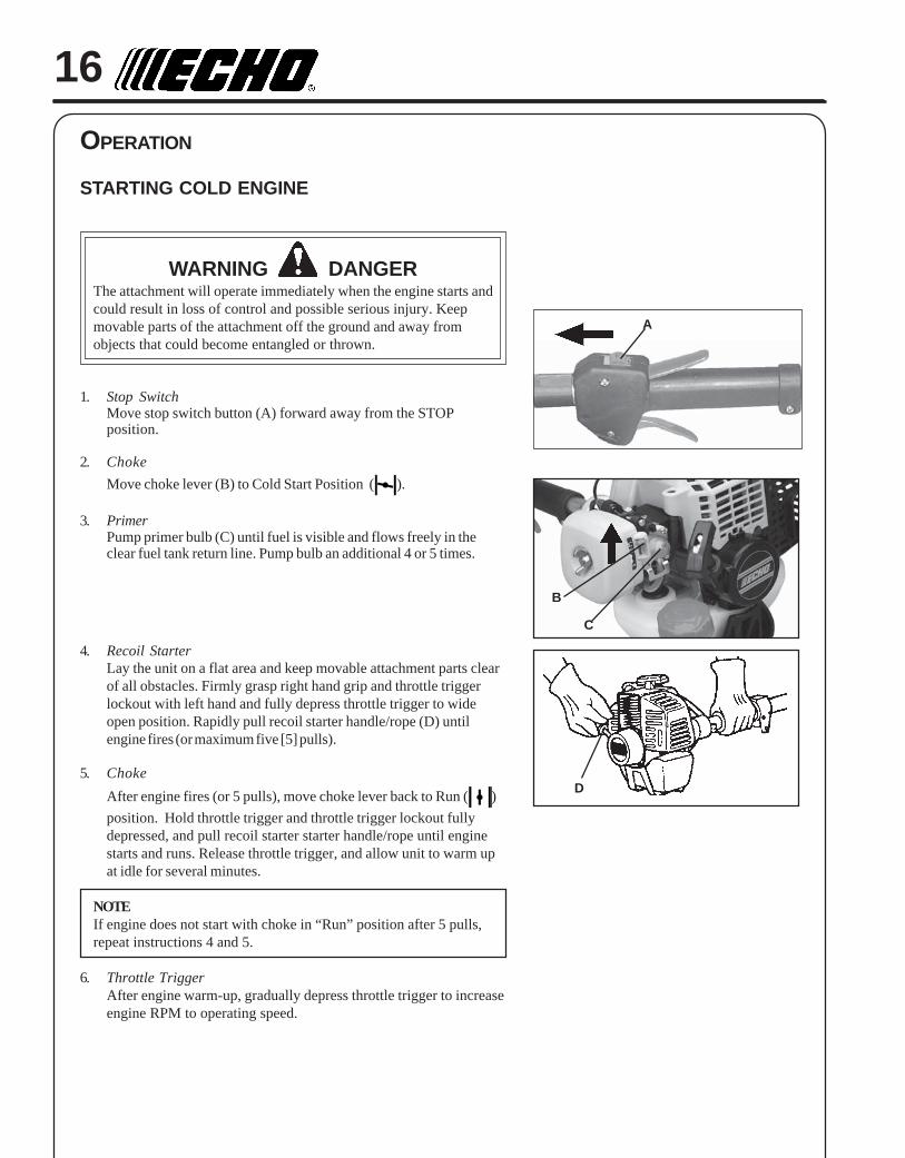
1. Stop SwitchMove stop switch button (A) forward away from the STOPposition.
2. Choke
Move choke lever (B) to Cold Start Position ( ).
3. PrimerPump primer bulb (C) until fuel is visible and flows freely in theclear fuel tank return line. Pump bulb an additional 4 or 5 times.
4. Recoil StarterLay the unit on a flat area and keep movable attachment parts clearof all obstacles. Firmly grasp right hand grip and throttle triggerlockout with left hand and fully depress throttle trigger to wideopen position. Rapidly pull recoil starter handle/rope (D) untilengine fires (or maximum five [5] pulls).
5. Choke
After engine fires (or 5 pulls), move choke lever back to Run ( )
position. Hold throttle trigger and throttle trigger lockout fullydepressed, and pull recoil starter starter handle/rope until enginestarts and runs. Release throttle trigger, and allow unit to warm upat idle for several minutes.
NOTEIf engine does not start with choke in “Run” position after 5 pulls,repeat instructions 4 and 5.
6. Throttle TriggerAfter engine warm-up, gradually depress throttle trigger to increaseengine RPM to operating speed.
B
C
D
A
GRASS TRIMMER/BRUSH CUTTEROPERATOR'S MANUAL 17
STARTING WARM ENGINE
The starting procedure is the same as Cold Start except DO NOT closethe choke, and do not depress throttle trigger to wide open position.
WARNING DANGERThe attachment should not move at idle, otherwise serious personalinjury may result.
NOTEIf attachment moves, readjust carburetor according to “CarburetorAdjustment” instructions in this manual or see your ECHO Dealer.
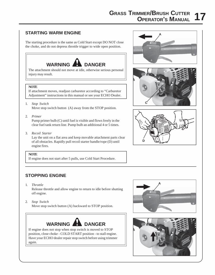
1. Stop SwitchMove stop switch button (A) away from the STOP position.
2. PrimerPump primer bulb (C) until fuel is visible and flows freely in theclear fuel tank return line. Pump bulb an additional 4 or 5 times.
3. Recoil StarterLay the unit on a flat area and keep movable attachment parts clearof all obstacles. Rapidly pull recoil starter handle/rope (D) untilengine fires.
NOTEIf engine does not start after 5 pulls, use Cold Start Procedure.
STOPPING ENGINE
1. ThrottleRelease throttle and allow engine to return to idle before shuttingoff engine.
2. Stop SwitchMove stop switch button (A) backward to STOP position.
WARNING DANGERIf engine does not stop when stop switch is moved to STOPposition, close choke - COLD START position - to stall engine.Have your ECHO dealer repair stop switch before using trimmeragain.
D
C
A
A
18
MAINTENANCE
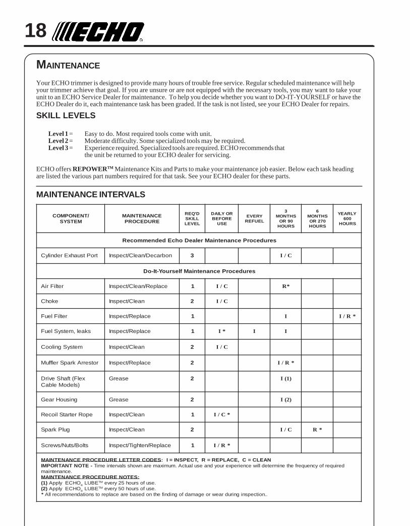
Your ECHO trimmer is designed to provide many hours of trouble free service. Regular scheduled maintenance will helpyour trimmer achieve that goal. If you are unsure or are not equipped with the necessary tools, you may want to take yourunit to an ECHO Service Dealer for maintenance. To help you decide whether you want to DO-IT-YOURSELF or have theECHO Dealer do it, each maintenance task has been graded. If the task is not listed, see your ECHO Dealer for repairs.
SKILL LEVELS
Level 1 = Easy to do. Most required tools come with unit.Level 2 = Moderate difficulty. Some specialized tools may be required.Level 3 = Experience required. Specialized tools are required. ECHO recommends that
the unit be returned to your ECHO dealer for servicing.
ECHO offers REPOWERTM Maintenance Kits and Parts to make your maintenance job easier. Below each task headingare listed the various part numbers required for that task. See your ECHO dealer for these parts.
MAINTENANCE INTERVALS
/TNENOPMOCMETSYS
ECNANETNIAMERUDECORP
D'QERLLIKSLEVEL
ROYLIADEROFEB
ESU
YREVELEUFER
3SHTNOM
09ROSRUOH
6SHTNOM
072ROSRUOH
YLRAEY006
SRUOH
serudecorPecnanetniaMrelaeDohcEdednemmoceR
troPtsuahxErednilyC nobraceD/naelC/tcepsnI 3 C/I
serudecorPecnanetniaMflesruoY-tI-oD
retliFriA ecalpeR/naelC/tcepsnI 1 C/I *R
ekohC naelC/tcepsnI 2 C/I
retliFleuF ecalpeR/tcepsnI 1 I *R/I
skael,metsySleuF ecalpeR/tcepsnI 1 *I I I
metsySgnilooC naelC/tcepsnI 2 C/I
rotserrAkrapSrelffuM ecalpeR/tcepsnI 2 *R/I
xelF(tfahSevirD)sledoMelbaC
esaerG 2 )1(I
gnisuoHraeG esaerG 2 )2(I
epoRretratSlioceR naelC/tcepsnI 1 *C/I
gulPkrapS naelC/tcepsnI 2 C/I *R
stloB/stuN/swercS ecalpeR/nethgiT/tcepsnI 1 *R/I
SEDOCRETTELERUDECORPECNANETNIAM NAELC=C,ECALPER=R,TCEPSNI=I:-ETONTNATROPMI deriuqerfoycneuqerfehtenimretedlliwecneirepxeruoydnaesulautcA.mumixameranwohsslavretniemiT
.ecnanetniam:SETONERUDECORPECNANETNIAM
)1( OHCEylppA ® EBUL MT .esufosruoh52yreve)2( OHCEylppA ® EBUL MT .esufosruoh05yreve
* ..noitcepsnignirudraewroegamadfognidnifehtnodesaberaecalperotsnoitadnemmocerllA
GRASS TRIMMER/BRUSH CUTTEROPERATOR'S MANUAL 19
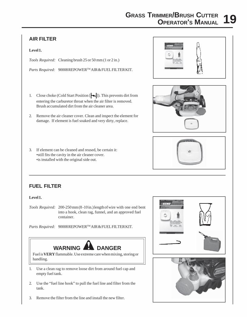
AIR FILTER
Level 1.
Tools Required: Cleaning brush 25 or 50 mm (1 or 2 in.)
Parts Required: 90008 REPOWERTM AIR & FUEL FILTER KIT.
1. Close choke (Cold Start Position [ ]). This prevents dirt from
entering the carburetor throat when the air filter is removed.Brush accumulated dirt from the air cleaner area.
2. Remove the air cleaner cover. Clean and inspect the element fordamage. If element is fuel soaked and very dirty, replace.
3. If element can be cleaned and reused, be certain it:•still fits the cavity in the air cleaner cover.•is installed with the original side out.
FUEL FILTER
Level 1.
Tools Required: 200-250 mm (8 -10 in.) length of wire with one end bentinto a hook, clean rag, funnel, and an approved fuelcontainer.
Parts Required: 90008 REPOWERTM AIR & FUEL FILTER KIT.
WARNING DANGERFuel is VERY flammable. Use extreme care when mixing, storing orhandling.
1. Use a clean rag to remove loose dirt from around fuel cap andempty fuel tank.
2. Use the “fuel line hook” to pull the fuel line and filter from thetank.
3. Remove the filter from the line and install the new filter.
20
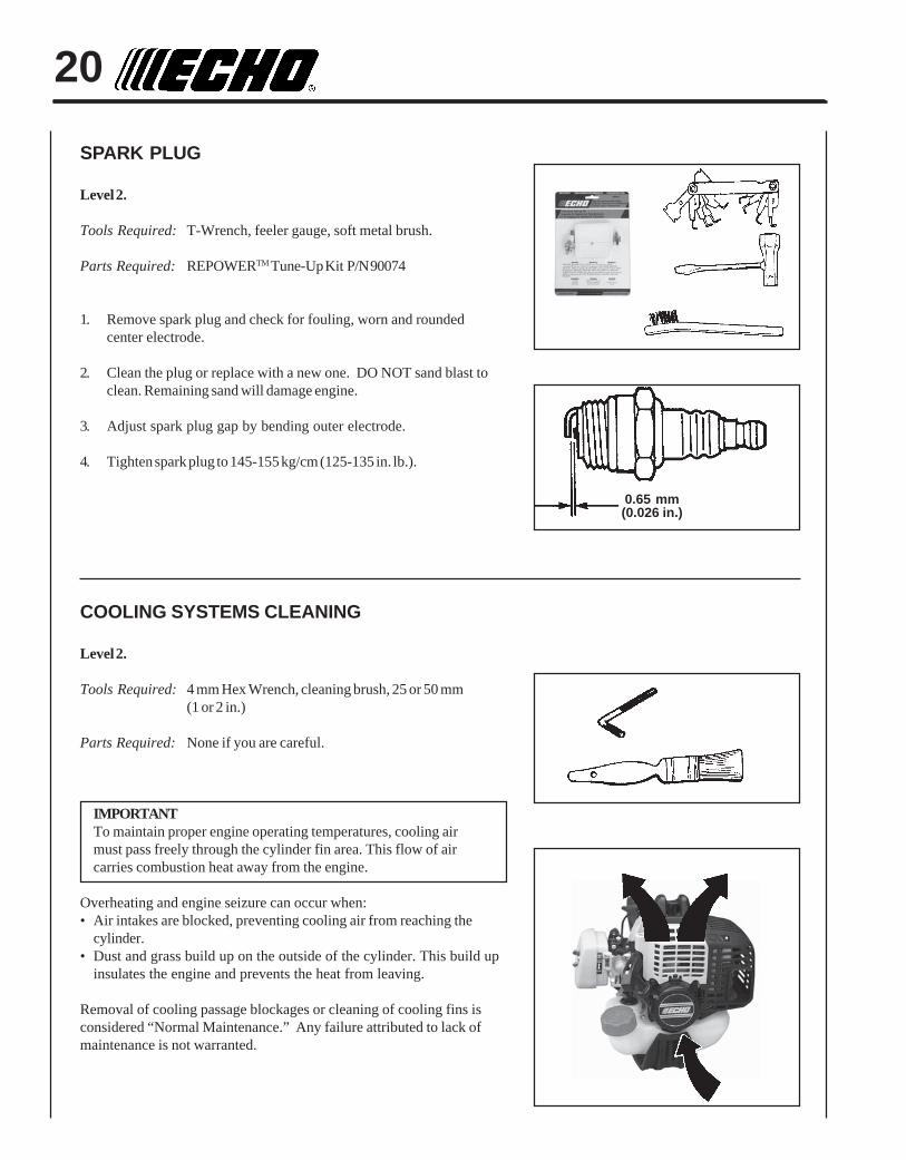
SPARK PLUG
Level 2.
Tools Required: T-Wrench, feeler gauge, soft metal brush.
Parts Required: REPOWERTM Tune-Up Kit P/N 90074
1. Remove spark plug and check for fouling, worn and roundedcenter electrode.
2. Clean the plug or replace with a new one. DO NOT sand blast toclean. Remaining sand will damage engine.
3. Adjust spark plug gap by bending outer electrode.
4. Tighten spark plug to 145-155 kg/cm (125-135 in. lb.).
COOLING SYSTEMS CLEANING
Level 2.
Tools Required: 4 mm Hex Wrench, cleaning brush, 25 or 50 mm(1 or 2 in.)
Parts Required: None if you are careful.
IMPORTANTTo maintain proper engine operating temperatures, cooling airmust pass freely through the cylinder fin area. This flow of aircarries combustion heat away from the engine.
Overheating and engine seizure can occur when:• Air intakes are blocked, preventing cooling air from reaching the
cylinder.• Dust and grass build up on the outside of the cylinder. This build up
insulates the engine and prevents the heat from leaving.
Removal of cooling passage blockages or cleaning of cooling fins isconsidered “Normal Maintenance.” Any failure attributed to lack ofmaintenance is not warranted.
0.65 mm(0.026 in.)
GRASS TRIMMER/BRUSH CUTTEROPERATOR'S MANUAL 21
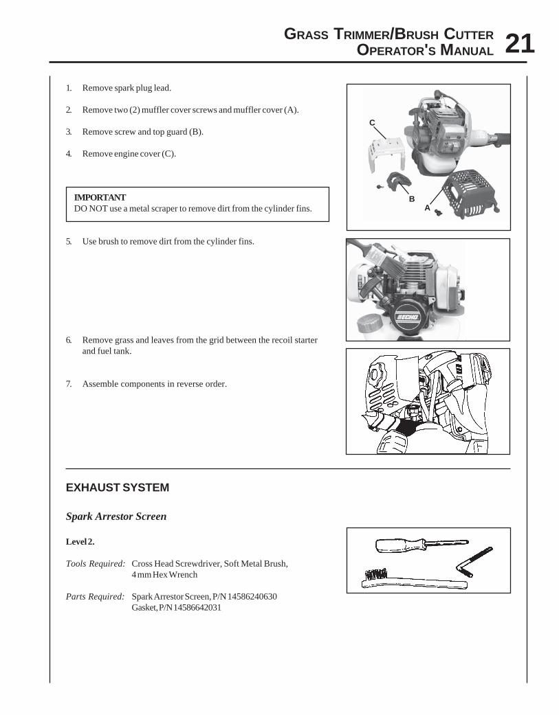
1. Remove spark plug lead.
2. Remove two (2) muffler cover screws and muffler cover (A).
3. Remove screw and top guard (B).
4. Remove engine cover (C).
IMPORTANTDO NOT use a metal scraper to remove dirt from the cylinder fins.
5. Use brush to remove dirt from the cylinder fins.
6. Remove grass and leaves from the grid between the recoil starterand fuel tank.
7. Assemble components in reverse order.
EXHAUST SYSTEM
Spark Arrestor Screen
Level 2.
Tools Required: Cross Head Screwdriver, Soft Metal Brush,4 mm Hex Wrench
Parts Required: Spark Arrestor Screen, P/N 14586240630Gasket, P/N 14586642031
AB
C
22
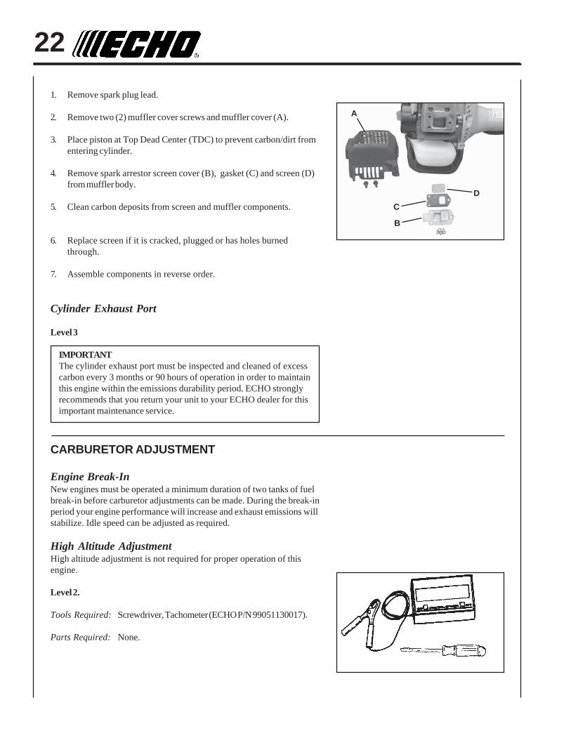
1. Remove spark plug lead.
2. Remove two (2) muffler cover screws and muffler cover (A).
3. Place piston at Top Dead Center (TDC) to prevent carbon/dirt fromentering cylinder.
4. Remove spark arrestor screen cover (B), gasket (C) and screen (D)from muffler body.
5. Clean carbon deposits from screen and muffler components.
6. Replace screen if it is cracked, plugged or has holes burnedthrough.
7. Assemble components in reverse order.
Cylinder Exhaust Port
Level 3
IMPORTANTThe cylinder exhaust port must be inspected and cleaned of excesscarbon every 3 months or 90 hours of operation in order to maintainthis engine within the emissions durability period. ECHO stronglyrecommends that you return your unit to your ECHO dealer for thisimportant maintenance service.
CARBURETOR ADJUSTMENT
Engine Break-InNew engines must be operated a minimum duration of two tanks of fuelbreak-in before carburetor adjustments can be made. During the break-inperiod your engine performance will increase and exhaust emissions willstabilize. Idle speed can be adjusted as required.
High Altitude AdjustmentHigh altitude adjustment is not required for proper operation of thisengine.
Level 2.
Tools Required: Screwdriver, Tachometer (ECHO P/N 99051130017).
Parts Required: None.
D
A
B
C
GRASS TRIMMER/BRUSH CUTTEROPERATOR'S MANUAL 23
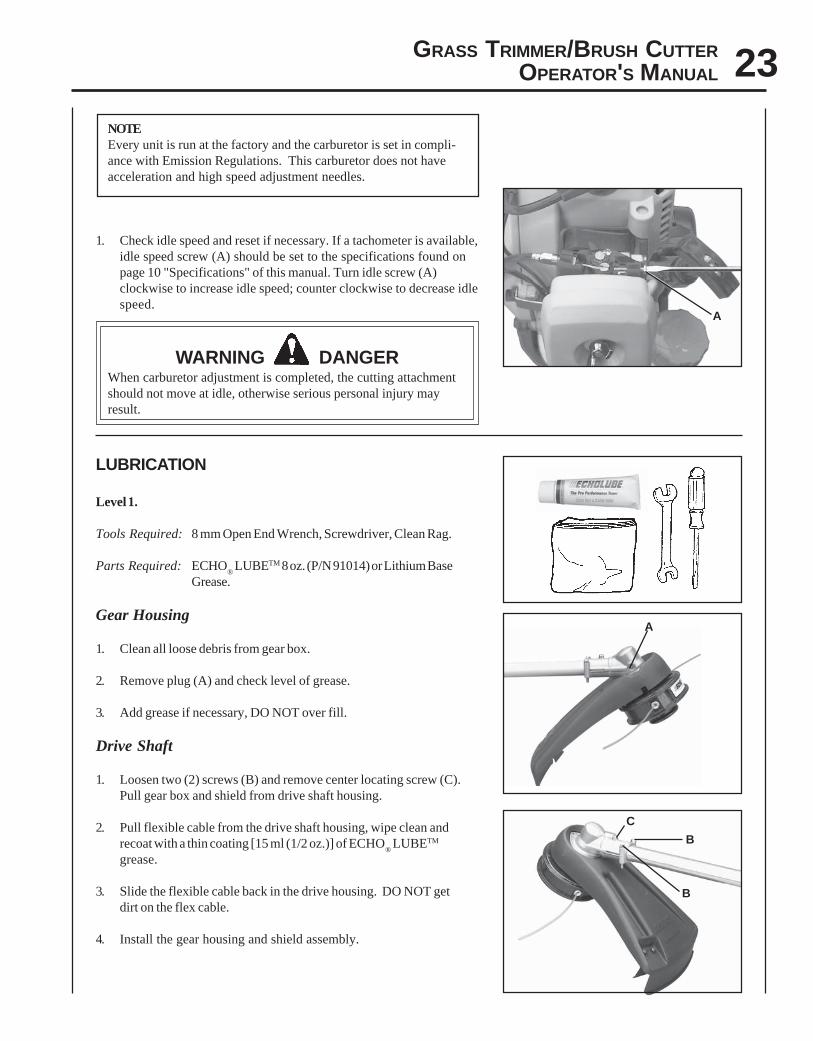
NOTEEvery unit is run at the factory and the carburetor is set in compli-ance with Emission Regulations. This carburetor does not haveacceleration and high speed adjustment needles.
1. Check idle speed and reset if necessary. If a tachometer is available,idle speed screw (A) should be set to the specifications found onpage 10 "Specifications" of this manual. Turn idle screw (A)clockwise to increase idle speed; counter clockwise to decrease idlespeed.
WARNING DANGERWhen carburetor adjustment is completed, the cutting attachmentshould not move at idle, otherwise serious personal injury mayresult.
LUBRICATION
Level 1.
Tools Required: 8 mm Open End Wrench, Screwdriver, Clean Rag.
Parts Required: ECHO® LUBETM 8 oz. (P/N 91014) or Lithium Base
Grease.
Gear Housing
1. Clean all loose debris from gear box.
2. Remove plug (A) and check level of grease.
3. Add grease if necessary, DO NOT over fill.
Drive Shaft
1. Loosen two (2) screws (B) and remove center locating screw (C).Pull gear box and shield from drive shaft housing.
2. Pull flexible cable from the drive shaft housing, wipe clean andrecoat with a thin coating [15 ml (1/2 oz.)] of ECHO
® LUBETM
grease.
3. Slide the flexible cable back in the drive housing. DO NOT getdirt on the flex cable.
4. Install the gear housing and shield assembly.
AA
A
B
C
B
24
NYLON LINE REPLACEMENT
Level 1.
Parts Required: ECHO 0.095 in. Nylon Trimmer Line 6 m (20 ft.) long.
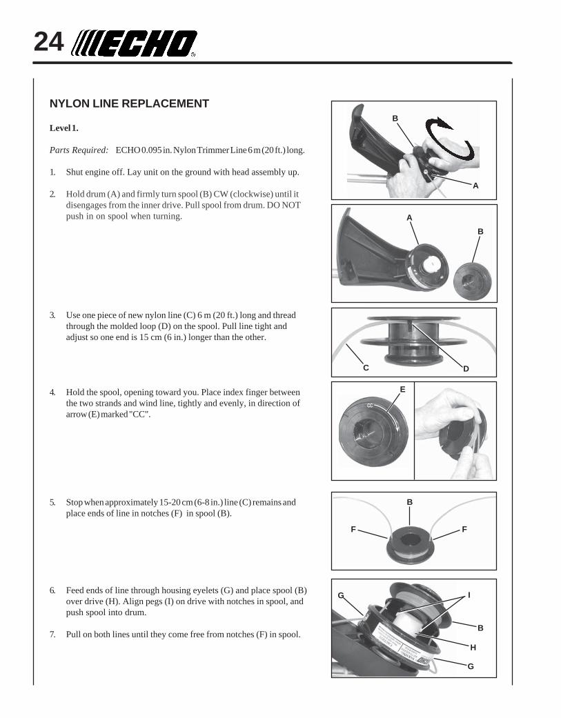
1. Shut engine off. Lay unit on the ground with head assembly up.
2. Hold drum (A) and firmly turn spool (B) CW (clockwise) until itdisengages from the inner drive. Pull spool from drum. DO NOTpush in on spool when turning.
3. Use one piece of new nylon line (C) 6 m (20 ft.) long and threadthrough the molded loop (D) on the spool. Pull line tight andadjust so one end is 15 cm (6 in.) longer than the other.
4. Hold the spool, opening toward you. Place index finger betweenthe two strands and wind line, tightly and evenly, in direction ofarrow (E) marked "CC".
5. Stop when approximately 15-20 cm (6-8 in.) line (C) remains andplace ends of line in notches (F) in spool (B).
6. Feed ends of line through housing eyelets (G) and place spool (B)over drive (H). Align pegs (I) on drive with notches in spool, andpush spool into drum.
7. Pull on both lines until they come free from notches (F) in spool.
D
I
B
A
C
G
G
FF
B
B
B
A
H
E
CC
GRASS TRIMMER/BRUSH CUTTEROPERATOR'S MANUAL 25
8. Hold drum (A) firmly and turn spool (B) CCW (counterclockwise)until it stops. DO NOT push in on spool when turning.
9. Pull both lines out and trim to cut-off knife length.
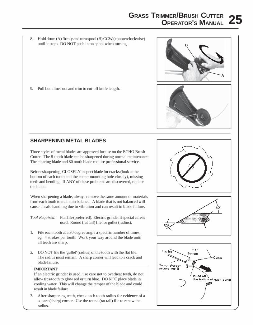
SHARPENING METAL BLADES
Three styles of metal blades are approved for use on the ECHO BrushCutter. The 8-tooth blade can be sharpened during normal maintenance.The clearing blade and 80 tooth blade require professional service.
Before sharpening, CLOSELY inspect blade for cracks (look at thebottom of each tooth and the center mounting hole closely), missingteeth and bending. If ANY of these problems are discovered, replacethe blade.
When sharpening a blade, always remove the same amount of materialsfrom each tooth to maintain balance. A blade that is not balanced willcause unsafe handling due to vibration and can result in blade failure.
Tool Required: Flat file (preferred). Electric grinder if special care isused. Round (rat tail) file for gullet (radius).
1. File each tooth at a 30 degree angle a specific number of times,eg. 4 strokes per tooth. Work your way around the blade untilall teeth are sharp.
2. DO NOT file the 'gullet' (radius) of the tooth with the flat file.The radius must remain. A sharp corner will lead to a crack andblade failure.
IMPORTANTIf an electric grinder is used, use care not to overheat teeth, do notallow tips/tooth to glow red or turn blue. DO NOT place blade incooling water. This will change the temper of the blade and couldresult in blade failure.
3. After sharpening teeth, check each tooth radius for evidence of asquare (sharp) corner. Use the round (rat tail) file to renew theradius.
B
A
26
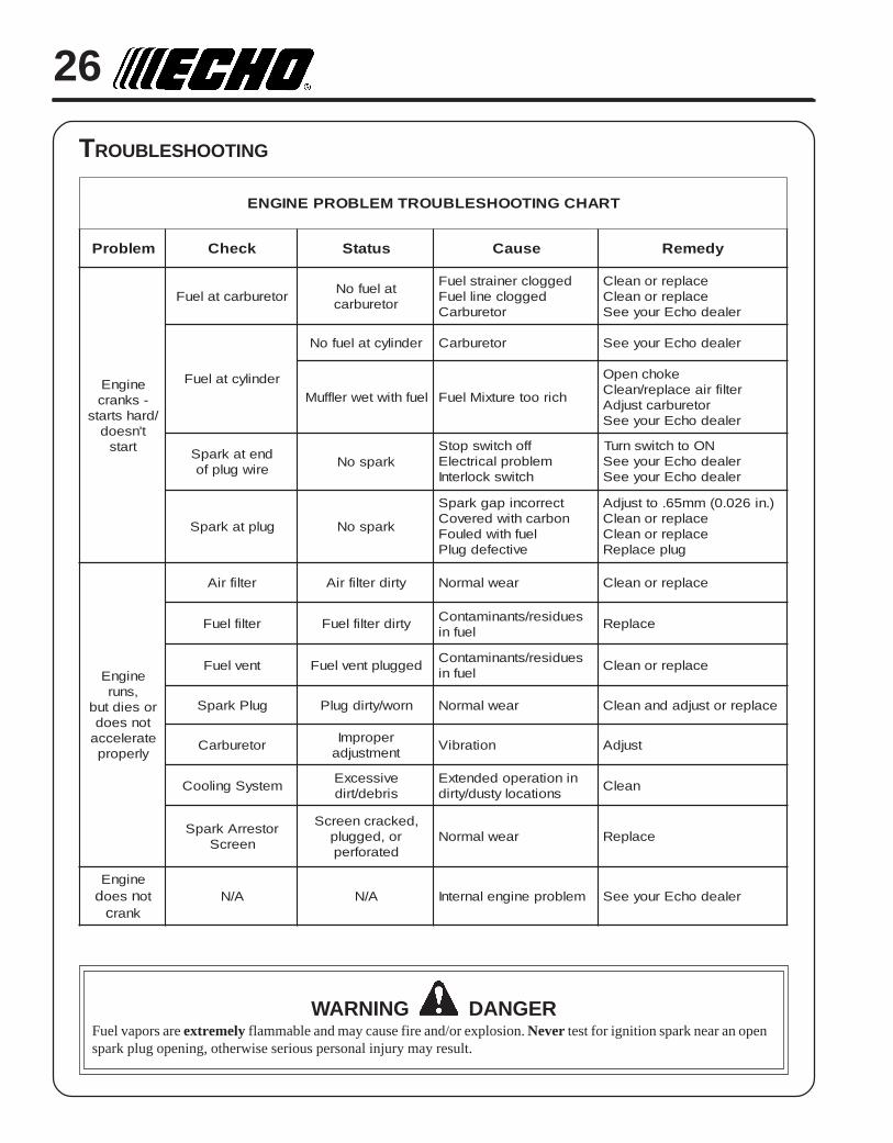
TROUBLESHOOTING
WARNING DANGERFuel vapors are extremely flammable and may cause fire and/or explosion. Never test for ignition spark near an openspark plug opening, otherwise serious personal injury may result.
TRAHCGNITOOHSELBUORTMELBORPENIGNE
melborP kcehC sutatS esuaC ydemeR
enignE-sknarc
/drahstratst'nseod
trats
roterubractaleuF taleufoNroterubrac
deggolcreniartsleuFdeggolcenilleuF
roterubraC
ecalperronaelCecalperronaelC
relaedohcEruoyeeS
rednilyctaleuF
rednilyctaleufoN roterubraC relaedohcEruoyeeS
leufhtiwtewrelffuM hcirooterutxiMleuF
ekohcnepOretlifriaecalper/naelC
roterubractsujdArelaedohcEruoyeeS
dnetakrapSeriwgulpfo krapsoN
ffohctiwspotSmelborplacirtcelE
hctiwskcolretnI
NOothctiwsnruTrelaedohcEruoyeeSrelaedohcEruoyeeS
gulptakrapS krapsoN
tcerrocnipagkrapSnobrachtiwderevoC
leufhtiwdeluoFevitcefedgulP
).ni620.0(mm56.ottsujdAecalperronaelCecalperronaelC
gulpecalpeR
enignE,snur
roseidtubtonseodetarelecca
ylreporp
retlifriA ytridretlifriA raewlamroN ecalperronaelC
retlifleuF ytridretlifleuF seudiser/stnanimatnoCleufni ecalpeR
tnevleuF deggulptnevleuF seudiser/stnanimatnoCleufni ecalperronaelC
gulPkrapS nrow/ytridgulP raewlamroN ecalperrotsujdadnanaelC
roterubraC reporpmItnemtsujda noitarbiV tsujdA
metsySgnilooC evissecxEsirbed/trid
ninoitarepodednetxEsnoitacolytsud/ytrid naelC
rotserrAkrapSneercS
,dekcarcneercSro,deggulp
detarofrepraewlamroN ecalpeR
enignEd seo n to
c knarA/N A/N melborpenignelanretnI relaedohcEruoyeeS
GRASS TRIMMER/BRUSH CUTTEROPERATOR'S MANUAL 27
STORAGE
WARNING DANGERDuring operation the muffler or catalytic muffler and surrounding cover become hot. Always keep exhaust area clearof flammable debris during transportation or when storing, otherwise serious property damage or personal injury mayresult.
Long Term Storage (over 30 days)
Do not store your unit for a prolonged period of time (30 days or longer) without performing protective storage mainte-nance which includes the following:
1. Store unit in a dry, dust free place, out of the reachof children.
WARNING DANGERDo not store in enclosure where fuel fumes may accumulate or reach an open flame or spark.
2. Place the stop switch (A) in the "STOP" position.
3. Remove accumulation of grease, oil, dirt and debrisfrom exterior of unit.
4. Perform all periodic lubrication and services that arerequired.
5. Tighten all the screws and nuts.
6. Drain the fuel tank completely and pull the recoilstarter handle several times to remove fuel from thecarburetor.
7. Remove the spark plug and pour 7 cc (1/4 oz.) offresh, clean, two-stroke engine oil into the cylinderthrough the spark plug hole.
A. Place a clean cloth over the spark plug hole.
B. Pull the recoil starter handle 2-3 times to distributethe oil inside the engine.
C. Observe the piston location through the sparkplug hole. Pull the recoil handle slowly until thepiston reaches the top of its travel and leave itthere.
8. Install the spark plug (do not connect ignition cable).

ECHO, INCORPORATED400 OAKWOOD ROAD
LAKE ZURICH, IL 60047www.echo-usa.com
SERVICING INFORMATION
PARTSGenuine ECHO Parts and ECHO REPOWER™ Parts and Assemblies foryour ECHO products are available only from an Authorized ECHODealer. When you do need to buy parts always have the ModelNumber and Serial Number of the unit with you. You can find thesenumbers on the engine housing. For future reference, write them in thespace provided below.
Model No. _____________ SN. ____________
SERVICEService of this product during the warranty period must be performedby an Authorized ECHO Service Dealer. For the name and address ofthe Authorized ECHO Service Dealer nearest you, ask your retailer orcall: 1-800-432-ECHO (3246). Dealer information is also available on ourWeb Site. When presenting your unit for Warranty service/repairs,proof of purchase is required.
ECHO CONSUMER PRODUCT SUPPORTIf you require assistance or have questions concerning the application,operation or maintenance of this product you may call the ECHOConsumer Product Support Department at 1-800-673-1558 from 8:30 amto 4:30 pm (Central Standard Time) Monday through Friday. Beforecalling, please know the model and serial number of your unit to helpyour Consumer Product Support Representative.
WARRANTY REGISTRATIONYou may register your Echo equipment using the warranty registrationcard or register on-line at www.echo-usa.com. Registering provides adirect link between you and ECHO if we find it necessary to contactyou.
DEALER?Call
1-800-432-ECHOor
www.echo-usa.com
CONSUMER PRODUCTSUPPORT
1-800-673-15588:30 - 4:30 Mon - Fri C.S.T.
ADDITIONAL OR REPLACEMENT MANUALSSafety Manuals in English/Spanish or English/French are available, free of charge, from your ECHO dealer or atwww.echo-usa.com.Operator's and Parts Manuals are available by:• Downloading free from www.echo-usa.com• Purchasing from your Echo Dealer.• Manuals are available by sending a written request stating the model number and serial number of your Echo unit, part
number of the manual, your name and address, and mail to the address below.Safety Videos are available from your Echo dealer. A $5.00 shipping charge will be required for each video.
Available Parts Catalog
SRM-230/230S Serial Number 05001001 - 05999999 Part Number 99922203528