grass (gsm-r risk assessment): risk assessment … international freight traffic flows. ... the...
TRANSCRIPT

1
GRASS (GSM-R Risk ASSessment): Risk Assessment on High Speed GSM-R network
A Case Study: Roma-Napoli
Fabio Senesi, E.Marzilli, N.Filippini, D.Caronti, R.Malangone Rete Ferroviaria Italiana, Rome, Italy
1-Abstract
Within the framework of high speed / high capacity lines operated by ERTMS system (GSM-R, ETCS) a research has been carried out on the possible cause of degradation of GSM-R system, related risks and possible mitigations. Location of the critical zones from the propagation point of view, localization of the possible sources of degradation of the functionality of the system and sources of electromagnetic interference in GSM-R band have been identified. Analytic model of interference sources has been implemented and evaluation of the ‘out of service probability’ (Outage) of the system and consequences has been performed. Definition and impact of the possible countermeasures are reported. Definition of possible tests to carry out for study validation is reported. Analysis of the main sources of interference/unavailability has been implemented on the Roma-Napoli high speed line taken as a case study for the other high/high capacity lines.
2- ERTMS High Speed Project
The introduction of the ERTMS/ETCS in Italy runs parallel to and integrates with the HS/HC project involving the construction of a new pair of tracks running along the most important railway routes which currently absorb 40% of domestic traffic. These are the Milan-Naples backbone with a future extension to Reggio Calabria and the transversal Turin-Milan-Venice, linked to Lyon and Ljubljana as part of the Corridor 5 system indicated in the European Community transport plan. Additionally, planning is under way for the link between Genoa and the Po Valley, known as Crossing III, for the extension to Austria through the new Brenner tunnel and to Switzerland through the Gothard tunnel, as well as for the “two seas” Rotterdam-Genoa and the Berlin-Palermo interoperable corridors which will be discussed at a later stage.
The main aims of the HS/HC project are to transform the Italian railway network into a high-speed/high-capacity system (with the possibility of dedicated passenger and freight traffic) with an overall capacity of more than twice current capacity, to upgrade and specialise existing lines for local, regional and freight transport, to enhance the effectiveness of existing lines in order to create numerous interconnections for ports, interports and airports, and to change the functional structure of metropolitan areas by reorganising urban transport and integrating domestic and international freight traffic flows. Figure 2.1 below shows the Italian HS/HC project as it is currently planned, together with journey time objectives between the main cities involved. The current implementation timetable for the HS/HC lines are described in Figure 2.2 which also includes a diagram of their interconnections with the urban
3-Telecommunications System
GSM-R The GSM-R system used to connect the ETCS Trackside Subsystem to the Trainborne Subsystem for the transfer of interoperable train separation information (via the EURORADIO protocol for the safety applications and messages envisaged by UNISIG specifications) for HS/HC lines comprises the switching subsystem (NSS) and the transmission subsystem (BSS). The switching subsystem (NSS), located at the HS/HC PC, comprises the following pieces of equipment:
• HLR / AUC (Home Location Register, Authentication Centre): -The HLR is a database containing all the information required to manage user profiles and mobility functions.
2
-AUC is a functional unit which calculates the parameters used to authenticate mobile users and codify the signal.
• MSC / VLR (Mobile Switching Centre / Visitor Location Register). -The MSC switches and manages calls from and to the mobile terminals. -The VLR is a database containing information about the mobile users in transit.
• IWF (Interworking Functions) acts as the interface between the GSM- R network and the ISDN network • IN (Intelligent Network). Provides services / functions such as Functional Addressing (FA) and Location Dependent Addressing
(LDA) • SMSC (Short Message Centre).
Used to transmit short text messages and icons.
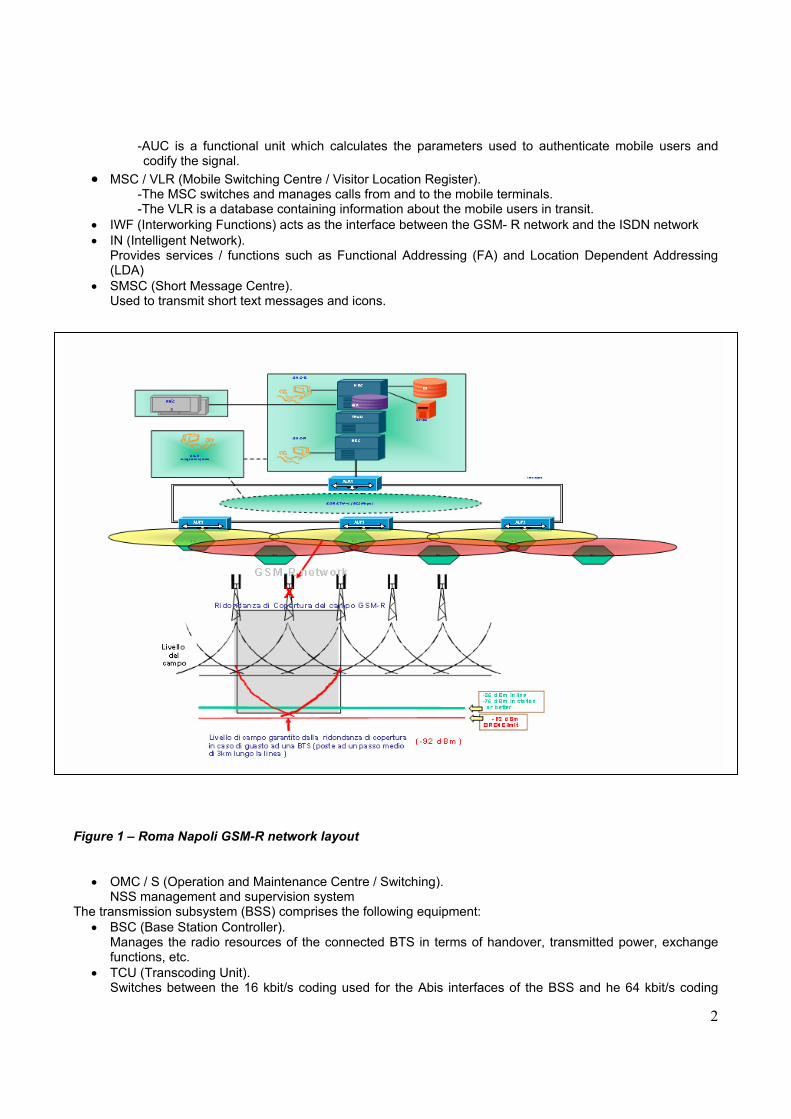
Figure 1 – Roma Napoli GSM-R network layout
• OMC / S (Operation and Maintenance Centre / Switching). NSS management and supervision system
The transmission subsystem (BSS) comprises the following equipment: • BSC (Base Station Controller). Manages the radio resources of the connected BTS in terms of handover, transmitted power, exchange
functions, etc. • TCU (Transcoding Unit). Switches between the 16 kbit/s coding used for the Abis interfaces of the BSS and he 64 kbit/s coding

3
used for the A interface of the NSS. • OMC / R (Operation and Maintenance Centre / Radio). Service and maintenance centre (CEM) controlling one or more BSC. • BTS (Base Transceiver Stations).
Provides the radio channels for communication between the mobile stations (MS) in the cell and the network.
There are approximately 60 BTS for the Rome-Naples line, including interconnections with the conventional line. All the radio components of the GSMR operate in the frequency band (4 MHz) reserved for UIC applications:
• 876 - 880 MHz up-link section; • 921 - 925 MHz down-link section,
with mixed FDMA/TDMA (Frequency / Time Division Multiple Access), 19 carriers are used in this band, each of which can carry up to eight channels (bandwidth 200khz). Main requirement to which system GSM-R for railway applications must comply with are EIRENE (European Integrated Railway Radio to you Enhanced Network) [ EIRENE Web site, http://gsm-r.uic.asso.fr/eirene.html ] and requirements of fixed network (performances of coverage, handover and selection of cell, time of logon, delays of transmission and probability of error etc.) and requirement of mobile terminal in [ "UIC Project EIRENE: Functional Requirements Specification ", v. 7.0, 17 May 2006], [ "UIC Project EIRENE: System Requirements Specification ", v. 15.0, 17 May 2006]. By the point of view of the coverage probability the following values must be reached on the railway high speed lines: probability of coverage of 95% with a level of cover of 38.5 dB μV/m (-98 dBm) for vocal applications; probability of coverage of 95% with a level of coverage of 41.5 dB μV/m (-95 dBm) on lines with smaller or equal speeds up to 220Km/h. The TLC support of the GSM-R for ERTMS applications should be considered as “open”, according to the definition in EN 50159-2 “Railway Applications: Requirements for Safety-Related Communication in Open Transmission Systems”. The safety and protection functions are therefore implemented “outside” the GSM-R via the Euroradio protocol. The BTS are fitted with two to four RF carriers to which the communication channels supporting all the services are allocated in TDMA technology. Priority functions (eMLLP) for vital ETCS and emergency applications are also provided. This makes it possible to give an ETCS data traffic call priority over a voice call. For the first time in European railway applications, the GSM-R system on the Rome-Naples line interfaced an NSS and a BSS provided by different suppliers, Siemens and Nortel respectively (IOT tests). This has allowed full integration between the national GSM-R network of the conventional RFI network and the HS/HC GSM-R network13.
4- GRASS (GSM Risk ASSesment) project
Provided the general GSM-R principles and architecture mentioned in the previous paragraph, it emerges clearly the necessity to carry out an activity of risk analysis of ‘un-availability’ when GSM-R is used for critical applications linked to traffic control, and signalling. The GRASS (GSM-R Risk ASSessment)"Risk assessment" project refers on GSM-R for railway ERTMS Italian High Speed applications. Particularly a case-study has been carried out on the ERTMS high speed Rome-Naples line. GRASS project did help point out: locations of the critical zones from the propagative point of view; location of the possible sources of degradation of the functionality of the system and sources of electromagnetic interference in band GSM-R band; analytic modelisation of interference sources; evaluation of the probability of out of service (Outage) of the system and consequently of its operating time; definition and impact of the possible countermeasures; definition of one list of possible tests to carry out for the evaluation study.

4
5-Analysis of the main sources of interference/un-availability PHASE 3 RISK ANALYSIS RFI drew up a Preliminary Hazard Analysis (PHA) in order to define the specifications of the ETCS level 2 system requirements for the HS/HC sections in Italy (SRS vol.1). Consorzio Saturno then used this document as input for performing a system level Hazard and Risk Analysis and issue subsystem requirement specifications. Regulatory mitigation, approved by the Ministry of Transport, was applied to 30% of the 250 hazards identified. The ensuing Hazard Analysis was conducted by a mixed Team of RFI and supplier experts, co-ordinated by Consorzio Saturno. The procedure began by analysing the functions involved in the ERTMS/ETCS system and identifying the hazards deriving from the failure or partial activation of these functions. The hazards identified were entered in the hazard log which was kept up to date throughout the project and will continue to be so by the operator during operations. System FMEA and FTA analysis The System FMEA (Failure Mode And Effects Analysis). analysis is based on the “Functional Model” used during the Hazard Analysis and Risk Assessment and examines the causes and effects of the particular system level failure modes from which Hazards are derived. The System FTA (Fault Tree Analysis) activity defines the System HA (Hazard Analysis) and FMEA in the form of a chart and, starting from the generic Top-Hazard, works down the entire “effect-cause” chain, passing through the various Hazards, as identified in the Hazard Analysis and Risk Assessment phase, until it identifies their generic Functional causes. The System FMEA and FTA activities are then compared with the applicable legislative documentation issued at European level (UNISIG Subset-091, in particular), in order to increase confidence in the thoroughness of the Hazard identification activities performed. During the final assessment phase, the Risk Analysis process for the entire signalling system was evaluated. Finally, a document in which the system Hazard Failure Rate (HFR) was calculated according to UNISIG specifications and the TSIs was drawn up. RFI also performed a preliminary analysis of the risks connected with the Security of the technological signalling infrastructure, according to BS 77 99 which defines the activities that can be schematised in a Risk Analysis and Risk Management. A Gap Analysis on the possible threats and appropriate countermeasures was also performed. The possible sources of intrusion of electromagnetic field sources on the GSM-R network governing the HS/HC sections were also analysed in this context. The Security Analysis included an independent Risk Assessment of the GSM-R wireless network used for High Speed (HS) railway applications, performed by suppliers together with the University of Pisa. The following were the subject of detailed analysis: • Identification of critical propagation zones • Localisation of possible sources of system functionality degrading and of non-system sources of
electromagnetic interference in the GSM-R band • Analytical modelling of sources of interference • Estimate of the probabilities of system outage and the relative consequences on operating time • Definition and impact of possible countermeasures • Definition of a list of possible tests to perform in order to validate the study
The following were identified: • List of TV transmitters • Interference from TV channels • Interference from GSM 900 • Interference from RADAR
and the “Critical Points”: sections of line subject to minimum field levels, even though they exceed the threshold established in EIRENE specifications. In these cases, the effect of non-system radio frequency interference, together with channel fading phenomena and, if relevant to that section, and Handover procedures was assessed.

5
Figure 2 - Example of an electromagnetic field map used to analyse possible sources of electromagnetic interference on the GSM-R network for HS/HC signalling.
-130
-120
-110
-100
-90
-80
-70
-60
-50
-40
-30
-20
-10
0
Mea
sure
d Fi
eld
Leve
l, [d
bm]
4.03.53.02.52.01.51.00.50.0
Distance from Site 7, [km]
Site 6bis - 923.0 MHz Site 7 - 922.4 MHz Site 8 - 923.8 MHz Site 9 - 921.2 MHz Threshold -92 dBm Threshold -95 dBm Threshold -98 dBm
Site 7 -> Site 8
BTS di partenza della coppia
BTS di arrivodella coppia
BTS precedente la coppia
BTS successiva alla coppia
Figure 2.bis Measured Field Level

6
As an example a part of measures related to the level of the electromagnetic field received (RXLev), expressed in dBm, along the piece of railway line comprised between the BTS 7 and BTS 8 of the draft is reported.
6-Test site and measures
The measures and the simulations carried out from Sirti corporation from km the 11,902 to km the 196,662 care the radio-electric coverage along the line and show the fulfilment of EIRENE specifications. In particular: - in nominal working condition of all BTS the field does not come down under the threshold of -92 dBm for 95% of the collected standard specimen data. The effects of the interferences on the performances of railway system GSM-R in terms of BER are evaluated, using well known curves previously calculated in the GSM-R specialistic literature. In particular, at first BER(‘within system’) due to the interferences is estimated, from adjacent channel (ACI) and Co-channel (CCI) on the
base of ( )aC I e ( )cC I
ratio coming from field tracing. Later on, it is estimated the effect on BER due to the interferences from part of the base stations E-GSM (‘external to system’). Finally, on the base of simplified statistical models, it is carried out an evaluation of out-of-service probability (Outage) of the system and consequently of its availability or operating time, due to the effect of the channel multipath. Out-of-Service probability (Outage): in order to reduce the interferences it is necessary to avoid that channels GSM-R used by signalling be immediately adjacent (in frequency) to those used from the BTS near high speed lines. To evaluate the out-of-service probability of the system is equivalent to determine with which probability the received power comes down under one determined threshold. Similarly, it is possible to estimate with which probability the signal/noise ratio to receiver GSM-R is inferior to the threshold that determines the BER critic value. Interference or degradation system factors: GSM Handover It has been observed that all HO on the line are by inner-BSC and, therefore managed completely from the only responsible BSC of all the present BTS. It has been calculated that the frequency of HO along the line is much elevated (one every 48 second ones to 300 Km/h). He turns from the analysis that approximately 70% of the un availability is due to HO event Other kind of interference sources:Doppler Shift , Doppler Spread, Interference GSM 900, Interference by TV, Interference by RADAR, Interference by Radio FM, Tunnel propagation Multipath, Meteo event . The Out-of-Service-Probablility due to Multipath event is contained within a value of approximately 12 dB, in the hypothesis in which the apparatus of reception uses techniques of evaluation/equalization of the efficient radio channel. The combined use of Reception in Diversity Spaces and Smart Antennas appears a fundamental factor in the increment of the performances of system GSM-R, in particular of its reliability and QoS. The tests indicated are apt to the validation of the adopted model of propagation and the countermeasures suggested for the reduction of the risk factors and un availability.
7- Test plan
Interfaces and test system architecture
On ERTMS high speed railway signalling application GSM-R carries safety critical data related to the control and the automatic protection of train (ATC/ATP), and of other not safety critical type (phone, emergency, messages ). GSM-R platform puts in communication the EVC (on – board sub-system) with the RBC that is the trackside command & control ETCS sub-system for ATC functions. Between GSM-R and the EVC/RBC is interposed the Euroradio subsystem for safety encryption process.

7
The Fig. 3 describes the model of communication.
Fig. 3 – GSM-R sub-system within EVC-RBC chain
The performances of GSM-R have to be estimated between the Ifix interfaces and IUm since such feature of the chain is of responsibility of single net GSM-R while the performances "end to end" would have to be estimated between the interfaces Igsm and Ifix. In truth, in order to analyze the behavior of GSM-R and the communications "end to end" based on GSM-R one needs to use one structure like that one described in the Fig. 4. The performances tied exclusively to GSM-R (called "network" in the continuation of the document) have been estimated between the IUm interfaces and Ifix(t) and measured on the IUm interface while those tied to applications "end to end" based on GSM-R have been estimated between the interfaces Igsm(t) and Ifix(t) and measured on the Igsm(t) interface.
Fig. 4 – Test system architecture
Such methodology of measure introduces some degradations not easy quantifiable on the performances measured and consequently regarding what it will be the operation of the communications end to end in system ETCS/ERTMS. In order to define and to organize the program of execution of the measures on the GSM-R nework, tests have been subdivided in various classes, according to the parameter to measure. Phase 1: preliminary tests of base GSM-R (voice and data), Mobile Switching side and network side (as an example, qualitative verification of the start-up procedure or tests on the calls voice, etc); Phase 2: Measures of time-related parameters, quality of service, from the "end to end",point of view. As we already pointed out the indications brought back in the present document are only applied to Phase 2 measures.

8
Fig. 5 – Test sequence
8- Conclusions and future perspectives
The main results of this study are:
• some of interference/un-availability sources like RADAR, radios FM, the phenomenon of attenuation for propagation in gallery and for meteorological phenomena, they can be considered in first approximation not affecting the railway service;
• the emissions of E-GSM and TV represent potential interferences towards GSM-R; however, along the considered lines the GSM-R signal/noise ratio has been proven to be sufficiently high to not affect the railway service;
• the combined use of techniques of reception in space-diversity space (RD) and adaptive antennas Array (SA-AA) appears a fundamental factor in the increment of the performances in terms of reliability and QoS of system GSM-R, in particular for the reduction of the handover and fading by multipath;