graphene d9.5 final... · showing very high capacity and strongly enhanced stability. for instance,...
TRANSCRIPT

Project funded by the European Commission under grant agreement n°604391
GRAPHENE Graphene-Based Revolutions in ICT and Beyond
Combination of CP and CSA
WP9 Energy applications
Deliverable D9.5: “Final report”
Main Author(s): E. Quesnel, F. Roux, CEA
V. Pellegrini, IIT
Due Date of Deliverable: M30
Actual submission date: M30
Dissemination level: PU

GRAPHENE D9.5 29 March 2016 2 / 53
LIST OF CONTRIBUTORS
Partner Acronym Partner Name Name of the contact
3 CNR CNR-NANO S. Heun and V. Tozzini
11 CEA Commissariat à l’Energie Atomique
et aux Energies Alternatives.
E. Quesnel, F. Roux, R.
Ramos and L. Simonin
19 TRT Thales France P. Bondavalli
28 UCAM University of Cambridge C. Grey, M. Tsiamtsouri
36 TEIC Technological Educational Institute
of Crete E. Kymakis
37 UOXF University of Oxford F. Giustino, G. Volonakis
38 IIT Istituto Italiano di Tecnologia I. Moreels
39 CIC CIC energiGUNE Supercaps: R. Mysyk
Batteries: G. Singh
40 REP Repsol A. Paez Duenas
41 SU Sabanci University S. Alkan Gürsel
42 UMEA Umeå University A. Talyzin
43 FBK Fondazione Bruno Kessler Luigi Crema, Giorgio Speranza
Nadhira Laidani, Matteo Testi
44 TUDr Technical University of Dresden G. Seifert
65 NOKIA.UKL Nokia UK D. Wei
96 UCL University College London P.F. McMillan
97 Imperial Imperial College of Science M. Shaffer
98 Amalyst Amalyst Ltd D. Hodgson
99 UNIPD Universita degli studi di Padova V. Di Noto
100 UNIWARSAW Uniwersytet Warszawski P. Kulesza
101 BRETON BRETON SPA Z. Stefano
104 EPFL Ecole Polytechnique Federale de
Lausanne M. Graetzel
105 UTV Università degli studi di Roma Tor
Vergata Aldo Di Carlo
106 JHIPC J. Heyrovsky Institute of Physical
Chemistry, Prague Ladislav Kavan
107 G24 G24 Power Limited Kethinni G. Chittibabu

GRAPHENE D9.5 29 March 2016 3 / 53
TABLE OF CONTENTS 1 Deliverable Summary ....................................................................................................................4 2 Introduction ...................................................................................................................................7 3 Main achievements and results per topic .......................................................................................7
3.1 Photovoltaic applications (Task 9.1) ......................................................................................7 3.2 Battery applications (Task 9.2) ............................................................................................ 16 3.3 Supercapacitor applications (Task 9.2) ............................................................................... 26 3.4 Fuel cell applications (Task 9.3) .......................................................................................... 31 3.5 Hydrogen storage applications (Task 9.4) ........................................................................... 39 3.6 References ......................................................................................................................... 43 3.7 Dissemination activities (whole ramp-up phase period) ....................................................... 44

GRAPHENE D9.5 29 March 2016 4 / 53
1 Deliverable Summary
This report gives an overview of the research activities running within WP9 of the Graphene Flagship for the whole ramp-up phase. Some scientific details can be found in the report, many others in the publications listed at the end of report. The main achievements can be summarised as follows: Photovoltaics: Inorganic thin films: The work carried out led to the demonstration of graphene-based a-Si:H solar cells of 16 mm² active area with a PCE up to 1.4%. This result was achieved with 3 layers graphene electrodes provided by Graphenea and exhibiting a 200 Ω/sq resistivity. Despite this relatively modest PCE value, this result is among the best values published so far for such active a-Si:H solar cell area. Actually, the main bottleneck for the demonstration of larger area graphene based solar cells remains the low conductivity of graphene. In-situ doping experiments have been initiated and will be pursued as the main route to further reduce the resistivity of the graphene-based electrodes. Colloidal PV: based on click chemistry developed for that purpose, QD-graphene hybrid thin films with controlled properties were successfully synthesized. A proof-of-principle QD-based photovoltaic (PV) cell with the integration of the hybrid material was demonstrated showing a PCE up to 0.8% (active area: ~6mm2). Organic solar cells: Solution processable graphene (SPG) materials have been integrated in all the three major components of OPV devices resulting in a strong enhancement in solar cell performances: (i) using a laser-based patterning technique to control the transparency/resistivity of electrode, a PCE of 3.05% (4 mm²) was demonstrated which is the highest level reported so far for flexible OPV incorporating SPG graphene-based electrodes; (ii) the work-function of GO layers was controlled by (photo)chemical methods to perfectly match the HOMO (LUMO) levels of different donor (acceptor) polymers. Using such optimised hole/electron transport layers resulted in the highest reported PCE for graphene-based charge extraction layer OPV of 9.14% (4 mm²); (iii) a laser assisted chemical route was developed to provide graphene-based electron acceptor materials with tuneable band-gap and enable the highest reported PCE of 2.41% (4 mm²) for graphene-based active layers used in OPV. Finally, electron-cascade electron acceptor materials based either on graphene nanoflakes or other 2D material were used as a ternary compound inside the PV absorber to boost OPV efficiency: +18% PCE was demonstrated with graphene and +13% PCE with WS2 2D nanosheets decorated with plasmonic Au nanoparticles. Perovskite solar cells: At the cell level, addition of RGO and nitrogen-doped RGO both in perovskite and HTM led to demonstrate PCE of 18.67% (16 cm²), to be compared to 17.57% without rGO. At the demonstrator level, RGO and GO were used as charge extraction layers when coated on the m-TiO2 scaffolds or as a passivating layer between the perovskite and the HTM. Several mini-modules were demonstrated with PCE reaching 9.03% (100 cm²), 10.4% (60 cm²) and 11.5% (10 cm²). In all these cases, the incorporation of graphene materials yielded a relative increase of 10% up to 40% as compared to the reference devices without graphene. These (glass-glass) modules were encapsulated using G24 expertise. Dye-sensitized solar cells (DSSC): To replace scarce and costly Pt catalyst commonly used in this technology, graphene catalysts ink were spray coated on PET/ITO substrates. It was shown that once integrated into DSSCs, Graphene behaves as a quite good catalyst, with PCE reaching 3.4% (25 mm², 400 lux), half the values obtained with Pt. Batteries: Li-O2 batteries, cathodes: By using a highly porous RGO electrode in combination with redox mediator LiI in a DME-based electrolyte, it was demonstrated a Li-air battery with 93.2% energy efficiency (voltage gap limited to 0.2 V) and cycled more than 2000 times. Its specific energy of 5760 Wh/kg is more than 50 times greater than that of the classical graphite-based Li-ion batteries.
GRAPHENE D9.5 29 March 2016 5 / 53
Li-ion batteries, anodes: Various graphene-nanocrystal composite anodes were developed, all showing very high capacity and strongly enhanced stability. For instance, anodes based on a RGO conductive network on which Si nanoparticles are formed were shown to maintain a specific capacity of 1000 mAh/g after 30 charge/discharge cycles at 50 mA/g. Similar work conducted by another partner confirmed a specific capacity of the same order of magnitude (800 mAh/g at 50 mA/g rate) but with a stability maintained over more cycles (x100). Using a similar approach, SnO2/RGO composites were found to exhibit a specific capacity of 650 mAh/g at 50 mA/g with highly stable performances over 1000 cycles. Similarly, SnO2 nanoparticle-pillared RGO composite anodes were demonstrated to provide a specific capacity higher than 1000 mAh/g maintained after 30 charge/discharge cycles at 50 mA/g rate, which is much higher than theoretical capacity of bulk SnO2. The energy density of this electrode with respect to the Li counter electrode is 720 Wh/kg based on the mass of RGO/SnO2 composite at a power density of 40 W/kg with 80% retention after 100 cycles. For a deeper understanding of the charge/discharge mechanisms, NMR experiments were successfully validated for graphite electrodes. Work is now on going to monitor the Li intercalation mechanisms for graphene integrating Li-ion batteries. Na-ion batteries: exfoliation of Na2Ti3O7 has been carried out. After restacking with Na, a more disordered compound was obtained allowing to double the specific capacity (200 mAh/g at C/20 rate) compared to the pristine material. The energy density of the electrode with respect to Na counter electrode is 140 Wh/kg based on the mass of Na2Ti3O7 at a power of 10 W/kg with 95% retention after 20 cycles. As for Li-ion batteries, NMR is now being applied to monitor the underlying mechanisms of Na-ion batteries functioning (intercalation, metastable phases…). Demonstrators: Nokia benchmarked pure graphene electrodes from IIT, SnO2/RGO composites electrodes from CIC, as well as new CVD graphene electrode materials (plates, papers and cloths) from ALA Alliance Japan. Standard CR202 coin cells were manufactured using Li foil as counter electrode. Though CVD graphene provides the perfect layer interface, the best energy density remained below the graphite-based electrodes level for Li-ion batteries (100 Wh/g). Instead, these performances were outperformed using SnO2/RGO composites from CIC, reaching 440 mAh/g. At ITT, a full lithium-ion battery based on a graphene ink anode and a lithium iron phosphate cathode has been achieved demonstrating a specific capacity of 165 mAhg−1, an estimated energy density of about 190 Wh kg−1 and a stable operation for over 80 charge−discharge cycles was demonstrated. To the best of our knowledge, complete, graphene-based, lithium ion batteries having performances comparable with those offered by the present technology are rarely reported. Supercapacitors: RGO-based electrodes: by tuning the thermal reduction conditions of graphite/graphene oxides, competitive materials has been delivered for supercapacitor manufacturing, based on high electrolyte accessible surface. In alkaline aqueous electrolytes, the resistive contribution is below 25% of the voltage drop for ultrahigh current densities up to 200 A/g, giving an ultrafast electrochemical response. This led to power densities of up to 75 kW/kg, well above the limit of EDLC based on activated carbon (about 10-15 kW/kg). The thermal reduction of GO developed at temperatures below 1000°C can potentially be implemented in mass production. RGO and G-CNT mesoporous electrodes: in the first stages of the work conducted on this technological route, the adjustment of the GO/CNT ratio in water based suspensions deposited by spray-gun techniques led to supercapacitors with a power density up to 31 kW/kg. Further works in collaboration with IIT replaced GO by high quality exfoliated graphene in NMP. In this case, power densities increased to more than 90 kW/kg, due to the high conductivity of the high quality graphene. Nanocage-pillared RGO electrodes: nanopillars molecules (Ni-based M8L6 porphyrin-faced nanocage) were used successfully as spacers inserted between RGO layers. The gravimetric capacitance of the material obtained that way was 100 F/g, yielding an energy density of 16 Wh/kg that was however limited by the chemical decomposition of the cage molecules.

GRAPHENE D9.5 29 March 2016 6 / 53
Fuel cells: Low-Pt content fuel cells: graphene-based gas diffusion electrodes including GO, graphene-based nanocomposites, functionalized graphene, and graphene-carbon black hybrids, have been developed as a replacement of commercial carbon black used in PEM fuel cells. The target of 2 kW/g Pt for Pt utilization efficiency was achieved with two different solutions: electrosprayed nanocomposite electrodes (Pt/RGO/Vulcan XC-72): 2.2 kW/g Pt; and ethylene glycol reflux method of graphene-carbon black hybrid electrodes (Pt/RGO/Vulcan CX-72 (75:25)): 2.6 kW/g Pt. Pt-free CN-based fuel cells: different electrocatalysts (EC) with GRM-CN “core-shell” morphology were synthetized to overcome the oxygen reduction reaction (ORR), the main bottleneck in fuel cells. Two different Fe-Sn GRM-CN ECs were fabricated, electrochemically tested, and implemented in alkaline medium. Results showed that the main KPIs of project were overcome, i.e.: onset potential of Pt-free ECs not 100 mV lower than the Pt/C reference EC; 60.9% efficiency of the ORR for Pt-free EC reached (higher than the initial 50% target) and similar degradation of the onset potential of Pt-free EC and Pt/C EC over 15000 cycles. Significant progresses are ongoing in the demonstration of membrane electrode assemblies (MEAs) with conventional Pt/C and commercial anion exchange membranes. The production of Pt-free ECs from UNIPD to 10g batches has been demonstrated by BRETON, however with a somehow smaller ORR efficiency, and pre-industrial MEAs with active area of 50 cm² AEM have been fabricated and tested. CNG nanoflakes-based electrodes: a route for exfoliation of different graphitic carbon nitrides was developed that led to carbon nitride graphene nanoflakes with semiconducting properties. Once mixed with RGO, inks were obtained that could be loaded with a low amount of Pt, and tested as cathode and anode catalysts for PEM fuel cells. Improved performances were observed compared to Pt/GO- or Pt/CN- based inks; however, their ORR efficiency remained significantly lower than commercial Pt/C reference materials. H2 storage: High surface area GRM (physisorption): activated RGO scaffolds materials with specific area of 3400 m²/g (beyond the theoretical limit for pristine defect-free graphene) were obtained at UMEA by exfoliation procedures. The exceptional pore volume (2.2 cm3/g) allowed H2 uptake of 7.5wt% (saturated at 40-50 bar) at N2 temperature (77K), 4 wt% at CO2 temperature (193K) and 120 bar, and 1.2 wt% at room temperature and 120 bar. The experimental work was closely supported by theoretical studies by TUD. Metal decorated graphene (chemisorption): graphene-based powders and films were decorated with niobium oxide catalyst nanolayers using dry methods. The effect of hydrogenation of the decorated material was studied, which showed (though still preliminary at this stage) an H2 uptake linked to the graphene decoration extent. A new wet route to optimize the decoration and the stabilization of Mg and or Pd clusters on graphene flakes has started recently. For the upscaled production (up to 10g batches) of metal decorated graphene or GRM by wet processes, a reactor was specifically designed and is now being tested. H2 interaction with curved graphene: theoretical and experimental works have been carried out to understand and optimize the manipulation of graphene morphology at the nanometric level. Noteworthy, it was demonstrated that using Ti atoms pined on intentional defects on graphene surface, gravimetric densities up to 2.4 wt% at room temperature could be achieved. Dissemination: At the end of the flagship ramp-up phase, the list of publications (accepted and under submission) and participations to conferences demonstrates a very strong and large dissemination activity which can be summarized as follows: Photovoltaics: 37 papers, 25 talks, 1 patent Batteries and supercapacitors: 4 papers, 24 talks, 3 patents Fuel cells: 12 papers, 22 talks, 1 patent H2 storage: 24 papers, 37 talks.
GRAPHENE D9.5 29 March 2016 7 / 53
2 Introduction The objective of D9.5 report is to provide an overview of research activities running since the beginning of the ramp-up phase on 1st of October 2013 in WP9 of the Graphene Flagship.
3 Main achievements and results per topic
3.1 Photovoltaic applications (Task 9.1)
The objective is to develop graphene and graphene related materials (GRM) integration strategies to provide various photovoltaic (PV) technologies with new cell building blocks. It includes transparent and conductive electrodes, electron and hole transport layers as well as photovoltaic absorbers. The aim is to assess the interest of graphene and GRMs in thin films, organic as well as quantum dots and dye sensitized solar cells.
3.1.1 Inorganic thin film solar cells (CEA)
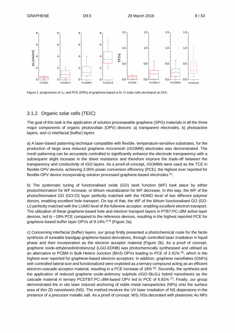
The task of CEA was focussed on using graphene as a transparent conductive electrode in a-Si:H solar cells on a glass substrate. The objectives were successively a) To make a proof of concept of a working device b) To improve the adhesion of graphene to the glass substrate c) To improve the sheet conductivity of graphene and resulting solar performance. a) A successful demonstration was first achieved with single layers of graphene provided by UCAM (1kΩ/sq, 98% transparency). Under standard conditions (AM1.5G spectra, 100 mW/cm²) they showed an open-circuit voltage (Voc) of ~800 mV comparable to the Voc of the reference cells; however the short circuit-current (Jsc) density was limited to values not higher than 0.6 mA/cm² (FLG1401-fig.1), which was considerably lower than the Jsc of the reference cells (ca. 8 mA/cm²). b) Several strategies were investigated to reduce the stress generated in the graphene by the solar cell stack. These included: reduction of the absorber thickness, use of an amorphous transparent back electrode, optimized cleaning procedure of the graphene and adhesion layers. Altogether, this yield an improvement of the Jsc up to 2 mA/cm² ((FLG1501A-fig.1) c) However the conductivity of graphene remains a strong bottleneck, and several routes were followed to decrease its value (ideally, lower than 100 Ω/sq): wet doping, dry doping, stacking of 3 layers. Wet doping experiments employed with HNO3 solutions. However, this chemical treatment seemed to be unstable at the process temperatures used for Si deposition and no increase in carrier concentration was clearly observed. To solve this issue, plasma doping, using doping atoms introduced during the Si deposition (in-situ doping) is expected to be much more stable. We have found that the carrier concentration (~1012 cm-2), as probed by Raman spectroscopy and Hall measurements, is not altered by the ion bombardment. Plasma conditions need to be further adjusted to increase the carrier concentration while preserving a sufficient mobility. The last route under investigation is the use of 3 layers graphene (3LG). To this aim, we have been supported by Graphenea, which provided us with 3LG transferred on glass. The sheet conductivity of these samples was ca. 200 Ω/sq, which was the best material we were able to use so far. The carrier density was about 2.1013 cm-2, and the mobility about 1700 cm²/(V.s). The main benefit was a huge increase of the Jsc up to 7 mA/cm² (FLG1501B- Fig.1). The power conversion efficiency (PCE) of the best solar cell is 1.4% which is the highest value reported so far for a 16 mm² a-Si:H solar cell. These results will be presented at the 31st EU PVSEC conference to be held in June 2016
GRAPHENE D9.5 29 March 2016 8 / 53
Figure 1: progression of Jsc and PCE (Eff%) of graphene-based a-Si :H solar cells developed at CEA.
3.1.2 Organic solar cells (TEIC)
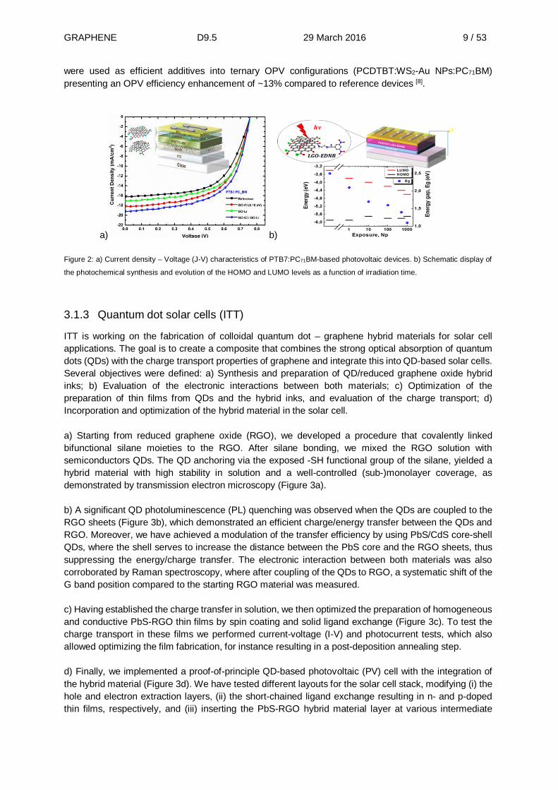
The goal of this task is the application of solution processeable graphene (SPG) materials in all the three major components of organic photovoltaic (OPV) devices: a) transparent electrodes, b) photoactive layers, and c) interfacial (buffer) layers a) A laser-based patterning technique compatible with flexible, temperature-sensitive substrates, for the production of large area reduced graphene micromesh (rGOMM) electrodes was demonstrated. The mesh patterning can be accurately controlled to significantly enhance the electrode transparency with a subsequent slight increase in the sheet resistance and therefore improve the trade-off between the transparency and conductivity of rGO layers. As a proof-of-concept, rGOMMs were used as the TCE in flexible OPV devices, achieving 3.05% power conversion efficiency (PCE), the highest ever reported for flexible OPV device incorporating solution processed graphene-based electrodes [1]. b) The systematic tuning of functionalised oxide (GO) work function (WF) took place by either photochlorination for WF increase, or lithium neutralization for WF decrease. In this way, the WF of the photochlorinated GO (GO-Cl) layer perfectly matched with the HOMO level of two different polymer donors, enabling excellent hole transport. On top of that, the WF of the lithium functionalised GO (GO-Li) perfectly matched with the LUMO level of the fullerene acceptor, enabling excellent electron transport. The utilization of these graphene-based hole and electron transport layers in PTB7:PC71BM active layer devices, led to ~19% PCE compared to the reference devices, resulting in the highest reported PCE for graphene-based buffer layer OPVs of 9.14% [2-4] (Figure 2a). c) Concerning interfacial (buffer) layers, our group firstly presented a photochemical route for the facile synthesis of tuneable bandgap graphene-based derivatives, through controlled laser irradiation in liquid phase and their incorporation as the electron acceptor material (Figure 2b). As a proof of concept, graphene oxide-ethylenedinitrobenzoyl (LGO-EDNB) was photochemically synthesised and utilised as an alternative to PCBM in Bulk Hetero Junction (BHJ) OPVs leading to PCE of 2.41% [5], which is the highest ever reported for graphene-based electron acceptors. In addition, graphene nanoflakes (GNFs) with controlled lateral size and functionalized were exploited as a ternary compound acting as an efficient electron-cascade acceptor material, resulting in a PCE increase of 18% [6]. Secondly, the synthesis and the application of reduced graphene oxide-antimony sulphide (rGO-Sb2S3) hybrid nanosheets as the cascade material in ternary PCDTBT:PC71BM-based OPV led to PCE of 6.81% [7]. Finally, our group demonstrated the in situ laser induced anchoring of noble metal nanoparticles (NPs) onto the surface area of thin 2D nanosheets (NS). The method involves the UV laser irradiation of NS dispersions in the presence of a precursor metallic salt. As a proof of concept, WS2 NSs decorated with plasmonic Au NPs
0
2
4
6
8Js
c [m
A/cm
²]
FLG1511-BFLG1508-DFLG1501-AFLG14010
2
4
6
8
0
2
4
6
8
0
2
4
6
8
0.0
0.5
1.0
1.5
Eff [
%]
FLG1511-BFLG1508-DFLG1501-AFLG14010.0
0.5
1.0
1.5
0.0
0.5
1.0
1.5
0.0
0.5
1.0
1.5
GRAPHENE D9.5 29 March 2016 9 / 53
were used as efficient additives into ternary OPV configurations (PCDTBT:WS2-Au NPs:PC71BM) presenting an OPV efficiency enhancement of ~13% compared to reference devices [8].
a) b)
Figure 2: a) Current density – Voltage (J-V) characteristics of PTB7:PC71BM-based photovoltaic devices. b) Schematic display of
the photochemical synthesis and evolution of the HOMO and LUMO levels as a function of irradiation time.
3.1.3 Quantum dot solar cells (ITT)
ITT is working on the fabrication of colloidal quantum dot – graphene hybrid materials for solar cell applications. The goal is to create a composite that combines the strong optical absorption of quantum dots (QDs) with the charge transport properties of graphene and integrate this into QD-based solar cells. Several objectives were defined: a) Synthesis and preparation of QD/reduced graphene oxide hybrid inks; b) Evaluation of the electronic interactions between both materials; c) Optimization of the preparation of thin films from QDs and the hybrid inks, and evaluation of the charge transport; d) Incorporation and optimization of the hybrid material in the solar cell. a) Starting from reduced graphene oxide (RGO), we developed a procedure that covalently linked bifunctional silane moieties to the RGO. After silane bonding, we mixed the RGO solution with semiconductors QDs. The QD anchoring via the exposed -SH functional group of the silane, yielded a hybrid material with high stability in solution and a well-controlled (sub-)monolayer coverage, as demonstrated by transmission electron microscopy (Figure 3a). b) A significant QD photoluminescence (PL) quenching was observed when the QDs are coupled to the RGO sheets (Figure 3b), which demonstrated an efficient charge/energy transfer between the QDs and RGO. Moreover, we have achieved a modulation of the transfer efficiency by using PbS/CdS core-shell QDs, where the shell serves to increase the distance between the PbS core and the RGO sheets, thus suppressing the energy/charge transfer. The electronic interaction between both materials was also corroborated by Raman spectroscopy, where after coupling of the QDs to RGO, a systematic shift of the G band position compared to the starting RGO material was measured. c) Having established the charge transfer in solution, we then optimized the preparation of homogeneous and conductive PbS-RGO thin films by spin coating and solid ligand exchange (Figure 3c). To test the charge transport in these films we performed current-voltage (I-V) and photocurrent tests, which also allowed optimizing the film fabrication, for instance resulting in a post-deposition annealing step. d) Finally, we implemented a proof-of-principle QD-based photovoltaic (PV) cell with the integration of the hybrid material (Figure 3d). We have tested different layouts for the solar cell stack, modifying (i) the hole and electron extraction layers, (ii) the short-chained ligand exchange resulting in n- and p-doped thin films, respectively, and (iii) inserting the PbS-RGO hybrid material layer at various intermediate

GRAPHENE D9.5 29 March 2016 10 / 53
positions in the n- and p-doped QDs. At present, the characteristics of best devices developed for the QD-only cell are: 1.4% power conversion efficiency, with fill factor (FF) of 44.7%, open-circuit voltage (Voc) of 0.36 V and short-circuit current density (Jsc) of 9.0 mA.cm-2. Incorporating the PbS-RGO hybrid we achieved a higher Voc of 0.47 V, a comparable Jsc of 8.3 mA.cm-2, yet with a FF of 20.3%, we reached a slightly reduced power conversion efficiency of 0.8%.
Figure 3: (a) Representative TEM image of the PbS-RGO hybrid material. (b) PL spectra of PbS QDs before and after adding RGO
to form the hybrid. (c) Representative SEM image of a PbS-RGO hybrid thin film. (d) Representative I-V curve of a QD-based solar
cell, measured in the dark and under 1 sun AM1.5 illumination.
3.1.4 Perovskite solar cells (JHIPC)
a) electron collecting electrode: This work focused on the possible incorporation of graphene into metal oxide (TiO2) scaffolds to improve the electron transport and thus to increase the charge carrier collection efficiency together with enhanced light scattering. An array of different samples was prepared, with combination of anatase platelets with preferential (001) oriented facets (ANA-001), commercial P90-TiO2 (P90) together with graphene oxide (GO) and graphene nanosheets (GR, 1-3 graphene layers). The samples were treated by a wide range of temperatures in vacuum, argon or air to reduce GO (RGO), or in the case of GR, to remove the remnants of ionic surfactants. The resistivity of as-prepared films was in the range of 105 Ω.cm regardless of the anatase and graphene used in the mixing, and it dropped in all cases after the heat treatment. However, only in the case of ANA-001 mixed with GO, the resistivity decrease was significant: down to ~40 Ω.cm for the thin ANA-001-GO electrode. This effect was assigned to a good mixing of the two platelet-shaped materials. b) behaviour of graphene under stress: For the development of flexible perovskite solar, the behaviour of graphene deposited on plastic substrates was investigated on model systems [9].In flexible cells, the mechanical durability against e.g. folding is among the crucial practical parameters, which need to be monitored and optimized. The Raman 2D’ mode was investigated and was found to be ideal for the evaluation of strain levels in stretched graphene monolayers under different experimental conditions. The sensitivity and accuracy of the approach through the 2D’ mode is on the same level as through the G mode; however, the clear advantage of the 2D’ mode arises when doping effects are present in the sample. The reason is that this Raman feature is less affected by doping, but with a defined and measurable behaviour under strain [10]. c) adhesion of graphene on rigid substrates: Using Atomic Force Microscopy (AFM) and UV-Vis optical spectra, we have tested the adhesion of thermally reduced graphene to FTO substrates [11]. The wear resistance was tested for GO treated at moderate temperatures (<250 °C) using pristine film and those after mechanical abrasion with a cotton tissue followed by peeling off with an adhesive tape (Scotch). The mechanical scratch of the films was quantified as a relative decrease of optical density at the wavelength of 550 nm, -ΔOD550. Although the data exhibit large spread, there is a trend that thinner films (with higher T550) are more stable against mechanical damage than thicker films. Peeling-off with adhesive tape left ca. 50 nm GO film, which was firmly adhering to FTO. A scratch test on the step at the edge between FTO and GO was carried out using contact-mode AFM with repetitive scanning over a single line. The force imposed on the tip was increased from less than 10 nN up to the final 145 nN which

GRAPHENE D9.5 29 March 2016 11 / 53
was applied on the tip for 500 line scans. The final force applied by the AFM tip on the sample surface was ~145 nN/1000 nm2, which corresponds to ~0.15 GPa. No significant removal of GO was observed even at this final pressure, confirming good stability of these films on FTO substrates. d) stainless steel as flexible substrate for graphene based cathodes: In addition to FTO, also stainless steel, both in sheets and woven fabric were studied as substrates for graphene in the same work (the latter substrate is considered an alternative for flexible cells). Highly-active cathode catalysts (for Co-mediated dye-sensitized solar cells) were developed. They are based on graphene oxide, either pure or mixed with graphene nanoplatelets or with stacked graphene fibres. The active layers were prepared at temperatures <200°C in air atmosphere. These temperatures are compatible with plastic components in the woven fabric; an example is the industrial fabric from Sefar company (B23) which consists of transparent polyester (PEN) fibers in warp and stainless steel wires in weft. These materials are outperforming FTO in sheet conductivity and optical transmittance, and are assumed cheaper. The dye-sensitized solar cells (DSSC) with various cathodes, fabricated either from Pt or from optimised graphene-based catalysts, and supported by either FTO or by stainless-steel/PEN fabric respectively show similar performance. The solar conversion efficiencies are between 6.9 and 7.9 % in all four cathode variants at 0.25 sun illumination. This confirms that the stainless-steel/PEN woven fabric is promising replacement of conductive glass in the DSSC counter electrodes.
3.1.5 Perovskite solar cells (EPFL)
a) Electron collecting electrode: We introduced Graphene-metal oxide materials as scaffold for Perovskite Solar Cell (PSC). The composite materials were developed by JHIPC by means of sensitization of TiO2 mesoscopic film graphene water solution. The device power conversion efficiency (PCE) fabricated with this scaffold is drastically reduced to 6% compared to 17% obtained with control devices possibly because of the additional layer of reduced graphene oxide resulted in increasing recombination centres. Instead, we investigated the possibility of introducing graphene directly in the perovskite layer to provide additional pathways to the electrons to be collected faster from the absorbing layer. This led to an increase in the average crystal size of the perovskite. Finally, Nitrogen-doped graphene (N-RGO) with large specific surface area was fabricated via an effective one-step hydrothermal reaction under the assistance of urea. Based on the analysis by high resolution TEM, N-RGO prepared by this hydrothermal method is reasonably exfoliated and composed of few-layer graphene sheets. As shown in Figure 4, we reached a PCE higher than 18%. b) Hole conductor electrode: We have demonstrated that reduced Graphene Oxide (RGO) is a promising Hole Transporting Material (HTM) in PSC, resulting in durable and stable performances with, also, the benefit of reduction of costs with respect to conventional HTMs. In the conventional perovskite solar cells, electrons are injected from the perovskite to TiO2 and finally collected by fluorine-doped tin oxide (FTO). Meanwhile, holes are extracted from the perovskite to the HTM. In this task we exploited the hole collecting electrode by the integration of GO and Graphene as an interface layer between perovskite and HTM and mixing with HTM. In particular we found that device performance of PSC were enhanced by passivating the surface of Perovskite with a layer of GO before the application of the HTM.

GRAPHENE D9.5 29 March 2016 12 / 53
a) b)
c)
Figure 4: a) Average device performance for the pristine perovskite (control) and perovskite/RGO hybrid (RGO) and perovskite/N-
RGO hybrid (N-RGO) solar cells; b) Photovoltaic J-V curves and c) performance of devices prepared with the addition of graphene
in perovskite and in the hole transporting material. GNP : Graphene Nanoplatelets.
3.1.6 Perovskite solar cells (UTV)
a) Graphene based module electrical performances: We realised three modules structures that differs each other by the geometrical dimensions and by the realization process of the active layer.Graphene related materials were inserted in different parts of the modules: Module A (10 cm², TiO2 sprayed, perovskite by solvent engineering): The graphene flakes dispersed in ethanol here were used as dopant into the diluted m-TiO2 paste to realize large area TiO2 deposition on substrates; Module B (60 cm², TiO2 spun, perovskite by double step): Two different solutions were considered. Module B1 graphene flakes as dopant for m-TiO2; B2 as B1 + Graphene Oxide (GO) as interlayer between Perovskite and HTM; Module C (100 cm², TiO2 bladed, perovskite by double step): Graphene Oxide (GO) as interlayer between Perovskite and HTM.
Module type Electrical parameters VOC (V) Isc (mA) FF (%) PCE (%) ∆PCE(%)*
A: reference 3.74 -40.84 54.6 8.3 - A1: m-TiO2+G/perov/HTM 3.96 -46.09 63.9 11.6 +33% A2: m-TiO2+G/perov/HTM 3.80 -45.96 62.72 10.9 +27% A3: m-TiO2+G/perov/HTM 4.03 -44.16 65.07 11.5 +32% B: reference 8.05 -117.4 56.9 9.4 - B1: m-TiO2+G/perov/HTM 8.26 -119.7 58.3 10.1 +7%
B2: m-TiO2+G/perov/GO/HTM 8.22 -116.6 59.8 10.4 +10%
C: reference 8.96 -114.2 59.9 6.2 -
C1: m-TiO2/perov/GO/HTM 9.4 -142.9 65.8 9.03 +37% Table 1 : Electrical parameters of the tested graphene based perovskite modules.

GRAPHENE D9.5 29 March 2016 13 / 53
The graphene nanoflakes provide superior charge-collection in the graphene-TiO2 nanocomposites [12]. We observe an overall increase, up to +33%, of the TiO2/Graphene module A with respect to the reference module without graphene. On the other hand, following the interesting results presented by EPFL, we passivated the perovskite surface with a layer of GO between the perovskite and HTM layers by getting an improved FF for spin-coated module type B and a greatly improved FF and ISC for the larger module type C. The realized graphene based perovskite solar modules showed PCE exceeding 10% on 60 cm² active area and 9% on 100 cm² active area. 3) Flexible substrates for DSSC: UTV developed a deposition strategy for Graphene catalysts for flexible DSSC manufactured by G24. The graphene ink was deposed on flexible PET/ITO substrate by spray coating technique using automated equipment. Different amounts of graphene ink were sprayed on these plastic sheets with A4 dimension. Results of cell performances (0.25 cm²) are summarised in the table below:
Sample Voltage (mV) J(µA/cm2) FF (%) PCE(%) Reference Pt 502 -22.7 62.4 7.1 2 steps 424 -26.6 31.1 3.5 1 step 428 -24.5 33.0 3.4 4 steps 381 -26.7 33.4 3.4 3 steps 347 -21.5 31.2 2.3 5 steps 319 -23.6 29.6 2.2 none 182 -8.9 20.3 0.3
Table 2: Photovoltaics performance of small area (0.25 cm²) DSSC assembled with flexible PET/ITO foils as counter electrode
with different amounts of graphene ink. Low illumination condition was used (400 lux).
Results show that Graphene is a quite good catalyst for DSSC and can be deposited at low temperature on plastic foils thus enabling flexible DSSC.
3.1.7 Perovskite solar cells (G24)
a) Perovskite, glass-glass modules: G24 provided UTV with Spiro-OMeTAD and gold for producing glass-glass perovskite modules using their in-house equipment. 6 modules so produced were then shipped to G24 for encapsulation and accelerated lifetime testing (see below). The modules were tested and were then encapsulated using 2 different approaches. 1. 3 Bond potting of edges. 3 Bond is a single component, solvent-free UV-curing acrylic resin, having low moisture permeability and developed as a sealant for DSSC. 3 Bond adhesive was applied to the edges of 2 of the Perovskite modules, taking care to ensure any potential apertures were fully covered. Curing was performed using a DeloLux 20 UV curing light. 2. Lamination between 3M ultra-barrier film and Vaporstop Aluminumised PET. 3M UBF9L is a transparent ultra-barrier film developed for flexible PV devices. Vaporstop is a thermal insulation film used by G24 as rear side encapsulant due to its high water vapour barrier and low cost. The front and rear barrier films were used to create a ‘pouch’ around each of 2 Perovskite modules. Partial insertion of the package into a laminating nip was used to seal each of the 4 edges separately. Where the copper busbars protruded from the package the 3 bond adhesive was used to seal any ‘tenting’ type apertures. b) Graphene Functionalised Counter Electrode DSSC Module: In G24’s DSSC modules platinum is used as catalyst on the counter electrode. In order to use graphene G24 supplied UTV with A4 sheets of 50Ω/square ITO on PET for graphene coating. Test cells were first built to select the optimum coating. The selected sheet was then used to make six individual cells using G24 production materials that were
GRAPHENE D9.5 29 March 2016 14 / 53
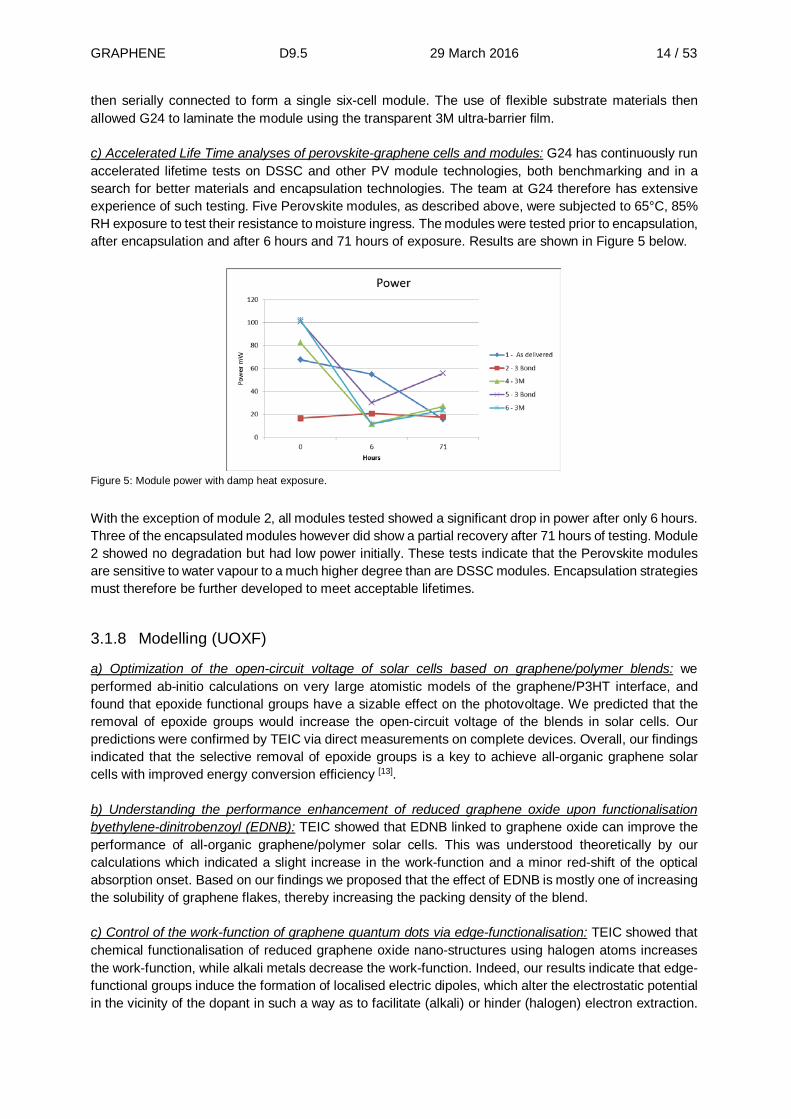
then serially connected to form a single six-cell module. The use of flexible substrate materials then allowed G24 to laminate the module using the transparent 3M ultra-barrier film. c) Accelerated Life Time analyses of perovskite-graphene cells and modules: G24 has continuously run accelerated lifetime tests on DSSC and other PV module technologies, both benchmarking and in a search for better materials and encapsulation technologies. The team at G24 therefore has extensive experience of such testing. Five Perovskite modules, as described above, were subjected to 65°C, 85% RH exposure to test their resistance to moisture ingress. The modules were tested prior to encapsulation, after encapsulation and after 6 hours and 71 hours of exposure. Results are shown in Figure 5 below.
Figure 5: Module power with damp heat exposure.
With the exception of module 2, all modules tested showed a significant drop in power after only 6 hours. Three of the encapsulated modules however did show a partial recovery after 71 hours of testing. Module 2 showed no degradation but had low power initially. These tests indicate that the Perovskite modules are sensitive to water vapour to a much higher degree than are DSSC modules. Encapsulation strategies must therefore be further developed to meet acceptable lifetimes.
3.1.8 Modelling (UOXF)
a) Optimization of the open-circuit voltage of solar cells based on graphene/polymer blends: we performed ab-initio calculations on very large atomistic models of the graphene/P3HT interface, and found that epoxide functional groups have a sizable effect on the photovoltage. We predicted that the removal of epoxide groups would increase the open-circuit voltage of the blends in solar cells. Our predictions were confirmed by TEIC via direct measurements on complete devices. Overall, our findings indicated that the selective removal of epoxide groups is a key to achieve all-organic graphene solar cells with improved energy conversion efficiency [13]. b) Understanding the performance enhancement of reduced graphene oxide upon functionalisation byethylene-dinitrobenzoyl (EDNB): TEIC showed that EDNB linked to graphene oxide can improve the performance of all-organic graphene/polymer solar cells. This was understood theoretically by our calculations which indicated a slight increase in the work-function and a minor red-shift of the optical absorption onset. Based on our findings we proposed that the effect of EDNB is mostly one of increasing the solubility of graphene flakes, thereby increasing the packing density of the blend. c) Control of the work-function of graphene quantum dots via edge-functionalisation: TEIC showed that chemical functionalisation of reduced graphene oxide nano-structures using halogen atoms increases the work-function, while alkali metals decrease the work-function. Indeed, our results indicate that edge-functional groups induce the formation of localised electric dipoles, which alter the electrostatic potential in the vicinity of the dopant in such a way as to facilitate (alkali) or hinder (halogen) electron extraction.

GRAPHENE D9.5 29 March 2016 15 / 53
Based on these findings, we have developed a multiscale model of the work-function modification by edge-functionalization, and employed this model to study realistic graphene flakes that are not accessible by explicit quantum-mechanical calculations. We proposed to use aniline and nitrobenzene as edge-functional groups that could yield significant work-function tenability [14-15]. d) Atomic-scale investigation of the interface between graphene and organic-inorganic lead halide perovskites: We performed ab-initio calculations on the interface formed between pristine graphene and the prototype perovskite absorber, MAPbI3. Our work indicated that graphene induces a structural distortion on the first perovskite monolayer, which results into a local suppression of the octahedral tilt. This distortion is accompanied by a nanoscale ferroelectric polarization of 3 mC/m². We proposed that this novel interfacial ferro-electricity improves electron extraction from the perovskite and hinders electron-hole recombination. Our results are in line with experimental work showing increased charge extraction rates in perovskites solar cells when graphene blends are employed [16-18].
e) Computational design of novel perovskite absorbers with tunable optical band gaps: we proposed a Rb- based lead halide perovskite, which was subsequently synthesised [19]. We also explored the replacement of lead by other divalent metals using high-throughput computational screening and found 15 new hypothetical perovskites that have not yet been proposed or synthesized [20]. We extended these results to the case of heterovalent substitutions of Pb by a monovalent and a trivalent metal. This study led to the design of new double perovskites and to the filing of a patent [21]. f) High-accuracy calculations of the electronic and optical properties of monolayer transition-metal dichalcogenide absorbers: we investigated the electronic structure and the optical properties of bulk, bilayer and monolayer systems of the semiconducting MoS2, WS2, MoSe2, and WSe2. Our findings indicate that previous density-functional theory calculations overestimate the effective masses of these semiconducting TMCs. The character of the GW band gaps correctly reproduced the experimental trends: both bulk and bilayer systems show indirect band gaps, whereas the monolayers exhibit direct band gaps. The calculated band gaps are in good agreement with available experimental data. We also investigated the coupling between electrons and plasmons in these compounds, and the signature of electron-plasmon interactions in angle-resolved photoemission experiments [22].

GRAPHENE D9.5 29 March 2016 16 / 53
3.2 Battery applications (Task 9.2)
The objective is mainly dedicated to the preparation by various technological routes of battery electrodes using additives of graphene or GRM to improve the capacity of both cathodes and anodes used in Li+ batteries. Main routes studied so far include graphene as additive in high capacity cathodes (Li-rich layered oxide), as pure graphene electrode for flexible device or as additive in association with various Li+ hosting nano-structured material (Fe2O3, Sn, SnO2).
3.2.1 Graphene-based coating agent for Li+ batteries (CEA)
The goal of this study is to be able to prepare optimised carbon coatings on a Li-rich layered oxide (general formula: Li1+xM1-xO2, 0<x<1/3, M transition metal, mainly Mn, Ni, Co), referred to as “Li-rich” with good electrochemical performances in terms of rate capability. To this aim, Li-rich material is mixed with different graphene/graphene oxide solutions/suspensions provided either by WP9 partners (Graphenea, Avanzare and UCAM) or from other sources (Directa Plus). This mix is spray dried and heat treated under Ar/H2 atmosphere. Each sample of composite material produced with this method is characterised by electrochemical tests using coin cells. Graphene and reduced Graphene Oxides: From Raman spectra, it is observed that they are all multilayer graphenes. The graphene form UCAM seems to be the thinnest as the ratio G/2D is the highest. The Directa Plus displays the signature of graphite. This is because the flakes of “graphene” are very thick and present many layers of graphene. Graphenea and Avanzare materials display the typical signature of a disordered reduced graphene oxide. One can note that besides Directa Plus grade, all the others G and rGO grade present surfactant to stabilise the suspension. Directa plus sample: It is observed by SEM that the coating is rather homogenous but not present on every particle. The electrochemical results do not show significant improvement (Figure 6a). Graphenea and Avanzare samples: The drying was not possible due to the amount of surfactant present in the suspension. UCAM sample: A very little amount of material from UCAM was successfully dried. From SEM we observe that the particles present homogenous coating but that some bare particles are still present (less bare particles than in Directa Plus sample). However, electrochemical tests showed no capacity. This is probably due to the isolating behaviour of the coating. A heat treatment would have been necessary but not enough samples were recovered. Graphene oxides: A graphene oxide from Graphenea was tested using spray dryer. As graphene oxide is insulating, the effect of heat treatment on electrochemical performances has been investigated. Hence, heat treatments at 350°C and 450°C have been tested. Electrochemical results are displayed on (Figure 6b). It is clearly observed that an improvement of the capacity retention occurs at high C-rate for coated materials. Indeed, the sample treated at 450°C present a nice improvement of 20% of the capacity retention at 5C.

GRAPHENE D9.5 29 March 2016 17 / 53
a) b)
Figure 6: a) electrochemical behaviour of Directa Plus coated material. b) electrochemical behaviour of Graphenea graphene oxide
coated material heat treated at different temperatures.
3.2.2 Graphene-based Li-O2 batteries (UCAM)
The rechargeable aprotic lithium-air (Li-O2) battery is a promising technology for next generation energy storage, but its practical realization still faces many challenges. In contrast to standard Li-O2 cells, which cycle via the formation of Li2O2, we used a RGO electrode, the additive LiI, and the solvent dimethoxyethane (DME) to reversibly form and remove crystalline LiOH with particle sizes larger than 15 micrometres during discharge and charge. Hierarchically macroporous RGO electrodes (binder-free) are used because they are light, conductive, and have a large pore volume. High specific capacities, excellent energy efficiency (93.2%) with a voltage gap of only 0.2 volt, and impressive rechargeability were obtained. The cells tolerate high concentrations of water, water being the dominant proton source for the LiOH; together with LiI, it has a decisive impact on the chemical nature of the discharge product and on battery performance. Figure 7 shows the electrochemical performance of the Li-O2 battery. When limiting the specific capacity to 1000, 5000, and 8000 mA.h/gc, the cells show no capacity fade, with little increase in voltage polarization after 2000, 300, and 100 cycles, respectively (Figure 7a-c). Higher capacities >20000 mA.h/gc have also been demonstrated. When cycled at 1 A/gc (Figure 7c), the voltage gap is only ~0.2 V; at higher rates, the gaps widen (Figure 7d), increasing to 0.7 V at 8 A/gc. By using an RGO electrode and the redox mediator LiI, in a DME-based electrolyte, we demonstrated a highly efficient, rechargeable Li-O2 battery with extremely large capacities. Its operation involves the reversible formation and removal of LiOH crystals. The combination of electrolyte additives, the porous electrode structure, and the electrolyte solvent, synergistically, not only determines the chemical nature of the discharge product but also governs the physical size and morphology of it, playing a decisive factor in the capacity and rechargeability of the resulting Li-O2 battery. The cell capacity is typically within 25000 to 40000 mA.h/gc (i.e., 2.5 to 4.0 mA.h) range for an RGO electrode of 0.1 mg and 200 mm thick. After discharge, the weight of an electrode removed from the stainless steel mesh was~1.5 mg (2.7 V, 3.2 mA.h), giving a specific energy of 5760 W.h/kg, which is more than 50 times greater than that of the classical graphite-based Li-ion battery.

GRAPHENE D9.5 29 March 2016 18 / 53
Figure 7: Discharge/charge curves for Li-O2 batteries using RGO electrodes and a 0.05 M LiI/0.25 M LiTFSI/DME electrolyte with
capacity limits of 1000 mA.h/gc (a), 5000 mA.h/gc (b), and 8000 mA.h/gc (c), as a function of rate (d); three cycles were performed
for each rate in (d). The cell cycle rate is based on the mass of RGO; i.e., 5 A/gc is equivalent to 0.1 mA/cm².
3.2.3 Graphene electrodes for mobile applications (NOKIA)
We received samples from ALA Alliance Japan in addition to the samples from IIT and CIC within WP9 work package for the benchmarking. Results on samples from IIT and CIC were included in previous deliverable reports. Various samples from ALA Alliance Japan were tested including a) graphene plate; b) graphene paper; c) graphene cloth. Standard CR2032 coin cell was made using Li foil as counter electrode, Celgard separator and commercial available electrolyte, 1.0 M LiPF6 in ethylene carbonate and dimethyl carbonate, EC/DMC=50/50 (v/v), battery grade (Aldrich) as standard benchmark cell. The cell was first discharged at 0.1 mA for 10 cycles, and then 1 mA for 10 cycles, 10 mA for 10 cycles and back to 0.1 mA for 10 cycles. a) Graphene plate: The battery made from graphene plate shows high energy capacity in the first discharge but it degrades very quickly in the forthcoming discharge –charge cycles. The highest energy capacity is only 8.5 mAh/g. The highest energy density is 7.7 mWh/g and power density is 5.8 mW/g. The graphene plate has very smooth surface and this limits its energy capacity as well as energy density. b) Graphene paper: The battery made from graphene paper shows more reproducible discharge–charge cycles. The highest energy capacity is 80 mAh/g, the highest energy density is 34 mWh/g and power density is 82 mW/g. The graphene paper has rough surface and this improves its energy capacity as well as energy density. The power density from graphene paper battery is also high. c) Graphene cloth: The last sample is graphene cloth, where graphene was grown on the porous carbon fiber cloth. It has the highest energy capacity of 150 mAh/g and highest energy density of 87.5 mWh/g. However, the power density is mediocrely 3.25 mW/g. This may be due to the porosity of the electrode. The porous surface area can host many lithium ions that boost its energy capacity and energy density. However, if it is too porous, lithium ions may be trapped inside and the mobility is limited. This will reduce its power density. Engineering the surface and structure of the graphene electrodes is vital to tailor the energy and power density of lithium ion batteries. Even though lithium cations cannot go through rigid graphene layer, it will

GRAPHENE D9.5 29 March 2016 19 / 53
build up double layer capacitors within the lithium ion batteries as we reported before [23]. This means providing suitable porosity for lithium ions passing through, it may be possible to enable a lithium battery with both high energy and power density.
Figure 8: Cyclic voltammetry for batteries made from a) graphene plate, b) graphene paper and c) graphene cloth. Scanning speed:
1mV/s.
Figure 8 shows the slow scan-rate (1mV/s) cyclic voltammetry for a) graphene plate, b) graphene paper and c) graphene cloth. It shows the current density, and lithium ion intercalation curve are similar between graphene plate and graphene paper. However, for the porous graphene cloth, there are two peaks at cathodic direction. More lithium ions are intercalated into the graphene cloth and the current density also doubles (0.05 A/g vs. 0.02-0.03 A/g).
3.2.4 Graphene/Si nanoparticles Li+ batteries (UCAM)
UCAM used reduced graphene oxide (RGO) as a conductive network and substrate on which Si nanoparticles are formed via hydrothermal reaction. RGO-Si shows a reversible capacity of ~1500 mAh/g for the 2nd and 3rd cycles (Figure 9a) compared to Si without graphene which shows a significant irreversibility in the 3rd cycle. After 30 cycles, RGO-Si maintains a specific capacity of ~1000 mAh/g after 30 cycles, whereas the capacity of Si sharply dropped to <250 mAh/g, a performance worse than graphite despite a very high specific capacity >4000 mAh/g during the first cycle (Figure 9d). The high electrical conductivity of the graphene, the porous three-dimensional foam structure, and the ability of graphene surface to localize the Si nanoparticles and prevent aggregation are deemed contributing factors that enhanced the cycle stability of the RGO-Si electrode.

GRAPHENE D9.5 29 March 2016 20 / 53
Figure 9: (a) SEM images of RGO-Si. (b) Charge discharge curves of RGO-Si. (c) Charge discharge curves of Si. (d) Cycle stability
of Si and RGO-Si half-cells.
3.2.5 Graphene/Metal oxide composite (CIC)
Over the last two years research activity was focused on analysing the metals and metal oxide composites with rGO as binder-free self-standing flexible electrodes for lithium ion batteries. In this task different metals and metal oxides were tried over the past years. Among the various metals and metal oxides available, Sn, SnO2, and Si were chosen as metal and metal oxide components and rGO as matrix to support these metal and metal oxides in the composite electrode. This is due to the high specific capacity obtained from these metals either by alloying or by conversion reaction. Before forming the composite electrodes, optimization of the synthesis of self-standing porous matrix in the form of aerogels (more 3D structure) and films (more stacked graphene sheets) has been performed. Graphene acts as a supportive matrix to buffer the volume changes that happen in these metals and metal oxides. It also acts as a good conductive path for the charge to travel to the current collector. Water was used as a solvent for the synthesis of the composite electrode and no other organic solvent was used in the entire process of the synthesis of the electrodes. Sn and SnO2 self-standing composite electrodes show good electrochemical performance with a specific capacity of ~ 650 mAh/g at 50 mA/g and stable performances over 1000 cycles. Though these values are at par with the existing values in the literature, the challenge remains to get good coulombic efficiency values in the first and further cycles. A high loading is considered as an important parameter for the high volumetric and gravimetric energy densities. Thermal reduction of the GO/SnOx was performed at different temperatures and depending on the calcination temperature Sn or SnO2 has been obtained. Si-rGO self-standing binder free electrodes were also synthesized for the lithium ion batteries in the form of aerogels and films. Synthesis process has been optimized to obtain metallic silicon particles well distributed in the graphene matrix. However. a slight oxidation of the silicon on the surface of the metallic particles is evident from the surface analysis. A well homogeneously distributed silicon particles were observed in the free-standing films. It is important to mention here that the synthesis was carried out in the ethanol instead of the water, which oxidizes the metallic particles immediately due to the high reactivity of the silicon nanoparticles. The aim of the study was to achieve higher loading of the Si without any further agglomeration of the primary particles. Si content of 50 % by wt. has been observed. Self-standing electrodes were tested in
GRAPHENE D9.5 29 March 2016 21 / 53
the lithium ion battery using a CR2032 coin cell configuration. Lithium metal was used as reference/counter electrode and 1M LiPF6 in EC:DMC (1:1 by vol. %) has been used as electrolyte. Electrochemical performance of the self-standing electrodes shows a severe effect of the lower voltage cut-off on the different samples. It has been observed that the aerogels do not show any electrochemical activity from the silicon above 50 mV; however, the Si is observed to be active in the films above 75 mV. On the other hand high specific capacity values of ~ 750 – 800 mAh/g have been observed at 50 mA/g of charge/discharge rate. Such capacity values are observed to be highly stable over 100 cycles. One of the most important parameter for anodes in the lithium ion battery is the first cycle coulombic efficiency, which has been observed to be ~ 85 % in the case of Si-rGO composite electrodes and this gives a hope to make a full lithium ion cells based on high energy density cathode materials. Apart from the electrochemical techniques, materials were analysed with physico-chemical characterization techniques to check other physical properties of the materials. Over the past two years, research activity under the collaboration with Graphenea and NOKIA has also been carried out. Graphene samples from Graphenea have been tested in the form of the self-standing films for the lithium ion batteries and Sn/rGO composite electrodes were handed over to NOKIA to analyse the electrochemical performance and for benchmark purpose.
3.2.6 Graphene/Metal oxide composite (UCAM)
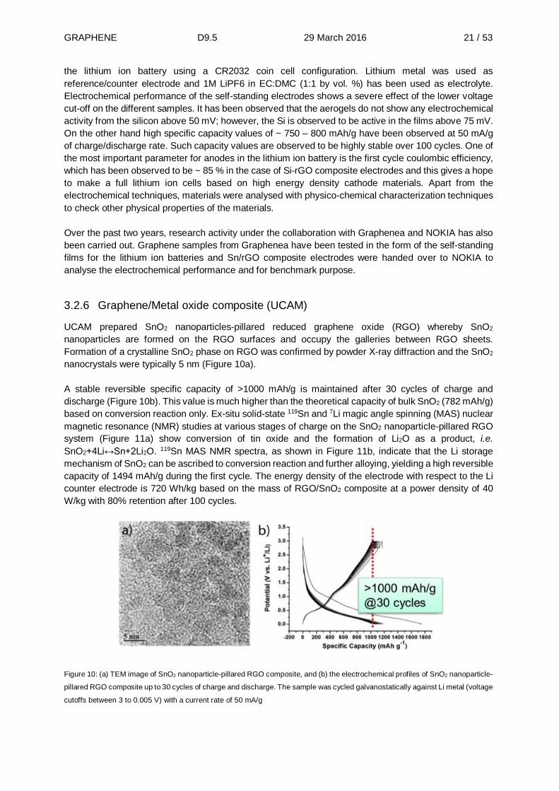
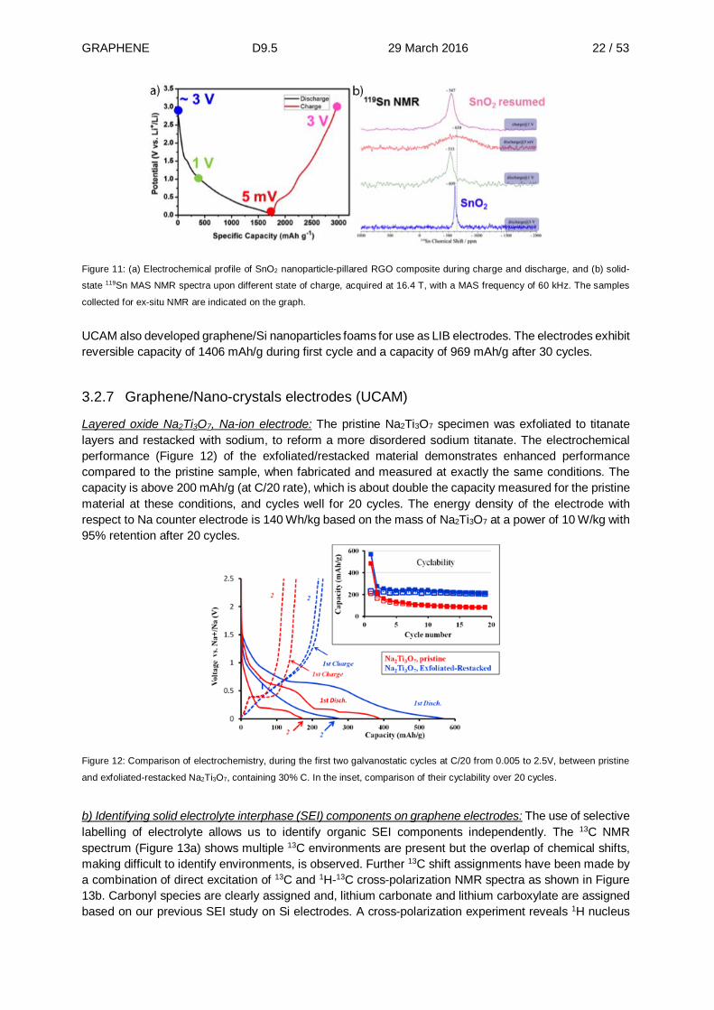
UCAM prepared SnO2 nanoparticles-pillared reduced graphene oxide (RGO) whereby SnO2 nanoparticles are formed on the RGO surfaces and occupy the galleries between RGO sheets. Formation of a crystalline SnO2 phase on RGO was confirmed by powder X-ray diffraction and the SnO2 nanocrystals were typically 5 nm (Figure 10a). A stable reversible specific capacity of >1000 mAh/g is maintained after 30 cycles of charge and discharge (Figure 10b). This value is much higher than the theoretical capacity of bulk SnO2 (782 mAh/g) based on conversion reaction only. Ex-situ solid-state 119Sn and 7Li magic angle spinning (MAS) nuclear magnetic resonance (NMR) studies at various stages of charge on the SnO2 nanoparticle-pillared RGO system (Figure 11a) show conversion of tin oxide and the formation of Li2O as a product, i.e. SnO2+4Li↔Sn+2Li2O. 119Sn MAS NMR spectra, as shown in Figure 11b, indicate that the Li storage mechanism of SnO2 can be ascribed to conversion reaction and further alloying, yielding a high reversible capacity of 1494 mAh/g during the first cycle. The energy density of the electrode with respect to the Li counter electrode is 720 Wh/kg based on the mass of RGO/SnO2 composite at a power density of 40 W/kg with 80% retention after 100 cycles.
Figure 10: (a) TEM image of SnO2 nanoparticle-pillared RGO composite, and (b) the electrochemical profiles of SnO2 nanoparticle-
pillared RGO composite up to 30 cycles of charge and discharge. The sample was cycled galvanostatically against Li metal (voltage
cutoffs between 3 to 0.005 V) with a current rate of 50 mA/g
GRAPHENE D9.5 29 March 2016 22 / 53
Figure 11: (a) Electrochemical profile of SnO2 nanoparticle-pillared RGO composite during charge and discharge, and (b) solid-
state 119Sn MAS NMR spectra upon different state of charge, acquired at 16.4 T, with a MAS frequency of 60 kHz. The samples
collected for ex-situ NMR are indicated on the graph.
UCAM also developed graphene/Si nanoparticles foams for use as LIB electrodes. The electrodes exhibit reversible capacity of 1406 mAh/g during first cycle and a capacity of 969 mAh/g after 30 cycles.
3.2.7 Graphene/Nano-crystals electrodes (UCAM)
Layered oxide Na2Ti3O7, Na-ion electrode: The pristine Na2Ti3O7 specimen was exfoliated to titanate layers and restacked with sodium, to reform a more disordered sodium titanate. The electrochemical performance (Figure 12) of the exfoliated/restacked material demonstrates enhanced performance compared to the pristine sample, when fabricated and measured at exactly the same conditions. The capacity is above 200 mAh/g (at C/20 rate), which is about double the capacity measured for the pristine material at these conditions, and cycles well for 20 cycles. The energy density of the electrode with respect to Na counter electrode is 140 Wh/kg based on the mass of Na2Ti3O7 at a power of 10 W/kg with 95% retention after 20 cycles.
Figure 12: Comparison of electrochemistry, during the first two galvanostatic cycles at C/20 from 0.005 to 2.5V, between pristine
and exfoliated-restacked Na2Ti3O7, containing 30% C. In the inset, comparison of their cyclability over 20 cycles.
b) Identifying solid electrolyte interphase (SEI) components on graphene electrodes: The use of selective labelling of electrolyte allows us to identify organic SEI components independently. The 13C NMR spectrum (Figure 13a) shows multiple 13C environments are present but the overlap of chemical shifts, making difficult to identify environments, is observed. Further 13C shift assignments have been made by a combination of direct excitation of 13C and 1H-13C cross-polarization NMR spectra as shown in Figure 13b. Carbonyl species are clearly assigned and, lithium carbonate and lithium carboxylate are assigned based on our previous SEI study on Si electrodes. A cross-polarization experiment reveals 1H nucleus

GRAPHENE D9.5 29 March 2016 23 / 53
is in close proximity to 13C. These results show experimental evidence of decomposition products and more characterisation of SEIs will be further provided by performing the same experiments with other labelled electrolyte and 2d NMR experiments.
Figure 13: 13C NMR spectra of RGO electrode cycled with 13C-enriched DMC electrolyte: (a) direct 1D 13C spectrum acquired at
11.7 T with a MAS rate of 30 kHz, and (b) 1H-13C CP spectrum. All peak assignments are shown on insets.
c) In situ NMR studies of graphene and graphene/nanocrystal electrodes: Measurement protocols were established in order to characterise graphene-related materials, such as RGO and RGO-SnO2 nanocomposite by in-situ ss-NMR to monitor and understand the fundamentals of their battery/supercapacitor charging mechanisms and detection of metastable chemical species during cycling. UCAM set an experimental baseline with graphite electrodes. In-situ 7Li NMR spectra (Figure 14) were acquired up to 70 hours and more than 7 cycles with Li metal peaks at 270 ppm and LiPF6 at -2.5 ppm and a peak corresponding to the intercalated Li is also noticeable at ~45 ppm. This method will be further applied to study Li (or Na) intercalation mechanism of graphene-based and layered materials and also detecting metastable metallic phases formed by alloying with charge carrier such as Li-Sn metallic phases.
Figure 14: In-situ 7LI NMR spectra up to 7th galvanostatic cycles with a rate of C/10. The peaks corresponding to Li metal and
LiPF6 electrolyte are indicated and continuous intercalation and de-intercalation of Li during cycling is demonstrated.
d) Investigating sodium storage in tin anodes for sodium-ion batteries – A combined pair distribution function analysis and solid-state NMR approach: The alloying mechanism of high-capacity tin anodes for sodium-ion batteries was investigated through the use of in-situ pair distribution function analysis (PDF), 23Na solid-state nuclear magnetic resonance (ss-NMR) and ex-situ 119Sn magic angle spinning ss-NMR.

GRAPHENE D9.5 29 March 2016 24 / 53
We have identified two previously unknown crystalline intermediates, and one amorphous intermediate. Upon initial sodiation, crystalline tin is converted into crystalline NaSn2. This is then broken down into a highly amorphous structure of approximate composition NaSn, which retains some of the tin-tin connectivity of the previous phases. Further sodiation results in the formation of Na2Sn, a phase consisting of sodium atoms between tin-tin dumbbells, and finally Na15Sn4. The NaSn2 structure is of particular interest as it consists of tin layers intercalated by sodium atoms. The tin atoms are arranged in a hexagonal honeycomb structure, reminiscent of stanene, a 2D material that has received considerable recent interest.
3.2.8 Battery Modelling and ageing test (REP)
During the period, we developed a P2D (pseudo two dimensions) simulator of charge/discharge at the cell scale. Concerning the calibration of the models by means of experimental tests, we conducted an experimental work to measure the degradation of the batteries with and without graphene. As anode we used metallic lithium and as cathode spinel plus Carbon Black or Graphene. The degradation tests were performed at 0.2C, 1C, 2C, 5C and 10C rates. Three different electrode formulations comprising an active lithium cathode composite and 15 wt% graphene (XG300), 15 wt% graphene (XG750) and 10 wt% graphene (XG300), were tested at a 0.2C rate (Figure 15a).
a) b) c)
Figure 15: a) evolution of cell voltage as a function of discharge capacity for 3 different electrode formulations, at 0.2C rate.
Evolution of cell voltage as a function of discharge capacity for an electrode with a formulation comprising a mix of graphene and
carbon black, compared at 0.2C (b) and 10C (c).
It can be thus concluded that the use of graphene as the only conductive additive does not allow the manufacturing of cathodes with satisfactory electrochemical performance. The results are different when a mix of graphene and Carbon Black is used instead. As can be seen in Figure 15a-b, when we pass from 0.2C to 10C the electrode developed is able to supply a capacity of 106 mAh/g during discharge. This result indicates that the electrode has a very good response to high currents and, in consequence, it is able to supply high power densities. In relation to the working voltage it is important to point out that it has high values, 4.0 V for 0.2C and 3.85V for 10C.
Figure 16 represents the cell voltage (V) vs. the areal capacity (mAh/cm²) registered at 30 mA/g (0.2C) rate, of four different electrode formulations comprising: (1) using spinel and 10 wt% carbon black (CB) (comparative); (2) LNMO and 5 wt% graphene (CC-GO1000) and 5 wt% CB; (3) LNMO and 5 wt% graphene (CC-GO2000) and 5 wt% CB; (4) LNMO and 5 wt% graphene (XG300) and 5 wt% CB. These curves also demonstrate the improved electrochemical performances of the electrode composites with graphene and carbon black compared to the electrode composites of the state of the art, due to their higher thicknesses, higher active material loading and consequently higher specific capacity and energy (mAh/g-total and Wh/kg-total) and higher areal capacity and energy (mAh/cm² and mWh/cm²).

GRAPHENE D9.5 29 March 2016 25 / 53
Figure 16: cell voltage as a function of the areal capacity for 4 different electrode formulations including graphene and carbon
black.
3.2.9 Full battery demonstrator integrating a pure graphene anode (IIT)
While not formally planned in the ramp-up phase of Graphene flagship, IIT developed a full lithium-ion
battery based on a graphene ink anode and a lithium iron phosphate cathode. A specific capacity of 165
mAhg−1, an estimated energy density of about 190 Wh kg−1 and a stable operation for over 80
charge−discharge cycles was demonstrated. This result is beyond the state of the art.
J. Hassoun et al, Nano Letters 2014, doi: 10.1021/nl502429m

GRAPHENE D9.5 29 March 2016 26 / 53
3.3 Supercapacitor applications (Task 9.2)
3.3.1 Graphene-based supercapacitors (CIC)
CIC energiGUNE has been working on fine-tuning the thermal reduction of graphite/graphene oxides to provide competitive materials for supercapacitors. Graphite oxide exfoliated by an in situ thermal-shock treatment (TEGO) was heat treated up to the temperature ranging between 600 °C and 1000 °C. The resultant materials (rGO600 etc) display micropore-free pore size distribution with specific surface area of 600-800 m2.g-1. In one example, this material was used to substitute for the positive microporous activated carbon electrode in a series hybrid capacitor based on hydroquinone (HQ)/benzoquinone (BQ) redox couple, which allows enhancing the energy output by increasing the cell capacitance. Mesoporous rGO electrode allowed increasing the rate response of the positive electrode, supposedly due to lower resistance and higher diffusion rate mesopores as compared with micropores in activated carbons. In another example, thermal reduction of graphene oxides was also conducted at temperatures between the exfoliation temperature and 1000 °C, varying parameters such as heating rate, materials loading, maximum temperature, etc… so as to increase capacitance and capacitance retention as well as to approach state-of-the-art materials in terms of energy density. Such low-temperature rGO provides much lower resistance and is able to withstand much higher current densities than microporous carbons at similar mass loading. Figure 17 provides an example of constant current charge/discharge curves in aqueous electrolytes, which shows that the resistive contribution is below 20-25 % of the total voltage drop for ultrahigh current densities of 100 to 200 A.g-1. This leads to a gravimetric power density of up to 75 kW/kg, which is well above 10-15 kW/kg achievable with typical microporous activated carbons.
Figure 17: Ultrafast electrochemical response achieved with low-temperature rGO. (a) Constant current charge/discharge profiles
of rGO-based aqueous supercapacitors for current densities of 100-200 A.g-1 in alkaline electrolyte; (b) the Ragone plot of rGO
based supercapacitors showing the gravimetric power density achievable with traditional ACs and with rGO. EDLC: Electric Double
Layer Capacitor.
An advantage of low-temperature rGO is that the developed synthetic methodology does not involve harsh synthesis conditions and can be potentially implemented into mass production. Apart from this work, supercapacitors using materials provided by partners Umeå University (WP 9) and Grupo Antolin and Graphenea (WP1) have been conducted. Activated TEGO sample from Umeå University was characterized in different organic electrolytes and will be further used as an electrode of hybrid organic-based supercapacitors. Chemically reduced graphene oxide from Graphenea and graphite oxide from Grupo Antolin were electrochemically characterized and improved to be suitable to supercapacitors through additional activation/post-treatment.
Limit of EDLC based on activated
carbons
Improvements achieved due to low-temperature
rGO
Alkaline aqueous

GRAPHENE D9.5 29 March 2016 27 / 53
3.3.2 Graphene-based supercapacitors (UCAM)
a) Nanocage-pillared RGO supercapacitors: CAM fabricated a new graphene-based supercapacitor, having the insertion of nanopillars as spacers in RGO (Figure 18a,b). The Ni-based M8L6 porphyrin-faced nanocage (M: metal, such as Ni(II), Fe(III)Cl and Zn(II), L: the tetrakis(pyridylimine)porphyrin ligand) was first tested as the spacer. Cycling the RGO/cage composite (consisting of 40 wt% cage) by cyclic voltammetry, in the range of 0-1.5 V with a sweep rate of 2 mV/s, showed electric double-layer formation (Figure 19a,b) and good prolonged cyclability over 1000 cycles. The gravimetric capacitance of the material was 100 F/g with respect to the mass of the RGO (Figure 19c), yielding an energy density of 16 Wh/kg. Decomposition of the cage spacer molecules limited the energy density by restricting the voltage to 1.5 V. Development of more electrochemically stable spacers are necessary for higher voltage. Also, the concentration of the spacers contribute a significant amount of inactive mass to the electrode, thereby decreasing the specific capacitance when the mass of the spacer is taken into consideration. A more suitable spacer will be electrochemically stable and also contribute to capacitance either through electric double layer capacitance or reversible redox reactions.
Figure 18: (a) Schematic of graphene layers with cage molecule in the interlayer. (b) Synthesis of cage molecules.
Figure 19: (a) Cyclic voltammetry of RGO-pillared spacers. (b) Charge discharge curves of RGO-pillared spacers. (c) Specific
capacitance vs mass ratio of rGO-pillared spacers. (d) Specific capacitance vs mass ratio of RGO-pillared spacers based on total
mass and on RGO mass.
b) Flexible graphene supercapacitors: UCAM synthesized a high viscosity (600 mPa.s at 100 s-1 shear rate) water based conductive graphene ink for the fabrication of electrodes for use in capacitive deionization devices. The ink has a total solids concentration of 10 % wt in water. The conductive part consists of graphene nanoplatelets (GNPs) and single/few layer graphene produced together by

GRAPHENE D9.5 29 March 2016 28 / 53
microfluidisation in aqueous sodium deoxycholate solutions. The GNPs have a mean thickness of 12 nm and a mean lateral size of 1 μm. Following microfluidisation sodium carboxymethylcellulose (CMC) is added as a binder and as rheology modifier adjusting the viscosity in the range of hundreds of mPa.s (600 mPa.s at 100 s-1 to 160 mPa.s at 1000 s-1 - thixotropic behaviour) thus making the ink easy to coat or print. UCAM produced coatings by blade coating and screen printing with a sheet resistance of 5 Ω/sq at 25 µm film thickness (dried at 100 °C for 10 min) which is suitable for electrodes in capacitor devices. In Figure 20a, we measured a capacitance of 30 F/g, which also shows a CV with a rectangular shape, indicating the electric double layer adsorption of ions. Figure 20b,c show the charge (electroadsorption) and discharge (electrodesorption) over 10000 cycles, a clear evidence of high cyclability of the electrode due to high Coulombic efficiency (and thus energy efficiency) between charge and discharge processes. (Figure 20d).
Figure 20: a. Cyclic voltammeter of graphene-CMC electrode. b. Charge-discharge cycles of graphene-CMC electrode. c. Cycle
stability. d. Coulombic efficiency.
c) In-situ NMR studies of supercapacitors: UCAM used in-situ NMR to directly quantify the populations of anionic and cationic species within a working microporous carbon supercapacitor electrode. Our results show that charge storage mechanisms are different for positively and negatively polarized electrodes for the electrolyte tetraethylphosphonium tetrafluoroborate in acetonitrile; for positive polarization charging proceeds by exchange of the cations for anions, whereas for negative polarization, cation adsorption dominates. Observation of ring current effects and their pronounced effects on NMR shifts confirm that activated carbons have complex structures consisting of curved graphene sheets. These results provide new molecular-level insight, with the methodology offering exciting possibilities for the study of pore/ion size, desolvation and other effects on charge storage in supercapacitors.
3.3.3 Graphene-based supercapacitors testing (REP)
Electrodes were processed using the same chemical method and in all the cases the composition was the same: 90 wt% carbon material + 10 wt% PVDF (Polyvinilidene fluoride). Both aqueous and organic electrolytes were used. Also the density of specimens was determined with the objective to reference capacities, energies and power both by mass and by volume of electrode.
GRAPHENE D9.5 29 March 2016 29 / 53
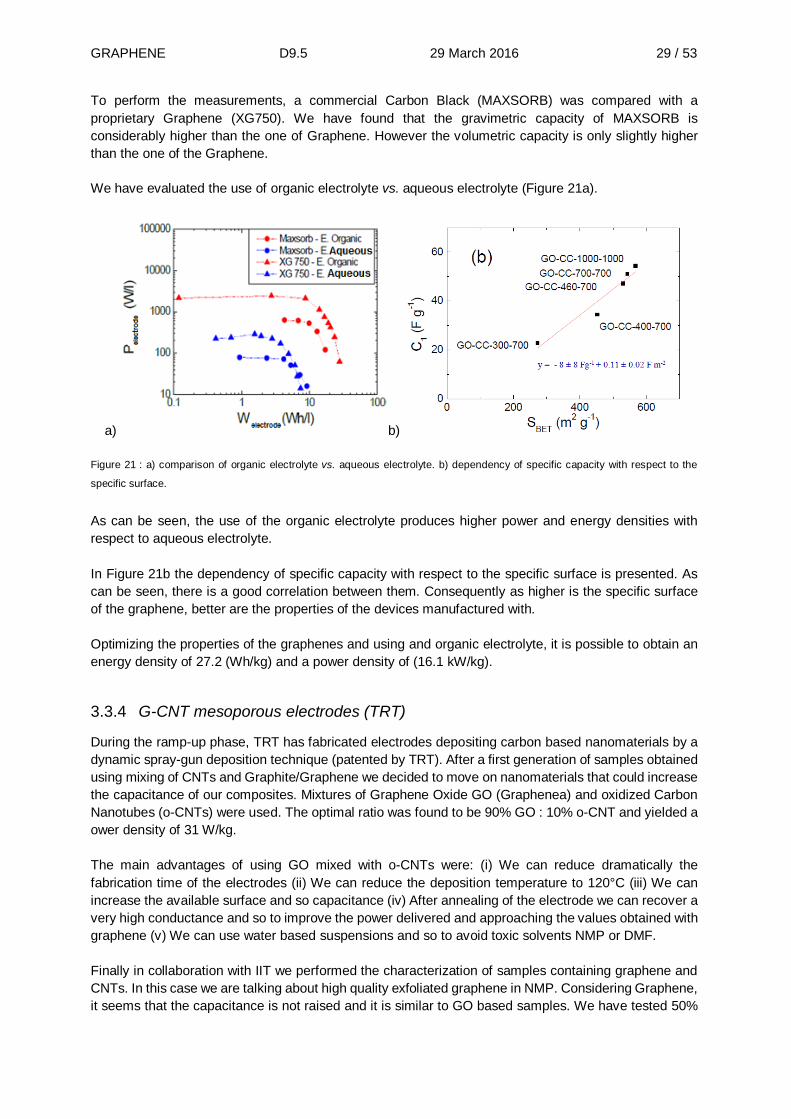
To perform the measurements, a commercial Carbon Black (MAXSORB) was compared with a proprietary Graphene (XG750). We have found that the gravimetric capacity of MAXSORB is considerably higher than the one of Graphene. However the volumetric capacity is only slightly higher than the one of the Graphene. We have evaluated the use of organic electrolyte vs. aqueous electrolyte (Figure 21a).
a) b)
Figure 21 : a) comparison of organic electrolyte vs. aqueous electrolyte. b) dependency of specific capacity with respect to the
specific surface.
As can be seen, the use of the organic electrolyte produces higher power and energy densities with respect to aqueous electrolyte. In Figure 21b the dependency of specific capacity with respect to the specific surface is presented. As can be seen, there is a good correlation between them. Consequently as higher is the specific surface of the graphene, better are the properties of the devices manufactured with. Optimizing the properties of the graphenes and using and organic electrolyte, it is possible to obtain an energy density of 27.2 (Wh/kg) and a power density of (16.1 kW/kg).
3.3.4 G-CNT mesoporous electrodes (TRT)
During the ramp-up phase, TRT has fabricated electrodes depositing carbon based nanomaterials by a dynamic spray-gun deposition technique (patented by TRT). After a first generation of samples obtained using mixing of CNTs and Graphite/Graphene we decided to move on nanomaterials that could increase the capacitance of our composites. Mixtures of Graphene Oxide GO (Graphenea) and oxidized Carbon Nanotubes (o-CNTs) were used. The optimal ratio was found to be 90% GO : 10% o-CNT and yielded a ower density of 31 W/kg. The main advantages of using GO mixed with o-CNTs were: (i) We can reduce dramatically the fabrication time of the electrodes (ii) We can reduce the deposition temperature to 120°C (iii) We can increase the available surface and so capacitance (iv) After annealing of the electrode we can recover a very high conductance and so to improve the power delivered and approaching the values obtained with graphene (v) We can use water based suspensions and so to avoid toxic solvents NMP or DMF. Finally in collaboration with IIT we performed the characterization of samples containing graphene and CNTs. In this case we are talking about high quality exfoliated graphene in NMP. Considering Graphene, it seems that the capacitance is not raised and it is similar to GO based samples. We have tested 50%

GRAPHENE D9.5 29 March 2016 30 / 53
type examples that shows an increase of a factor 5 concerning the power delivered of Graphite/Single Wall CNTs based electrodes with the same weight (92 kW/kg compared to 18 kW/kg) as it is pointed out in Figure 22a. The mixture of graphene and CNTs allows obtaining the best results from the point of view of the power performances and this can be easily explained considering that the conductivity of the high quality graphene layers are really the best ones tested. However, we have to take into accounts that in case of using GO we can exploit a green-type process based on water and in case of graphene we have to use NMP which is quite toxic and with a higher boiling point compared to water. The price of graphene suspensions is also higher than GO based suspensions. Their utilisation will depend on the application targeted. In the last six months, we moved to the fabrication of large surface aluminum based (substrate) supercapacitors. Indeed in order to implement the fabrication of supercapacitors we need to implement their fabrication in roll-to-roll fabrication pilot lines. In this case, we need to use aluminum as substrate. We have developed the process using GO and o-CNTs in water but also solvent that allow to reduce the oxidation of the surface during the deposition as the DichloroEthane. Thanks to this work, now we are able to fabricate large surface supercapacitors on industrial substrate.
a) b)
Figure 22 : Comparison between the performances of graphene/CNTs (high quality exfoliated graphene) based samples and
previous graphite/graphene/CNTs based. Large surface electrode (10*10 cm2) fabricated on industrial aluminum based substrate.

GRAPHENE D9.5 29 March 2016 31 / 53
3.4 Fuel cell applications (Task 9.3)
3.4.1 Low Pt content fuel cells (SU)
a) Development of platinum deposited graphene based electrodes: Pt nanoparticles were successfully decorated on graphene nanoplatelets and GO supports as very well dispersed and very small particles 2-3 nm by ethylene glycol reflux and 1-2 nm by supercritical CO2 deposition. The same was achieved with PtX (X=Cu, Ni, Co) alloy nanoparticles on GO. These nanoparticles exhibited better electrocatalytic activity compared to Pt/GO and commercial Pt/Vulcan XC-72 based catalysts. b) Development of graphene-based nanocomposites as catalyst supports: In a first approach, after the synthesis of Pt/rGO and Pt/rGO/Vulcan XC-72 catalysts, nanocomposites based on Pt/rGO, poly(vinylidene fluoride-co-hexafluoropropylene) (PVDF-c-HFP) and Nafion® were electro-spun or electro-sprayed over carbon paper to form electrodes. Electro-sprayed electrodes exhibited higher power output and Pt utilization efficiency. In a second approach, GO/polypyrrole (PPy), Vulcan XC-72/PPy, and their hybrid nanocomposites were successfully prepared and have been used as catalyst support for Pt nanoparticles. An improved electrocatalytic activity of Pt loaded hybrid nanocomposite as compared to both Pt/rGO and Pt/PPy/Vulcan XC-72 was obtained. c) Development of functionalized graphenes as catalyst supports: We achieved the modifications of GO via covalent functionalization with novel functional reagents p-phenylenediamine (GO-NH2) and Gly-Arg-Gly-Asp-Ser-Pro (GO-RGD) and also N-doping (GO-N doped) to enhance anchoring and growth of Pt nanoparticles. For the functionalisation studies, GO acquired through Flagship from GRAnPH (GRUPO ANTOLIN-INGENIERA) was employed. Structural analysis of these functionalized GO evidenced the successful GO reactions with the corresponding chemical moieties. The improved electrocatalytic activities compared to Pt/Vulcan XC-72 and Pt/rGO were achieved for the functionalized GOs. Moreover, Pt/GO-RGD exhibited significantly better distribution of Pt nanoparticles and electrocatalytic activity compared to Pt/GO-NH2 and Pt/GO-N doped. d) Graphene-carbon black hybrids as catalyst support: A new approach was applied to prepare Pt/rGO/Vulcan XC-72 hybrid electrocatalysts. Unlike literature, first GO and carbon black in varying ratios were homogenously mixed and then Pt was impregnated onto the hybrid support by EG reflux. According to our approach carbon black was acted as a spacer for both Pt impregnation and electrode preparation steps. Thus GO/Vulcan XC-72 based hybrid Pt support can ease the diffusion while it is promoting the use of high electrical connectivity and surface area of graphene. The average diameter of the Pt nanoparticles is about 2 nm from TEM micrographs and no large aggregates were observed. The addition of carbon black to the 2D graphene support structure improved electrocatalytic activity for Pt nanoparticles dispersed on the support. e) Fuel cell integration and characterization: G based electrodes were fabricated by using G supported Pt nanoparticles as the catalyst layer and by air-spraying of catalyst ink to gas diffusion layer. The prepared G based electrodes were integrated into membrane electrode assembly (MEA) structure using commercial Nafion® membranes. The evaluation of resultant MEAs in fuel cell operating conditions was performed. As far as the PEM fuel cell performances of Pt/rGO, Pt/G and Pt/Vulcan XC-72 prepared by EG reflux were concerned, Pt/rGO exhibited substantially better fuel cell performance compared to Pt/G and Pt/Vulcan XC-72 (Fig. 23a). Fuel cell performances of G supported Pt catalysts (Pt/G) by scCO2 deposition were evaluated and maximum power density of 335 mW.cm-2 was achieved (Fig. 23b). For electrosprayed nanocomposites, the maximum power densities, 324 mW.cm-2 for Pt/rGO electro-sprayed electrode and 441 mW.cm-2 (50% higher than that of conventional air-sprayed Pt/Vulcan XC-72) for Pt/rGO/Vulcan XC-72 hybrid electro-sprayed electrode were achieved at relatively low catalyst loadings of 0.2 mg Pt.cm-2(Fig. 23c). The performances of the hybrid electrocatalysts with varying GO to Vulcan XC-72 ratios were investigated as well. We determined that Pt/rGO/Vulcan XC-72 (rGO:Vulcan

GRAPHENE D9.5 29 March 2016 32 / 53
XC-72, 75:25) possessed the best performance, the maximum power density of 645 mW.cm-2 and Pt utilization efficiency of 2.6 kW/g Pt (Fig. 23d).
Figure 23: Polarization curves of MEAs at 60°C, TEM images (insets), maximum power density and Pt utilization efficiency: (a)
Comparison of Pt/rGO, Pt/G and Pt/Vulcan XC-72 catalysts prepared by EG reflux (Pt loading: 0.25 mg Pt cm-2); (b) Comparison
of Pt/G catalysts at various Pt loadings prepared by scCO2 deposition (Pt loading: 0.3 mg Pt cm-2); (c) Comparison of electrodes
prepared via electrospraying and airspraying (Pt loading: 0.2 mg Pt cm-2); (d) Graphene-carbon black hybrids at varying ratios (Pt
loading: 0.25 mg Pt cm-2).
3.4.2 Low Pt content and Pt-free CN-based fuel cells: Grafus project (BRETON) BRETON has been working in close collaboration with UNIPD to achieve the following goals: (a) synthesize the best-performing electrocatalysts (ECs) of GRAFUS; and (b) fabricate and test MEAs. In particular, BRETON received the know-how to synthesize the highest performance “PGM-free” EC devised by UNIPD, labelled FeSn0.5-CNl 900/Gra (II). The protocol for the preparation of this EC was jointly patented by UNIPD and BRETON [24]. A further activity of BRETON was to set up and equip a dedicated laboratory to execute the research of GRAFUS. Two main lines of work were pursued: (i) assembly and testing of a plant able to produce ECs in 10 g batches; and (ii) implementation of the facilities necessary to fabricate and test MEAs with an active area of the order of 50-100 cm². To meet the targets of GRAFUS, the functional components (the anion-exchange membrane, the ionomer and the gas-diffusion layers) must have a uniform performance level, a design specifically tailored for operation in fuel cells and a high performance. Breton selected FuMA-Tech and AvCarb Material Solutions. The outcomes of these efforts are shown in 24.
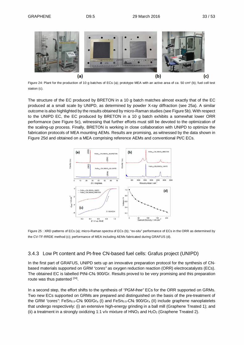
GRAPHENE D9.5 29 March 2016 33 / 53
Figure 24: Plant for the production of 10 g batches of ECs (a); prototype MEA with an active area of ca. 50 cm² (b); fuel cell test
station (c).
The structure of the EC produced by BRETON in a 10 g batch matches almost exactly that of the EC produced at a small scale by UNIPD, as determined by powder X-ray diffraction (see 25a). A similar outcome is also highlighted by the results obtained by micro-Raman studies (see Figure 5b). With respect to the UNIPD EC, the EC produced by BRETON in a 10 g batch exhibits a somewhat lower ORR performance (see Figure 5c), witnessing that further efforts must still be devoted to the optimization of the scaling-up process. Finally, BRETON is working in close collaboration with UNIPD to optimize the fabrication protocols of MEA mounting AEMs. Results are promising, as witnessed by the data shown in Figure 25d and obtained on a MEA comprising reference AEMs and conventional Pt/C ECs.
Figure 25 : XRD patterns of ECs (a); micro-Raman spectra of ECs (b); “ex-situ” performance of ECs in the ORR as determined by
the CV-TF-RRDE method (c); performance of MEA including AEMs fabricated during GRAFUS (d).
3.4.3 Low Pt content and Pt-free CN-based fuel cells: Grafus project (UNIPD)
In the first part of GRAFUS, UNIPD sets up an innovative preparation protocol for the synthesis of CN-based materials supported on GRM “cores” as oxygen reduction reaction (ORR) electrocatalysts (ECs). The obtained EC is labelled PtNi-CNI 900/Gr. Results proved to be very promising and this preparation route was thus patented [24]. In a second step, the effort shifts to the synthesis of “PGM-free” ECs for the ORR supported on GRMs. Two new ECs supported on GRMs are prepared and distinguished on the basis of the pre-treatment of the GRM “cores”: FeSn0.5-CNl 900/Gra (I) and FeSn0.5-CNl 900/Gra (II) include graphene nanoplatelets that undergo respectively: (i) an extensive high-energy grinding in a ball mill (Graphene Treated 1); and (ii) a treatment in a strongly oxidizing 1:1 v/v mixture of HNO3 and H2O2 (Graphene Treated 2).

GRAPHENE D9.5 29 March 2016 34 / 53
Figure 26 compares the results determined on the best ECs obtained during GRAFUS with the Key Performance Indicators (KPIs) proposed for the project. The onset potentials of the “PGM-free” FeSn0.5-CNl 900/Gra (I) and FeSn0.5-CNl 900/Gra (II) ECs in an alkaline medium are equal to 0.873 and 0.882 V vs. RHE (see Figure 236a); the onset potential of the Pt/C ref. in the same conditions is 0.946 V vs. RHE; the difference between these performance figures is between 60 and 80 mV, lower than the 100 mV KPI limit indicated for GRAFUS. The efficiency in the ORR is determined at a current density J50% equal to 3.5 mA·cm-2, i.e., 50% of the maximum value measured for the Pt/C ref at ca. 0.3 V vs. RHE. In these conditions, the efficiency in the ORR of FeSn0.5-CNl 900/Gra (I) and FeSn0.5-CNl 900/Gra (II) ECs in an alkaline medium is equal to 54.0% and 60.9% (see Figure 23b); these values are higher than the 50% KPI reported for GRAFUS. The durability of the ECs is gauged by an accelerated ageing protocol consisting in voltammetric cycling between 0.6 and 1.0 V vs. RHE [25].The evolution of the onset potential of the FeSn0.5-CNl 900/Gra (II) and of the Pt/C ref. is reported in Figure 236c. Results indicate that, within the 15000-cycle KPI indicated for GRAFUS, both ECs show practically the same degradation trend, which is compatible with the intended applications. On this basis, it was concluded that the target fixed in the project GRAFUS are satisfactorily reached. Furthermore, significant progress is also achieved in the fabrication of demonstrators of membrane-electrode assemblies (MEAs) including anion-exchange membranes (AEMs). Results obtained on reference systems assembled with FuMA-tech membranes and conventional Pt/C ECs are steadily improving (see Figure 236d).
Figure 23: Comparison between the Key Performance Indicators (KPIs) of GRAFUS and the obtained results: ORR onset potential
E(J5%) (a); and ORR efficiency of the ECs at J50% (b); durability of FeSn0.5-CNl 900/Gra (II) upon cycling (c) ; Progress in the
performance of MEAs including AEMs fabricated during GRAFUS (d).
3.4.4 Low Pt content and Pt-free CN-based fuel cells: Grafus project (UNIVARSAW)
Graphene nanostructures are explored as supports (carriers) for dispersed metallic silver nanocentres that exhibit electrocatalytic activity toward reduction of oxygen in alkaline media. To facilitate fabrication, immobilization and distribution of Ag(0) nanoparticles, various types of graphene (e.g. reduced graphene oxide, RGO, and CFx graphene with carbon black) have been modified with the silver analogue of polynuclear Prussian Blue, namely with ultra-thin silver(I) hexacyanoferrate(II,III) layers. Following the heat-treatment step at temperatures as high as 400-600°C, some thermal decomposition of the

GRAPHENE D9.5 29 March 2016 35 / 53
cyanometallate network occurs and, consequently, metallic silver sites are generated. Their formation and distribution are facilitated by the voltametric potential cycling in KOH electrolyte. The most promising electrocatalytic results with respect to the reduction of oxygen (the highest currents and the most positive electroreduction potentials) have been obtained when graphene nanostructures are combined or intermixed with Vulcan XC-72R nanoparticles. What is even more important that, due to the presence of the polynuclear cyanoferrate modifier or linker, the amounts of the undesirable hydrogen peroxide intermediate are significantly decreased. Gold nanoparticles are fabricated onto the graphene-type nanostructured supports, and the resulting catalytic materials are explored here for the electroreduction of oxygen in alkaline medium. To avoid passivation of the gold catalytic nanostructures, we have developed a special approach to fabricate gold nanoparticles which are modified, stabilised and linked with oxygen or hydroxyl groups on graphene via the Keggin-type polyoxometallate, phosphododecamolybdate, inorganic ligand. It is apparent from transmission electron microscopic examination of graphene surfaces that the deposited gold nanoparticles have sizes ranging typically from 30 to 40 nm. During diagnostic electrochemical experiments in alkaline medium, the polyoxometallate agents are dissolved whereas gold nanostructures remain and exhibit long-term stability. On the whole, the graphene-supported nanostructured gold has acted as powerful catalyst for the electroreduction of oxygen in alkaline (0.1 mol dm-3 KOH) medium. In this respect, the reduced graphene oxide acts as a promising support for catalytic Au nanoparticles. Comparison has also been made to the performance of noble-metal-(platinum)-based conventional electrocatalysts. This research has been performed in collaboration with the group from University of Padova (Prof. Vito Di Noto, Dr. Enrico Negro and their co-workers). The collaboration have concerned both performing parallel experiments (e.g. diagnostic electrochemical measurements using rotating ring disk voltammetry and gas diffusion electrode on the samples of Fe-Sn catalysts prepared in Padova) and exchange of materials (graphene samples, catalytic components). The results are consistent with fairly reasonable (in comparison to platinum as a model system) electrocatalytic activity toward electroreduction in alkaline medium. On the whole, it should be emphasized that proposed catalytic materials (both in Padova and in Warsaw) are also tolerant to the presence of alcohol (e.g. methanol) in the solution. This observation implies their potential utility in alkaline alcohol fuel cells where crossover of the organic fuel to the cathode compartment is a serious problem.
3.4.5 Carbon nitrides for fuel cell and battery applications: (UCL, Imperial, Amalyst)
Bulk samples of graphitic carbon nitride (gCN) based on poly(triazine imide) (PTI) sheets containing intercalated Li+ and Br- or Cl- ions were prepared by reacting dicyandiamide (DCDA) in molten salts (KCl-LiCl; KBr-LiBr eutectic mixtures). The pale yellow solids were placed in contact with a range of solvents and we demonstrated exfoliation to yield liquids containing single- to few-layer carbon nitride graphene (CNG) sheets. The liquids constitute a new family of semiconducting inks with visible light absorbing properties. Evaporation of the solvent allowed characterization of the nanoflakes that formed hexagons up to 100-200 nm in diameter with perfect crystalline order within the CxNy layers (see Figure ).

GRAPHENE D9.5 29 March 2016 36 / 53
(a) (b) (c)
Figure 27: Polytriazine imide (PTI:LiBr) crystalline materials and CNG nanoflakes. (a) SEM image of bulk crystalline materials
showing external hexagonal morphology. (b) Photographs of CNG nanoinks. Visible light image at left shows yellow colour of
semiconducting CNG nanosheets and image at right shows UV excited photoluminescence. (c) AFM image of a single crystalline
CNG nanoflake containing 2 atomic layers.
This result constitutes successful demonstration of deliverable 1) and part of 2). Studies of the mixing properties with C-nanoinks are under way and will be continued to complete goal 2). A patent describing the exfoliated CNG nanoinks and the crystalline nanoflakes derived from them has been filed (application 1602808.6; 17.2.16). An alternative exfoliation route was also established, using a convenient, one-pot framework charging method, to generate solutions of individualised, negatively-charged carbon nitride ions at high concentrations (0.35 mg/ml), also avoiding the damage caused by sonication or aggressive oxidation. The method was successfully applied to three kinds of graphitic carbon nitride (gCNs), including amorphous polyheptazine C3N4, crystallised polytriazine imide (PTI) both with and without Br- ion intercalation. As shown in Figure 248, the dissolved CNG nanosheets exhibited a 2D layer structure with a few nm thickness, and a high yield (34 wt%) at an optimum nominal CN:Na ratio. The characteristic IR spectrum of the nanosheets is similar to that of the bulk material. Thermogravimetric analysis (TGA) illustrates a slightly lowered decomposition temperature due to the ultrathin nature of nanosheets. Direct covalent functionalisation of the carbon nitride anions has been achieved providing a model for future reactions to add catalysts or improve solubility.
(a) (b) (c)
(d) (e)
Figure 24: (a) Photograph of framework-charging exfoliated CNG in aqueous solution. (b) high-magnification SEM, (c) TEM and
(d) FTIR and (e) thermogravimetric profile of PTI raw powders and exfoliated CNG nanosheets.

GRAPHENE D9.5 29 March 2016 37 / 53
These various CN-based inks were then processed to produce ‘papers’ and 3D networks of graphene oxide/carbon nitride nanoflakes as (rGO-PTI) hybrid nanostructures (Figure 259). Working together with industry partner Amalyst the materials were decorated with low loadings of platinum and tested as cathode and anode catalysts for PEM fuel cells. The cathode catalytic activity of Pt on the rGO-PTI hybrid is significantly improved in comparison to Pt on PTI or rGO.
Figure 259: Preparation, morphology and compositions of a freeze-dried 3D PTI-Br/GO monolith.
Similar behaviour is observed in fuel cell tests (Figure 30), and further optimisation is ongoing to improve the electrode formulation. The results were compared with Pt nanoparticles deposited on crystalline PTI:LiBr that also shows promising performance as the anode catalyst. In this case, the incorporation of rGO appears to lower the performance (Figure ). Our potential cycling durability test shows that the Pt/PTI assembly is more durable than commercial Pt/Vulcan. In parallel with the fuel cell electrode performance studies the gCN and CNG-derived nanomaterials were infiltrated with conductive carbon nanoinks to improve their electronic conductivity. These materials were first tested for their performance as potential Li-ion battery anodes based on a theoretically predicted high capacity for Li+ storage. However, the reversible capacity was low due to slow Li+ insertion kinetics. The gCN/carbon nanomaterial composites are now being tested as PEM fuel cell catalyst supports and they show initially promising results with performance as the anode catalyst matching that of commercial Pt/C electrodes. Rotating disk electrode tests show that the Oxygen reduction reaction activity (ORR) is comparable to that of commercial Pt/C, and one long term potential cycling test shows that the material is more durable.

GRAPHENE D9.5 29 March 2016 38 / 53
Figure 30: Performance of carbon nitride layered materials and nanoassemblies as fuel cell catalyst supports. (a) Oxygen reduction
reaction activity (ORR) of Pt/PTI, Pt/rGO and Pt/rGO-PTI in comparison to commercial Pt/C in 0.1 M HClO4. (b-c) Performance as
anode and cathode catalyst in H2/O2 PEM fuel cell at 80°C. (d) Change in electrochemical surface area during long term potential
cycling (1.0 – 1.5 V) in 0.1 M HClO4.

GRAPHENE D9.5 29 March 2016 39 / 53
3.5 Hydrogen storage applications (Task 9.4)
3.5.1 Physisorption (UMEA)
Result 1. Hydrogen sorption by graphene: We established reliable routines for H2 sorption measurements using gravimetric system and volumetric system.) For this, we evaluated hydrogen storage properties of graphene powder samples prepared by exfoliation of various precursor graphite oxides. Precise correlation of H2 uptake with SSA values was found for all studied samples at 293K and 77K (120 bar H2 pressure). Therefore, physisorption of hydrogen by graphene is similar to other high surface area carbons (e.g. activated carbons and mesoporous carbon). Result 2. Hydrogen storage in “graphene scaffolds” with SSA up to 3400 m²/g: TUD showed that SSA of graphene of 3000-5000 m²/g were theoretically possible. Using optimization of KOH activation procedure of r-GO, we synthesized activated r-GO samples (a-r-GO) with surface area up to 2800-3400 m²/g and showed that its structure can be considered as “scaffolds”. Extra-high surface area and pore volume (up to 2.2 cm3/g) of a-r-GO are among the highest for carbon materials which is reflected in high hydrogen uptakes evaluated experimentally in a broad temperature interval (77-296K). Maximal excess H2 uptake of 7.5 wt% was obtained at 77K for sample of a-r-GO subjected to additional hydrogen annealing activation. Hydrogen activation procedure allows to increase H2 physisorption by ~10% thanks to the removal of residual oxygen and hydrogen saturation of defect (holes) edges. Results 3: H2 physisorption capacity of ~4 wt% found at solid CO2 temperatures 193K (120 bar H2), achieved using common industrial refrigeration methods. Temperature dependence of H2 physisorption was evaluated for several samples of graphene scaffolds with ultra-high surface area. Results 4: Metal nanoparticle (Pt, Pd) decoration of r-GO do not result in increase of H2 sorption, in contrast to some literature reports. None of studied samples exhibited physisorption above standard for nano-carbons trends. Results 5. Pilllared Graphene Oxides (pGO): Samples of pGO based on reaction of graphite oxide with benzene-1,4-diboronic acid (DBA) were synthesized (SSA in the range 50-1000 m²/g) and their H2 storage properties verified. Significantly nanoporous nature of samples was verified using nitrogen sorption experiments, in house and independently using collaboration with CISNanoGune partner. Hydrogen storage properties of pGO samples evaluated at 293K and 77K were found to be similar to other nanocarbons trends in relation to SSA values.
Progress towards targets.
Target storage values
2016: 2.5 wt% ambient temperature.
2018: 3.5 wt% ambient temperature
Current values:
1.2 wt% at ambient temperature (120 bar H2).
The hydrogen sorption at 300 bar is about twice
higher compared to 120 bar values (extrapolation).
~2.5 wt% at 250-300 bar H2
~4 wt% at 193K and 120 bar
7.5 wt% at 77K (saturated at 40-50 bar)
Figure 261: Summary diagram of targets (red) vs H2 storage parameters ()- 120 bar H2, ()- extrapolated to 300 bar measured.

GRAPHENE D9.5 29 March 2016 40 / 53
3.5.2 Decoration of Graphene and Graphene based materials processes (FBK)
FBK started a new session of wet chemical processes to optimize the decoration and the stabilization of Mg clusters on graphene flakes to improve the material cyclability. In parallel to graphene flakes, we utilized few-layers-graphene patches with the aim to infiltrate the Mg between layers. The few-layer-graphene here is utilized as a scaffold to limit the Mg cluster dimension and, at the same time, to reduce the cluster mobility at the temperatures required to absorb/desorb hydrogen. We still are trying to optimize the chemical process and looking for the better Grignard reactant. We are also considering the opportunity to pre-process the few-layer-graphene to allow a better Mg infiltration. In parallel, we are modelling the interaction between graphene and Mg clusters when placed on the graphene surface and between two graphene layers.
a) b) Figure 32: (a) Decoration of Mg in MWCNT. (b) Infiltration of Mg in nanostructures of Graphene. In Figure 2a, a Scanning electron Microscopy (SEM) of a Mg decoration in MWCNT is shown and in Figure 2b, a Transmission Electron Microscopy (TEM) of nanostructured Mg in Graphene flakes.
A preliminary Differential Pressure Apparatus instrument was realised. The instrument (Figure 273b) has had several upgrades to fully characterize graphene and graphene-based nanostructures with a wide range of measures: New container design for better control of the material temperature; Extended temperature range: from liquid nitrogen to 350ºC ; Extended pressure range: up to 100 bar ; Capability to characterize thermodynamics, kinetics and BET in one single instrument.
(a) (b)
Figure 273: (a) Reactor for production of Mg and G nanostructures in wet. (b) Inner layout of IDA instrument for the characterization
of gas sorption in solid state material.
In parallel, a reactor (Figure 273a) for upscaling the production of nanostructured Mg in Graphene through wet processes was designed and realized. The reactor can leverage the production from a hundred µg to ten grams in batch. It can work in pressurized environment (up to 30 bars of hydrogen) and in a wide range of temperatures (0 – 600°C).

GRAPHENE D9.5 29 March 2016 41 / 53
3.5.3 Hydrogen interaction with curved, nanostructured and functionalized graphene
(CNR-NANO)
a) Curvature and phonon driven intake, storage and release: Given the attitude of H2 to cumulate within concavities, we investigated whether this property could be exploited to drive the uptake/release in a graphene based storage system. We first considered “traveling concavities”, namely ZA phonons excited in counter-phase in alternating sheets, whose frequency is in the THz range for wavelengths in the nm scale. Simulation shows that these are able to transport H2 over macroscopic distances and therefore to pump, move, intake and release the gas through multilayers or nanoporous graphene. Pumping could be used to enhance GD for physisorption over the standard values at RT.
Once within the system, H2 can adhere stably by chemisorption on static convexities, due to enhanced reactivity, such as ripples, and subsequently be released from concavities by curvature inversion such as that created by traveling ZA phonons. GD for chemisorption is ~8%. These effects could be used in the different phases of a graphene-based storage device. As a side result, experimental and theoretical studies converge to a quantitative relationship between H coverage and band gap opening of graphene offering an operative way to measure the amount of chemisorbed H by STS measurements.
b) Hydrogen adsorption on Ti functionalized graphene: Ti adsorbed on graphene for metal mediated interaction tends to clusterize, forming large islands (~10nm). Although the adsorption and desorption kinetics was observed within a moderate range of temperatures (400-700 K) by thermal desorption spectroscopy, the active surface of Ti and therefore the GD is reduced by clustering. We demonstrated that it is possible to control the islands size and distribution by intentionally inducing defects in graphene by means of N2 sputtering onto the surface before exposure to Ti: defects pin the Ti atoms and prevent island coarsening. This results in the increase of active Ti surface by a factor of 4 to 5 leading to increase of GD to 1.8-2.4 wt% at room temperature, which is in good agreement with the key performance indicator. c) Graphene morphology manipulation: Because graphene morphology (curvature, defects) emerges as a key issue, we proceeded with specific studies in this direction. We found that graphene grown on SiC can display different (even opposite), but almost degenerate pattern of corrugation, which makes the system prone to curvature manipulation by means of external conditions, such as temperature changes or electric field. The latter effect might be enhanced by substitutional or structural defects, pointing to a flexo-electric effect, whose quantitative aspects are under evaluation. We therefore continued characterizing N-doped graphene prepared by N2 sputtering, by means of Scanning Tunneling Microscope. We aim to study the distribution of defects as a function of sputtering energy and other environmental conditions. Another system we considered interesting for the presence of defects is Quasi-free-standing monolayer graphene obtained by hydrogen intercalation of the buffer layer graphene on SiC. In this case defects induce complex electronic and transport properties on the graphene layer, which are investigated by STM and STS. Study of these defects and proposal for their exploitation to enhance graphene reactivity are currently under evaluation.
3.5.4 H2 storage modelling (TUD)
Computational studies of hydrogen adsorption in multilayered graphene systems with defect-induced porosity were performed using classical Grand canonical Monte Carlo simulations. We studied model systems with the porosity close to the one usually achieved in experiments (~1.1 cm3/g). We considered model systems which consist of infinite parallel graphene layers (separated by 7 Å) with ‘holes’ of different sizes (~6–30 Å). We found that the incorporation of defects (preferably small ‘holes’, up to 10 Å

GRAPHENE D9.5 29 March 2016 42 / 53
in diameter) results in the increase of theoretically possible surface areas beyond the limits of ideal defect-free graphene (~2700 m²/g) approaching ~5000 m²/g. This leads to promising hydrogen storage capacities of up to 6.5 wt% at 77K (15 bar). Shortly after our theoretical results, outstanding samples of “graphene scaffolds” with the pore volume of ~2.2 cm3/g and surface area ~3400 m²/g have been synthesized in the group of Dr. Talyzin. Hydrogen uptake of this material reaches 7.5 wt% (saturation value at 77K). This interesting experimental finding raises the question about the possible structure of this adsorbent. As a model that accounts for different orientations of graphene-like sheets, we propose a structure based on interlocked defective graphene layers (Figure 4). Hydrogen storage capacity of “interlocked” defective graphene sheets could reach ~7.5-8.0 wt% at 77K.
Figure 34: From a polycoronene layer (left) towards a 3D graphene scaffold: a set of interlocked layers (right).
In the last years much focus has been put on graphene-oxide (GO) frameworks (GOFs, alternatively called pillared graphene-oxide). However, the actual structure of GOFs based on covalent cross-linking of GO-layers has to be ruled out because of observed significant swelling of the materials (as proven by experimental studies in the group of Dr. Talyzin). The real structure can be most likely approximated by a stacking of graphene-oxide sheets intercalated with oligomers of benzene-1,4-diboronic acid. As a result, the structures are microporous (pore volume ~0.5 cm3/g) with surface areas close to 1000 m²/g and very small hydrogen uptake of ~2 wt % (77 K). Hydrogen storage by physisorption in graphene-based nanostructures is certainly comparable to the performance of state-of-art ‘reference’ materials such as metal–organic frameworks (MOFs) (their uptake normally does not exceed ~7 wt% at 77 K) and represents a practical solution for cryogenic H2 adsorptive storage. Furthermore, graphene-based materials are preferable compared to MOFs because the latter are (in many cases) humidity-sensitive (i.e., subject to hydrolysis) and very expensive to produce. The main problem in the experimental design of graphene-based adsorbents is a challenge to keep a well-defined interlayer separation in the prepared samples. A solution to this problem could be to look for more efficient ways of ‘pillaring’ defective graphene sheets, e.g. to consider composites made out of graphene (or graphene-oxide) and carbon nanotubes. Doping with Ca, Mg, Ti has been shown to be a plausible way to achieve interaction energies up to ~67 kJ/mol (to be compared with ~6-7 kJ/mol typical for H2 physisoprtion). Our results support the potential of metal-decorated AGNR-O to be used as a hydrogen storage medium at room temperature, similar to the performance of metal-hydride systems.
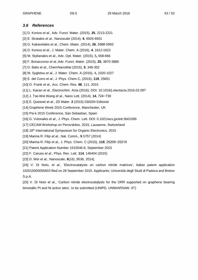
GRAPHENE D9.5 29 March 2016 43 / 53
3.6 References
[1] D. Konios et al., Adv. Funct. Mater. (2015), 25, 2213-2221
[2] E. Stratakis et al., Nanoscale (2014), 6, 6925-6931
[3] G. Kakavelakis et al., Chem. Mater. (2014), 26, 5988-5993
[4] D. Konios et al., J. Mater. Chem. A (2016), 4, 1612-1623
[5] M. Stylianakis et al., Adv. Opt. Mater. (2015), 5, 658-666
[6] F. Bonaccorso et al.,Adv. Funct. Mater. (2015), 25, 3870-3880
[7] D. Balis et al., ChemNanoMat (2015), 5, 346-352
[8] M. Sygletou et al., J. Mater. Chem. A (2016), 4, 1020-1027
[9] E. del Corro et al., J. Phys. Chem.C, (2015), 119, 25651
[10] O. Frank et al., Acc. Chem. Res. 48, 111, 2015
[11] L. Kavan et al., Electrochim. Acta (2016); DOI: 10.1016/j.electacta.2016.02.097
[12] J. Tse-Wei Wang et al., Nano Lett. (2014), 14, 724−730
[13] E. Quesnel et al., 2D Mater. 2 (2015) 030204 Editorial
[14] Graphene Week 2015 Conference, Manchester, UK
[15] Psi-k 2015 Conference, San Sebastian, Spain
[16] G. Volonakis et al., J. Phys. Chem. Lett. DOI: 0.1021/acs.jpclett.5b01099
[17] CECAM Workshop on Perovskites, 2015, Lausanne, Switzerland
[18] 18th International Symposium for Organic Electronics, 2015
[19] Marina R. Filip et al., Nat. Comm., 5 5757 (2014)
[20] Marina R. Filip et al., J. Phys. Chem. C (2015), 119, 25209−25219
[21] Patent Application Number 1515546.8, September 2015
[22] F. Caruso et al., Phys. Rev. Lett. 114, 146404 (2015)
[23] D. Wei et al., Nanoscale, 6(16) ,9536, 2014].
[24] V. Di Noto, et al., ‘Electrocatalysts on carbon nitride matrices’, Italian patent application
102015000055603 filed on 28 September 2015. Applicants: Università degli Studi di Padova and Breton
S.p.A.
[25] V. Di Noto et al., ‘Carbon nitride electrocatalysts for the ORR supported on graphene bearing
bimetallic Pt and Ni active sites’, to be submitted (UNIPD, UNIWARSAW, IIT)
GRAPHENE D9.5 29 March 2016 44 / 53
3.7 Dissemination activities (whole ramp-up phase period)
Title of papers Journal Authors / partners
General project overview
Graphene-based technologies for energy applications, challenges and perspectives
2D Mater. 2 (2015) 030204 Editorial
E. Quesnel et al. /CEA, TEIC, UNIPD , UMEA, TUD, FBK, UCAM, IIT, SU, CIC, UOX, TRT.
Photovoltaics Efficient charge transfer in solution-processed PbS quantum dot-reduced graphene oxide hybrid materials
J. Mater. Chem. C (2015), 3, 7088-7095
B. Martín-García et al. / IIT
A sustainable future for photonic colloidal nanocrystals
Chem. Soc. Rev. (2015), 44, 5897-5914
J.Q. Grim et al. / IIT
Graphene and transition metal dichalcogenide nanosheets as charge transport layers for solution processed solar cells
Submitted N. Balis et al. / TEIC
High efficient organic photovoltaic devices utilizing work-function tuned graphene oxide derivatives as the anode and cathode charge extraction layer
(2016) J. Mater. Chem. A, 4, 1612-1623
D. Konios et al. / TEIC
Functionalized Graphene as an Electron-Cascade Acceptor for Air-Processed Organic Ternary Solar Cells
(2015) Advanced Functional Materials, 25 (25), pp. 3870-3880.
F. Bonaccorso et al. / TEIC
Ternary organic solar cells with reduced graphene oxide-Sb2S3 hybrid nanosheets as the cascade material
(2015), ChemNanoMat, 5, 346-352 [Appeared in the back cover of ChemNanoMat]
N. Balis et al. / TEIC
Laser induced nucletion of plasmonic nanoparticles on two-dimensional nanosheets for organic photovoltaics
(2015), J. Mater. Chem. A, 4, 1020-1027
M. Sygletou et al. / TEIC
Stability enhancement of organic photovoltaic devices utilizing partially reduced graphene oxide as the hole transport layer: nanoscale insight into structural/interfaces properties and aging effects
(2015) RSC Advances, 5, 106930-106940
B. Paci et al. / TEIC
Photochemical Synthesis of Solution-Processable Graphene Derivatives with Tunable Bandgaps for Organic Solar Cells
(2015), Adv Opt Mater, 5, 658-666 [Appeared in the inside front cover] M.M. Stylianakis et al. / TEIC
Reduced graphene oxide micromesh electrodes for large area, flexible organic photovoltaic devices
(2015), Adv Funct Mater, 25, 15, 2213-2221 [Appeared in the inside front cover]
Konios D. et al. / TEIC
Improving the efficiency of organic photovoltaics by tuning the work-function of graphene oxide hole transporting layers
(2014), Nanoscale, 6, 6925-6931 E. Stratakis et al. / TEIC
Enhancement of the Efficiency and Stability of Organic Photovoltaic Devices via the Addition of a Lithium-Neutralized Graphene Oxide Electron-Transporting Layer
(2014), Chem Mater, 26 (20), 5988–5993
G. Kakavelakis et al. / TEIC
Raman Spectroscopy and in Situ Raman Spectroelectrochemistry of Isotopically Engineered Graphene Systems
Acc.Chem.Res. 48, 111-118 (2015) O. Frank et al. / JHIPC
Strain Assessment in Graphene Through the Raman 2D′ Mode
J.Phys.Chem. C 119, 25651-25656 (2015).
E. del Corro et al. / JHIPC
Low-temperature Fabrication of Highly-Efficient, Optically-Transparent (FTO-free) Graphene Cathode for Co-Mediated Dye-Sensitized Solar Cells with Acetonitrile-free Electrolyte Solution
Electrochim. Acta (2016) DOI: 10.1016/j.electacta.2016.02.097
L. Kavan et al. / JHIPC

GRAPHENE D9.5 29 March 2016 45 / 53
Novel Cathode and Photocathode Materials for Dye-Sensitized Solar Cells
66th Annual Meeting of ISE, Taipei, Taiwan, October 5, (2015) Proceedings, p. 826.
L. Kavan et al. / JHIPC
Advanced Nanocarbons (Graphene, Nanodiamond and Beyond) as the Electrode Materials in Dye-Sensitized Solar Cells
NanoPT 2016 International Conference, Braga, Portugal, February 16-19, (2016); Proceedings pp. 70-72.
L.Kavan
Stress and Charge Transfer in Uniaxially Strained CVD Graphene
IWEPNM 2016, Kirchberg, Austria, February 13-20, (2016), Book of Abstracts, pp. 44.
M. Bouša et al.
Quantification of uniaxial strain in monolayer graphene via the Raman 2D’ mode
IWEPNM 2016, Kirchberg, Austria, February 13-20, (2016), Book of Abstracts, pp. 59.
E. del Corro et al.
Enhanced electronic properties in mesoporous TiO2 via lithium doping for high-efficiency perovskite solar cells
(2016) Nature Communications, 7, art. no. 10379
F. Giordano et al. / EPFL
Highly efficient planar perovskite solar cells through band alignment engineering
(2015) Energy and Environmental Science, 8 (10), pp. 2928-2934
J.P. Correa Baena et al.
Efficient luminescent solar cells based on tailored mixed-cation perovskites
Science Advances, 01 Jan 2016 D. Bi et al.
Ferroelectric Graphene−Perovskite Interfaces (2015) Journal Physical Chemistry Letters DOI: 0.1021/acs.jpclett.5b01099
G. Volonakis et al. / UOXF
Electron-phonon interaction and pairing mechanism in superconducting Ca-intercalated bilayer graphene
Sci. Rep. 6, 21414 (2016) DOI: 10.1038/srep21414
E. R. Margine et al. /UOXF
Vibrational Properties of the Organic−Inorganic Halide Perovskite CH3NH3PbI3 from Theory and Experiment: Factor Group Analysis, First-Principles Calculations, and Low-Temperature Infrared Spectra
J. Phys. Chem. C, 2015, 119 (46), 25703–25718 DOI: 10.1021/acs.jpcc.5b07432
Miguel A. Pérez-Osorio, et al. / UOXF
GW Band Structures and Carrier Effective Masses of CH3NH3PbI3 and Hypothetical Perovskites of the Type APbI3: A = NH4, PH4, AsH4, and SbH4
J. Phys. Chem. C 2015, 119, 25209−25219 DOI: 10.1021/acs.jpcc.5b07891
Marina R. Filip et al. / UOXF
Energy-level alignment and open-circuit voltage at graphene/polymer interfaces: theory and experiment
2D Mater. 3, 015003 (2016) DOI: 10.1088/2053-1583/3/1/015003
Keian Noori et al. /UOXF
Computational Screening of Homovalent Lead Substitution in Organic−Inorganic Halide Perovskites
J. Phys. Chem. C 2016, 120, 166−173 DOI: 10.1021/acs.jpcc.5b11845
Marina R. Filip et al./ UOXF
GW quasiparticle band gap of the hybrid organic-inorganic perovskite CH3NH3PbI3: Effect of spin-orbit interaction, semicore electrons, and self-consistency
PHYSICAL REVIEW B 90, 245145 (2014)
Marina R. Filip et al./ UOXF
Steric engineering of metal-halide perovskites with tunable optical band gaps
NATURE COMMUNICATIONS 5 5757 (2014) DOI: 10.1038/ncomms6757
Marina R. Filip et al./ UOXF
Excitons in one-dimensional van der Waals materials: Sb2S3 nanoribbons
PHYSICAL REVIEW B 92, 125134 (2015)
F. Caruso et al. / UOXF
Spectral fingerprints of electron-plasmon coupling
PHYSICAL REVIEW B 92, 045123 (2015)
F. Caruso et al. / UOXF
Band Structures of Plasmonic Polarons PHYSICAL REVIEW LETTERS 114, 146404 (2015)
F. Caruso et al. / UOXF
Two-gap superconductivity in heavily n-doped graphene: ab initio Migdal-Eliashberg theory
PHYSICAL REVIEW B 90, 014518 (2014)
E. R. Margine et al. / UOXF
Efficiency and Stability Enhancement in Perovskite Solar Cells by Inserting Lithium-Neutralized Graphene Oxide as Electron Transporting Layer
Adv. Funct. Mater. 2016, DOI: 10.1002/adfm.201504949
Agresti A et al. / UTV, TEIC
Reduced Graphene Oxide as Efficient and Stable Hole Transporting Material in Mesoscopic Perovskite Solar Cells
Nano Energy 2016, DOI: 10.1016/j.nanoen.2016.02.027
Palma A. L et al. / UTV

GRAPHENE D9.5 29 March 2016 46 / 53
Graphene-based large area dye-sensitized solar cell module
Nanoscale 2016, DOI: 10.1039/C5NR07971C
Casaluci S et al. / UTV, IIT
Batteries and supercapacitors Electrochemically exfoliated graphene oxide/iron oxide composite foams for lithium storage, produced by simultaneous graphene reduction and Fe (OH) 3 condensation
Carbon 84, 254-262 Di Wei et al. / Nokia, CNR
Magnetic catalysts as nanoactuator achieve simultaneously momentum-transfer and continuous-flow hydrogen production
J. Mater. Chem. A, (2016), DOI: 10.1039/C5TA10697D
Di Wei et al. / Nokia
Sn- and SnO2-Graphene Flexible Foams Suitable as Binder-Free Anodes for Lithium Ion Batteries
J. Mater. Chem. A (2015), 3, 13402-132410
C. Botas / CIC
Cycling Li-O2 batteries via LiOH formation and decomposition
Science 2015, 350, 530-533 T. Liu et al. /UCAM
Fuel cells Graphene-reinforced poly(vinyl alcohol) electrospun fibers as building blocks for high performance nanocomposites
RSC Adv., 5, 85009-85018 (2015). S. Ghobadi et al. / SU
Development of graphene supported platinum nanoparticles for polymer electrolyte membrane fuel cells: Effect of support type and impregnation reduction methods
Int. J. Hydrogen Energy, 42, 3114-3127 (2016)
L. I. Şanlı et al. / SU
Comparison of two different catalyst preparation methods for graphene nanoplatelets supported platinum catalysts
Int. J. Hydrogen Energy. 2016 (in press)
E. Das et al. / SU
Graphene-carbon black hybrid platinum supports via electrospraying as the new generation of electrode materials for PEM fuel cell
Nanotechnology (submitted) L. I. Şanlı et al. / SU
Graphene-carbon black hybrid supports for platinum nanoparticles with enhanced fuel cell performance
Int. J. Hydrogen Energy. (submitted) L. I. Şanlı et al. / SU
Oxygen reduction and nanostructured silver generated over graphene-supported cyanometallate network
In preparation to submit to Functional Material Letters
B. Dembinska et al.
Development of graphene-supported gold nanoparticles as catalysts for electroreduction of oxygen in alkaline medium
In preparation to submit to Journal of Power Sources
S. Zoladek et al.
“Core-shell” Fe-carbon nitride based electrocatalysts for the oxygen reduction reaction in polymer electrolyte membrane fuel cells
To be submitted to “Electrochimica Acta”
V. Di Noto al. / UNIPD
“Core-shell” carbon nitride based electrocatalysts for the oxygen reduction reaction bearing bimetallic active sites including Sn and Fe
To be submitted to “Applied Catalysis B: Environmental”
V. Di Noto et al. / UNIPD
Bimetallic, Pt-free “core-shell” carbon nitride electrocatalysts for the oxygen reduction reaction in the alkaline medium based on Sn and Fe supported on graphene
To be submitted to “ChemSusChem” V. Di Noto et al. / UNIPD, UNIWARSAW, IIT
Graphene-supported Fe, Co, Ni carbon nitride electrocatalysts for the ORR
To be submitted to “Journal of Power Sources”
V. Di Noto al. / UNIPD, UNIWARSAW, IIT
Carbon nitride electrocatalysts for the ORR supported on graphene bearing bimetallic Pt and Ni active sites
To be submitted to “Electrochimica Acta”
V. Di Noto et al. / UNIPD, UNIWARSAW, IIT
H2 storage Hydrogen adsorption by perforated graphene
Int. J. Hydrogen Energy. 2015, 40(20) P.6594-6599
I. A. Baburin et al. / TUD, UMEA
Porous Graphene Oxide/Diboronic Acid Materials: Structure and Hydrogen Sorption
J. Phys. Chem. C, 119, 27179–27191, (2015)
G. Mercier et al
Hydrogen storage in bulk graphene-related materials
Micropor Mesopor Mat 2015, 210, 46-51, (2015)
A. Klechikov et al.

GRAPHENE D9.5 29 March 2016 47 / 53
Hydrogen storage in high surface area graphene scaffolds
Chem.Comm., 51, 15280-15283 (2015) A. Klechikov et al.
Graphene oxide hydration and solvation: in-situ neutron reflectivity study
Nanoscale, 6, 12151–12156, (2014). A. Vorobiev et al.
A simple approach for the fabrication high transparent reduced graphene oxide films on glass substrates by dropcasting method
Submitted to Colloids and Surfaces A, 2015
Nguyen Van Chuc et al. / FBK
Nanoscale frictional characteristics of few layers graphene over Ni grain and grain boundaries
Accepted in Nanoscale M. Tripathi et al. / FBK
Hydrogen transport within graphene multilayers by means of flexural phonons
2D Materials (2015) 2, 014009 V.D. Camiola et al. / CNRNANO
Graphene, related two-dimensional crystals, and hybrid systems for energy conversion and storage
Science (2015) 347, 1246501 F. Bonaccorso et al. / CNRNANO
Hydrogen storage in rippled graphene: perspectives from multi-scale simulations
Frontiers in Materials 2, 00003 (2015) V.D. Camiola al. / CNRNANO
Increasing the active surface of titanium islands on graphene by nitrogen sputtering
Applied Physics Letters 106, 083901 (2015)
T. Mashoff et al. / CNRNANO
Nano-Scale Corrugations in Graphene: a Density Functional Theory Study of Structure, Electronic Properties and Hydrogenation
The Journal of Physical Chemistry C 119 (14), 7900–7910 (2015)
A Rossi et al. / CNRNANO
Graphene-based technologies for energy applications, challenges and perspectives
2D Materials (2015) 2 (3), 030204 E Quesnel, et al. / CEA
Correlation between morphology and transport properties of quasi-free-standing monolayer graphene
Applied Physics Letters 105 (22), 221604 (2014)
Y Murata et al. / CNRNANO
Multistable rippling of graphene on SiC: A Density Functional Theory study ,
Under submission T Cavallucci et al. / CNRNANO
Revealing the multi-bonding state between hydrogen and graphene–supported Ti clusters
Under submission K Takahashi et al. / CNRNANO
Efficient n-type Doping in Epitaxial Graphene through Strong Lateral Orbital Hybridization of Ti Adsorbate
Under submission J-WChen et al. / CNRNANO
Hydrogen adsorption by perforated graphene Int. J. Hydrogen Energy. 2015, 40(20) P.6594-6599
I. A. Baburin et al. / TUD
From zeolite nets to sp3 carbon allotropes: a topology-based multiscale theoretical study
Phys. Chem. Chem. Phys. 2015, 17. P. 1332–1338.
I. A. Baburin et al. / TUD
Hydrogen storage in high surface area graphene scaffolds
ChemComm. 2015, 51. P. 15280–15283
A. Klechikov et al. / TUD, UMEA
Porous Graphene Oxide/Diboronic Acid Materials: Structure and Hydrogen Sorption
J. Phys. Chem. C. 2015. 119 (49). P. 27179–27191
G. Mercier et al. / TUD, UMEA
Revealing the hidden correlated electronic structure of strained graphene
Phys. Rev. B, 2015, 91, 205120
L. Craco et al. / TUD
Water Splitting on TiO2-Based Electrochemical Cells: A Small Cluster Study
J. Phys. Chem. C, 2016, 120 (1), P. 437–449
F. Rodríguez-Hernández et al. / TUD
A First-Principles Study of Metal-Decorated Graphene Nanoribbons for Hydrogen Storage
Z. Phys. Chem., accepted D. C. Tranca et al. / TUD
Title of talk Conference Authors / partners
General project overview
Graphene for energy applications: an update on running activities within the Graphene Flagship European project
13th International Conference on Nanosciences & Nanotechnologies (NN16), 5-8 July 2016, Thessaloniki, Greece INVITED
E. Quesnel /CEA,
Photovoltaics Integration of CVD Graphene as Transparent Front Electrode into conventional a-Si:H thin film solar cells
Poster, Graphene Week 2015, Manchester, UK
F. Roux et al. / CEA, UCAM
Graphene monolayer produced on Pt reusable Oral presentation & proceeding of L.Golanski et al. / CEA

GRAPHENE D9.5 29 March 2016 48 / 53
substrates for transparent conductive electrodes applications.
“Trends in Nanotechnology” International Conference (TNT2015), Toulouse, France.
Integration of graphene as transparent conductive electrode for a-Si:H solar cells
Abstract submitted to the 31st EU PVSEC conference, Munich, June 2016
F. Roux et al. /CEA
Synthesis of Colloidal Quantum Dot - Reduced Graphene Oxide Hybrid Inks for Opto-Electronic Applications
E-MRS Spring meeting, Lille (France), 10th-15th May 2015
B. Martín-García et al. / ITT
Organic Photovoltaics Engineering: Plasmonic Nanoparticles and Graphene based materials for enhanced performance and stability
9th International School on Hybrid and Organic Photovoltaics, Tuscany Italy, Sep 2015. INVITED
E. Kymakis /TEIC
Solution processable graphene derivatives and related 2D crystals for high efficient organic and perovskite solar cells
12th International Conference on Nanosciences & Nanotechnologies Thessaloniki, Jul 2015. INVITED
E. Kymakis /TEIC
Graphene-based materials for organic photovoltaic devices
E-MRS Spring Meeting, Lille, May 2015 INVITED
E. Kymakis /TEIC
Current progress in organic PV materials and devices
Industrial Technologies 2014, WS21, Athens, Greece, Apr 2014.
E. Kymakis /TEIC
Molecular Photovoltaics and Artificial Photosynthesis
IASSF, 8-13 November 2015, Seoul, Korea.
M. Graetzel / EPFL
Masoscopic Photosystems for the Generation of Electricity and Fuels from Sunlight
Warshel Symposium, 19-22 November 2015, USC Dornsife ,Los Angeles, USA.
M. Graetzel / EPFL
Emjoy beyond oil LightChEC Symposium 2015, 27 November, 2015, Universität Zurich, Zurich.
M. Graetzel / EPFL
Perovskite/Graphene interfaces International Symposium for Organic Electronics - ISFOE 2015, Thessaloniki, Greece
G. Volonakis et al. / UOXF
Maximum Open-Circuit Voltage of Ideal Graphene/P3HT Organic Photovoltaic Interfaces
HIOS, Symposium on hybrid inorganic-organic systems for opto-electronics, Berlin 2015
F. Giustino /UOXF
Ferroelectric graphene-perovskite interfaces CECAM Workshop 'Perovskite solar cells: the quest for a theoretical description', Lausanne 2015
F. Giustino /UOXF
Computational photovoltaics: New materials and new methods
Psi-k 2015, Donostia-San Sebastian, Spain
F. Giustino /UOXF
Atomistic modelling of solar energy materials AMPEA Workshop on ‘Simulation and Characterization for Energy Materials and Devices’, June 2015, University College London.
F. Giustino /UOXF
Rational design of hybrid organic-inorganic perovskites
European Materials Research Society Spring Meeting, May 2015, Lille, France
F. Giustino /UOXF
Computational modelling of MaPbI3 PSCO 2015 – First International conference on perovskite solar cells and optoelectronics
F. Giustino/ UOXF
POSTER: Perovskite solar cells based on P3HT doped with functionalized graphene nanoplatelets
Graphene week 2015-
22th-26th June, Manchester (UK)
S. Casaluci et al. / UTV, IIT
ORAL: Perovskite solar cells stabilized by carbon nanostructure-P3HT blends
IEEE nano 2015
27th-30th July, Rome (Italy)
S. Casaluci et al. / UTV, IIT
ORAL: Solution Processable reduced graphene oxide as hole transporting material in mesoscopic perovskite solar cell
E-MRS (spring meeting) 2015
11th-15th May, Lille (France)
A. L. Palma et al. / UTV, IIT
ORAL: Lithium-Neutralized Graphene Oxide in Perovskite Solar Cells: an effective way to improve the performance and the stability
Submitted to Graphene week 2016 -
13th-17th June, Warsaw (Poland)
A. Agresti et al. / UTV, TEIC
GRAPHENE D9.5 29 March 2016 49 / 53
POSTER: Sprayed graphene doped mesoporous TiO2 film as an electron transport layer for perovskite photovoltaic devices
Accepted to Graphene 2016 - 19th-
22th April, Genova(Italy)
B. Taheri et al. / UTV
ORAL: Graphene-based large area dye-sensitized solar cell module
Accepted to Graphene 2016 - 19th-
22th April, Genova(Italy)
S. Casaluci et al. / UTV, IIT
ORAL: High Efficient Graphene Based Large Area (100cm2) Perovskite Solar Module.
Submitted to Fotonica 2016 AEIT -
6th-8th June, Rome(Italy)
A. Agresti et al. / UTV
Batteries and supercapacitors Graphene energy materials Commercial Graphene Show, Invited
talk, Apr. 2015, Manchester, UK D. Wei/ Nokia
Graphene for energy solutions Invited keynote speaker and chaired the Graphene Industry Section at Trends in Nanotechnology (TNT 2015), Toulouse, France
D. Wei/ Nokia
Sn/SnO2@rGO self-standing anodes for Lithium ion batteries
GraphIn International Workshop. December 3rd 2015. Zaragoza (Spain)
G. Singh et al. / CIC
Graphene-enhanced Aqueous Hybrid Supercapacitors Based on Redox Active Electrolytes
ISSECAp 15, 4th International Simposium on Enhanced Electrochemical Capacitors, June 8-12th, 2015. Montpellier (France), Invited lecture
R. Mysyk / CIC
Enhancing the Rate Capability of Hybrid Supercapacitors Based on Redox Active Electrolytes through High-Surface Area Reduced Graphene Oxide
227th Electrochemical Society Meeting, May 24 28th, 2015. Chicago (USA)
S. Roldan et al. / CIC
Supercapacitors based on reduced graphene oxide
Graphene and Related Materials (XXX Trobades Científiques de la Mediterrània 2014) Oct 15th-17th 2014, Mahón (Spain). Poster.
C. Botas et al. /CIC
Power Improvement of Hybrid Supercapacitors Based on Redox-Active Electrolytes by Using an Easily Synthesizable Reduced Graphene Oxide. Silvia Roldán. Poster
AABC Europe 2015, January 26 - 29, 2015. Mainz (Germany). Poster
S. Roldán / CIC
Repsol´s activities in Graphene Industrial Technologies 2014. 9-11 April 2014. Invited Speker
A. Páez / REPSOL
Benchmarking the effects of substrates upon Graphene properties, stability and processability to identify the optimal substrate for each application
Graphene Supply, Application & Commercialization. Manchester. June 12th-13th 2014. Invited Speaker.
A. Páez / REPSOL
Nanomaterials for different applications New trend in 2D materials, Spinograph workshop, IMDEA, 25 February Madrid 2016 , Invited Talk
P.Bondavalli / TRT
Graphene based supercapacitors Graphene Study, Graphene Flagship school, Ecole de physique des Houches, 22 January, 2016 , Invited Talk
P.Bondavalli / TRT
Graphene Based Supercapacitors : Results and Improvements
Graphene 2D Live 2015, IDTechex, 18-19 November 2015 Santa Clara US, Invited Speaker
P.Bondavalli / TRT
Graphene Based Supercapacitors : Results and Improvements
Electric Vehicles 2015, IDTechex, 18-19 November 2015 Santa Clara US, ,Invited Speaker
P.Bondavalli / TRT
Graphene-based supercapacitors fabricated by an innovative dynamic air-brush deposition technique
Graphene Canada October 14-16, Montrel 2015, Invited Speaker
G. Pognon / TRT
Graphene based electrodes for high performances supercapacitors,
Euronanoforum, Riga 9-12 June 2015, Invited Speaker
P.Bondavalli / TRT
Graphene based electrodes for high performances supercapacitors
Graphene applications, Volanthen group international workshop, 21-22 Mai 2015 Berlin, Invited Speaker
P.Bondavalli / TRT

GRAPHENE D9.5 29 March 2016 50 / 53
Graphene based electrodes for high performances supercapacitors
Graphene 2D Live 2015, IDTechex, 28-29 Avril 2015 Berlin, Invited Speaker
P.Bondavalli / TRT
Electrodes based on graphitic nanomaterials for high performances supercapacitors
Graphene Show, Manchester 16-17 Avril 2015, Invited talk
P.Bondavalli / TRT
Graphene based electrodes for high performances supercapacitors
Graphene 2015, Bilbao 9-13 March 2015, Invited talk
P.Bondavalli / TRT
Supercapacitors based on mixtures of Graphite/Graphene/CNT
Graphene Connect (Graphene Flagship event), 2021 October 2014, Dresden, Invited Talk
P.Bondavalli / TRT
Supercapacitors based on mixtures of graphite/graphene and carbon nanotubes fabricated using dynamic spray-gun deposition technique : advantages of nanomaterials
Graphene supply, commercialization and applications, 12-13 June 2014 Manchester, London Business School, invited Speaker
P.Bondavalli / TRT
Supercapacitors based on mixtures of graphite/graphene and carbon nanotubes fabricated using dynamic spray-gun deposition technique : advantages of nanomaterials and of this highly versatile deposition technique,
IDTechex, 1-2 Avril 2014 Berlin, Invited Speaker
P.Bondavalli / TRT
Supercapacitors based on mixtures of Graphite/Carbon Nanotubes fabricated using dynamic spray-gun deposition technique
POWER Autonomous Communicating Objects, PACO conference Aix-En-Provence, 24-25 October 2013, Invited Speaker
P.Bondavalli / TRT
Fuel cells Graphene based gas diffusion electrodes for polymer electrolyte membrane fuel cells
Koc University, December 24, 2015, Istanbul, invited speaker
S.Alkan Gürsel / SU
Preparation of Graphene Nanoplatelet Supported Platinum Catalysts by Supercritical Carbon Dioxide Deposition
Int. Symposium on Materials for Energy Storage and Conversion METU(mESC-IS 2015), September 9-11, 2015, Ankara, poster presentation
E. Das et al. / SU
Fuel Cell Electrodes based on Graphene 27th National Chemistry Congress, August 22-27, 2015, Çanakkale, invited speaker
L. I. Şanlı et al. / SU
Syntheses of Pt/Graphene Nanoparticles and Their Use as Catalyst for PEM Fuel Cells
5th Physical Chemistry Congress, May 16-19 , 2015, Konya, oral presentation
L. I. Şanlı et al. / SU
Development of Pt/Graphene Catalysts for PEM Fuels
1st National Carbon Conference, March 12-13, 2015. Istanbul, oral presentation
L. I. Şanlı et al. / SU
Modification of Graphene Oxide as Catalyst Support for Fuel Cells
Imagine Nano, March 10-13, 2015, Bilbao, poster presentation
V. Sadhu et al. / SU
Low Pt Fuel Cells Graphene Flagship- Graphene Connect - Energy Applications, October19-20, 2014, Dresden, invited speaker
S.Alkan Gürsel / SU
Graphene Flagship Project Graphene and Related Technologies 2014 Workshop, October 13-14, 2014, Istanbul, invited speaker
S.Alkan Gürsel / SU
Preparation and Characterization of Poly(vinylidene fluoride)/Graphene Oxide Nanocomposite Electrospun Electrodes for PEM Fuel Cell
Gordon Research Conferences -Fuel Cells, August 4-9, 2014. Rhode Island, poster presentation
B. Yarar et al. / SU
Graphene Flagship Project Graphene & Related Materials Workshop & Summer School, July 9-12, 2014, İzmir, invited speaker
S.Alkan Gürsel / SU
Fabrication of Electrospun Catalyst Layers Utilizing Graphene as Catalyst Support in PEM Fuel Cells
Graphene & Related Materials Workshop & Summer School, July 9-12, 2014, İzmir, poster presentation
V. Bayram et al. / SU

GRAPHENE D9.5 29 March 2016 51 / 53
Graphene as Catalyst Support in PEM Fuel Cell 10th Nanoscience and Nanotechnology Conference of Turkey, June 17-21, Istanbul, oral presentation
V. Bayram et al. / SU
Success Story : Graphene Flagship Project
Horizon 2020 National Launch Event, June 4, 2014, Istanbul, invited speaker
S.Alkan Gürsel / SU
Graphene based Electrodes for PEM Fuel Cells Graphene 2014 Conference, May 6-9, Toulouse, poster presentation
L. I. Şanlı et al. / SU
Graphene Flagship Project Future Seminar Series, April 8, 2014, Sabanci University, Istanbul , invited speaker
S.Alkan Gürsel / SU
Graphene and Human Brain Projects at SU TV Show (TGRT News) February 14, 2013, Istanbul
S.Alkan Gürsel / SU
Graphene and Human Brain Projects at SU TV Show (NTV), February 5, 2013, Istanbul
S.Alkan Gürsel / SU
New Transition Metal-CN ORR Electrocatalysts with a “Core-Shell” Structure (Oral presentation)
227th Meeting of the Electrochemical Society, Chicago, USA, 24-29 May 2015
V. Di Noto et al. / UNIPD
“Core-shell” carbon nitride electrocatalysts for the oxygen reduction reaction (ORR) based on graphene and related materials for application in low-temperature fuel cells (Oral Presentation)
Graphene Week 2015, Manchester, UK, 22-26 June 2015
V. Di Noto et al. / UNIPD
Graphene-Supported “Core-Shell” Carbon Nitride Fe- and Sn-Based Electrocatalysts for the Oxygen Reduction Reaction (ORR) (Oral Presentation)
228th Meeting of the Electrochemical Society, Phoenix, USA, 11-15 October 2015
A. Bach at al. / UNIPD
Development of Next-Generation Ion-Exchange Membrane Fuel Cells with Graphene-Based Electrocatalysts (Oral Presentation)
Graphene Study 2016, Les Houches, France, 17-22 January 2016
V. Di Noto / UNIPD
Graphene-supported Fe, Co, Ni carbon nitride electrocatalysts for the ORR in alkaline environment (Oral Presentation)
6th Graphene Conference, Genova, Italy, 19-22 April 2016
V. Di Noto, E. Negro, A. Bach Delpeuch, K Vezzù, F. Bertasi, G. Nawn, G. Pace, A. Ansaldo, M. Prato, M. Colombo, V. Pellegrini, F. Bonaccorso / UNIPD, IIT
H2 storage Graphene-related Materials for Hydrogen storage
Graphene 2016, Genova, Italy, 19-22 April 2016
A.V.Talyzin / UMEA
Differential pressure apparatus: an enhancement of classic Sievert instrument
European Fuel Cell 2015 Congress, 16 -18 December 2015, Naples, Italy
M. Testi et al. / FBK
Recent advances in graphene research at FBK XXII Congresso AIV 20-22 May 2015, Genova - Italy
R. Bartali et al. / FBK
Processing Manipulation and Chemical Modification of Graphene Flakes
Nanoitaly 2015, Rome, September 21-24, 2015
M. Bersani et al. / FBK
Hydrogen work of adhesion on graphene decorated by plasma sputtering
Nanotech Italy, 25-27 November, Bologna Italy
R. Bartali et al. / FBK
Synthesis of highly porous graphene aerogel for hydrogen storage applications
Graphita, 14-18 September 2015 – Bologna Italy.
L. Minati / FBK
Multi-scale simulations from graphene to macro-biomolecules
Feb 3–6 2016 Workshop: Biophysics of Molecules: structure, dynamics and function Bressanone (Italy) Invited talk
V Tozzini / CNRNANO
Manipulating graphene properties at the nano-scale
Sep 14–18 2015 Graphita, Bologna (Italy) Invited talk
V Tozzini / CNRNANO
Hydrogen interaction with statically and dynamically rippled graphene
Jun 24th 2015 Graphene Week, Manchester, Poster
V Tozzini / CNRNANO
Hydrogen transport within graphene multilayers by means of flexural phonons
Jun 24th 2015 Graphene Week, Manchester, Poster
V.D .Camiola / CNRNANO
Hydrogen Storage in Graphene Oct 20–21 2014 Workshop: Graphene Connect – Energy Application (Dresden) Invited talk
V Tozzini / CNRNANO
Designing graphene for energy applications Jun 23–27 2014 Graphene Week 2014, Gothemburg
V Tozzini / CNRNANO

GRAPHENE D9.5 29 March 2016 52 / 53
Multi-Scale Simulations of Rippled Hydrogenated Graphene
Jun 17–20 2014 New Frontiers in Multiscale Modelling of Advanced Materials, ECT. Trento. Invited talk
V Tozzini / CNRNANO
Multi-Scale Simulations of Graphene for Energy Applications
May 8 2014 Graphene 2014, Toulouse (France), Oral
V Tozzini / CNRNANO
Hydrogenated graphene FisMat 2015, Palermo, Italy, 28 September – 2 October 2015, invited talk.
S. Heun / CNRNANO
Prospects for hydrogen storage in graphene NSS8, Chicago, USA, 28 – 31 July 2014, invited talk.
S. Heun / CNRNANO
Graphene for hydrogen storage: an STM study ICN+T, Vail, Colorado, USA, 20 – 25 July 2014, invited talk.
T. Mashoff et al. / CNRNANO
Correlation between Morphology and Transport Properties of Quasi-Free-Standing Monolayer Graphene
EP2DS-21/MSS-17, Sendai, Japan, 26 – 31 July 2015 poster.
Y. Murata et al. / CNRNANO
Correlation between Morphology and Transport Properties of Quasi-Free-Standing Monolayer Graphene
International Workshop on SPA-LEED 2015, Hannover, Germany, 28 – 29 May 2015 oral.
Y. Murata et al. / CNRNANO
Tailoring graphene for hydrogen storage SINFO II, Trieste, Italy, 25 – 27 June 2014 poster
T. Mashoff et al. / CNRNANO
Correlation between morphology and transport properties of quasi-free-standing monolayer graphene
ECOSS 30, Antalya, Turkey, 31 August – 5 September 2014 oral
Y. Murata / CNRNANO
Correlation between morphology and transport properties of quasi-free-standing monolayer graphene
The 7th International Symposium on Surface Science ISSS-7, Matsue, Japan, 2 – 6 November 2014 oral
Y. Murata / CNRNANO
Hydrogen storage with graphene functionalized by Titanium
International Discussion on Hydrogen Energy and Applications (IDHEA), Nantes, France, 12 – 14 May 2014 oral
T. Mashoff et al. / CNRNANO
Functionalized graphene as a system for hydrogen storage
Graphene Week, Gothenburg, Sweden, 23 – 27 June 2014 oral.
T. Mashoff et al. / CNRNANO
Multiscalem simulations from bio-molecules to graphene
Feb 23 2016 within the ”Colloquia” of the dept of Physicis of University of Pisa. Invited seminar Host prof Alejandro Kievsky
V Tozzini / CNRNANO
Hydrogenated-rippled graphene: a multi-scale approach
Jan 15 2014, University of Trento, Lab of bio-inspired Engineering. Invited Seminar Host Prof Nicola Pugno
V Tozzini / CNRNANO
Prospects for hydrogen storage in graphene CNR – Istituto di Struttura della Materia, Rome, Italy (Prof. L. Avaldi), 26 November 2015, invited seminar.
S. Heun / CNRNANO
Prospects for hydrogen storage in graphene McGill University, Montreal, Canada (Prof. G. Gervais), 28 October 2015, invited seminar.
S. Heun / CNRNANO
Hydrogen Storage in Graphene Institut Neel, CNRS Grenoble, France (Prof. H. Courtois), 16 September 2015, invited seminar.
S. Heun / CNRNANO
Hydrogen Storage in Graphene ISSP, Tokyo University, Kashiwa, Japan (Prof. Y. Hasegawa), 5 August 2015, invited seminar.
S. Heun / CNRNANO
Prospects for Hydrogen Storage in Graphene Hokkaido University, Sapporo, Japan (Dr. K. Takahashi), 3 August 2015, invited seminar.
S. Heun / CNRNANO
Hydrogenated Graphene Tohoku University, Sendai, Japan (Prof. M. Suemitsu), 31 July 2015, invited seminar.
S. Heun / CNRNANO
Prospects for hydrogen storage in graphene Tohoku University, Sendai, Japan (Prof. M. Suemitsu), 30 October 2014, invited seminar.
S. Heun / CNRNANO
Hydrogen Storage in Graphene Paul Drude Institut, Berlin, Germany (Dr. S. Foelsch), 26 September 2014, invited talk.
S. Heun / CNRNANO
Designing graphene for hydrogen storage Universität Regensburg, Germany (Prof. M. Grifoni & Prof. F.-J. Giessibl), 04 July 2014, invited seminar.
S. Heun / CNRNANO

GRAPHENE D9.5 29 March 2016 53 / 53
Hydrogen on Graphene – an STM study IBM Rueschlikon, Switzerland (Dr. Gerhard Meyer), 23 October 2013, invited seminar.
S. Heun / CNRNANO
Correlation between morphology and transport properties of quasi-free-standing monolayer graphene
NTT Basic Research Laboratories, Atsugi, Japan (Dr. H. Hibino), 31 October 2014, invited seminar.
Y. Murata / CNRNANO
Title of patents Patent application Number partners
Photovoltaics Double Perovskites 1515546.8 filled on Sep. 2015. UOXF
Batteries Cathode for Lithium Batteries EP14382269 REPSOL
Method for producing graphene with tunable properties by a multi-step thermal reduction process
EP14382352 REPSOL
HIERARCHICAL COMPOSITE STRUCTURES BASED ON GRAPHENE FOAM OR GRAPHENE-LIKE FOAM
EP14382428.2 REPSOL
Fuel cells
Electrocatalysts on carbon nitride matrices Italian patent application 102015000055603 filed on 28 September 2015.
UNIPD, BRETON