grant's open pit sterilisation report
TRANSCRIPT

Grants Lithium ProjectEnvironmental Impact Statement – Supplement
APPENDIX I GRANTS PIT STERILISATION REPORT
Core Exploration Ltd
Grant’s Pit Sterilisation Report
BY SEAN BUXTON BUXTON INNICON PTY LTD

Grant’s Pit Sterilisation Study February 2019 2 OF 46
Executive Summary In July 2018, BUXTON INNICON Pty Ltd (Innicon) was approached by B Duncan of Core Exploration (Core) to provide a report to understand whether the proposed Grant’s Pit void, post open pit mining activities, should be backfilled and if so, would any sterilisation of the resource beneath the Grant’s pit occur.
Below is a summary of findings for the main areas covered during the study.
Literature Study
Innicon is not aware of any other sterilisation studies for the Grant’s Mine. During the study Innicon had access to the Hydrology Report by CloudGMS to be used for the Feasibility Study, the life of mine mining and ore production schedule, the Pre-feasibility Study Optimisation Report by Proactive Mining, various plans and site layout files including the waste rock dump and industry examples of the cost and methodology used by others for the backfilling open pit voids.
Pit Backfill Methodology
There are likely 2 cost competitive methods viable to backfill the Grant’s pit void being Method 1 – Digger and truck fleet with dozer push, and Method 2 - Digger with mobile conveyor system and dozer push. All the other methods appear unviable due to a combination of the separation distances between the WRD and pit centroids, particle distribution and sizing, or cost.
A reasonable amount of site infrastructure post LOM production and mining will be required to support a pit backfilling operation including on site offices, road access, services and water for dust suppression.
The site diversion bund will need strategic decommissioning if the waste material is being used for pit backfill.
Backfill material
There is theoretically a small deficit of total mined waste for pit backfilling (15.7 MLCM for a 15.8 MLCM void) not including any cover material for water shedding for the pit footprint.
There is actually a deficit of backfill material up to 2.1 MLCM (best case) or 5.9 MLCM (likely case if waste for 2 x TSF Cells is required to remain in place) due to 2.0 MLCM of waste already committed to other critical areas like water storage dams and access roads and diversion bunds.
Available waste for pit backfilling includes waste used to hold and eventually encapsulate the 2 x TSF’s in the WRD (3.7 MLCM).
Climate
Due to the nature of the climate in the NT, backfilling the pit is assumed to be viable for 6 months of the year in the dry season. Wet season climate is regarded as unsuitable for backfilling due to the potential for tiphead subsidence due to mass material sliding.

Grant’s Pit Sterilisation Study February 2019 3 OF 46
The pit dewatering infrastructure (e.g. power, pumps, piping, dams, roads etc) will be required to ensure that the pit base is reasonably dry near the live tip face toe out point due to ground water ingress and surface water pit wall runoff.
The total time to safely backfill the pit considering climate conditions will be up to 9.8 years post the end of processing.
Tailings Storage
To re-mobilise and re-establish the TSF from its current proposed location (encapsulated within the WRD), would cost up to an additional $1.7M or an increased pit backfill placement cost of $54.7M (up from $53.0M).
The establishment of a new TSF as an alternative to the proposed WRD encapsulated option would increase the ML disturbance area by up to 25 ha.
Scheduling
An extension to the LOM Schedule and associated fixed overheads will occur if backfilling activities are required. There would need to be more investigation into the impact on the LOM schedule taking into consideration and special dumping and storage requirements for both tailings and waste material that would likely be required.
Underground Mining
If the pit is backfilled, the only way the resource beneath the pit can be access is from the surface either by a surface decline or via a shaft. If a decline option is considered compared to a portal access from deep within the pit void, the additional cost to establish a twin decline would be $20M.
Future Mining
If the Grant’s pit is backfilled, the void cannot be used as a water storage for future mining in the area. Core have identified multiple potential Lithium resources within a 25km radius of Grant’s. Initial groundwater studies (Knapton / Fuller 2018) show that there is limited water available in the region. Historically there are a few bores with low yields that would not be suitable to support future mining.
Any dams in the near vicinity of Grant’s, such as Observation Hill Dam, would themselves not have sufficient storage capacities to support future mining activities.
If the Grant’s pit is backfilled, there is limited potential to undertake a future pit “cutback” to access further ore already delineated at the base of the pit but currently not economic.
Environment and Community
If the pit void is backfilled, there will be a deficit of backfill material which will result in a pit lake. It is unknown if community wish for a final amenity that provides for a commercial or recreational use post mine closure.
Grant’s Pit Sterilisation Study February 2019 4 OF 46
Mine Closure
In order to achieve a water shedding final landform over the pit footprint, a subsidence of 3m of the pit backfill has been assumed and a final surface of 1 in 100 sloping outwards from the pit centre has also been assumed. This has resulted in an additional 1.2 MLCM of material required for backfilling and has been included in the pit volume totals.
There is a deficit of backfill material in order to achieve a water shedding structure. This will result in a final landform of a pit lake.
A final landform of a pit lake will require additional erosion sediment controls and drainage structures infrastructure to manage surface water ingress and runoff estimated at $0.75M noting the cost to maintain the lake perpetuity has not been costed.
Economic Analysis
Core have indicated that the NPV for the Grant’s project would be $140M with an IRR of 142%. Innicon notes that a pit backfilling cost of $53M obviously reduces both the NPV and IRR by a small margin without making the project unviable noting that this may not reach internal Core project return hurdles.
Core have also indicated that the Grant’s underground NPV would be much less than the Open Pit and yet to be finalised. Innicon notes that if the pit were to be backfilled, then, the cost of developing a decline from surface as an alternative to starting a decline from a nominal depth from surface of 162m from within the pit, would be and additional $20M which would not meet Core’s internal hurdle rate. In Core’s view the development of the underground resource beneath the Grant’s pit would not be considered if pit backfilling was required.

Grant’s Pit Sterilisation Study February 2019 5 OF 46
Contents Executive Summary .............................................................................................................................. 2
Literature Study ............................................................................................ 2
Pit Backfill Methodology ............................................................................... 2
Backfill material............................................................................................. 2
Climate .......................................................................................................... 2
Tailings Storage............................................................................................ 3
Scheduling .................................................................................................... 3
Underground Mining .................................................................................... 3
Future Mining ................................................................................................ 3
Environment and Community ...................................................................... 3
Mine Closure ................................................................................................ 4
Economic Analysis ....................................................................................... 4
List of Tables ......................................................................................................................................... 8
List of Figures ........................................................................................................................................ 9
1 INTRODUCTION ........................................................................................................................... 10
1.1 Scope ............................................................................................. 10
1.2 Objectives ...................................................................................... 10
1.3 Guidelines ...................................................................................... 10
1.3.1 Project Methodology .................................................................. 10
1.4 Terms and Definitions ................................................................... 11
1.5 Consultants used ........................................................................... 13
1.6 Disclaimer ...................................................................................... 13
1.7 Location and Ownership ............................................................... 13
1.8 Tenements ..................................................................................... 13
Grant’s Pit Sterilisation Study February 2019 6 OF 46
1.9 Project History ................................................................................ 13
2 LITERATURE STUDY .................................................................................................................. 14
2.1 Introduction .................................................................................... 14
2.2 Ground Water Modelling ............................................................... 14
3 PIT BACKFILLING ........................................................................................................................ 15
3.1 Introduction .................................................................................... 15
3.1.1 Method 1 - Digger and truck fleet with dozer push .................. 15
3.1.2 Method 2 - Digger and mobile conveyor system with dozer push 17
3.1.3 Method 3 - Long Dozer push with large equipment ................. 18
3.1.4 Method 4 - Hydraulic transfer .................................................... 18
4 BACKFILL MATERIAL CATEGORISATION .............................................................................. 19
5 CLIMATE ....................................................................................................................................... 20
6 TAILINGS STORAGE ................................................................................................................... 21
7 SCHEDULING ............................................................................................................................... 22
8 UNDERGROUND MINING .......................................................................................................... 23
9 FUTURE MINING .......................................................................................................................... 24
10 ENVIRONMENT AND COMMUNITY .......................................................................................... 25
11 MINE CLOSURE ........................................................................................................................... 26
12 CONCLUSIONS AND RECOMMENDATIONS .......................................................................... 27
12.1 Conclusions ................................................................................... 27
12.1.1 Pit Backfill Methodology ............................................................ 27
12.1.2 Backfill material .......................................................................... 27
12.1.3 Climate ....................................................................................... 27
12.1.4 Tailings Storage ......................................................................... 27
12.1.5 Scheduling ................................................................................. 28

Grant’s Pit Sterilisation Study February 2019 7 OF 46
12.1.6 Underground Mining .................................................................. 28
12.1.7 Future Mining ............................................................................. 28
12.1.8 Environment and Community ................................................... 28
12.1.9 Mine Closure .............................................................................. 28
12.1.10 Economic Analysis ................................................................ 29
13 BIBLIOGRAPHY............................................................................................................................ 30
APPENDIX 1 – INTRODUCTION ..................................................................................................... 31
APPENDIX 2 – PIT BACKFILLING .................................................................................................. 34
APPENDIX 3 - CLIMATE ................................................................................................................... 36
APPENDIX 4 – TAILINGS STORAGE ............................................................................................. 37
APPENDIX 5 – UNDERGROUND ................................................................................................... 38
APPENDIX 6 – FUTURE MINING ................................................................................................... 42
APPENDIX 7 – ECONOMIC ANALYSIS ........................................................................................ 43

Grant’s Pit Sterilisation Study February 2019 8 OF 46
List of Tables

Grant’s Pit Sterilisation Study February 2019 9 OF 46
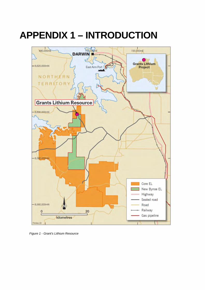
List of Figures Figure 1 - Grant’s Lithium Resource ........................................... 31
Figure 2 - Overview of Mine Site relative to Darwin ................... 32
Figure 3– Access Road take-off points from Cox Peninsula Rd and overall site layout (updated Feb 2019) at Grant’s ............................................................. 33
Figure 4 – Nominal distance between Centroids of the WRD and Pit (Generic methodology using PFS WRD and Pit shape) noting no material changes compared to updated designs 34
Figure 5 – Typical Sequencing of backfilling (Generic methodology using PFS WRD and Pit shape) noting no material changes compared to updated designs 35
Figure 6 – NT average rainfall, temperatures and evaporation rates (Knapton / Fuller Grant’s Lithium Groundwater Modelling Study Report v0.2 DRAFT 2018) 36
Figure 7 – Grant’s site layout showing TSF location within WRD37
Figure 8 – Underground decline from surface calculations ....... 38
Figure 9 – Excerpt from Core Exploration ASX Announcement 22 October 2018 showing underground potential at Grant’s ......................................... 40
Figure 10 – Excerpt from Core Exploration presentation to “Diggers and Dealers, WA 2018” showing underground potential at Grant’s ........................... 41
Figure 11 – Typical optimisation run for Grant’s Pit showing pit shell depths beyond current design of -180mRL (NOT FOR PUBLIC; INTERNAL DISTRIBUTION ONLY) 42
Figure 12 – Cost workup for backfilling from centroid of WRD to pit using Method 1 (Digger and truck fleet) .............................................................................. 44
Figure 13 – Pit backfilling cost inputs for Method 1 including backfill categorisation (waste rock only net of tailings) ................................................................ 46

Grant’s Pit Sterilisation Study February 2019 10 OF 46
1 INTRODUCTION
1.1 Scope
Innicon was approached by B Duncan (Core) to provide a ‘Sterilisation Report” to understand whether the proposed Grant’s Pit void, post open pit mining activities, should be backfilled. The study was to include a better understanding of:
• Pit void backfilling methodologies
• Climate
• Tailings storage
• Work, Health and Safety
• Underground mining
• Mine closure
• Environmental and Community
• Economic analysis
1.2 Objectives
The aim of the “Sterilisation Study” was to better understand any impacts and consequences due to backfilling the Grant’s open pit void and provide Core with conclusions and recommendations.
1.3 Guidelines
1.3.1 Project Methodology
Innicon used Core’s current LOM Schedule (based on a pending Definitive Feasibility Study to be released sometime in 2019) and supporting physicals from a recent tender process, current pit void backfilling methodologies and cost estimates from industry (including Innicon’s own experience), and various reports including water modelling reports, to support the Sterilisation Study. Innicon’s approach was to categorise a backfill inventory made up of tailings, waste rock and other material used for site surface infrastructure. Once the inventory was established, volumes for the varying types of backfill enabled costs to be worked up and differing backfill combinations to be determined. The pit void volume was calculated from the LOM Schedule (total volume mined from the pit) and distances from the centroid of the WRD to the centroid of the pit were tabled for inputs to calculate the cost of material placement and operational logistics.

Grant’s Pit Sterilisation Study February 2019 11 OF 46
Innicon understood that Core’s preferred methodology to place material into the pit was using the existing mine fleet (or similar) as well as considering any alternatives if they appeared to be a better solution. As part of the Study, Innicon assessed the impact and consequences that backfilling the pit would have on:
• any potential to exploit any underground resource beneath the pit; • mine closure goals; • work, health and safety of people and plant during backfill operations; • tailings already placed; and • overall economics of the project
Once the above was formulated, a series of approaches was finalised and a SWOT (in the form of Strengths and Weaknesses) carried out for each. Innicon then provided Conclusions and recommendations to Core. 1.4 Terms and Definitions
Au - Gold
BCM - Bank cubic metre (in this case the in-situ volume with no swell factor applied)
Core - Core Exploration Ltd
DMS - Dense Media Separation process to generate a saleable lithium concentrate
Digger - Nominal +100 tonne class excavator commonly used in open pit mining
DFS - Definitive Feasibility Study
Dozer - Bulldozer used to push waste, rock, ore or any loose material around
EIS - Environmental Impact Statement
IRR - Internal Rate of Return
JORC - Australasian Code for Reporting of Mineral Resource and Ore Reserves
Grant’s - Proposed Grant’s mine site
Innicon - Buxton Innicon Pty Ltd (Sean Buxton)
LCM - Loose cubic metre volume (includes a swell factor of 30%)
LOM - Life of Mine
ML - Mining Lease (application or other) granted by the NT government
MLCM / MBCM - Millions of either LCM or BCM
Grant’s Pit Sterilisation Study February 2019 12 OF 46
NPV - Net Present Value
NT - Northern Territory
PFS - Pre-feasibility Study
Pit - Grant’s Open Pit void
ROM - Run of Mine (relation to ROM Pad) where mined ore is stacked ready for processing
Study - this Sterilisation Study within this report
Swell Factor - Material expansion factor (30% for Core), when once excavated then placed
Truck - Nominal +70 tonne class dump truck commonly used in open pit mining
TSF - Tailings Storage Facility
UG - Underground
Waste - Waste rock from the waste rock dump
WRD - Waste Rock Dump which encapsulates 3 x TSF cells

Grant’s Pit Sterilisation Study February 2019 13 OF 46
1.5 Consultants used
Sean Buxton, Managing Director Buxton Innicon Pty Ltd - Experienced Operations / General Manager in both Open Pit & Underground Mines for over 28 years. Strong operations and technical professional specialising in Gold and and Base Metals, Feasibility Studies, greenfields mine startup, Heap Leach, Contractor and Project Management, Intellectual Property (IP) and Research and Development (R&D).
1.6 Disclaimer
The information contained in this document is solely for the use of the client(s) identified on the cover sheet, and for the purpose for which it has been prepared. Buxton Innicon Pty Ltd does not accept any liability for any claim arising out of or in connection with any of the information contained within this document. No party or individual shall copy, modify or publish any part of this document without written authorisation from Buxton Innicon Pty Ltd.
1.7 Location and Ownership
Core’s “Finniss Lithium Project” encompasses a large landholding in the Bynoe Tin Tantalum-Pegmatite Field. The Bynoe field is one of the most prospective areas for lithium in the NT and has many similarities to Greenbushes in WA, one of the world’s largest spodumene deposits.
The Finniss Lithium Project (Including the Grant’s Lithium Resource) is located approximately 32km west of Darwin on the Cox Peninsula area.
1.8 Tenements
The “Grants Lithium Resource” is located on Core’s 100% owned exploration tenement EL29698 adjacent to the Cox Peninsula Road, approximately 25 kilometres in a straight line from Darwin, the capital of the NT. A mineral lease ML31726 covering the proposed activities is under application.
1.9 Project History
Core’s, Northern Territory (NT) Lithium Project Includes the Mount Finniss Tin Tantalum Mine – the largest historically producing tin and tantalum pegmatite mine in the NT, and a further 25 historic tin tantalum pegmatite mines in the lithium rich Bynoe pegmatite field.
Core has been working towards both a PFS and DFS since late 2017. As part of the approvals’ process, this study will form part of a submission to relevant NT Regulatory bodies and a recent EIS Supplement and is required by early March 2019.

Grant’s Pit Sterilisation Study February 2019 14 OF 46
2 LITERATURE STUDY
2.1 Introduction
There have been no known studies / reviews for sterilisation of the proposed pit undertaken prior to this study. The only study that will be referred to was groundwater modelling study.
2.2 Ground Water Modelling
The following discussion re groundwater and further discussion in the document re a pit lake is from the DRAFT Report v0.2 by Knapton / Fuller, 2018, (Cloud GMS) – “Development of a Groundwater Model for the Grant’s Lithium Project” which outlined the development of a numerical model to assess groundwater impacts due to the mining of the pit.
The aquifer beneath the pit is a is a fractured and weathered rock aquifer with minor groundwater resource. Generally, there are few groundwater bores or users within 13km of the pit with historical bore yields in the area less than 0.5 L/s with groundwater intersected in the base of the weathered zone and where drilling intersects fracture zones.
Depth to groundwater ranges from less than 1 m in the wet season up to 5.5 m in the dry season. The main recharge mechanism is expected to be where water is added to groundwater through the percolation of rainfall over a widely distributed area. Evapotranspiration and diffuse discharge are likely to be the key groundwater discharge mechanisms. Groundwater in the shallow laterite and alluvial sediments is very fresh (<25 EC) and has similar chemical characteristics to rainfall (Knapton / Fuller, 2018).
Modelling indicates that generally, the pit void during the LOM and pit lake post closure, will not adversely affect groundwater levels or water quality.

Grant’s Pit Sterilisation Study February 2019 15 OF 46
3 PIT BACKFILLING
3.1 Introduction
There are several methods that could be used to backfill a pit void using the WRD as a source for material summarised below:
1. Digger and truck fleet with dozer push
2. Digger and mobile conveyor system with dozer push
3. Long Dozer push with large equipment
4. Hydraulic transfer
The author will describe the impacts, the consequences and undertake a brief Strengths and Weaknesses for each method.
3.1.1 Method 1 - Digger and truck fleet with dozer push
This method is a common method for the transfer of bulk waste rock material from a WRD to a pit edge for the purposes of backfilling. The method simply employs a digger and truck fleet most likely the same as that used for the mining of the pit. Mining fleet typically used for this application would consist of:
• 1 x +100 tonne excavator / digger
• 3 x 777F CAT Fixed body dump trucks
• 1 x 16M CAT Grader
• 2 x D10T CAT Dozers
• Ancillary support mobile plant including service truck, light vehicles
• Supporting technical, spotters and supervisory staff
For the purpose of this study, the productivity and cost workups assumed the digger to work from the WRD centroid and the trucks tipping at the pit centroid – nominally 1km. Two dozers were used with one supporting the digger on the WRD whilst the other dozer managed the live pit edge tip head. The grader ensures that running tracks for the trucking fleet is on grade, as smooth as can be on dumped, rough waste rock surfaces and clean of any debris that falls from the trays of trucks.
All backfilling activity was assumed to be done on dayshift only to ensure that there is full visibility of all areas during daylight hours. Visibility of tipheads is critical given this particular live tip face would be as deep as 225m noting that any early tell-tale signs of cracking at the tiphead, slumping of the live tip face or changes in tipping conditions at depth can only be seen in clear daylight. The tip face stands at a nominal 37 degrees which is the typical angle of repose for rock waste mixtures of fresh and oxide.

Grant’s Pit Sterilisation Study February 2019 16 OF 46
Prior to any work beginning a plan would be established as to the excavation sequencing on the WRD and the tiphead locations at varying areas around the pit. The plan would be risk assessed for environment and safety with all identified controls put in place to ensure that there is minimal chance of any incident.
The typical cycle for backfilling would be as follows:
• Daily inspections of the tip head at the edge of the pit for cracks or subsidence and to ensure that safe distances are maintained from where trucks will be tipping and where the live tiphead edge would be.
• Daily inspections of the pit floor, ramp and walls as well as the base of the live tip head
• Daily inspection of the WRD including to ensure that upcoming excavations will be stable, that the material being hauled is suitable (e.g. not too bog; particles too fine; too much moisture content), traffic management plan for the area is appropriate, and that excavations are according to a progressive established plan
• Once inspections are completed, the truck tipping location is setup with markers (e.g. coloured painted 44 gallon drums) and the excavation area on the WRD is setup with traffic delineation and survey marks for any limits to excavation
• Before tipping begins, a spotter is positioned at a point where they are in full view of the dozer operator, tiphead, tip face, pit ramps and walls, isolated from mobile equipment and in radio contact with the backfilling fleet. The spotters role is to immediately notify the truck and dozer operators of any changing condition that may lead to a sudden slumping or subsidence event.
• Diggers then establish a “dig face” up to 3.0m high and load the trucks
• Trucks then haul the waste material up to 1km on-way to the designated tipping point which is managed by the dozer and also marked the delineators
• Once the load is dumped, the dumped waste material is pushed to within a designated distance from the tiphead edge (e.g. 5m) noting that the dozer operator must maintain a set volume of material to be always in front the dozer blade which will in effect “shunt” the front material over the edge and down to up to 225m in a controlled manner. This material in front of the blade also will enable the dozer to slow down in the event of tip face subsidence.
• At the end of the shift, the area near the tiphead face is barricaded off (or isolated), all working areas left in a safe and stable condition and a survey done of the areas excavated and tipped to compare against the plan
• The cycle continues each dayshift as per the digging and tipping plan
Due to the tight, conical shape of the pit, the ramp sections which occur frequently on each pit wall as the pit gets deeper will be quickly “cutoff” as the live tiphead progresses both around the surface perimeter and outwards towards the pit centroid. This will mean that inspections of the base of the tip face and in the pit floor will generally be done from the surface.
Grant’s Pit Sterilisation Study February 2019 17 OF 46
The type of material to be tipped into the pit will also need to be carefully monitored. Unsuitable material would include material that has too many fines, clays or too much moisture. These materials when tipped on a large tip face have the potential to form thin layers that act as a slipping surface and will result in the bulk of the waste rock material tending to “slide” or “slip” over these layers rendering tiphead areas unsafe for both dozing and truck tipping due and therefore increasing the potential of large scale subsidence or uncontrolled slumping.
It is preferable to have dry weather when tipping material over the edge into the pit. If material becomes too wet, the same issue of rock “slipping” over rock suddenly poses a potential for sudden subsidence as described above. Wet weather also results in water runoff from the pit walls ending up at the base of the pit which will also be the base of the tip face. This can create a dangerous condition where at up 225m down the tip face, the “toe out” point can become soft, waterlogged and weak and this will trigger a sudden slump or subsidence all the way to the area where personnel and equipment are working.
Although there is the potential for serious conditions to develop using this method, if the right critical controls are put in place, the chance of a sudden large slump or subsidence is reduced and the potential to harm or damage equipment is minimised.
3.1.2 Method 2 - Digger and mobile conveyor system with dozer push
This method would be suited for transfer of bulk rock material from the WRD to the pit over any distance. There is still a mobile equipment fleet required in addition to a conveyor – stacker system including:
• 1 x +100 tonne excavator / digger
• 1 x 777F CAT Fixed body dump trucks
• 1 x 16M CAT Grader
• 2 x D10T CAT Dozers
• Mobile screening plant
• Rotating stacker conveyor system
• Ancillary support mobile plant including service truck, light vehicles
• Supporting technical, spotters and supervisory staff
This method would employ less personnel but has the disadvantage of requiring a screening plant to ensure a constant, homogenous, medium sized feed prior to material entering the conveyor system. A digger would feed a mobile screening plant and move in a sequential order across the WRD. Any material too large for the conveyor – stacker would be screened off and would need further placement by the digger into a truck. A large amount of capital would be required to set up this method noting that the truck, grader and 1 x dozer would be under utilised compared to Method 1.
One advantage of this method over others is that there would be less interaction and exposure of personnel and equipment at the pit tiphead.
Grant’s Pit Sterilisation Study February 2019 18 OF 46
For the purpose of this study, this method was not used as the basis for costing or analysis although it does warrant further study.
3.1.3 Method 3 - Long Dozer push with large equipment
This method would be suited to a situation where the distance between the WRD centroid and pit centroid was less than 600m (CAT Performance Handbook ED47) for a very large dozer e.g. CAT D11. The method simply employs multiple very large dozers pushing rock waste side by side from the WRD to pit tiphead.
For the purpose of this study, this method was not viable for Grant’s due to the large pushing distances and therefore not considered.
3.1.4 Method 4 - Hydraulic transfer
This method would be suited to a situation where the WRD was made up of mostly fines which would be transported as a slurry via a pipeline deposited into the pit.
For the purpose of this study, this method was not viable for Grant’s due to the large amount of water required for pumping, the complex and capital prohibitive pit dewatering setup, and the fact that the WRD is made of mostly waste rock with and therefore not considered.

Grant’s Pit Sterilisation Study February 2019 19 OF 46
4 BACKFILL MATERIAL CATEGORISATION
Innicon has based the costings and backfilling discussion on Method 1 (above). There are several backfilling materials available for the pit as follows:
• Waste rock that has been mined from the pit during the LOM and dumped on the WRD with a swell factor typically of 30% (LCM) of the in-situ volume (BCM). The WRD would undergo some compaction as it was built but when remobilised again it assumed that the material tipped into the pit will be the same (LCM) and that no further swell occurs. Particle sizing will vary from very small (-5mm) to medium (5mm to 1m) and large (+1.0m).
• Tailings from the wet pre-screening of ore before it enters the DMS processing circuit. Particle sizing will be -0.5mm pumped from the thickener tank to the TSF cells
• Rejects from the DMS processing of ore that do not report as a lithium concentrate saleable product for Core but does contain lithium grade. Particle sizing -6mm.
Total waste mined from the pit is 12.1 MBCM or 15.7 MLCM (swell factor of 30%). The pit backfill inventory can be split as follows:
• 2.042 MLCM committed to roads, dams and other infrastructure but not TSF requirements (see Figure 13)
• 13.681 MLCM rock waste in the WRD and diversion bund
o Note that of the waste remaining in the WRD includes waste committed to the base that forms the TSF cells and enough for a TSF cover on mine closure to ensure a water shedding structure remains totalling a minimum of 3.730 MLCM of – Innicon has not included any of these likely commits in the backfilling calculations
o Included in the available waste is the diversion bund which would require strategic removal during pit backfilling to prevent site and pit inundation from surface flooding
Innicon has assumed that all of the WRD waste rock material (13.681 MLCM) is available for backfilling (net of tailings within the TSF) including any waste tied up with the 2 x TSFs. This assumes that the TSF cells can remain intact for mine closure - this is to be discussed in the Tailings Storage and Mine Closure sections and a potential fatal flaw for a filled pit with a water shedding structure.
With reference to Figure 13, it can be seen that there is a backfill material deficit (2.139 MLCM) i.e. not enough material to fill the pit without deconstructing all site infrastructure earthworks which include access roads and critical dams which are required to enable backfilling activities over a +6 year backfilling period.

Grant’s Pit Sterilisation Study February 2019 20 OF 46
5 CLIMATE
When considering using Method 1 for the pit backfilling, the weather will play in important role. In the NT, there is typically 2 main seasons a “dry” (from May to September) and “wet” (from October to April the following year). Innicon will assume that the available time to backfill the pit as well as ensuring a safe live tiphead (i.e. minimal potential for mass rock to slip and cause sudden subsidence over a 225m long live tipping face) would be from mid April to mid October each year – a total of 6 months – generally the driest times in the NT (see Figure 6) Assuming that there are 30 days available each month, an equipment availability of 95%, then this would mean 28.5 / days would be available for pit backfilling. As described above, pit backfilling would be best done on dayshift meaning 28.5 dayshifts would be available each month. This leaves 6 months with 28.5 days available for a total of 171 dayshifts available each year for backfilling in dry conditions. If an additional 30 days are added assuming some dry days either side of the dry season and also assuming that water can be pumped from the pit safely (also keeping the live tip face toe out dry), then the total annual dayshifts available would be 201 dayshifts per year. The total expected shifts to backfill the pit are estimated at 1,963 shifts (see Figure 12 ) meaning that to completely fill the pit would take 9.8 years.

Grant’s Pit Sterilisation Study February 2019 21 OF 46
6 TAILINGS STORAGE
The WRD at Grant’s is a more complex structure than normal waste rock dumps.
By end of Grant’s LOM, the WRD will fully encapsulate 2 x TSF cells containing dewatered tailings from the feed preparation (wet screening) process prior to entering the DMS processing circuit (see Figure 7). The tailings particle sizes are nominally less then -0.5mm. In addition to encapsulated tailings, the WRD will store a larger fraction of -6mm “rejects” generated from the DMS process. The rejects are expected to contain lithium grade but not for consideration for Core for this LOM.
As described in Method 1 above, the tailings components of the WRD would not be considered for placement within the pit due to the high probability of slippery layers forming on the live tip face and therefore increasing the potential for a sudden subsidence of mass material. The rejects component would likely be separately stored for potential future processing (currently not being considered by Core).
Innicon has assumed the WRD encapsulating the 2 x TSF cells includes a 1.3m deep base upon which the cells themselves are constructed and would require at least 17.5m depth of waste rock cover not including a post stage of topsoil covering, contouring and seeding to establish a water shedding structure. The total waste that would be associated with the TSF would be 3.730 MLCM.
As discussed above in Backfill Material Categorisation, the waste associated with the TSF has been included in the available waste for pit backfilling – this assumption a fatal flaw for any mine closure water shedding structure over the pit surface footprint. If the TSF waste were to remain (likely requirement), this would mean the backfill material deficit which was 2.139 MLCM would increase to 5.870 MLCM – an amount that would mean leaving a pit lake rather than a water shedding structure.
If all the waste committed to encapsulate and form the base of the 2 x TSFs was used to replace the deficit, the cost would increase by greater than $1.0M (additional complexity of removal compared to excavating a WRD), and the tails would need to be remobilised and re-established into a new large TSF (not costed or included in the current LOM). Core currently has a very limited disturbance footprint on the ML and currently has no allowance for an additional TSF not encapsulated within the WRD. It would be estimated that from industry baseline data that a cost of $2.00 / tonne of tailings would be enough to re-establish a new TSF coming to an additional $1.2M (not costed or included in the current LOM).

Grant’s Pit Sterilisation Study February 2019 22 OF 46
7 SCHEDULING
It is unknown exactly what impact the backfilling of the void would have on the current LOM schedule except that it would be likely that the LOM duration would be extended to enable backfilling activities.
Any extension to the LOM schedule as it is currently will impact the NPV due to an extension of fixed overheads likely similar to that experienced during the production of concentrate given that a large portion of the mining fleet would need retaining to undertake backfilling activities.

Grant’s Pit Sterilisation Study February 2019 23 OF 46
8 UNDERGROUND MINING
Innicon understands that there is a lithium resource beneath the current Grant’s proposed pit design (see Figure 9 – Excerpt from Core Exploration ASX Announcement 22 October 2018 showing underground potential at Grant’s and Figure 10 – Excerpt from Core Exploration presentation to “Diggers and Dealers, WA 2018” showing underground potential at Grant’s).
Any backfilling of the pit void at the end of the LOM would mean that access to any underground mine via a portal from up to 162m beneath natural surface (within the pit) would not be possible. Instead a 1,296m equivalent access via a decline from surface would be required.
In order to establish a 1,296m decline from surface (to a nominal 162m below surface), a second means of egress would be required noting a single decline would be beyond secondary ventilation limits. This means a primary exhaust fan would be required to be setup. The 2 options available would be a second (or return air) decline with a primary exhaust fan, or a ventilation shaft and primary exhaust fan. Innicon will work up costs for a second decline option.
Innicon has assumed that to access the underground orebody beneath Grant’s, a 1 in 8 gradient twin decline developed from surface with 20m long truck loading, connection or infrastructure cuddies every 100m would be required. Total development metres to reach the equivalent 162m below the pit surface would be 2,851m. Additional ground support in the form of steel armoured tunnels (e.g. ARMCO) would be required to establish a surface portal. Most of waste committed to access roads and other infrastructure would still be required to support underground activities (see above discussion in Backfill Material Categorisation).
The total cost for the twin decline development and associated infrastructure would be $19.958M.
Grant’s Pit Sterilisation Study February 2019 24 OF 46
9 FUTURE MINING
If the Grant’s pit is backfilled, there is limited potential to undertake a future pit “cutback” to access further ore already delineated at the base of the pit but currently not economic. The additional cost to excavate the waste from the pit would be at least double the $53.004M cost to place the waste into the pit estimated at $106M.
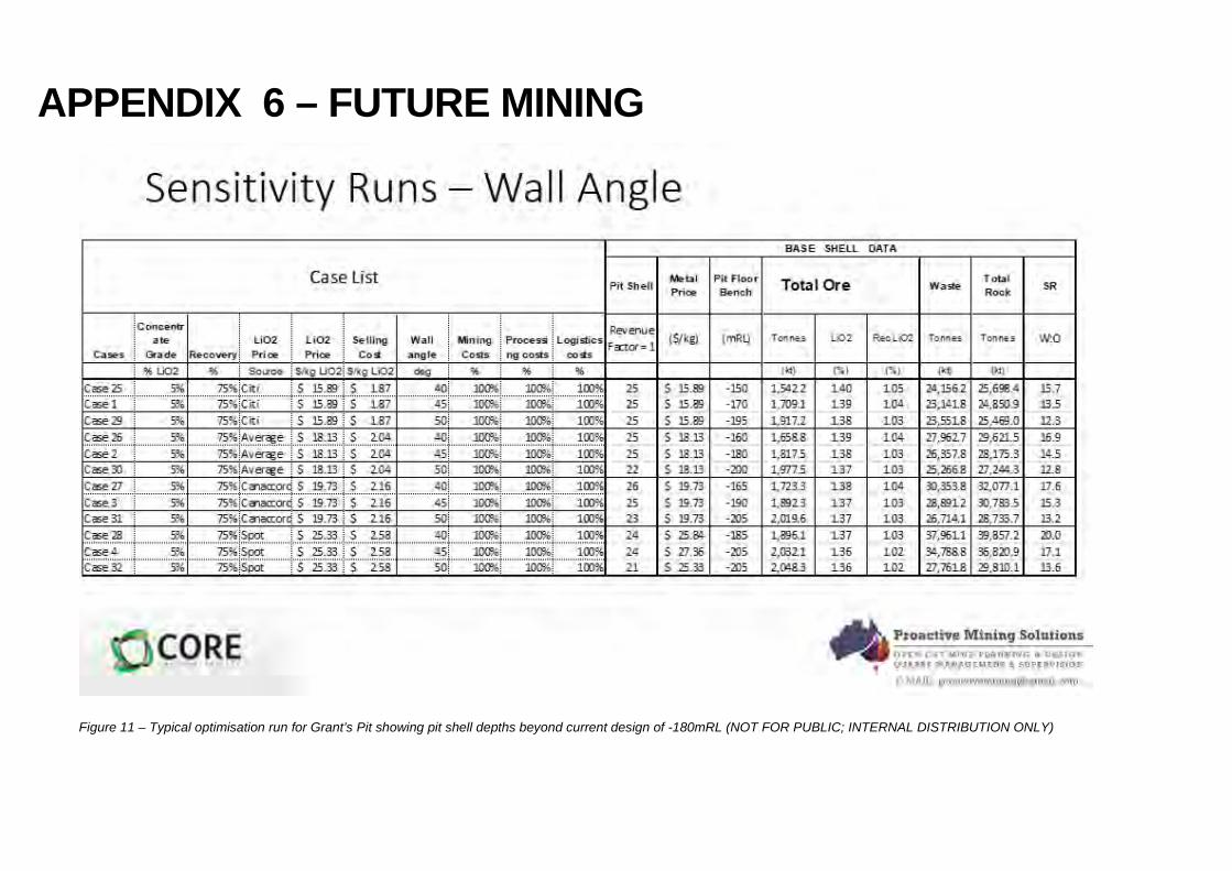
A recent pit optimisation shows that a pit depth of -205mRL is achievable given favourable economic conditions within reasonable sensitivity ranges. The current pit depth is -185mRL indicating that a pit cutback option for future mining would be an option given the right economic conditions.
Grant’s Pit Sterilisation Study February 2019 25 OF 46
10 ENVIRONMENT AND COMMUNITY
Innicon is not aware of the results of consultation with community re the preferred final amenity post mine closure. This report assumes that the community will not require the pit void for some other amenity (e.g. recreational purposes, commercial ventures etc) and therefore requires backfilling.

Grant’s Pit Sterilisation Study February 2019 26 OF 46
11 MINE CLOSURE
Innicon has assumed that there will be a deficit of material to completely fill the pit. This will mean that a water shedding final landform is not possible and a pit lake would result.
DRAFT Report v0.2 by Knapton / Fulton, 2018, (Cloud GMS) indicates that a pit lake will not adversely alter the groundwater flow regime generally. Innicon recommends further study in this area due to the shallow nature of the resulting pit lake compared to that referred in the report.
If the pit void is to be backfilled, the WRD would be classified as a “temporary structure” and would therefore not require progressive rehabilitation as all of the material within the WRD (net the tailings) would end up in the pit void.
Once a pit lake was established, there would still be a requirement for management of water that entered via surface runoff and additional surface water drainage and erosion and sediment control structures for the perpetuity of the lake – estimated cost up to $0.75M for construction with maintenance an additional cost. Innicon recommends further studies for design and costs associated with the setup and maintenance of pit lakes in the NT.
Grant’s Pit Sterilisation Study February 2019 27 OF 46
12 CONCLUSIONS AND RECOMMENDATIONS
12.1 Conclusions
12.1.1 Pit Backfill Methodology
There are likely 2 cost competitive methods viable to backfill the Grant’s pit void being Method 1 – Digger and truck fleet with dozer push, and Method 2 - Digger with mobile conveyor system and dozer push. All the other methods appear unviable due to a combination of the separation distances between the WRD and pit centroids, particle distribution and sizing, or cost.
A reasonable amount of site infrastructure post LOM production and mining will be required to support a pit backfilling operation including on site offices, road access, services and water for dust suppression.
The site diversion bund will need strategic decommissioning if the waste material is being used for pit backfill.
12.1.2 Backfill material
There is theoretically a small deficit of total mined waste for pit backfilling (15.7 MLCM for a 15.8 MLCM void).
There is actually a deficit of backfill material up to 2.139 MLCM (best case) or 5.869 MLCM (likely case if waste for 2 x TSF required to remain in place) due to 2.042 MLCM of waste already committed to other critical areas like water storage dams and access roads and diversion bunds.
Available waste for pit backfilling includes waste used to hold and eventually encapsulate the 2 x TSF’s in the WRD (3.730 MLCM).
12.1.3 Climate
Due to the nature of the climate in the NT, backfilling the pit is assumed to be viable for 6 months of the year in the dry season. Wet season climate is regarded as unsuitable for backfilling due to the potential for tiphead subsidence due to mass material sliding.
The pit dewatering infrastructure (e.g. power, pumps, piping, dams, roads etc) will be required to ensure that the pit base is reasonably dry near the live tip face toe out point due to ground water ingress and surface water pit wall runoff.
The total time to most safely backfill the pit, considering climate conditions, will be up to 9.8 years post the end of processing.
12.1.4 Tailings Storage
To re-mobilise and re-establish the TSF from its current proposed location (encapsulated within the WRD), would cost up to an additional $1.7M or an increased pit backfill placement cost of $54.704M (up from $53.004M).
The establishment of a new TSF as an alternative to the proposed WRD encapsulated option would increase the ML disturbance area by up to 25 ha.

Grant’s Pit Sterilisation Study February 2019 28 OF 46
12.1.5 Scheduling
An extension to the LOM Schedule and associated fixed overheads will occur if backfilling activities are required. There would need to be more investigation into the impact on the LOM schedule taking into consideration and special dumping and storage requirements for both tailings and waste material that would likely be required.
12.1.6 Underground Mining
If the pit is backfilled, the only way the resource beneath the pit can be accessed is from the surface either by a surface decline or via a shaft. If a decline option is considered compared to a portal access from deep within the pit void, the additional cost to establish a twin decline would be $19.958M.
12.1.7 Future Mining
If the Grant’s pit is backfilled, the void cannot be used as a water storage for future mining in the area. Core have identified multiple potential Lithium resources within a 25km radius of Grant’s. Initial groundwater studies (Knapton / Fuller 2018) show that there is limited water available in the region. Historically there a few bores with low yields that would not be suitable to support future mining.
Any dams in the near vicinity of Grant’s, such as Observation Hill Dam, would themselves not have sufficient storage capacities to support future mining activities.
If the Grant’s pit is backfilled, there is limited potential to undertake a future pit “cutback” to access further ore already delineated at the base of the pit but currently not economic.
12.1.8 Environment and Community
If the pit void is backfilled, there will be a deficit of backfill material which will result in a pit lake. It is unknown if community wish for a final amenity that provides for a commercial or recreational use post mine closure.
12.1.9 Mine Closure
In order to achieve a water shedding final landform over the pit footprint, a subsidence of 3m of the pit backfill has been assumed and a final surface of 1 in 100 sloping outwards from the pit centre has also been assumed. This has resulted in an additional 1.184 MLCM of material required for backfilling and has been included in the pit volume totals.
There is a deficit of backfill material in order to achieve a water shedding structure. This will result in a final landform of a pit lake.
A final landform of a pit lake will require additional erosion sediment controls and drainage structures and infrastructure to manage surface water ingress and runoff estimated at $0.75M noting the cost to maintain the lake in perpetuity has not been costed.

Grant’s Pit Sterilisation Study February 2019 29 OF 46
12.1.10 Economic Analysis
Core have indicated that the NPV for the Grant’s project would be $140M with an IRR of 142%. Innicon notes that a pit backfilling cost of $53.004M obviously reduces both the NPV and IRR noting that it still may not meet internal Core project return hurdles.
Core have also indicated that the Grant’s underground NPV would be much less than the Open Pit and yet to be finalised. Innicon notes that if the pit were to be backfilled, then, the cost of developing a decline from surface as an alternative to starting a decline from a nominal depth from surface of 162m from within the pit, would be and additional $19.958M which would not meet Core’s internal hurdle rate. In Core’s view the development of the underground resource beneath the Grant’s pit would not be considered if the pit was backfilled.

Grant’s Pit Sterilisation Study February 2019 30 OF 46
13 BIBLIOGRAPHY
Duncan, B. (2019) LOM Schedule spreadsheet (excel) - CoreEx_FS_LOM Schedule_RevE.xlsx
Knapton, A. and Fulton, S. (CloudGMS) (2018)
Development of a Groundwater Model for the Grants Lithium Project Draft Version 0.2
Buxton, S. (2018) Industry references including backfilling of an open pit in NSW
Buxton, S. (2018) 1800811_Schedule of Rates Tables - Mine Services Agreement.xlsx
Millbank, J. (Proactive Mining) (2018)
Grant’s Lithium Project – Prefeasibility Optimisation Study for Core Exploration, May 2018
APPENDIX 1 – INTRODUCTION
Figure 1 - Grant’s Lithium Resource

Figure 2 - Overview of Mine Site relative to Darwin

Figure 3– Access Road take-off points from Cox Peninsula Rd and overall site layout (updated Feb 2019) at Grant’s

APPENDIX 2 – PIT BACKFILLING
Figure 4 – Nominal distance between Centroids of the WRD and Pit (Generic methodology using PFS WRD and Pit shape) noting no material changes compared to updated designs

Figure 5 – Typical Sequencing of backfilling (Generic methodology using PFS WRD and Pit shape) noting no material changes compared to updated designs
Stage 1
Stage 2
Stage 3

APPENDIX 3 - CLIMATE
Figure 6 – NT average rainfall, temperatures and evaporation rates (Knapton / Fuller Grant’s Lithium Groundwater Modelling Study Report v0.2 DRAFT 2018)

APPENDIX 4 – TAILINGS STORAGE
Figure 7 – Grant’s site layout showing TSF location within WRD

APPENDIX 5 – UNDERGROUND
Figure 8 – Underground decline from surface calculations


Figure 9 – Excerpt from Core Exploration ASX Announcement 22 October 2018 showing underground potential at Grant’s

Figure 10 – Excerpt from Core Exploration presentation to “Diggers and Dealers, WA 2018” showing underground potential at Grant’s
APPENDIX 6 – FUTURE MINING
Figure 11 – Typical optimisation run for Grant’s Pit showing pit shell depths beyond current design of -180mRL (NOT FOR PUBLIC; INTERNAL DISTRIBUTION ONLY)

APPENDIX 7 – ECONOMIC ANALYSIS

Figure 12 – Cost workup for backfilling from centroid of WRD to pit using Method 1 (Digger and truck fleet)

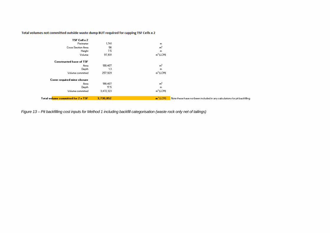
Figure 13 – Pit backfilling cost inputs for Method 1 including backfill categorisation (waste rock only net of tailings)