grain crop drying, handling and storage - fao
TRANSCRIPT
363
Chapter 16
Grain crop drying, handling and storage
IntroductIonAlthough in many parts of Africa certain crops can be produced throughout the year, the major food crops such as cereal grains and tubers, including potatoes, are normally seasonal crops. Consequently the food produced in one harvest period, which may last for only a few weeks, must be stored for gradual consumption until the next harvest, and seed must be held for the next season’s crop.
In addition, in a market that is not controlled, the value of any surplus crop tends to rise during the off-season period, provided that it is in a marketable condition. Therefore the principal aim of any storage system must be to maintain the crop in prime condition for as long as possible. The storage and handling methods should minimize losses, but must also be appropriate in relation to other factors, such as economies of scale, labour cost and availability, building costs and machinery cost.
GraIn dryInGThe handling and storage of grains will be discussed in an orderly sequence. First we discuss the requirements for safe storage, including the principles involved in both natural and artificial drying, followed by drying methods suitable for the small grower, as well as for the larger scale operations of cooperatives and commercial farms. Finally, various types of storage structures and systems, from family size up to commercial units, are discussed, together with management suggestions for preventing damage during the storage period.
Properties of grainsCereal grains are edible seeds and, as such, would eventually be released from the plant when fully mature. Grains can be divided into three groups; cereals (maize, wheat, millet, rice, etc.), pulses (beans, peas, cowpeas, etc.), and oil seeds (soyabeans, sunflower, linseed, etc.).
requirements for safe storageCrops left standing un-harvested start to show diminishing quantitative and qualitative returns through shatter losses and attacks by insects, mould, birds and rodents. It is therefore important to complete harvesting as soon as possible. In addition, it is necessary to remove dust and contaminants, which can include insects, and vegetable material, such as bits of straw and chaff and weed seeds. These will fill up pore spaces
within the crop, inhibiting air movement and adding to any possible spoilage problems. The crop must therefore be clean.
One of the most critical physiological factors in successful grain storage is the moisture content of the crop. High moisture content leads to storage problems because it encourages fungal and insect problems, respiration and germination. However, moisture content in the growing crop is naturally high and only starts to decrease as the crop reaches maturity and the grains are drying. In their natural state, the seeds would have a period of dormancy and then germinate either when re-wetted by rain or as a result of a naturally adequate moisture content.
Another major factor influencing spoilage is temperature. Grains are biologically active and respire during storage. One of the products of respiration is heat, and reducing the temperature of the crop can help to diminish the rate of respiration, thereby lengthening the storage life by lessening the possibility of germination. Another major temperature effect is on the activity of insect and fungal problems. With lower temperatures, the metabolic rate of insects and fungi decreases and consequently so does the activity causing spoilage.
A damp or warm spot in grain will increase the rate of respiration. In addition to heat, another product of respiration is moisture. The heat and moisture from such a ‘hot spot’ can spread by convection, encouraging moulds and bacteria, which in turn respire and give off more heat and moisture. It therefore becomes a self-generating process. Insect activity also increases with a rise in temperature.
These spoilage mechanisms can also affect the viability of grain required for seed or malting, where the inability to germinate would render it unmarketable.
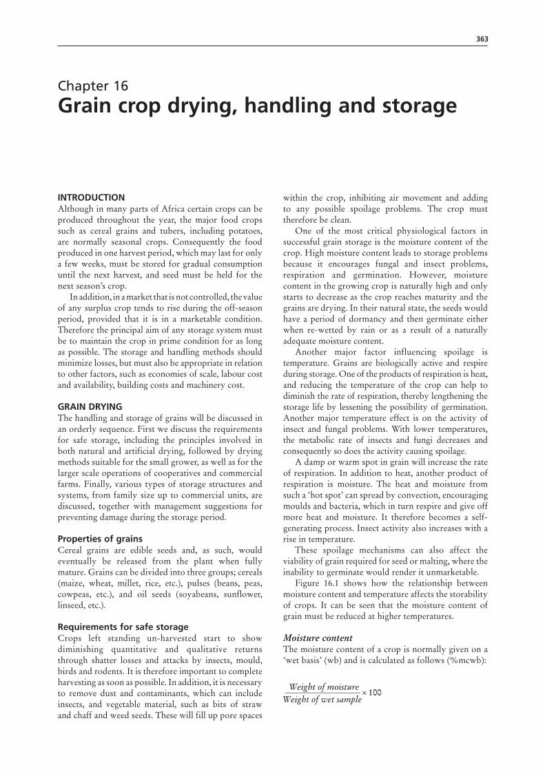
Figure 16.1 shows how the relationship between moisture content and temperature affects the storability of crops. It can be seen that the moisture content of grain must be reduced at higher temperatures.
Moisture contentThe moisture content of a crop is normally given on a ‘wet basis’ (wb) and is calculated as follows (%mcwb):
100×Weight of wet sample
Weight of moisture
on wet basis (wb) or%20100
10020=
×
%2580
10020on dry basis (db)=
×
364 Rural structures in the tropics: design and development
Figure 16.1 Effects in storage at different temperatures and moisture content
Occasionally ‘dry basis’ (db) moisture content is given and it is important to know which has been used.
For example, if 100 kg of moist grain is dried and loses 20 kg of water, the moisture content is:
Grain will normally be harvested at a moisture content of 18–25 percent (wb), although it can be substantially higher or lower depending on many factors (such as the stage of maturity, season, weather pattern and drying facilities).
Moisture content measurementMoisture can be determined in the laboratory by a number of methods, the most accurate of which are the oven-drying method and the distillation method; these are normally taken as references for moisture meters used under field conditions.
Laboratory methods require a representative sample of the grain. As the moisture content is unlikely to be uniform throughout a batch of grain, it is essential that:
• Either several samples are taken and tested, or a sample is taken from several places, thoroughly mixed, placed on a clean surface and quartered, with the procedure repeated until a suitable sized sample is obtained.
• Or the sample taken is kept in a sealed container (e.g. tightly fitting tin, bottle or plastic bag) between the time of sampling and the time of determining the moisture content.
The oven-drying method is the most straight forward and requires an accurately weighed sample of grain to
40
A
B
C
30
20
10
0 10 15 20 25Moisture (percent)
Safe
Tem
per
atu
re °
C Insectheating
Fall ingermination
Fungalheating
100×Weight of wet sample
Weight of moisture
on wet basis (wb) or%20100
10020=
×
%2580
10020on dry basis (db)=
×
100×Weight of wet sample
Weight of moisture
on wet basis (wb) or%20100
10020=
×
%2580
10020on dry basis (db)=
×
be dried for a period of time and then re-weighed. The scales should preferably be electronic unless a large enough sample is used, in which case good mechanical scales can be used.
The rapid-oven method is one of a number of faster laboratory methods. These methods range from simple, inexpensive pieces of equipment to highly sophisticated and expensive instruments. A typical simple method consists of shining an infrared lamp on a balance pan containing a ground sample of approximately 5 grams. The sample is exposed to the intense heat of the lamp for a predetermined period and the loss in weight is shown on a scale calibrated for percentage moisture content.
The salt-jar method is a simple field method for determining whether maize is dry enough for storage in bags. A teaspoon full of dry non-iodized salt is placed in a thoroughly dry jar (or bottle) with a tight cover. The salt should not stick to the sides of the jar when it is rolled. Then a cob of maize is shelled, the kernels placed in the jar and the cover sealed tightly. The jar is then shaken and rolled gently for 2–3 minutes. If the salt does not lump or adhere to the sides of the jar, the moisture is usually below 15 percent.
Moisture meters measure one or more electrical properties of the grain that are closely related to moisture content. Although acetylene and hair hygrometer measurement techniques have been used in the past, electrical moisture meters are now the most commonly used type of moisture meter. Developments in electronics have led to the manufacture of cheap and easy-to-use electronic meters that are also quite accurate. These are sold under different brand names.
Relative humidityRelative humidity (RH) as a measure of air moisture is defined in Chapter 12. It is a useful factor for grain drying. The relative humidity of ventilating air indicates how much, if any, moisture can be removed from the grain with unheated air, and is a basis for deciding on ventilation rates and air temperatures.
Relative humidity measurementOf the devices available for measuring relative humidity, one of the simplest and most accurate is a psychrometer. The temperatures of the wet-bulb and dry-bulb thermometers mounted on the instrument are noted and the values are used with a psychrometric chart. In fan systems, the psychrometer may simply be held in the airstream to obtain a reading.
drying theory
Equilibrium moisture contentAny hygroscopic material (including grain) has its own characteristic balance (or equilibrium) between the moisture it contains and the water vapour in the air with which it is in contact. This is known as the equilibrium moisture content (EMC). When food grains
365Chapter 16 – Grain crop drying, handling and storage
containing a certain amount of moisture are exposed to air, moisture moves from the grain to the air, or vice versa, until there is a balance between the moisture in the grain and in the air.
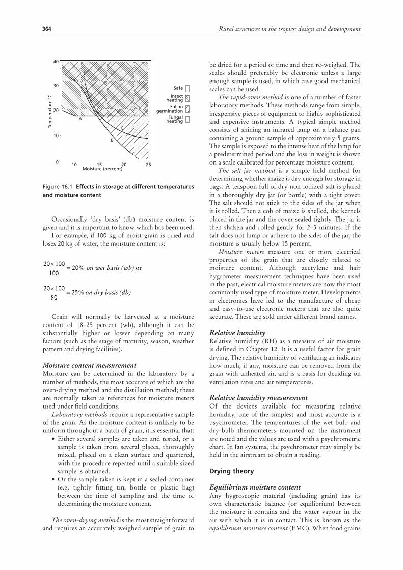
Each food grain has a characteristic equilibrium curve obtained by plotting a graph of moisture content against the relative humidity and temperature of the air. Curves for some common food grains are given in Figure 16.2. These values must be considered only as a guide because the equilibrium values of different types and varieties of grain vary. The EMC will also vary slightly with temperature. For most cereals, it will drop by approximately 0.5 percent for every 10 °C temperature rise at the same percentage relative humidity of the air.
Figure 16.2 Equilibrium moisture content for different crops
Table 16.1 shows moisture content equilibrium values for a range of produce at 70 percent relative humidity and 27 °C (the maximum acceptable level for storage of any sample).
Table 16.1Equilibrium moisture content (EMc) values at 27 °c and 70 percent relative humidity
crop EMc
Maize 13.5
Wheat 13.5
Sorghum 13.5
Millet 16.0
Paddy 15.0
Rice 13.0
Cowpeas 15.0
beans 15.0
Groundnuts (shelled) 7.0
Copra 7.0
31 2
1 Rice2 Maize3 Wheat
13
6
10
20
30
40
50
60
70
80
90
100RH%at25°C
8 10 12 14 16 18MC%
2
As sacks are porous and allow air to circulate readily through the crop, it is generally acceptable to allow the grain to be stored at a moisture content that is 1–2 percent higher than in bins or containers with non-porous walls.
The storage of grains can also be affected by the atmosphere, in addition to temperature and moisture content. If damp grain is held in a sealed container, the respiration of grain and insects will consume the available oxygen. As the oxygen is depleted, it is replaced with carbon dioxide. This, in turn, inhibits the activity of the insects and fungal problems, which will decrease to the point that it virtually ceases. However, storage in this manner can cause tainting of the grain, which renders it less acceptable for human consumption.
Storage of seed grain requires conditions that will not only maintain peak viability but will avoid also all possibility of germination while in storage. High moisture content and low oxygen may decrease viability and therefore should be avoided for seed storage. At the same time, to avoid any danger of germination or fungal and insect damage while in storage, seed should be dried 1–2 percent more than for human consumption. Additionally, it is important to keep the temperature of the seed as low as possible.
Temperature and psychrometrics of dryingGrain to be stored in bins or sacks may have too high a temperature or too high a moisture content, or both. If ambient temperatures are low, then air alone may cool the stored grain enough to prevent mould and insect damage while the moisture content is being slowly reduced to a safe level. If the air temperature is too high (over 10 °C), drying may be hastened by heating, as heating the air further increases its capacity to absorb moisture.
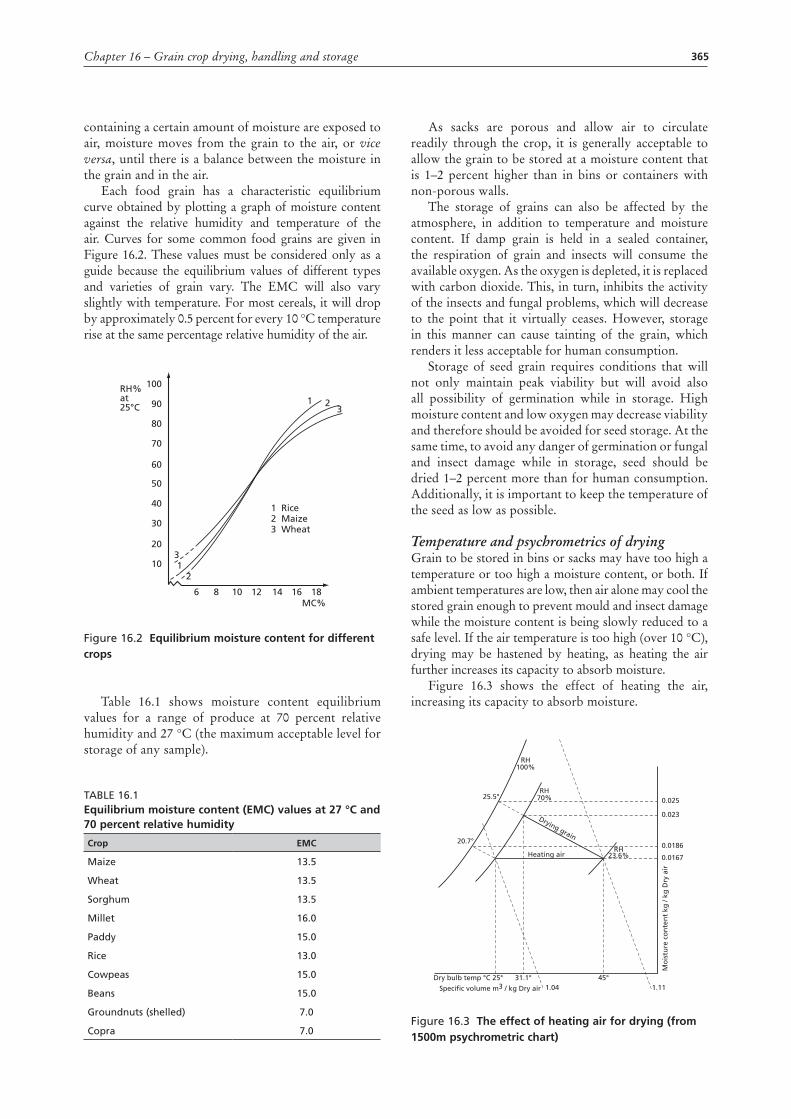
Figure 16.3 shows the effect of heating the air, increasing its capacity to absorb moisture.
Figure 16.3 the effect of heating air for drying (from 1500m psychrometric chart)
Heating air
Mo
istu
re c
on
ten
t kg
/ kg
Dry
air
Specific volume m3 / kg Dry air
Dry bulb temp °C 25° 45°1.04 1.11
31.1°
RH23.6%
0.025
0.023
0.0186
0.0167
RH70%
RH100%
25.5°
20.7°
Drying grain
366 Rural structures in the tropics: design and development
Example: The ambient air at 25 °C and 70 percent RH is heated to 45 °C and 24 percent RH. When passing through the grain, it gains enough moisture to again reach 70 percent RH while the temperature drops to 30.1 °C. Each kilogram of air would then have removed (0.023 - 0.0167) = 0.0063 kg of moisture. Whether the air returns to 70 percent RH or to some other level will depend on the air velocity through the grain.
Loss of moistureAs grain dries, it releases its moisture into the drying air and consequently loses weight.
The weight of grain after drying may be found using the following equation:
where:W1 = Weight of undried grain (kg) W2 = Weight of dried grain (kg) M1 = Moisture content of undried grain (percent) M2 = Moisture content of dried grain (percent).
For example, if 200 kg of peas at 32 percent moisture content are dried to 19 percent moisture content, what is the weight of the dried peas?
When the moisture content of the grain to be dried has been determined, it is possible to check the progress of the drying process by using the following procedure.
100 M2
(M1 − M2)W1W1W2 −−=
W2 167.9 kg32.120019100
200 (32 − 19)200 =−=
−−=
100W2
W1 (100 − M1)M2 −=
100 M2
(M1 − M2)W1W1W2 −−=
W2 167.9 kg32.120019100
200 (32 − 19)200 =−=
−−=
100W2
W1 (100 − M1)M2 −=
Before drying starts, place a weighed sample of the undried grain in a porous sack and bury it in the upper layer of the grain in the grain bin. At any time during the drying process, the sack may be removed, weighed, and returned to the bin. Then, using the initial weight, the initial moisture content and the newly observed weight in the following equation, the current moisture content at that specific level may be calculated:
drying systemsThe range of systems available for drying grains varies from thin-layer drying in the sun or a simple maize crib to expensive mechanized systems such as continuous-flow dryers. The choice is governed by a number of factors, including:
Rate of harvest: The capacity of the system must be able to keep pace with the rate at which the grain arrives at the store on a daily basis. It is essential that loading and drying does not hold up the harvest.
Total volume to be dried: This may not be the total volume of the crop. If harvesting normally starts as the rainy season is ending, it may be necessary to dry the early part of the harvest, but not the later part.
Storage system: In many cases, the storage system and the drying system may be the same structure. For example a ventilated maize crib (see Figure 16.5), used for drying the crop naturally, is likely to be used to store the shelled crop in bags later. Some bin-drying systems have a similar dual purpose.
Cost: Both capital cost and running cost should be taken into account.
100 M2
(M1 − M2)W1W1W2 −−=
W2 167.9 kg32.120019100
200 (32 − 19)200 =−=
−−=
100W2
W1 (100 − M1)M2 −=
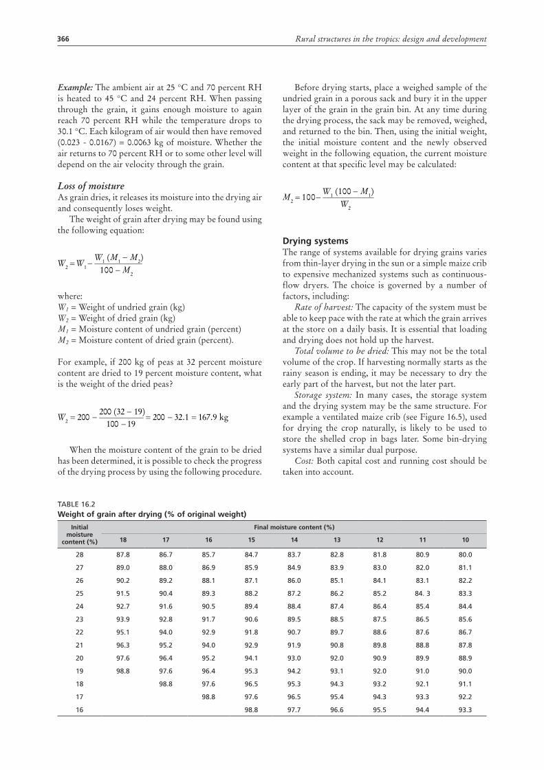
Table 16.2Weight of grain after drying (% of original weight)
Initial moisture
content (%)
Final moisture content (%)
18 17 16 15 14 13 12 11 10
28 87.8 86.7 85.7 84.7 83.7 82.8 81.8 80.9 80.0
27 89.0 88.0 86.9 85.9 84.9 83.9 83.0 82.0 81.1
26 90.2 89.2 88.1 87.1 86.0 85.1 84.1 83.1 82.2
25 91.5 90.4 89.3 88.2 87.2 86.2 85.2 84. 3 83.3
24 92.7 91.6 90.5 89.4 88.4 87.4 86.4 85.4 84.4
23 93.9 92.8 91.7 90.6 89.5 88.5 87.5 86.5 85.6
22 95.1 94.0 92.9 91.8 90.7 89.7 88.6 87.6 86.7
21 96.3 95.2 94.0 92.9 91.9 90.8 89.8 88.8 87.8
20 97.6 96.4 95.2 94.1 93.0 92.0 90.9 89.9 88.9
19 98.8 97.6 96.4 95.3 94.2 93.1 92.0 91.0 90.0
18 98.8 97.6 96.5 95.3 94.3 93.2 92.1 91.1
17 98.8 97.6 96.5 95.4 94.3 93.3 92.2
16 98.8 97.7 96.6 95.5 94.4 93.3
367Chapter 16 – Grain crop drying, handling and storage
Flexibility: The likelihood of different crops requiring drying should be considered.
Drying systems fall into two main groups:Natural drying using ambient air temperature and
either direct sunlight or natural air movement through the crop.
Artificial drying using mechanical means (e.g. a fan) to move air through the crop, with the air being either at ambient temperature or artificially heated.
Additionally, drying can be considered in terms of the thickness of the bed of grain being dried, i.e. either shallow-layer (or thin-layer) drying or deep-bed drying. Natural drying requires the grain to be in shallow layers, whereas certain fans can push air through grain several metres deep.
natural dryingThe traditional methods used by farmers for drying grain rely on natural air movement to reduce moisture content to a safe level for storage. In addition, they may utilize the extra drying capacity gained by exposing the produce to the sun. With good ventilation through the store, the grain can be harvested just after it is ripe (around 30 percent MC for maize) but most methods allow some of the drying to take place naturally while the crop is still standing in the field.
Natural drying may be divided in three main methods:
• Drying in the field before harvesting.• Drying in shallow layers and exposing to sun and
wind on a surface that prevents moisture from the ground from reaching the produce.
• Drying in, or on, a structure that has open sides to permit air movement through the mass.
Field dryingThe method of leaving the crop standing in the field for drying is popular in areas where maturity of the crop coincides with the beginning of a dry season. However, a crop left unharvested is exposed to attack by insects, birds, rodents, wild animals, strong winds and occasional rain showers, which can damage and reduce the crop considerably. These factors are particularly important with the new, improved high-yielding crop varieties, which are often more susceptible to damage from the environment than the traditional varieties. For instance, a hybrid maize cob has less leaf cover than the cob of traditional maize varieties and is therefore more open to attack by insects and birds.
Field drying of the crop will also delay clearing of the field. This should be taken into account in areas where the field needs to be prepared for a second rainy season, or where the humidity is high enough at the end of the growing season to allow for an additional crop, such as beans. It is also not feasible in irrigated fields where higher cropping intensity requires early and/or timely harvesting.
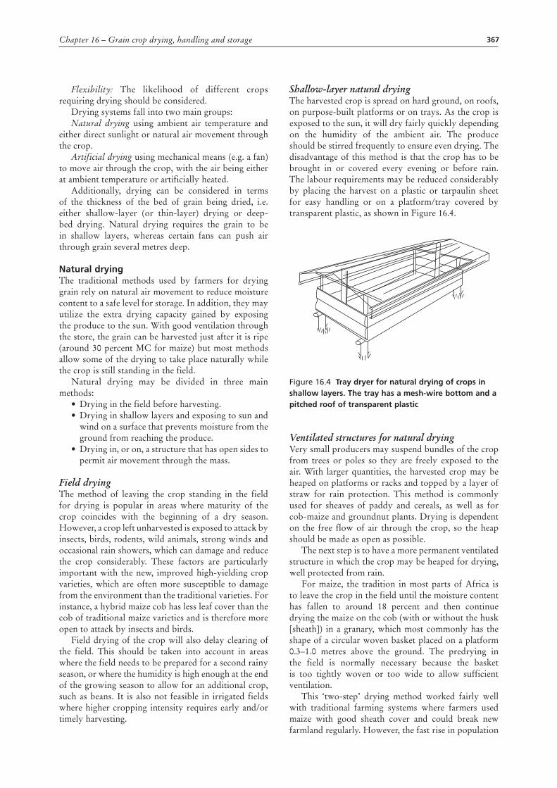
Shallow-layer natural dryingThe harvested crop is spread on hard ground, on roofs, on purpose-built platforms or on trays. As the crop is exposed to the sun, it will dry fairly quickly depending on the humidity of the ambient air. The produce should be stirred frequently to ensure even drying. The disadvantage of this method is that the crop has to be brought in or covered every evening or before rain. The labour requirements may be reduced considerably by placing the harvest on a plastic or tarpaulin sheet for easy handling or on a platform/tray covered by transparent plastic, as shown in Figure 16.4.
Figure 16.4 tray dryer for natural drying of crops in shallow layers. the tray has a mesh-wire bottom and a pitched roof of transparent plastic
Ventilated structures for natural dryingVery small producers may suspend bundles of the crop from trees or poles so they are freely exposed to the air. With larger quantities, the harvested crop may be heaped on platforms or racks and topped by a layer of straw for rain protection. This method is commonly used for sheaves of paddy and cereals, as well as for cob-maize and groundnut plants. Drying is dependent on the free flow of air through the crop, so the heap should be made as open as possible.
The next step is to have a more permanent ventilated structure in which the crop may be heaped for drying, well protected from rain.
For maize, the tradition in most parts of Africa is to leave the crop in the field until the moisture content has fallen to around 18 percent and then continue drying the maize on the cob (with or without the husk [sheath]) in a granary, which most commonly has the shape of a circular woven basket placed on a platform 0.3–1.0 metres above the ground. The predrying in the field is normally necessary because the basket is too tightly woven or too wide to allow sufficient ventilation.
This ‘two-step’ drying method worked fairly well with traditional farming systems where farmers used maize with good sheath cover and could break new farmland regularly. However, the fast rise in population
368 Rural structures in the tropics: design and development
experienced in many countries has resulted in a scarcity of good land, which forces farmers to use the same land for the same crop year after year. In most cases this leads to an accumulation of pests (e.g. insects). This, together with the higher susceptibility to insect attack of most improved high-yielding crop varieties (see the ‘Field Drying’ section), requires the crop to be harvested as early as possible, just after maturity, and moved away from the field for quick drying and safe storage.
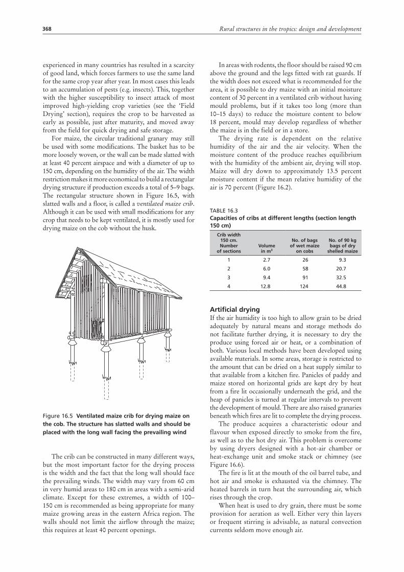
For maize, the circular traditional granary may still be used with some modifications. The basket has to be more loosely woven, or the wall can be made slatted with at least 40 percent airspace and with a diameter of up to 150 cm, depending on the humidity of the air. The width restriction makes it more economical to build a rectangular drying structure if production exceeds a total of 5–9 bags. The rectangular structure shown in Figure 16.5, with slatted walls and a floor, is called a ventilated maize crib. Although it can be used with small modifications for any crop that needs to be kept ventilated, it is mostly used for drying maize on the cob without the husk.
Figure 16.5 Ventilated maize crib for drying maize on the cob. the structure has slatted walls and should be placed with the long wall facing the prevailing wind
The crib can be constructed in many different ways, but the most important factor for the drying process is the width and the fact that the long wall should face the prevailing winds. The width may vary from 60 cm in very humid areas to 180 cm in areas with a semi-arid climate. Except for these extremes, a width of 100–150 cm is recommended as being appropriate for many maize growing areas in the eastern Africa region. The walls should not limit the airflow through the maize; this requires at least 40 percent openings.
In areas with rodents, the floor should be raised 90 cm above the ground and the legs fitted with rat guards. If the width does not exceed what is recommended for the area, it is possible to dry maize with an initial moisture content of 30 percent in a ventilated crib without having mould problems, but if it takes too long (more than 10–15 days) to reduce the moisture content to below 18 percent, mould may develop regardless of whether the maize is in the field or in a store.
The drying rate is dependent on the relative humidity of the air and the air velocity. When the moisture content of the produce reaches equilibrium with the humidity of the ambient air, drying will stop. Maize will dry down to approximately 13.5 percent moisture content if the mean relative humidity of the air is 70 percent (Figure 16.2).
Table 16.3capacities of cribs at different lengths (section length 150 cm)
crib width 150 cm. number
of sectionsVolume in m3
no. of bags of wet maize
on cobs
no. of 90 kg bags of dry
shelled maize
1 2.7 26 9.3
2 6.0 58 20.7
3 9.4 91 32.5
4 12.8 124 44.8
artificial dryingIf the air humidity is too high to allow grain to be dried adequately by natural means and storage methods do not facilitate further drying, it is necessary to dry the produce using forced air or heat, or a combination of both. Various local methods have been developed using available materials. In some areas, storage is restricted to the amount that can be dried on a heat supply similar to that available from a kitchen fire. Panicles of paddy and maize stored on horizontal grids are kept dry by heat from a fire lit occasionally underneath the grid, and the heap of panicles is turned at regular intervals to prevent the development of mould. There are also raised granaries beneath which fires are lit to complete the drying process.
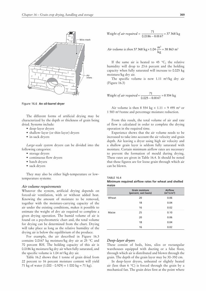
The produce acquires a characteristic odour and flavour when exposed directly to smoke from the fire, as well as to the hot dry air. This problem is overcome by using dryers designed with a hot-air chamber or heat-exchange unit and smoke stack or chimney (see Figure 16.6).
The fire is lit at the mouth of the oil barrel tube, and hot air and smoke is exhausted via the chimney. The heated barrels in turn heat the surrounding air, which rises through the crop.
When heat is used to dry grain, there must be some provision for aeration as well. Either very thin layers or frequent stirring is advisable, as natural convection currents seldom move enough air.
369Chapter 16 – Grain crop drying, handling and storage
Figure 16.6 an oil-barrel dryer
The different forms of artificial drying may be characterized by the depth or thickness of grain being dried. Systems include:
• deep-layer dryers• shallow-layer (or thin-layer) dryers• in-sack dryers
Large-scale system dryers can be divided into the following categories:
• storage dryers • continuous flow dryers • batch dryers • sack dryers
They may also be either high-temperature or low-temperature systems.
Air volume requirementsWhatever the system, artificial drying depends on forced-air ventilation, with or without added heat. Knowing the amount of moisture to be removed, together with the moisture-carrying capacity of the air under the existing conditions, makes it possible to estimate the weight of dry air required to complete a given drying operation. The humid volume of air is found on a psychrometric chart and, the total volume for drying can be determined from the chart. Drying will take place as long as the relative humidity of the drying air is below the equilibrium of the produce.
For example, the air described in Figure 16.3 contains 0.0167 kg moisture/kg dry air at 25 °C and 70 percent RH. The holding capacity of this air is 0.0186 kg moisture/kg dry air when fully saturated, and the specific volume is 1.04 m³/kg dry air.
Table 16.2 shows that 1 tonne of grain dried from 22 percent to 16 percent moisture content will yield 71 kg of water (1.000 - 0.929) × 1 000 kg = 71 kg).
Wire mesh
Air inlets
If the same air is heated to 45 °C, the relative humidity will drop to 23.6 percent and the holding capacity when fully saturated will increase to 0.025 kg moisture/kg dry air.
The specific volume is now 1.11 m³/kg dry air (Figure 16.3)
Air volume is then 8 554 kg × 1.11 = 9 495 m³ or 1 583 m³/tonne and percentage moisture reduction.
From this result, the total volume of air and rate of flow is calculated in order to complete the drying operation in the required time.
Experience shows that the air volume needs to be increased to take into account the air velocity and grain depth. Air leaving a dryer using high air velocity and a shallow grain layer is seldom fully saturated with moisture. Certain minimum airflow rates are necessary to prevent the formation of mould during drying. These rates are given in Table 16.4. It should be noted that these figures are for loose grain through which air can be blown.
Table 16.4Minimum required airflow rates for wheat and shelled maize
Grain moisture (percent, wet basis)
airflow (m3/s/m2)
Wheat 20 0.06
18 0.04
16 0.02
Maize 25 0.10
20 0.06
18 0.04
16 0.02
Deep-layer dryersThese consist of beds, bins, silos or rectangular warehouses equipped with ducting or a false floor, through which air is distributed and blown through the grain. The depth of the grain layer may be 30–350 cm.
In deep-layer dryers, unheated or slightly heated air (less than 6 °C) is forced through the grain by a mechanical fan. The grain dries first at the point where
Weight of air required 37 368 kg0.0186 − 0.0167
71==
38 863 m304.137 368 kgkgm3
Air volume is then =×
Weight of air required 37 368 kg0.0186 − 0.0167
71==
38 863 m304.137 368 kgkgm3
Air volume is then =×
Weight of air required 8 554 kg0.025 − 0.0167
71==
370 Rural structures in the tropics: design and development
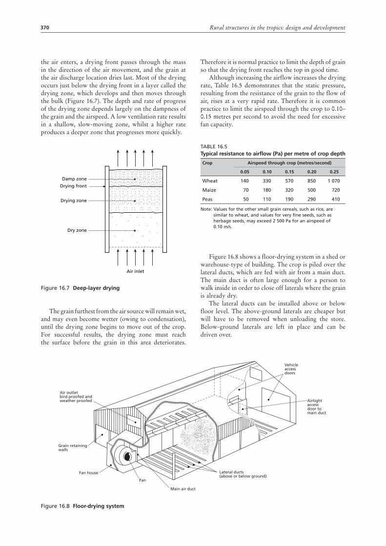
the air enters, a drying front passes through the mass in the direction of the air movement, and the grain at the air discharge location dries last. Most of the drying occurs just below the drying front in a layer called the drying zone, which develops and then moves through the bulk (Figure 16.7). The depth and rate of progress of the drying zone depends largely on the dampness of the grain and the airspeed. A low ventilation rate results in a shallow, slow-moving zone, whilst a higher rate produces a deeper zone that progresses more quickly.
Figure 16.7 deep-layer drying
The grain furthest from the air source will remain wet, and may even become wetter (owing to condensation), until the drying zone begins to move out of the crop. For successful results, the drying zone must reach the surface before the grain in this area deteriorates.
Damp zone
Drying front
Drying zone
Dry zone
Air inlet
Therefore it is normal practice to limit the depth of grain so that the drying front reaches the top in good time.
Although increasing the airflow increases the drying rate, Table 16.5 demonstrates that the static pressure, resulting from the resistance of the grain to the flow of air, rises at a very rapid rate. Therefore it is common practice to limit the airspeed through the crop to 0.10–0.15 metres per second to avoid the need for excessive fan capacity.
Table 16.5typical resistance to airflow (Pa) per metre of crop depth
crop airspeed through crop (metres/second)
0.05 0.10 0.15 0.20 0.25
Wheat 140 330 570 850 1 070
Maize 70 180 320 500 720
Peas 50 110 190 290 410
Note: Values for the other small grain cereals, such as rice, are similar to wheat, and values for very fine seeds, such as herbage seeds, may exceed 2 500 Pa for an airspeed of 0.10 m/s.
Figure 16.8 shows a floor-drying system in a shed or warehouse-type of building. The crop is piled over the lateral ducts, which are fed with air from a main duct. The main duct is often large enough for a person to walk inside in order to close off laterals where the grain is already dry.
The lateral ducts can be installed above or below floor level. The above-ground laterals are cheaper but will have to be removed when unloading the store. Below-ground laterals are left in place and can be driven over.
Figure 16.8 Floor-drying system
Air outlet bird proofed andweather proofed
Grain retainingwalls
Fan house
Fan
Main air duct
Lateral ducts(above or below ground)
Airtightaccessdoor tomain duct
Vehicleaccessdoors
371Chapter 16 – Grain crop drying, handling and storage
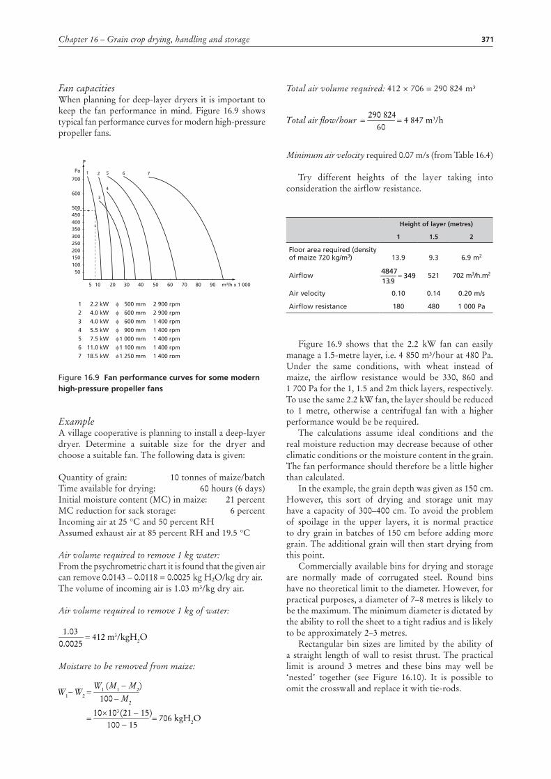
Fan capacitiesWhen planning for deep-layer dryers it is important to keep the fan performance in mind. Figure 16.9 shows typical fan performance curves for modern high-pressure propeller fans.
Figure 16.9 Fan performance curves for some modern high-pressure propeller fans
ExampleA village cooperative is planning to install a deep-layer dryer. Determine a suitable size for the dryer and choose a suitable fan. The following data is given:
Quantity of grain: 10 tonnes of maize/batchTime available for drying: 60 hours (6 days)Initial moisture content (MC) in maize: 21 percentMC reduction for sack storage: 6 percentIncoming air at 25 °C and 50 percent RHAssumed exhaust air at 85 percent RH and 19.5 °C
Air volume required to remove 1 kg water:From the psychrometric chart it is found that the given air can remove 0.0143 – 0.0118 = 0.0025 kg H2O/kg dry air.The volume of incoming air is 1.03 m³/kg dry air.
Air volume required to remove 1 kg of water:
Moisture to be removed from maize:
7001 2
3
4
5 6 7Pa
P
600
500450400350300250200
1
2
3
4
5
6
7
2.2 kW
4.0 kW
4.0 kW
5.5 kW
7.5 kW
11.0 kW
18.5 kW
φ
φ
φ
φ
φ
φ
φ
500 mm
600 mm
600 mm
900 mm
1 000 mm
1 100 mm
1 250 mm
2 900 rpm
2 900 rpm
1 400 rpm
1 400 rpm
1 400 rpm
1 400 rpm
1 400 rpm
15010050
5 10 20 30 40 50 60 70 80 90 m3/h x 1 000
412 m3/kgH2O0025.003.1
=
M2
(M1 − M2)W1W2W1
706 kgH2O100 − 15(21 − 15)10310
100
=×
=
−=−
Total air �ow/hour 4 847 m3/h60
290 824==
412 m3/kgH2O0025.003.1
=
M2
(M1 − M2)W1W2W1
706 kgH2O100 − 15(21 − 15)10310
100
=×
=
−=−
Total air �ow/hour 4 847 m3/h60
290 824==
Total air volume required: 412 × 706 = 290 824 m³
Minimum air velocity required 0.07 m/s (from Table 16.4)
Try different heights of the layer taking into consideration the airflow resistance.
Height of layer (metres)
1 1.5 2
Floor area required (density of maize 720 kg/m3) 13.9 9.3 6.9 m2
airflow 3499.13
4847= 521 702 m3/h.m2
air velocity 0.10 0.14 0.20 m/s
airflow resistance 180 480 1 000 Pa
Figure 16.9 shows that the 2.2 kW fan can easily manage a 1.5-metre layer, i.e. 4 850 m³/hour at 480 Pa. Under the same conditions, with wheat instead of maize, the airflow resistance would be 330, 860 and 1 700 Pa for the 1, 1.5 and 2m thick layers, respectively. To use the same 2.2 kW fan, the layer should be reduced to 1 metre, otherwise a centrifugal fan with a higher performance would be be required.
The calculations assume ideal conditions and the real moisture reduction may decrease because of other climatic conditions or the moisture content in the grain. The fan performance should therefore be a little higher than calculated.
In the example, the grain depth was given as 150 cm. However, this sort of drying and storage unit may have a capacity of 300–400 cm. To avoid the problem of spoilage in the upper layers, it is normal practice to dry grain in batches of 150 cm before adding more grain. The additional grain will then start drying from this point.
Commercially available bins for drying and storage are normally made of corrugated steel. Round bins have no theoretical limit to the diameter. However, for practical purposes, a diameter of 7–8 metres is likely to be the maximum. The minimum diameter is dictated by the ability to roll the sheet to a tight radius and is likely to be approximately 2–3 metres.
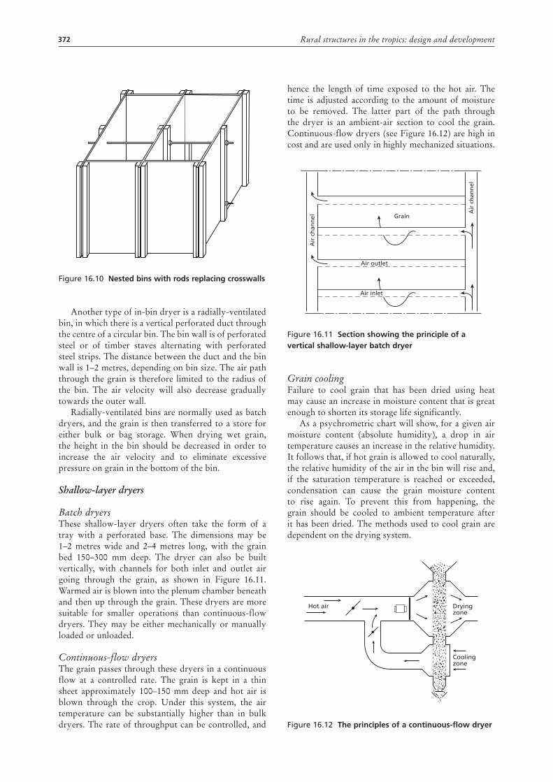
Rectangular bin sizes are limited by the ability of a straight length of wall to resist thrust. The practical limit is around 3 metres and these bins may well be ‘nested’ together (see Figure 16.10). It is possible to omit the crosswall and replace it with tie-rods.
412 m3/kgH2O0025.003.1
=
M2
(M1 − M2)W1W2W1
706 kgH2O100 − 15(21 − 15)10310
100
=×
=
−=−
Total air �ow/hour 4 847 m3/h60
290 824==
372 Rural structures in the tropics: design and development
Figure 16.10 nested bins with rods replacing crosswalls
Another type of in-bin dryer is a radially-ventilated bin, in which there is a vertical perforated duct through the centre of a circular bin. The bin wall is of perforated steel or of timber staves alternating with perforated steel strips. The distance between the duct and the bin wall is 1–2 metres, depending on bin size. The air path through the grain is therefore limited to the radius of the bin. The air velocity will also decrease gradually towards the outer wall.
Radially-ventilated bins are normally used as batch dryers, and the grain is then transferred to a store for either bulk or bag storage. When drying wet grain, the height in the bin should be decreased in order to increase the air velocity and to eliminate excessive pressure on grain in the bottom of the bin.
Shallow-layer dryers
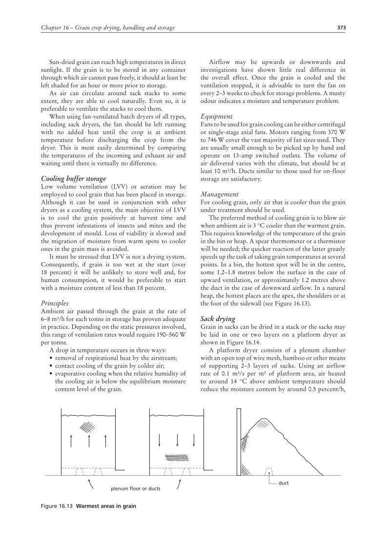
Batch dryersThese shallow-layer dryers often take the form of a tray with a perforated base. The dimensions may be 1–2 metres wide and 2–4 metres long, with the grain bed 150–300 mm deep. The dryer can also be built vertically, with channels for both inlet and outlet air going through the grain, as shown in Figure 16.11. Warmed air is blown into the plenum chamber beneath and then up through the grain. These dryers are more suitable for smaller operations than continuous-flow dryers. They may be either mechanically or manually loaded or unloaded.
Continuous-flow dryersThe grain passes through these dryers in a continuous flow at a controlled rate. The grain is kept in a thin sheet approximately 100–150 mm deep and hot air is blown through the crop. Under this system, the air temperature can be substantially higher than in bulk dryers. The rate of throughput can be controlled, and
hence the length of time exposed to the hot air. The time is adjusted according to the amount of moisture to be removed. The latter part of the path through the dryer is an ambient-air section to cool the grain. Continuous-flow dryers (see Figure 16.12) are high in cost and are used only in highly mechanized situations.
Figure 16.11 Section showing the principle of a vertical shallow-layer batch dryer
Grain coolingFailure to cool grain that has been dried using heat may cause an increase in moisture content that is great enough to shorten its storage life significantly.
As a psychrometric chart will show, for a given air moisture content (absolute humidity), a drop in air temperature causes an increase in the relative humidity. It follows that, if hot grain is allowed to cool naturally, the relative humidity of the air in the bin will rise and, if the saturation temperature is reached or exceeded, condensation can cause the grain moisture content to rise again. To prevent this from happening, the grain should be cooled to ambient temperature after it has been dried. The methods used to cool grain are dependent on the drying system.
Figure 16.12 the principles of a continuous-flow dryer
Air
ch
ann
el
Air
ch
ann
el
Grain
Air outlet
Air inlet
Dryingzone
Hot air
Coolingzone
373Chapter 16 – Grain crop drying, handling and storage
Sun-dried grain can reach high temperatures in direct sunlight. If the grain is to be stored in any container through which air cannot pass freely, it should at least be left shaded for an hour or more prior to storage.
As air can circulate around sack stacks to some extent, they are able to cool naturally. Even so, it is preferable to ventilate the stacks to cool them.
When using fan-ventilated batch dryers of all types, including sack dryers, the fan should be left running with no added heat until the crop is at ambient temperature before discharging the crop from the dryer. This is most easily determined by comparing the temperatures of the incoming and exhaust air and waiting until there is virtually no difference.
Cooling buffer storageLow volume ventilation (LVV) or aeration may be employed to cool grain that has been placed in storage. Although it can be used in conjunction with other dryers as a cooling system, the main objective of LVV is to cool the grain positively at harvest time and thus prevent infestations of insects and mites and the development of mould. Loss of viability is slowed and the migration of moisture from warm spots to cooler ones in the grain mass is avoided.
It must be stressed that LVV is not a drying system. Consequently, if grain is too wet at the start (over 18 percent) it will be unlikely to store well and, for human consumption, it would be preferable to start with a moisture content of less than 18 percent.
PrinciplesAmbient air passed through the grain at the rate of 6–8 m³/h for each tonne in storage has proven adequate in practice. Depending on the static pressures involved, this range of ventilation rates would require 190–560 W per tonne.
A drop in temperature occurs in three ways: • removal of respirational heat by the airstream; • contact cooling of the grain by colder air;• evaporative cooling when the relative humidity of
the cooling air is below the equilibrium moisture content level of the grain.
Airflow may be upwards or downwards and investigations have shown little real difference in the overall effect. Once the grain is cooled and the ventilation stopped, it is advisable to turn the fan on every 2–3 weeks to check for storage problems. A musty odour indicates a moisture and temperature problem.
EquipmentFans to be used for grain cooling can be either centrifugal or single-stage axial fans. Motors ranging from 370 W to 746 W cover the vast majority of fan sizes used. They are usually small enough to be picked up by hand and operate on 13-amp switched outlets. The volume of air delivered varies with the climate, but should be at least 10 m³/h. Ducts similar to those used for on-floor storage are satisfactory.
ManagementFor cooling grain, only air that is cooler than the grain under treatment should be used.
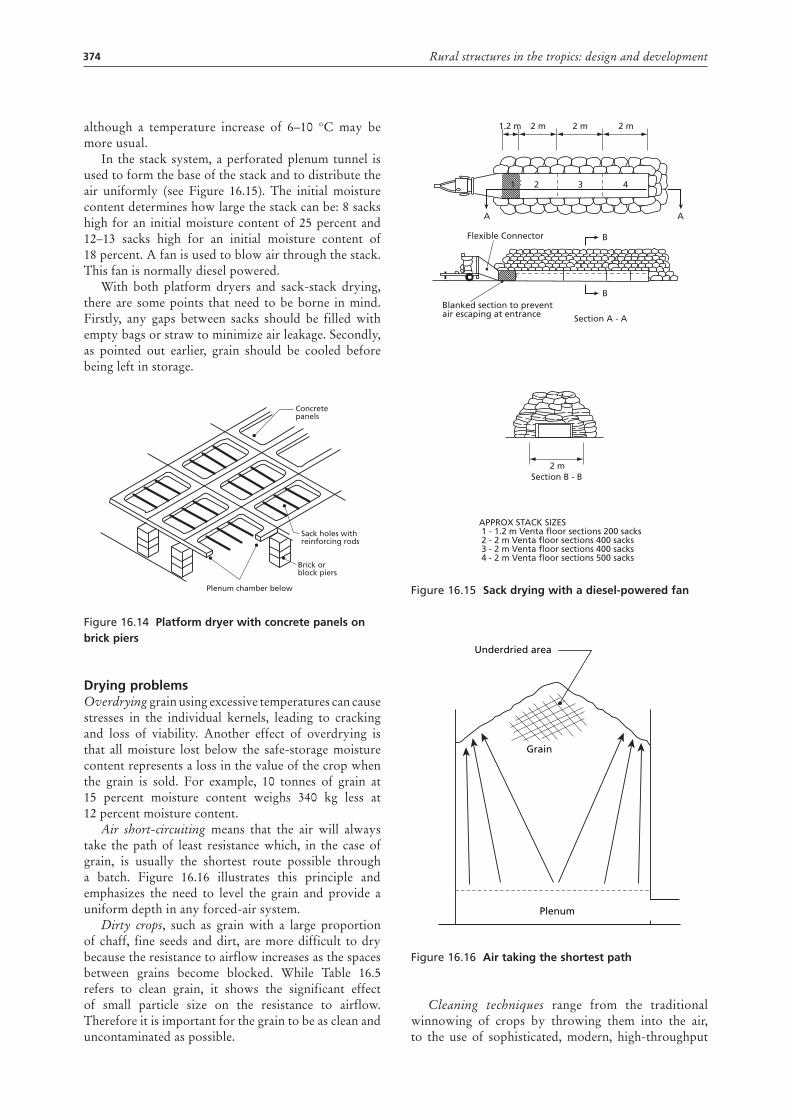
The preferred method of cooling grain is to blow air when ambient air is 3 °C cooler than the warmest grain. This requires knowledge of the temperature of the grain in the bin or heap. A spear thermometer or a thermistor will be needed; the quicker reaction of the latter greatly speeds up the task of taking grain temperatures at several points. In a bin, the hottest spot will be in the centre, some 1.2–1.8 metres below the surface in the case of upward ventilation, or approximately 1.2 metres above the duct in the case of downward airflow. In a natural heap, the hottest places are the apex, the shoulders or at the foot of the sidewall (see Figure 16.13).
Sack dryingGrain in sacks can be dried in a stack or the sacks may be laid in one or two layers on a platform dryer as shown in Figure 16.14.
A platform dryer consists of a plenum chamber with an open top of wire mesh, bamboo or other means of supporting 2–3 layers of sacks. Using an airflow rate of 0.1 m³/s per m² of platform area, air heated to around 14 °C above ambient temperature should reduce the moisture content by around 0.5 percent/h,
Figure 16.13 Warmest areas in grain
ductplenum floor or ducts
374 Rural structures in the tropics: design and development
although a temperature increase of 6–10 °C may be more usual.
In the stack system, a perforated plenum tunnel is used to form the base of the stack and to distribute the air uniformly (see Figure 16.15). The initial moisture content determines how large the stack can be: 8 sacks high for an initial moisture content of 25 percent and 12–13 sacks high for an initial moisture content of 18 percent. A fan is used to blow air through the stack. This fan is normally diesel powered.
With both platform dryers and sack-stack drying, there are some points that need to be borne in mind. Firstly, any gaps between sacks should be filled with empty bags or straw to minimize air leakage. Secondly, as pointed out earlier, grain should be cooled before being left in storage.
Figure 16.14 Platform dryer with concrete panels on brick piers
drying problemsOverdrying grain using excessive temperatures can cause stresses in the individual kernels, leading to cracking and loss of viability. Another effect of overdrying is that all moisture lost below the safe-storage moisture content represents a loss in the value of the crop when the grain is sold. For example, 10 tonnes of grain at 15 percent moisture content weighs 340 kg less at 12 percent moisture content.
Air short-circuiting means that the air will always take the path of least resistance which, in the case of grain, is usually the shortest route possible through a batch. Figure 16.16 illustrates this principle and emphasizes the need to level the grain and provide a uniform depth in any forced-air system.
Dirty crops, such as grain with a large proportion of chaff, fine seeds and dirt, are more difficult to dry because the resistance to airflow increases as the spaces between grains become blocked. While Table 16.5 refers to clean grain, it shows the significant effect of small particle size on the resistance to airflow. Therefore it is important for the grain to be as clean and uncontaminated as possible.
Concretepanels
Sack holes withreinforcing rods
Brick orblock piers
Plenum chamber below
Figure 16.16 air taking the shortest path
Cleaning techniques range from the traditional winnowing of crops by throwing them into the air, to the use of sophisticated, modern, high-throughput
Plenum
Grain
Underdried area
Figure 16.15 Sack drying with a diesel-powered fan
APPROX STACK SIZES 1 - 1.2 m Venta floor sections 200 sacks 2 - 2 m Venta floor sections 400 sacks 3 - 2 m Venta floor sections 400 sacks 4 - 2 m Venta floor sections 500 sacks
Section B - B
Section A - A
Blanked section to preventair escaping at entrance
Flexible Connector
1.2 m 2 m
2 3 41
B
AA
2 m
2 m 2 m
B
375Chapter 16 – Grain crop drying, handling and storage
equipment. The two techniques used on small farms are winnowing and sieving.
Sieving is usually a two-stage operation. The first sieve is just coarse enough to let the grain through while rejecting all larger particles. The second sieve is just fine enough to hold the grain being cleaned, but it passes weed seeds and particles that are smaller than the grain.
Grain may sometimes be given a preliminary cleaning prior to storage to remove the majority of contaminants, and then a second, more thorough, cleaning before sale. This would apply in particular to seed grain.
InstrumentsTemperature, relative humidity, static pressure and airflow measurement are discussed in general in Chapter 13. Here we discuss in more detail some specific points relating to taking such measurements in the case of grain drying and storage.
ThermometersAlthough mercury-in-glass thermometers are fragile and rather slow to react, they are probably the most dependable means of measuring temperature. They may be protected by mounting them in a groove in a wooden or metal probe so that temperatures deep in piles or bins may be checked. Care should be taken to allow several minutes for the temperature to stabilize.
Thermistors and thermocouples are convenient for remote measurements but they are more costly and have adjustment problems.
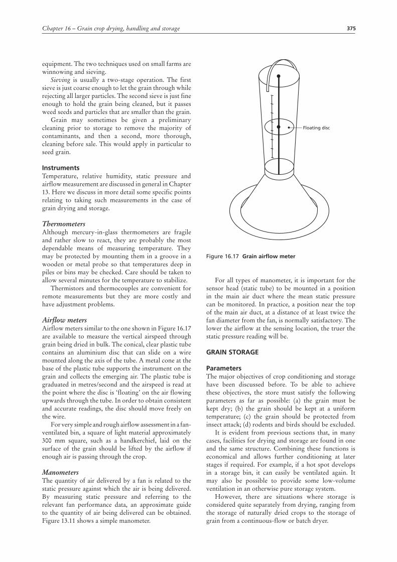
Airflow metersAirflow meters similar to the one shown in Figure 16.17 are available to measure the vertical airspeed through grain being dried in bulk. The conical, clear plastic tube contains an aluminium disc that can slide on a wire mounted along the axis of the tube. A metal cone at the base of the plastic tube supports the instrument on the grain and collects the emerging air. The plastic tube is graduated in metres/second and the airspeed is read at the point where the disc is ‘floating’ on the air flowing upwards through the tube. In order to obtain consistent and accurate readings, the disc should move freely on the wire.
For very simple and rough airflow assessment in a fan-ventilated bin, a square of light material approximately 300 mm square, such as a handkerchief, laid on the surface of the grain should be lifted by the airflow if enough air is passing through the crop.
ManometersThe quantity of air delivered by a fan is related to the static pressure against which the air is being delivered. By measuring static pressure and referring to the relevant fan performance data, an approximate guide to the quantity of air being delivered can be obtained. Figure 13.11 shows a simple manometer.
Figure 16.17 Grain airflow meter
For all types of manometer, it is important for the sensor head (static tube) to be mounted in a position in the main air duct where the mean static pressure can be monitored. In practice, a position near the top of the main air duct, at a distance of at least twice the fan diameter from the fan, is normally satisfactory. The lower the airflow at the sensing location, the truer the static pressure reading will be.
GraIn StoraGE
ParametersThe major objectives of crop conditioning and storage have been discussed before. To be able to achieve these objectives, the store must satisfy the following parameters as far as possible: (a) the grain must be kept dry; (b) the grain should be kept at a uniform temperature; (c) the grain should be protected from insect attack; (d) rodents and birds should be excluded.
It is evident from previous sections that, in many cases, facilities for drying and storage are found in one and the same structure. Combining these functions is economical and allows further conditioning at later stages if required. For example, if a hot spot develops in a storage bin, it can easily be ventilated again. It may also be possible to provide some low-volume ventilation in an otherwise pure storage system.
However, there are situations where storage is considered quite separately from drying, ranging from the storage of naturally dried crops to the storage of grain from a continuous-flow or batch dryer.
Floating disc
376 Rural structures in the tropics: design and development
The size and type of a storage facility is likely to be dictated by:
• total volume of crop/produce to be stored; • the storage requirements for the crop/produce to
be stored; • the unit cost of various types of storage; • the form in which the crop/produce is stored, i.e.
cob maize versus shelled maize, or bagged wheat versus bulk wheat.
The volume of the store required can be estimated from the expected yield and the land area.
A comparison between different forms of storage is normally made by calculating costs per tonne of capacity. The form of storage depends not only on how the crop is harvested, the volume and the way it is delivered to the market, but also on the overall cost. Where drying is a problem, bag storage has the advantage of allowing a higher moisture content than bulk storage. For maize, the requirement for safe storage is a maximum of 15 percent and 12 percent moisture content respectively.
In general terms, the respective advantages and disadvantages of bag and bulk storage are:
Bags Bulk
Flexibility of storage Inflexible storage
Partly mechanizable Mechanizable
Slow handling Rapid handling
Considerable spillage little spillage
low capital costs High capital costs
High operating costs low operating costs
easy inspection Inspection more difficult
Solid-wall bins and silos for bulk storage Solid-wall bins may be anything from a small plastered basket to large steel or concrete silos holding several thousand tons. The traditional bins used by African farmers are small with a capacity of 2–3 tonnes, including gourds, clay pots, mud-plastered baskets raised off the ground and mud-walled silos (‘rumbus’).
Many of these solid-wall bins or silos have limitations, particularly in terms of durability and protection against rodents, insects and moisture from ambient air. Solid-wall bins or silos should be used only in areas where the produce can be dried sufficiently prior to storage. Several attempts have been made to improve on traditional stores to make them more suitable for long-term storage.
Improved traditional binsMany traditional stores perform excellently in their appropriate climatic conditions, and others can be made to do so with minor changes. Efforts should be made to prevent cracking of the surface of the walls and to seal the entrance to the bin. This can be done, for instance,
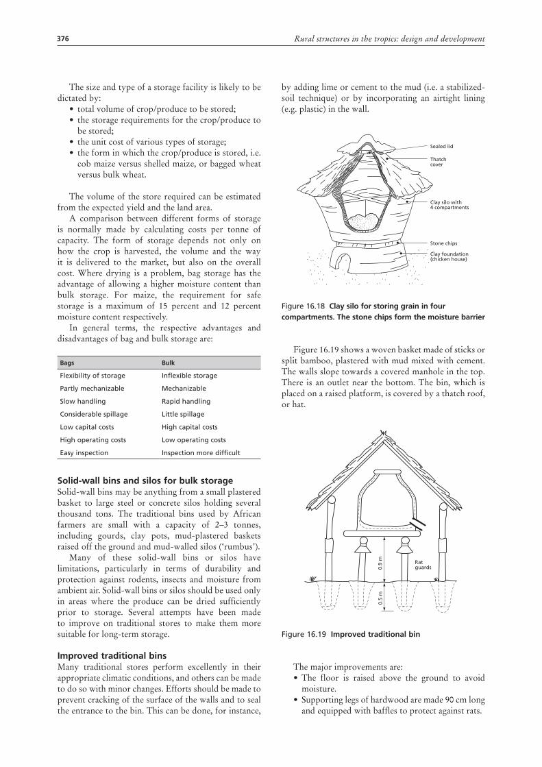
by adding lime or cement to the mud (i.e. a stabilized-soil technique) or by incorporating an airtight lining (e.g. plastic) in the wall.
Figure 16.18 clay silo for storing grain in four compartments. the stone chips form the moisture barrier
Figure 16.19 shows a woven basket made of sticks or split bamboo, plastered with mud mixed with cement. The walls slope towards a covered manhole in the top. There is an outlet near the bottom. The bin, which is placed on a raised platform, is covered by a thatch roof, or hat.
Figure 16.19 Improved traditional bin
The major improvements are:• The floor is raised above the ground to avoid
moisture.• Supporting legs of hardwood are made 90 cm long
and equipped with baffles to protect against rats.
Sealed lid
Thatch cover
Clay silo with 4 compartments
Clay foundation(chicken house)
Stone chips
Ratguards0.
9 m
0.5
m

377Chapter 16 – Grain crop drying, handling and storage
• Instead of mud, the walls may be plastered with cement or mud mixed with cement/lime.
• Inlets and outlets should be made with airtight and lockable covers.
• Thatched roof to protect the bin from rain and strong sun.
• The area around the store should be kept clean.
Underground pitsIn a few countries (e.g. India, parts of Africa and Latin America), it is claimed that underground pits are able to store grain without damage for many years. The pits keep grain cool, and some of them are relatively airtight. However, the grain on top and around the sides often becomes mouldy.
There are several types of pit, most of them flask-shaped and covered with sticks, cow dung and mud, or a large stone embedded in soft mud. The area should be free from termites and relatively dry.
Improvements to the pit may include:• better lining of straw and mat;.• plastic sheets and concrete or ferrocement;• use of plastic bags in the pit;• improved covering:• surface drainage.
Figure 16.20 underground pit
Brick-walled siloBrick-walled silos or bins are suitable for small- and medium-size stores. The need for reinforcement makes them uneconomical when the height exceeds 7–8 metres. The wall may be made of bricks or blocks of mud, stabilized soil, burnt clay, stones or cement. To withstand the pressure from the grain, the wall will need reinforcement commensurate with the size and strength of the building materials.
Reinforcement can be reduced, and even omitted, by building thick, heavy walls (gravity walls). Figure 16.21 shows a silo with gravity walls where the bricks are
Mud or soil
Cow dung
Sticks
Straw lining
placed radially. While no reinforcement is needed for this size, more building material is required.
Walls made of bricks, mud or cement will absorb moisture from the ambient air. In areas with high relative humidity it is therefore necessary to protect the grain by adding a moisture barrier to the silo walls. It will help considerably to bag-wash or plaster the walls on the outside with a mortar of cement–lime–sand (1:1:5) for burnt bricks or cement, and cement–sand–mud (1:2:6) for mud walls. The walls can then be painted with plastic paint or coal tar if better protection is needed.
Figure 16.21 Silo built of bricks laid radially (gravity wall)
An alternative to plastering and painting the silo is to incorporate a lining of plastic sheeting in the middle of the wall, floor and roof to make the container airtight. The Pusa bin is such a structure and has been developed by the Agricultural Research Institute in
200 250
50
250
500
400
100
1 00
0
200 1001 000
378 Rural structures in the tropics: design and development
New Delhi. Originally the bin was rectangular with walls of two layers of brick; the floor and the roof are made of two layers of mud. The system can be used for silos of any shape and, if properly constructed, will give good protection against air and moisture.
Reinforced concrete silosConcrete can take very little tension and needs to be reinforced when used for silos. Small silos suitable for an individual farm may be reinforced with chicken-wire.
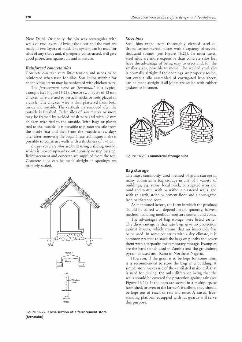
The ferrocement store or ‘ferrumbu’ is a typical example (see Figure 16.22). One or two layers of 12 mm chicken wire are tied to vertical sticks or rods placed in a circle. The chicken wire is then plastered from both inside and outside. The verticals are removed after the outside is finished. Taller silos of 3–4 metres or more may be framed by welded mesh wire and with 12 mm chicken wire tied to the outside. With bags or plastic tied to the outside, it is possible to plaster the silo from the inside first and then from the outside a few days later after removing the bags. These techniques make it possible to construct walls with a thickness of 3–6 cm.
Larger concrete silos are built using a sliding mould, which is moved upwards continuously or step by step. Reinforcement and concrete are supplied from the top. Concrete silos can be made airtight if openings are properly sealed.
Figure 16.22 cross-section of a ferrocement store (ferrumbu)
Metal
Plastic
Chickenwire
50 mm.
WALL
LID
Steel binsSteel bins range from thoroughly cleaned steel oil drums to commercial stores with a capacity of several thousand tonnes (see Figure 16.23). In most cases, steel silos are more expensive than concrete silos but have the advantage of being easy to erect and, for the smaller sizes, possible to move. The welded steel silo is normally airtight if the openings are properly sealed, but even a silo assembled of corrugated iron sheets can be made airtight if all joints are sealed with rubber gaskets or bitumen.
Figure 16.23 commercial storage silos
Bag storageThe most commonly used method of grain storage in many countries is bag storage in any of a variety of buildings, e.g. stone, local brick, corrugated iron and mud and wattle, with or without plastered walls, and with an earth, stone or cement floor and a corrugated iron or thatched roof.
As mentioned before, the form in which the produce should be stored will depend on the quantity, harvest method, handling method, moisture content and costs.
The advantages of bag storage were listed earlier. The disadvantage is that jute bags give no protection against insects, which means that an insecticide has to be used. In some countries with a dry climate, it is common practice to stack the bags on plinths and cover them with a tarpaulin for temporary storage. Examples are the hard stands used in Zambia and the groundnut pyramids used near Kano in Northern Nigeria.
However, if the grain is to be kept for some time, it is recommended to store the bags in a building. A simple store makes use of the ventilated maize crib that is used for drying, the only difference being that the walls should be covered for protection against rain (see Figure 16.24). If the bags are stored in a multipurpose farm shed, or even in the farmer’s dwelling, they should be kept out of reach of rats and mice. A raised, free-standing platform equipped with rat guards will serve this purpose.
379Chapter 16 – Grain crop drying, handling and storage
Figure 16.24 Ventilated maize crib used for storing shelled maize in bags
For larger quantities, a special building is recommended. Figure 16.25 shows a small block-built bag store (20 m²) with the capacity to store approximately 15 tonnes of cereals.
Thatch-coveredwall
Rat-guard
Figure 16.25 Small block-built bag store
Whatever the size of the bag store, the floor should be made of good quality concrete, the door should fit tightly to protect against rodents, and ventilation openings should be screened to keep out birds. The gaps between the wall and the roofing sheets must be closed using a material such as cement.
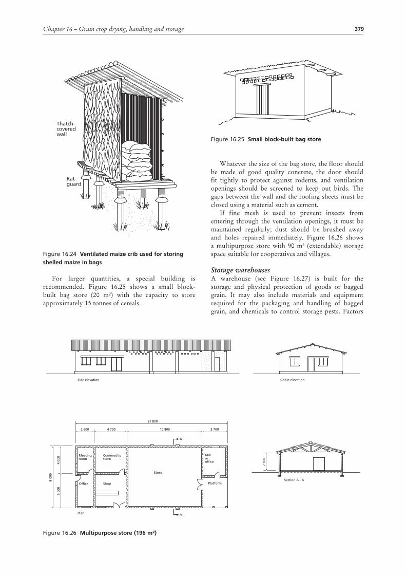
If fine mesh is used to prevent insects from entering through the ventilation openings, it must be maintained regularly; dust should be brushed away and holes repaired immediately. Figure 16.26 shows a multipurpose store with 90 m² (extendable) storage space suitable for cooperatives and villages.
Storage warehousesA warehouse (see Figure 16.27) is built for the storage and physical protection of goods or bagged grain. It may also include materials and equipment required for the packaging and handling of bagged grain, and chemicals to control storage pests. Factors
Figure 16.26 Multipurpose store (196 m²)
Meetingroom
Commoditystore
Shop
Store
Milloroffice
PlatformOffice
Plan
Side elevation Gable elevation
Section A - A
4 00
05
000
9 00
0
10 800
A
4 700 3 7002 600
21 800
A
2 50
0
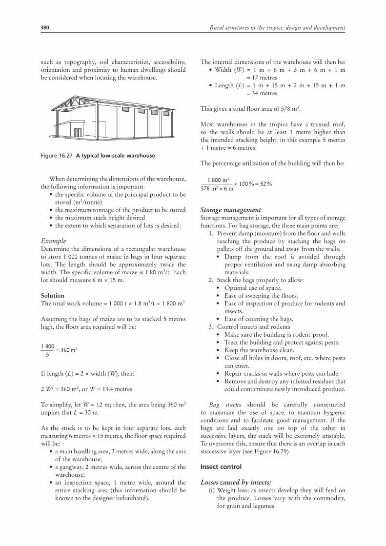
380 Rural structures in the tropics: design and development
such as topography, soil characteristics, accessibility, orientation and proximity to human dwellings should be considered when locating the warehouse.
Figure 16.27 a typical low-scale warehouse
When determining the dimensions of the warehouse, the following information is important:
• the specific volume of the principal product to be stored (m3/tonne)
• the maximum tonnage of the product to be stored• the maximum stack height desired• the extent to which separation of lots is desired.
ExampleDetermine the dimensions of a rectangular warehouse to store 1 000 tonnes of maize in bags in four separate lots. The length should be approximately twice the width. The specific volume of maize is 1.80 m3/t. Each lot should measure 6 m × 15 m.
SolutionThe total stock volume = 1 000 t × 1.8 m3/t = 1 800 m3
Assuming the bags of maize are to be stacked 5 metres high, the floor area required will be:
If length (L) = 2 × width (W), then:
2 W2 = 360 m2, or W = 13.4 metres
To simplify, let W = 12 m; then, the area being 360 m2 implies that L = 30 m.
As the stock is to be kept in four separate lots, each measuring 6 metres × 15 metres, the floor space required will be:
• a main handling area, 3 metres wide, along the axis of the warehouse;
• a gangway, 2 metres wide, across the centre of the warehouse;
• an inspection space, 1 metre wide, around the entire stacking area (this information should be known to the designer beforehand).
3605
1 800m2=
%52%1006 m578 m2
1 800 m3
=××
The internal dimensions of the warehouse will then be:• Width (W) = 1 m + 6 m + 3 m + 6 m + 1 m
= 17 metres• Length (L) = 1 m + 15 m + 2 m + 15 m + 1 m
= 34 metres
This gives a total floor area of 578 m².
Most warehouses in the tropics have a trussed roof, so the walls should be at least 1 metre higher than the intended stacking height: in this example 5 metres + 1 metre = 6 metres.
The percentage utilization of the building will then be:
Storage managementStorage management is important for all types of storage functions. For bag storage, the three main points are:
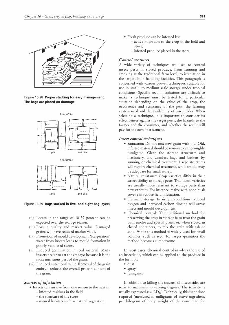
1. Prevent damp (moisture) from the floor and walls reaching the produce by stacking the bags on pallets off the ground and away from the walls.• Damp from the roof is avoided through
proper ventilation and using damp absorbing materials.
2. Stack the bags properly to allow:• Optimal use of space.• Ease of sweeping the floors.• Ease of inspection of produce for rodents and
insects.• Ease of counting the bags.
3. Control insects and rodents• Make sure the building is rodent-proof.• Treat the building and protect against pests.• Keep the warehouse clean.• Close all holes in doors, roof, etc. where pests
can enter.• Repair cracks in walls where pests can hide.• Remove and destroy any infested residues that
could contaminate newly introduced produce.
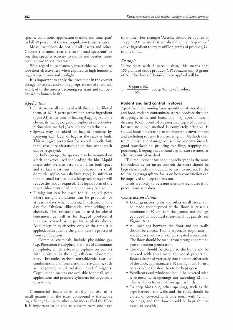
Bag stacks should be carefully constructed to maximize the use of space, to maintain hygienic conditions and to facilitate good management. If the bags are laid exactly one on top of the other in successive layers, the stack will be extremely unstable. To overcome this, ensure that there is an overlap in each successive layer (see Figure 16.29).
Insect control
Losses caused by insects: (i) Weight loss: as insects develop they will feed on
the produce. Losses vary with the commodity, for grain and legumes.
3605
1 800m2=
%52%1006 m578 m2
1 800 m3
=××
381Chapter 16 – Grain crop drying, handling and storage
Figure 16.28 Proper stacking for easy management. the bags are placed on dunnage
Figure 16.29 Bags stacked in five- and eight-bag layers
(ii) Losses in the range of 10–30 percent can be expected over the storage season.
(iii) Loss in quality and market value. Damaged grains will have reduced market value.
(iv) Promotion of mould development. ‘Respiration’ water from insects leads to mould formation in poorly ventilated stores.
(v) Reduced germination in seed material. Many insects prefer to eat the embryo because it is the most nutritious part of the grain.
(vi) Reduced nutritional value. Removal of the grain embryo reduces the overall protein content of the grain.
Sources of infestation• Insects can survive from one season to the next in:
– infested residues in the field – the structure of the store– natural habitats such as natural vegetation.
2nd pile
2nd pile
1st pile
1st pile
5 sacks/pile
8 sacks/pile
• Fresh produce can be infested by: – active migration to the crop in the field and store;– infested produce placed in the store.
Control measuresA wide variety of techniques are used to control insect pests in stored produce, from sunning and smoking at the traditional farm level, to irradiation in the largest bulk-handling facilities. This paragraph is concerned with various proven techniques, suitable for use in small- to medium-scale storage under tropical conditions. Specific recommendations are difficult to make; a technique must be tested for a particular situation depending on the value of the crop, the occurrence and resistance of the pest, the farming system used and the availability of insecticides. When selecting a technique, it is important to consider its effectiveness against the target pests, the hazards to the farmer and the consumer, and whether the result will pay for the cost of treatment.
Insect control techniques • Sanitation: Do not mix new grain with old. Old,
infested material should be removed or thoroughly fumigated. Clean the storage structures and machinery, and disinfect bags and baskets by sunning or chemical treatment. Large structures will require chemical treatment, while smoke may be adequate for small stores.
• Natural resistance: Crop varieties differ in their susceptibility to storage pests. Traditional varieties are usually more resistant to storage pests than new varieties. For instance, maize with good husk cover can reduce field infestation.
• Hermetic storage: In airtight conditions, reduced oxygen and increased carbon dioxide will arrest insect and mould development.
• Chemical control: The traditional method for preserving the crop in storage is to treat the grain with smoke and special plants or, when stored in closed containers, to mix the grain with ash or sand. While this method is widely used for small volumes, such as seed, for larger quantities the method becomes cumbersome.
In most cases, chemical control involves the use of an insecticide, which can be applied to the produce in the form of:
• dust• spray• fumigants
In addition to killing the insects, all insecticides are toxic to mammals to varying degrees. The toxicity is usually expressed as a ‘LD50’. Technically, this is the dose required (measured in milligrams of active ingredient per kilogram of body weight of the consumer, for
382 Rural structures in the tropics: design and development
specific conditions, application method and time span) to kill 50 percent of the test population (usually rats).
Most insecticides do not kill all insects and mites. Choose a chemical that is either ‘broad spectrum’ or one that specifies toxicity to moths and beetles; mites may require special treatment.
With regard to persistence, insecticides will tend to lose their effectiveness when exposed to high humidity, high temperatures and sunlight.
It is important to apply the insecticide in the correct dosage. Excessive and/or inappropriate use of chemicals will lead to the insects becoming resistant and can be a hazard to human health.
Application• Dusts are usually admixed with the grain in diluted
form, at 10–15 parts per million active ingredient (ppm AI) at the time of loading/bagging. Suitable chemicals include organophosphorus insecticides, pirimephos-methyl (Actellic) and pyrethroids.
• Sprays may be added to bagged produce by spraying each layer of bags as the stack is built. This will give protection for several months but, in the case of reinfestation, the surface of the stack can be resprayed. For bulk storage, the sprayer may be mounted on a belt conveyer used for loading the bin. Liquid insecticides are also very suitable for both space and surface treatment. For application, a small domestic applicator (shelltox type) is sufficient for the small farmer, but a knapsack sprayer will reduce the labour required. The liquid form of the insecticides mentioned in point 1 may be used.
• Fumigation can be used for killing all pests where airtight conditions can be provided for at least 3 days when applying Phostoxin, or one day for Ethylene dibromide, after adding the chemical. The treatment can be used for closed containers, as well as for bagged produce, if they are covered by tarpaulin or plastic sheets. As fumigation is effective only at the time it is applied, subsequently the grain must be protected from reinfestation.
Common chemicals include phosphine gas (e.g. Phostoxin is supplied in tablets of aluminium phosphide, which release phosphine on contact with moisture in the air); ethylene dibromide, metyl bromide, carbon tetrachloride (various combinations and formulations are available, such as Trogocide) – all volatile liquid fumigants. Capsules and sachets are available for small-scale applications and pressure cylinders for large-scale operations.
Commercial insecticides usually consist of a small quantity of the toxic compound – the active ingredient (AI) – with other substances called the filler. It is important to be able to convert from one basis
to another. For example ‘Actellic should be applied at 15 ppm AI’ means that we should apply 15 grams of active ingredient to every million grams of produce, i.e. to one tonne.
ExampleIf we start with 5 percent dust, this means that 100 grams of crude product (CP) contains only 5 grams of AI. The dose of chemical to be applied will be:
rodent and bird control in storesApart from consuming large quantities of stored grain and food, rodents contaminate stored produce through droppings, urine and hairs, and may spread human diseases. Rodent control requires an integrated approach because no single method is completely effective. It should focus on creating an unfavourable environment and excluding rodents from stored grain. Methods used to minimize the damage caused by rodents include good housekeeping, proofing, repelling, trapping and poisoning. Keeping a cat around a grain store is another effective control method.
The requirement for good housekeeping is the same for rodents as for insect control; the store should be kept clean inside and out and be easy to inspect. In the following paragraph we focus on how construction can be improved to keep rodents out.
Birds are likely to be a nuisance in warehouses if no precautions are taken.
Construction details • Local granaries, cribs and other small stores can
be made rodent-proof if the floor is raised a minimum of 90 cm from the ground and the legs equipped with conical sheet-metal rat guards (see Figure 16.5).
• All openings between the floor and the walls should be closed. This is especially important in warehouses with walls of corrugated iron sheets. The floor should be made from strong concrete to prevent rodent penetration.
• The door should fit closely to the frame and be covered with sheet metal for added protection. Boards dropped vertically into slots on either side of the door, approximately 50 cm high, will form a barrier while the door has to be kept open.
• Ventilators and windows should be covered with wire mesh ,with openings not exceeding 12 mm. This will also form a barrier against birds.
• To keep birds out, other openings, such as the gaps between the walls and the roof, should be closed or covered with wire mesh with 12 mm openings, and the door should be kept shut as much as possible.
q 300 gr/tonne of produce%5
10015 ppm=
×=
383Chapter 16 – Grain crop drying, handling and storage
• Ideally, the proofing of large central storage depots should be considered during the planning stage; this allows it to be incorporated at very low cost into the construction of each building.
• In many cases, existing stores can be protected by a rodent-proof fence at least 90 mm high. This should be constructed of small-gauge wire netting, topped by a horizontal metal sheet, which should completely encircle the store. The bottom of the fence should be buried to a depth of at least 30 cm.
Using the protective measures described above, it is possible to reduce, and even eliminate, the rodent problem if the measures are properly maintained.
Storage management, hygiene and safety
Condensation and moisture movement If bins, especially silos, are exposed to direct sunlight, or if the grain inside the silo is warmer than the external air, convection currents can form. This leads to the moist air being carried through the grain and, where it meets a cooler surface, such as the silo wall, the moisture will condense and dampen the grain in the immediate vicinity. Clearly this can be a major problem with grain stored in steel silos in hot climates,
particularly in areas where the sky is clear during both day and night. A clear sky results in high daytime temperatures and cool nights.
For small silos, the problem can be reduced by covering the silo with a roof, or hat, to prevent the sun from heating the surface. For larger silos, other solutions have to be found, either by ventilating the grain in the store or by moving the grain from one silo/cell to another. This will mix the grain enough to even out the moisture content. If the moisture content is too high, the grain will need to be run through a dryer.
HygieneInsect and rodent control was discussed earlier in the section on bag storage. However, for all types and sizes of grain store, cleaning will have to be carried out when the store is empty. If the insect population is building up, the entire store may have to be fumigated or sprayed.
SafetyDust is stirred up when grain is handled. Inhalation can cause respiratory problems, especially exposure to slightly mouldy grain. Breathing filters should be used. As grain dust is explosive, it is important to enforce a no-smoking rule and ensure that all light bulbs and
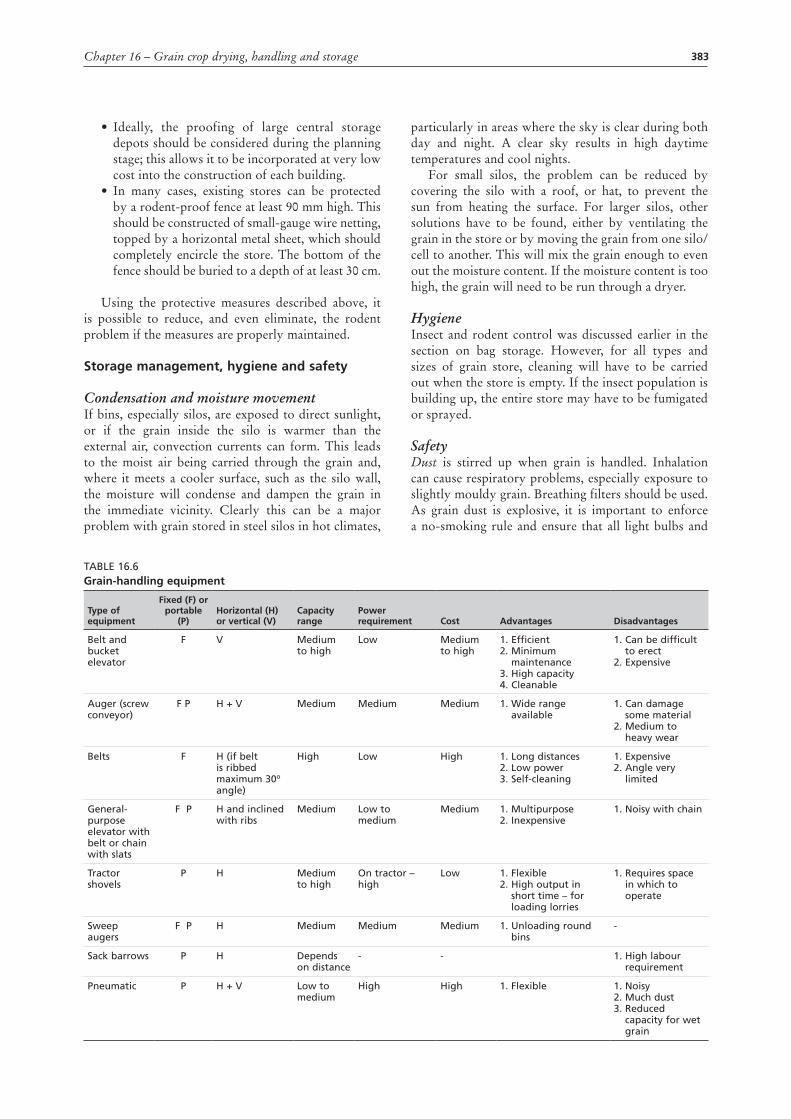
Table 16.6Grain-handling equipment
type of equipment
Fixed (F) or portable
(P)Horizontal (H) or vertical (V)
capacity range
Power requirement cost advantages disadvantages
belt and bucket elevator
F V Medium to high
low Medium to high
1. efficient2. Minimum
maintenance3. High capacity4. Cleanable
1. Can be difficult to erect
2. expensive
auger (screw conveyor)
F P H + V Medium Medium Medium 1. Wide range available
1. Can damage some material
2. Medium to heavy wear
belts F H (if belt is ribbed maximum 30o
angle)
High low High 1. long distances2. low power3. Self-cleaning
1. expensive2. angle very
limited
General- purpose elevator with belt or chain with slats
F P H and inclined with ribs
Medium low to medium
Medium 1. Multipurpose2. Inexpensive
1. Noisy with chain
Tractor shovels
P H Medium to high
On tractor – high
low 1. Flexible2. High output in
short time – for loading lorries
1. Requires space in which to operate
Sweep augers
F P H Medium Medium Medium 1. Unloading round bins
-
Sack barrows P H Depends on distance
- - 1. High labour requirement
Pneumatic P H + V low to medium
High High 1. Flexible 1. Noisy2. Much dust3. Reduced
capacity for wet grain
384 Rural structures in the tropics: design and development
electrical equipment are shielded. Good ventilation is recommended.
Falls: All catwalks where a person could fall more than 150 cm should have guard rails 100 cm high, with 15 cm toeboards.
Crusts can form in damp grain beneath which the grain has run out. Walking on bridged grain can cause failure of the crust, resulting in burial and suffocation.
Machinery: All moving parts should have guards fitted and all wiring should be maintained regularly.
Grain flowing out of a container tends to form a funnel at the centre. This highly unstable surface can suck a person in within seconds.
GraIn-HandlInG EquIPMEntThere is a wide variety of grain-handling equipment available on the market, and Table 16.6 attempts to categorize their ability to move grain.
Belt-and-bucket elevatorsA flat belt is carried between a crowned pulley at the top and bottom of the casing. Small buckets or scoops are fixed to the belts at regular intervals and these carry the grain from the elevator bottom to the top. The capacity depends upon the width of the buckets, the spacing and the belt speed. Elevators up to 20 metres in height and with a capacity of 50 tonnes per hour are available.
auger (screw conveyors)Auger elevators are reasonable in cost, comparatively light in weight, and dependable in their operation. They are available in a wide range of lengths and capacities and are usually powered by an electric motor. Long augers may be mounted on wheels for easy transport. The angle of operation is adjustable but the capacity declines as the auger is raised (see Table 16.7). High moisture content also reduces the capacity.
Table 16.7Example of auger capacity and power requirements per 3-metre length of auger (diameter 150 mm)
Moisture content (percent)
angle of elevation
0° t/hr kW
22.5° t/hr kW
45° t/hr kW
67.5° t/hr kW
90° t/hr kW
14 27 0.42 25 0.61 21 0.64 17 0.62 13 0.52
25 17 1.32 15 1.40 13 1.33 10 1.08 7 0.52
Note: auger speed 400 rpm; power requirement is directly proportional to the auger length.
Flat-belt conveyorsIn practice flat-belt conveyors are used horizontally, although up to 15° inclination is possible. With ribs, the angle can be increased to 30°. The capacity is high, and grain can be loaded or unloaded anywhere along the belt. It does not cause any damage to the crop and raises little dust.
chain-and-slat conveyorsThese consist of a chain carrying traverse slats that drag the grain along a metal or wooden trough. Slat widths up to 300 mm, spaced 150–300 mm apart, and chain speeds of 10–77 cm/s are used to give an output of up to 30 tonnes per hour. Small models have no support frame and can be carried by two people.
Sack elevatorsThis may be a continuous belt with ribs or a chain conveyor with slats.
dumping pitsAn effective system for receiving grain must be used if high capacity is to be achieved when using tractors and trailers to take grain to the store. Ideally, it should be possible to dump a trailer load and pull away within minutes. Such a reception facility will normally be associated with an elevator to raise grain for conditioning or storage.
Reception pit with an elevatorA pit lined with concrete, wood or steel with an inverted pyramid or V-shaped bottom is built in the ground (see Figure 16.30).
Figure 16.30 dump pit with an auger moving the grain to the elevator
The crop is dumped from a trailer into the reception pit, from where it flows by gravity, or with the help of an auger, into a second pit containing the bottom end of an elevator. Having a ‘run-over’ pit saves much time as it avoids the need for farm transport to reverse to the tipping pit. A run-over pit requires a safety grid, which must be strong enough to carry a loaded trailer.
Elevator
Inspectionpit
Auger
A
APLAN
A - A
min45°
Concrete slab
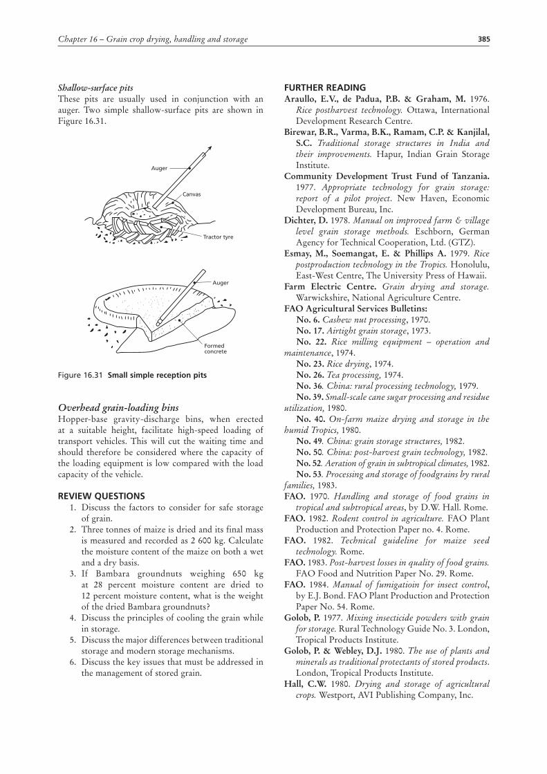
385Chapter 16 – Grain crop drying, handling and storage
Shallow-surface pitsThese pits are usually used in conjunction with an auger. Two simple shallow-surface pits are shown in Figure 16.31.
Figure 16.31 Small simple reception pits
Overhead grain-loading binsHopper-base gravity-discharge bins, when erected at a suitable height, facilitate high-speed loading of transport vehicles. This will cut the waiting time and should therefore be considered where the capacity of the loading equipment is low compared with the load capacity of the vehicle.
rEVIEW quEStIonS1. Discuss the factors to consider for safe storage
of grain.2. Three tonnes of maize is dried and its final mass
is measured and recorded as 2 600 kg. Calculate the moisture content of the maize on both a wet and a dry basis.
3. If Bambara groundnuts weighing 650 kg at 28 percent moisture content are dried to 12 percent moisture content, what is the weight of the dried Bambara groundnuts?
4. Discuss the principles of cooling the grain while in storage.
5. Discuss the major differences between traditional storage and modern storage mechanisms.
6. Discuss the key issues that must be addressed in the management of stored grain.
Auger
Auger
Canvas
Tractor tyre
Formedconcrete
FurtHEr rEadInGAraullo, E.V., de Padua, P.B. & Graham, M. 1976.
Rice postharvest technology. Ottawa, International Development Research Centre.
Birewar, B.R., Varma, B.K., Ramam, C.P. & Kanjilal, S.C. Traditional storage structures in India and their improvements. Hapur, Indian Grain Storage Institute.
Community Development Trust Fund of Tanzania. 1977. Appropriate technology for grain storage: report of a pilot project. New Haven, Economic Development Bureau, Inc.
Dichter, D. 1978. Manual on improved farm & village level grain storage methods. Eschborn, German Agency for Technical Cooperation, Ltd. (GTZ).
Esmay, M., Soemangat, E. & Phillips A. 1979. Rice postproduction technology in the Tropics. Honolulu, East-West Centre, The University Press of Hawaii.
Farm Electric Centre. Grain drying and storage. Warwickshire, National Agriculture Centre.
FAO Agricultural Services Bulletins:No. 6. Cashew nut processing, 1970.No. 17. Airtight grain storage, 1973.No. 22. Rice milling equipment – operation and
maintenance, 1974.No. 23. Rice drying, 1974.No. 26. Tea processing, 1974.No. 36. China: rural processing technology, 1979.No. 39. Small-scale cane sugar processing and residue
utilization, 1980.No. 40. On-farm maize drying and storage in the
humid Tropics, 1980.No. 49. China: grain storage structures, 1982.No. 50. China: post-harvest grain technology, 1982.No. 52. Aeration of grain in subtropical climates, 1982.No. 53. Processing and storage of foodgrains by rural
families, 1983.FAO. 1970. Handling and storage of food grains in
tropical and subtropical areas, by D.W. Hall. Rome.FAO. 1982. Rodent control in agriculture. FAO Plant
Production and Protection Paper no. 4. Rome.FAO. 1982. Technical guideline for maize seed
technology. Rome.FAO. 1983. Post-harvest losses in quality of food grains.
FAO Food and Nutrition Paper No. 29. Rome.FAO. 1984. Manual of fumigatioin for insect control,
by E.J. Bond. FAO Plant Production and Protection Paper No. 54. Rome.
Golob, P. 1977. Mixing insecticide powders with grain for storage. Rural Technology Guide No. 3. London, Tropical Products Institute.
Golob, P. & Webley, D.J. 1980. The use of plants and minerals as traditional protectants of stored products. London, Tropical Products Institute.
Hall, C.W. 1980. Drying and storage of agricultural crops. Westport, AVI Publishing Company, Inc.
386 Rural structures in the tropics: design and development
Harris, K.L. & Lindblad, C.J. 1978. Postharvest grain loss assessment methods for the evaluation of postharvest losses. American Association of Cereal Chemists.
International Ferrocement Information Centre. 1979. International Ferrocement Information Centre Do It Yourself Series, No. 1. Bangkok.
Lindblad, C. & Druben, L. 1976. Small farm grain storage: appropriate technologies for development. Mt. Rainer, Action/Peace Corps and Volunteers in Technical Assistance.
Nilson, C., Pahlstorp, S. & Henriksson, R. 1982. Ferrocement stores for bagged grain and other purposes. Report 24. Lund, Swedish University of Agricultural Sciences, Department of Farm Buildings.
Nilson, C., Pahlstorp, S. & Henriksson, R. 1984. Ferrocement stores for bagged grain and other purposes. Report 36. Lund, Swedish University of Agricultural Sciences, Department of Farm Buildings.
Nygaard-Pedersen, G. 1982. Solid-walled grain bins. Lusaka, Ministry of Agriculture and Water Development.
Rural Structures Unit. 1984. The improved maize crib: a guide to small farm grain storage. Volume 1: Theoretical background. Volume 11: Description and drawings. Nakuru, Ministry of Agriculture.
Siegel, A. & Fawcett, P. 1976. Food legume processing and utilization, with special emphasis on application in developing countries. Ottawa, International Development Research Centre.
Tropical Development and Research Institute. Tropical stored products information. The Journal of the Storage Department of the Tropical Development and Research Institute (formerly Tropical Products Institute).
World Food Programme. 1979. Food storage: handbook on good storage practice, Rome.
387
Chapter 17
Rural roads
IntRoductIonRural roads play a critical role in agricultural and rural development in general. While most roads pass through rural areas, the roads considered in this section are those that link farms, villages and rural markets; trunk roads and district roads are beyond the scope of this book. Inadequate rural road infrastructure, in particular what is often called the last mile (i.e. the section of the road nearest to the farmstead), is regarded as one of the greatest constraints on improving agricultural productivity, especially in tropical regions. These rural roads provide critical links between the farms and rural households and the input and output markets, thereby increasing the profitability of any investments in rural areas.
In many countries, rural roads fall under the jurisdiction of the local authorities. In this regard, farmers or their associations, the village, ward and subdistrict authorities have inordinate power over decisions on where to construct such rural roads, the levels of capital investment and maintenance resources. The cost of construction can be quite high and adverse weather conditions (e.g. floods) result in high maintenance costs. Building local capacity to construct and maintain such roads therefore contributes significantly to lowering costs.
Rural access roads range from the simplest earth roads to bituminous surfaced roads. In most cases, earth roads are the only ones that can be justified for access to rural homes and farmsteads. These roads, designated in many countries as unimproved earth roads, are generally suitable only for light traffic: up to a few dozen vehicles per day. In the wet season, especially in high rainfall areas, they often become impassable. Although, in most cases, there is no need for structural design for such unimproved roads, there are some principles which, if followed, will result in a reasonably good road that justifies the modest investment. The aim of this chapter is to explain some of these principles.
Road locationWhile some roads are constructed entirely from scratch, more often than not a sequence of communication routes evolves as the area develops. This may start with a footpath, which later turns into a track and, through gradual improvement, becomes an earth road that is passable for most of the year. It is therefore advantageous to choose a road line at an early stage in the planning process that will allow for gradual
improvement of the road without having to make long and costly diversions.
A survey to determine the best location for a road line starts by identifying areas through which the road must pass (for example, a gap between hills), the best location for a river crossing, and the points to be linked by the road. Places to be avoided include soft ground, steep slopes and areas with big rocks. For large-scale road projects, the terrain is viewed from aerial photographs, but for smaller projects this is too costly and an overview of the proposed road line must be obtained from adjacent hills. Although such an overview provides valuable information on natural drainage, it should always be supplemented by a detailed examination on foot.
Once the points through which the road must pass have been established, the road line is laid out to run as directly as possible between these points. Wherever possible, roads should be located on sandy soils in well-drained locations, avoiding wet and low-lying areas prone to flooding. To take full advantage of natural drainage, it makes sense to locate the road along the backbone of a watershed if it runs roughly parallel to the road line. This will ensure the best possible drainage away from the road, and expensive bridge, culvert or drift construction can be avoided. However, an attempt to avoid all the difficult spots may result in a longer road, and the additional cost of construction and maintenance should always be weighed against the cost of a road built in a more direct line.
GradientsA steep gradient not only slows down traffic and increases the load on vehicles, it also complicates road construction and increases the cost because care must be taken to avoid erosion from storm water flowing on and alongside the road. A gradient can be expressed in three ways:
• units of rise relative to units of horizontal distance (e.g. 1:40);
• percentage (e.g. 2.5 percent); • angle to the horizontal (e.g. 1° 26‘).
Although the recommended gradient standards for unimproved roads differ between countries, generally, for roads used mainly by motor vehicles, the gradient should not exceed 1 in 17 in flat or rolling terrain, 1 in 13 in hilly terrain, or 1 in 11 in mountainous
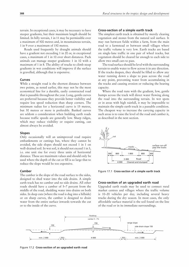
388 Rural structures in the tropics: design and development
terrain. In exceptional cases, it may be necessary to have steeper gradients, but their maximum length should be limited. In hilly terrain, 1 in 11 may be permissible over a maximum of 500 metres and, in mountainous terrain, 1 in 9 over a maximum of 150 metres.
Roads used frequently by draught animals should have a gradient not exceeding 1 in 20 or, in exceptional cases, a maximum of 1 in 10 over short distances. Pack animals can manage steeper gradients: 1 in 10 with a maximum of 1 in 8. The ability of trucks to climb steep gradients in wet conditions will improve if the surface is gravelled, although that is expensive.
curvesWhile a straight road is the shortest distance between two points, as noted earlier, this may not be the most economical line for a durable, easily constructed road that is passable throughout the year. Long, gentle curves are preferred because they provide better visibility and require less speed reduction than sharp corners. The minimum radius for a horizontal curve is 15 metres, but 30 metres or more is preferable. Banked curves are seldom a consideration when building earth roads because traffic speeds are generally low. Sharp ridges, which may reduce visibility or require cutting, can almost always be avoided.
SlopesOnly occasionally will an unimproved road require embankments or cuttings but, where they cannot be avoided, the side slopes should not exceed 1 in 1 on well-drained soil. In wet soil, it should not exceed 1 in 3, i.e. one unit rise for every three units of horizontal distance. These are maximum values and should only be used where the depth of the cut or fill is so large that to reduce the slope would be too expensive.
camberThe camber is the slope of the road surface to the sides, designed to shed water into the side drains. A simple earth track has no camber and no side drains. All other roads should have a camber of 5–7 percent from the middle of the road, shedding water into drains on both sides. In deep cuts (where the road is dug into a hillside) or on sharp curves, the camber is designed to drain water from the entire surface inwards towards the cut or to the inside of the curve.
cross-section of a simple earth trackThe simplest earth track is obtained by merely clearing vegetation and stones from the natural soil surface. It may run between fields within a farm, from the main road to a farmstead or between small villages where the traffic volume is very low. Earth tracks are based on single-lane traffic in one pair of wheel tracks, but vegetation should be cleared far enough to each side to allow two small cars to pass.
The road surface should be level with the surrounding terrain to enable water to flow across it in any direction. If the tracks deepen, they should be filled to allow any water running down a slope to pass across the road at any point, preventing water from accumulating in the tracks and causing erosion or reducing the bearing capacity.
Where the road runs with the gradient, low, gentle humps across the track will direct water flowing along the road into the surrounding terrain. In wet spots or in areas with high rainfall, it may be impossible to maintain the simple earth track in a passable condition. The cheapest way to increase the carrying capacity in such areas is to raise the level of the road and camber it, as described in the next section.
Figure 17.1 cross-section of a simple earth track
cross-section of an upgraded earth roadUpgraded earth roads may be used to connect rural market centres and villages where the traffic volume is 10–20 vehicles per day, including several heavy trucks during the dry season. In most cases, the only affordable surface material is the soil found on the line of the road or in its immediate surroundings.
cut
tracks
Cleared and stumped
Road
300 300800800 1 800
surface run-offpast the tracks
4 0003 400
Figure 17.2 cross-section of an upgraded earth road
150150
min. 2 000 350 4 000 350 min. 2 000
verge slope
side drain slope 150
Roadway
camber 5 - 7%
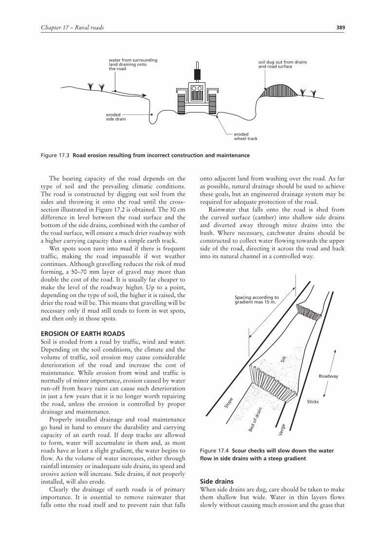
389Chapter 17 – Rural roads
The bearing capacity of the road depends on the type of soil and the prevailing climatic conditions. The road is constructed by digging out soil from the sides and throwing it onto the road until the cross-section illustrated in Figure 17.2 is obtained. The 30 cm difference in level between the road surface and the bottom of the side drains, combined with the camber of the road surface, will ensure a much drier roadway with a higher carrying capacity than a simple earth track.
Wet spots soon turn into mud if there is frequent traffic, making the road impassable if wet weather continues. Although gravelling reduces the risk of mud forming, a 50–70 mm layer of gravel may more than double the cost of the road. It is usually far cheaper to make the level of the roadway higher. Up to a point, depending on the type of soil, the higher it is raised, the drier the road will be. This means that gravelling will be necessary only if mud still tends to form in wet spots, and then only in those spots.
ERoSIon of EaRth RoadSSoil is eroded from a road by traffic, wind and water. Depending on the soil conditions, the climate and the volume of traffic, soil erosion may cause considerable deterioration of the road and increase the cost of maintenance. While erosion from wind and traffic is normally of minor importance, erosion caused by water run-off from heavy rains can cause such deterioration in just a few years that it is no longer worth repairing the road, unless the erosion is controlled by proper drainage and maintenance.
Properly installed drainage and road maintenance go hand in hand to ensure the durability and carrying capacity of an earth road. If deep tracks are allowed to form, water will accumulate in them and, as most roads have at least a slight gradient, the water begins to flow. As the volume of water increases, either through rainfall intensity or inadequate side drains, its speed and erosive action will increase. Side drains, if not properly installed, will also erode.
Clearly the drainage of earth roads is of primary importance. It is essential to remove rainwater that falls onto the road itself and to prevent rain that falls
onto adjacent land from washing over the road. As far as possible, natural drainage should be used to achieve these goals, but an engineered drainage system may be required for adequate protection of the road.
Rainwater that falls onto the road is shed from the curved surface (camber) into shallow side drains and diverted away through mitre drains into the bush. Where necessary, catchwater drains should be constructed to collect water flowing towards the upper side of the road, directing it across the road and back into its natural channel in a controlled way.
Figure 17.4 Scour checks will slow down the water flow in side drains with a steep gradient
Side drainsWhen side drains are dug, care should be taken to make them shallow but wide. Water in thin layers flows slowly without causing much erosion and the grass that
Slop
e
Bed
of d
rain
Ver
geSi
lt
Spacing according togradient max 15 m.
Sticks
Roadway
Figure 17.3 Road erosion resulting from incorrect construction and maintenance
erodedside drain
erodedwheel track
water from surroundingland draining ontothe road
soil dug out from drainsand road surface
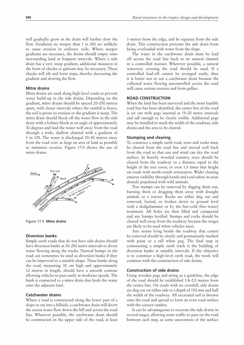
390 Rural structures in the tropics: design and development
will gradually grow in the drain will further slow the flow. Gradients no steeper than 1 in 250 are unlikely to cause erosion in ordinary soils. Where steeper gradients are necessary, the drains should empty onto surrounding land at frequent intervals. Where a side drain has a very steep gradient, additional measures in the form of checks or gabions may be necessary. These checks will silt and form steps, thereby decreasing the gradient and slowing the flow.
Mitre drainsMitre drains are used along high-level roads to prevent water build-up in the side drains. Depending on the gradient, mitre drains should be spaced 20–250 metres apart, with closer intervals where the rainfall is heavy, the soil is prone to erosion or the gradient is steep. The mitre drain should block off the water flow in the side drain with a bolster block at an angle of approximately 30 degrees and lead the water well away from the road through a wide, shallow channel with a gradient of 1 in 125. The water is discharged 30–40 metres away from the road over as large an area of land as possible to minimize erosion. Figure 17.5 shows the use of mitre drains.
Figure 17.5 Mitre drains
diversion banksSimple earth roads that do not have side drains should have diversion banks at 30–250 metre intervals to divert water flowing along the tracks. Natural bumps in the road can sometimes be used as diversion banks if they can be improved to a suitable shape. These banks along the road, measuring 30 cm high and approximately 12 metres in length, should have a smooth contour allowing vehicles to pass easily at moderate speeds. The bank is connected to a mitre drain that feeds the water onto the adjacent land.
catchwater drainsWhere a road is constructed along the lower part of a slope or cut into a hillside, a catchwater drain will divert the excess water flow down the hill and across the road line. Wherever possible, the catchwater drain should be constructed on the upper side of the road, at least
SlopeRun out
Bank
side d
rain
side d
rain
20-250 m depending on
gradient
Roadway
1:25
3 metres from the edge, and be separate from the side drain. This construction prevents the side drain from being overloaded with water from the slope.
The water in the catchwater drain must be lead off across the road line back to its natural channel in a controlled manner. Wherever possible, a natural waterway crossing the road should be used. If a controlled lead-off cannot be arranged easily, then it is better not to use a catchwater drain because the collected water flowing uncontrolled across the road will cause serious erosion and form gullies.
Road conStRuctIonWhen the land has been surveyed and the most feasible road line has been identified, the centre line of the road is set out with pegs inserted at 15–20 metre intervals and tall enough to be clearly visible. Additional pegs may be installed to mark the width of the roadway, side drains and the area to be cleared.
Stumping and clearingTo construct a simple earth road, trees and rocks must be cleared from the road line and moved well back from the road so that sun and wind can dry the road surface. In heavily wooded country, trees should be cleared from the roadway to a distance equal to the height of the tree cover, or even 1.5 times that height on roads with north–south orientation. Wider clearing ensures visibility through bends and road safety in areas densely populated with wild animals.
Tree stumps can be removed by digging them out, burning them or dragging them away with draught animals or a tractor. Rocks are either dug out and removed, buried, or broken down to ground level with a sledgehammer or by the hot–cold (fire–water) treatment. All holes are then filled and compacted and any bumps levelled. Stumps and rocks should be cleared well away from the roadway because the verges are likely to be used when vehicles meet.
Any stones lying beside the roadway that cannot be removed should be clearly and permanently marked with paint or a tall white peg. The final step in constructing a simple earth track is the building of diversion banks at suitable intervals. If the objective is to construct a high-level earth road, the work will continue with the construction of side drains.
construction of side drainsUsing wooden pegs and string as a guideline, the edge of the road should be established 1.8–2.0 metres from the centre line. On roads with no crossfall, side drains are dug out on either side to a depth of 150 mm and half the width of the roadway. All excavated soil is thrown onto the road and spread to form an even road surface with the correct camber.
It can be advantageous to excavate the side drains in several stages, allowing some traffic to pass on the road between each step, as some unevenness of the surface
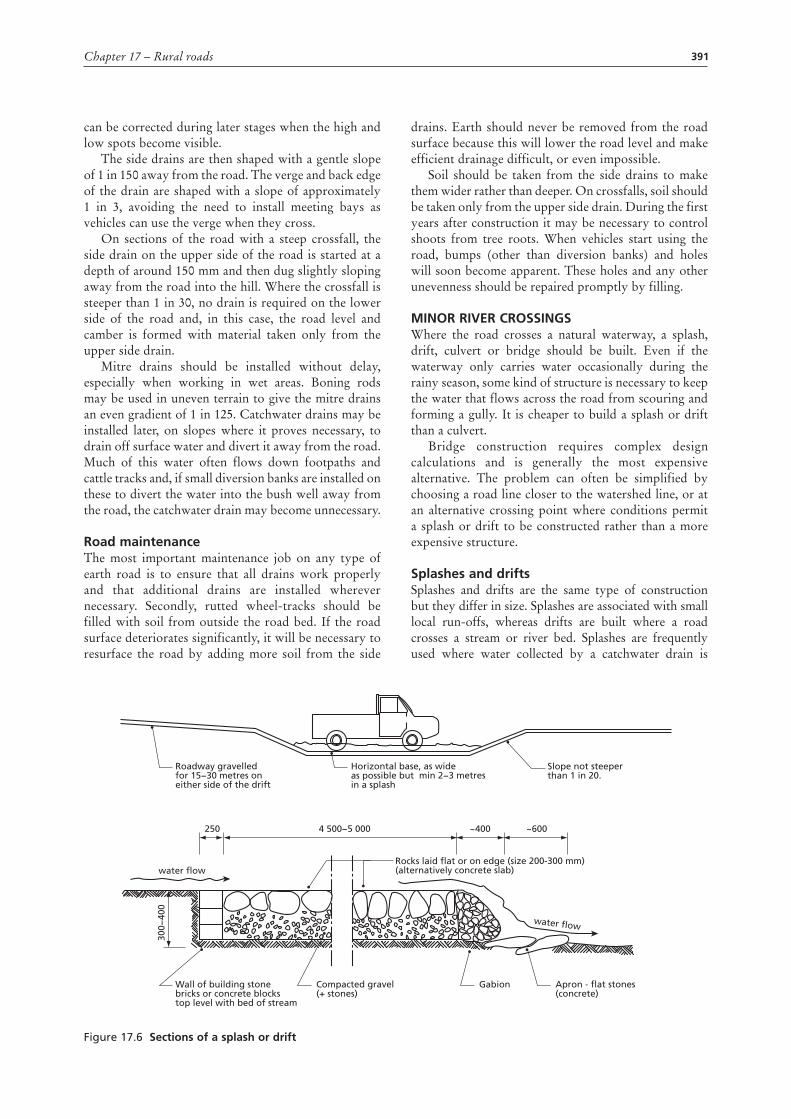
391Chapter 17 – Rural roads
can be corrected during later stages when the high and low spots become visible.
The side drains are then shaped with a gentle slope of 1 in 150 away from the road. The verge and back edge of the drain are shaped with a slope of approximately 1 in 3, avoiding the need to install meeting bays as vehicles can use the verge when they cross.
On sections of the road with a steep crossfall, the side drain on the upper side of the road is started at a depth of around 150 mm and then dug slightly sloping away from the road into the hill. Where the crossfall is steeper than 1 in 30, no drain is required on the lower side of the road and, in this case, the road level and camber is formed with material taken only from the upper side drain.
Mitre drains should be installed without delay, especially when working in wet areas. Boning rods may be used in uneven terrain to give the mitre drains an even gradient of 1 in 125. Catchwater drains may be installed later, on slopes where it proves necessary, to drain off surface water and divert it away from the road. Much of this water often flows down footpaths and cattle tracks and, if small diversion banks are installed on these to divert the water into the bush well away from the road, the catchwater drain may become unnecessary.
Road maintenanceThe most important maintenance job on any type of earth road is to ensure that all drains work properly and that additional drains are installed wherever necessary. Secondly, rutted wheel-tracks should be filled with soil from outside the road bed. If the road surface deteriorates significantly, it will be necessary to resurface the road by adding more soil from the side
drains. Earth should never be removed from the road surface because this will lower the road level and make efficient drainage difficult, or even impossible.
Soil should be taken from the side drains to make them wider rather than deeper. On crossfalls, soil should be taken only from the upper side drain. During the first years after construction it may be necessary to control shoots from tree roots. When vehicles start using the road, bumps (other than diversion banks) and holes will soon become apparent. These holes and any other unevenness should be repaired promptly by filling.
MInoR RIvER cRoSSInGSWhere the road crosses a natural waterway, a splash, drift, culvert or bridge should be built. Even if the waterway only carries water occasionally during the rainy season, some kind of structure is necessary to keep the water that flows across the road from scouring and forming a gully. It is cheaper to build a splash or drift than a culvert.
Bridge construction requires complex design calculations and is generally the most expensive alternative. The problem can often be simplified by choosing a road line closer to the watershed line, or at an alternative crossing point where conditions permit a splash or drift to be constructed rather than a more expensive structure.
Splashes and driftsSplashes and drifts are the same type of construction but they differ in size. Splashes are associated with small local run-offs, whereas drifts are built where a road crosses a stream or river bed. Splashes are frequently used where water collected by a catchwater drain is
Figure 17.6 Sections of a splash or drift
Roadway gravelledfor 15−30 metres oneither side of the drift
250
water flow
300−
400
water flow
~400 ~6004 500−5 000
Wall of building stonebricks or concrete blockstop level with bed of stream
Compacted gravel(+ stones)
Gabion Apron - flat stones(concrete)
Rocks laid flat or on edge (size 200-300 mm)(alternatively concrete slab)
Horizontal base, as wideas possible but min 2−3 metresin a splash
Slope not steeperthan 1 in 20.
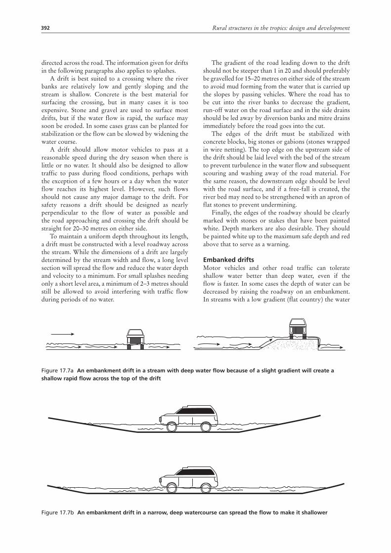
392 Rural structures in the tropics: design and development
directed across the road. The information given for drifts in the following paragraphs also applies to splashes.
A drift is best suited to a crossing where the river banks are relatively low and gently sloping and the stream is shallow. Concrete is the best material for surfacing the crossing, but in many cases it is too expensive. Stone and gravel are used to surface most drifts, but if the water flow is rapid, the surface may soon be eroded. In some cases grass can be planted for stabilization or the flow can be slowed by widening the water course.
A drift should allow motor vehicles to pass at a reasonable speed during the dry season when there is little or no water. It should also be designed to allow traffic to pass during flood conditions, perhaps with the exception of a few hours or a day when the water flow reaches its highest level. However, such flows should not cause any major damage to the drift. For safety reasons a drift should be designed as nearly perpendicular to the flow of water as possible and the road approaching and crossing the drift should be straight for 20–30 metres on either side.
To maintain a uniform depth throughout its length, a drift must be constructed with a level roadway across the stream. While the dimensions of a drift are largely determined by the stream width and flow, a long level section will spread the flow and reduce the water depth and velocity to a minimum. For small splashes needing only a short level area, a minimum of 2–3 metres should still be allowed to avoid interfering with traffic flow during periods of no water.
The gradient of the road leading down to the drift should not be steeper than 1 in 20 and should preferably be gravelled for 15–20 metres on either side of the stream to avoid mud forming from the water that is carried up the slopes by passing vehicles. Where the road has to be cut into the river banks to decrease the gradient, run-off water on the road surface and in the side drains should be led away by diversion banks and mitre drains immediately before the road goes into the cut.
The edges of the drift must be stabilized with concrete blocks, big stones or gabions (stones wrapped in wire netting). The top edge on the upstream side of the drift should be laid level with the bed of the stream to prevent turbulence in the water flow and subsequent scouring and washing away of the road material. For the same reason, the downstream edge should be level with the road surface, and if a free-fall is created, the river bed may need to be strengthened with an apron of flat stones to prevent undermining.
Finally, the edges of the roadway should be clearly marked with stones or stakes that have been painted white. Depth markers are also desirable. They should be painted white up to the maximum safe depth and red above that to serve as a warning.
Embanked driftsMotor vehicles and other road traffic can tolerate shallow water better than deep water, even if the flow is faster. In some cases the depth of water can be decreased by raising the roadway on an embankment. In streams with a low gradient (flat country) the water
Figure 17.7a an embankment drift in a stream with deep water flow because of a slight gradient will create a shallow rapid flow across the top of the drift
Figure 17.7b an embankment drift in a narrow, deep watercourse can spread the flow to make it shallower
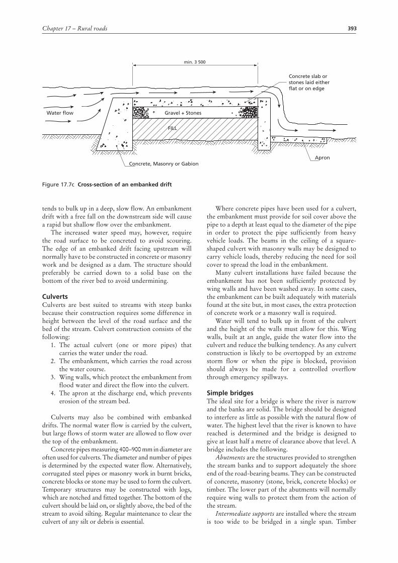
393Chapter 17 – Rural roads
tends to bulk up in a deep, slow flow. An embankment drift with a free fall on the downstream side will cause a rapid but shallow flow over the embankment.
The increased water speed may, however, require the road surface to be concreted to avoid scouring. The edge of an embanked drift facing upstream will normally have to be constructed in concrete or masonry work and be designed as a dam. The structure should preferably be carried down to a solid base on the bottom of the river bed to avoid undermining.
culvertsCulverts are best suited to streams with steep banks because their construction requires some difference in height between the level of the road surface and the bed of the stream. Culvert construction consists of the following:
1. The actual culvert (one or more pipes) that carries the water under the road.
2. The embankment, which carries the road across the water course.
3. Wing walls, which protect the embankment from flood water and direct the flow into the culvert.
4. The apron at the discharge end, which prevents erosion of the stream bed.
Culverts may also be combined with embanked drifts. The normal water flow is carried by the culvert, but large flows of storm water are allowed to flow over the top of the embankment.
Concrete pipes measuring 400–900 mm in diameter are often used for culverts. The diameter and number of pipes is determined by the expected water flow. Alternatively, corrugated steel pipes or masonry work in burnt bricks, concrete blocks or stone may be used to form the culvert. Temporary structures may be constructed with logs, which are notched and fitted together. The bottom of the culvert should be laid on, or slightly above, the bed of the stream to avoid silting. Regular maintenance to clear the culvert of any silt or debris is essential.
Where concrete pipes have been used for a culvert, the embankment must provide for soil cover above the pipe to a depth at least equal to the diameter of the pipe in order to protect the pipe sufficiently from heavy vehicle loads. The beams in the ceiling of a square-shaped culvert with masonry walls may be designed to carry vehicle loads, thereby reducing the need for soil cover to spread the load in the embankment.
Many culvert installations have failed because the embankment has not been sufficiently protected by wing walls and have been washed away. In some cases, the embankment can be built adequately with materials found at the site but, in most cases, the extra protection of concrete work or a masonry wall is required.
Water will tend to bulk up in front of the culvert and the height of the walls must allow for this. Wing walls, built at an angle, guide the water flow into the culvert and reduce the bulking tendency. As any culvert construction is likely to be overtopped by an extreme storm flow or when the pipe is blocked, provision should always be made for a controlled overflow through emergency spillways.
Simple bridgesThe ideal site for a bridge is where the river is narrow and the banks are solid. The bridge should be designed to interfere as little as possible with the natural flow of water. The highest level that the river is known to have reached is determined and the bridge is designed to give at least half a metre of clearance above that level. A bridge includes the following.
Abutments are the structures provided to strengthen the stream banks and to support adequately the shore end of the road-bearing beams. They can be constructed of concrete, masonry (stone, brick, concrete blocks) or timber. The lower part of the abutments will normally require wing walls to protect them from the action of the stream.
Intermediate supports are installed where the stream is too wide to be bridged in a single span. Timber
Figure 17.7c cross-section of an embanked drift
min. 3 500
Water flow Gravel + Stones
Concrete, Masonry or Gabion
Concrete slab orstones laid eitherflat or on edge
Apron
FILL
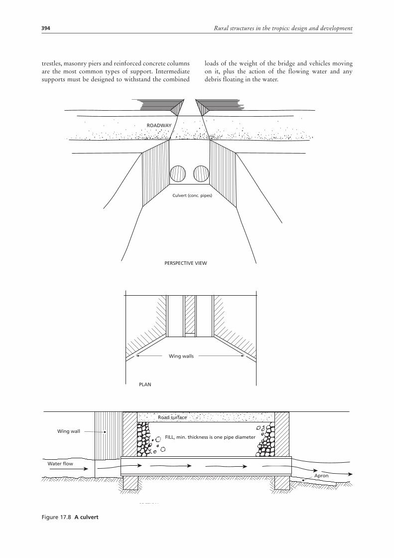
394 Rural structures in the tropics: design and development
trestles, masonry piers and reinforced concrete columns are the most common types of support. Intermediate supports must be designed to withstand the combined
loads of the weight of the bridge and vehicles moving on it, plus the action of the flowing water and any debris floating in the water.
Figure 17.8 a culvert
ROADWAY
Culvert (conc. pipes)
PERSPECTIVE VIEW
PLAN
SECTION
Road surface
FILL, min. thickness is one pipe diameterWing wall
Water flow
Apron
Wing walls
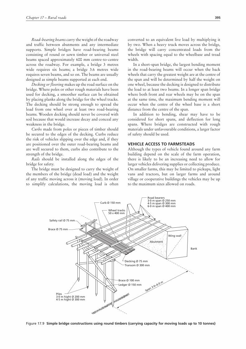
395Chapter 17 – Rural roads
Road-bearing beams carry the weight of the roadway and traffic between abutments and any intermediate supports. Simple bridges have road-bearing beams consisting of round or sawn timber or universal steel beams spaced approximately 600 mm centre-to-centre across the roadway. For example, a bridge 3 metres wide requires six beams; a bridge 3.6 metres wide requires seven beams, and so on. The beams are usually designed as simple beams supported at each end.
Decking or flooring makes up the road surface on the bridge. Where poles or other rough materials have been used for decking, a smoother surface can be obtained by placing planks along the bridge for the wheel tracks. The decking should be strong enough to spread the load from one wheel over at least two road-bearing beams. Wooden decking should never be covered with soil because that would increase decay and conceal any weakness in the bridge.
Curbs made from poles or pieces of timber should be secured to the edges of the decking. Curbs reduce the risk of vehicles slipping over the edge and, if they are positioned over the outer road-bearing beams and are well secured to them, curbs also contribute to the strength of the bridge.
Rails should be installed along the edges of the bridge for safety.
The bridge must be designed to carry the weight of the members of the bridge (dead load) and the weight of any traffic moving across it (moving load). In order to simplify calculations, the moving load is often
converted to an equivalent live load by multiplying it by two. When a heavy truck moves across the bridge, the bridge will carry concentrated loads from the wheels with spacing equal to the wheelbase and tread width.
In a short-span bridge, the largest bending moment in the road-bearing beams will occur when the back wheels that carry the greatest weight are at the centre of the span and will be determined by half the weight on one wheel, because the decking is designed to distribute the load to at least two beams. In a longer span bridge where both front and rear wheels may be on the span at the same time, the maximum bending moment will occur when the centre of the wheel base is a short distance from the centre of the span.
In addition to bending, shear may have to be considered for short spans, and deflection for long spans. Where bridges are constructed with rough materials under unfavourable conditions, a larger factor of safety should be used.
vEhIclE accESS to faRMStEadSAlthough the types of vehicle found around any farm building depend on the scale of the farm operation, there is likely to be an increasing need to allow for larger vehicles delivering supplies or collecting produce. On smaller farms, this may be limited to pickups, light vans and tractors, but on larger farms and around village or cooperative buildings the vehicles may be up to the maximum sizes allowed on roads.
Figure 17.9 Simple bridge constructions using round timbers (carrying capacity for moving loads up to 10 tonnes)
Abutment
Road bearers3·0 m span Ø 250 mm4·5 m span Ø 300 mm 6·0 m span Ø 400 mm
Curb Ø 150 mm
Safety rail Ø 75 mm
Brace Ø 75 mm
Brace Ø 100 mm
Transom Ø 300 mm Decking Ø 75 mm
Ledger Ø 150 mm
Piles3∙0 m hight Ø 200 mm 4∙5 m hight Ø 300 mm
Wheel tracks50 x 400 mm
Wing wall
Bank
Span 3∙0−6∙0 m
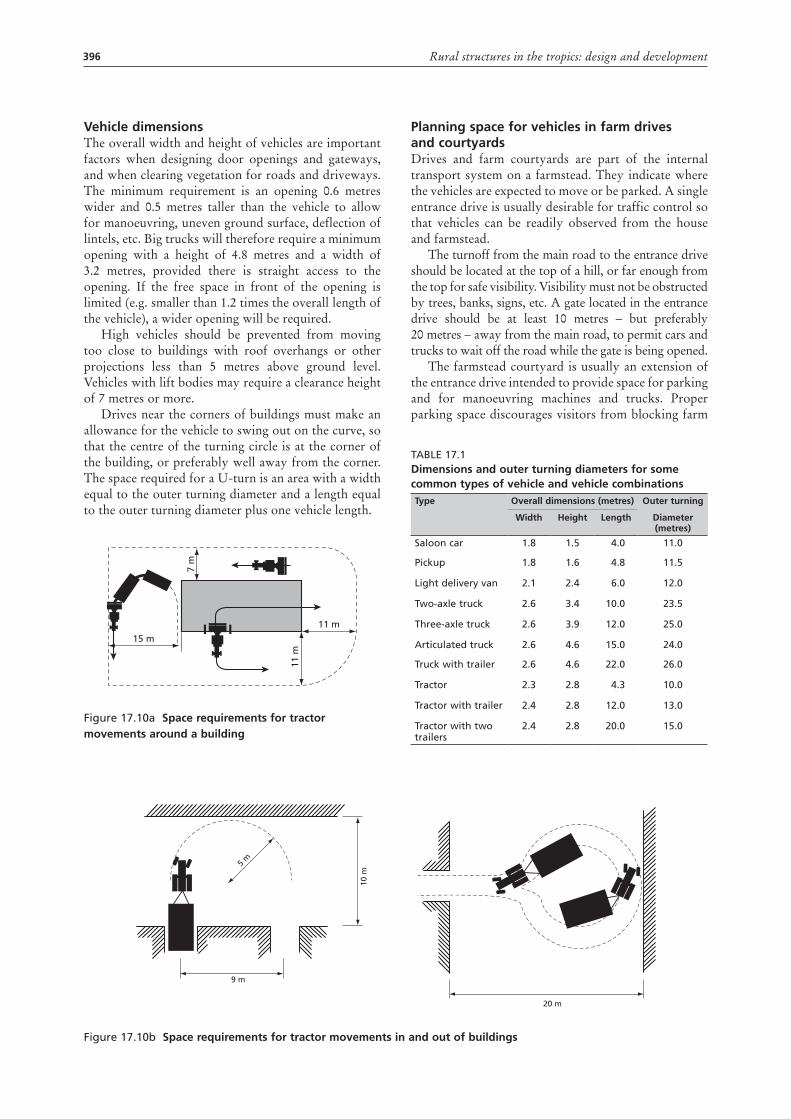
396 Rural structures in the tropics: design and development
vehicle dimensionsThe overall width and height of vehicles are important factors when designing door openings and gateways, and when clearing vegetation for roads and driveways. The minimum requirement is an opening 0.6 metres wider and 0.5 metres taller than the vehicle to allow for manoeuvring, uneven ground surface, deflection of lintels, etc. Big trucks will therefore require a minimum opening with a height of 4.8 metres and a width of 3.2 metres, provided there is straight access to the opening. If the free space in front of the opening is limited (e.g. smaller than 1.2 times the overall length of the vehicle), a wider opening will be required.
High vehicles should be prevented from moving too close to buildings with roof overhangs or other projections less than 5 metres above ground level. Vehicles with lift bodies may require a clearance height of 7 metres or more.
Drives near the corners of buildings must make an allowance for the vehicle to swing out on the curve, so that the centre of the turning circle is at the corner of the building, or preferably well away from the corner. The space required for a U-turn is an area with a width equal to the outer turning diameter and a length equal to the outer turning diameter plus one vehicle length.
Figure 17.10a Space requirements for tractor movements around a building
15 m
11 m
7 m
11 m
Planning space for vehicles in farm drivesand courtyardsDrives and farm courtyards are part of the internal transport system on a farmstead. They indicate where the vehicles are expected to move or be parked. A single entrance drive is usually desirable for traffic control so that vehicles can be readily observed from the house and farmstead.
The turnoff from the main road to the entrance drive should be located at the top of a hill, or far enough from the top for safe visibility. Visibility must not be obstructed by trees, banks, signs, etc. A gate located in the entrance drive should be at least 10 metres – but preferably 20 metres – away from the main road, to permit cars and trucks to wait off the road while the gate is being opened.
The farmstead courtyard is usually an extension of the entrance drive intended to provide space for parking and for manoeuvring machines and trucks. Proper parking space discourages visitors from blocking farm
Figure 17.10b Space requirements for tractor movements in and out of buildings
9 m
20 m
5 m
10 m
Table 17.1dimensions and outer turning diameters for some common types of vehicle and vehicle combinationstype overall dimensions (metres) outer turning
Width height length diameter (metres)
Saloon car 1.8 1.5 4.0 11.0
Pickup 1.8 1.6 4.8 11.5
light delivery van 2.1 2.4 6.0 12.0
Two-axle truck 2.6 3.4 10.0 23.5
Three-axle truck 2.6 3.9 12.0 25.0
articulated truck 2.6 4.6 15.0 24.0
Truck with trailer 2.6 4.6 22.0 26.0
Tractor 2.3 2.8 4.3 10.0
Tractor with trailer 2.4 2.8 12.0 13.0
Tractor with two trailers
2.4 2.8 20.0 15.0
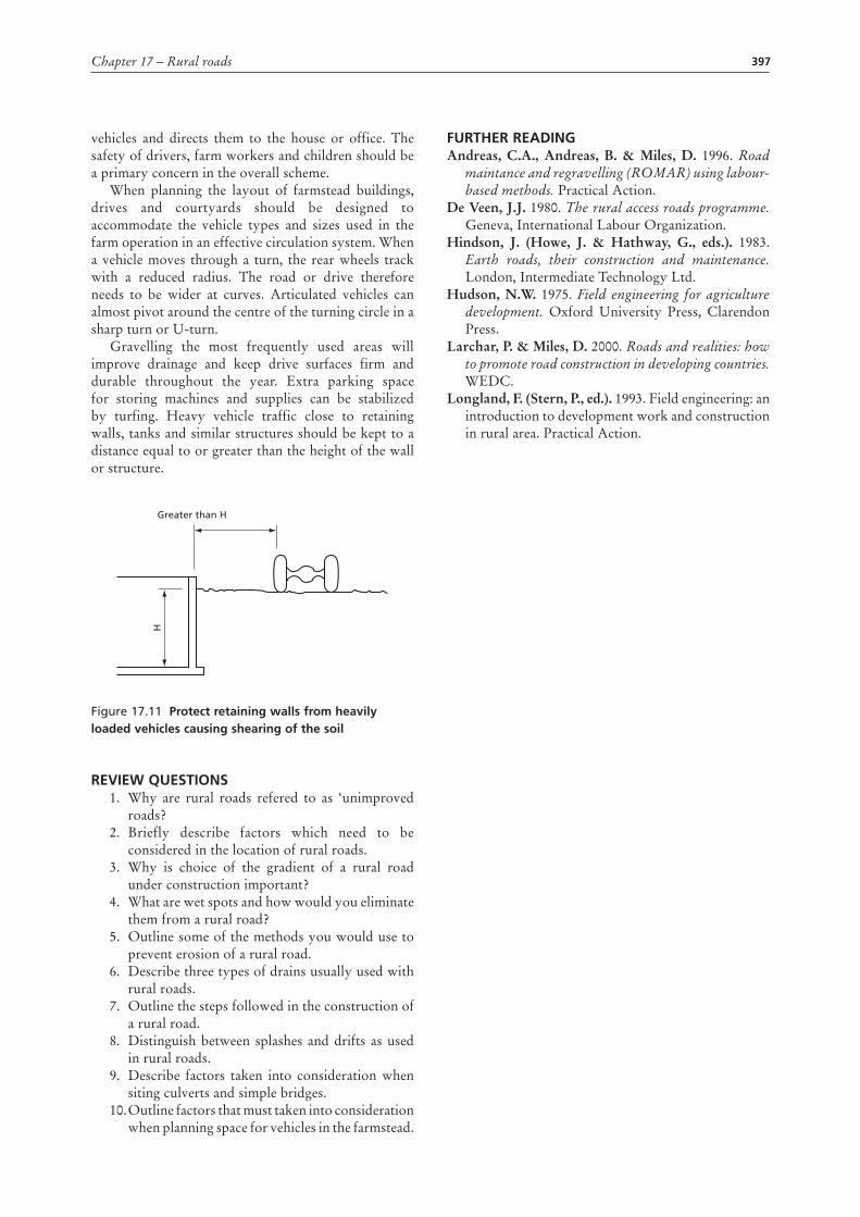
397Chapter 17 – Rural roads
vehicles and directs them to the house or office. The safety of drivers, farm workers and children should be a primary concern in the overall scheme.
When planning the layout of farmstead buildings, drives and courtyards should be designed to accommodate the vehicle types and sizes used in the farm operation in an effective circulation system. When a vehicle moves through a turn, the rear wheels track with a reduced radius. The road or drive therefore needs to be wider at curves. Articulated vehicles can almost pivot around the centre of the turning circle in a sharp turn or U-turn.
Gravelling the most frequently used areas will improve drainage and keep drive surfaces firm and durable throughout the year. Extra parking space for storing machines and supplies can be stabilized by turfing. Heavy vehicle traffic close to retaining walls, tanks and similar structures should be kept to a distance equal to or greater than the height of the wall or structure.
Figure 17.11 Protect retaining walls from heavily loaded vehicles causing shearing of the soil
REvIEW quEStIonS1. Why are rural roads refered to as ‘unimproved
roads?2. Briefly describe factors which need to be
considered in the location of rural roads.3. Why is choice of the gradient of a rural road
under construction important?4. What are wet spots and how would you eliminate
them from a rural road?5. Outline some of the methods you would use to
prevent erosion of a rural road.6. Describe three types of drains usually used with
rural roads.7. Outline the steps followed in the construction of
a rural road.8. Distinguish between splashes and drifts as used
in rural roads.9. Describe factors taken into consideration when
siting culverts and simple bridges.10. Outline factors that must taken into consideration
when planning space for vehicles in the farmstead.
Greater than H
H
fuRthER REadInGAndreas, C.A., Andreas, B. & Miles, D. 1996. Road
maintance and regravelling (ROMAR) using labour-based methods. Practical Action.
De Veen, J.J. 1980. The rural access roads programme. Geneva, International Labour Organization.
Hindson, J. (Howe, J. & Hathway, G., eds.). 1983. Earth roads, their construction and maintenance. London, Intermediate Technology Ltd.
Hudson, N.W. 1975. Field engineering for agriculture development. Oxford University Press, Clarendon Press.
Larchar, P. & Miles, D. 2000. Roads and realities: how to promote road construction in developing countries. WEDC.
Longland, F. (Stern, P., ed.). 1993. Field engineering: an introduction to development work and construction in rural area. Practical Action.
399
Chapter 18
External facilities
This chapter deals with rural structures that are only indirectly related to buildings but are of great importance to agricultural production and the provision of services in rural areas. These include fences, farmstead courtyards, fencing and animal-handling yards.
FEncingThe two main objectives of fencing on a farm are to improve security and livestock management, but fences may also be used as windbreaks, to provide privacy and to enhance appearance. The type of fence chosen for a specific situation is normally determined by the objective, or the combination of objectives, for which it is built.
SecurityFencing is often used to protect property and growing crops from theft and damage by people or animals. It is also useful in pasture management when used to divide paddocks. Where the objective is solely to demarcate boundaries, very simple structures may suffice. On the other hand, fences that are designed to stop intruders from entering must be high, dense and sturdy, and be topped with spikes or barbs. As secure fences can be quite expensive, their use is limited to enclosing particularly valuable property.
The three most widely used types of fence for this purpose are:
1. Round or square vertical bars of wood or steel, secured to horizontal rails and fixed to posts set 2–3 metres apart. These are very difficult to climb.
2. Chain-link (diamond-mesh) netting, about 2 metres high and fixed to posts set 3 metres apart. In both types of fence, stays may be used for extra strength, with a barbed-wire top for extra security.
3. Thorny hedges.
Fencing is also used for protection around ponds, along steep slopes or in other hazardous locations.
improved livestock managementHerding is the traditional method of controlling livestock movements during grazing. In the past, fencing was used only to exclude animals from certain areas, such as homesteads and cultivated fields, and to safeguard them at night.
With ‘extensive’ livestock production, fencing is likely to be so costly that the practice of herding must continue. However, it is not uncommon to enclose the land with a boundary fence. With ‘intensive’ livestock production, it is often feasible to subdivide the land. The greater number of paddocks allows for flexibility in herding livestock and dividing them into different classes or age groups. It is seldom economical to subdivide the land beyond what is necessary for efficient grazing.
In Africa, some of the worst livestock diseases are tick-borne, and fencing can play an important role in breaking the disease cycle by maintaining the disease-free condition of livestock once enough ticks have been eradicated by regular spraying or dipping. Fencing also helps to limit the spread of other infectious diseases, and to reduce problems with parasites. In addition, fencing can be used to prevent improved animals from breeding with animals from outside the farm.
In intensive dairy production, the animals are often grouped according to production to allow for more efficient feeding of concentrates and for improved management practices. The various groups of animals are kept separate by fences and other structures, such as feed racks.
TypES oF FEncESAny type of structure that forms an effective barrier to livestock movements, or restricts human movements, can be termed a fence. The following are the most common types of fence on farms.
Wire fences, such as:• plain-wire fences• barbed-wire fences• suspension fences • wire-netting fences • electric fences
Other types of fence, such as:• post and rail fences • hedges • log fences• walls• movable fences
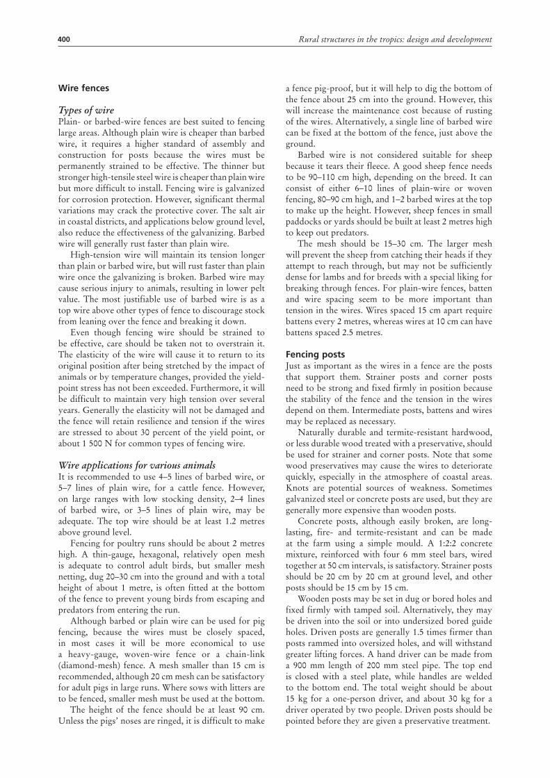
400 Rural structures in the tropics: design and development
Wire fences
Types of wirePlain- or barbed-wire fences are best suited to fencing large areas. Although plain wire is cheaper than barbed wire, it requires a higher standard of assembly and construction for posts because the wires must be permanently strained to be effective. The thinner but stronger high-tensile steel wire is cheaper than plain wire but more difficult to install. Fencing wire is galvanized for corrosion protection. However, significant thermal variations may crack the protective cover. The salt air in coastal districts, and applications below ground level, also reduce the effectiveness of the galvanizing. Barbed wire will generally rust faster than plain wire.
High-tension wire will maintain its tension longer than plain or barbed wire, but will rust faster than plain wire once the galvanizing is broken. Barbed wire may cause serious injury to animals, resulting in lower pelt value. The most justifiable use of barbed wire is as a top wire above other types of fence to discourage stock from leaning over the fence and breaking it down.
Even though fencing wire should be strained to be effective, care should be taken not to overstrain it. The elasticity of the wire will cause it to return to its original position after being stretched by the impact of animals or by temperature changes, provided the yield-point stress has not been exceeded. Furthermore, it will be difficult to maintain very high tension over several years. Generally the elasticity will not be damaged and the fence will retain resilience and tension if the wires are stressed to about 30 percent of the yield point, or about 1 500 N for common types of fencing wire.
Wire applications for various animalsIt is recommended to use 4–5 lines of barbed wire, or 5–7 lines of plain wire, for a cattle fence. However, on large ranges with low stocking density, 2–4 lines of barbed wire, or 3–5 lines of plain wire, may be adequate. The top wire should be at least 1.2 metres above ground level.
Fencing for poultry runs should be about 2 metres high. A thin-gauge, hexagonal, relatively open mesh is adequate to control adult birds, but smaller mesh netting, dug 20–30 cm into the ground and with a total height of about 1 metre, is often fitted at the bottom of the fence to prevent young birds from escaping and predators from entering the run.
Although barbed or plain wire can be used for pig fencing, because the wires must be closely spaced, in most cases it will be more economical to use a heavy-gauge, woven-wire fence or a chain-link (diamond-mesh) fence. A mesh smaller than 15 cm is recommended, although 20 cm mesh can be satisfactory for adult pigs in large runs. Where sows with litters are to be fenced, smaller mesh must be used at the bottom.
The height of the fence should be at least 90 cm. Unless the pigs’ noses are ringed, it is difficult to make
a fence pig-proof, but it will help to dig the bottom of the fence about 25 cm into the ground. However, this will increase the maintenance cost because of rusting of the wires. Alternatively, a single line of barbed wire can be fixed at the bottom of the fence, just above the ground.
Barbed wire is not considered suitable for sheep because it tears their fleece. A good sheep fence needs to be 90–110 cm high, depending on the breed. It can consist of either 6–10 lines of plain-wire or woven fencing, 80–90 cm high, and 1–2 barbed wires at the top to make up the height. However, sheep fences in small paddocks or yards should be built at least 2 metres high to keep out predators.
The mesh should be 15–30 cm. The larger mesh will prevent the sheep from catching their heads if they attempt to reach through, but may not be sufficiently dense for lambs and for breeds with a special liking for breaking through fences. For plain-wire fences, batten and wire spacing seem to be more important than tension in the wires. Wires spaced 15 cm apart require battens every 2 metres, whereas wires at 10 cm can have battens spaced 2.5 metres.
Fencing postsJust as important as the wires in a fence are the posts that support them. Strainer posts and corner posts need to be strong and fixed firmly in position because the stability of the fence and the tension in the wires depend on them. Intermediate posts, battens and wires may be replaced as necessary.
Naturally durable and termite-resistant hardwood, or less durable wood treated with a preservative, should be used for strainer and corner posts. Note that some wood preservatives may cause the wires to deteriorate quickly, especially in the atmosphere of coastal areas. Knots are potential sources of weakness. Sometimes galvanized steel or concrete posts are used, but they are generally more expensive than wooden posts.
Concrete posts, although easily broken, are long-lasting, fire- and termite-resistant and can be made at the farm using a simple mould. A 1:2:2 concrete mixture, reinforced with four 6 mm steel bars, wired together at 50 cm intervals, is satisfactory. Strainer posts should be 20 cm by 20 cm at ground level, and other posts should be 15 cm by 15 cm.
Wooden posts may be set in dug or bored holes and fixed firmly with tamped soil. Alternatively, they may be driven into the soil or into undersized bored guide holes. Driven posts are generally 1.5 times firmer than posts rammed into oversized holes, and will withstand greater lifting forces. A hand driver can be made from a 900 mm length of 200 mm steel pipe. The top end is closed with a steel plate, while handles are welded to the bottom end. The total weight should be about 15 kg for a one-person driver, and about 30 kg for a driver operated by two people. Driven posts should be pointed before they are given a preservative treatment.
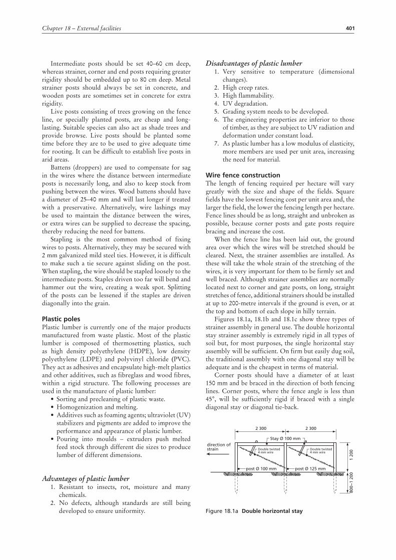
401Chapter 18 – External facilities
Intermediate posts should be set 40–60 cm deep, whereas strainer, corner and end posts requiring greater rigidity should be embedded up to 80 cm deep. Metal strainer posts should always be set in concrete, and wooden posts are sometimes set in concrete for extra rigidity.
Live posts consisting of trees growing on the fence line, or specially planted posts, are cheap and long-lasting. Suitable species can also act as shade trees and provide browse. Live posts should be planted some time before they are to be used to give adequate time for rooting. It can be difficult to establish live posts in arid areas.
Battens (droppers) are used to compensate for sag in the wires where the distance between intermediate posts is necessarily long, and also to keep stock from pushing between the wires. Wood battens should have a diameter of 25–40 mm and will last longer if treated with a preservative. Alternatively, wire lashings may be used to maintain the distance between the wires, or extra wires can be supplied to decrease the spacing, thereby reducing the need for battens.
Stapling is the most common method of fixing wires to posts. Alternatively, they may be secured with 2 mm galvanized mild steel ties. However, it is difficult to make such a tie secure against sliding on the post. When stapling, the wire should be stapled loosely to the intermediate posts. Staples driven too far will bend and hammer out the wire, creating a weak spot. Splitting of the posts can be lessened if the staples are driven diagonally into the grain.
plastic polesPlastic lumber is currently one of the major products manufactured from waste plastic. Most of the plastic lumber is composed of thermosetting plastics, such as high density polyethylene (HDPE), low density polyethylene (LDPE) and polyvinyl chloride (PVC). They act as adhesives and encapsulate high-melt plastics and other additives, such as fibreglass and wood fibres, within a rigid structure. The following processes are used in the manufacture of plastic lumber:
• Sorting and precleaning of plastic waste.• Homogenization and melting.• Additives such as foaming agents; ultraviolet (UV)
stabilizers and pigments are added to improve the performance and appearance of plastic lumber.
• Pouring into moulds – extruders push melted feed stock through different die sizes to produce lumber of different dimensions.
Advantages of plastic lumber1. Resistant to insects, rot, moisture and many
chemicals.2. No defects, although standards are still being
developed to ensure uniformity.
Disadvantages of plastic lumber1. Very sensitive to temperature (dimensional
changes).2. High creep rates.3. High flammability.4. UV degradation.5. Grading system needs to be developed.6. The engineering properties are inferior to those
of timber, as they are subject to UV radiation and deformation under constant load.
7. As plastic lumber has a low modulus of elasticity, more members are used per unit area, increasing the need for material.
Wire fence constructionThe length of fencing required per hectare will vary greatly with the size and shape of the fields. Square fields have the lowest fencing cost per unit area and, the larger the field, the lower the fencing length per hectare. Fence lines should be as long, straight and unbroken as possible, because corner posts and gate posts require bracing and increase the cost.
When the fence line has been laid out, the ground area over which the wires will be stretched should be cleared. Next, the strainer assemblies are installed. As these will take the whole strain of the stretching of the wires, it is very important for them to be firmly set and well braced. Although strainer assemblies are normally located next to corner and gate posts, on long, straight stretches of fence, additional strainers should be installed at up to 200-metre intervals if the ground is even, or at the top and bottom of each slope in hilly terrain.
Figures 18.1a, 18.1b and 18.1c show three types of strainer assembly in general use. The double horizontal stay strainer assembly is extremely rigid in all types of soil but, for most purposes, the single horizontal stay assembly will be sufficient. On firm but easily dug soil, the traditional assembly with one diagonal stay will be adequate and is the cheapest in terms of material.
Corner posts should have a diameter of at least 150 mm and be braced in the direction of both fencing lines. Corner posts, where the fence angle is less than 45°, will be sufficiently rigid if braced with a single diagonal stay or diagonal tie-back.
Figure 18.1a Double horizontal stay
direction ofstrain
2 300
post Ø 100 mm
Stay Ø 100 mm
Double twisted4 mm wire
Double twisted4 mm wire
post Ø 125 mm
2 300
1 20
080
0−1
200
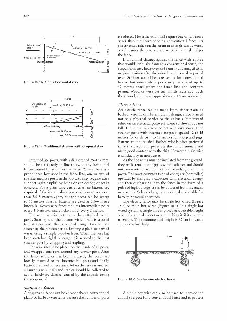
402 Rural structures in the tropics: design and development
Figure 18.1b Single horizontal stay
Figure 18.1c Traditional strainer with diagonal stay
Intermediate posts, with a diameter of 75–125 mm, should be set exactly in line to avoid any horizontal forces caused by strain in the wires. Where there is a pronounced low spot in the fence line, one or two of the intermediate posts in the low area may require extra support against uplift by being driven deeper, or set in concrete. For a plain-wire cattle fence, no battens are required if the intermediate posts are spaced no more than 3.5–5 metres apart, but the posts can be set up to 15 metres apart if battens are used at 3.5–4 metre intervals. Woven wire fence requires intermediate posts every 4–5 metres, and chicken wire, every 2 metres.
The wire, or wire netting, is then attached to the posts. Starting with the bottom wire, first it is secured to a strainer post, then stretched using a tackle-block stretcher, chain stretcher or, for single plain or barbed wires, using a simple wooden lever. When the wire has been stretched tightly enough, it is secured to the next strainer post by wrapping and stapling.
The wire should be placed on the inside of all posts, and wrapped one turn around any corner post. After the fence stretcher has been released, the wires are loosely fastened to the intermediate posts and finally battens are fixed as necessary. When the fence is erected, all surplus wire, nails and staples should be collected to avoid ‘hardware disease’ caused by the animals eating the scrap metal.
Suspension fencesA suspension fence can be cheaper than a conventional plain- or barbed-wire fence because the number of posts
Direction ofstrain Stay Ø 125 mm
Post Ø 150 mm
Post Ø 125 mmDouble twisted4 mm wire
3 200
1 20
080
0−1
200
Direction ofstrain
2 400
600
600
800−
1 00
0
post Ø 100 mm
post Ø 200 mm
Stay Ø 125 mm
is reduced. Nevertheless, it will require one or two more wires than the corresponding conventional fence. Its effectiveness relies on the strain in its high-tensile wires, which causes them to vibrate when an animal nudges the fence.
If an animal charges against the fence with a force that would seriously damage a conventional fence, the suspension fence heels over and returns undamaged to its original position after the animal has retreated or passed over. Strainer assemblies are set as for conventional fences, but intermediate posts may be spaced up to 40 metres apart where the fence line and contours permit. Wood or wire battens, which must not touch the ground, are spaced approximately 4.5 metres apart.
Electric fenceAn electric fence can be made from either plain or barbed wire. It can be simple in design, since it need not be a physical barrier to the animals, but instead relies on an electrical pulse sufficient to shock, but not kill. The wires are stretched between insulators at the strainer posts with intermediate posts spaced 12 to 15 metres for cattle or 7 to 12 metres for sheep and pigs. Battens are not needed. Barbed wire is often preferred since the barbs will penetrate the fur of animals and make good contact with the skin. However, plain wire is satisfactory in most cases.
As the hot wires must be insulated from the ground, they are fastened to the posts with insulators and should not come into direct contact with weeds, grass or the posts. The most common type of energizer (controller) operates by charging a capacitor with electrical energy and then discharging it to the fence in the form of a pulse of high voltage. It can be powered from the mains or a battery. Solar recharging units are also available for battery-powered energizers.
The electric fence may be single hot wired (Figure 18.2) or multi hot wired (Figure 18.3). In a single hot wired system, a single wire is placed at a suitable height where the animal cannot avoid touching it, if it attempts to escape. The recommended height is 60 cm for cattle and 25 cm for sheep.
Figure 18.2 Single-wire electric fence
A single hot wire can also be used to increase the animal’s respect for a conventional fence and to protect
Live
Earth
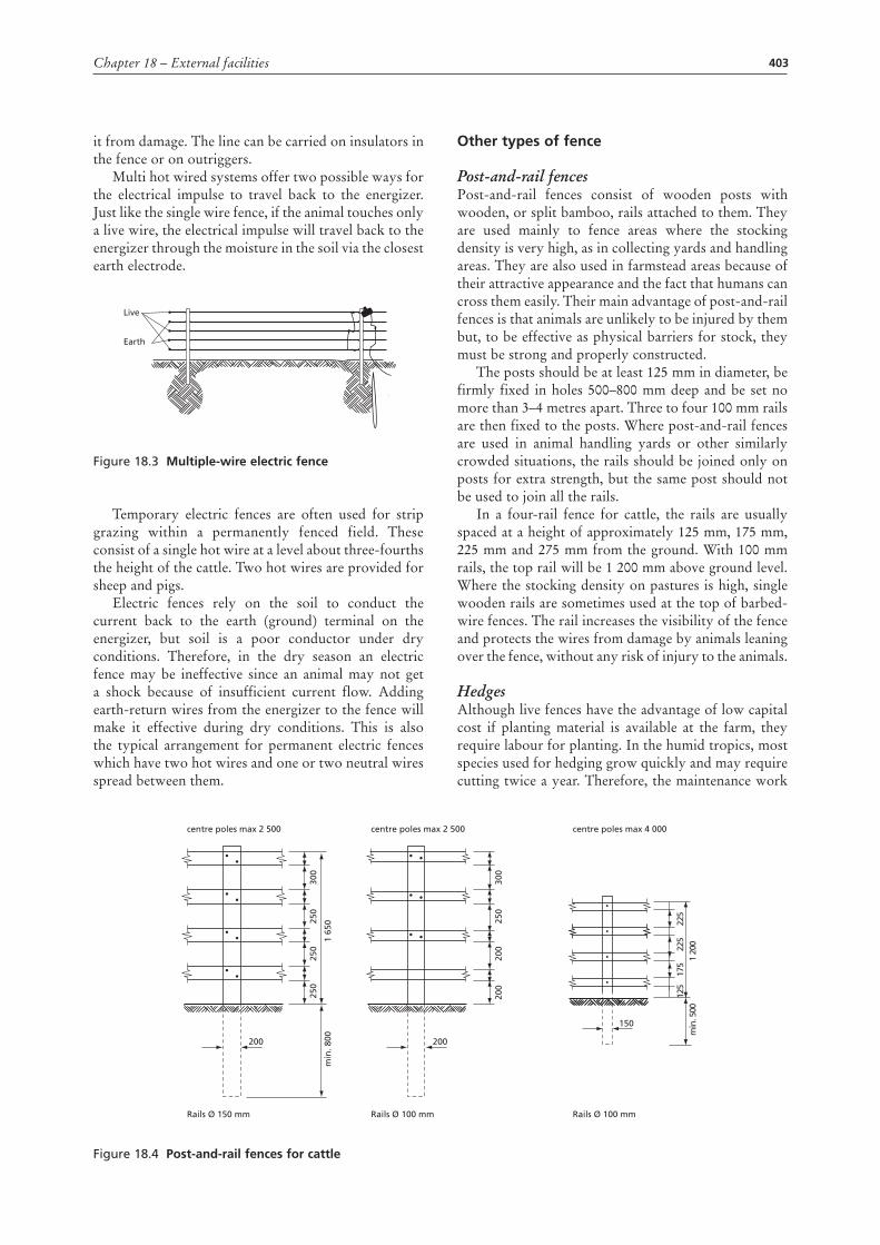
403Chapter 18 – External facilities
it from damage. The line can be carried on insulators in the fence or on outriggers.
Multi hot wired systems offer two possible ways for the electrical impulse to travel back to the energizer. Just like the single wire fence, if the animal touches only a live wire, the electrical impulse will travel back to the energizer through the moisture in the soil via the closest earth electrode.
Figure 18.3 Multiple-wire electric fence
Temporary electric fences are often used for strip grazing within a permanently fenced field. These consist of a single hot wire at a level about three-fourths the height of the cattle. Two hot wires are provided for sheep and pigs.
Electric fences rely on the soil to conduct the current back to the earth (ground) terminal on the energizer, but soil is a poor conductor under dry conditions. Therefore, in the dry season an electric fence may be ineffective since an animal may not get a shock because of insufficient current flow. Adding earth-return wires from the energizer to the fence will make it effective during dry conditions. This is also the typical arrangement for permanent electric fences which have two hot wires and one or two neutral wires spread between them.
Live
Earth
other types of fence
Post-and-rail fencesPost-and-rail fences consist of wooden posts with wooden, or split bamboo, rails attached to them. They are used mainly to fence areas where the stocking density is very high, as in collecting yards and handling areas. They are also used in farmstead areas because of their attractive appearance and the fact that humans can cross them easily. Their main advantage of post-and-rail fences is that animals are unlikely to be injured by them but, to be effective as physical barriers for stock, they must be strong and properly constructed.
The posts should be at least 125 mm in diameter, be firmly fixed in holes 500–800 mm deep and be set no more than 3–4 metres apart. Three to four 100 mm rails are then fixed to the posts. Where post-and-rail fences are used in animal handling yards or other similarly crowded situations, the rails should be joined only on posts for extra strength, but the same post should not be used to join all the rails.
In a four-rail fence for cattle, the rails are usually spaced at a height of approximately 125 mm, 175 mm, 225 mm and 275 mm from the ground. With 100 mm rails, the top rail will be 1 200 mm above ground level.Where the stocking density on pastures is high, single wooden rails are sometimes used at the top of barbed-wire fences. The rail increases the visibility of the fence and protects the wires from damage by animals leaning over the fence, without any risk of injury to the animals.
HedgesAlthough live fences have the advantage of low capital cost if planting material is available at the farm, they require labour for planting. In the humid tropics, most species used for hedging grow quickly and may require cutting twice a year. Therefore, the maintenance work
Figure 18.4 post-and-rail fences for cattle
200
centre poles max 2 500
Rails Ø 150 mm
min
. 800
1 65
0
300
250
250
250
200
centre poles max 2 500
Rails Ø 100 mm
300
250
225
225
175
1 20
0m
in. 5
0012
5
200
200
150
centre poles max 4 000
Rails Ø 100 mm
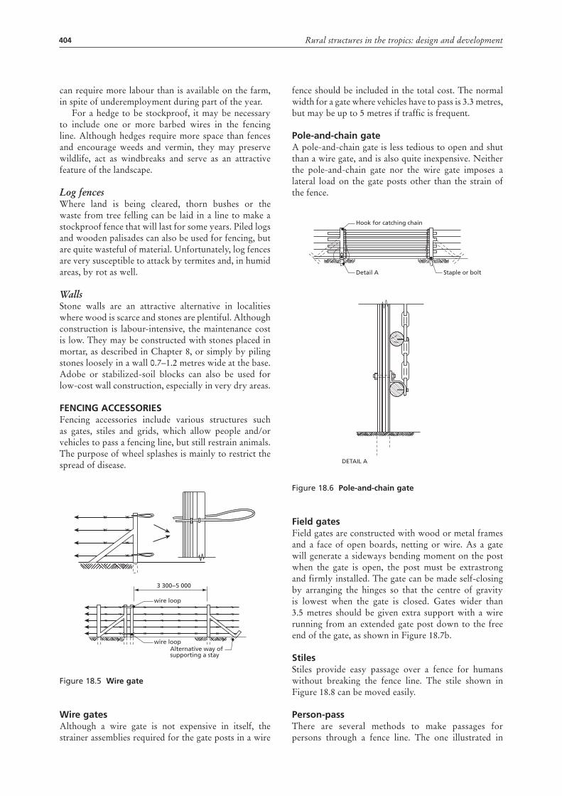
404 Rural structures in the tropics: design and development
can require more labour than is available on the farm, in spite of underemployment during part of the year.
For a hedge to be stockproof, it may be necessary to include one or more barbed wires in the fencing line. Although hedges require more space than fences and encourage weeds and vermin, they may preserve wildlife, act as windbreaks and serve as an attractive feature of the landscape.
Log fencesWhere land is being cleared, thorn bushes or the waste from tree felling can be laid in a line to make a stockproof fence that will last for some years. Piled logs and wooden palisades can also be used for fencing, but are quite wasteful of material. Unfortunately, log fences are very susceptible to attack by termites and, in humid areas, by rot as well.
WallsStone walls are an attractive alternative in localities where wood is scarce and stones are plentiful. Although construction is labour-intensive, the maintenance cost is low. They may be constructed with stones placed in mortar, as described in Chapter 8, or simply by piling stones loosely in a wall 0.7–1.2 metres wide at the base. Adobe or stabilized-soil blocks can also be used for low-cost wall construction, especially in very dry areas.
FEncing accESSoriESFencing accessories include various structures such as gates, stiles and grids, which allow people and/or vehicles to pass a fencing line, but still restrain animals. The purpose of wheel splashes is mainly to restrict the spread of disease.
Figure 18.5 Wire gate
Wire gatesAlthough a wire gate is not expensive in itself, the strainer assemblies required for the gate posts in a wire
3 300−5 000
wire loop
wire loopAlternative way ofsupporting a stay
fence should be included in the total cost. The normal width for a gate where vehicles have to pass is 3.3 metres, but may be up to 5 metres if traffic is frequent.
pole-and-chain gateA pole-and-chain gate is less tedious to open and shut than a wire gate, and is also quite inexpensive. Neither the pole-and-chain gate nor the wire gate imposes a lateral load on the gate posts other than the strain of the fence.
Figure 18.6 pole-and-chain gate
Field gatesField gates are constructed with wood or metal frames and a face of open boards, netting or wire. As a gate will generate a sideways bending moment on the post when the gate is open, the post must be extrastrong and firmly installed. The gate can be made self-closing by arranging the hinges so that the centre of gravity is lowest when the gate is closed. Gates wider than 3.5 metres should be given extra support with a wire running from an extended gate post down to the free end of the gate, as shown in Figure 18.7b.
StilesStiles provide easy passage over a fence for humans without breaking the fence line. The stile shown in Figure 18.8 can be moved easily.
person-passThere are several methods to make passages for persons through a fence line. The one illustrated in
DETAIL A
Hook for catching chain
Detail A Staple or bolt
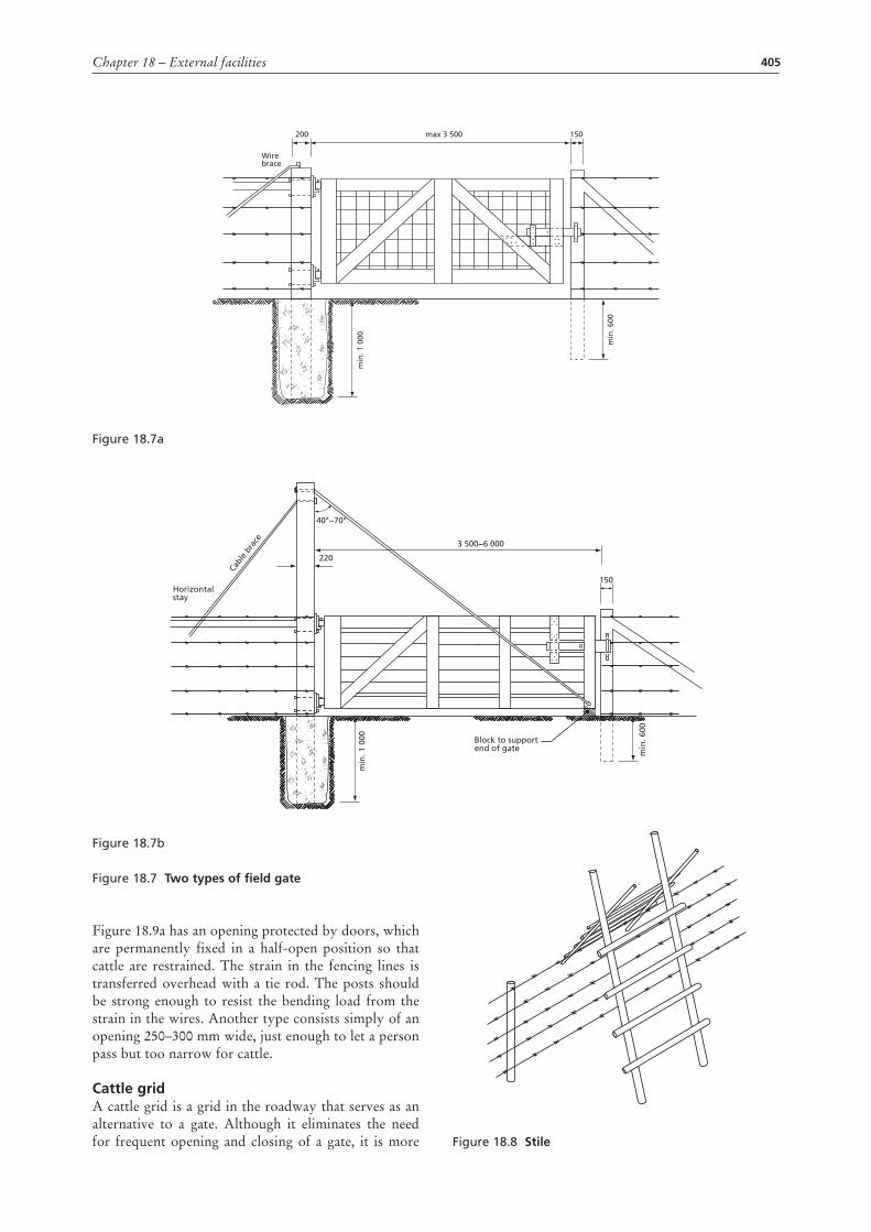
405Chapter 18 – External facilities
Figure 18.9a has an opening protected by doors, which are permanently fixed in a half-open position so that cattle are restrained. The strain in the fencing lines is transferred overhead with a tie rod. The posts should be strong enough to resist the bending load from the strain in the wires. Another type consists simply of an opening 250–300 mm wide, just enough to let a person pass but too narrow for cattle.
cattle gridA cattle grid is a grid in the roadway that serves as an alternative to a gate. Although it eliminates the need for frequent opening and closing of a gate, it is more
Figure 18.7a
Wire brace
max 3 500
min
. 1 0
00
min
. 600
200 150
Figure 18.8 Stile
Figure 18.7b
Figure 18.7 Two types of field gate
Horizontal stay
3 500−6 000
min
. 1 0
00
Cabl
e br
ace
min
. 600
220
40°−70°
Block to supportend of gate
150
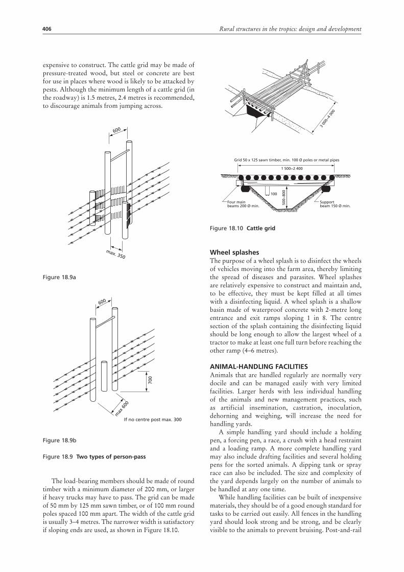
406 Rural structures in the tropics: design and development
expensive to construct. The cattle grid may be made of pressure-treated wood, but steel or concrete are best for use in places where wood is likely to be attacked by pests. Although the minimum length of a cattle grid (in the roadway) is 1.5 metres, 2.4 metres is recommended, to discourage animals from jumping across.
Figure 18.9a
Figure 18.9b
Figure 18.9 Two types of person-pass
The load-bearing members should be made of round timber with a minimum diameter of 200 mm, or larger if heavy trucks may have to pass. The grid can be made of 50 mm by 125 mm sawn timber, or of 100 mm round poles spaced 100 mm apart. The width of the cattle grid is usually 3–4 metres. The narrower width is satisfactory if sloping ends are used, as shown in Figure 18.10.
600
max. 350
600
700
max
600
If no centre post max. 300
Figure 18.10 cattle grid
Wheel splashesThe purpose of a wheel splash is to disinfect the wheels of vehicles moving into the farm area, thereby limiting the spread of diseases and parasites. Wheel splashes are relatively expensive to construct and maintain and, to be effective, they must be kept filled at all times with a disinfecting liquid. A wheel splash is a shallow basin made of waterproof concrete with 2-metre long entrance and exit ramps sloping 1 in 8. The centre section of the splash containing the disinfecting liquid should be long enough to allow the largest wheel of a tractor to make at least one full turn before reaching the other ramp (4–6 metres).
aniMal-hanDling FaciliTiESAnimals that are handled regularly are normally very docile and can be managed easily with very limited facilities. Larger herds with less individual handling of the animals and new management practices, such as artificial insemination, castration, inoculation, dehorning and weighing, will increase the need for handling yards.
A simple handling yard should include a holding pen, a forcing pen, a race, a crush with a head restraint and a loading ramp. A more complete handling yard may also include drafting facilities and several holding pens for the sorted animals. A dipping tank or spray race can also be included. The size and complexity of the yard depends largely on the number of animals to be handled at any one time.
While handling facilities can be built of inexpensive materials, they should be of a good enough standard for tasks to be carried out easily. All fences in the handling yard should look strong and be strong, and be clearly visible to the animals to prevent bruising. Post-and-rail
Grid 50 x 125 sawn timber, min. 100 Ø poles or metal pipes
1 500−2 400
100
Four mainbeams 200 Ø min.
Supportbeam 150 Ø min.
3 00
0−4
000
500−
800
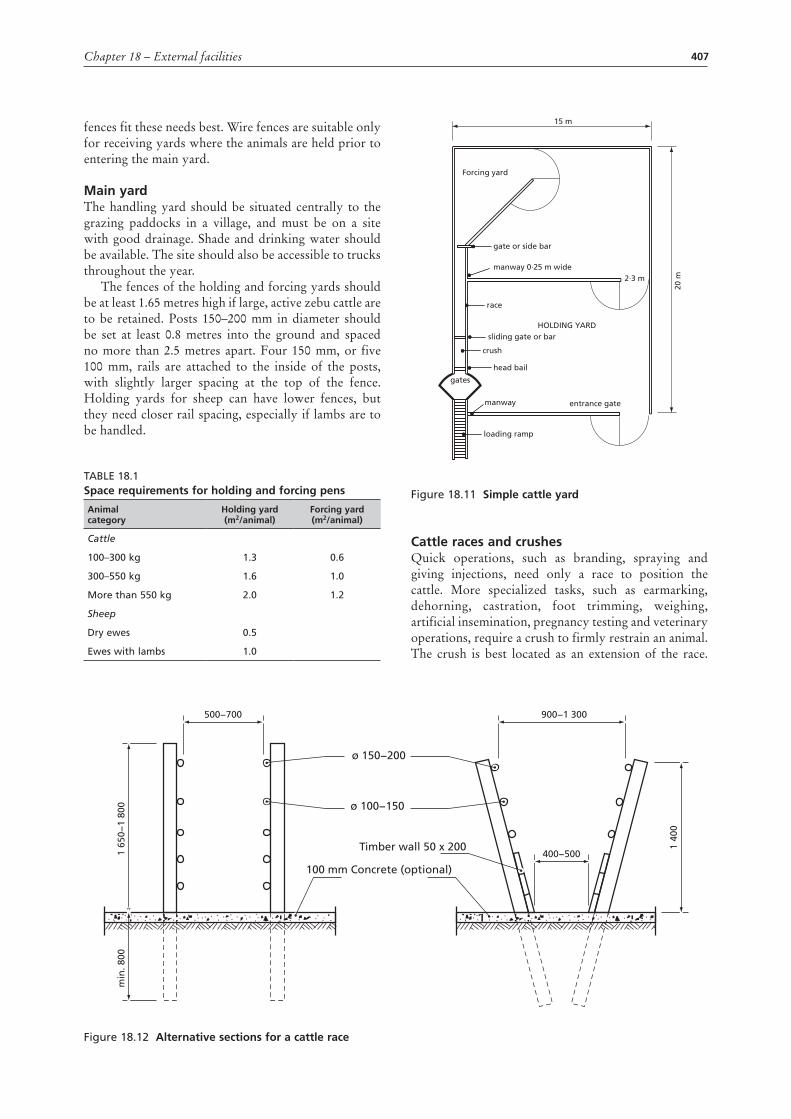
407Chapter 18 – External facilities
fences fit these needs best. Wire fences are suitable only for receiving yards where the animals are held prior to entering the main yard.
Main yardThe handling yard should be situated centrally to the grazing paddocks in a village, and must be on a site with good drainage. Shade and drinking water should be available. The site should also be accessible to trucks throughout the year.
The fences of the holding and forcing yards should be at least 1.65 metres high if large, active zebu cattle are to be retained. Posts 150–200 mm in diameter should be set at least 0.8 metres into the ground and spaced no more than 2.5 metres apart. Four 150 mm, or five 100 mm, rails are attached to the inside of the posts, with slightly larger spacing at the top of the fence. Holding yards for sheep can have lower fences, but they need closer rail spacing, especially if lambs are to be handled.
Table 18.1Space requirements for holding and forcing pens
animal category
holding yard (m2/animal)
Forcing yard (m2/animal)
Cattle
100–300 kg 1.3 0.6
300–550 kg 1.6 1.0
More than 550 kg 2.0 1.2
Sheep
Dry ewes 0.5
ewes with lambs 1.0
Figure 18.11 Simple cattle yard
cattle races and crushesQuick operations, such as branding, spraying and giving injections, need only a race to position the cattle. More specialized tasks, such as earmarking, dehorning, castration, foot trimming, weighing, artificial insemination, pregnancy testing and veterinary operations, require a crush to firmly restrain an animal. The crush is best located as an extension of the race.
15 m
20 m
Forcing yard
gate or side bar
crush
loading ramp
race
gates
head bail
sliding gate or barHOLDING YARD
entrance gate
manway 0∙25 m wide2∙3 m
manway
Figure 18.12 alternative sections for a cattle race
500−700
ø 150−200
ø 100−150
Timber wall 50 x 200
900−1 300
400−5001 65
0−1
800
1 40
0
min
. 800
100 mm Concrete (optional)
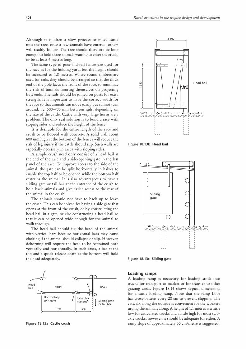
408 Rural structures in the tropics: design and development
Although it is often a slow process to move cattle into the race, once a few animals have entered, others will readily follow. The race should therefore be long enough to hold three animals waiting to enter the crush, or be at least 6 metres long.
The same type of post-and-rail fences are used for the race as for the holding yard, but the height should be increased to 1.8 metres. Where round timbers are used for rails, they should be arranged so that the thick end of the pole faces the front of the race, to minimize the risk of animals injuring themselves on projecting butt ends. The rails should be joined on posts for extra strength. It is important to have the correct width for the race so that animals can move easily but cannot turn around, i.e. 500–700 mm between rails, depending on the size of the cattle. Cattle with very large horns are a problem. The only real solution is to build a race with sloping sides and reduce the height of the fence.
It is desirable for the entire length of the race and crush to be floored with concrete. A solid wall about 600 mm high at the bottom of the fences will reduce the risk of leg injury if the cattle should slip. Such walls are especially necessary in races with sloping sides.
A simple crush need only consist of a head bail at the end of the race and a side-opening gate in the last panel of the race. To improve access to the side of the animal, the gate can be split horizontally in halves to enable the top half to be opened while the bottom half restrains the animal. It is also advantageous to have a sliding gate or tail bar at the entrance of the crush to hold back animals and give easier access to the rear of the animal in the crush.
The animals should not have to back up to leave the crush. This can be solved by having a side gate that opens at the front of the crush, or by constructing the head bail in a gate, or else constructing a head bail so that it can be opened wide enough for the animal to walk through.
The head bail should fix the head of the animal with vertical bars because horizontal bars may cause choking if the animal should collapse or slip. However, dehorning will require the head to be restrained both vertically and horizontally. In such cases, a bar at the top and a quick-release chain at the bottom will hold the head adequately.
Figure 18.13a cattle crush
1 700 650
RACE
Sliding gateor tail bar
lockablemandoor
Horizontallysplit gate
CRUSHHeadbail
Figure 18.13b head bail
Figure 18.13c Sliding gate
loading rampsA loading ramp is necessary for loading stock into trucks for transport to market or for transfer to other grazing areas. Figure 18.14 shows typical dimensions for a cattle loading ramp. Note that the ramp floor has cross-battens every 20 cm to prevent slipping. The catwalk along the outside is convenient for the workers urging the animals along. A height of 1.1 metres is a little low for articulated trucks and a little high for most two-axle trucks, however, it should be adequate for either. A ramp slope of approximately 30 cm/metre is suggested.
1 35
0 Head bail
1 100
Slidinggate
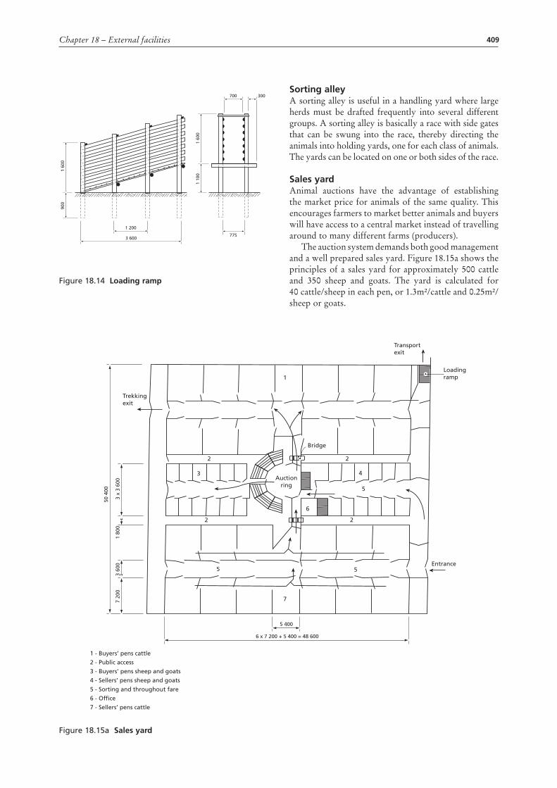
409Chapter 18 – External facilities
Figure 18.14 loading ramp
1 60
090
0
1 60
01
100
1 200
775
700 300
3 600
Sorting alleyA sorting alley is useful in a handling yard where large herds must be drafted frequently into several different groups. A sorting alley is basically a race with side gates that can be swung into the race, thereby directing the animals into holding yards, one for each class of animals. The yards can be located on one or both sides of the race.
Sales yardAnimal auctions have the advantage of establishing the market price for animals of the same quality. This encourages farmers to market better animals and buyers will have access to a central market instead of travelling around to many different farms (producers).
The auction system demands both good management and a well prepared sales yard. Figure 18.15a shows the principles of a sales yard for approximately 500 cattle and 350 sheep and goats. The yard is calculated for 40 cattle/sheep in each pen, or 1.3m²/cattle and 0.25m²/sheep or goats.
Figure 18.15a Sales yard
Transportexit
Loadingramp
Entrance5
5
4
2
1
2
7
5
2 2
6
3
Trekkingexit
Bridge
Auctionring
7 20
0
50 4
00
3 60
01
800
3 x
3 60
0
5 400
6 x 7 200 + 5 400 = 48 600
1 - Buyers’ pens cattle
2 - Public access
3 - Buyers’ pens sheep and goats
4 - Sellers’ pens sheep and goats
5 - Sorting and throughout fare
6 - Office
7 - Sellers’ pens cattle
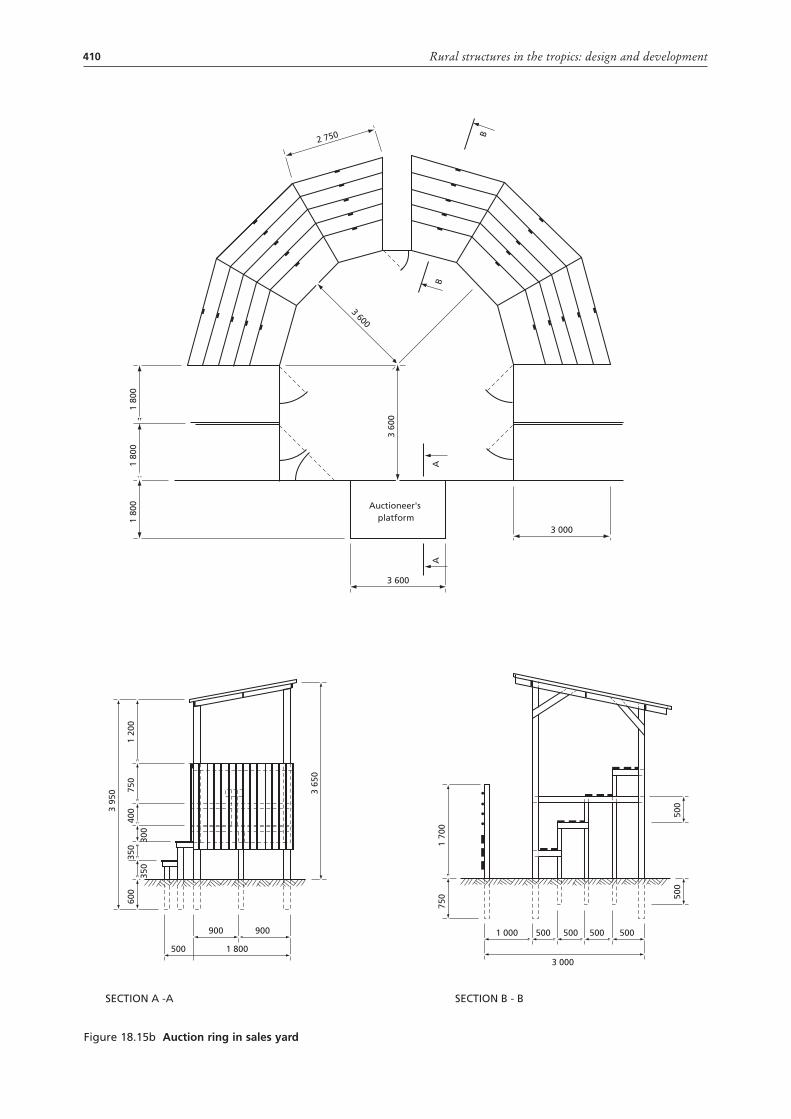
410 Rural structures in the tropics: design and development
Figure 18.15b auction ring in sales yard
1 80
01
800
1 80
01
200
750
4003
950
1 70
075
0
350
300
350
600
3 600
2 750
3 000
3 600
Auctioneer'splatform
AA
3 60
0
B
B
900 900
500 1 800
5005005005001 000
3 000
3 65
0
500
500
SECTION A -A SECTION B - B
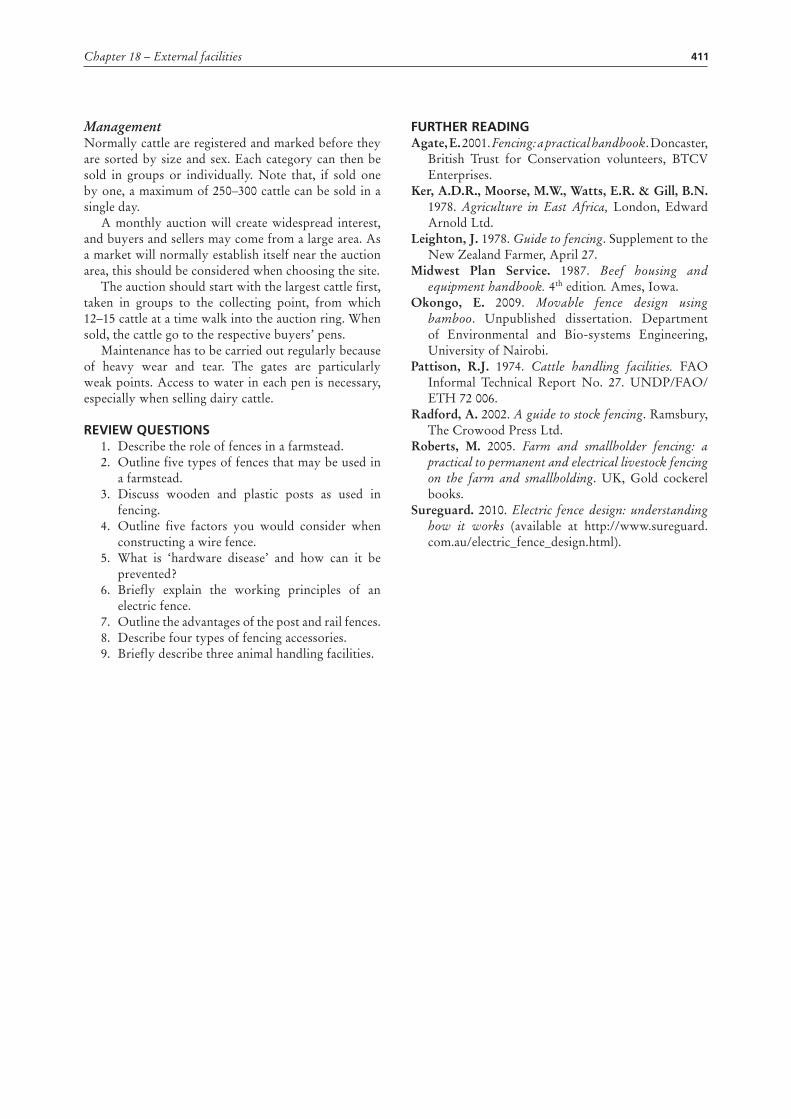
411Chapter 18 – External facilities
ManagementNormally cattle are registered and marked before they are sorted by size and sex. Each category can then be sold in groups or individually. Note that, if sold one by one, a maximum of 250–300 cattle can be sold in a single day.
A monthly auction will create widespread interest, and buyers and sellers may come from a large area. As a market will normally establish itself near the auction area, this should be considered when choosing the site.
The auction should start with the largest cattle first, taken in groups to the collecting point, from which 12–15 cattle at a time walk into the auction ring. When sold, the cattle go to the respective buyers’ pens.
Maintenance has to be carried out regularly because of heavy wear and tear. The gates are particularly weak points. Access to water in each pen is necessary, especially when selling dairy cattle.
rEviEW quESTionS1. Describe the role of fences in a farmstead.2. Outline five types of fences that may be used in
a farmstead.3. Discuss wooden and plastic posts as used in
fencing.4. Outline five factors you would consider when
constructing a wire fence.5. What is ‘hardware disease’ and how can it be
prevented?6. Briefly explain the working principles of an
electric fence.7. Outline the advantages of the post and rail fences.8. Describe four types of fencing accessories.9. Briefly describe three animal handling facilities.
FurThEr rEaDingAgate, E. 2001. Fencing: a practical handbook. Doncaster,
British Trust for Conservation volunteers, BTCV Enterprises.
Ker, A.D.R., Moorse, M.W., Watts, E.R. & Gill, B.N. 1978. Agriculture in East Africa, London, Edward Arnold Ltd.
Leighton, J. 1978. Guide to fencing. Supplement to the New Zealand Farmer, April 27.
Midwest Plan Service. 1987. Beef housing and equipment handbook. 4th edition. Ames, Iowa.
Okongo, E. 2009. Movable fence design using bamboo. Unpublished dissertation. Department of Environmental and Bio-systems Engineering, University of Nairobi.
Pattison, R.J. 1974. Cattle handling facilities. FAO Informal Technical Report No. 27. UNDP/FAO/ETH 72 006.
Radford, A. 2002. A guide to stock fencing. Ramsbury, The Crowood Press Ltd.
Roberts, M. 2005. Farm and smallholder fencing: a practical to permanent and electrical livestock fencing on the farm and smallholding. UK, Gold cockerel books.
Sureguard. 2010. Electric fence design: understanding how it works (available at http://www.sureguard.com.au/electric_fence_design.html).