grain conveyor operator s manual - ag growth …€¦ · will be operating and/or maintaining the...
TRANSCRIPT

GGRAINRAIN C CONVEYORONVEYOR
OOPERATORPERATOR’’SS M MANUALANUAL
1300 1350 1500 1550 1800 1300 1350 1500 1550 1800
20002000
SSERIESERIES C CONVEYORSONVEYORS


SIGN-OFF FORM
Batco Manufacturing Ltd. follows the general Safety Standards specified by the American Society of
Agricultural Engineers (ASAE) and the Occupational Safety and Health Administration (OSHA). Anyone who
will be operating and/or maintaining the Grain conveyor must read and clearly understand ALL Safety,
Operating and Maintenance information presented in this manual.
Do not operate or allow anyone else to operate this equipment until such information has been reviewed.
Annually review this information before the season start-up.
Make these periodic reviews of SAFETY and OPERATION a standard practice for all of your equipment. We
feel that an untrained operator is unqualified to operate this machine.
A sign-off sheet is provided below for your record keeping to show that all personnel who will be working with
the equipment have read and understood the information in the Operator’s Manual and have been instructed in
Date Employee Signature Date Employee Signature

SERIAL NUMBER LOCATION
Always give your dealer the serial number of your Batco Grain conveyor when ordering parts
or requesting service or other information.
The serial number plate is located where indicated. Please mark the number in the space
provided for easy reference.
Serial number locations (Typical)
Model #
Serial #
Production Year

BATCO MANUFACTURING LTD. NEW EQUIPMENT WARRANTY
POLICY:
� Batco Manufacturing Ltd. will warrant each new conveyor to be free from factory
defects in material and workmanship under normal use and service when set up and
operated in accordance with factory instructions.
� Commercial applications will reduce the warranty period to 90 days from the original
date of delivery.
� This warranty will apply under the following conditions:
CONDITIONS:
� The warranty will be limited to one year from the date of purchase.
� A “Warranty Registration Form” and “Inspection Report” must be filled out and
returned to Batco Manufacturing Ltd. at the time of sale in order to qualify for
replacement of defective parts.
� The warranty is void on any unit that has been tampered with or has been subject to
misuse, negligence or accident.
� The warranty is limited to the supplying of replacement parts in exchange for parts
defective due to material or factory workmanship.
� The warranty covers material only, unless expenditures are pre-authorized by Batco
Manufacturing Ltd. in writing.
� A reasonable allowance may be charged to cover labor for replacement of damaged
parts at the discretion of the Batco Warranty Department.
� Normal wear and service items such as belts, hoses, flashing, etc., will only be
considered warranty at the discretion of the Batco Warranty Department.
PROCEDURE:
� All warranty repairs must be performed at an authorized Batco dealership in order to
receive credit.
� All returned parts must be sent to the factory in order to qualify for warranty
replacement.
� All returned parts must be sent to the factory, freight pre-paid, and will be returned
freight collect.
Please direct all claims to the attention of the Warranty Department at Batco Manufacturing Ltd.
(306-773-7779)


1. INTRODUCTION ………………………………………………….. 1.1
2. SAFETY ………………………………………………….. 2.1
2.1 GENERAL SAFETY ………………………………………………….. 2.2
2.2 OPERATING SAFETY ………………………………………………….. 2.3
2.3 PLACEMENT SAFETY ………………………………………………….. 2.3
2.4 MAINTENANCE SAFETY ………………………………………………….. 2.7
2.5 HYDRAULIC SAFETY ………………………………………………….. 2.7
2.6 TRANSPORT SAFETY ………………………………………………….. 2.8
2.7 REFUELING SAFETY ………………………………………………….. 2.8
2.8 STORAGE SAFETY ………………………………………………….. 2.9
2.9 TIRE SAFETY ………………………………………………….. 2.9
………………………………………………….. 2.9
2.11 GAS MOTOR SAFETY ………………………………………………….. 2.9
3. SAFETY SIGNS ………………………………………………….. 3.1
3.1 GENERAL INFORMATION ………………………………………………….. 3.1
3.2 INSTALLATION ………………………………………………….. 3.1
3.3 A-FRAME CONVEYOR DECAL LOCATIONS ………………………………………………….. 3.2
3.3 SCISSOR LIFT CONVEYOR DECAL LOCATIONS ………………………………………………….. 3.3
3.4 SAFETY DECAL LOCATIONS FOR DRIVES ………………………………………………….. 3.4
4. OPERATING AND SAFETY INSTRUCTIONS ………………………………………………….. 4.1
4.1 SAFETY ………………………………………………….. 4.1
4.2 OWNER/OPERATOR RESPONSIBILITY ………………………………………………….. 4.2
4.3 MACHINE COMPONENTS ………………………………………………….. 4.4
4.4 MACHINE BREAK-IN ………………………………………………….. 4.4
4.5 PRE-OPERATION ………………………………………………….. 4.4
4.6 CONTROLS ………………………………………………….. 4.5
4.7 CONVEYOR REPLACEMENT ………………………………………………….. 4.6
4.8 CONVEYOR DRIVE SYSTEM ………………………………………………….. 4.6
4.9 OPERATING INSTRUCTIONS ………………………………………………….. 4.7
4.9.1 STARTING CONVEYOR ………………………………………………….. 4.7
4.9.2 CONVEYOR SHUTDOWN ………………………………………………….. 4.7
4.9.3 EMERGENCY SHUTDOWN ………………………………………………….. 4.7
4.9.4 RE-STARTING (FULL TUBE) ………………………………………………….. 4.7
4.9.5 CONVEYOR OPERATING ANGLES ………………………………………………….. 4.7
4.9.6 BELT SPEED ………………………………………………….. 4.8
4.9.7 OPERATING TIPS ………………………………………………….. 4.8
2.10 BATTERY SAFETY
TABLE OF CONTENTS

4.10 TRANSPORTING SAFELY …………………………………... 4.9
4.10.1 PRE-TRANSPORT CHECKLIST …………………………………... 4.9
4.10.2 TRANSPORT PROCEDURE …………………………………... 4.9
4.11 STORAGE …………………………………... 4.10
5. SERVICE AND MAINTENANCE …………………………………... 5.1
5.1 GENERAL …………………………………... 5.1
5.2 SERVICE …………………………………... 5.1
5.3 SERVICING INTERVALS …………………………………... 5.2
5.4 SERVICE CHECKLIST …………………………………... 5.3
5.5 MAINTENANCE …………………………………... 5.4
5.5.1 CONVEYOR BELT TENSION …………………………………... 5.4
5.5.2 CONVEYING BELT ALIGNMENT …………………………………... 5.6
5.5.3 BELT REPLACING …………………………………... 5.10
5.5.4 CONVEYOR BELT REPLACEMENT …………………………………... 5.10
5.5.5 DRIVE BELT TENSION AND ALIGNMENT …………………………………... 5.11
5.5.6 PTO DRIVE LINE GUARD …………………………………... 5.11
5.5.7 TUBE ALIGNMENT—CABLE TRUSS …………………………………... 5.12
6. TROUBLE SHOOTING …………………………………... 6.1
7. SPECIFICATIONS …………………………………... 7.1
7.1 MECHANICAL …………………………………... 7.1
7.2 BOLT TORQUE …………………………………... 7.5
7.3 HYDRAULIC FITTING TORQUE …………………………………... 7.6
7.3.1 HYDRAULIC PIPE THREAD FITTINGS, NPT …………………………………... 7.6
7.3.2 FOUR BOLT SPLIT FLANGE …………………………………... 7.7
7.3.3 O-RING FITTING, ORB …………………………………... 7.7
7.3.4 FLARE FITTINGS 370, JIC …………………………………... 7.8
7.3.5 HOSE STEM CONNECTIONS …………………………………... 7.9
7.4 MAXIMUM CONTINUOUS FLOW FOR HYD MOTORS …………………………………... 7.10
7.5 CONVEYOR PRODUCT CHART …………………………………... 7.11
TABLE OF CONTENTS
I N T R O D U C T I O N
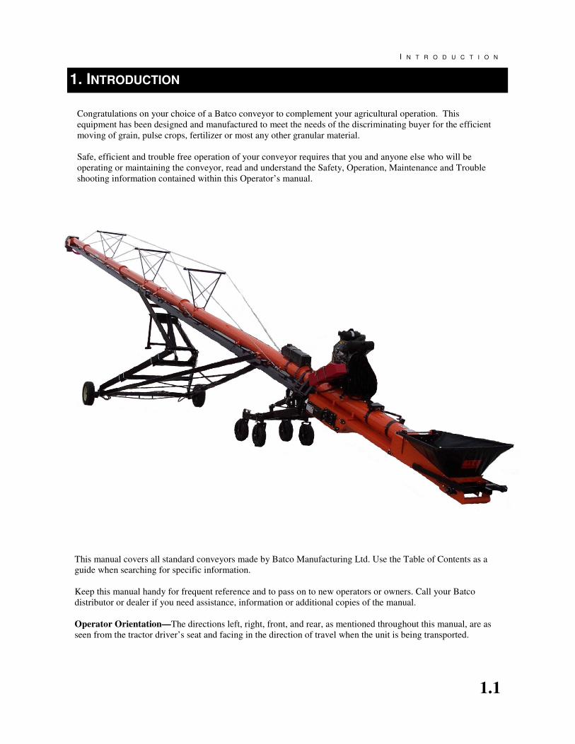
Congratulations on your choice of a Batco conveyor to complement your agricultural operation. This
equipment has been designed and manufactured to meet the needs of the discriminating buyer for the efficient
moving of grain, pulse crops, fertilizer or most any other granular material.
Safe, efficient and trouble free operation of your conveyor requires that you and anyone else who will be
operating or maintaining the conveyor, read and understand the Safety, Operation, Maintenance and Trouble
shooting information contained within this Operator’s manual.
This manual covers all standard conveyors made by Batco Manufacturing Ltd. Use the Table of Contents as a
guide when searching for specific information.
Keep this manual handy for frequent reference and to pass on to new operators or owners. Call your Batco
distributor or dealer if you need assistance, information or additional copies of the manual.
Operator Orientation—The directions left, right, front, and rear, as mentioned throughout this manual, are as
seen from the tractor driver’s seat and facing in the direction of travel when the unit is being transported.
1. INTRODUCTION
1.1

S A F E T Y
2.1
Why is SAFETY important to you?
3 Big Reasons
SIGNAL WORDS:
NOTE THE USE OF SIGNAL
WORDS DANGER, WARNING
CAUTION, AND NOTICE WITH
THE SAFETY MESSAGES. THE
APPROPRIATE SIGNAL WORD
FOR EACH MESSAGE HAS
BEEN SELECTED USING THE
FOLLOWING GUIDELINES:
Accidents Disable and Kill
Accidents Cost $$
Accidents Can Be Avoided
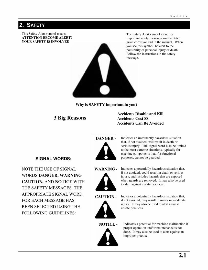
This Safety Alert symbol means:
ATTENTION BECOME ALERT!
YOUR SAFETY IS INVOLVED
The Safety Alert symbol identifies
important safety messages on the Batco
grain conveyor and in the manual. When
you see this symbol, be alert to the
possibility of personal injury or death.
Follow the instructions in the safety
message.
2. SAFETY
DANGER - Indicates an imminently hazardous situation
that, if not avoided, will result in death or
serious injury. This signal word is to be limited
to the most extreme situations, typically for
machine components that, for functional
purposes, cannot be guarded.
WARNING - Indicates a potentially hazardous situation that,
if not avoided, could result in death or serious
injury, and includes hazards that are exposed
when guards are removed. It may also be used
to alert against unsafe practices.
CAUTION - Indicates a potentially hazardous situation that,
if not avoided, may result in minor or moderate
injury. It may also be used to alert against
unsafe practices.
NOTICE - Indicates a potential for machine malfunction if
proper operation and/or maintenance is not
done. It may also be used to alert against an
improper practice.
G R A I N C O N V E Y O R O P E R A T O R ’ S M A N U A L
2.2
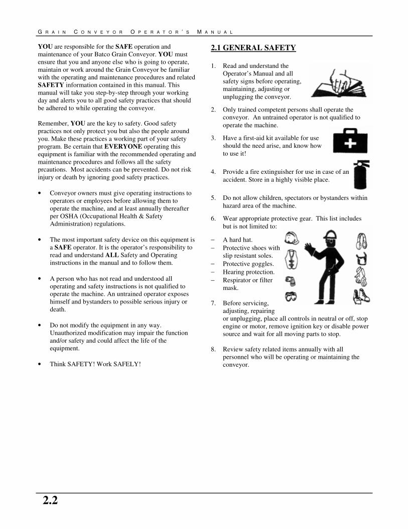
2.1 GENERAL SAFETY
1. Read and understand the
Operator’s Manual and all
safety signs before operating,
maintaining, adjusting or
unplugging the conveyor.
2. Only trained competent persons shall operate the
conveyor. An untrained operator is not qualified to
operate the machine.
3. Have a first-aid kit available for use
should the need arise, and know how
to use it!
4. Provide a fire extinguisher for use in case of an
accident. Store in a highly visible place.
5. Do not allow children, spectators or bystanders within
hazard area of the machine.
6. Wear appropriate protective gear. This list includes
but is not limited to:
− A hard hat.
− Protective shoes with
slip resistant soles.
− Protective goggles.
− Hearing protection.
− Respirator or filter
mask.
7. Before servicing,
adjusting, repairing
or unplugging, place all controls in neutral or off, stop
engine or motor, remove ignition key or disable power
source and wait for all moving parts to stop.
8. Review safety related items annually with all
personnel who will be operating or maintaining the
conveyor.
YOU are responsible for the SAFE operation and
maintenance of your Batco Grain Conveyor. YOU must
ensure that you and anyone else who is going to operate,
maintain or work around the Grain Conveyor be familiar
with the operating and maintenance procedures and related
SAFETY information contained in this manual. This
manual will take you step-by-step through your working
day and alerts you to all good safety practices that should
be adhered to while operating the conveyor.
Remember, YOU are the key to safety. Good safety
practices not only protect you but also the people around
you. Make these practices a working part of your safety
program. Be certain that EVERYONE operating this
equipment is familiar with the recommended operating and
maintenance procedures and follows all the safety
prcautions. Most accidents can be prevented. Do not risk
injury or death by ignoring good safety practices.
• Conveyor owners must give operating instructions to
operators or employees before allowing them to
operate the machine, and at least annually thereafter
per OSHA (Occupational Health & Safety
Administration) regulations.
• The most important safety device on this equipment is
a SAFE operator. It is the operator’s responsibility to
read and understand ALL Safety and Operating
instructions in the manual and to follow them.
• A person who has not read and understood all
operating and safety instructions is not qualified to
operate the machine. An untrained operator exposes
himself and bystanders to possible serious injury or
death.
• Do not modify the equipment in any way.
Unauthorized modification may impair the function
and/or safety and could affect the life of the
equipment.
• Think SAFETY! Work SAFELY!

S A F E T Y
2.3
2.2 OPERATING SAFETY 1. Read and understand the Operator’s Manual and all
safety signs before using.
2. PTO drives: Stop the engine, place all controls in
neutral, set park brake, remove ignition key and wait
for all moving parts to stop before servicing, adjusting,
repairing or unplugging.
3. Hydraulic drives: Stop the engine, place all controls in
neutral, set park brake, remove ignition key and wait
for all moving parts to stop before servicing, adjusting,
repairing or unplugging.
4. Gas engine drives: Stop engine, place all controls in
neutral, remove ignition key and wait for all moving
parts to stop before servicing, adjusting, repairing or
unplugging.
5. Electric motor drives: Disconnect and disable
electrical supply completely and wait for all moving
parts to stop before servicing, adjusting, repairing or
unplugging.
6. Clear the area of bystanders, especially children,
before starting.
7. Be familiar with machine hazard area. If anyone enters
hazard areas, shut down machines immediately. Clear
the area before re-starting.
8. Keep hands, feet, hair and clothing away from all
moving and/or rotating parts.
9. Do not allow riders on the conveyor, tractor or towing
vehicle when transporting.
10. Stay away from overhead obstructions and power lines
during operation and transporting. Electrocution may
occur without direct contact.
11. Do not operate machine when any guards are removed.
12. Set park brake on tractor before starting.
13. Lower conveyor to its lowest position before moving
or transporting or when not in use.
14. Inspect lift cable (if equipped) before using conveyor.
Replace if frayed or damaged.
15. Be sure that conveyor is empty before raising or
lowering.
2.3 PLACEMENT SAFETY 1. Move conveyor only with a tractor/towing vehicle.
Never move by hand. The exception to this would be,
for example, moving a Top Drive Conveyor around in
a yard - as these units are balanced differently.
2. Stay away from overhead power lines when moving
conveyor. Electrocution can occur without direct
contact.
3. Chock conveyor and tractor wheels front and rear
before operating.
4. Keep conveyor as low as possible when moving. Raise
only when it is next to storage facility.
5. Be familiar with the machine hazard area. If anyone
enters hazard area, shut down machine immediately.
Clear the area before restarting.
6. Operate the conveyor on level ground free of debris. If
ground is uneven, anchor the conveyor to prevent
tipping or upending.
When releasing conveyor from the
towing vehicle, test the intake end
for downward weight.
Do not raise the intake end above
drawbar height. Conveyor upend-
ing may occur.
WARNING

G R A I N C O N V E Y O R O P E R A T O R ’ S M A N U A L
2.4
Fig 2.1—Workplace Hazard Area (PTO Drive)
SUPPORT
DISCHARGE END
UNDER CONVEYOR AND
UNDERCARRIAGE AREA
HAZARD—KEEP AWAY
WHEEL CHOCKS
PTO DRIVE AREA
KEEP OUT
CONVEYOR INTAKE AREA
HAZARD—KEEP OUT
OVERHEAD WIRES
KEEP AWAY
WHEEL CHOCKS
WHEEL CHOCKS
WORK AREA
AUTHORIZED
PERSONNEL ONLY
WALKING SURFACE - IS IT SLIPPERY?
ARE THERE THINGS TO TRIP YOU?
KEEP OUT OF SHADED
HAZARD AREA
PTO

S A F E T Y
2.5
Fig 2.2—Workplace Hazard Area (Hydraulic Drive)
KEEP OUT OF SHADED
HAZARD AREA
WORK AREA
AUTHORIZED
PERSONNEL ONLY
WHEEL CHOCKS
WALKING SURFACE - IS IT SLIPPERY?
ARE THERE THINGS TO TRIP YOU?
HYDRAULIC
OVERHEAD WIRES
KEEP AWAY
SUPPORT
DISCHARGE END
UNDER CONVEYOR AND
UNDERCARRIAGE AREA
HAZARD—KEEP AWAY
WHEEL CHOCKS WHEEL CHOCKS
HYDRAULIC DRIVE
AREA KEEP OUT
CONVEYOR INTAKE AREA
HAZARD—KEEP OUT

G R A I N C O N V E Y O R O P E R A T O R ’ S M A N U A L
2.6
Fig 2.3—Workplace Hazard Area (Electric/Gas Drive)
ELEC/GAS
OVERHEAD WIRES
KEEP AWAY
WHEEL CHOCKS WHEEL CHOCKS
SUPPORT
DISCHARGE END
UNDER CONVEYOR AND UNDER-
CARRIAGE AREA HAZARD
KEEP AWAY
CONVEYOR INTAKE AREA
HAZARD—KEEP OUT
CONVEYOR DRIVE AREA
HAZARD—KEEP OUT
WORK AREA
AUTHORIZED
PERSONNEL ONLY
KEEP OUT OF SHADED
HAZARD AREA
S A F E T Y
2.7
2.4 MAINTENANCE SAFETY
1. Review the Operator’s Manual and all safety items
before working with, maintaining or operating the
conveyor.
2. Place all controls in neutral or off, stop engine or
motor, remove ignition key or disable power source
and wait for all moving
parts to stop before
servicing, adjusting,
repairing or unplugging.
3. Follow good shop
practices:
− Keep service area clean &
dry
− Be sure electrical outlets
and tools are properly
grounded.
− Use adequate light for the
job at hand.
4. Before applying pressure to a hydraulic system, make
sure all components are tight and that hoses and
couplings are in good condition.
5. Relieve pressure from hydraulic circuit before
servicing or disconnecting from tractor.
6. Keep hands, feet, hair and clothing away from all
moving and/or rotating parts.
7. Clear the area of bystanders, especially children, when
carrying out any maintenance and repairs or making
any adjustments.
8. Place stands or blocks under the frame before working
beneath the machine.
9. Before resuming work, install and secure all guards
when maintenance work is completed.
10. Support conveyor tube before attempting maintenance
on the undercarriage assembly. Where possible,
conveyor should be in the full down position.
11. Keep safety signs clean. Replace signs that are
damaged or not clearly visible. See chapter 3 for more
information on safety sign locations.
2.5 HYDRAULIC SAFETY
1. Always place all tractor hydraulic controls in neutral
before disconnecting from tractor or working on
hydraulic system.
2. Make sure that all components in the hydraulic system
are kept in good condition and are clean.
3. Replace any worn, cut, abraded, flattened or crimped
hoses.
4. Do not attempt any makeshift repairs to the hydraulic
fittings or hoses by using tape, clamps or cements.
The hydraulic system operates under extremely high-
pressure. Such repairs will fail suddenly and create a
hazardous and unsafe condition.
5. Wear proper hand and eye protection when searching
for a high-pressure hydraulic leak. Use a piece of
wood or cardboard as a backstop instead of hands to
isolate and identify a leak.
6. If injured by a concentrated high-pressure stream of
hydraulic fluid, seek medical attention immediately.
Serious infection or toxic reaction can develop from
hydraulic fluid piercing the skin surface.

G R A I N C O N V E Y O R O P E R A T O R ’ S M A N U A L
2.8
2.6 TRANSPORT SAFETY
1. Read and understand ALL the information in the
Operator’s Manual regarding procedures and Safety
when moving or transporting the conveyor.
2. Check with local authorities regarding transport on
public roads. Obey all applicable laws and
regulations.
3. Always travel at a safe speed. Use caution when
making corners or meeting traffic. Discharge end can
swing dramatically on sharp corners. Ensure you are
clear of obstructions and oncoming traffic.
4. Make sure the SMV (Slow Moving Vehicle) emblem
and all the lights and reflectors that are required by the
local highway and transport authorities are in place,
are clean and can be seen clearly by all overtaking and
oncoming traffic.
5. Do not allow riders on the conveyor or the tractor/
towing vehicle when transporting.
6. Attach conveyor to towing vehicle with a pin and
retainer. Always attach safety chain(s).
7. Fully lower conveyor before transporting.
8. Do not exceed 20 mph (32 km/h). Reduce speed on
rough roads and surfaces.
9. Stay away from overhead obstructions and power lines
when transporting. Electrocution can occur without
direct contact.
10. Always use hazard-warning flashers on tractor/towing
vehicle when transporting unless prohibited by law.
11. Long conveyors have a large turning radius. Allow
ample room for turning, as discharge end may swing
dramatically.
Fig 2.4—Transport Hazard Area
OVER HEAD WIRES
KEEP AWAY
HAZARD
AREA
KEEP OUT

S A F E T Y
2.9
2.7 REFUELING SAFETY
1. Handle fuel with care. It is highly flammable.
2. Shut off engine and allow it to cool for 5 minutes
before refueling. Clean up spilled fuel before
restarting the engine.
3. Do not refuel the machine while smoking or when near
open flame or sparks.
4. Refer to gas engine operators manual for further
details.
2.8 STORAGE SAFETY
1. Store the unit in an area away from human activity.
2. Do not permit children to play on or around the stored
machine.
3. Fully lower conveyor before storing.
2.9 TIRE SAFETY
1. Failure to follow proper procedures when mounting a
tire on a wheel or rim can produce an explosion, which
may result in serious injury or death.
2. Do not attempt to mount a tire unless you have the
proper equipment and experience to do the job.
3. Have a qualified tire dealer or repair service perform
required tire maintenance.
4. When replacing worn tires, make sure they meet the
original tire specifications. Never undersize the
replacement tire.
5. Do not weld to tire rim with the tire mounted on rim.
This action may cause an explosion which could result
in serious injury or death.
2.10 BATTERY SAFETY
1. Wear safety glasses when working near batteries.
2. Keep all sparks and flames away from batteries, as gas
given off by electrolyte is explosive.
3. Avoid contact with battery electrolyte. Wash off any
spilled electrolyte immediately.
4. Do not tip batteries more than 45 degrees, to avoid
electrolyte loss.
5. To avoid injury from sparks or short circuits
disconnect battery ground cable before servicing any
part of an electrical system.
2.11 GAS MOTOR SAFETY
READ AND UNDERSTAND THE OPERATING AND
MAINTENANCE INSTRUCTIONS THAT CAME
WITH YOUR GAS ENGINE.

G R A I N C O N V E Y O R O P E R A T O R ’ S M A N U A L
2.10
This page was intentionally left blank.

3.1
S A F E T Y S I G N S
3. SAFETY SIGNS
3.3 LOCATIONS
The types of safety signs and locations on the equipment
are shown in the illustrations below. Good Safety requires
that you familiarize yourself with the various Safety Signs,
the type of warning and the area, or particular function
related to that area, that requires your SAFETY
AWARENESS.
3.1 GENERAL INFORMATION
1. Keep safety signs clean and legible at all times.
2. Replace safety signs that are missing or have become
illegible.
3. Replaced parts that display a safety sign should also
display the current sign.
4. Safety signs are available from your Distributor or the
factory.
3.2 INSTALLATION
1. Be sure that the installation area is clean and dry.
2. Decide on the exact position before you remove the
backing paper.
3. Align the sign over the specified area and carefully
press the small portion with the exposed sticky
backing in place.
4. Slowly peel back the remaining paper and carefully
smooth the remaining portion of the sign in place.
5. Small air pockets can be pierced with a pin and
smoothed out using the piece of sign backing paper.
REMEMBER: If Safety Signs have been
damaged, removed, become illegible or parts
replaced without safety signs, new signs must
be applied. New safety signs are available from
your authorized dealer.
Fig 3.1—Safety Decal Locations
Part #:P1513002
3.2
G R A I N C O N V E Y O R O P E R A T O R ’ S M A N U A L
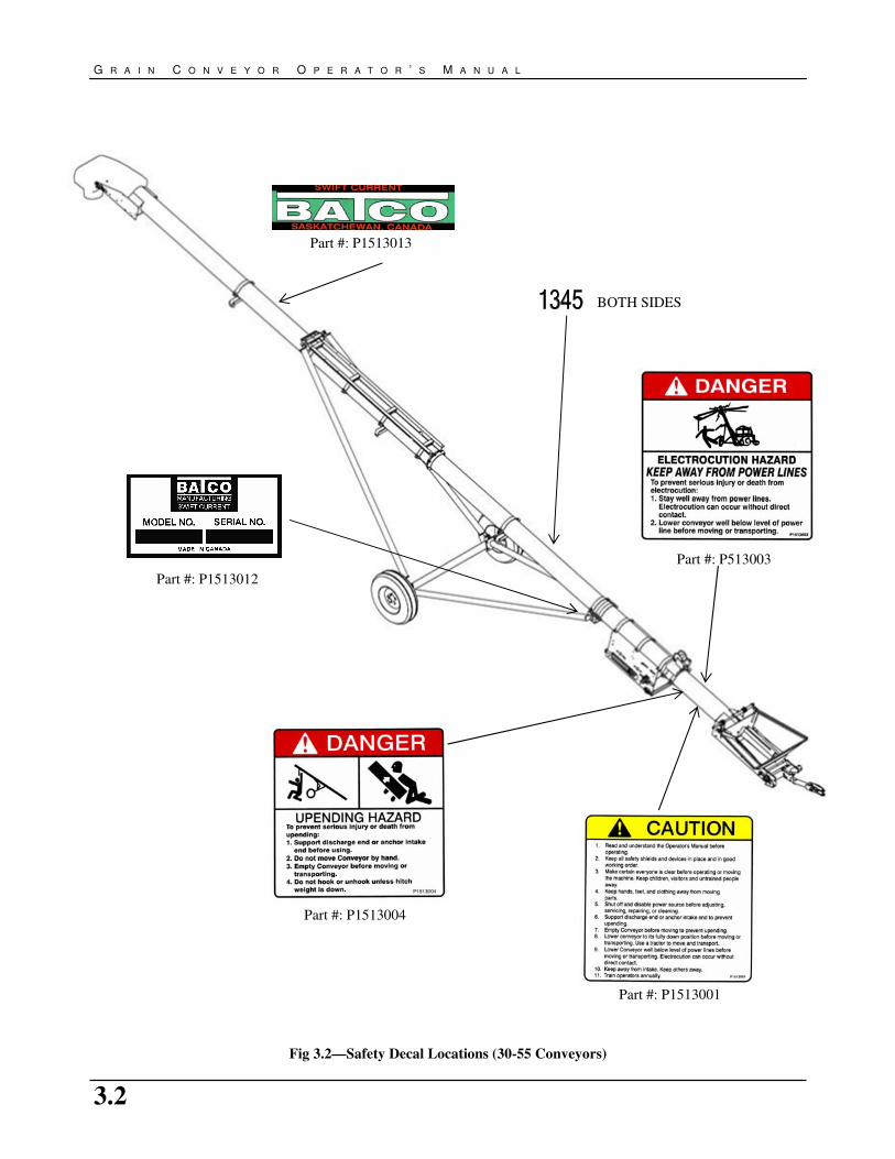
Fig 3.2—Safety Decal Locations (30-55 Conveyors)
Part #: P513003
Part #: P1513004
Part #: P1513001
Part #: P1513012
BOTH SIDES
Part #: P1513013
3.3
S A F E T Y S I G N S
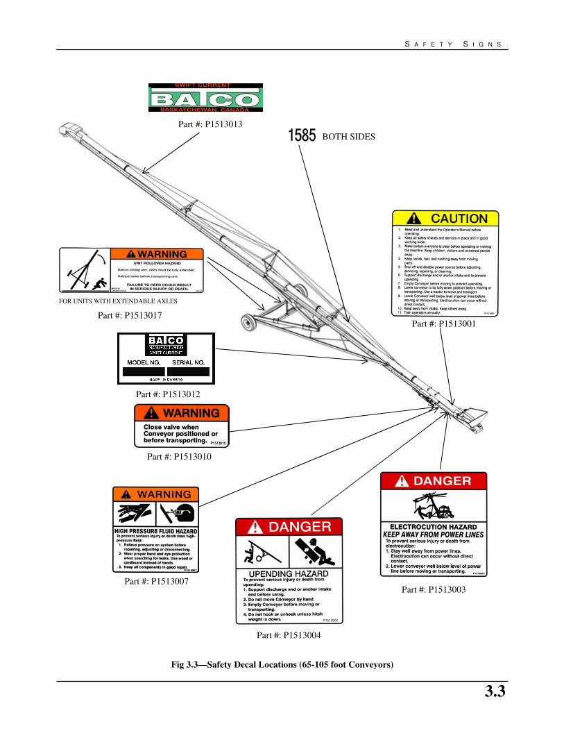
Fig 3.3—Safety Decal Locations (65-105 foot Conveyors)
FOR UNITS WITH EXTENDABLE AXLES
Part #: P1513017
Part #: P1513010
BOTH SIDES
Part #: P1513007
Part #: P1513004
Part #: P1513003
Part #: P1513001
Part #: P1513012
Part #: P1513013

3.4
G R A I N C O N V E Y O R O P E R A T O R ’ S M A N U A L
Fig 3.4—Safety Decal Locations (S-Drive, PTO, Hydraulic & Electric Drives)
Part #: P1513005
Part #: P1513009
Part #: P1513008
Beneath plastic guard
Part #: P1513002
Part #: P1513007
Part #: P1513022
Part #: P1513025 Part #: P1513026

3.5
S A F E T Y S I G N S
Fig 3.5– Safety Decal Locations (Gas Engine & Electric Drives)
Part #: P1513002
Part #: P1513009
Part #: P1513008
Beneath plastic guard
Part #: P1513008
Beneath plastic guard
Part #: P1513002

3.6
G R A I N C O N V E Y O R O P E R A T O R ’ S M A N U A L
This page was intentionally left blank.

4.1
O P E R A T I N G & S A F E T Y I N S T R U C T I O N S
4.1 SAFETY
1. Read and understand the Operator’s Manual and all
safety signs before using.
2. PTO drives: Stop the engine, place all controls in
neutral, set the park brake, remove ignition key and
wait for all moving parts to stop before servicing,
adjusting, repairing or unplugging.
3. Hydraulic drives: Stop the engine, place all controls in
neutral, set park brake, remove ignition key and wait
for all moving parts to stop before servicing, adjusting,
repairing or unplugging.
4. Gas engine drives: Stop engine, place all controls in
neutral, remove ignition key and wait for all moving
parts to stop before servicing, repairing or unplugging.
5. Electric motor drives: Disconnect and disable
electrical supply completely and wait for all moving
parts to stop before servicing, adjusting, repairing or
unplugging.
6. Clear the area of bystanders, especially children,
before starting.
7. Be familiar with machine hazard area. If anyone enters
hazard areas, shut down machine immediately. Clear
the area before restarting.
8. Keep hands, feet, hair and clothing away from all
moving and/or rotating parts.
9. Do not allow riders on the conveyor, tractor or towing
vehicle when transporting.
10. Stay away from overhead obstructions and power lines
during operation and transportation. Electrocution can
occur without direct contact.
11. Do not operate machine when any guards are moved.
12. Set park brake on tractor before starting.
13. Fully lower the conveyor before moving or
transporting or when not in use.
14. Inspect lift cable (if equipped) before using conveyor.
Replace if frayed or damaged.
15. Be sure that conveyor is empty before raising or
lowering.
The Batco Grain conveyor is designed to efficiently move
grain, pulse crops, or granular material between a truck,
trailer or wagon and a storage facility. A tractor PTO,
electric motor, gas engine or hydraulic motor, provides
power. Be familiar with the machine before starting.
It is the responsibility of the owner or operator to read
this manual and to train all other operators before they
start working with the machine. In addition to the
design and configuration of equipment, hazard control
and accident prevention are dependent upon the
awareness, concern and prudence of personnel involved
in the operation, transport, maintenance and storage of
equipment or in the use and maintenance of facilities.
Follow all Safety Instructions exactly. Safety is
everyone’s business. By following recommended
procedures, a safe working environment is provided for
the operator, bystanders and the area around the work
site. Untrained operators are not qualified to operate
the machine.
Many features incorporated into this machine are the result
of suggestions made by customers like you. Read this
manual carefully to learn how to operate the machine
safely and how to set it to provide maximum efficiency. By
following the operating instructions in conjunction with a
good maintenance program, your conveyor will provide
many years of trouble-free service.
4. OPERATING & SAFETY INSTRUCTIONS
4.2 OWNER/OPERATOR RESPONSIBILITY

4.2
G R A I N C O N V E Y O R O P E R A T O R ’ S M A N U A L
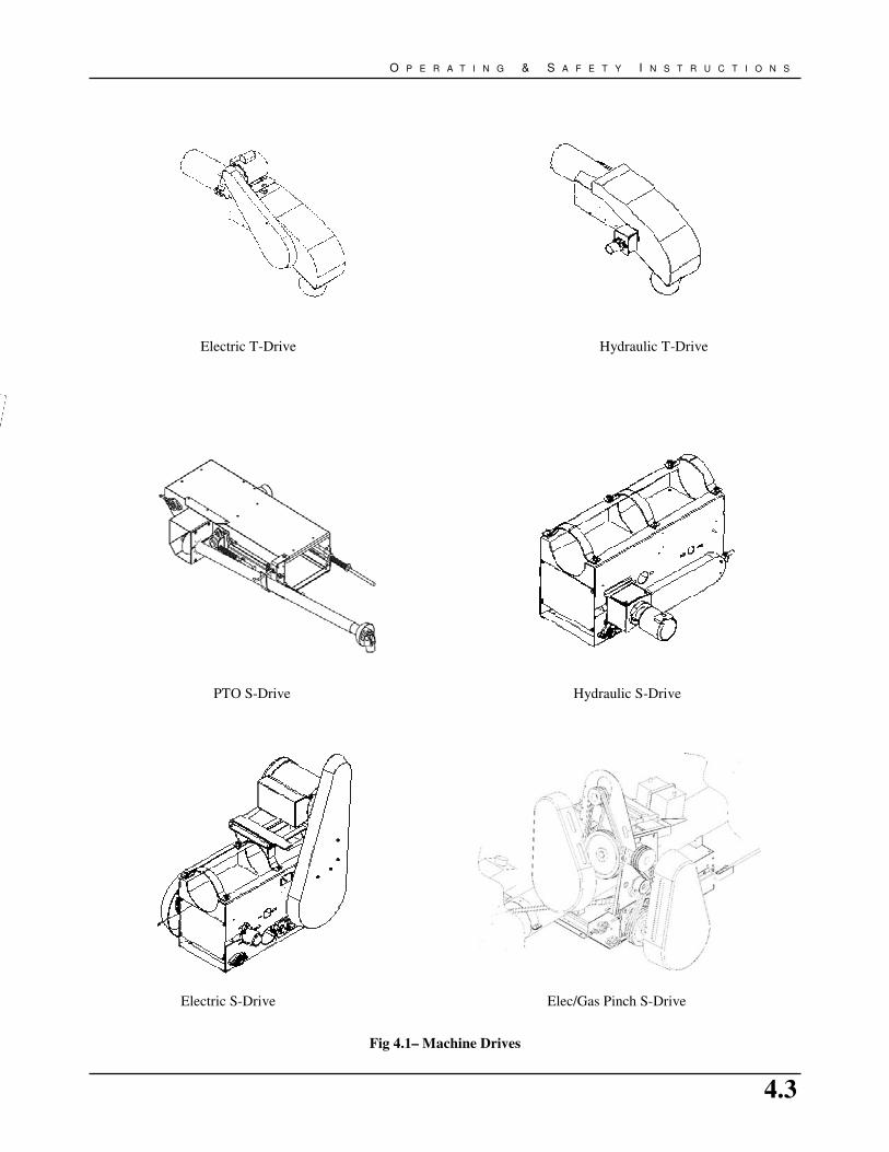
4.3 MACHINE COMPONENTS
The Batco Conveyor is an endless belt that travels through
a tube for moving grain or any granular product. The
machine is portable and can be raised or lowered as
required for loading and unloading of trucks and storage
facilities.
A PTO, gas engine, electric motor or hydraulic motor can
supply power to the s-drive or top drive located under the
tube. Electric and Hydraulic options are available for top
drive units. Material enters the system through a hopper or
intake on the bottom end and exits through the spout or
outlet on the top end. A winch or hydraulic cylinder is used
to raise or lower the conveyor.
Hood
Spout
Main Tube
Truss
S-Drive Hopper
Return Roller or
WG Roller
Scissor Lift or
A-Frame (not shown)
Lift Valve
Axle/Extendable
4.3
O P E R A T I N G & S A F E T Y I N S T R U C T I O N S
Fig 4.1– Machine Drives
PTO S-Drive
Hydraulic T-Drive
Hydraulic S-Drive
Electric T-Drive
Electric S-Drive Elec/Gas Pinch S-Drive

4.4
G R A I N C O N V E Y O R O P E R A T O R ’ S M A N U A L
4.4 MACHINE BREAK-IN
Although there are no operational restrictions on the
conveyor when used for the first time, it is recommended
that the following items be checked:
1. Before starting:
a. Read the conveyor and engine (if so equipped)
Operator’s Manuals.
b. During the first few minutes of operation, check
belt alignment to ensure preset alignment does not
vary under loaded conditions. See Section 5-
Service and Maintenance for further details.
2. After operating or transporting for 1/2 hour:
a. Re-torque all the wheel bolts.
b. Re-torque fasteners and hardware.
c. Check that all safety decals are installed and
legible. Apply new decals if required.
d. Check the drive and conveyor belt tension and
alignment. Tension or align as required.
e. Check that all guards are installed and working as
intended.
3. After operating for 5 and 10 hours:
a. Re-torque all wheel bolts, fasteners and hardware.
b. Check that all guards are installed and are
working properly.
c. Check safety decals. Install new ones if required.
d. Check the drive and conveyor belt tension and
alignment. Tension or align as required.
4.5 PRE-OPERATION CHECKLIST
Efficient and safe operation of the Batco Grain Conveyor
requires that each operator reads and understands the
operating procedures and all related safety precautions
outlined in this section. A pre-operation checklist is
provided for the operator. This checklist is important to
follow for personal safety and maintaining the mechanical
condition of the conveyor.
Before operating the conveyor, and each time thereafter,
the following areas should be checked off:
1. Service the machine per the schedule outlined in
Section 5– Service and Maintenance.
2. Use only a tractor, gas engine or electric motor of
adequate power to operate the machine.
3. Check that all guards are installed, secured and
functioning as intended. Do not operate with missing
or damaged shields.
4. Check work site. Clean up working area to prevent
slipping or tripping.
5. Check winch and cable (if equipped). There should be
at least 3 complete wraps of cable around the winch
drum in transport position. Check cable anchor on
winch drum is tight. Inspect cable and replace if frayed
or damaged.
6. Check that cable clamps are secure.
7. Check that drive and conveying belts are not frayed or
damaged and that they are properly adjusted and
aligned. See Section 5- Service and Maintenance.
8. Be sure wheels are chocked.
9. Check that hopper and spout areas are free of
obstructions.
4.5
O P E R A T I N G & S A F E T Y I N S T R U C T I O N S
4.6 CONTROLS
Before starting operating conveyor, all operators should
familiarize themselves with the location and function of the
controls.
1. GAS ENGINE
Refer to engine operator manual for controls operation.
2. ELECTRIC DRIVE
Use a licensed electrician to provide power to the
machine and to provide convenient shutdown
switches.
3. DIRECT DRIVE (GAS/ELEC)
BELT ENGAGEMENT (if equipped)
Leaver located near hopper allows belt drive to be
engaged or disengaged without cutting power to
engine.
4. WINCH
A winch is located on the top of the tube and is used to
raise and lower the conveyor.
5. HYDRAULIC SAFETY BALL VALVE (scissor-lift
conveyor)
This valve allows oil to flow into or out of the
hydraulic cylinder that raises or lowers the tube. If the
handle is parallel to the hydraulic line the valve is
open. Ensure valve is always closed when machine is
positioned.
6. PTO
Refer to tractor operators manual.
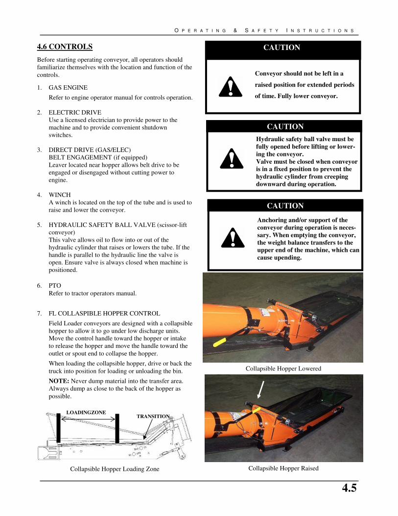
7. FL COLLASPIBLE HOPPER CONTROL
Field Loader conveyors are designed with a collapsible
hopper to allow it to go under low discharge units.
Move the control handle toward the hopper or intake
to release the hopper and move the handle toward the
outlet or spout end to collapse the hopper.
When loading the collapsible hopper, drive or back the
truck into position for loading or unloading the bin.
NOTE: Never dump material into the transfer area.
Always dump as close to the back of the hopper as
possible.
CAUTION
Anchoring and/or support of the
conveyor during operation is neces-
sary. When emptying the conveyor,
the weight balance transfers to the
upper end of the machine, which can
cause upending.
CAUTION
Hydraulic safety ball valve must be
fully opened before lifting or lower-
ing the conveyor.
Valve must be closed when conveyor
is in a fixed position to prevent the
hydraulic cylinder from creeping
downward during operation.
CAUTION
Conveyor should not be left in a
raised position for extended periods
of time. Fully lower conveyor.
Collapsible Hopper Lowered
Collapsible Hopper Raised Collapsible Hopper Loading Zone
LOADINGZONE TRANSITION

4.6
G R A I N C O N V E Y O R O P E R A T O R ’ S M A N U A L
4.7 CONVEYOR PLACEMENT
Follow this procedure when placing the conveyor into its
working position:
1. Clear the area of bystanders, especially children,
before starting.
2. Be sure there is enough clearance from overhead
obstructions and power lines or other equipment
before moving the conveyor.
3. Back the machine up to the storage facility while it is
in its lowered configuration. If equipped with
extendable axles, place in extended position. Use
jack to aid adjustment.
4. Set the park brake on the tractor before dismounting.
5. Use the winch or hydraulic scissor-lift to raise the
machine so it clears the storage facility.
6. Slowly back the machine until the outlet is over the
opening in the storage facility.
7. Use the winch or hydraulics to slowly lower the
machine to the bin. Do not rest the spout or outlet
hood on the bin. This may cause hood or belt
damage.
8. Place chocks in the front and rear of each wheel.
9. Unhook the unit from the tractor or towing vehicle
and lower hopper to the ground.
10. Lower the machine to the bin, but do not rest the
spout or outlet hood on the bin.
11. Disconnect hydraulic hose (if equipped) and close
ball valve.
12. Remove the hitch from the machine to prevent
interfering with other equipment.
13. Review the Workplace Safety Diagram for your
model prior to starting work. Follow all set-up
instruction and do not allow any unauthorized people
into the working area.
14. Check angle of machine. Ensure that the machine
angle is less then the angle of repose of the material
to be moved. See Section 7 for more help.
CAUTION
The machine is closely balanced. Do
not lift unless there is downward
weight on the intake end to prevent
upending.
DANGER
Stay away from overhead power lines.
Electrocution can occur without direct
contact.
4.8 CONVEYOR DRIVE SETUP
1. For the PTO Drive Model:
a. Back the tractor into position.
b. Chock tractor wheels.
c. Attach PTO shaft.
2. For the Hydraulic Drive Model:
a. Back tractor into position.
b. Chock tractor wheels.
c. Plug hydraulic hoses into tractor couplers. Check
flow direction to ensure belt moving forward.
3. For the Electric Motor Model:
a. Have a certified electrician provide power to the
machine.
b. Provide convenient shutdown switches and com-
ply with local electrical codes.
c. Use a totally enclosed electric motor when con-
veying in extremely dusty conditions. Be sure
electric motor is properly grounded.
NOTICE
Attempting to move material at too
steep an angle can result in
excessive slides back and poor
capacity.

4.7
O P E R A T I N G & S A F E T Y I N S T R U C T I O N S
4.9 OPERATING INSTRUCTIONS
When using the conveyor follow this procedure:
1. Clear the area of bystanders, especially small
children, before starting.
2. Review the Section 4.5—Pre-Operation checklist
before starting.
3. Review the Section 2—Workplace Hazards
schematics and use extra care when inside the hazard
area.
4.9.1 Starting Conveyor
I. Electric Drive
1. Turn the electric motor ON.
2. Engage belt drive if equipped
II. Gas Engine Drive
1. Disengage gas engine drive belt or electric
clutch..
2. Move throttle to it 1/4 position for starting.
3. Use choke if required.
4. Start engine.
5. Run engine for a couple of minutes until the
engine warms.
6. Engage belt drive or electric clutch and increase
engine speed to desired speed.
III. PTO Drive
1. Place all controls in neutral.
2. Engage tractor parking brake.
3. Start tractor and run at low idle.
4. Engage PTO and steadily increase engine speed
to desired speed.
IMPORTANT: Position tractor to keep U-joint angles
equal and as small as possible.
IV. Hydraulic Drive Instructions
1. Place all controls in neutral.
2. Start tractor and run at low idle.
3. Engage hydraulic control lever and increase
engine speed to desired speed.
NOTE: The correct operation of hydraulic systems is
directly linked to the pump’s ability to supply the correct
oil flow and pressure. If you cannot obtain the correct belt
speed, check with the dealer to ensure the power unit is
delivering the correct oil volume and pressure.
See Section 7.4 for the required hydraulics for
various motors used.
4.9.2 Conveyor Shutdown
I. PTO Models:
1. Run until the belting is empty.
2. Reduce engine speed to low idle.
3. Disengage PTO clutch.
4. Shut off engine and remove ignition key.
II. Hydraulic Drive Models:
1. Run until the belting is empty.
2. Reduce engine speed to low idle.
3. Place hydraulic control lever in neutral.
4. Shut off engine and remove ignition key.
III. Electric Motor Models:
1. Run until the belting is empty.
2. Disengaged belt drive if equipped.
3. Turn off motor and lock out power source.
IV. Gas Drive Models:
1. Run until the belting is empty.
2. Reduce engine speed to low idle.
3. Disengage belt drive; or disengage electric
clutch if unit is equipped with one.
4. Shut off engine.
4.9.3 Emergency Shutdown
Although it is recommended that the tube be emptied
before stopping, in an emergency situation, stop or shut
down the power source immediately. Lock out all power
and ensure the machine components come to a stop before
inspecting. Correct the emergency before resuming work.
4.9.4 Re-starting (full tube):
When the machine is shut down inadvertently, or for an
emergency, the tube will still be filled with material. Since
the start-up torque loads are much higher than normal when
the tube is full, re-start at low idle engine speed for the
PTO and gas engine models. It may be necessary to
tighten the drive belts slightly to handle the heavier than
normal loads.
4.8
G R A I N C O N V E Y O R O P E R A T O R ’ S M A N U A L
4.9.5 Conveyor Operating Angles
The manual or optional hydraulic lift can set the tube angle
at any position between 12º and 30º when operating.
Because the belt does not have roll back barriers, the
material will roll back if the angle is too steep. Do not
position the conveyor at an angle steeper then the angle of
repose of the material to be moved.
See Section 7 for help on determining these angles.
NOTE: The lower the angle, the greater the capacity.
4.9.6 Belt Speed
The best results are obtained when the input drives are set
to provide a belt speed of 500 to 600 ft/min. on 1300 &
1500 series, 600 to 650 on 1800 & 2000 series.
Count the number of belt revolutions per minute to
determine belt speed. Approximate belt length is double
the length of your machine plus 3 feet. See Section 7.1 for
belt lengths. Use the connector splice as a reference when
counting belt revolutions.
Contact your dealer or the factory for the appropriate drive
components to give the recommended belt speed.
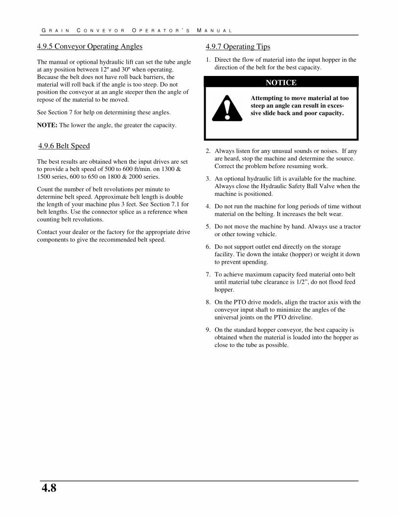
4.9.7 Operating Tips
1. Direct the flow of material into the input hopper in the
direction of the belt for the best capacity.
2. Always listen for any unusual sounds or noises. If any
are heard, stop the machine and determine the source.
Correct the problem before resuming work.
3. An optional hydraulic lift is available for the machine.
Always close the Hydraulic Safety Ball Valve when the
machine is positioned.
4. Do not run the machine for long periods of time without
material on the belting. It increases the belt wear.
5. Do not move the machine by hand. Always use a tractor
or other towing vehicle.
6. Do not support outlet end directly on the storage
facility. Tie down the intake (hopper) or weight it down
to prevent upending.
7. To achieve maximum capacity feed material onto belt
until material tube clearance is 1/2”, do not flood feed
hopper.
8. On the PTO drive models, align the tractor axis with the
conveyor input shaft to minimize the angles of the
universal joints on the PTO driveline.
9. On the standard hopper conveyor, the best capacity is
obtained when the material is loaded into the hopper as
close to the tube as possible.
NOTICE
Attempting to move material at too
steep an angle can result in exces-
sive slide back and poor capacity.

4.9
O P E R A T I N G & S A F E T Y I N S T R U C T I O N S
4.10 TRANSPORTING SAFETY
4.10.1 Pre-Transport Checklist
Before transporting conveyor, ensure that:
1. All bystanders are clear of the machine.
2. Conveyor is in the fully lowered position.
3. Extendable axles are placed in transport position (if
equipped). Use jack to aid adjustment.
4. The hitch pin and safety chain are in place and
secure.
5. On electric motor models, unplug the power cord,
wrap around frame and secure to prevent dragging.
6. On hydraulic powered models, disconnect hydraulic
hoses, remove power source and wrap hose around
frame to prevent dragging.
7. On the PTO drive models, place the driveline in its
stowed position before moving or transporting.
8. For gas drive models shut off fuel supply.
Table 4.1 Speed versus Weight Ratio
Road Speed
Weight or fully equipped
or loaded implement(s)
relative to weight of
towing machine
Up to 32 km/h (20 mph) 1 to 1, or less
Up to 16 km/h (10 mph) 2 to 1, or less
Do not tow if More than 2 - 1
CAUTION
It may be necessary to raise the outlet
end above the storage facility to
provide clearance to raise the intake
end.
DANGER
STAY AWAY FROM OVERHEAD
POWER LINES. ELECTROCUTION
CAN OCCUR WITHOUT DIRECT
CONTACT.
4.10.2 Transport Procedure
1. Check with local authorities regarding conveyor
transport on public roads. Obey all applicable laws
and regulations.
2. Always travel at a safe speed. Use caution when
making corners or meeting traffic.
3. Make sure the SMV (Slow Moving Vehicle) emblem
and all the lights and reflectors that are required by
the local highway and transport authorities are in
place, are clean, and can be seen clearly by all over-
taking and oncoming traffic.
4. Do not allow riders on the conveyor or the tractor
when transporting.
5. Stay away from overhead obstructions and power
lines when transporting. Electrocution can occur
without direct contact.
6. Always use hazard-warning flashers on tractor or
towing vehicle when transporting, unless prohibited
by law.
7. Never go across slopes of more than 11º. It is better
to go straight up or straight down the slope.
8. It is not recommended that the machine be trans-
ported faster than 20 mph (32 km/h). Table 4.1 refer-
ences the acceptable transport speed as per the ratio
of tractor weight versus conveyor weight. See Sec-
tion 7 for conveyor weights.
9. Long conveyors have a large turning radius. Allow
ample room for turning, as discharge end may swing
dramatically.
10. Use caution when moving conveyors over rolling
terrain. In severe dips the discharge end may contact
the ground.

4.10
G R A I N C O N V E Y O R O P E R A T O R ’ S M A N U A L
4.11 STORAGE
To protect the conveyor in storage you should:
1. Lower the conveyor to its lowest position for storage.
2. Store the unit in an area away from human activity.
3. Select an area that is dry, level and free of debris.
4. Do not permit children to play on or around the stored
machine.
5. Remove all residual material from the conveyor.
6. Stop machine so that the belt lacing is inside the tube.
This protects the lacing from weathering.
7. Wash the entire machine thoroughly using a water
hose or pressure washer to remove all dirt, mud, debris
or residue.
8. Inspect all hydraulic hoses, fittings, lines, couplers and
valves. Tighten any loose fittings. Replace any fitting
or hose if damaged.
9. Touch up all paint nicks and scratches to prevent
rusting.
10. If machine is not equipped with belt weather guards,
position it in such a way as to limit wind exposure to
the belt.
11. Place a block under the jack to ensure it will not freeze
to the ground in the winter.
To prepare the conveyor for use after storage, you should:
1. Check tire pressure and add air if required. See tire for
inflation pressure details.
2. Replace any damaged parts or safety decals.
3. Conduce general maintenance. See Section 5-Service
and Maintenance for further details.
4. Inspect lift cable (if equipped) and replace cable if
damaged.
5. Inspect all hydraulic components. Replace all damaged
or loose components.
DANGER
Watch for overhead electrical wires.
Stay away from overhead power lines.
Electrocution can occur without direct
contact.
CAUTION
Support conveyor discharge end before
removing or replacing any parts on the
undercarriage.
5.1
S E R V I C E & M A I N T E N A N C E I N S T R U C T I O N S
5.1 GENERAL
1. Review the Operator’s Manual and all safety items
before working with, maintaining or operating the
conveyor.
2. Place all controls in neutral or off position, stop the
engine, remove ignition key or disable power source
and wait for all moving parts to stop before servicing,
adjusting, repairing or unplugging.
3. Follow good shop practices:
a. Keep service area clean and dry.
b. Be sure electrical outlets and tools are properly
grounded.
c. Use adequate light for the job at hand.
4. Before applying pressure from hydraulic system, make
sure all components are tight and that hoses and
couplings are in good condition.
5. Relieve pressure from hydraulic circuit before
servicing or disconnecting from tractor.
6. Keep hands, feet, hair and clothing away from all
moving and/or rotating parts.
7. Clear the area of bystanders, especially children, when
carrying out any maintenance and repairs or making
adjustments.
8. Place stands or blocks under the frame before working
beneath the machine.
9. Before resuming work, install and secure all guards
when maintenance work is completed.
10. Support conveyor tube before attempting maintenance
on the under carriage assembly. Where possible,
conveyor should be in the full down position.
11. Keep safety signs clean. Replace any signs that are
damaged or not visible.
5.2 SERVICE
1. FLUIDS AND LUBRICANTS
a. Grease:
Use SAE multi-purpose high temperature grease
with extreme pressure (EP) performance. Also
acceptable is SAE multi-purpose lithium based
grease.
b. Engine crankcase oil:
See engine operators manual for details.
c. Engine Gasoline:
See engine operators manual for details.
d. Storing Lubricants:
Your machine can operate at top efficiency only if
clean lubricants are used. Use clean containers to
handle all lubricants. Store them in an area
protected from dust, moisture and other
contaminants.
2. GREASING
NOTE: Most original equipment bearings used
by Batco are sealed units and will not accept
grease.
a. Wipe grease fitting with a clean cloth before
greasing to avoid injecting dirt and grit.
b. Replace and repair broken fittings immediately.
c. If fittings will not take grease, remove and clean
thoroughly. Also clean lubricant passageway.
Replace fitting if necessary.
5. SERVICE & MAINTENANCE
Use the Maintenance Checklist provided to keep a record
of all scheduled maintenance
(See Section 5.4-Service Checklist).

5.2
G R A I N C O N V E Y O R O P E R A T O R ’ S M A N U A L
5.3 SERVICING INTERVALS
Initial start up servicing: As the belt alignment is preset to
run true under a condition of no load, it is important to
check alignment and make adjustments if required during
the initial few minutes of loaded operation.
1. 8 Hours or Daily
• Check the conveyor belt tension and alignment.
(See Section 5.5.1-2).
PTO Drive Models
• Grease all grease fittings at 8 - 10 hour intervals.
• Inspect U-Joint for wear.
• Ensure PTO shaft to spline connection is secure.
• Inspect guards and ensure they are in good condition
and are free to rotate.
Gas Engine Drive Models
• Check fuel level. Add as required.
• Check gearbox oil level.
• Check crankcases oil level. Add as required.
• Check drive belt tension and alignment.
• Check wet kit oil reservoir level is equipped.
Refer to gas engine operator manual for further detail.
Electric Drive Models
• Check drive belt tension and alignment.
• Check gearbox oil level.
2. 40 Hours or Weekly
• Check the conveying belt tension and alignment.
(See Section 5.5.1-2).
• Check condition of hopper flashing. Be sure it seals
the hopper and prevents grain leakage.
• Look for hydraulic leaks and repair if required.
• Clean engine air filter (if equipped).
3. 200 Hours or Annually
• Check for tube straightness. Adjust cables if re-
quired. (See Section 5.5.7).
• Check roller bearings for wear. Any rollers making
noise, getting hot while running, or that have play
should be replaced.
• Re-pack wheel bearings.
• Wash machine.
• Check gearbox oil level.
• Inspect roller lagging. If showing signs of wear.
• Check belt lacing. If any clips are worn through,
replace ALL lacing.
• Check hopper flashing for wear. Worn flashing will
cause hopper leakage. Replace any worn flashing.
CAUTION
OPERATING THE CONVEYOR
WITH A DAMAGED ROLLER
WILL RESULT IN A DAMAGED
CONVEYOR BELT.

5.3
S E R V I C E & M A I N T E N A N C E I N S T R U C T I O N S
5.4 SERVICE CHECKLIST
See Lubrication and Maintenance sections for details of service. Photocopy this page to continue record keeping.
ACTION CODES: ����=Check CL=Clean R=Re-pack L=Lubricate C=Change
40 HOURS OR WEEKLY Week 1 2 3 4 5 6 7 8 9 10 11 12 13 14 15 16 17 18 19 20 21 22
� � � � Belt Tension & Alignment
� � � � Conveyor Belt Tracking
� � � � Condition of Hopper Flashing
� � � � Check for Hydraulic Leaks
Electric Drive Models
� � � � Drive Belt Tens. & Alignment
Gas Engine Drive Models
� � � � Drive Belt Tens. & Alignment
CL Air Cleaner Foam
8 HOUR OR DAILY DAY 1 2 3 4 5 6 7 8 9 10 11 12 13 14 15 16 17 18 18 20 21 22
� � � � Conveyor Belt Tracking
L PTO Shaft (3)
� � � � Fuel & Oil Level(s)
Day 23 24 25 26 27 28 29 30 31 32 33 34 35 36 37 38 39 40 41 42 43 44
� � � � Conveyor Belt Tracking
L PTO Shaft (3)
� � � � Fuel & Oil Level(s)
Day 45 46 47 48 49 50 51 52 53 54 55 56 57 58 59 60 61 62 63 64 65 66
� � � � Conveyor Belt Tracking
L PTO Shaft (3)
� � � � Fuel & Oil Level(s)
Day 67 68 69 70 71 72 73 74 75 76 77 78 79 80 81 82 83 84 85 86 87 88
� � � � Conveyor Belt Tracking
L PTO Shaft (3)
� � � � Fuel & Oil Level(s)
200 HOURS OR ANNUAL YEAR 1 YEAR 2 YEAR 3 YEAR 1 YEAR 2 YEAR 3
� � � � Tube Straightness � � � � Belt Lacing
� � � � Roller Bearings � � � � Hopper Flashing
R Wheel Bearings Hydraulic Drive Models
CL Machine L Roller Chain-Input Coupler
� � � � Gearbox Oil Level Gas Engine Drive Models
� � � � Roller Lagging C Engine Oil

5.4
G R A I N C O N V E Y O R O P E R A T O R ’ S M A N U A L
Table 5.1 - BELT TENSION INSTRUCTIONS
Note: Refer to Figures 5.7-5.12 for illustrations.
Description
Steps For Conveyor Type
Top
Drive S-Drive
S-Drive
w/springs
Pinch
S-Drive
Clear bystanders. 1 1 1 1
Remove ignition key or lockout power source. 2 2 2 2
Remove guards if necessary. 3 3 3 3
** Loosen bearing bolts and jam nut (if included) at tightener roller (see Figure 5.5). 4
Tighten take-up roller bolts so that springs compressed. If springs are already properly
compressed then tighten the take-up bolts 1”, ensure equal (see Figure 5.6).
4
Tighten take-up bolts 1”, ensure equal (see Figure 5.6). 4
Check to ensure pinch roller is moveable. Spring tension should measure 4”. 4
Tighten tightener bolts equally, use tape to verify (see Figure 5.5). Belt should deflect
1-2” when pushed down with a 5lb force or be difficult to pull from sides of hopper
transition.
5 5
Tighten bearing bolts and jam nut (if included). 6
Check belt tension by running conveyor for one minute. If belt is not slipping, then pro-
ceed to next step, otherwise repeat from step **. 7 5 5 6
Check takeup springs under startup. Springs should not come loose under startup. If
they do, start machine more softly and increase takeup tension slightly. The takeup
spring must not be tensioned more than the pinch spring or slippling will result.
7
If belt is not slipping, but now running to one side, the tensioned roller needs to be re-
aligned, See Belt Alignment section that follows. 8 6 6 8
Replace guards if removed. 9 7 7 9
Pinch Top
Drive
1
2
3
4
5
6
7
8
9
10
5.5 MAINTENANCE
By following a careful service and maintenance program
for your machine, you will enjoy many years of trouble-
free service.
5.5.1 CONVEYOR BELT TENSION
Adjusting your conveyor belt for proper tension helps to
ensure trouble-free operation and long belt life. A conveyor
belt only needs to be tight enough to not slip on the drive
roller. If the belt is too loose, it will slip on the drive roller
making a noticeable sound, slowing the belt down. To cor-
rect belt slippage and set proper tension in the belt, follow
the steps in Table 5.1 below. Depending on the type of
conveyor you have, you will want to follow the steps for
the Conveyor Type in the table. Only the steps that apply
are numbered.
Helpful Tips:
• If belt is slipping and adjustment bolts are fully tight-
ened, then belt must be shortened. See Section 5.5.4 –
Belt Replacing for further details.
• Belt should not be easy to pull from the hopper transi-
tion sides, otherwise the belt will require tensioning.
Table 5.2- RECOMMENDED SPRING LENGTHS
Conveyor
Spring Compressed
Length ‘B’ (See Fig 5.6)
1300 Series Match to Indicator
1500 Series Match to Indicator
2000 Series 5"
WARNING
ENSURE IGNITION KEY IS RE-
MOVED OR LOCKOUT POWER-
SOURCE BEFORE ADJUSTING
OR SERVICING CONVEYOR
IMPORTANT: Do not operate conveyor if belt is slip-
ping. Stop conveyor and tighten belt. Failure to do so will
damage the belt and may void the warranty.
NOTE: Some belts may have uneven edges, appearing
misaligned. Wait until the belt makes a complete revolu-
tion before adjusting rollers.
• When conveyor is starting/operating, the belt stretches
and the spring extends to take-up the stretched belt.
See Table 5.2 for recommended spring compression.
Excessive droop between s-drive and hopper should be
corrected.

5.5
S E R V I C E & M A I N T E N A N C E I N S T R U C T I O N S
TAKE UP BOLT
Figure 5.6 - S-DRIVE
JAM NUT TIGHTENER BOLT BEARING BOLT
CAUTION
TAKEUP SPRINGS MUST NOT
BE TENSIONED MORE THAN
THE PINCH SPRINGS OR SLIP-
PAGE MAY RESULT
Figure 5.7 - PINCH TOP DRIVE
Figure 5.5 - HOPPER
PINCH SPRING
ROLLER
5.6
G R A I N C O N V E Y O R O P E R A T O R ’ S M A N U A L
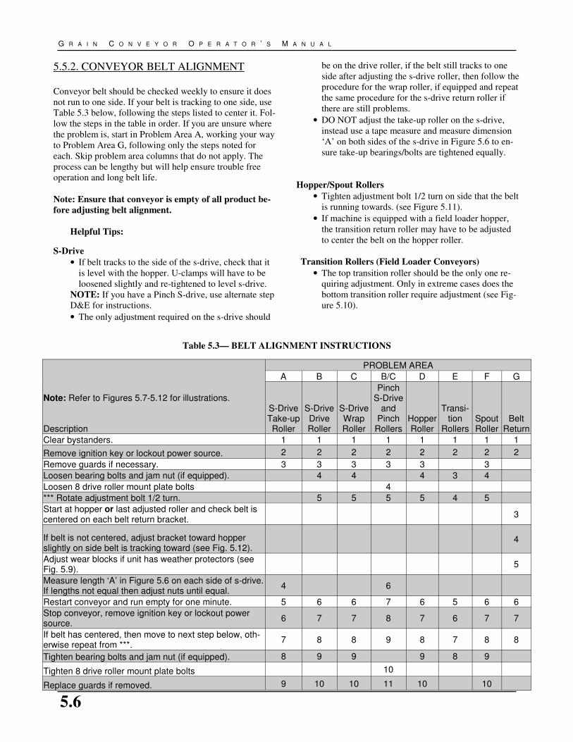
5.5.2. CONVEYOR BELT ALIGNMENT
Conveyor belt should be checked weekly to ensure it does
not run to one side. If your belt is tracking to one side, use
Table 5.3 below, following the steps listed to center it. Fol-
low the steps in the table in order. If you are unsure where
the problem is, start in Problem Area A, working your way
to Problem Area G, following only the steps noted for
each. Skip problem area columns that do not apply. The
process can be lengthy but will help ensure trouble free
operation and long belt life.
Note: Ensure that conveyor is empty of all product be-
fore adjusting belt alignment.
Helpful Tips:
S-Drive
• If belt tracks to the side of the s-drive, check that it
is level with the hopper. U-clamps will have to be
loosened slightly and re-tightened to level s-drive.
NOTE: If you have a Pinch S-drive, use alternate step
D&E for instructions.
• The only adjustment required on the s-drive should
be on the drive roller, if the belt still tracks to one
side after adjusting the s-drive roller, then follow the
procedure for the wrap roller, if equipped and repeat
the same procedure for the s-drive return roller if
there are still problems.
• DO NOT adjust the take-up roller on the s-drive,
instead use a tape measure and measure dimension
‘A’ on both sides of the s-drive in Figure 5.6 to en-
sure take-up bearings/bolts are tightened equally.
Hopper/Spout Rollers
• Tighten adjustment bolt 1/2 turn on side that the belt
is running towards. (see Figure 5.11).
• If machine is equipped with a field loader hopper,
the transition return roller may have to be adjusted
to center the belt on the hopper roller.
Transition Rollers (Field Loader Conveyors)
• The top transition roller should be the only one re-
quiring adjustment. Only in extreme cases does the
bottom transition roller require adjustment (see Fig-
ure 5.10).
Note: Refer to Figures 5.7-5.12 for illustrations.
Description
PROBLEM AREA
A B C B/C D E F G
S-Drive
Take-up
Roller
S-Drive
Drive
Roller
S-Drive
Wrap
Roller
Pinch
S-Drive
and
Pinch
Rollers
Hopper
Roller
Transi-
tion
Rollers
Spout
Roller
Belt
Return
Clear bystanders. 1 1 1 1 1 1 1 1
Remove ignition key or lockout power source. 2 2 2 2 2 2 2 2
Remove guards if necessary. 3 3 3 3 3 3
Loosen bearing bolts and jam nut (if equipped). 4 4 4 3 4
Loosen 8 drive roller mount plate bolts 4
*** Rotate adjustment bolt 1/2 turn. 5 5 5 5 4 5
Start at hopper or last adjusted roller and check belt is
centered on each belt return bracket. 3
If belt is not centered, adjust bracket toward hopper
slightly on side belt is tracking toward (see Fig. 5.12).
4
Adjust wear blocks if unit has weather protectors (see
Fig. 5.9). 5
Measure length ‘A’ in Figure 5.6 on each side of s-drive.
If lengths not equal then adjust nuts until equal. 4 6
Restart conveyor and run empty for one minute. 5 6 6 7 6 5 6 6
Stop conveyor, remove ignition key or lockout power
source. 6 7 7 8 7 6 7 7
If belt has centered, then move to next step below, oth-
erwise repeat from ***. 7 8 8 9 8 7 8 8
Tighten bearing bolts and jam nut (if equipped). 8 9 9 9 8 9
Tighten 8 drive roller mount plate bolts 10
Replace guards if removed. 9 10 10 11 10 10
Table 5.3— BELT ALIGNMENT INSTRUCTIONS
5.7
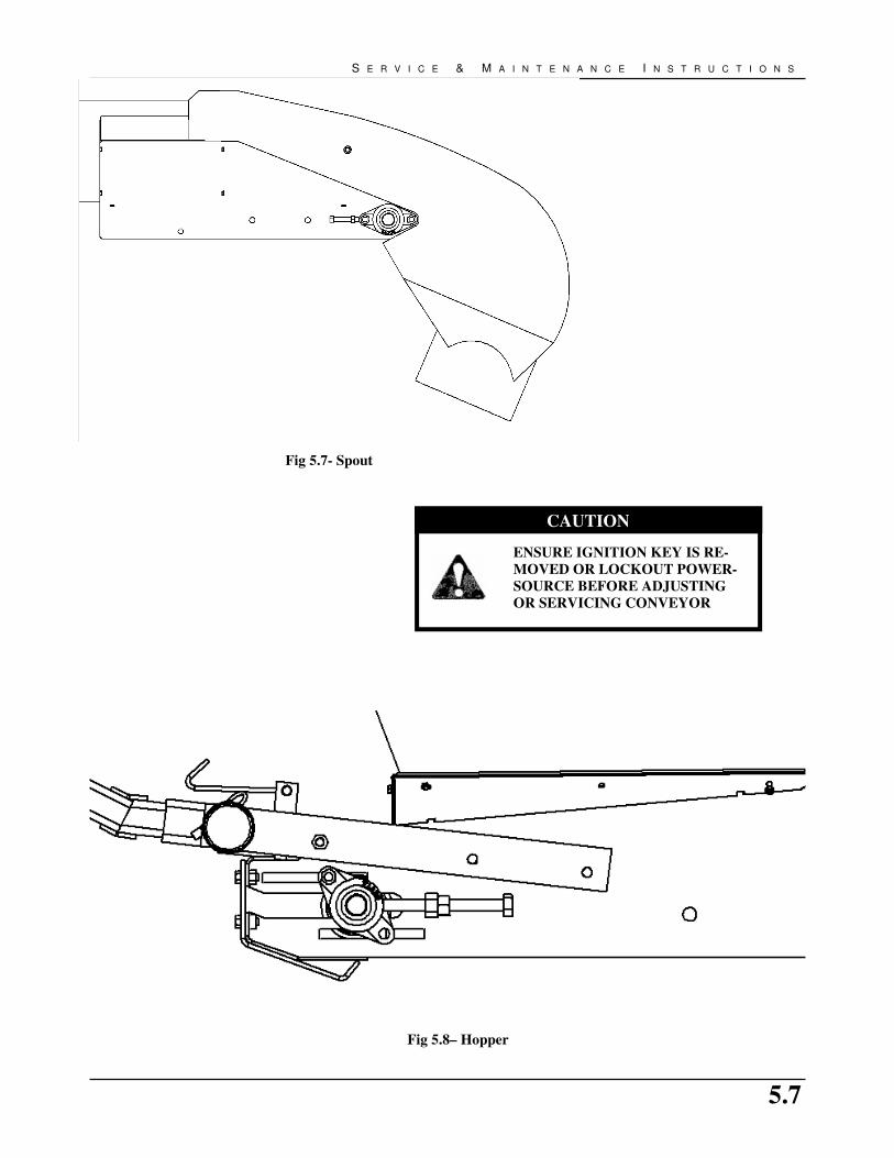
S E R V I C E & M A I N T E N A N C E I N S T R U C T I O N S
CAUTION
ENSURE IGNITION KEY IS RE-
MOVED OR LOCKOUT POWER-
SOURCE BEFORE ADJUSTING
OR SERVICING CONVEYOR
Fig 5.8– Hopper
Fig 5.7- Spout
5.8
G R A I N C O N V E Y O R O P E R A T O R ’ S M A N U A L
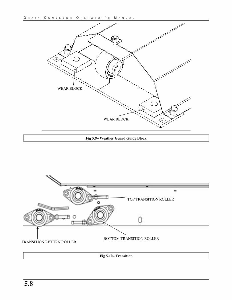
Fig 5.9– Weather Guard Guide Block
Fig 5.10– Transition
BOTTOM TRANSITION ROLLER
TOP TRANSITION ROLLER
WEAR BLOCK
WEAR BLOCK
TRANSITION RETURN ROLLER

5.9
S E R V I C E & M A I N T E N A N C E I N S T R U C T I O N S
Fig 5.11- BELT TRACKING ON ROLLERS
Fig 5.12- BELT TRACKING ON RETURN ROLLER
BELT
ROLLER
TIGHTEN
ADJUSTMENT
SCREW
BELT TRACKING
LOOSEN
ADJUSTMENT
SCREW
BELT TRACKING
TAP BRACKET
THIS
DIRECTION
RETURN
ROLLER
BRACKET
TUBE
SPOUT
HOPPER
BELT

5.10
G R A I N C O N V E Y O R O P E R A T O R ’ S M A N U A L
5.5.4 CONVEYOR BELT REPLACEMENT
1. Rotate the belting until the lacing is by the hopper or
easily accessible.
2. Move the tension roller to its loosest position.
3. Pull all the slack to the lacing area.
4. Remove the lacing pin (see Figure 5.14).
5. Attach one end of the replacement belt to the belt end
being removed, closest to the hopper.
6. Pull the old belt out and the new belt will be threaded
into place.
7. Disconnect the old belt.
8. Reattach conveyor belt ends together. If required, use a
ratchet strap clamped to both end of belt to cinch belt-
ing ends together.
9. Install lacing pin and crimp retainer clips onto each
end of the lacing pin.
10. Remove ratchet strap and tighten conveyor belt (see
Section 5.4.1-Conveyor Belt Tension).
11. Check and set belting alignment (see Section 5.4.2-
Belt Alignment).
12. Clear area of all bystanders and engage conveyor
drive. Allow to run for 30 seconds then shut down
conveyor and inspect lacing.
Fig 5.13- S-DRIVE BELT PATH
5.5.3 BELT RELACING
1. Rotate the belting until the lacing is by the hopper or
easily accessible.
2. Loosen conveyor belt and remove lacing retainer clip
and pin.
3. Use a square and sharp knife and cut lacing off right
behind the lacing clips. MUST ensure that cut belt has
a square end.
4. Use knife to cut Chevron pattern off 1 inch back from
end of belt. This ensures that the lacing is centered and
fully seated on the belt.
5. Use lacing tool to install new lacing clips. Lacing clips
are one clip shorter than belt width. For example: the
lacing for a 15 inch wide belt is 14 clips. Center lacing
on belt and install lacing as per instructions on lacing
tool.
6. Reattach conveyor belt ends together. If required, use a
ratchet strap clamped to both ends of belt to cinch belt-
ing ends together.
7. Install lacing pin and crimp retainer clips onto each
end of the lacing pin.
8. Remove ratchet strap and tighten conveyor belt (see
Section 5.4.1-Conveyor Belt Tension).
9. Check and set belting alignment (see Section 5.4.2-
Belt Alignment).
10. Clear area of all bystanders and engage conveyor
drive. Allow to run for 30 seconds then shut down
conveyor and inspect lacing.
Fig 5.14- BELT LACING PIN
RETAINER CLIP

5.11
S E R V I C E & M A I N T E N A N C E I N S T R U C T I O N S
5.5.5 DRIVE BELT TENSION & ALIGNMENT
Power to the conveyor is transmitted through a set of V belts.
The drive system must be maintained at the proper belt
tension and pulley alignment to obtain the desired
performance and life. When maintaining the belt drive
system for the electric drive model, follow this procedure:
1. Turn motor off and unplug power cord or turn off power
at the master panel before starting on drive belt systems.
2. Belt Tension (Gas/Electric Drive):
a. Push on the center of the belt span with a force of
approximately 5 lbs.
b. The belts will deflect approximately 1/4” to 1/2”
when properly tensioned.
c. Move the motor base to set drive belt tension.
d. Close and secure guards.
3. Alignment:
a. Lay a straight edge across the pulley faces to
check the alignment.
b. Use the pulley hub to move the pulley to the
required position for alignment.
c. Tighten hub bolts to secure pulley on shaft.
d. Check belt tension.
e. Close and secure guards.
4. Belt Replacement:
a. Move motor base to its loosest position.
b. Remove old belts and replace with new one.
c. Check pulley alignment. Adjust if required.
d. Close and secure guards.
5.5.6 PTO DRIVE LINE GUARD
The shield must turn freely on the PTO shaft. Daily
lubrication of both shield bearings and periodic cleaning
will ensure safe operation of the shield.
If the shield is damaged or worn, replace the components.

5.12
G R A I N C O N V E Y O R O P E R A T O R ’ S M A N U A L
5.5.7 TUBE ALIGNMENT CABLE TRUSS
1. Loosen cable clamps on trusses.
2. Support spout end of unit.
3. Starting from the outermost cables and working your
way in, tighten cable eyebolts evenly on both sides
until the spout just starts to bow upward (See Figure
5.15).
• The tube should not deflect to the left or right if
tightened evenly.
• When material is conveyed, the tube may deflect
down.
• Tension should be greater on longer cables than on
shorter cables. If the conveyor tubes remain
straight then the cables are tensioned properly.
4. Tighten cable clamps on trusses.
5. Secure jam nut on cable eyebolt.
Fig 5.15– CABLE TRUSS ASSEMBLY

6.1
T R O U B L E S H O O T I N G
The Batco grain conveyor uses an endless flat belt moving through a tube to convey material from one location to
another. It is a simple and reliable system that requires minimal maintenance.
In the following section, we have listed many of the problems, causes, and solutions to the problems that you may
encounter.
If you encounter a problem that is difficult to solve, even after having read through this troubleshooting section, please
call your local Batco dealer or distributor. Before you call, please have this Operator’s Manual and the serial number
from your machine ready.
6. TROUBLE SHOOTING
OVERALL
Problem Cause Solution
Low conveying capacity Conveyor angle is too high Reposition with lower tube angle (see
section 7.3)
Incorrect belt speed Verify and adjust belt speed to appro-
priate speed (see section 4)
Conveyor belt slipping See belt slipping
Drive belts slipping See belt slipping
Low capacity for some grains Smaller and smoother grains will slide
at shallower angles
See low conveying capacity
BELT
Problem Cause Solution
Belt slipping Conveying belt loose Tighten and align belt (see section 5)
Drive roller lagging worn or damaged Replace drive roller lagging
Drive belts loose Tighten and align (see section 5)
Belt frozen to tube from operating in
high humidity in cold conditions
Remove conveyor from area of high
humidity and warm belt to de-ice
Excessive belt edge fraying Belt not aligned Align and tension belt (see section 5)
Belt loose Belt stretches over time Re-tension belt (see section 5)
Can also be caused by oily grain/
product
If tightener is fully engaged you may
need to shorten belt
HOPPER
Problem Cause Solution
Grain leaking from conveyor
hopper
Belt not tracked (centered) Track belt (see section 5)
Flashing installed incorrectly or worn Inspect flashing for wear and replace if
required
Hopper cloth wor or damaged Replace damaged hopper cloth
Hopper cloth collapsing under
grain
Misaligned or broken spring(s) Check spring installation and repair as
required
Pivot shafts improperly installed On some machines switching pivot
shafts left to right will increase hopper
tension
TUBE
Problem Cause Solution
Conveyor Tube appears curved or
sags
Support cables tightened unevenly Align cables (see section 5)
Transition filler rings are worn or need
replacement.
Adjust transition filler rings, replace if
worn.

6.2
G R A I N C O N V E Y O R O P E R A T O R ’ S M A N U A L
DRIVE
Problem Look For Solution
Drive making noise Slipping belt See belt slipping
Hot shaft, pulley or bearing Overheated components indicate a
failed bearing that must be repaired
Broken drive roller Replace damaged component
SPOUT
Problem Cause Solution
Grain leaking from conveyor
spout between belt and tube
Belt not tracked (centered) Track belt (see section 5)
Grain leaking from conveyor
spout between hood and belt
Belt speed is too fast, hood plugging Decrease belt speed or feed rate
FRAME
Problem Cause Solution
Scissor lift not lifting conveyor Ball valve on lift line closed Open ball valve
Inadequate hydraulic pressure from
source
Use alternate hydraulic pressure
source. Contact your local dealer for
Conveyor lifts slowly Inadequate hydraulic pressure from
source
Use alternate hydraulic pressure
source. Contact your local dealer for
If conveyor lowers faster than it lifts
then the check valve may be installed
in opposite direction
Lower machine to transport position
and inspect check valve. Re-install in
opposite direction if required. See
indicator arrow on valve
Machine will lift but not lower Foreign object clogging check valve Contact your local dealer for assistance
Conveyor will not stay elevated
(Scissor)
Ball valve not closed while in elevated
position
Close ball valve
Leaking hydraulic hose or fitting Lower machine to transport position
and repair leaks as required
Leaking seal in hydraulic cylinder Lower machine to transport position
and repair hydraulic cylinder as re-
Conveyor will not stay elevated
(A-frame)
Faulty winch Lower machine to transport position
and repair or replace winch
Faulty cable Lower machine to transport position
and repair or replace cable
Conveyor makes noise while lift-
ing
Frame parts loose and move while lift-
ing
Replace damaged components and re-
tension frame fasteners
Lift cylinder discharges oil from
breather while lifting
If machine lifts, this is just captured oil
in the top of cylinder
Cleanup oil spill and continue opera-
tion as normal
If machine will not lift, seal in hydrau-
lic cylinder is damaged
Lower machine to transport position
and repair hydraulic cylinder as re-
BRACKETS
Problem Cause Solution
U-clamps sliding on tube Clamp not properly crimped to tube Contact your local dealer for correct
positioning

7.1
S P E C I F I C A T I O N S
7.1 MECHANICAL 1300 SERIES
7. SPECIFICATIONS
UP
- O
PE
RA
TIO
N
DO
WN
- T
RA
NS
PO
RT
MO
DE
L #
BE
LT
LE
NG
TH
TO
TA
L
WE
IGH
T
A
B
AN
GL
E
C
B
AN
GL
E
LE
NG
TH
W
IDT
H
HP
PT
O
HP
EL
EC
H
P G
AS
HP
HY
D
(CU
.IN
.)
1300 S
ER
IES
1314LP
28' 4"
526
- -
- 2.5
5.5
21.0
14.3
3.0
n/a
5.0
6.5
4.5
(H
)
SW
ING
TR
AN
SF
ER
35' 0"
571
n/a
n/a
n/a
n/a
n/a
n/a
n/a
n/a
n/a
5.0
n/a
5.9
(H
)
1330 T
OP
DR
IVE
58' 8"
1209
14.0
10.7
31.0
5.8
12.9
10.0
n/a
7.5
n/a
5.0
n/a
5.9
(H
)
1335 T
OP
DR
IVE
68' 8"
1306
17.5
11.1
32.0
10.9
12.2
17.0
n/a
7.5
n/a
5.0
n/a
5.9
(H
)
1340 T
OP
DR
IVE
78' 8"
1403
20.1
14.2
33.0
11.9
15.1
16.0
n/a
7.5
n/a
7.5
n/a
5.9
(H
)
1345 T
OP
DR
IVE
88' 8"
1500
21.4
18.3
30.0
12.2
19.0
15.0
n/a
7.5
n/a
7.5
n/a
5.9
(H
)
1350 T
OP
DR
IVE
98' 8"
1607
23.3
17.8
30.0
11.5
19.8
13.0
n/a
7.5
n/a
7.5
n/a
5.9
(H
)
1335 T
DF
L
76' 4"
1627
17.1
13.8
30.0
12.0
14.9
20.0
n/a
7.5
25.0
7.5
24.0
14.9
(2000)
1345 T
DF
L
96' 4"
1813
22.1
19.9
30.0
13.4
19.9
16.0
n/a
7.5
25.0
7.5
24.0
14.9
(2000)
1335 F
L S
-Drive
80' 4"
1631
17.9
17.2
30.0
10.1
19.6
14.7
n/a
7.5
25.0
7.5
24.0
14.9
(2000)
1345 F
L S
-Drive
100' 4"
1817
22.6
23.4
30.0
12.6
25.7
15.5
n/a
7.5
25.0
7.5
24.0
14.9
(2000)
1335
72' 8"
1500
15.5
15.5
29.0
10.9
16.3
17.0
n/a
7.5
25.0
5.0
20.0
14.9
(2000)
1340
82' 8"
1541
16.5
10.8
31.0
9.8
11.6
15.0
n/a
7.5
25.0
7.5
20.0
14.9
(2000)
1345
92' 8"
1590
21.5
19.5
30.0
12.5
21.3
15.0
n/a
7.5
25.0
7.5
20.0
14.9
(2000)
1355
112' 10"
2144
26.2
22.1
30.0
14.1
24.6
14.0
n/a
10.3
30.0
7.5
24.0
14.9
(2000)
NO
TE
: A
LL
AN
GL
ES
AN
D M
EA
SU
RE
ME
NT
S
SH
OW
N A
RE
MA
CH
INE
LIM
ITS
. T
HE
MA
X O
P-
ER
AT
ION
AN
GL
E D
EP
EN
DS
ON
TH
E P
RO
DU
CT
BE
ING
CO
NV
EY
ED
, U
SU
AL
LY
LE
SS
TH
AN
30
DE
G.

7.2
G R A I N C O N V E Y O R O P E R A T O R ’ S M A N U A L
1500 SERIES
MO
DE
L #
B
EL
T
LE
NG
TH
TO
TA
L
WE
IGH
T
UP
—O
PE
RA
TIO
N
HP
PT
O
HP
EL
EC
H
P G
AS
HP
HY
D
(CU
.IN
.)
1500 S
ER
IES
A
B
A
NG
LE
C
B
A
NG
LE
L
EN
GT
H
WID
TH
1515
30' 8"
642
- -
- 2.7
6.4
19.0
17.8
3.8
n/a
5.0
9.0
5.9
(H
)
SW
ING
TR
AN
SF
ER
34' 6"
700
n/a
n/a
n/a
n/a
n/a
n/a
n/a
n/a
n/a
n/a
n/a
5.9
(H
)
1530 T
OP
DR
IVE
60' 8"
1283
13.9
11.5
29.0
9.0
13.1
15.0
n/a
7.5
n/a
7.5
n/a
5.9
(H
)
1535 T
OP
DR
IVE
70' 8"
1382
17.5
12.0
31.0
11.0
12.9
16.0
n/a
7.5
n/a
7.5
n/a
5.9
(H
)
1540 T
OP
DR
IVE
80' 8"
1481
18.8
15.2
29.0
9.6
15.7
12.0
n/a
7.5
n/a
7.5
n/a
5.9
(H
)
1545 T
OP
DR
IVE
90' 8"
1580
19.3
19.2
26.0
11.9
19.6
14.0
n/a
7.5
n/a
7.5
n/a
5.9
(H
)
1550 T
OP
DR
IVE
100' 8"
1689
n/a
n/a
n/a
n/a
n/a
n/a
n/a
7.5
n/a
7.5
n/a
5.9
(H
)
1535 T
DF
L
80' 5"
1755
18.0
15.4
30.0
11.6
16.9
18.0
n/a
7.5
25.0
7.5
24.0
14.9
(2000)
1545 T
DF
L
100' 5"
2081
22.9
21.1
30.0
13.9
21.8
16.5
n/a
7.5
25.0
7.5
24.0
14.9
(2000)
1535 F
L S
-Drive
85'
1761
17.9
17.2
30.0
10.1
19.6
14.7
n/a
7.5
25.0
7.5
24.0
14.9
(2000)
1545 F
L S
-Drive
105'
2087
22.6
23.4
30.0
12.6
25.7
15.5
n/a
7.5
25.0
7.5
24.0
14.9
(2000)
1535
74' 3"
1577
15.4
16.3
28.0
10.7
16.9
16.0
n/a
7.5
25.0
7.5
20.0
14.9
(2000)
1540
84' 3"
1620
n/a
n/a
n/a
n/a
n/a
n/a
n/a
7.5
25.0
7.5
20.0
14.9
(2000)
1545
94' 3"
1671
21.3
20.4
29.0
12.2
21.9
14.0
n/a
7.5
25.0
7.5
20.0
14.9
(2000)
1550
105' 6"
2087
26.1
28.8
30.0
14.1
26.0
15.0
n/a
10.3
30.0
10.0
24.0
14.9
(2000)
1555
115' 6"
2230
26.1
28.8
30.0
14.1
26.0
15.0
n/a
10.3
30.0
10.0
24.0
14.9
(2000)
1565
135' 3"
2506
33.6
22.4
32.0
11.6
26.1
9.0
n/a
11.0
30.0
15.0
27.0
n/a
1575
155' 0"
2784
39.0
30.9
32.0
12.6
36.1
8.0
n/a
11.0
40.0
20.0
30.0
n/a
1585
175' 0"
3138
43.2
35.2
31.0
14.2
41.7
9.0
n/a
11.3
/14.6
40.0
20.0
35.0
n/a
1590
185' 0"
3587
45.8
39.5
31.0
14.9
46.7
9.0
n/a
11.3
/14.6
40.0
20.0
35.0
n/a
15100
205' 0"
4162
49.5
39.7
30.0
13.5
48.3
7.4
n/a
11.3
/14.6
40.0
20.0
35.0
n/a
DO
WN
—T
RA
NS
PO
RT
NO
TE
: A
LL
AN
GL
ES
AN
D M
EA
SU
RE
ME
NT
S
SH
OW
N A
RE
MA
CH
INE
LIM
ITS
. T
HE
MA
X O
P-
ER
AT
ION
AN
GL
E D
EP
EN
DS
ON
TH
E P
RO
DU
CT
BE
ING
CO
NV
EY
ED
, U
SU
AL
LY
LE
SS
TH
AN
30
DE
G.
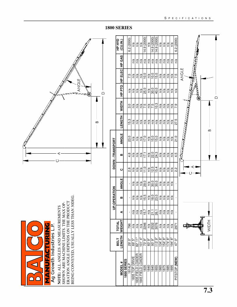
7.3
S P E C I F I C A T I O N S
1800 SERIES
BE
LT
LE
NG
TH
TO
TA
L
WE
IGH
T
UP
-OP
ER
AT
ION
MO
DE
L #
A
B
A
NG
LE
C
B
A
NG
LE
L
EN
GT
H
WID
TH
H
P P
TO
H
P E
LE
C
HP
GA
S
HP
HY
D
(CU
.IN
.)
1800 S
ER
IES
1814LP
29' 0"
796
- -
- 2.8
4.8
23.0
15.3
3.0
n/a
7.5
6.2
(2000)
1835 T
OP
DR
IVE
69' 5"
n/a
n/a
n/a
n/a
n/a
n/a
n/a
n/a
n/a
n/a
n/a
n/a
n/a
1835 F
IELD
LO
AD
ER
82' 11"
n/a
n/a
n/a
n/a
n/a
n/a
n/a
n/a
n/a
n/a
n/a
n/a
n/a
1845 F
IELD
LO
AD
ER
101' 4"
n/a
n/a
n/a
n/a
n/a
n/a
n/a
n/a
n/a
n/a
n/a
n/a
n/a
1835
73' 9"
2246
15.7
15.5
29.0
11.0
17.1
17.0
n/a
7.5
25.0
10.0
n/a
14.9
(2000)
1840
83' 9"
n/a
n/a
n/a
n/a
n/a
n/a
n/a
n/a
n/a
n/a
n/a
n/a
n/a
1845
93' 9"
2532
21.1
18.0
30.0
12.5
22.0
15.0
n/a
7.5
30.0
10.0
n/a
14.9
(2000)
1855
113' 9"
3076
26.1
23.0
30.0
15.4
24.3
15.0
n/a
10.3
40.0
15.0
n/a
14.9
(2000)
1865
134' 8"
n/a
n/a
n/a
n/a
n/a
n/a
n/a
n/a
n/a
n/a
n/a
n/a
n/a
1875
154' 8"
n/a
n/a
n/a
n/a
n/a
n/a
n/a
n/a
n/a
n/a
n/a
n/a
n/a
1885
174' 8"
n/a
n/a
n/a
n/a
n/a
n/a
n/a
n/a
n/a
n/a
n/a
n/a
n/a
1895
194' 8"
n/a
n/a
n/a
n/a
n/a
n/a
n/a
n/a
n/a
n/a
n/a
n/a
n/a
PIT
ST
OP
(N
EW
) 47' 0"
2971
- -
- 2.2
4.5
21.0
27.5
7.9
n/a
7.5
n/a
6.2
(2000)
DO
WN
–T
RA
NS
PO
RT
NO
TE
: A
LL
AN
GL
ES
AN
D M
EA
SU
RE
ME
NT
S
SH
OW
N A
RE
MA
CH
INE
LIM
ITS
. T
HE
MA
X O
P-
ER
AT
ION
AN
GL
E D
EP
EN
DS
ON
TH
E P
RO
DU
CT
BE
ING
CO
NV
EY
ED
, U
SU
AL
LY
LE
SS
TH
AN
30
DE
G.

7.4
G R A I N C O N V E Y O R O P E R A T O R ’ S M A N U A L
2000 SERIES
MO
DE
L #
B
EL
T
LE
NG
TH
TO
TA
L
WE
IGH
T
UP
-OP
ER
AT
ION
D
OW
N-T
RA
NS
PO
RT
LE
NG
TH
H
P P
TO
H
P E
LE
C
HP
GA
S
HP
HY
D
(CU
.IN
.)
2000 S
ER
IES
A
B
A
NG
LE
C
B
A
NG
LE
SW
ING
TR
AN
SF
ER
41' 9"
900
- -
- -
- -
n/a
6.5
39.0
14.0
n/a
n/a
2035 T
OP
DR
IVE
71' 3"
n/a
n/a
n/a
n/a
n/a
n/a
n/a
n/a
n/a
n/a
n/a
n/a
n/a
2035
76' 4"
2550
15.7
15.5
29.0
11.0
17.1
17.0
n/a
7.5
40.0
15.0
n/a
n/a
2040
86' 4"
n/a
n/a
n/a
n/a
n/a
n/a
n/a
n/a
n/a
n/a
n/a
n/a
n/a
2045
96' 4"
2840
21.1
18.0
30.0
12.5
22.0
15.0
n/a
7.5
40.0
20.0
n/a
n/a
2055
116' 4"
3388
26.1
23.0
30.0
15.4
24.3
15.0
n/a
10.3
50.0
20.0
n/a
n/a
2065
136' 4"
4203
32.1
29.5
31.0
12.1
30.6
10.0
n/a
11.0
60.0
25.0
n/a
n/a
2075
156' 4"
4437
38.2
30.1
32.0
12.5
35.1
10.0
n/a
11.0
60.0
30.0
n/a
n/a
2085
176' 4"
5046
42.5
36.0
32.0
12.9
39.6
10.0
n/a
11.3
/14.6
70.0
30.0
n/a
n/a
2095
196' 4"
7604
47.6
37.8
31.0
16.4
43.5
9.0
n/a
11.3
/14.6
80.0
40.0
n/a
n/a
20100
206' 4"
7721
50.2
42.1
31.0
17.2
48.4
9.0
n/a
11.3
/14.6
80.0
40.0
n/a
n/a
20105
216' 4"
7739
52.7
46.4
31.0
18.0
53.4
9.0
n/a
11.3
/14.6
80.0
40.0
n/a
n/a
20115
236' 4"
9250
52.2
56.9
28.0
16.6
66.4
7.0
n/a
13.4
80.0
40.0
n/a
n/a
WID
TH
NO
TE
: A
LL
AN
GL
ES
AN
D M
EA
SU
RE
ME
NT
S
SH
OW
N A
RE
MA
CH
INE
LIM
ITS
. T
HE
MA
X O
P-
ER
AT
ION
AN
GL
E D
EP
EN
DS
ON
TH
E P
RO
DU
CT
BE
ING
CO
NV
EY
ED
, U
SU
AL
LY
LE
SS
TH
AN
30
DE
G.

7.5
S P E C I F I C A T I O N S
* Torque value for bolts and cap screws are identified by their head markings.
7.2 BOLT TORQUE
Checking Bolt Torque The tables shown below give correct torque values for various bolts and cap screws. Tighten all bolts to the torque specified
in the chart unless otherwise noted. Check tightness of bolts periodically, using bolt torque chart as you guide. Replace
hardware with the same strength bolt.
ENGLISH TORQUE SPECIFICATIONS Bolt Torque*
NOTE: Torque figures indicated above are valid for non-greased or non-oiled threads and head unless otherwise specified.
Therefore, do not grease or oil bolts or cap screws unless otherwise specified in this manual. When using locking elements,
increase torque values by 5%.
Recommended Bolt Torque
Size Dry or
Lubricated
Threads per
inch
(Course/
Fine)
Area of Bolt Recommended Torque
Grade 2 Grade 5 Grade 8 8.8 S/S
Coarse Fine Coarse Fine Coarse Fine Coarse Fine Coarse Fine
1/4 Dry
20/28 0.031
8
0.036
4
5.5 6.3 8 10 12 14 6.3 7.8
Lubricated 6.3 4.7 6.3 7.2 9 10 - -
5/16 Dry
18/24 0.052
4 0.058
11 12 17 19 24 27 11 11.8
Lubricated 8 9 13 14 18 20 - -
3/8 Dry
16/24 0.077
5
0.087
8
20 23 30 35 45 50 20 22
Lubricated 15 17 23 25 35 35 - -
7/16 Dry
14/20 0.106
3
0.118
7
32 36 50 55 70 80 31 33
Lubricated 24 27 35 40 50 80 - -
1/2 Dry
13/20 0.141
9
0.159
9
50 55 75 85 110 120 43 45
Lubricated 35 40 55 65 80 90 - -
9/16 Dry
12/18 0.182 0.203 70 80 110 120 150 170 57 63
Lubricated 55 60 80 90 110 130 - -
5/8 Dry
11/18 0.226 0.256 100 110 150 170 210 240 93 104
Lubricated 75 85 110 130 160 180 - -
3/4 Dry
10/16 0.334 0.373 175 200 260 300 380 420 128 124
Lubricated 130 140 200 220 280 310 - -
7/8 Dry
9/14 0.462 0.508 170 180 430 470 600 670 194 193
Lubricated 125 140 320 350 180 180 - -
1 Dry
8/14 0.606 0.679 250 280 640 720 910 1020 287 289
Lubricated 190 210 480 540 680 760 - -
1-1/8 Dry
7/12 0.763 0.856 350 400 790 890 1290 1440 288 290
Lubricated 270 300 590 670 970 1080 - -
1-1/4 Dry
7/12 0.989 1.073 500 550 1120 1240 1820 2010 289 291
Lubricated 380 420 840 930 1360 1510 - -
1-1/2 Dry
6/12 1.405 1.581 870 960 1950 2200 3160 3560 - -
Lubricated 650 730 1460 1640 2370 2670 - -
Sizes from 1/4 up are in ftlb.
Established at 75% of yield strength of bolt given the cross sectional area.

7.6
G R A I N C O N V E Y O R O P E R A T O R ’ S M A N U A L
7.3 HYDRAULIC FITTING TORQUE
The following sub sections indicate the procedure and
required torque for install the following types of fittings:
1. Pipe Thread Swivel, NPT
2. Pipe Thread Straight, NPT
3. Four Bolt Split Flange
4. O-Ring Adjustable, ORB
5. O-Ring Straight, ORB
6. 370 Flare, JIC
7. Hose Stem
* Refer to the appropriate section for the fittings you are
installing.
7.3.1 HYDRAULIC PIPE THREAD FITTINGS,
NPT
ADAPTER UNIONS/FEMALE PIPE SWIVEL ENDS
1. Inspect components for damage or contamination.
2. Check for 30º female seat on male pipe end.
3. Lubricate assembly.
4. Align tube/hose to mating swivel allowing hand
connection. To assure proper alignment, two to three
turns of nut should be easily permitted.
5. Tighten swivel nut to recommended torque listed in
the following table.
Note: Ensure that the male pipe end to be assembled has
been machined with the optional 30º female seat. A
standard 45º chamfer will not seal properly.
Assembly Torque, NPT Swivel Pipe Fittings
(T.F.F.T.2 for Tapered Pipe Only)1
Pipe
Adaptor Unions
Ft. Lbs.
Max.
Nm.
Max.
Tapered Pipe
T.F.F.T.2
(Turns)
Pipe
Size
Ft. Lbs.
Max
Nm.
Max
1/4 20 27 25 34 3/4-1 3/4
3/8 25 34 40 54 3/4-1 3/4
1/2 47 64 54 73 1/2-1 1/2
3/4 84 114 78 106 1/2-1 1/2
1 129 175 112 152 1/2-1 1/2
1 1/4 152 206 154 209 1/2-1 1/2
1 1/2 152 206 211 286 1/2-1 1/2
2 300 407 300 407 1/2-1 1/2
1) Lubricated assembly.
2) T.F.F.T.—turns from finger tight. This method of torquing involves
turning nut the indicated number of flat shoulders past finger tight
rather then using a torque wrench.
NPTF Pipe Threads Method A. Installation Torque
1. Inspect components for damage or contamination.
2. Lubricate or apply compatible sealant to male pipe
thread.
3. Screw fitting into port until hand tight. For shape
fittings, take note of the intended alignment of the
mating connectors.
4. For straight fittings, tighten to recommended torque
listed in table. For shape fittings, approximately 1/2
turns should be made and then torque to the desired
orientation without exceeding maximum
recommended torque.
Method B. Turns from Finger Tight Note: Due to the variety of factors which affect the turns
method, the values indicated are approximate and should
be used only for initial installation, by experienced
installation personnel.
1. Inspect components for damage or contamination.
2. Lubricate or apply compatible sealant to male pipe
thread.
3. Screw fitting into port and lightly wrench to seat
threads.
4. Mark fitting and adjacent surface to indicate initial
seating position.
5. For straight fittings, tighten using mean to maximum
recommended T.F.F.T. listed in table.
6. For shape fittings, tighten to minimum T.F.F.T., and
turn past to desired orientation.
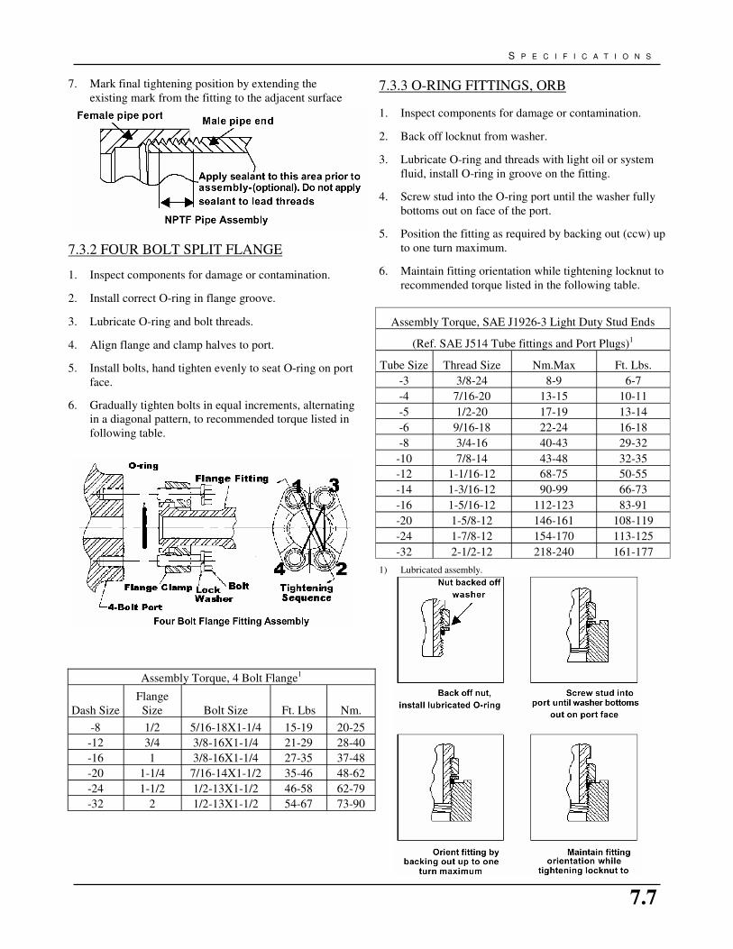
7.7
S P E C I F I C A T I O N S
7. Mark final tightening position by extending the
existing mark from the fitting to the adjacent surface
1) Lubricated assembly.
1. Inspect components for damage or contamination.
2. Back off locknut from washer.
3. Lubricate O-ring and threads with light oil or system
fluid, install O-ring in groove on the fitting.
4. Screw stud into the O-ring port until the washer fully
bottoms out on face of the port.
5. Position the fitting as required by backing out (ccw) up
to one turn maximum.
6. Maintain fitting orientation while tightening locknut to
recommended torque listed in the following table. 1. Inspect components for damage or contamination.
2. Install correct O-ring in flange groove.
3. Lubricate O-ring and bolt threads.
4. Align flange and clamp halves to port.
5. Install bolts, hand tighten evenly to seat O-ring on port
face.
6. Gradually tighten bolts in equal increments, alternating
in a diagonal pattern, to recommended torque listed in
following table.
Assembly Torque, 4 Bolt Flange1
Dash Size
Flange
Size Bolt Size Ft. Lbs Nm.
-8 1/2 5/16-18X1-1/4 15-19 20-25
-12 3/4 3/8-16X1-1/4 21-29 28-40
-16 1 3/8-16X1-1/4 27-35 37-48
-20 1-1/4 7/16-14X1-1/2 35-46 48-62
-24 1-1/2 1/2-13X1-1/2 46-58 62-79
-32 2 1/2-13X1-1/2 54-67 73-90
7.3.2 FOUR BOLT SPLIT FLANGE
7.3.3 O-RING FITTINGS, ORB
Assembly Torque, SAE J1926-3 Light Duty Stud Ends
(Ref. SAE J514 Tube fittings and Port Plugs)1
Tube Size Thread Size Nm.Max Ft. Lbs.
-3 3/8-24 8-9 6-7
-4 7/16-20 13-15 10-11
-5 1/2-20 17-19 13-14
-6 9/16-18 22-24 16-18
-8 3/4-16 40-43 29-32
-10 7/8-14 43-48 32-35
-12 1-1/16-12 68-75 50-55
-14 1-3/16-12 90-99 66-73
-16 1-5/16-12 112-123 83-91
-20 1-5/8-12 146-161 108-119
-24 1-7/8-12 154-170 113-125
-32 2-1/2-12 218-240 161-177

7.8
G R A I N C O N V E Y O R O P E R A T O R ’ S M A N U A L
O-Ring Port Straight Stud Ends
1. Inspect components for damage or contamination.
2. Lubricate O-ring and threads with light oil or system
fluid, install O-ring in groove on the fitting.
3. Screw stud into the O-ring port and tighten to
recommended torque listed in the previous table
Method A. Installation Torque
1. Inspect components for damage or contamination.
2. (Flare-O only) Install correct O-ring in Flare-O groove
(if not installed).
3. Lubricate assembly.
4. Align tube/hose to mating fitting allowing hand
connection. To assure proper alignment, two to three
turns of nut should be easily permitted.
5. Tighten tube nut to torque listed in the following table.
NOTE: Only use flats from finger tight if torque method is
not possible.
Method B. Flats from Finger Tight
1. Inspect components for damage or contamination.
2. Lubricate assembly.
3. Align tube/hose to mating fitting allowing hand
connection. To assure proper alignment, two to three
turns of nut should be easily permitted.
4. Finger tighten or lightly wrench nut to seat sealing
surfaces.
5. Mark nut and adjacent fitting surface to indicate initial
seating position.
6. Finish tightening nut by turning the appropriate
F.F.F.T. as indicated in the following table.
7. Mark final tightening position on fitting by extending
the existing mark from the nut to the adjacent fitting
surface.
Flats From Finger Tight Installation Method1
Tube
Size
Straight
Thread Size
370 Tube
Nut
F.F.F.T.
Flare-O
Tube Nut
F.F.F.T.
Swivel
Nut
F.F.F.T.
Flare-O
Swivel
Nut
F.F.F.T.
-2 5/16-24
-3 3/8-24
-4 7/16-20 2 2 1.5 1.5
-5 1/2-20 2 2 2 2
-6 9/16-18 1.5 1.5 1.5 1.5
-8 3/4-16 1.5 1.5 1.25 1.25
-10 7/8-14 1.5 1.5 1 1
-12 1-1/16-12 1.25 1.25 1 1
-14 1-3/16-12 1.25 1.25 1 1
-16 1-5/16-12 1 1 1 1
-20 1-5/8-12 1 1 1 1
-24 1-7/8-12 1 1 1 1
-32 2-1/2-12 1 1 1 1
1) Recommended for use only when installation by torque method is
not practical.
Assembly Torque, 370 Tube Fittings1
Tube Thread
370 Tube/ Swivel
Nut
Flare-O Tube/
Swivel Nut
-2 5/16-24 6-7 8-9
-3 3/8-24 8-9 11-12
-4 7/16-20 11-12 15-16 7-8 9-11
-5 1/2-20 14-15 19-21 10-12 13-16
-6 9/16-18 18-20 24-28 14-16 19-22
-8 3/4-16 36-39 49-53 21-24 28-33
-10 7/8-14 57-63 77-85 28-32 38-43
-12 1-1/16-12 79-88 107-119 52-56 71-76
-14 1-3/16-12 94-103 127-140 60-64 81-87
-16 1-5/16-12 108-113 147-154 63-72 85-98
-20 1-5/8-12 127-133 172-181 84-96 114-130
-24 1-7/8-12 158-167 215-226 91-104 123-141
-32 2-1/2-12 245-258 332-350 210-240 285-325
Size Size Ft. Lbs. Nm. Ft. Lbs. Nm.
1) Lubricated assembly.
7.3.4 FLARE FITTINGS 370 , JIC

7.9
S P E C I F I C A T I O N S
Beaded Hose Stem Connections 1. Inspect components for damage or contamination.
2. Install hose clamp(s) on hose.
3. Lubricate hose I.D. if permissible.
4. Install hose to fitting.
5. Following hose and clamp manufacturers' instructions,
tighten hose clamp(s).
Note: Beaded hose stem fittings are intended for use in
suction or low pressure lines, typically less than 300 psi.
Follow hose and hose clamp manufacturers instructions for
specific application requirements.
7.3.5 HOSE STEM CONNECTIONS

7.10
G R A I N C O N V E Y O R O P E R A T O R ’ S M A N U A L
MOTOR PART
NUMBER WHERE USED
P0841007
P0841008
P0841009
1314 TRANSFER, SEED SHUTTLE
P0841010
P0841011
P0841012
1515 TRANSFER, 6" SEED CONVEYOR, 8" SEED CONVEYOR, FOUR UNIT SEED SHUTTLE,
WHEEL MOVE DRIVE UNITS, 1330-45 SD CONVEYORS, 1330-45 TD CONVEYORS
P0841019
P0841030
1330-45 FL, 1530-45 SD, 1530-45 FL, 1835 TD, 2000 SERIES SWING-AWAY TRANSFER, PIT-
STOP
7.4 MAXIMUM CONTINUOUS FLOW FOR HYDRAULIC MOTORS
The following table indicates maximum continuous flow that a hydraulic motor can withstand.
These limits should never be exceeded. The lower table lists where each motor is typically used.
If you are unsure which motor you are using, contact your local dealer or distributor for
assistance.
HYDRAULIC MOTOR MAXIMUM CONTINUOUS FLOW
(in3/rev) 2.8 3.2 4.6 4.5 6.3 5.9 8.6
INPUT PRESSURE (psi) 1800 1750 1750 1800 1750 1800 2000
INPUT FLOW (GPM) 12 6 10 15 14 15 15
TORQUE (in·lb) 643 656 980 996 1198 1286 2248
SPEED (rpm) 14 380 472 723 484 559 530
BRAND Char-lynn White White Char-lynn White Char-lynn Parker
PART NUMBER W/Key
Manifold
W/Hole
P0841006
P0841005
P0841007
P0841009
P0841008
P0841011
P0841010
P0841012
P0841040
TYPE H-Series RS RS H-Series RS H-Series TF
(in3/rev) 9.7 10 11.3 12.5 14.1 14.5 17.9
INPUT PRESSURE (psi) 1650 1500 1600 1500 1450 2000 1350
INPUT FLOW (GPM) 15 16 15 16 15 20 15
TORQUE (in·lb) 1950 1585 2205 2127 2493 3782 2905
SPEED (rpm) 342 362 294 291 238 394 185
BRAND Char-lynn White Char-lynn White Char-lynn Parker Char-lynn
PART NUMBER P0841013 P0841001
P0841014 P0841003
TYPE H-Series RS H-Series RS H-Series TF H-Series
(in3/rev) 22.6 4.9 6.2 11.9 14.9 18.7
INPUT PRESSURE (psi) 1250 3000 3000 2250 1750 1500
INPUT FLOW (GPM) 15 20 20 20 20 20
TORQUE (in·lb) 3347 1985 2250 3690 3630 3710
SPEED (rpm) 147 842 662 363 295 236
BRAND Char-lynn Char-lynn Char-lynn Char-lynn Char-lynn Char-lynn
PART NUMBER P0841024 P0841017 P0841019
P0841030
P0841036 P0841020 P0841004
TYPE H-Series 2000S 2000S 2000 2000S 2000S
W/Key
W/Hole

7.11
S P E C I F I C A T I O N S
7.5 CONVEYOR PRODUCT CHART
The following table indicates maximum angle a conveyor
can move grain.
To roughly determine conveyor angle, use angle guide on
right. Set manual on conveyor s-drive or tube and hold
string at A on diagram. String will fall between degree
lines, from this the approximate angle of the conveyor can
be determined.
Grain
Maximum Conveyor
Operating Angle
(degrees)
Alfalfa Pellets 34
Barley 25
Canary Seed 26
Canola 25
Chickpeas 30
Corn 26
Shelled Corn (Dry) 25
Shelled Corn (Wet) 28
Cotton Seed 30-45
Durum 25
Other Materials
Maximum Conveyor
Operating Angle
(degrees)
Sawdust 38
Coal 27-45
Wood Chips >45
Grain
Maximum Conveyor
Operating Angle
(degrees)
Flax 24
Lentils 29
Mustard 26
Oats 28
Peas 30
Rice 36
Rye 25
Soybeans 28
Sunflower 22
Triticale 23
Wheat 26
Use the above chart to determine the angle of the conveyor.
To do this, place this book squarely on the machine. Then using a string
as a plumb bob, with weight attached to one end, hold the string (end
without the weight) on the ‘target’ indicator above. Read angle where
the weighted end of the string falls.
EXAMPLE

7.12
G R A I N C O N V E Y O R O P E R A T O R ’ S M A N U A L


2165 North Service Road West Swift Current, Saskatchewan
CANADA S9H 5K9
PHONE: (306) 773-7779
FAX: (306) 778-2524 EMAIL: [email protected] WEB: www.batcomfg.com
PRINTED IN CANADA P1511015 1.5 REVISED: Jan-07