grain & meat processing - compressed air best practices
TRANSCRIPT

The Magazine for ENERGY EFFICIENCY in Compressed Air, Pneumatics, Blower and Vacuum Systems
Grain & Meat Processing
Mar
ch 2
014
39 PIPI
NG SYST
EM TI
PS
SYST
EMYS
TEM
12 Powdered Egg Company Implements Pneumatic Conveying System
16 Meat Processing Plant Eliminates 1,000 scfm of Compressed Air Flow
24 Compressed Air System Design Recommendations for Food Processors
30 Cornstarch Processor Saves $123,000 in Energy Costs

© Copyright 2014 Atlas Copco Compressors LLC. All rights reserved.
Fast. Forward. Now.
Are you ahead of the curve?Efficiency boosts your bottom line, and no one does efficiency likeAtlas Copco. To keep our products at the leading edge of innovationand in tune with our customers’ needs, the Atlas Copco Group investedmore than $330 million into research and development last year. Thisrelentless focus on innovation gives rise to exciting new energysaving technology.
Whether your energy bill is $1,000 or $100,000 a month, Atlas Copcohas the products that could save you 15% to 50% on these energycosts. Let us prove it to you! Check out the game changing lineup atwww.atlascopco.us/gamechangerusa or call 866-688-9611.
Air compressors, blowers, generators, vacuum, quality air solutions and more.
Atlas - Fast Forward Ad 8.375 x 10.875:Layout 2 1/13/14 5:59 PM Page 1

COLUMNS
5 From the Editor
6 Industry News & Sustainability Reports
45 Resources for Energy Engineers Technology Picks
46 Advertiser Index
49 The Marketplace Jobs and Technology
12 Powdered Egg Company Implements Energy-Saving Pneumatic Conveying System By Doan Pendleton, VAC-U-MAX
16 The System Assessment Meat Processing Plant Eliminates 1,000 scfm of Compressed Air Flow By Don van Ormer, Air Power USA
24 Compressed Air System Design Recommendations for Food Processors By Roderick Smith, Compressed Air Best Practices® Magazine
30 The System Assessment Cornstarch Processor Saves $123,000 in Energy Costs By Hank van Ormer, Air Power USA
39 Piping System Tips for Energy Efficiency By Ron Marshall, for the Compressed Air Challenge®
SUSTAINABLE MANUFACTURING FEATURES
24
12
16
| 0 3 / 1 4
4 airbestpractices.com
COLUMNS

Nutriom manufactures natural powdered egg products in a FSIS USDA facility in Lacey, Washington. The company was looking to replace their screw conveyor system with a pneumatic conveying system to improve efficiency and reduce maintenance requirements in their specialized process. Our lead article, this month, reviews the benefits of Nutriom’s transition to pneumatic conveying systems driven by 60 psig compressed air supporting a vacuum venturi manifold and by another system using vacuum pumps.
In his article, “Meat Processing Plant Eliminates 1,000 scfm of Compressed Air Flow”, veteran auditor Don van Ormer describes several demand-side projects. While demand-reduction opportunities were found on the compressed air dryers, leaks, and condensate drains, the main focus is on 734 scfm of wasted compressed air used at high-pressure blow-off air locations on meat packaging and conveying equipment.
Food processing plants must uphold rigorous food safety and quality standards. How should systems be designed? While there is no single answer for all plants, the compressed air industry, in both the U.K. and Germany, have issued unbiased and detailed recommendations for food plants. Review these in my article, “Compressed Air System Design Recommendations for Food Processors.”
A cornstarch processor spends $553,000 per year on the electricity required to run their centrifugal and rotary screw compressors. Two separate systems delivered 60-75 psig and 80-92 psig compressed air. This required the use of all the air compressors and there were no back-up units. This system assessment story details how the plant was able to reduce demand resulting in annual energy savings of $123,000 and shut down air compressors that now serve as back-up air.
The Compressed Air Challenge®, in an article titled “Piping System Tips for Energy Efficiency,” recommends that the piping differential not exceed 2% of the nominal pressure of the system. This means for a 100 psi system, a pressure differential should not exceed 2 psid from the discharge of the air compressors to the end use (not including the air dryers and filters). To achieve this, pipeline velocities not exceeding 30 fps are normally required on normal piping lengths, with lower velocities for long piping runs, and no more than 50 fps velocities for final piping drops, fittings and hoses.
Thank you for your support and for investing in Compressed Air Best Practices®.
RODERICK SMITH Editor tel: 412-980-9901, [email protected]
FROM THE FROM THE FROM THE EEEDITORDITORDITOR Grain and Meat Processing
COMPRESSED AIR BEST PRACTICES® EDITORIAL ADVISORY BOARD
Indus
trial
Ener
gy M
anag
ers
Doug Barndt Manager, Demand Side Energy-Sustainability Ball Corporation
Eric Battino Productivity Senior Manager PepsiCo
Richard Feustel Senior Energy Advisor SAIC/Wisconsin Focus on Energy
Brad IkenberryEnergy Manager, North America
Michelin
William Jerald Energy Manager CalPortland
Jennifer Meier Global EH&S/ Plant Engineering Manager
Varroc Lighting Systems
Thomas Mort Energy Director Archer Daniels Midlands
Brad Reed Corporate Energy Team Leader Toyota
Brad Runda Global Director, Energy Koch Industries
Don Sturtevant Corporate Energy Manager Simplot
Com
pres
sed
Air S
yste
m A
sses
smen
ts
Jay FrancisDirector, Global Product Management & Strategic Accounts
SPX Flow Industrial
Tilo Fruth President Beko USA
Chris Gordon President Blackhawk Equipment
Paul Humphreys General Manager Edmac Compressor Parts
Paul Johnson Global Sales Manager Parker Hannifin
Kurt Kondas President Universal Air & Gas Products
Mark Krisa Director Global Service Solutions Ingersoll Rand
Frank Langro Director Marketing / Product Management Festo
Ron Marshall Customer Engineering Services
Compressed Air Challenge®
Pierre Noack President Aerzen USA
Wayne Perry Technical Director Kaeser Compressors
Andy Poplin Sales Manager Atlas Machine & Supply
Nitin Shanbhag Senior Manager, Industrial Division Hitachi America
Richard Stasyshan
Technical DirectorCompressed Air & Gas Institute
Hank Van Ormer President Air Power USA
supports:
0 3 / 1 4 |
5 airbestpractices.com
COLUMNS

INDUSTRY INDUSTRY INDUSTRY NNNEWS & EWS & EWS & SSSUSTAUSTAUSTAIIINABNABNABIIILLLIIITY TY TY RRREPORTSEPORTSEPORTS
Chicago Pneumatic announces unique Triple Certification for Stationary Compressors
LRQA grants ISO 9001, ISO 14001:2004 and OHSAS 18001:2007
certification to Chicago Pneumatic’s compressor division
Chicago Pneumatic announced triple certification to ISO 9001, ISO
14001 and OHSAS 18001 standards — three internationally recognized
certification schemes — for Quality, Environmental and Occupational
Health & Safety Management (OHSAS) by Lloyd's Register Quality
Assurance (LRQA) effective December 2013.
This triple certification demonstrates Chicago Pneumatic’s commitment
to the quality of services, care for the environmental impact of its
operations and the health and safety of employees, customers and
the communities that CP serves.
“Chicago Pneumatic focuses
on product substance while
emphasizing customer alignment,”
said Ellen Steck, President,
Chicago Pneumatic. “We take a
systematic approach for continuous
improvement and corrective
action, all while focusing on health
and safety. This commitment to
excellence across all aspects of our
business is what made it possible
to achieve the triple ISO certification, and we’re proud to continue our
stance on reliability, durability and customer value.”
Chicago Pneumatic’s ISO 9001, ISO 14001 and OHSAS 18001
certification recognizes the company’s work across distinct operational
pillars, and is reflective of its dedication to total quality management
across the manufacturing process. Additionally, these certifications
reward Chicago Pneumatic’s commitment to environmental,
occupational health and safety management.
“The triple certification demonstrates the commitment to our
procedures, quality and innovation that has become the backbone of
Chicago Pneumatic’s legacy,” says Steck. “We are honored to receive the
triple certification, and our customers can rest assured that our almost
100-year commitment to product excellence and customer service will
continue for the next 100 years and beyond.”
Chicago Pneumatic is among the industry leaders in compressed air
solutions, which are engineered for high-performance. As part of
the global Atlas Copco Group, Chicago Pneumatic offers a full range
of reciprocating and rotary screw compressors and dryers to help
customers tackle everything from everyday tasks to the most complex
industrial process.
For more information about Chicago Pneumatic industrial air compressors, or to find a distributor near you, please visit www.cp.com
“We take a systematic approach for continuous improvement and corrective action, all while focusing on health and safety.
This commitment to excellence across all aspects of our business is what made it possible to achieve the triple ISO certification.”
— Ellen Steck, President, Chicago Pneumatic
| 0 3 / 1 4
6 airbestpractices.com
COLUMNS


INDUSTRY NEWS & SUSTAINABILITY REPORTS
Festo Names Three New Distributors
Festo has named three new western states distributors. These include
Denver-based Consolidated Parts, Inc. for Colorado product distribution,
Salt Lake City-based Pro Automation, Inc. for Utah, and Custom Fluid
Power, located in Nampa, Idaho, for distribution of Festo products
in parts of Idaho, Oregon, and the state of Montana.
“The best distributors in automation today have advanced parts stocking
and distribution systems in place as well as the engineering expertise
to help customers quickly identify optimum solutions,” said Bill Oliver,
Head of Festo US Distribution. “These distributors invest in training
their personnel and instilling a culture of service. We know that
Festo products are in exemplary hands with Consolidated Parts,
Pro Automation, and Custom Fluid Power.”
| 0 3 / 1 4
8 airbestpractices.com
COLUMNS

HIGH EFFICIENCY, HIGH PERFORMANCEINDUSTRIAL AIR COMPRESSORS
Featuring variable speed drivetechnology and an extremely lowmaximum 55 amp draw enablinginstallations in locations previouslyuneconomical or impossible.
REVOLUTIONARY 10 HP SINGLE PHASEROTARY SCREW AIR COMPRESSOR
HURON B10 AIRSYSTEM®
• Cast Iron Pumps with Low RPM• Proprietary Pressure Lubrication• High-Efficiency Intercooler• 7 Year Limited Warranty
HEAVY DUTY INDUSTRIALRECIPROCATING AIR COMPRESSORSBuilt to withstand the most demanding industrial environments.
DV SYSTEMS BUILT BETTERDeSigneD, engineeReD & manuFactuReD in noRth ameRica
100 pluS yeaRS
Hello from Charlotte, North Carolina!DISTRIBUTOR OPPORTUNITIES AVAILABLE, CONTACT US TO LEARN MORE
call 877.687.1982 [email protected]
RotaRy ScRew aiR compReSSoRS RecipRocating aiR compReSSoRS • aiR DRyeRS oil FRee • FilteRS • aiR management SyStemS
aiR toolS • aiR pipe • maintenance • acceSSoRieS
DVad16_Layout 1 13-10-17 5:06 PM Page 1
Consolidated Products has served Colorado
machinery manufacturers and automation
end users with parts and engineering services
for more than 65 years in such fields as
packaging, robotics/palletizing, oil and gas,
mining, solar, and material handling. The
company also serves automation system
integrators. Consolidated Products is an
Automation Solutions Provider member of the
Association for High Technology Distribution.
Pro Automation is a full-line stocking
distributor of industrial automation
components. With more than 14 years of
experience in the Utah market, Pro Automation
assists customers with sales and value
added products and services. The company
specializes in motion control and assembly
solutions. Pro Automation serves such markets
as material handling, automotive, printing/
converting, furniture, aerospace, construction,
life science, energy, recreation, transportation,
and agriculture.
Consolidated Fluid Power is a full-line
stocking distributor of fluid power components
and accessories with more than 20 years
experience. The company will distribute
Festo products in Idaho, expect for the
counties of Bonner and Boundary, the state
of Montana, and in the Oregon counties of
Baker, Grant, Harney, Malheur, Union, and
Wallowa. Consolidated Fluid Power assists
customers with sales, design, and value added
products and services in such markets as
food processing, dairy and farm equipment,
packaging, semi-conductor, timber, mining,
and land transportation.
For more information on Festo, call 800-993-3786 and visit www.festo.com/us
0 3 / 1 4 |
9 airbestpractices.com
COLUMNS

INDUSTRY NEWS & SUSTAINABILITY REPORTS
Atlas Copco Compressors Benefit a South Wales Coal Mine
Compressors from Atlas Copco are providing an essential supply of compressed air to coal
extraction operations for Unity Mine in the Neath Valley. The decision to replace the existing
diesel driven compressors with Atlas Copco GA electrically-powered screw compressors
has resulted in significant benefits in terms of process efficiency, energy use and reduced
environmental impact. The mine, which re-opened in 2008, is now in the process of moving
to full production with the capability to produce up to one million tonnes of coal per year.
It is contracted to supply fuel for major industrial companies, such as the nearby coal-fired
Aberthaw Power Station.
Unity Mine’s Cwmgrwach operation is a drift mine, meaning that miners can walk in rather
than being transported, via a vertical mine shaft winding system, as used in other deep mining
sites. At the mine, the coal seams are accessed by driving sloping tunnels through the ground.
It was the first to be opened in Wales since the Betws colliery in Ammanford in 1974 and
is poised to take advantage of a market whereby the increasing volume of imported coal,
coupled with global price increases and demand, driven mainly by booming economies such
as China and India, makes formerly uneconomic domestic sites commercially viable again.
After the mine’s re-opening, the company’s management focus was on the reliability and
efficiency of production equipment. Duncan Kilbride, Director of Projects & Procurement
at Unity Mine explains: “The initial plan of the mine’s workings were based on the pillar
| 0 3 / 1 4
10 airbestpractices.com
COLUMNS

and stall extraction methods that employ a continuous miner
unit and secure the work with roof bolting, as opposed to arched
roadways. These all require air-driven equipment fed by a reliable
continuous supply of compressed air. We also operate pumps on
a permanent basis to remove water.”
Air for these operations was supplied originally from a number of small,
rented diesel-driven compressors but there was growing concern with
their mechanical reliability and the risks of any break in the regular
supply of diesel fuel. This dependency issue, coupled with increasing
rental and fuel costs, made it evident that replacement with more energy
and cost-efficient compressors was essential.
“We invited tenders for the system and Atlas Copco came up trumps
as a one-stop shop solution for the compressors, filtration units,
controller and compressor house installation. They scored as a
world-leading specialist offering long term options on a range of
packages best suited to our needs within the required timescale
plus an ongoing support organisation”, said Duncan Kilbride.
Two oil-lubricated, air-cooled, full-feature GA110 variable speed drive
screw compressors were installed together with a companion fixed-
speed version machine. It has been calculated that energy savings in
the region of £13,000 per year are achievable, in addition to substantial
savings in equipment rental costs. These Atlas Copco compressor units
provide base load and back up peak 7 bar air to the drilling and roof
bolting equipment, and the water pumps. Current geological estimates
are that there are reserves of 90 million tons of coal that will be
extracted from the Cwmgwrach mine complex over the next 25 years.
Visit www.atlascopco.com
To read more To read more To read more Industry NewsIndustry NewsIndustry News articles, articles, articles,Industry News articles,Industry NewsIndustry NewsIndustry News articles,Industry News articles,Industry News articles,Industry NewsIndustry NewsIndustry News articles,Industry Newsvisit www.airbestpractices.comvisit www.airbestpractices.comvisit www.airbestpractices.com
0 3 / 1 4 |
11 airbestpractices.com
COLUMNS

Nutriom sets the bar high when it comes to producing its premium
quality natural powdered egg products Ova Easy® and Egg Crystals®, that
are sold at outdoor retailers such as REI, and online merchants such as
Amazon.com; so, when the screw conveyor in their FSIS USDA facility
required regular unexpected attention, Leonardo Etcheto, Plant Manager
at the Lacey, WA facility knew it was time to look for a better solution.
Seeking a Unique Conveying System
Nutriom developed a unique process to produce its egg products
which preserves the flavor and functionality of the eggs, and needed
a materials handling system that would work within that specialized
process to improve efficiency without damaging the crystals.
“The screw conveyor was a difficult system to handle,” says Etcheto.
“There were a lot of moving parts and that meant there were more
things that could go wrong. It was a difficult system to clean and
to perform maintenance.”
Improved efficiency and gentle transfer weren’t the only provisions
Etcheto required. “Our technology is very different and we’re a little
pickier than your average company. We needed a conveyor manufacturer
that was able to modify its equipment to meet our needs,” he says.
When attending a trade show for food manufacturers, Etcheto visited the
booths of conveyor manufacturers. “We wanted something that would
not touch the product, allow us to be full stainless steel, and one of the
biggest things is we wanted to get away from having to use oil,” he says.
The food-grade screw conveyor at the Lacey plant had a plastic housing
outside the screw conveyor. Plastic components from equipment in
the food industry hold the potential to deposit debris or shavings into
product undetected, and Nutriom preferred to eliminate that potential.
The screw conveyor also housed a gearbox on top of the unit that
required expensive H1 lubricants that on occasion, despite regular
maintenance, would leak and create a mess.
Powdered Egg Company Implements Energy-
Saving Pneumatic Conveying System
“Our technology is very different and we’re a little pickier than your average company. We needed a conveyor manufacturer
that was able to modify its equipment to meet our needs.”— Leonardo Etcheto, Plant Manager, Nutriom
By Doan Pendleton, VAC-U-MAX
| 0 3 / 1 4
12 airbestpractices.com
SUSTAINABLE MANUFACTURING FEATURESSUSTAINABLE MANUFACTURING FEATURES

COMPRESSED AIR ALSO PRODUCES OILY CONDENSATE*
Help ensure it doesn’t impact ourENVIRONMENT.
JORC Zero Air-Loss Condensate Drains and Oil/Water Separators provide
SUSTAINABLE CONDENSATE MANAGEMENT
Zero Air-Loss Condensate Drains
Lock-Down Air Leaks
JORC Industrial LLC. • 1146 River Road • New Castle, DE 19720Phone: 302-395-0310 • Fax: 302-395-0312 • [email protected] • www.jorc.com
*A 250 hp compressor can produce 40,515 gallons of oily condensate per year.
Sepremium Oil/Water Separator
Air-Saver G2
Smart Guard Ultra
Electronic
No Electricity Required
Mag-11 - 230 psi POD-DC Non-Electric
Smart Guard
Pneumatic Conveying Protects High Quality Products
After contacting a couple of East coast pneumatic conveyor
manufacturers, Etcheto decided that one of the manufacturers could
accommodate all his requirements. “We have a lot of height restrictions
because our building is older and has many areas with low ceilings and
VAC-U-MAX was able to come up with a system that could fit in the space
that we needed to fit into.”
Celebrating its 60th year designing and manufacturing innovative
pneumatic conveyor systems and support equipment for the conveying,
weighing, and batching of dry materials, Belleville, NJ-based VAC-U-MAX
is a pioneer with many industry firsts including air-powered venturi
power units, direct-loading of vacuum-tolerant process equipment,
and vertical-wall Tube Hopper material receivers.
Etcheto began with one pneumatic conveying system from the company
and, based on its successful performance, “we just kept adding,” he says.
The facility utilizes two pneumatic conveyors that connect to packaging
systems, two that connect to the low temperature driers and two that
connect to a mixer — one system breaks up the powder and puts it into
the mixer and the other pulls it out.
“One of the reasons we use pneumatics is because we produce a very
high quality, high priced product and we want to make sure that we
maintain the high quality. The systems do a good job pulling the product
without damaging it.”
Previously, the screw conveyor would grind the egg product down as it
transferred the material which made the crystals more difficult to handle.
The screw conveyor also needed a fair amount of egg to be in the system
for it to work properly which would sometimes bog down the process.
“The enclosed system allows for more ideal handling,” says Etcheto. “It’s
standard GMP to make sure that nobody is handling our product, and
the system easily allows us to do that. It is always traveling pneumatically
through stainless lines,” he says. “It is definitely cleaner than the screw
conveyor we used before.”
0 3 / 1 4 |
13 airbestpractices.com
SUSTAINABLE MANUFACTURING FEATURESSUSTAINABLE MANUFACTURING FEATURES

Experience with Food Manufacturers
VAC-U-MAX vacuum conveying systems are
fully enclosed, protecting materials from air,
dirt and waste. Because product does not
escape from a vacuum conveying system,
particulates that can endanger or jam
expensive equipment are prevented from
entering the environment.
Having worked with a host of major food
manufacturers including General Mills, Kraft
Foods, and Kellogg Company, as well as
many smaller specialty food manufacturers,
the conveyor manufacturer is no stranger
to the strict regulations that exist in the
food industry. This expertise lent itself to
understanding the needs of Nutriom and
the creation of a custom system that was
more efficient, reduced labor, improved
ergonomics, and made compliance with
stringent FSIS USDA regulations simpler.
The vacuum conveying systems are complete
stainless steel construction and all product
contact areas are 316L with a polished
surface for ease of cleaning and product flow.
Nutriom utilizes two separate types of vacuum
generation to accommodate its unique
process. For areas with low ceiling clearance
VAC-U-MAX modified its filter lids to fit the
tight spaces and these units use compressed
air to generate vacuum. In areas where
ceiling height is not an issue, more efficient
vacuum pumps are utilized.
To further accommodate Nutriom’s stringent
standards, the conveyor manufacturer replaced
the iron rings that secured the filter with
stainless steel rings. Etcheto says, “they’re
cleaner, fit better within our inspection system
and last a lot longer.”
In addition to streamlining materials transfer
and enhancing sanitation practices, the system
Nutriom uses two VAC-U-MAX pneumatic conveyors with a mixer — one system breaks the powder up and puts it into the mixer and the other pulls it out of the mixer.
POWDERED EGG COMPANY IMPLEMENTS ENERGY-SAVING PNEUMATIC CONVEYING SYSTEM
| 0 3 / 1 4
14 airbestpractices.com
SUSTAINABLE MANUFACTURING FEATURES

COMPRESSED AIR IS ENERGYDon’t let it go to waste
Our low-cost, easily-installed flowmeters are changing
the way people manage their compressed air systems.
Metering branch lines reveals dramatic savings opportuni-
ties and ensures that once savings are achieved, they are
maintained.
www.cdimeters.com
Phone: 781-935-9600 • Toll free (US and Canada): 866-885-2462To read more To read more To read more Vacuum Technology Vacuum Technology Vacuum Technology articles, articles, articles, visit www.airbestpractices.com/technology/visit www.airbestpractices.com/technology/visit www.airbestpractices.com/technology/
vacuumvacuumvacuum
VAC-U-MAX custom pneumatic conveying system above filling machine at Nutriom plant.
has also improved ergonomics in the plant.
“One of our systems only moves the powder
about 10 feet, but it moves 10 feet up. Before
implementing the pneumatic conveyors, the
material had to be transferred manually and
now that’s not an issue,” says Etcheto.
In the beginning, there was a learning curve,
he says. “You’ve got to set them up right.
You can’t have tight turns, you need the right
amount of air flow, but once you figure them
out, they really aren’t that complicated.”
Etcheto appreciates that the VAC-U-MAX
system uses standard dairy wiring with
all 30A clamps, and says that operators do
most of the maintenance themselves and have
no issues keeping the systems running. The
systems he says are “easy to put together and
take apart because they use standard parts
the operators are used to, and they don’t
need tools.”
“Over time, it’s really been surprising how
reliable the VAC-U-MAX systems are,” says
Etcheto. “With the screw conveyor we had to
do something to it at least once a month. By
replacing it with a pneumatic conveying system,
we have saved over $150,000 annually. That
is really good technology.”
For more information contact Doan Pendleton, Vice President Sales, VAC-U-MAX.
Founded in 1954, VAC-U-MAX has been at the forefront of leading edge conveying systems and components across a wide range of industries including food, pharmaceutical, chemical and industrial markets. To learn more about how VAC-U-MAX pneumatic conveying systems can improve efficiency, ergonomics, preserve product integrity, or reduce costs, write to them at 69 William Street, Belleville, NJ 07109; call 1-800-822-8629; e-mail [email protected]; or visit www.vac-u-max.com.
POWDERED EGG COMPANY IMPLEMENTS ENERGY-SAVING PNEUMATIC CONVEYING SYSTEM
0 3 / 1 4 |
15 airbestpractices.com
SUSTAINABLE MANUFACTURING FEATURES

THE SYTHE SYTHE SYSTSTSTEM AEM AEM ASSSSSSEEESSSSSSMENMENMENTTTMeat Processing Plant Eliminates 1,000 scfm of Compressed Air FlowBy Don van Ormer, Air Power USA
This food & beverage plant is a large (500,000 sq ft) meat processing
plant with twenty packaging lines and nine palletizers. The compressed
air system is supplied from three separate rooms with seven individual
lubricant-cooled, single and two-stage rotary screw compressors.
The plant has four blower purge desiccant dryers designed to deliver
a -40 ˚F pressure dewpoint.
Current System Summary
Annual plant electric costs for compressed air production, as operating
today, are $230,640 per year. If the electric costs of $32,640 associated
with operating ancillary equipment, such as dryers are included, the
total electric costs for operating the air system are $263,100 per year.
These estimates are based upon a blended electric rate of $0.06 /kWh.
The air system operates 8,760 hours per year. The load profile or air
demand of this system is relatively stable during all shifts. Overall system
flow ranges from 2,554 acfm during production to 1,903 acfm during
sanitation. The system pressure runs from 96 to 100 psig in the headers
during production.
Production is 16 hours per day, 6 days a week; sanitation is 8 hours
per day, 6 days a week; and non-production is on Sunday. Energy cost
estimates are based upon a blended rate of $0.06 per kWh.
Primary Air Compressor Supply
Compressor Capacity Control
The two most effective ways to run air compressors are at “Full Load”
and “Off.”
Capacity controls are methods of restricting the output air flow delivered
to the system while the unit is running. This is always a compromise
and is never as efficient as full load on a specific power (cfm/hp) basis.
| 0 3 / 1 4
16 airbestpractices.com
SUSTAINABLE MANUFACTURING FEATURESSUSTAINABLE MANUFACTURING FEATURES

Rotary Screw Controls (Oil-free / Lubricant-cooled)
The two most common control methods used for rotary screw
compressors are modulation and on-line/off-line. Modulation
is relatively efficient at higher loads, but less efficient at lower loads.
On-line/off-line controls are very efficient for loads below 60% when
properly applied with adequate time for blow down. There are several
other control types — e.g., “variable displacement” (75% to 100%
load) and “variable speed drive” (25% to 75% load) — that have very
efficient turn down from when applied correctly. Two-stage, oil-free,
rotary screws generally are not applied with modulation. As a result they
use either two-step (full-load/no-load) or VSD capacity controls.
These controls must be installed correctly to operate efficiently. Piping
and storage should be available close to the unit with no measurable
pressure loss at full load to allow the signal to closely match the air
requirements.
“Reducing average compressed air consumption was the key to improving the efficiency of this food processing plant. Spending time examining compressed air leaks and the packaging equipment allowed our team
to find the major compressed air flow-reduction opportunities.”— Don van Ormer, Air Power USA
0 3 / 1 4 |
17 airbestpractices.com
SUSTAINABLE MANUFACTURING FEATURESSUSTAINABLE MANUFACTURING FEATURES
THE SYSTEM ASSESSMENT | Meat Processing Plant Eliminates 1,000 scfm of Compressed Air Flow
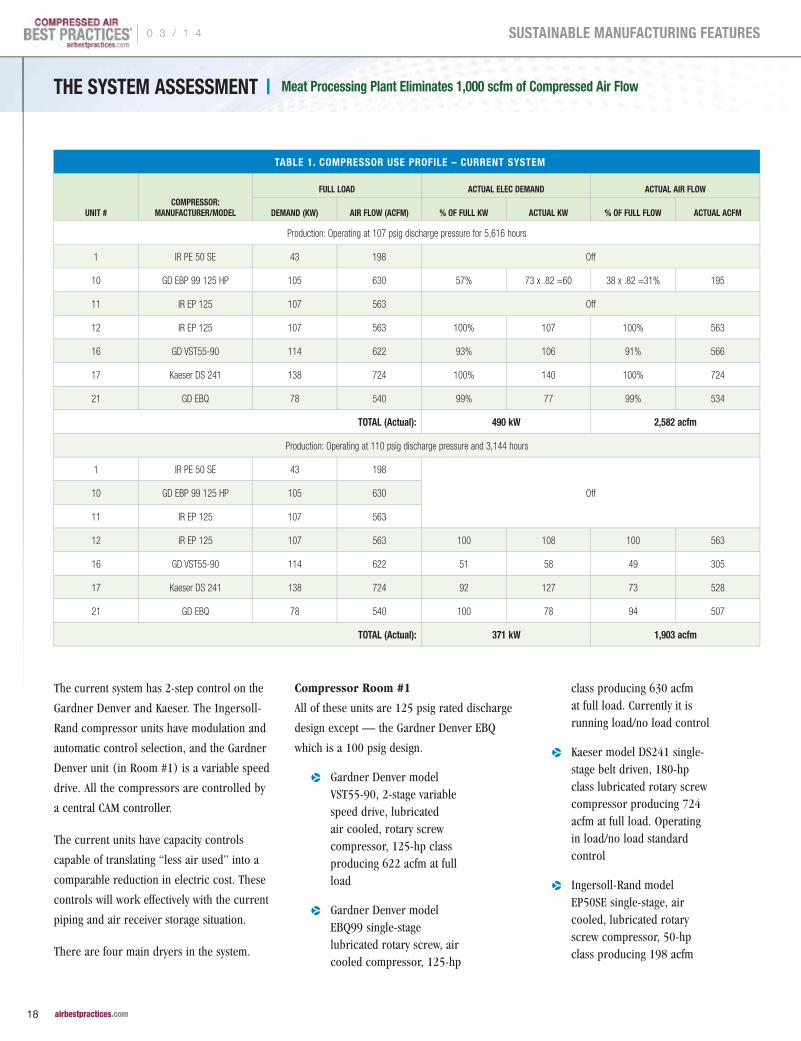
The current system has 2-step control on the
Gardner Denver and Kaeser. The Ingersoll-
Rand compressor units have modulation and
automatic control selection, and the Gardner
Denver unit (in Room #1) is a variable speed
drive. All the compressors are controlled by
a central CAM controller.
The current units have capacity controls
capable of translating “less air used” into a
comparable reduction in electric cost. These
controls will work effectively with the current
piping and air receiver storage situation.
There are four main dryers in the system.
Compressor Room #1
All of these units are 125 psig rated discharge
design except — the Gardner Denver EBQ
which is a 100 psig design.
p Gardner Denver model VST55-90, 2-stage variable speed drive, lubricated air cooled, rotary screw compressor, 125-hp class producing 622 acfm at full load
p Gardner Denver model EBQ99 single-stage lubricated rotary screw, air cooled compressor, 125-hp
class producing 630 acfm at full load. Currently it is running load/no load control
p Kaeser model DS241 single-stage belt driven, 180-hp class lubricated rotary screw compressor producing 724 acfm at full load. Operating in load/no load standard control
p Ingersoll-Rand model EP50SE single-stage, air cooled, lubricated rotary screw compressor, 50-hp class producing 198 acfm
TABLE 1. COMPRESSOR USE PROFILE – CURRENT SYSTEM
UNIT #COMPRESSOR:
MANUFACTURER/MODEL
FULL LOAD ACTUAL ELEC DEMAND ACTUAL AIR FLOW
DEMAND (KW) AIR FLOW (ACFM) % OF FULL KW ACTUAL KW % OF FULL FLOW ACTUAL ACFM
Production: Operating at 107 psig discharge pressure for 5,616 hours
1 IR PE 50 SE 43 198 Off
10 GD EBP 99 125 HP 105 630 57% 73 x .82 =60 38 x .82 =31% 195
11 IR EP 125 107 563 Off
12 IR EP 125 107 563 100% 107 100% 563
16 GD VST55-90 114 622 93% 106 91% 566
17 Kaeser DS 241 138 724 100% 140 100% 724
21 GD EBQ 78 540 99% 77 99% 534
TOTAL (Actual): 490 kW 2,582 acfm
Production: Operating at 110 psig discharge pressure and 3,144 hours
1 IR PE 50 SE 43 198
Off10 GD EBP 99 125 HP 105 630
11 IR EP 125 107 563
12 IR EP 125 107 563 100 108 100 563
16 GD VST55-90 114 622 51 58 49 305
17 Kaeser DS 241 138 724 92 127 73 528
21 GD EBQ 78 540 100 78 94 507
TOTAL (Actual): 371 kW 1,903 acfm
| 0 3 / 1 4
18 airbestpractices.com
SUSTAINABLE MANUFACTURING FEATURES

p Great Lakes model GEHD-750 external heat, blower purge dryer rated for 750 scfm. It has a 5-hp blower and a 24 kW heater. Currently, it is operating using purge air for regeneration with blower cooling. It is using 15% of its rated flow for three hours and the blower for one hour
p Ingersoll-Rand model TZB1600 external heat blower purge dryer rated for 1,600 scfm. It has a 7.5-hp blower and a 30 kW heater. Purge control is installed but it is running on timer mode. This dryer is using purge air for cooling which is 15% for one hour of cooling
THE SYSTEM ASSESSMENT | Meat Processing Plant Eliminates 1,000 scfm of Compressed Air Flow
Figure 1. Current Compressed Air System — Compressor Room #1
0 3 / 1 4 |
19 airbestpractices.com
SUSTAINABLE MANUFACTURING FEATURES

THE SYSTEM ASSESSMENT | Meat Processing Plant Eliminates 1,000 scfm of Compressed Air Flow
TABLE 2: HIGH-PRESSURE BLOW-OFF AIR LOCATIONS
LOCATION QTY TYPE / SIZE ESTIMATED CURRENT
CFM USAGE UTILIZATION
% NET AVG
CFM
RECOMMEND VENTURI NOZZLE
NEW AVG NET CFM EACH
NET AVG CFM
USAGE
TIMED W / PROCESS – REDUCTION
PERCENTAGE
EST NET AVG CFM
SAVED
Breast Pack Bag Open 2 1" Venturi 8 x 2 90 14.4 -- 14.4 -- 20 3
Breast Pack Cryovac 8600-4
16 Blue Lechler 16 x 16 90 230 8 – 48008 7x8=56 50 60 210
Breast Pack Video Jet 2 Blue Lechler 16 x 2 50 16 1 – 48008 1 x 7 3.5 Current 12.5
Breast Bake Cryovac 8600-7
16 ¼" Tube 20 x 16 (two at a time for 2 seconds)
0.66 x .9 24 8 – 48008 1 x 7 4 Current 20
Breast Pack Approach Convey #2
2 1" Venturi 16 90 14.4 -- -- -- 20 3
Bologna 1 1" Venturi 8 90 7.2 -- 7.2 -- 20 3
Pack Bag Open BM Convey
2 1" Venturi 8 x 2 90 14.4 -- 14.4 -- 20 3
Cryovac 8600-8 16 ¼" Tube 20 x 16 (two at a time for 2 seconds)
0.66 x .9 24 8 – 48008 1 x 7 4 Current 20
Cryovac 8600-9 2 Blue Lechler 16 x 2 0.66 x .9 19 2 – 48008 2 x 7 8 Current 11
Cryovac 8600-9 14 ¼" Tube 20 x 14 (two at a time for 2 seconds)
0.66 x .9 24 8 – 48008 1 x 7 4 Current 20
P3 Beef Raw Roto screen for Beef Pumper
3 Blue Lechler 16 x 3 90 43 3 – 48008 3 x 7 = 21 19 20 23
Cryovac 8600-6 8 Blue Lechler 16 x 8 (one at a
time for 2 seconds) 0.66 x .9 9.5 8 – 48008 1 X 7 4 Current 5.5
Cryovac 8600-6 8 ¼" Tube 20 x 8 (one at a
time for 2 seconds) 0.66 x .9 12 Remove -- -- -- 12
P3 Sausage Caramel Blow
1 3' x 1" Pipe 20 Holes 60 90 56 Remove -- -- -- 56
P3 Sausage Caramel Blow
1 3' x 1" Pipe 20 Holes 60 90 56 4 – 48008 4 x 7 28 -- 28
P3 Sausage Oven Exit 1 3' x 1" Pipe 20 Holes 60 90 56 Remove -- -- -- 56
P3 Sausage Oven Exit 1 3' x 1" Pipe 20 Holes 60 90 56 4 – 48008 4 x 7 28 -- 28
Frank Plant Retail Stuffing Exit to Bulk Pkg
1 Blue Lechler 16 100 16 Remove -- -- -- 16
Frank Plant Retail Stuffing Exit to Bulk Pkg
1 1/2" Pipe 10 Holes 20 100 20 Remove -- -- -- 20
Wex Xar Case Packers 2,3,4,&5
4 ¼" Blow Gun Nozzle 20 x 4 10 8 Remove -- -- -- 8
Pump & Tumble
Injector 3 4 Blue Lechler 16 x 4 90 58 2 – 48008 2x 7 13 Current 45
Cryovac 8600-3 8 Blue Lechler 16 x 8 (one at a
time for 2 seconds) 0.66 x .9 9.5 8 – 48008 1 X 7 4 Current 5.5
Cryovac 8600-3 8 3/8" Pipe with 6 –
1/8" holes 16 x 8 (one at a
time for 2 seconds) 0.66 x .9 24 Remove -- -- -- 24
Pump & Tumble Injector 1
4 Blue Lechler 16 x 4 90 64 2 – 48008 2 x 7 13 -- 51
Pump & Tumble Injector 1
4 Blue Lechler 16 x 4 90 64 2 – 48008 2 x 7 13 -- 51
Total Current Usage 939.4 Proposed Usage 734.5
| 0 3 / 1 4
20 airbestpractices.com
SUSTAINABLE MANUFACTURING FEATURES

THE SYSTEM ASSESSMENT | Meat Processing Plant Eliminates 1,000 scfm of Compressed Air Flow
p The pre-filters to the Ingersoll-Rand TZB dryer are an NLM1500 and a HE2100 coalescing, and the after-filter is a HE2100 particulate
Compressor Room #2
p Two Ingersoll-Rand model EP125 single-stage, air cooled, 125-hp class rotary screw compressors producing 563 acfm at full load pressure of 125 psig
p Sahara model BP1690 external heat blower purge dryer rated for 1,690 scfm. A dewpoint demand controller is installed and utilized. This dryer is also equipped with a 5-hp blower and a 30 kW heater
p The prefiltration is an Ingersoll-Rand NLM1500 and then a Hankison coalescing pre-filter model HSF3 with a Hankison particulate HSF3 after-filter
Compressor Room #3
p Gardner Denver model EBP, 100-hp class single-stage air cooled, rotary screw compressor producing 440 acfm at full load
p AirCel model AEHD500 external heat blower purge dryer rated for 500 scfm. Equipped with a dewpoint demand controller and a 9 kW heater and 7.5-hp blower
p The dryer has an Ingersoll-Rand 500 scfm rated pre-filter and is equipped with a 500-cfm rated after-filter
The Proposed Compressed Air Flow-Reduction Projects
The estimated savings potential of the projects
related to operating the air compressors
totals $107,522 per year. Adding in the
savings potential of $12,780 from other
projects related to operating the compressed
air dryers provides a total savings estimate
for the entire set of projects of $120,302.
Together, these projects can be completed
at a cost of $21,900, resulting in a simple
payback of two months.
Compressed Air Flow-Reduction Projects
Utilize blower cooling on
Ingersoll-Rand TZB dryer
60 acfm
Utilize blower cooling and
regeneration on Great Lakes
dryer
85 acfm
Replace four timer drains
with level-activated type
12 acfm
Repair identified leaks,
continue leak management
program
150 acfm
Install thermostatic control
on Vortec cooler in
KLIKKLOK
28 acfm
Install venturi nozzles on
identified blow-off air
locations
734 acfm
Replace two air motors in
Tipper Tie 1 and 2
18 acfm
Total Reduction 1,087 acfm
CRP Oil/Water Separators that Work100% of the time on 100% of compressor lubricants
Clean Resources • www.cleanresources.com • 800-566-0402
No Maintenance
Guaranteed to reduce effluent to less than 10 ppm
EPA Compliant
100% of the time on 100% of compressor lubricants
www.cleanresources.com
Separators that Work100% of the time on 100% of compressor lubricants
• 800-566-0402 www.cleanresources.com
100% of the time on 100% of compressor lubricants
www.cleanresources.com
0 3 / 1 4 |
21 airbestpractices.com
SUSTAINABLE MANUFACTURING FEATURES

Other Projects (Total Reduction = $12,780)
Utilize dew point demand on
IR TZB dryer
$7,384 / yr
Install dew point demand on
Great Lakes dryer
$2,440 / yr
Install dew point demand on
AirCel dryer
$2,956 / yr
Open Blows
Due to article space limitations, we will only outline the compressed air
flow-reduction project focusing on installing venturi nozzles on blow-off
air locations.
With open blows, turbulent compressed air blasts straight out of the
pipe or tube. It not only wastes huge amounts of compressed air, but
also violates OSHA noise and dead ended pressure requirements.
Air jets and air flow-inducing nozzles used in place of open blows can
reduce noise level, lower compressed air use, and most often improve
blow-off operation in both productivity and quality.
Air Power USA, Inc. has developed the following data over time. It is
relative to specific standard products available in the industry. A test
of one nozzle may vary somewhat from another nozzle of the same
manufacturer, but not significantly. Below are some important points
to remember:
p In blow-off, thrust from pressure (psig), is required to loosen the objects to be removed
p Thrust dissipates very rapidly once the air has left the “blow-off” device
p In blow off, volume of total air (cfm), compressed air plus induced air, is critical to carrying the blown-off material away within the air stream
THE SYSTEM ASSESSMENT | Meat Processing Plant Eliminates 1,000 scfm of Compressed Air Flow
TABLE 3. SUMMARY OF KEY COMPRESSED AIR SYSTEM PARAMETERS AND PROJECTED SAVINGS
CURRENT SYSTEM PROPOSED SYSTEM
SYSTEM COMPARISON PRODUCTION SANITATION / WEEKENDS PRODUCTION SANITATION / WEEKENDS
Average Flow (cfm) 2,582 1,903 1,495 816
Compressor Discharge Pressure (psig) 107 110 107 110
Average System Pressure (psig) 99 100 99 100
Electric Cost per cfm $56.84 /cfm/yr $44.07 /cfm/yr $57.09 /cfm/yr $46.27 /cfm/yr
Electric Cost per psig $733.82 /psig/yr $419.37 /psig/yr $426.81 /psig/yr $188.77 /psig/yr
Electric Demand 490 kW 371 kW 285 kW 167 kW
Annual Electric Cost $146,765 $83,875 $85,363 $37,755
$230,640 /yr $123,118 /yr
“The compressed air equipment was in good working order. The controls on the air compressors and the compressed air
dryers simply needed to be used to their full potential.”— Don van Ormer, Air Power USA
| 0 3 / 1 4
22 airbestpractices.com
SUSTAINABLE MANUFACTURING FEATURES
THE SYSTEM ASSESSMENT | Meat Processing Plant Eliminates 1,000 scfm of Compressed Air Flow
To learn more, visit www.aerzenusa.com108 Independence Way • Coatesville, PA 19320
(610) 380-0244 • [email protected]
Learn how to save energy andincrease operating efficiencieswith the Aerzen Delta Hybrid
Rotary Lobe Compressor.
A New Twist in Energy-Efficient Air
• Substantial energy savings
• Reliable and durable
• Space saving, easy handling
• Reduction of maintenance costs
• Simple operation up to +22psig / -21”Hg
Aerzen Compressed Air Ad RND2_Aerzen Compressed Air Ad 8/15/11 3:47 P
To read more To read more To read more Food Industry System Assessment Food Industry System Assessment Food Industry System Assessment articles, articles, articles, Food Industry System Assessment articles, Food Industry System Assessment Food Industry System Assessment Food Industry System Assessment articles, Food Industry System Assessment articles, Food Industry System Assessment articles, Food Industry System Assessment Food Industry System Assessment Food Industry System Assessment articles, Food Industry System Assessmentvisit www.airbestpractices.com/system-assessmentsvisit www.airbestpractices.com/system-assessmentsvisit www.airbestpractices.com/system-assessments
p Use expensive compressed air only as a last resort; mechanical, hydraulic, etc., will always be more energy economical and often safer
p All blow-off air should be regulated to the lowest effective pressure — higher pressure means higher flow, which may not be heeded; higher pressure air costs more to produce. Blower pressure air is cheaper
p Use Venturi air amplifier nozzles whenever and wherever possible — properly selected and applied for needed thrust and volume, this will usually reduce blow-off air at least 50%, freeing up more air flow for other more valuable applications
p All blow-off air should be shut off (automatically) when not needed for production
p When blower-generated air is available or apparently economically feasible, always compare the net energy cost to alternatives
p There is substantial potential savings to install automatic compressed air shut-off at various points using blow-off air. This will shut off the compressed air whenever the line stops or the product flow is interrupted. It will automatically blow again when needed, as sensed. If the plant does not have a current PLC or electric eye system in place, we recommend choosing something similar to the Exair Model Electric Eye Controller, which is economical and simple to install
Summary
Reducing average compressed air consumption was the key to
improving the efficiency of this food processing plant. Spending
time examining compressed air leaks and the packaging equipment
allowed our team to find the major compressed air flow-reduction
opportunities. The compressed air equipment was in good working
order. The controls on the air compressors and the compressed air
dryers simply needed to be used to their full potential.
For more information contact Don van Ormer, Air Power USA, tel: 740-862-4112, email: [email protected], www.airpowerusainc.com
0 3 / 1 4 |
23 airbestpractices.com
SUSTAINABLE MANUFACTURING FEATURES

Oil in the Würstchen!
It was the Fall of 1997 in Germany. I was
just another guy working in the German
compressed air industry. East Germans were
still being looked down on — years after
unification, the Euro was launching in little
over a year — forcing marketing managers
like me to scramble and create unified
european Euro pricing strategies, European
Cohesion Funds were flowing out of Germany
and into the Mediterranean (not literally),
and the diminutive Mercedes “Smart Car”
was the cool car for space-challenged urban
dwellers. With this going on, you can imagine
the surprise of the compressed air industry
when compressed air was featured in “Der
Spiegel”, a “Newsweek-like” weekly magazine
in Germany with national distribution.
“Oil in the Sausage!” hollered the article
headline! It proclaimed how a consumer-
packaging expert had found mineral oil in
a sampling of vacuum-wrapped frankfurter
würstchen packages he had tested. The
resulting investigation discovered that the
food packaging facility in question, did not
have proper compressed air filtration systems
installed. Oil vapors (hydrocarbons), present
in the compressed air system, had entered
the packaging machinery — which then
injected them into the sausage package. The
hydrocarbons condensed at a later date and
were discovered by this consumer advocate
product-tester.
Compressed Air
System Design
Recommendations
for Food Processors
ISO 8573-1:2001 Air Quality Classes
ROPAV LIO & LIORETAWSDILOS
Quality Max. Number of Particles per m3 ytilauQ Dewpoint erusserPClass 0.1 – 0.5 micron 0.5 – 1 micron 1 – 5 micron 3 Class
0 As specified by the end-user or manufacturer, and more stringent than Class 1 0
1 100 1 0 -94 -70 0.01 1
2 100,000 1,000 10 -40 -40 0.1 2
3 — 10,000 500 -4 -20 1 3
4 — — 1,000 38 3 5 4
5 — — 20,000 44.6 7 — 5
6 — — — 50 10 — 6
ºF ºC mg/m
By Roderick Smith, Compressed Air Best Practices® Magazine
| 0 3 / 1 4
24 airbestpractices.com
SUSTAINABLE MANUFACTURING FEATURESSUSTAINABLE MANUFACTURING FEATURES

Quatsch!
You can imagine how the fingers started to
point. The packaging machine manufacturer
said it wasn’t their responsibility to provide
quality compressed air-that it was the
responsibility of the factory. The consumer
advocate said, “Quatsch to that!” He felt
that all packaging machinery manufacturers
should install activated carbon filters, which
remove oil vapors, on the compressed air
inlet side to their machines. He found that
few do. He went on to sarcastically assert that
the additional $350.00 filter on the $150,000
packaging machine should be economically
feasible, given the potential liabilities. All eyes
turned to the compressed air industry for a
recommendation.
The “Oil in the Sausage” story spurred a swift
reaction from the German VDMA (German
Engineering Federation), which issued the
recommendation we will document in this
article. The U.K. code of practice (put together
by the British Compressed Air Society and
the British Retail Consortium) is more recent
and incorporates the latest ISO 8573.1 air
quality classes. The objective of this article is
to inform food industry compressed air users
and specifiers, of the voluntary compressed
air quality recommendations, provided by the
compressed air industry in the U.K. and in
Germany.
ISO 8573.1 Compressed Air Quality Classes
Before discussing the air quality
recommendations, it is useful to understand
ISO 8573.1 Air Quality Classes. In the early
1990’s, the International Standards Organization
(ISO) announced a very practical way for
compressed air quality to be defined. The ISO
8573.1 Standard (updated in 2001) established
“Quality Class Numbers” to be applied to
different levels of contamination in compressed
air systems. Moisture, solid particulates, and
oil were identified as the primary contaminants
in a compressed air system and “Quality
Class” numbers were applied to them. Quality
Class numbers eliminate potential confusion
over Fahrenheit/Celsius conversions, mg/ppm
conversions, and language translations (can you
say dewpoint (drucklufttaupunkt) in German?)
in a specifying situation.
“A consumer-packaging expert had found mineral oil in a sampling of vacuum-wrapped frankfurter würstchen packages he had tested. The resulting investigation discovered that the food packaging facility in
question, did not have proper compressed air filtration systems installed.”— Roderick Smith, Compressed Air Best Practices® Magazine
0 3 / 1 4 |
25 airbestpractices.com
SUSTAINABLE MANUFACTURING FEATURESSUSTAINABLE MANUFACTURING FEATURES

An end user can simply specify ISO 8573.1
Quality Class 1.4.1 compressed air for
his facility. The first digit represents Class 1
Solid Particulate Removal. The second digit
represents a Class 4 Dewpoint of 3 ˚C (38 ˚F),
and the third digit represents Class 1 Total Oil
Removal of 0.01 mg/m3 (0.01 ppm). The food
industry compressed air standards we will
review both used ISO 8573.1 as their way
to specify compressed air quality.
Germany’s VDMA Recommendation for the Food Industry
The VDMA (German Engineering Federation)
section for the compressed air industry
responded swiftly to the “Oil in the Sausage”
1997 article in Der Spiegel, with a document
titled a “Recommendation for Compressed
Air Quality in the Food Industry”. It used ISO
8573.1 as the method to specify air quality
and it recommended the required air treatment
equipment to achieve the desire air quality. It
is interesting to note that the recommendation,
on the front page, stated “this recommendation
applies to all air compressors independent of
type.” This is an obvious reference to oil-free
vs. lubricated air compressors and suggests
that air treatment requirements are the same
for either compressor technology. For a copy
of the recommendation visit www.vdma.org.
The VDMA recommendation was written in two
sections:
1. For packaging machines where compressed air is in contact with packaging material which is directly in contact with the food or drug product
2. If the compressed air is in direct contact with the product or mixed with it
In both sections, the recommendations varied
based upon the pipework. If the pipework
in the facility is new or cleaned, centralized
air drying and filtration systems are
recommended. If the pipework is “polluted
or hard-to-clean”, centralized air drying is
recommend while decentralized filtration is
recommended. By “centralized” the VDMA
means the location of the air treatment
equipment can be next to the air compressors
in the “compressor room”. “Decentralized”
means that the air treatment should be located
on the factory floor directly upstream of
Bottling barbeque sauce at a food processing plant
“Germany’s VDMA recommends centralized compressed air treatment when new/cleaned piping systems exist — and
decentralized air treatment when the pipework is “polluted”.”— Roderick Smith, Compressed Air Best Practices® Magazine
COMPRESSED AIR SYSTEM DESIGN RECOMMENDATIONS FOR FOOD PROCESSORS
| 0 3 / 1 4
26 airbestpractices.com
SUSTAINABLE MANUFACTURING FEATURES

the machine or process where compressed
air can come into contact with food. The
recommendation states that new or cleaned
air pipework should be made of:
1. Zinc-plated steel suitable for food
2. V2A/V4A
3. Compressed air-approved plastic
4. Aluminum
Another installation note was that no system
bypasses be used.
The recommendation calls for ISO Class 4
moisture removal equal to a 38 ˚F (3 ˚C)
pressure dewpoint in all situations. It does
state that the refrigerated air dryers should
have a dewpoint alarm built into the unit.
There is also a note that for direct contact
applications with extremely moisture sensitive
products, then Class 4 is not sufficient and a
desiccant or membrane air dryers (providing
Classes 1-3) should be used.
Oil removal and particulate removal are both
specified as per ISO 8573.1 Air Quality Class
1. The section on “indirect contact” suggests
using a 0.01 ppm coalescer followed by an
activated carbon filter. The section on “direct
contact” suggests using a 1 micron filter, a
0.01 ppm coalescer, and a activated carbon
tower/adsorber. Sterile filtration is also
recommended in all situations where seen
as appropriate.
A Voluntary U.K. Code of Practice for Food Grade Air
Such is the name of the code of practice
jointly prepared, in 2006, by the British Retail
Consortium and the British Compressed Air
Society (BCAS). Mr. Greg Bordiak is the
Technical Officer of the BCAS who produced
the code. For more information on acquiring
a copy of the code, visit www.bcas.org.uk.
This voluntary code is very complete and
includes compressed air system installation
requirements, compressed air quality
specifications for “contact” and “non-contact”
applications, and verification methods.
Within the compressed air system installation
requirement section, are recommendations
for air compressors. The importance of the
quality of intake air is emphasized to prevent
the introduction of dust, hydrocarbons, and
chemical vapors into the air compressor. The
importance of intake filtration (with regular
maintenance) is also emphasized. The code
of practice also suggests that in installations
with potential contamination areas with risk,
known as Critical Control Points (CCP’s), that
food-grade lubricants be required if lubricated
(oil-injected) air compressors are used.
The use of carbon steel pipe is discouraged
as it can corrode in the presence of moisture
in the compressed air. Other piping materials
such as aluminum, copper, stainless steel,
plastic, are encouraged. It is noted that with
plastic pipe, considerations for temperature
acceptance of the plastic pipe material should
be made.
Contact is defined in the code as, “the process
where compressed air is used as a part of
the production and processing including
packaging and transportation of safe food
production.” The code of practice calls for
the equivalent of ISO 8573.1 Quality Class Air
2.2.1. The “2” digit calls for a -40 ˚C (-40 ˚F)
pressure dewpoint. This dewpoint specification
Lubrication Standards in the U.S.
Lubrication standards cover what
lubricants an air compressor may use,
in a food industry application. The
United States Department of Agriculture
(USDA) has requirements for the
use of the designated H1, H2 and H3
lubricants. NSF (National Sanitary
Foundation) also has a standard (NSF
116-2000) which follows Germany’s
food grade lubricant standard DIN
V 0010517, 2000-08. It is up to the
factory to determine what lubricants are
required in the factory. The guidelines
provided by the USDA on lubricants are:
p H1 lubricants are food-grade lubricants used in food-processing environments where there is the possibility of incidental food contact
p H2 lubricants are nonfood-grade lubricants used on equipment and machinery where there is no possibility of contact
p H3 lubricants are food-grade lubricants, typically edible oils, used to prevent rust on hooks, trolleys and similar equipment
COMPRESSED AIR SYSTEM DESIGN RECOMMENDATIONS FOR FOOD PROCESSORS
0 3 / 1 4 |
27 airbestpractices.com
SUSTAINABLE MANUFACTURING FEATURES

COMPRESSED AIR SYSTEM DESIGN RECOMMENDATIONS FOR FOOD PROCESSORS
therefore recommends the installation of
desiccant air dryers and membrane air dryers
(for lower flow volumes).
Non-contact is defined in the code as,
“the process where compressed air is
exhausted into the local atmosphere of the
food preparation, production, processing,
packaging or storage.” This application calls
for the equivalent of ISO 8573.1 Quality Class
Air 2.4.1. The “4” digit specifies a +3 ˚C
(38 ˚F) pressure dewpoint — which signals
the possible use of a refrigerated air dryer.
Whether or not separate drying systems
(desiccant and refrigerated) are practical
will depend upon the characteristics of each
installation. Some may find it more practical
to use one desiccant air dryer for the whole
installation. They should, however, be aware
of the energy costs involved with desiccant air
dryers vs refrigerated air dryers.
Particulate and oil removal filtration are
specified as ISO Classes “2” and “1”
respectively, for both contact and non-
contact applications. This means that one
micron filtration for particulates and 0.01
mg/m3 (0.01 ppm) oil coalescers and
activated carbon filters will be required.
Please note that the code specifies “total
oil”, which therefore mandates the use of
activated carbon (also known as charcoal
filters) filters, which can capture oil vapors
(particularly hydrocarbons).
The BCAS/BCR Code of Practice has a section
dedicated to measurement and testing. This is
an area of great “opportunity” in compressed
air systems. This code recommends testing
the installation twice per year for solid
particles (dirt), humidity, total oil, and
microbiological contaminants. The code
suggests the appropriate ISO codes which
define how to conduct the specific tests for
air purity.
Conclusion
The codes and recommendations put forth
by the BCAS/BRC and by the VDMA provide the
compressed air user and specifier in the food
industry with some VOLUNTARY guidelines
to consider when designing a compressed air
system. The key word here is “voluntary”.
These recommendations do not recommend
the involvement of any inspectors or the
creation of new regulations. The compressed
air industry has simply shared very solid,
unbiased, and practical recommendations
to the food industries in their respective
countries.
For more information contact Rod Smith at Compressed Air Best Practices Magazine, email: [email protected] or visit www.airbestpractices.com
To read more To read more To read more Compressed Air StandardsCompressed Air StandardsCompressed Air Standardsarticles, visit www.airbestpractices.com/articles, visit www.airbestpractices.com/articles, visit www.airbestpractices.com/
standardsstandardsstandards
BCAS & BRC FOOD GRADE PURITY RECOMMENDATIONS
CONTACT RECOMMENDATION
DIRT (SOLID PARTICULATE) MAX NUMBER OF PARTICLES PER M3
HUMIDITY (WATER VAPOUR)
TOTAL OIL (AEROSOL + VAPOUR)
ISO8573.1 EQUIVALENT
0.1–0.5 MICRON 0.5–1 MICRON 1–5 MICRON
Contact 100,000 1,000 10 -40˚C PDP 0.01 mg/m3 Class 2.2.1
Non-Contact — Low Risk 100,000 1,000 10 +3 ˚C PDP 0.01 mg/m3 Class 2.4.1
Non-Contact — High Risk 100,000 1,000 10 -40˚C PDP 0.01 mg/m3 Class 2.2.1
Reference Conditions from ISO8573.1 : Absolute atmospheric pressure 1 bar, Temperature = 20 ˚C. Humidity is measured at air line pressure.
Chart provided courtesy of Parker domnick Hunter.
| 0 3 / 1 4
28 airbestpractices.com
SUSTAINABLE MANUFACTURING FEATURES

COMPRESSED AIR SYSTEM DESIGN RECOMMENDATIONS FOR FOOD PROCESSORS
Subscribe at airbestpractices.com
2014 FOCUS INDUSTRIES:
Join Us On The Road To Saving Energy & Improving Productivity In YOUR Industry!
p Beverage Bottling & Packaging
p Grain & Meat Processing
p Pulp & Paper Corrugated
p Chemical, Pharma, Food Bulk Handling
p Energy-Efficiency System Assessments
p Compressed Air System Automation
p Measurement
p Wastewater Treatment
p Food Packaging
p Metal Fabrication & Machining
p Air Compressor Controls
F R E E S U B S C R I P T I O NDIGITAL EDITION FREE WORLDWIDE | PRINT EDITION FREE TO U.S. SUBSCRIBERS
CABP_FullPg_Ad_2014.indd 4 1/23/14 6:02 PM

THE SYTHE SYTHE SYSTSTSTEM AEM AEM ASSSSSSEEESSSSSSMENMENMENTTTCornstarch Processor Saves $123,000 in Energy CostsBy Hank van Ormer, Air Power USA
This is a corn mill processing cornstarch, sugar, and other
byproducts. Ambient air is contaminated with extremely high levels of
dust due to the manufacturing processes and material handling. Average
electric rates at the plant are $0.04 / kWh. The actual plant electric cost
for compressed air production is $553,630 per year.
The load profile of this compressed air system is relatively stable
during all shifts. The full load operating range is 355 days a year, 24
hours a day, 8520 hours a year. There are no flow meters in the system.
The system pressure appears to run from 60 to 75 psig in the headers
during production for general plant compressed air and at 80-92 psig
in Buildings A and B.
There are a number of measures, recommended in this review, able
to reduce the electric costs to operate the compressed air system.
Collectively, these potential measures total $123,234 per year in annual
energy savings. Due to article length limitations, we will highlight only
a few of the measures.
The General Plant Compressed Air System
The general plant compressed air supply comes from two 800
horsepower Joy centrifugal compressors rated for 3800 acfm each at
100 psig full load pressure. This compressed air then goes to two (2)
PE 4000 External Heat Reactivated desiccant compressed air dryers
| 0 3 / 1 4
30 airbestpractices.com
SUSTAINABLE MANUFACTURING FEATURESSUSTAINABLE MANUFACTURING FEATURES

“There are a number of measures, recommended in this review, able to reduce the electric costs to operate the compressed air system. Collectively, these
potential measures total $123,234 per year in annual energy savings.”— Hank van Ormer, Air Power USA
capable of handling 4000 scfm of air at 100 ˚F, 100 psig inlet conditions
and delivering a –40 ˚F pressure dew point. When the dryer, drains and
traps are working correctly, the plant does not have condensate or oil
carryover in the production areas — according to plant personnel.
The general plant compressed air system can run on 60 psig pressure
and the compressors are run at 84-85 psig to deliver various pressures
to production areas. The below pressure readings were taken with local
pressure gauges.
Compressor Discharge 84 - 85 psig
After Dryer / Filters 75 - 80 psig
Grind I 65 - 70 psig
Grind II 68 - 75 psig
New Refinery 65 - 68 psig
Bldg. 128 50 - 52 psig
BCD 60 - 75 psig
Dextrin 60 - 65 psig
Tear Down 50 - 60 psig
Tear Down 65 - 70 psig
Syrup Solids 70 - 75 psig
Past records indicate both 800 horsepower compressors were often at
full load (amps) particularly during the summer weather. In the past,
the general plant compressed air system could run with just one 800
horsepower centrifugal compressor and with a partial load on the 500
horsepower centrifugal compressor.
Buildings A & B
There are two buildings requiring higher compressed air pressure than
the 60-75 psig of the general plant air system. The building A warehouse
averages 85 psig pressure and the blenders in building B require a 90
psig pressure minimum.
MEASUREGENERAL
PLANT AIRBUILDINGS
A & B TOTAL
Average System Flow acfm
7000 cfm 1600 cfm
System Operation 1160.3 kW 464.2 kW
Operating Hours 8520 hrs 8520 hrs
Specific Power 6.033 cfm/kW 3.45 cfm/kW
Unit Electric Cost for Air $56.49 cfm/yr $98.87 cfm/yr
Total Electric Cost for Air / Year
$395,430/yr $158,200/yr $553,630/yr
Total Electric Cost psig/year
$1,977.15 psig/yr $790.99 psig/yr
Blended Power Rate: $0.04 kWh / Hours – 8520 per year
0 3 / 1 4 |
31 airbestpractices.com
SUSTAINABLE MANUFACTURING FEATURESSUSTAINABLE MANUFACTURING FEATURES

Compressed air for these areas was originally supplied by one of two
Gardner Denver 250 horsepower single-stage rotary screw compressors.
Both units are lubricant-cooled and rated for 1250 cfm each at 100
psig. One of these units has problems with the variable displacement
capacity control systems that needs to be repaired.
Today, these two units together cannot supply enough compressed air
to run this area. The current system is supplied by a 500 horsepower
Joy centrifugal in Building A rated for 2350 acfm and one Gardner
Denver 250 horsepower rated for 1250 acfm. This compressed air also
goes through a Pneumatech PE-1300 external heat desiccant dryer and
the appropriate filters.
Two older units in Building A are no longer used. They are a LeRoi 100
horsepower rotary screw water-cooled unit and an Atlas Copco 100
horsepower rotary screw air-cooled unit. They are
similar to the Gardner Denver unit
but with different control systems.
The LeRoi unit has modulation
controls. The Atlas Copco
unit has online / offline
controls. Both could be pressed into service as smaller trim units if
needed. They can be upgraded and both converted to water-cooled as
required. Each of the units has a heatless type desiccant compressed
air dryer applied to it with fifteen percent purge air requirements.
Observations
All of the centrifugal and rotary screw air compressors are efficient,
well-applied air compressors capable of delivering the 100 psig full load
pressure in a continuous manner. The units are well applied. With the
exception of the one variable displacement control system, they appear
to be in good operating order and well maintained.
They reflect the basic state of the art for their type of air compressor.
Newer centrifugals will have some basic full load efficiency
improvements (< 2% generally) and some more effective turn-down
(5% better). Two-stage lubricated rotary screws will have from 7%
to 10% full-load efficiency gains compared to the existing single-
stage units.
All units are water-cooled. This is generally much more applicable
than air-cooled in a high-dust environment like this and more so with
THE SYSTEM ASSESSMENT | Cornstarch Processor Saves $123,000 in Energy Costs
TYPE
2-STAGECENTRIFUGAL
(2 UNITS)
3-STAGE CENTRIFUGAL
(1 UNIT)
SINGLE STAGE ROTARY SCREW
(2 UNITS)
SINGLE STAGE ROTARY SCREW
(1 UNIT)
SINGLE STAGE ROTARY SCREW
(1 UNIT)
Brand Joy (Cooper) Joy (Cooper) Gardner Denver LeRoi Atlas Copco
Model TA 28 TA 28 EAU — GA 809
ACFM 3800 each 2350 1250 acfm/ea. — 475
FL Press 100 psig 100 psig 100 psig 100 psig 100 psig
kW @ 100 psig (full load) 663 kW (800 BHP) 414 kW (500 BHP) 228 kW (275 BHP) — 84.7 kW (100 BHP)
Cfm/kW/100 psig 5.73 cfm/kW 5.67 cfm/kW 5.48 cfm/kW — 5.60 cfm/kW
Annual Elec Cost $/cfm $59.46 cfm/yr $60.04 cfm/yr $62.61 cfm/yr — $60.77 cfm/yr
Annual Elec Cost $/psig $1,130 psig/yr $705 psig/yr $388.51 psig/yr — $144.33 psig/yr
horsepower rotary screw water-cooled unit and an Atlas Copco 100
horsepower rotary screw air-cooled unit. They are
similar to the Gardner Denver unit
but with different control systems.
The LeRoi unit has modulation
controls. The Atlas Copco
unit has online / offline
| 0 3 / 1 4
32 airbestpractices.com
SUSTAINABLE MANUFACTURING FEATURES

airbestpractices.com
ENERGY KAIZEN EVENTS
Get your FREE Subscription to Compressed Air Best Practices® Magazine to learn how to save energy.
Subscribe at
p Food Packaging Plant Saves $70,000 or 1.1 Million kWh per year. p Paper Mill Saves $207,000 or 4.5 Million kWh per year.
the available supply of good cooling water. Prudent installation and
reasonable maintenance should make water-cooling economical and
very reliable.
If any one of the centrifugal air compressors goes down for any reason,
including maintenance, the plant has no “back-up” compressed air.
A basic objective of this project is to reduce compressed air demand
and then reconfigure the supply-side to optimize the efficiency, of the
existing air compressors, while having back-up air compressors. The
goal will be to have the general plant compressed air system run on
just one 800 horsepower and one 500 horsepower centrifugal air
compressor — with the other 800 horsepower centrifugal as the back-
up machine. The goal for Buildings A & B is to support them with one of
the Gardner Denver 250 horsepower rotary screw compressors with the
second GD unit acting as back-up.
Air Compressor Controls
The two most common controls used, on
centrifugal air compressors, are modulation
and blow-off. Modulation is relatively efficient at
very high loads, but will not work much below
80-85% load. After modulation or turn-
down, the compressor then just “blows-off”
and/or recirculates excess air. The basic
power draw at the blow-off point then stays
the same regardless of the load. There are
modern electronic control systems that can be
applied today that will effectively close off the inlet and will blow the unit
down to idle and significantly reduce the kW draw. Inlet guide valves
are available to increase the effective turn down range from 15-20% to
25-30% and increase the unloaded efficiency.
THE SYSTEM ASSESSMENT | Cornstarch Processor Saves $123,000 in Energy Costs
centrifugal air compressors, are modulation
and blow-off. Modulation is relatively efficient at
very high loads, but will not work much below
down, the compressor then just “blows-off”
power draw at the blow-off point then stays
modern electronic control systems that can be
0 3 / 1 4 |
33 airbestpractices.com
SUSTAINABLE MANUFACTURING FEATURES

The current centrifugal air
compressors have Joy Quad III
and Quad 2000 Electronic Auto
Dual Control and IGV’s (Inlet
Guide Vanes) on the two
800 horsepower units. The
500 horsepower unit just
has straight turn-down or modulation
and blow-off. The units involved have capacity
controls capable of translating “less air used” into a comparable
reduction in electric cost.
The two most common controls used, on rotary screw air compressors,
are modulation and online/offline. Modulation is relatively efficient
at very high loads — and inefficient at lower loads. Online/offline
controls are very efficient for loads below 60%, when properly applied
with adequate time for blow-down. There are several other control
types (e.g., “rotor length adjustment” or “variable displacement” and
“variable speed drive”) that have very efficient turn down from 100%
load to about 60% load.
The Gardner Denver rotary screw compressors, supporting Buildings
A&B, use variable displacement turn valve controls. One of the units
needs to have the capacity control system re-set and repaired. The unit
is using 133 kW to deliver only 100 cfm of compressed air right now.
This is not a difficult repair.
Reducing Compressed Air Demand
This project came up with projects reducing compressed air demand by
1,080 cfm in the general plant air system and by 480 cfm in Buildings
A & B. These demand-side projects are what make it possible for the
existing air compressors to be reconfigured to meet demand while
now having back-up air if needed. The demand-side projects include
identifying and repairing compressed air leaks, addressing inappropriate
uses of compressed (like blow-off air), reducing pressure, and installing
no air-loss condensate drains. Due to article length limitations, we will
not provide detail on these projects in this article.
Demand-Reduction Projects
General Plant Air Buildings A&B
Leaks 800 cfm 250 cfm
Inappropriate Use 200 cfm 150 cfm
Lowest Effect
Pressure50 cfm 50 cfm
Condensate Drains 30 cfm 30 cfm
TOTAL 1,080 480 cfm
THE SYSTEM ASSESSMENT | Cornstarch Processor Saves $123,000 in Energy Costs
AIR COMPRESSOR % OF LOAD % OF POWER FULL LOAD KW X % OF POWER NET KW CFM
1 Joy #2 90% 90% 663 x .90 596.7 kW 3600
2 Joy #3 85% 85% 663 x .85 583.6 2400
3 TOTAL AIR FLOW AVERAGE 1,180.3 kW 6,000
4 Joy #1 64% 80% 414 x .80 331.2 kW 1500
5 GD West 8% 58% 230 x .58 133 kW 100
5 T O T A L 464.2 kW 1,600
The current centrifugal air
compressors have Joy Quad III
and Quad 2000 Electronic Auto
Dual Control and IGV’s (Inlet
Guide Vanes) on the two
800 horsepower units. The
500 horsepower unit just
has straight turn-down or modulation
and blow-off. The units involved have capacity
controls capable of translating “less air used” into a comparable
reduction in electric cost.
| 0 3 / 1 4
34 airbestpractices.com
SUSTAINABLE MANUFACTURING FEATURES
Action Plan Phase 1
The below bullets were the actions items recommended to the client.
These action items were implemented. We hope that readers of this
article will get some ideas from these examples.
p Repair as necessary the controls on the GD 250
horsepower compressor to supply Buildings A & B.
Reset controls to have the base-load unit stay on. The
second machine to come on as needed. Idle and shut
off when not needed
p Repair all leaks identified already in Buildings A & B.
There were many very large leaks masking small leaks
p Go back over Buildings A & B with a leak-locating
team to find the leaks passed over the first time
p Repair and continue to identify, tag, and repair leaks
in all the buildings in the general plant air system
p Identify the restriction in flow to Buildings A & B
p Replace prefilters with loose-packed deep bed mist
eliminator to reduce pressure drops
p Replace all timer drains and manual drains with no
air-loss electric or pneumatic actuated condensate
drains
p Replace, if acceptable, vortex coolers with heat tube
p Install venturi amplifiers on all open blows
p Set automatic shut-off controls on all venturi vacuum
generators that run full time — or replace with central
vacuum system
Piping Considerations for Phase 2
If the plant decides to build a new compressor room in the near
future with the existing equipment, we have provided a suggested
schematic layout drawing in our report. Some of the suggestions are
detailed below.
p Install each 800 hp centrifugal with its appropriate
filter (loose packed, deep bed) and dryer
p Use 10" diameter discharge pipe or larger (use
long “L’s” — not “T’s” as you have now) and use 8"
diameter discharge pipe for the 500 hp unit
p Install a high quality shut-off valve in each line and
then connect to a 18" (or larger) header running
the length of the compressor room (100' est).
Then connect with 30˚ to 45˚ directional tie-ins.
This will act as a 1300 gallon class air receiver
and handle the air flow with no other pressure loss
other than the filters and dryers. These can be pre-
welded connections and valves for future additional
compressed air flow tie-ins
p This large header will also be an excellent point
to pick up a target or set-point
pressure for use with a central
networking capacity control
system
p Slope the header toward the exit
point from the room
p Install a 3500 gallon
vertical (150 psig) air
receiver below the header
THE SYSTEM ASSESSMENT | Cornstarch Processor Saves $123,000 in Energy Costs
“The two most common controls used, on rotary screw air compressors, are modulation and online/offline. Modulation is relatively efficient at very high loads — and inefficient at lower loads. Online/offline
controls are very efficient for loads below 60%.”— Hank van Ormer, Air Power USA
to pick up a target or set-point
pressure for use with a central
networking capacity control
Slope the header toward the exit
receiver below the header
0 3 / 1 4 |
35 airbestpractices.com
SUSTAINABLE MANUFACTURING FEATURES

p Run the main air line (12" or 14") to the bottom
section of the receiver
p Run the distribution air line (s) from the upper half
of the air receiver to individual areas or in header
from (12" to 14") to later back up in smaller sizes for
various production sectors
p Once the system is stabilized and optimized it should
work very well with the existing piping
However there are some things to consider in the near future whether
you relocate the general air supply or not.
p Repipe with the back up air from the Joy #1 going
directly into the air receivers
p Tie the two receivers together with 8" pipe
p Leave each receiver with one line to Building A and
another line to Building B
p Install one flow/pressure regulator in each line with
service bypass to deliver “steady desired pressure”
to each sector and eliminate system overdrive and
“artificial demand”
p Measure the flow used in Buildings A & B with
accurate meters appropriately timed to identify
minimum flow, average flow and peak flow. With
this information, establish optimum sizing for base
load and trim operations. You may find there will be
THE SYSTEM ASSESSMENT | Cornstarch Processor Saves $123,000 in Energy Costs
RECONFIGURED SYSTEM
MEASUREGENERAL
AIRBUILDINGS
A & B TOTAL
Average System Flow ACFM 5920 cfm 1120 cfm
System Power Draw - kW 1043.9 kW 219 kW
Operation Hours 8520 hrs 8520 hrs
Specific Power 5.67 cfm/kW 5.11 cfm/kW
Unit Electric Cost for Air$60.09 /cfm/yr $66.64 /cfm/yr
Total Electric Cost for Air $355,761 /yr $74,635 /yr $430,396 /yr
Total Electric Cost for Air $1,778.81 /psig/yr $373.17 /psig/yr
Blended Power Rate: .04 kWh / Hours 8520 /yr
“I know of many operations running food grade lubricant today that have to change oil every 1000 hours (about every 40 + days) to avoid problems.”
— Hank van Ormer, Air Power USA
| 0 3 / 1 4
36 airbestpractices.com
SUSTAINABLE MANUFACTURING FEATURES

significant energy savings by utilizing a smaller horse
power — variable speed drive trim unit — or you
may not
Testing and Measurement
In order to maintain your system at peak efficiency, we recommend
the plant obtain and use certain test and monitoring equipment.
p Compressed Air Leaks: The plant already owns two
excellent leak locator instruments. We suggest you
begin a on-going leak identification and repair
program with full record keeping. This should be done
2-4 times a year in the beginning. After the first year
of attention and repair this can usually be effectively
reduced to 1 or 2 times a year
p Flow Measurement: Long term successful compressed
air management programs usually identify the cost of
compressed air and make it part of each department’s
overall operating cost – to do this effectively flow
measurement is critical
It may be premature for this but we would suggest
you obtain a portable flow meter able to read real
time data and also log
p Pressure Measurement: Measuring pressure with the
“Same Gauge” and a gauge with a high degree of
repeatability is critical to compressed air distribution
analysis as you saw working with us. We use a
Helicoid HG2000, 0-200 psig gauge with .25 %
accuracy which cost about $300. We recommend
you use something similar
Lubricant Selection
The plant’s air compressors are using a Food Grade lubricant which
is a PAO synthetic hydrocarbon. This particular synthetic, unlike many
others, does tend to “varnish” when “over run” and its ability to
run long hours is very sensitive to ambient conditions and operating
temperatures.
We believe, after discussion with your maintenance personnel and
observing the, refilling but not changing of the oil, that you probably
have “varnished compressors”. This will severely shorten the life of
seals, or rings, oil filters, and air oil separator and if continued to run
undetected the ultimate “locking up” of the unit endangering the motor,
drive coupling etc.
There are other good synthetic lubricants that are much less sensitive
and should run about one year in your environment (diester synthetics,
PAG’s, non food grade PAO’s etc.). You can only use these lubricants
if you feel you can have compressed air purification systems in place
through filtration and drying (consistent .05 ppm is very obtainable)
equipment.
Other food products companies do both — some use food grade —
some don’t.
In any event, regardless of what you use you should set up a continuing
oil analysis program to determine and monitor the projected oil life
“without varnish” and general lubricant condition. I know of many
operations running food grade lubricant today that have to change
oil every 1000 hours (about every 40 + days) to avoid problems.
For more information contact Hank van Ormer, Air Power USA, tel: 740-862-4112, email: [email protected], www.airpowerusainc.com
THE SYSTEM ASSESSMENT | Cornstarch Processor Saves $123,000 in Energy Costs
To read more To read more To read more Air Compressor TechnologyAir Compressor TechnologyAir Compressor Technology articles, visit articles, visit articles, visit Air Compressor Technology articles, visit Air Compressor TechnologyAir Compressor TechnologyAir Compressor Technology articles, visit Air Compressor Technology articles, visit Air Compressor Technology articles, visit Air Compressor TechnologyAir Compressor TechnologyAir Compressor Technology articles, visit Air Compressor Technologywww.airbestpractices.com/technology/air-compressorswww.airbestpractices.com/technology/air-compressorswww.airbestpractices.com/technology/air-compressors
0 3 / 1 4 |
37 airbestpractices.com
SUSTAINABLE MANUFACTURING FEATURES

Subscribe at airbestpractices.com
2014 FOCUS INDUSTRIES:
F R E E S U B S C R I P T I O NDIGITAL EDITION FREE WORLDWIDE | PRINT EDITION FREE TO U.S. SUBSCRIBERS
Learn How To Save Energy & Improve Productivity In YOUR Industry!
p Beverage Bottling & Packaging
p Grain & Meat Processing
p Pulp & Paper Corrugated
p Chemical, Pharma, Food Bulk Handling
p Energy-Efficiency System Assessments
p Compressed Air System Automation
p Measurement
p Wastewater Treatment
p Food Packaging
p Metal Fabrication & Machining
p Air Compressor Controls
CABP_FullPg_Ad_2014.indd 2 1/23/14 6:02 PM

PIPING SYSTEM TIPS FOR ENERGY EFFICIENCY
By Ron Marshall for Compressed Air Challenge®
The development of extruded aluminum piping is a recent innovation
in the compressed air industry. The internal bore of this piping is
smooth and corrosion resistant which makes the pressure differential
characteristics of a straight run of this pipe superior to that of steel
pipe. Because it is much lighter than steel pipe the installation is much
easier. And the manufacturers of this style of piping have come up with
various twist lock connectors to make the installation even simpler.
Even though there is significantly less pressure differential across an
equivalent cross section of aluminum piping compared to steel pipe,
there are still some things to consider if using this pipe to gain energy
savings. Due to the cost of the pipe there is a tendency for installers
and designers to want to reduce the size of the pipe to save costs. But
if you want more efficient operation with this new style pipe you must
design the system to have less pressure differential, not the equivalent
differential. For example, if good design practice previously required
2 inch steel pipe to maintain less than 30 feet per second pipeline
velocities, the equivalent smaller aluminum pipe would experience
much higher velocities and the same, or possibly worse, pressure
differential once the piping fittings are considered. This would mean
Subscribe at airbestpractices.com
2014 FOCUS INDUSTRIES:
F R E E S U B S C R I P T I O NDIGITAL EDITION FREE WORLDWIDE | PRINT EDITION FREE TO U.S. SUBSCRIBERS
Learn How To Save Energy & Improve Productivity In YOUR Industry!
p Beverage Bottling & Packaging
p Grain & Meat Processing
p Pulp & Paper Corrugated
p Chemical, Pharma, Food Bulk Handling
p Energy-Efficiency System Assessments
p Compressed Air System Automation
p Measurement
p Wastewater Treatment
p Food Packaging
p Metal Fabrication & Machining
p Air Compressor Controls
CABP_FullPg_Ad_2014.indd 2 1/23/14 6:02 PM
0 3 / 1 4 |
39 airbestpractices.com
SUSTAINABLE MANUFACTURING FEATURES

PIPING SYSTEM TIPS FOR ENERGY EFFICIENCY
there would be no energy savings. But if 2
inch or larger aluminum piping was used
instead of 2 inch steel pipe then a savings
could be achieved due to a lower pressure
differential and lower required compressor
discharge pressure.
The use of reduced sized piping increases
the velocity of the air in the pipe and although
may not be any higher pressure differential
in a straight section of piping, the differential
at points where the air must change direction
become problematic. Compressed air has
weight and compressed air in motion has
momentum that must be overcome when
turning 90 degrees at a connector or running
up against the inside of a T connection. For
this reason, at higher velocities, the aluminum
connectors can have significantly higher
equivalent lengths than standard steel fittings.
The equivalent lengths must be totaled in the
design stages of the piping layout in order to
ensure that the resulting pressure differential
across various lengths of straight pipe and the
many 90’s, T’s and couplings don’t exceed
the intended design criteria.
The Compressed Air Challenge recommends
that the piping differential not exceed 2%
of the nominal pressure of the system.
This means for a 100 psi system a pressure
differential should not exceed 2 psid from
the discharge of the air compressors to the
end use (not including the air dryers and
filters). To achieve this, pipeline velocities
not exceeding 30 fps are normally required
on normal piping lengths, with lower
velocities for long piping runs, and no
more than 50 fps velocities for final piping
drops, fittings and hoses. The final piping
must be sized for the peak flows of whatever
is connected, not average flows. For more
information about calculating pipeline
velocities and pressure differentials refer
to Compressed Air Challenge’s Best Practices
for Compressed Air Systems Manual which
is available on the website.
The following are accounts of some issues
that were experienced when applying smaller
equivalent size aluminum piping to three
different systems:
Chart 1: Data logging showed a surprising pressure differential
Chart 2: Special testing showed higher than desired pressure differential at full flow. Pressure differential follows an exponential curve, on the steep part of the curve very small flow change results in large pressure differential
| 0 3 / 1 4
40 airbestpractices.com
SUSTAINABLE MANUFACTURING FEATURES

PIPING SYSTEM TIPS FOR ENERGY EFFICIENCY
Rotational Molding Facility
A small rotational molding facility was growing
due to increased production and needed
to upgrade the compressed air system. The
facility profile had a low average load but
high peaks each time the large plastic parts
were released from the rotational molds. A
new 40 HP VSD compressor, a properly sized
cycling dryer, low differential filters and a large
1,060 gallon storage receiver were installed to
provide increased capacity and lower energy
consumption. The large storage receiver was
to provide peak flows for the rotational molder.
A table in the catalog for the aluminum piping
suggested that a 1 inch aluminum pipe could
supply up to 236 cfm of air in a short 65 foot
section of pipe. The designer of the piping
system did not account for equivalent lengths
of all the many fittings that connected the
various components together. Also, a design
change in the location of the compressor,
dryer and filter forced a longer run of pipe
to be used. The piping size was not adjusted
to account for these changes and as a result all
the components were interconnected using one
inch aluminum pipe and fittings. The resulting
26 psid pressure differential (includes the
dryer and filter) is shown in Chart 1.
A post mortem of the issue showed additional
problems. Due to a process change a second
compressor was required to run during some
peak flows causing 240 cfm of compressed air
flow in the sections of the piping before the
large receiver. In addition to this, much higher
flows were being experienced in sections
of the piping after the receiver because
stored air from the tank was flowing into the
rotational molder in addition to all the air
the compressors were producing. Further
checking into the catalog information showed
the pipe size table was based on a 5% pressure
differential at 116 psi (2.5 times the intended
dp). In actual practice the pressure in parts of
the system was falling as low as 90 psi, due to
the presence of a pressure/flow control valve
increasing the piping velocity. The intended
design was to provide less than 2 psi pressure
differential.
The system piping was upgraded to a 2 inch
size reducing the pipeline velocity by 75%
from a peak of around 100 fps to a new level
Learn more about Compressed Air Piping
Join Compressed Air Challenge for the next session of
Fundamentals of Compressed Air Systems WE
(web-edition) coming soon. Led by our experienced
instructors, this web-based version of the popular
Fundamentals of Compressed Air Systems training uses
an interactive format that enables the instructor to diagram
examples, give pop quizzes and answer student questions
in real time. Participation is limited to 25 students. Please
visit www.compressedairchallenge.org, to access online
registration and for more information about the training.
If you have additional questions about the new web-based
training or other CAC training opportunities, please contact
the CAC at [email protected]
Fundamentals of Compressed Air Systems WE (web-edition)
“The use of reduced sized piping increases the velocity of the air in the pipe and although may not be any higher pressure
differential in a straight section of piping, the differential at points where the air must change direction become problematic.”
— Ron Marshall
0 3 / 1 4 |
41 airbestpractices.com
SUSTAINABLE MANUFACTURING FEATURES

PIPING SYSTEM TIPS FOR ENERGY EFFICIENCY
of around 25 fps. Pressure differential fell
to the design levels.
Flexible Printing Facility
A medium sized facility had just expand and
needed to upgrade the compressed air system
from two 25 HP fixed speed compressors to
a more efficient 60 HP compressor with VSD
control. A properly sized thermal mass air
dryer was installed along with low differential
mist eliminator filter, a 400 gallon receiver
and a pressure flow control valve. Extruded
aluminum piping was used, 25 mm (one inch)
size was selected using a manufacturers table
because the equivalent length of the planned
piping layout was less than 60 feet.
Almost immediately after commissioning of
the system the plant operators found that low
pressure was being experienced during peak
flows. The issue was so bad that the discharge
pressure of the VSD compressor had to be
jacked up by 25 psi to prevent low pressure
from occurring.
Post mortem analysis showed the piping
system configuration was less than optimum
due to added unanticipated complexity of the
installation. Many more fittings had to be used
than expected to route the piping between
various components. A pressure differential
measurement was done during compressor
peak flows and found 26 psi differential across
the supply side piping, air dryer and filter due
to this complexity. The increase in compressor
discharge pressure caused the compressor to
consume about 12% more power to overcome
the piping differential.
This system was reconfigured using 2 inch
piping with piping pressure differential
dropping to less than 2 psid (not including
4 psi across dryer and filter).
Egg Processing Facility
An egg processing plant was relocated
from an old facility to amalgamate two
processing lines. Compressed air flow
projections showed that the compressed
air usage required a 60 HP compressor
and refrigerated air dryer. An efficient VSD
compressor was selected, with a cycling air
dryer, dual parallel filters, a large storage
receiver and a pressure/flow control device.
Efficient aluminum piping was selected to
enhance the project. At the last minute the
plant management decided they would be
more comfortable with a 75 HP compressor
and matching air dryer. Unfortunately
the piping and filters were not upsized
to accommodate the new capacity.
When the power utility did verification testing
(Chart 2) they found that while the air
“The piping at the filters was reduced to match the port size of the filters to save costs. The actual compressor had
higher peak output capacity than a normal 75 HP compressor (360 cfm) because it was a newer optimized version.”
— Ron Marshall
This 325 page manual begins with the considerations
for analyzing existing systems or designing new ones, and
continues through the compressor supply to the auxiliary
equipment and distribution system to the end uses. Learn
more about air quality, air dryers and the maintenance
aspects of compressed air systems. Learn how to use
measurements to audit your own system, calculate the
cost of compressed air and even how to interpret utility
electric bills. Best practice recommendations for selection,
installation, maintenance and operation of all the equipment
and components within the compressed air system are in
bold font and are easily selected from each section.
Best Practices for Compressed Air Systems
Second Edition
| 0 3 / 1 4
42 airbestpractices.com
SUSTAINABLE MANUFACTURING FEATURES

PIPING SYSTEM TIPS FOR ENERGY EFFICIENCY
compressor provided very stable pressure
at its discharge, the pressure at the storage
receiver just before the compressed air
entered the plant was experiencing significant
sag. Investigation revealed higher than
desired pressure differential across the air
filters and compressed air piping. The piping
had been selected at 40 mm (1.5 inches)
using a piping manufacturer’s table that
equated the recommended diameter to the
nominal horsepower size of the intended
smaller compressor and the equivalent
length of the pipe. As well, the piping at
the filters was reduced to match the port
size of the filters to save costs. The actual
compressor had higher peak output capacity
than a normal 75 HP compressor (360 cfm)
because it was a newer optimized version.
Pressure differential in a relatively short
piping distance of less than 50 feet was 12
psid at the compressor full flow or 11%. Of
this about one third of the differential was
across undersized filters and one third across
the piping. The remainder was air dryer
differential.
The piping was upgraded to 63 mm and the
filters resized. Pressure differential across
the piping fell to below 2 psid at full flow.
These three experiences illustrate the
misapplication of an excellent style of piping
due to incorrectly downsizing, poor planning
and unanticipated problems. Here are some
tips to avoid issues with compressed air piping:
p Even with smooth bore
piping, and this includes
systems piped with stainless
steel and copper, pipeline
velocities should be kept to
under 30 fps to minimize
pressure differential where
the compressed air must go
around piping directional
changes
p Use the same size of
aluminum pipe or larger,
not downsized pipe, to gain
savings
p Safety margins should be left
for unanticipated changes in
piping layout due to facility
layout changes
p Know the actual flows of the
compressors being installed
and ensure the design can
handle without issues
p Anticipate higher than
normal peak flows from
storage receivers. Ensure
piping capacity can handle
the higher velocities that
come with low pressure
operating, such as after
pressure/flow control valves
p Make sure that any design
tables or pipe size calculators
you use match with your
intended design pressure
differential and operating
pressure
To read more To read more To read more Piping System Assessment Piping System Assessment Piping System Assessment articles, visit www.airbestpractices.com/articles, visit www.airbestpractices.com/articles, visit www.airbestpractices.com/
system-assessments/piping-storagesystem-assessments/piping-storagesystem-assessments/piping-storage
0 3 / 1 4 |
43 airbestpractices.com
SUSTAINABLE MANUFACTURING FEATURES

Subscribe at airbestpractices.com
Learn How To Save Energy & Improve Productivity In YOUR Industry!
F R E E S U B S C R I P T I O NDIGITAL EDITION FREE WORLDWIDE | PRINT EDITION FREE TO U.S. SUBSCRIBERS
CABP_FullPg_Ad_2014.indd 3 1/23/14 6:02 PM

R E S O UR E S O UR E S O U RRR C E S F OC E S F OC E S F O RRR EEE N EN EN E RRR G Y G Y G Y EEE N G I N E EN G I N E EN G I N E E RRR SSS
TECHNOLOGY PICKS
New BOGE Oil-Free 45-90 kW SO Series Compressors
The water-cooled screw compressors in BOGE’s new SO series use
state-of-the-art technology to produce oil-free compressed air for
sensitive applications. Their intelligent design and innovative cooling
principle give them an edge in everyday use, providing a reliable
supply of oil-free compressed air with lower energy costs, and
reducing maintenance costs to a minimum.
Thanks to the absolutely oil-free compression principle, BOGE’s
new SO series is ideal for generating oil-free compressed
air in particularly sensitive areas of production, such as the
pharmaceutical, food and drink, and semiconductor industries.
BOGE has now thoroughly reworked the water-cooled screw
compressors in their 45 to 90 kW range. The results speak for
themselves - the new screw compressors use up to eight percent
less energy while still generating up to six percent more compressed
air. And this is not all — compressors in the SO series are also
up to three decibels quieter in operation. BOGE has designed all
compressors in this range with IE3 premium efficiency class motors,
thereby saving energy right from the very first minute of operation,
and ensuring long-term generation of a sustainable, cost-optimized
supply of compressed air.
Efficient and maintenance-friendly
The use of a two-stage airend, with a low pressure and a high-
pressure stage, is responsible for the extremely low specific power
consumption of these compressors. The rotors are finished with a
durable coating that prevents the rotors and housing from corroding.
All components are easily accessible and are ideally positioned in
the compressor’s cooling air stream. The new SO series has a small
footprint, as the side doors can be removed and so only require
minimal clearance at the sides. The high-grade materials used, as
well as the reduced number of wear parts, cut maintenance costs to
a minimum and prolong service life. A radial fan is used to vent the
hood, providing a powerful intake of air that allows longer exhaust
air ducts to be used, and making the compressor agreeably quiet in
operation. All models are also available with an optional cowl cooler
or heat recovery system
Dynamic variable speed control for efficient operation
All 45 - 90 kW rated models in the SO series are also available
with frequency control to perfectly match compressed air output to
the actual demand at any time. In peak load operation, or where
compressed air demand fluctuates, or storage volume is limited,
this has the virtue of appreciably lowering energy costs, since the
amount of free air delivered by the compressor is adjusted by
continuously varying the motor speed. This saves wear and tear on
materials, minimizes maintenance costs and reduces reaction times
in operation to a minimum.
Visit BOGE America at www.boge.com/us, tel: 770-874-1570, email: [email protected]
0 3 / 1 4 |
45 airbestpractices.com
COLUMNS

TECHNOLOGY PICKS
RESOURCES FOR ENERGY ENGINEERS
COMPRESSED AIR BEST PRACTICES®
w w w . a i r b e s t p r a c t i c e s . c o m
ADVERTISER INDEX
Company Page Web Site
Kaeser Compressors Outside Back Cover
www.kaeser.com/CABP
Association of Energy Engineers
Inside Back Cover
www.energyevent.com
Atlas Copco Inside Front Cover
www.atlascopco.us/gamechangerusa
Hitachi 3 www.hitachi-america.us/airtech
FS Elliott 7 www.fs-elliott.com
SPX Hankison 8 www.spx.com
DV Systems 9 www.dvcompressors.com
Nano Purification Solutions
10 www.n-psi.com
BEKO Technologies 11 www.bekousa.com
JORC Industrial 13 www.jorc.com
VP Instruments 14 www.vpinstruments.com
CDI Meters 15 www.cdimeters.com
ICS Rental 17 www.rentalair.com
Vaisala 19 www.vaisala.com/compressedair
Clean Resources 21 www.cleanresources.com
Aerzen 23 www.aerzenusa.com
Mattei Compressors 25 www.matteicomp.com
Atlas Copco Compressors Introduces New Range of Heat-of-Compression Desiccant Dryers
The XD+ 550-3600, Atlas Copco Compressors’ new range of heat-
of-compression desiccant dryers, utilizes Zero Purge cooling in
two design variants to eliminate compressed air consumption.
The first variation produces a guaranteed dew point of -40 ˚C; the
second variation minimizes energy consumption and delivers dew
point suppression due to extra heating elimination.
Oil-free Air is a division within Atlas Copco's Compressor
Technique business area. It develops, manufactures, and markets
worldwide oil-free and oil-injected air and gas compressors
combined with air and gas treatment systems. The division focuses
on sustainable solutions for all kind of industries where the gas
quality is critical to the production processes. The divisional
headquarters is located in Shanghai, China, and the production
centers are in Antwerp, Belgium; Wuxi, China; Pune, India and São
Paulo, Brazil.
Atlas Copco is an industrial group with world-leading positions
in compressors, expanders and air treatment systems, construction
and mining equipment, power tools and assembly systems.
Learn more at www.atlascopco.com
| 0 3 / 1 4
46 airbestpractices.com
COLUMNS

piFLOW®p Vacuum Conveyor Line Expands With Bigger Pumps
Piab, a leading supplier of industrial vacuum technology, expands
the piPREMIUM vacuum pump line for its vacuum conveyor series-
the piFLOW®p.
With the addition of the new larger sizes, it would allow for greater
speeds to handle difficult to move powders and granules over
a greater distance.
The piPREMIUM pump together with the piFLOW®p vacuum conveyor
is ideal for meeting the high demand from the Food and Pharma
industries. With its proven design for robustness and cleanability,
Piab conveyors are regarded as the leading alternative for vacuum
conveying worldwide.
Users benefit from the latest in vacuum technology from COAX®’s
ejector efficient design that saves on compressed air energy costs.
The working environment is improved with a lower noise level from
an integrated silencer. Uptime is increased with a maintenance-
friendly design of less internal parts, one connection point. Its
hygienic aspects provide for easy dismounting of parts and cleaning.
Visit www.piab.com
TECHNOLOGY PICKS
Compressed Air Best Practices® is published monthly by Smith Onandia Communications LLC., 217 Deer Meadow Drive, Pittsburgh, PA 15241. Phone 412-980-9902, email [email protected]. Compressed Air Best Practices® is a trademark of Smith Onandia Communications, LLC. Publisher cannot be held liable for non-delivery due to circumstances beyond its control. No refunds. Standard postage is paid at 100 W. Main Street, Senatobia, MS 38668. POSTMASTER: Send address changes to Compressed Air Best Practices,® 217 Deer Meadow Drive, Pittsburgh, PA 15241. SUBSCRIPTIONS: Qualified reader subscriptions are accepted from compressed air professionals, plant managers, plant engineers, service and maintenance managers, operations managers, auditors, and energy engineers in manufacturing plants and engineering/consulting firms in the U.S. To apply for qualified reader subscriptions, please fill in the reader response cards herein and mail or fax or go to www.airbestpractices.com. To non-qualified subscribers subscriptions are $65 in Canada and $95 for other countries. When available, extra copies of back issues are $4 plus shipping. Contact Patricia Smith for subscription information at Tel: 412-980-9902 or email: [email protected]. REPRINTS: Reprints are available on a custom basis, contact Patricia Smith for a price quotation at Tel: 412-980-9902 or email: [email protected]. All rights are reserved. The contents of this publication may not be reproduced in whole or in part without consent of Smith Onandia Communications LLC. Smith Onandia Communications LLC. does not assume and hereby disclaims any liability to any person for any loss or damage caused by errors or omissions in the material contained herein, regardless of whether such errors result from negligence, accident, or any other cause whatsoever. Printed in the U.S.A.
COMPRESSED AIR BEST PRACTICES® w w w . a i r b e s t p r a c t i c e s . c o m
Advertising & : Editorial
Rod Smith [email protected] Tel: 412-980-9901
Subscriptions & : Administration
Patricia Smith [email protected] Tel: 412-980-9902
A Publication of : Smith Onandia Communications LLC 217 Deer Meadow Drive Pittsburgh, PA 15241
0 3 / 1 4 |
47 airbestpractices.com
COLUMNS

“Compressed air is the #1 kW user across our 35 factories.”– Doug Barndt, Manager Demand-Side Energy & Sustainability, Ball Corporation
Compressed Air Best Practices® is a technical magazine dedicated to discovering Energy Savings in compressed air systems — estimated by the U.S. Department of Energy to represent 30% of industrial energy use. Each edition outlines Best Practice System Assessments for industrial compressed air users — particularly those managing energy costs in multi-factory companies.
“Do your homework, demand excellence, and don’t be afraid to say no to the audit. If you want to audit my plant, you should be able to provide some savings incentive beforehand.”– Rodney Dayson, Sustainability & Energy Manager, Archer Daniels Midland BioProducts.
Article published in the Jan/Feb 2013 Edition of Compressed Air Best Practices® detailing a compressed air energy-savings audit saving $422,000 annually at ADM.
“Demand Side” and “Supply Side” information on compressed air technologies and system assessments is delivered to readers to help them save energy. For this reason, we feature Best Practice articles on when/how to correctly apply air compressor, air treatment, measurement and control, pneumatic, blower and vacuum technology.
Industrial energy managers, utility incentive program managers, and technology/system assessment providers are the three stakeholders in creating energy efficiency projects. Representatives of these readership groups guide our editorial content. The Compressed Air Best Practices® Editorial Advisory Board guides our mission to help create more energy saving projects.
F R E E S U B S C R I P T I O NDIGITAL EDITION FREE WORLDWIDE | PRINT EDITION FREE TO U.S. SUBSCRIBERS
2014 FOCUS INDUSTRIES!Beverage Bottling & Packaging • Grain & Meat Processing • Pulp & Paper Corrugated • Chemical, Pharma, Food Bulk Handling • Energy-Effi ciency System Assessments
Compressed Air System Automation • Measurement • Wastewater Treatment • Food Packaging • Metal Fabrication & Machining • Air Compressor Controls
Sustainable Energy Savings with Compressed Air Best Practices®
To subscribe visit airbestpractices.com
CABP_FullPg_Ad_2014.indd 1 1/23/14 6:01 PM

T H E M A R K E T P L A C ET H E M A R K E T P L A C ET H E M A R K E T P L A C EJOBS
“Compressed air is the #1 kW user across our 35 factories.”– Doug Barndt, Manager Demand-Side Energy & Sustainability, Ball Corporation
Compressed Air Best Practices® is a technical magazine dedicated to discovering Energy Savings in compressed air systems — estimated by the U.S. Department of Energy to represent 30% of industrial energy use. Each edition outlines Best Practice System Assessments for industrial compressed air users — particularly those managing energy costs in multi-factory companies.
“Do your homework, demand excellence, and don’t be afraid to say no to the audit. If you want to audit my plant, you should be able to provide some savings incentive beforehand.”– Rodney Dayson, Sustainability & Energy Manager, Archer Daniels Midland BioProducts.
Article published in the Jan/Feb 2013 Edition of Compressed Air Best Practices® detailing a compressed air energy-savings audit saving $422,000 annually at ADM.
“Demand Side” and “Supply Side” information on compressed air technologies and system assessments is delivered to readers to help them save energy. For this reason, we feature Best Practice articles on when/how to correctly apply air compressor, air treatment, measurement and control, pneumatic, blower and vacuum technology.
Industrial energy managers, utility incentive program managers, and technology/system assessment providers are the three stakeholders in creating energy efficiency projects. Representatives of these readership groups guide our editorial content. The Compressed Air Best Practices® Editorial Advisory Board guides our mission to help create more energy saving projects.
F R E E S U B S C R I P T I O NDIGITAL EDITION FREE WORLDWIDE | PRINT EDITION FREE TO U.S. SUBSCRIBERS
2014 FOCUS INDUSTRIES!Beverage Bottling & Packaging • Grain & Meat Processing • Pulp & Paper Corrugated • Chemical, Pharma, Food Bulk Handling • Energy-Effi ciency System Assessments
Compressed Air System Automation • Measurement • Wastewater Treatment • Food Packaging • Metal Fabrication & Machining • Air Compressor Controls
Sustainable Energy Savings with Compressed Air Best Practices®
To subscribe visit airbestpractices.com
CABP_FullPg_Ad_2014.indd 1 1/23/14 6:01 PM
DISTRICT MANAGER SOUTHERN REGION
The individual in this role will be responsible for developing sales of BOGE products in the southern U.S. territory. The goal is to provide optimum coverage, sales promotion and market penetration in the assigned territory. This individual will also be a strategic “contact point” for distributor support and sales growth. Responsibilities include creating and implementing sales and marketing programs used to enhance brand recognition and product awareness within each distributor territory.
· BS in Engineering or relevant industry experience preferred
· 5+ years of experience selling air compressor products and distributor management and development
· Application knowledge of rotary screw compressors & controls
· Ability to travel 60-70% domestic and international
Please submit your resume to Scott Woodward, BOGE America, email: [email protected] or fax: 770-874-1571
ASSOCIATION OF INDEPENDENT COMPRESSOR DISTRIBUTORS
“The AICD is open to all independent compressor distributors and is committed to serving the compressed air industry through education, energy conservation, and best business practices.”
The 2014 annual meeting will be held at the spectacular Rosen Shingle Creek Resort, in Orlando FL, June 1-3.
Membership Benefits Include:
• Annualmeetingincludesabusinessfocused,practical, high value speaker program.
• FordMotorCompanyCustomerAssociationIncentive program offering fleet discount pricing on new vehicles.
Contact Cheryl Kiker at [email protected] or visit www.aicd.org
REGIONAL SALES MANAGERS
MTA USA is recruiting Regional Sales
Managers. Knowledge of compressed air
industry and/or industrial process water
chilling systems preferred.
Strong growth potential with a rapidly
growing customer base. Home-based
flexible territories for right candidates.
Please send resumes to jmedeiros@mta-
usa.com and to [email protected].
Job & Product Marketplace Advertising Information
Reach 13,000+ readers of Compressed Air Best Practices®
Magazine with Marketplace Ads every month! Job Marketplace
ads are also placed for one month on www.airbestpractices.com and
promoted in our three monthly e-newsletters.
Ad dimensions are 2.36" wide x 3.91" tall. We can help you design
the ads. Send us your logo, product photo, and text to anna@
airbestpractices.com. We recommend 20-50 total words of text.
Prices are $300.00 per Job Marketplace Ad and $350.00 per Product
Marketplace Ad ($300 if 6 or more ads are placed). Contact Rod
Smith at [email protected] to schedule your Marketplace Ads.
0 3 / 1 4 |
49 airbestpractices.com
COLUMNS

T H E M A R K E T P L A C ET H E M A R K E T P L A C ET H E M A R K E T P L A C ETECHNOLOGY
IPAC
�e IPAC Advantage• Compact• Heavy Duty Industrial
Grade Construction• Rigid and Durable Air
in/out Connections• Flex Connections Unnecessary• Available TEFC Motors• Low Energy Cost• Meets All OSHA Requirements
Product Options• Air Motors With Mufflers• Low Ambient
Control Packages• Special Coatings
(i.e. Corrosion Resistant)• Alternate Materials-
Tube, Fin, or Housing• Custom Designs Available
Air Cooled A�erCoolers
"Your Compressed Air Treatment Specialists" E-Mail: [email protected]
IPAC, INC.155 Pineview Dr. Amherst, New York 14228
1-800-388-3211 | www.ipacinc.com
High Efficiency Compressor ControllersControl Rotary Screw, Vane, Scroll or Recip Compressors
Save Energy controlling up to FOUR compressors and qualify for Utility Rebates.
• Automatic Lead/Lag Control-up to FOUR Compressors
Accurate Pressure Control with Pressure Transducers
Compressors and Vacuum Pumps from 1 to 250 hp
Thousands of Installations Worldwide. Call for Application Engineering.
Standard Pneumatic Products, Inc. Tel: 203-270-1400 • Toll free: 800-979-9156 Email: [email protected]
www.stdpneumatics.com
MTA USA, LLC25 John Glenn Drive, Suite 104Amherst, New York 14228 USA
Tel: +1 716 693 8651 • Fax: +1 716 693 8654www.mta-it.com • [email protected]
MTA-USA...“one stop” shopping for all your compressed air
treatment products and process chiller systems!
Modular Piping for Compressed Air, Nitrogen and Vacuum
Heavy-Duty 100% Aluminum Pipe & Fittings
Master Distributors
Midwest: www.pneutechproducts.com East Coast: www.titusco.com
Seeking Master Distributors in Uncovered Regions in the Americas
Contact Paolo Nardi: [email protected], www.teseoair.com
| 0 3 / 1 4
50 airbestpractices.com
COLUMNS

