graham w. wilson univ. of kansas
DESCRIPTION
Some Ideas & Brainstorming (mainly driven by complementary approaches to the calorimetry, but the concept which may be a winner is a tracking one …). Graham W. Wilson Univ. of Kansas. Some history. Detectors I’ve been particularly involved in: Omega PLUG scintillating fiber ECAL - PowerPoint PPT PresentationTRANSCRIPT

Some Ideas & Brainstorming
(mainly driven by complementary approaches to the calorimetry,
but the concept which may be a winner is a tracking one …)
Graham W. Wilson
Univ. of Kansas
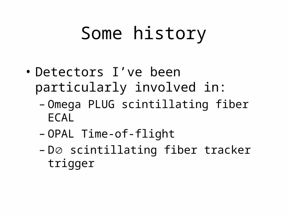
Some history
• Detectors I’ve been particularly involved in:– Omega PLUG scintillating fiber ECAL– OPAL Time-of-flight– D scintillating fiber tracker trigger

Ideas
• Concept #3: frankyaug05– Radially distinct calorimeter sections with fine
granularity
• Hermetic timing layer in ECAL– For eg. reactions like e+e- → this is very
useful
• Scintillating fiber tracking layers for track matching to ECAL and time-of-flight.

frankyaug05A radially staggered buildable analog calorimeter with exquisite granularity, with no cost optimization using Tungsten. B = 3T.
50 GeV photon
With M. Thomson. Acknowledgements to N. Graf
EM Barrel 1: 2.10 10 0.5 Si 2.5 × 2.5 × 0.32
EM Barrel 2: 2.13 10 0.5 Si 10 × 10 × 0.32
EM Barrel 3: 2.16 20 0.5 Sc 20 × 20 × 2
HCAL: 2.255 50 2.0 Sc 40 × 40 × 2
R(m) Nlayers X0 Active Cell-size (mm)
Choices made based on current R&D work, driven by making a sensible, robust design with aggressive performance and minimizing Silicon area in a GLD-scale detector.
Expect: E/E = 11%/E at low energy
(W was cheaper in 05..)
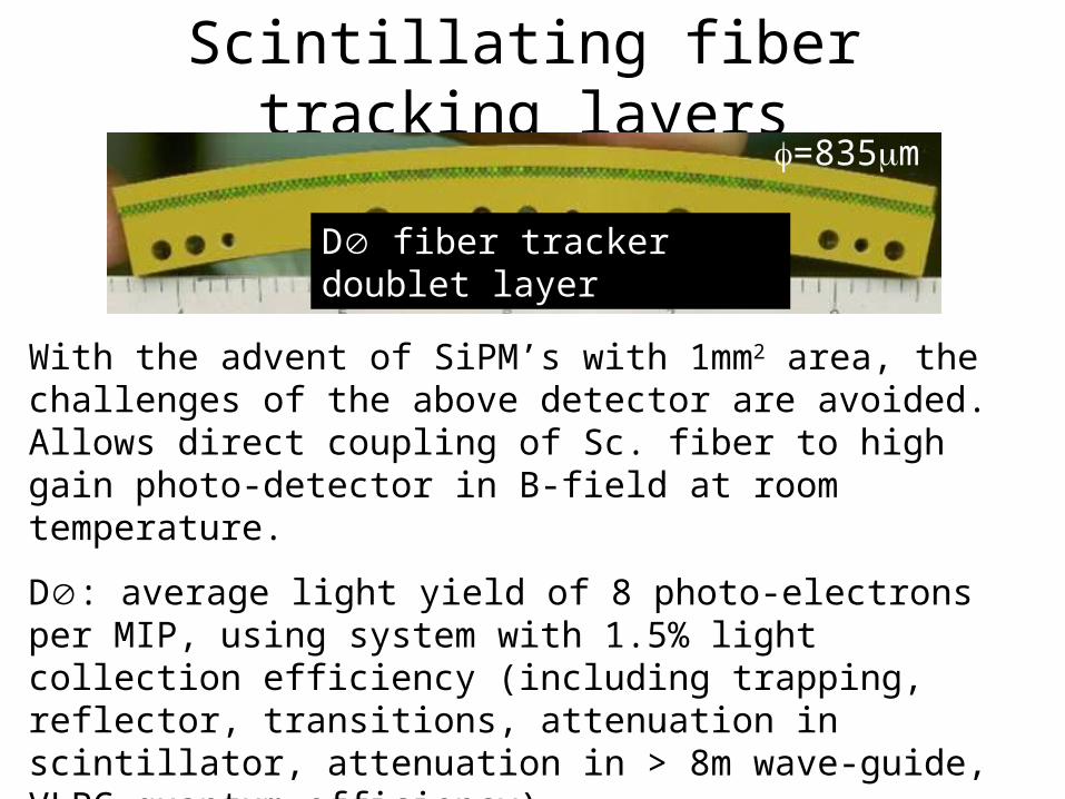
Scintillating fiber tracking layers
D fiber tracker doublet layer
With the advent of SiPM’s with 1mm2 area, the challenges of the above detector are avoided. Allows direct coupling of Sc. fiber to high gain photo-detector in B-field at room temperature.
D: average light yield of 8 photo-electrons per MIP, using system with 1.5% light collection efficiency (including trapping, reflector, transitions, attenuation in scintillator, attenuation in > 8m wave-guide, VLPC quantum efficiency).
With same fibers and 1.6m length expect 50 photo-electrons (L+R) with 65% PDE MPPC-100. Standard fibers > 3.5m
=835m

SiPM’s
• Noise not a major issue with coincidences.
• Dynamic range (100 pixels) and PDE of 65% of MPPC-100 is well adapted to 1mm fibers.
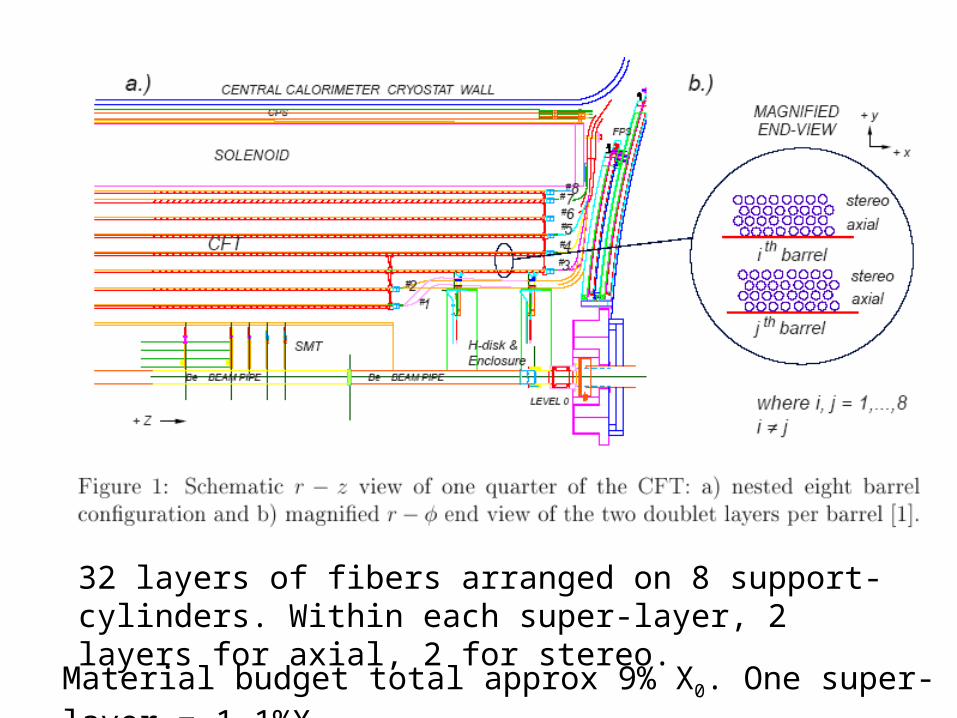
32 layers of fibers arranged on 8 support-cylinders. Within each super-layer, 2 layers for axial, 2 for stereo.
Material budget total approx 9% X0. One super-layer = 1.1%X0
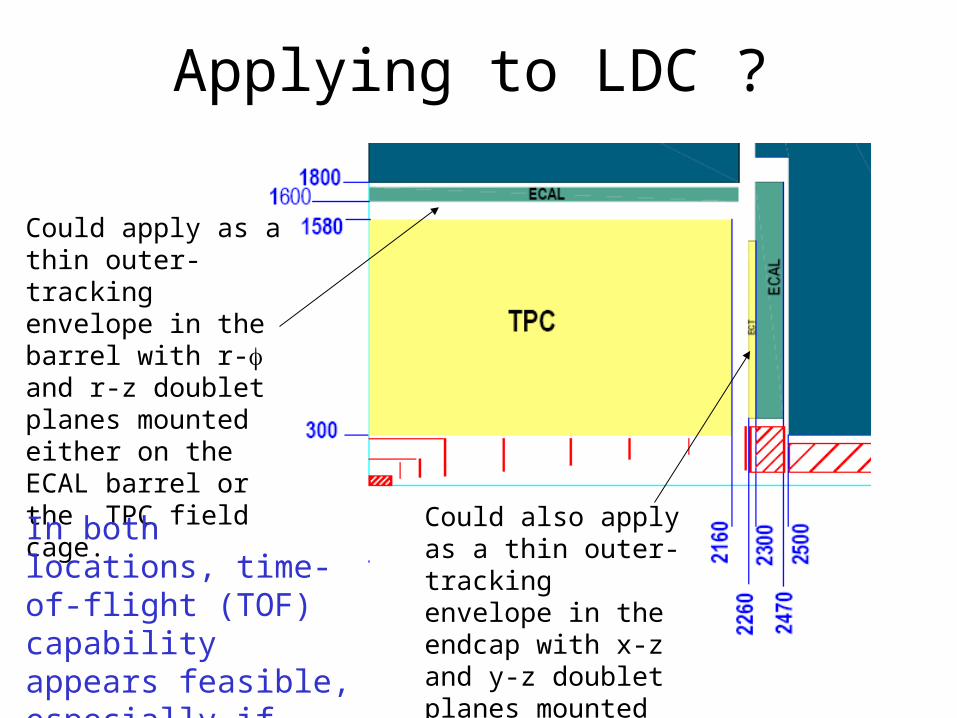
Applying to LDC ?
Could apply as a thin outer-tracking envelope in the barrel with r- and r-z doublet planes mounted either on the ECAL barrel or the TPC field cage.
Could also apply as a thin outer-tracking envelope in the endcap with x-z and y-z doublet planes mounted on the ECAL endcap
In both locations, time-of-flight (TOF) capability appears feasible, especially if both ends of the fibers are read-out.
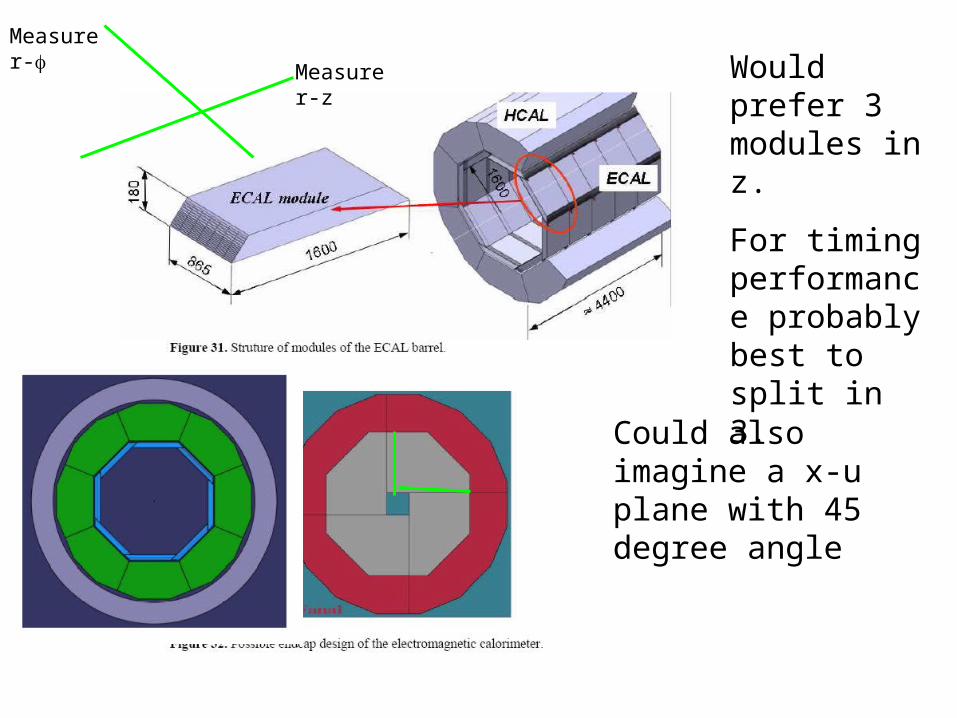
Would prefer 3 modules in z.
For timing performance probably best to split in 3.
Could also imagine a x-u plane with 45 degree angle
Measure r-z
Measure r-

Doublets 101
2 4
1 3
pitch
With sufficient light budget, doublet layer leads to 4 ≈ well defined regions per pitch unit (A, B, C, D) with approximately the same width. So intrinsic resolution is about (pitch/4)/12 assuming no cross-talk and high efficiency.
With only a few layers, need redundancy in case of single dead channels.
So prefer to read-out both ends of the fiber IF it can be done easily.
This lends itself to a classic TOF-like application too.
A B C D
The D scheme: pitch=960m, leading to r- = 90 m (test-beam)

Achievable Performance ?
• Assuming doublet arrangement for each plane with redundant readout, expect 100% efficiency per coordinate, and high efficiency for precise pitch/4 effective cell size.
• Geometries with vernier-style readout can be considered using the measured light output per layer.
D basically achieves pitch/10 = 100 m for these 775 m active diameter fibers with only 8 photo-electrons per MIP.
Ultimate performance limited by fiber placement errors in the ribbon at the ≈ 20 m level
For LDC, shorter fibers, flat planes, no light-guides => estimate 80 m resolution for both r- and r-z (barrel)
or for z-x and z-y (endcap).Square is probably best for this.
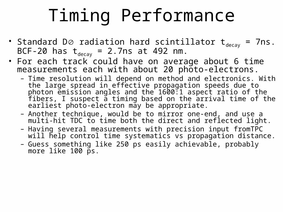
Timing Performance• Standard D radiation hard scintillator tdecay = 7ns. BCF-20 has tdecay
= 2.7ns at 492 nm.• For each track could have on average about 6 time measurements
each with about 20 photo-electrons.– Time resolution will depend on method and electronics. With the large spread
in effective propagation speeds due to photon emission angles and the 1600:1 aspect ratio of the fibers, I suspect a timing based on the arrival time of the earliest photo-electron may be appropriate.
– Another technique, would be to mirror one-end, and use a multi-hit TDC to time both the direct and reflected light.
– Having several measurements with precision input fromTPC will help control time systematics vs propagation distance.
– Guess something like 250 ps easily achievable, probably more like 100 ps.

Channel Count
• Barrel (r-doublets per octagon. – => 50 k fiber ends * n_modules = 150k (for n=3)
• Barrel (r-z). 4400 doublets per octagon. k fiber ends
• Endcap (x-z). 1200 doublets per quadrant– y-z. 1200 doublets per quadrant– => Total of 38k fiber ends.
• In total 333k fiber ends. (only 3.3% of GLD ECAL!)• So, may need to decide what level of redundancy, position
precision and time resolution we can afford and need– But given developments in SiPM’s it is probably not a show-stopper.
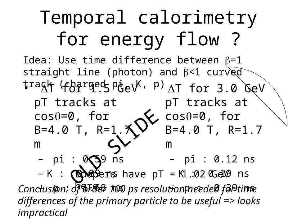
Temporal calorimetry for energy flow ?
• T for 1.5 GeV pT tracks at cos=0, for B=4.0 T, R=1.7 m– pi : 0.59 ns
– K : 0.89 ns
– p : 1.68 ns
T for 3.0 GeV pT tracks at cos=0, for B=4.0 T, R=1.7 m– pi : 0.12 ns
– K : 0.19 ns
– p : 0.39 ns
Idea: Use time difference between =1 straight line (photon) and <1 curved track (charged pi, K, p)
Loopers have pT = 1.02 GeV here.
Conclusion: of order 100 ps resolution needed for time differences of the primary particle to be useful => looks impractical
OLD SLIDE

Particle ID
=1, flight time for 2m is 7 ns.
So expect resolution on 1/ for t=100 ps of about 1.5%.
1.5 GeV gives pion/kaon T of 300 ps.
So expect 3 separation pi/K separation at 1.5 GeV which complements dE/dx nicely.
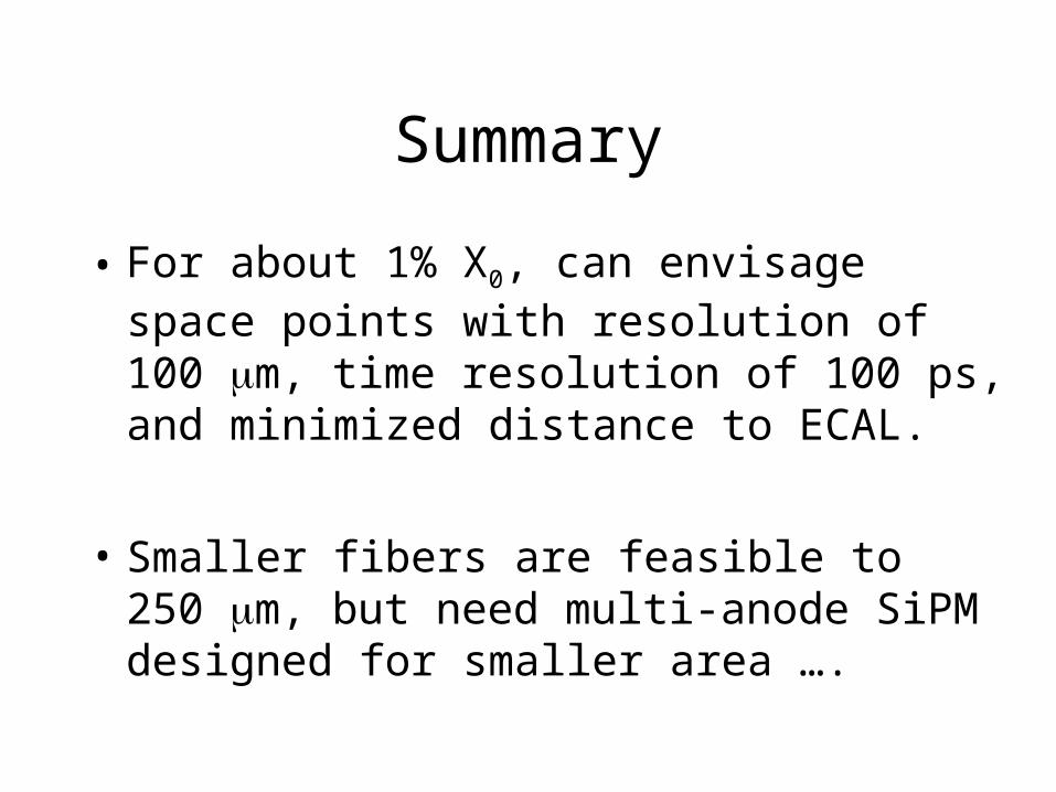
Summary
• For about 1% X0, can envisage space points with resolution of 100 m, time resolution of 100 ps, and minimized distance to ECAL.
• Smaller fibers are feasible to 250 m, but need multi-anode SiPM designed for smaller area ….