gr 1983·9730 sound...sound-measuring-equipment line is the sound· level meter (slm). the 1983...
TRANSCRIPT

IHSTRUCTIOH MAHUAL
GR 1983·9730 SOUND-LEVEL METER
(GR 1983-9910 and -9915 SLM Sets)
This instrument is capable of making soundlevel measurements required under Part 1910.95 " Occupational Noise Exposure," (Dept. of Labor) of the Code of Federal Regulations, Chap. XVII of Title 29 (36 F .R. 7006) .
Certified by California Highway Patrol as meeting ANSI S1.4 Standards.
These instruments carry U.S. Bureau of Mines, Mining Enforcement Safety Administration ,approval for use in methane-air mixture only. Approval Number 2G-2793.
1983-01 50-A
July 1976
ID-6312
Copyright 1976
m..GenRad CONCORD , MASSACHUSETTS 01742

POWER ON /OFF AND BAT. CHECK SWITCH
\
COIN SLOT SCREWS TURN CCW TO OPEN INSTRUMENT FOR BATTERY REPLACEMENT
INDICATOR 50-<:IB RANGE
METER RESPONSE LABEL
DC OUTPUT JACK
TRIPOD MOUNT
AND ACCESS TO
CALIBRATION ADJUST
CONTROL
Figure 1-1. Sound-Level Meter Controls and Indicators.

WARRANTY
Th1s product is warranted to be free from defects 1n
ma tenal and workmanship and, when properly used , will
perform in accordance w1 th specifications. Any GR manu
factured tnstrument. module or part, found not to rneet
th1s standard wi th in a period of one year after ong1nal
sh 1pment wi ll be repai red or replaced at no charge when
returned to a GA service facili ty GR poli cy 1s to ma inta in repai r capabil itY for a period of
ten years after the or iginal shipment and to make this
capabili ty ava ilab le at t he then preva ili ng schedule of charges for an y product returned to a GR service facility .
Changes in t he produc t not approved by G R sha ll void
th•s warranty. GR is not l iable for consequential damages.
Th is warr~ n ty is in lieu of all other warran ties. expressed
or 1mplied. including, but not l1mited to, the implied war
ran t• es of mercl .antabl lity and fitness for a particu lar pur
pose .
The information in this manual is in compliance with Section 1036 of the Exhaust System Certification Law of the California Highway Patrol, effective January 1, 1971, and the G R 1983 has been certified by the California Highway Patrol as meeting ANSI S1.4 Standards for SoundLevel Meters.
1983CONDENSED OPERATING INSTRUCTIONS
• Remove and retain protective cap on microphone.
• Slide switch toward base of instrument and observe that meter reads above battery line. If it does not, replace battery. (See para. 3.1 .)
• Slide switch toward microphone to turn on meter . A slight inward pressure at mi crophone end of switch locks instru ment in ON position . Depressing other end of the switch releases the lock.
• Point the microphone at right angle to the direction of the noise path, keeping your body out of the path . (See Fig . 3-2).
• Peri odically calibrate the sound-level meter with a GR 1562 or 1567 SoundLevel Calibrator .
CAUTION If continuous noise exceeds 115 dB (A) slow, immediate use of protective ear muffs or plugs is indicated .
Battery Installation See page 9.

SPEC I F ICA Tl ONS
STANDARDS
Meets the following: ANSI Standard Specification for Sound-Level Meters S1 .4-1971, Type S2A; I EC Recommendation Publication 123,1961, Sound Level Meters.
SOUND LEVEL RANGE
Measurement Range: 70 to 120dB re 20 1JN/m2 (micropascals, IJPa).* Input preamplifier including microphone (pr ior to weighting network) wi l l hand le sound pressure levels of at least 145dB at any frequency in the range between 20Hz and 1OkHz.
FREQUENCY RESPONSE
A weighting in accordance with above standards.
DETECTOR AND METER CHARACTERISTICS Meter : Single 70 to 120-dB sca le, linear in dB. Detector Response: Slow, in accordance with above standa rds_ T rue RMS, with crest-factor capac ity of X5 at fu ll sca le. (Jumper on etched board al lows se lect ion of fast response in acco rdance with standard.)
MICROPHONE
Ceramic microphone with flat randomincidence response_
D-C OUTPUT
Behind 100 kD, 0.25 Vat fu l l scale (120 dB). Output can be short circu ited w ithout degrading SLM performance.
Specifications (continued)
CALIBRATION
Can be pressure calibrated at 1000 Hz with 1562 or 1567 Sound-Level Calibrator.
POWER
One 9-V battery (Burgess 2U6 or equivalent) produces approximately 60 hours of continuous operation.
SUPPLIED
Battery Screwdriver Miniature plug to connect to out put Carrying pouch
ENVIRONMENTAL
Temperature : Operating, - 10 to +50° C; -40 to +60° C storage, with batteries removed. Humidity : Operating, 0 to 95% R H. Vibration : Comp lete inst rument able to withstand .030 in. peak-to-peak vibration 10 to 55 Hz. Magnetic Fields. Reads less than 70 dB when placed in a 50 to 60Hz magnetic field of 25 oersteds.
MECHANICAL DATA : Width: 3.50 in., 88.90 mm, Height: 7.950 in., 201.9 mm, Dept h: 1.87 in. 47. 50 mm, Net Weight : 12 oz., 0.34 kg.
• R ef : "The International System of Un it s (SI) " , U.S. D ep t. of Com m erce, National Bureau of Standards, NBS Special Publicat i o n 330. SD Cat. No. C 13. 10 :330/2, U.S. GPO, Wash. , D.C., 20402.
U.S. Patent No . 3 ,681,618

1. Sound Level Calibrator (Bu Mines Approved)
2. Carrying Case 3. Remote Cable 4. Microphone Windscreen 5. Tripod 6. SLM- 1983
GR 1983-9910 SLM Set
(GR 1983-9915 Set same less items 3 and 5)
--
Section 1 INTRODUCTION
1.1 GENERAL Sound (or noise) is basically a rapid varia
tion in atmospheric pressure, and a sound-level meter (SLM) is an instrument that measures weighted sound pressure-level. A measurement of sound is accomplished by changing a noise into an electrical signal and displaying it on an indicator in terms of decibels (dB).
The apparent loudness that we attribute to a sound varies not only with the sound pressure but also with the frequency (or pitch I of the sound. How it varies with frequency depends on the sound pressure . This effect is taken into account to some extent for pure tones by "weighting" networks included in the SLM.
The above points are illustrated briefly in other literature available free from GenRad. For a more comprehensive work on noise, our Handbook of Noise Measurement for $7.50 contains 328 pages of detailed information on how to solve your noise problems.

2
1.2 PURPOSE The bas1c Instrument of the General Radio
sound-measuring-equipment line is the sound· level meter (SLM). The 1983 (F1gure 1·1) is a Ty pe S2A SLM. A Type S2A instrument is a special-purpose SLM, A-weighting only, meet· ing the requirements of Type 2 as specified by the American National Standards Institute (AN SI) standard specification, S1.4· 19 71, for sound-level meters. It also meet requiremen ts of IE C ( Internati onal Elect rotechn ical Com· mission ) specifi cat ion R-1 23 (1961).
The chief use o f t he 1983 SLM 1s for noise measurement, to insure compliance with OSHA (Occupational Safety and Health Act o f 1970, 84 Stat . 1593). Refer to para 3.9 for a discussion of this law.
Measuring vehicle noise is another applica· tion for th e 1983 Sound· Level Meter. Refer to para 3.10 and 3-14 f o r details of the measurement.
1.3 DESCRI PTI ON 1.3.1 General
The instrument 1s housed in a high·1mpact Lexan molded case that is shaped for comfor· table hand-held operation and tapered at the microphone end to minimize the effect of case diffractiOn. It cons1sts of the follow1ng elemen ts: a microphone to pick up sound; an A-weight· ing network to adjust frequency characteris t i c, an am plifie r, a w ide-range true-rms detector circuit, a logging circuit to make the meter scale and d·c output linear 1n dB, and an Indicating
meter. It covers the sound-level range from 70 to 120 dB (re 20 !-LPa) on a single range and can be internally set to have either a slow or fast meter characteristic .
The amplifier and detector are capable of handling crest factors up to 13 dB above full scale . Thus , the total dynamic range for sine· waves is 63 dB (d·c output versus sound·pres· sure-level input), all on one scale.
Figure 1·2 shows a polar plot of the angle· of-incidence responses and Figure 1·3 shows the frequency response as a function of inci ·
dence of the S LM. The microphone used is a lead·zi rccinate·
titanate ceramic microphone that couples into the Y,- in . coupling adaptor used with the 1562 or 1567 Sound-Level Calibrators . The following features make it excellent for sound·
level measurements:
1. A frequency characteristic carefully controlled to give flat response to sound waves of random incidence at frequencies from 5 Hz
to 9 kHz.
2. Rugged, dependable design capable of withstanding wide climate changes (from -40° to +65° C, from 0 to 100% relative humi· dity), and able to withstand large amounts of vibration and shock (up to 60 g of acceleration).
3 . Low temperature coefficient of sensiti· vity (.01 dB( C) gives minimal change in output voltage from - 10° to +45° C.
4. Unplugs for remote use.
3

o·
~
}\ Figure 1-2. Directional response patterns of the 1983 SLM.
.,
.. 1-
• 2
-I
-2
_, - 8
4
TYPE ]SPECIFICATION
.----l I - v FREE •ofLO PEhPENOoC~-1/ ~ INCIOENICE 10°)
~ ~A'\' --i----- RANDOM INCIDENCE f1<f!
~
I 1K
I 2K
FREOUENCV IN Hz
I I
SK
Figure 1-3. Typical frequency response characteristics of the 1983 SLM.
1\ I I 7K IOK
1.4 ACCESSORIES SUPPLIED
The following accessories are supplied: 1. Vinyl carrying pouch - (P/N 1983-0401 ). 2. Wrist Strap- (P/N 1981-0410) 3. Screwdriver- (P/N 1565-0440). 4. Battery- (Burgess 2U6 or equal) 5. Microplug- Switchcraft type 850-P2 6. Battery sleeves ( 3) to cover battery 7. Microphone cap- (P/N 1972-7410) 8. Meter response label - (P/N 1983-0430)
The following accessories are supplied with the 1983-9910 Sound-Level Measuring Set* in addition to the above:
1. Sound-Level Calibrator- (P/N 1567-3000)
2. Adaptor 1/2 in.- (P/N 1562-6130) 3. Battery - (Burgess 2U6 or equal) 4. Microphone Wi ndscr~<en 1 /2 in 5. Carrying Case- (P/N 1983-2101) 6. Extension cable- (P/N 1933-0223) 7. Tripod- (P/N 1560-3590)
1.5 ACCESSORIES AVAILABLE Foil owing are some of the accessories
that are available for use with the SLM (con· suit the GR catalog information fer others):
1. Type 1567 or 1562 Sound-Level Calibrator- for accurate field cali-bration of microphones and sound-measuring instruments. Requires 1 /2-in. microphone coupling adaptor, (P/N 1562-6130).
2. Tyoe 1560-9590 Adjustable Tripod. 3 . GR microphone windscreens, four
per set, (P/N 1560-9522) for reducing the
•1983-9915 Set same less items 6 and 7. 5

effects of wind noise and protecting t he microphone.
4. Carrying Case- (P/N 1983-2101) holds SLM Calibrator 1567 or 1562 and other accessories.
5. Adaptor cables: Type 1560·P77, microplug to 3/4-in.·spaced banana-plug pair (P/N 1560·9677); Type 1560-P78, micropl ug to standard 1/4-in. phone pi ug (PIN 1560-9678): Type 1560-P79, microplug to BNC plug (P/N 1560-9679); Type 1560-P80, microplug to standard 1/4-in. phone jack (P/ N 1560-9680).
6. Small remote microphone with cable and ear loop for measuring noise on worker or through hearing protectors (P/N 1954-9640).
Section 2 INSTALLATION
2.1 GENERAL The sound-level meter should be stored
in the vinyl pouch (supplied) when not in use.* It can be carried conveniently at waist level by slipping your belt through the loop on the back of the pouch. The protective cap should be in place over the microphone except when the S LM is in actual use.
2.2 OPERATING ENVIRONMENT The SLM operates over the range of en
vironmental conditions that are normally en-
6 • Does not apply to 1983-9910 and 9915.
countered in industrial applications. It is not recommended that the SLM be stored in a hot place with the battery installed, since the battery life is quickly degraded. The battery has a protective sleeve around it to prevent acid leaking into and damaging the instrument .
CAUTION Batteries should be removed before storing the SLM for ex tended peri ads , to avoid corrosive battery leakage.
2 .3 TRIPOD MOUNTING Any tripod that has a standard 1/4·20
thread will fit the insert on the base of the instrument case. To use the tripod available from General Radio (P / N 1560-9590) the following procedure should be used:
a. Tilt sleeve adaptor (head) to appruxlmately 70° from verti cal, i.e., from the axis of the tripod center post.
b. Remove any sleeves ·or adaptors from the swivel top.
c. Remove each sleeve after loosening its knurled clamping nut Y. turn.
d . Tighten the smaller clamping nut gently, by hand . (If inadvertently removed, be sure to replace each nut with its split locking ring, oriented so that the beveled edge is down.)
e. Screw instrument onto top stud, approx. 4 turns. Unscrew slightly, if necessary, to orient microphone upwards .
f. Turn the smaller clamping nut snugly against the chassis, to clamp instrument.
7

8
2.4 MICROPHONE WINDSCREENS . Microphone windscreens are used to re·
duce the effects o f ambient wind no1se . Wind flowing across the surface of the mi· crophone generates low-frequency no1se, wh1ch can lead to erroneous measurements. The wmdscreen also protects the m1cro· phone from accumulations of vapor and dust m the work environment.
Th is accessory fits snugly over the micro· phone. It 1s made of ret icu lated polyure· t hane foam and ca n be conven iently removed and washed, o r re pl aced, i f it becomes soiled .
Th e wi ndscreens are available 111 packs o f f our, P/ N 1560·9522, to f1t y,.,n. m1cro· ph one.
2 .5 OUTPUT CONNECTOR It may be desirable to p lot sound level
versus t1me on a chart recorder. T herefore, a connec t or at t he base o f the Instrument IS available t o supply a d-e voltage proportional to meter response. This voltage is even more accurate than the meter read 1ng, accurate to typ1cally ±0.2dB over the range of 70-1 20 dB, compared to the 11 4·d B reference. A Switchcraft type 850-P2 (microplug) connector IS supplied with t he SLM to complete th1s end o f a patch cord. The other end can be term1nated w1th whatever connector IS necessary. (Para. 1.5 re fers to standard adaptor cables that are available.) The output voltage is 250 mV behind 100 kn source 1mpedance. Refer to para 3.12 for recommended d-e recorde rs.
Section 3 OPERATING PROCEDURE
3.1 BATTERIES One 9·V, carbon-z,nc, transisto r battery
(2U6 or equ1valentl 1s suppl1ed and should be checked each time the 1nstrument 1s used. To check the batteries, sl ide t he power sw1tc h down (F1gure 1- 1 ). The meter shoul d move to or above the reg1on marked BATTE RY OK. If 1t does not, the battenes must be replaced.
Battery l ife at 21°C is typica lly 60 hou rs. T able 3-1 gives the battery I ife that can be expected at various temperat u res.
Table 3-1
1983 BATTERY LIFE VERSUS TEMPERATURE Temperature (0 F) (OC)
14 - 10 30 0 70 2 1
115 43
Life (Hours)
34 45 60 60
To ensure an accurate battery check, t he test should be made at the tempe rature at wh1ch measurements are to be made.
To replace the battery, first turn the instrument off. T hen, using a coin (or screwd river) , unscrew the two la rge captive screws on the face of the meter. Then pu l l the meter out of the case, being careful not to pull
9

10
hard on the microphone cable. Pull the battery out of the molded plastic holder, pull off the protective sleeve, and disconnect the battery from the clip. Replace with Burgess 2U6 , Eveready 216, or equivalent.
If battery acid has leaked into the pro· tect1ve sleeve, discard and replace with new one (three are supplied with the instrument , additional units available thru GR service) (P /N 5451·0100). Mount the sleeve (pre· vents damage to instrument should battery leak) and put the battery back in the holder as shown in Figure 5-4. With switch in OFF position and the switch on the etched board centered, place the meter back into position in the case and tighten the screws. Again, check the battery before using the instrument.
3.2 CALIBRATION
A quick, reliable sound-pressure level calibration can be performed at 1000Hz by means of a GR 1567 or 1562 Sound· Level Calibrator. The calibrator, like the SLM, is small, lightweight, and battery operated, making it ideal for field use.
The procedure is as follows : a. Slide the power switch to the ON
position . b. Turn the calibrator on and , if using
the 1562, set the calibrating frequency to 1000Hz.
c. Place the calibrator, with the Type 1562- 6130 Adaptor (1 /2 inch) installed , over the microphone of the SLM (as in Figure 3-1).
Figure 3·1. Calibrator mounted over SLM microphone.
d. Observe the SLM meter ind1cator to be 114 +0.5 dB. If the meter Indicator falls outside th1s range, adjust the CAL control through the tnpod mounting hole to obtam a 114-dB 1nd1cat1on. (Use the screwdnver supplied - P/ N 1565-0440.)
If checkmg frequencies other than 1000 Hz, using the 1562 Sound· Level Calibrator, remember the A-weighting network will change the CA L point. Table 3·2 shows the correct nominal value with allowable toler· ance according to the Type 2 standard.
11

12
Table 3-2
CALIBRATION TOLERANCES AT OTHER THAN 1000Hz
Nominal Allowed Frequency Meter Reading Tolerance
(Hz) (dB) (dB)
125Hz 97.8 dB ±1.5 dB 250Hz 105.4 dB ±1.5 dB 500Hz 110.8 dB ±1.0 dB
1000Hz 114.0dB ±0.5 dB 2000Hz 115.2 dB ±2.0dB
3.3 BASIC OPERATION Check the battery as in para 3.1 above .
Slide the power switch to the ON position. (Push forward with the thumb on the front part of the switch, until it detents into position.)
Stand with the instrument in front of you, w1th the sound coming from the s1de. Point the microphone in a direction perpen dicular to the no1se path, keeping your body out of the path (see Figure 3-2).
When using fast meter speed, an average level should be estimated if the meter pointer fluctuates by 3 dB or less. Refer to para 3.5 for converting to SLOW or FAST meter speeds .
It IS important to use good technique when measuring sound level . There is no harm done by getting too much information in the field. But if you return with skimpy information, just sound-pressure level, for example, you may have to return for more data. It is a good idea to make up a data form similar to that in Figure 3-3. This pro-
Figure 3-2. Proper positioning of meter with respect to noise source.
vides a remmder for the various checks and data, mcluding a sketch of the site. In an outdoor environ me<' t, ground surface and wind can affect the measurement.
When making measurements outdoors, it is important to use a windscreen (P/ N 1560-95221 . The windscreen has negligible effect on frequency response (refer to Figure 3-4).
To turn the 1983 Sound- Level Meter off, push down on the bottom part of the switch . It will detent off.
3.4 A-WEIGHTING NETWORK A-we1ghting is most commonly used for
measuremen t o f motor vehicle, applicance, office o r plant noise. Except for impact
13

Form OA.Tf 1/ a./"q "'ET(It• r.s-4? Plant-Noise Survey
OIAGA.o•• ~8!')
l0CAT1Qtj a.., ,f4,~ f, ~ = = c-------------, Fltor, C.,J. It. B....,tl ,,., d.rc. ..
1\ilJ"'Btll 01 P!IISO'II"'fl ~~POSED 1 .,.E.&.III"GE"II"II01£C110'<' ~D
o•EIIATOR J •l. L...C.O","r
SIG'<ED ?.Gtf~
Lee.•t••" .. I .. • 2 ... e.rt. o.,
p
" art S , ,s
Q R •s ''-S , ".; .,
·~
1 S(.ICI & "'!.•(•"""'· SCOO'o "' T(~ At§I'O"st· 10• C Olll(."l'~'• "'SI AtVOJoSJ.O()fOo-ACI .. O•!>t
J IUA"< ATT(NUA I OA ~N<'I tO <..H
SO::ACI AHO<"{; oOII !tl 10001 •uu K•UOQIO ...... ClNQISl
o .o.otl•t•OIN(,IO•NOis.fiii .. GtO GlTTOI•col
~~1] (11,ke 5 1 Z" ofl' fltJor
'<01£5 --opr:..r..C•r ~oc.s. bade uo.d 4rck bt.t ... tc..o '"""'"" ' "" -St.T·vf' t,.c, ,..,.of,...,,; l .. , r-... 1 ,...,,. ....,, ,..,, - S ... ,. ., rc.> .. c Q, ...,J tv~.,:rc.. ,.\, .. \ - ZS e,.o..l. lc.J/<1•'1-o.v~c.. Wor~Tu..'c. Ui rJ. . - 13.-t.lr, ,...,u. . ,.,~ "•'" .J..-6~ o" cJvr .... 3 ,, , t ,.J P"''r ,1 ,..,,
0 '
T ·~~: ·-~ ,.~.~':', o -4- : •• ;:. f'··;: ..... p
NON'
t-
,, t.~ ... , , ___ , .. ~·~ r ... :~ " . 92 r'3 t .... u J 4,.,,.,.,zu to..(..~ 1.8? 6 • 1
• ::.~ 1..1,_ t . ... c.) o..~ i ""-'""'tu~ . 80 8 .10
90 ~t~-- Oru.J.: /.,,..;., e.Aolc. '·'t·~r- 'f :so t . t ... / 4 . s 3 ~Nv
~;~:[:\:~E:.~~:~~~;5~~}~~~·~1~ I M~ - 101 J8(e)
A£·~~;;'~~~o:\~~·N;·~·• t-t ... ve ul• ~1 eca.,.. pr.t&<:.t .• ,.
Figure 3-3. Completed form of a plant-noise survey.
14
z z l
Figure 3-4. Changes in sensitivity caused by use of the microphone windscreen (typical).
noise, Federal Regulations, such as the OccupatiOnal Safety and Health Act,requ~re use of th e A network (hence, the symbol "dB(A)" for sound-leve l decibels on the A-scale). • Vehicle and truck noise, under the No1se Control Act of 1972,also requ~re A-weighting.
The frequency response for the A-weighting charactenstic is shown in Figure 3-5 . The A-vve1ghting characteristic discriminates heavily aga1nst low-frequency sound to g1ve an md1cat1on closely correlated with subjective estima tes of loudness , annoyance and speech Interference .
• See Guidelines To Tile Department of Labo r's Occupational Noise Standards I Bull etin 334 , Revised 1971 ), copies available from U.S. Department of Labor, Occupational Safety and Health Administration, Washington , D .C. 2021 0 ; American Conference of Gove rnmen tal Industrial Hv · gienists ·' Threshold Limit Values of Physi cal Agents."
15

16
0 I I I ~
0 1 I
I
o I i i l i l I I iII
o I I i
1/ I 0
-· 0
- 50 10 zo 50 100 200 500 1000 2000 5000 10,000
FREOU£NCY 4 Hz
Figure 3-5. A -weighting characteristic showing 'he deemphasis of low-frequency sound consistent with human noise perception .
3.5 METER RESPONSE The 1983 Sound-Level Meter has both
FAST and SLOW meter response. However, it is meant to be left at one response and labeled. All OSHA measurements require slow response. and some vehicle noise measurements require a fast meter response.
The 1983 is shipped 1n the SLOW response position and labeled SLOW, as shown in Figure 1-1. In order to change it to the FAST response, proceed as follows :
a. Turn the instrument off. b. Using a coin or screwdriver, unscrew
the two large captive screws on the face of the meter.
c. Pull the meter out of the case, being careful not to pull hard on the microphone cable.
d. Remove the jumper from the S position (see Figure 5-6 upper right quadrant) and plug it into the F positinn.
e. With switch in OFF position and switch on etched board centered, place meter back tnto position in case and tighten
screws. f. Take the protective backing off the
label marked FAST (P/N 1983-04301 and place it into position over the SLOW. This is important, si nee it lets every operator know what response has been selected.
If in doubt about the response previously selected, turn the instrument on. give the instrument a loud transient, such as whistling directly into the mike, and note the time for the needle to decay 10 dB. It should take about 2 seconds for SLOW and about 0.3 to 0.4 second for FAST.
3.6 OVERLOAD PREVENTION The amplifier and detector circuit in
the 1983 SLM is capable of handling signals linearly more than 10 dB above full-scale meter indication and peaks "on sp1ked signals" 13 dB above full scale.
The FET tnput stage, before the Aweighting networks is capable of handling signals up to 145 dB (25 dB above full scale). such as occur when analyzing noise signals with large low-frequency components .
17

18
3 .7 EFFECT OF THE OPERATOR
When the sound 1s comtng matnly from one directton, the sound-level reading may be somewhat affected by the relattve posit ions of instrument and observer. The S L M should not be held between the observer and the source , wtth the mtcrophone pomted toward the source of the sound, although thts seems the most logtcal manner. Thts posttton gtves a marked increase m the response at htgh frequenctes. The observer, facmg the sound from directly behtnd the mstrument, acts as a reflector to produce errors of several dB 1n the frequency range above 100 Hz.
A more un1 form f requency response IS obtamed wtth the meter in front of the observer, but wtth the sound graztng the microphone (comtng f ro m t he stde, rat her than from the front). When out of doors, hold the tnstrument with the mtcrophone potnttng upward, (to avotd Interference from reflected htgh frequenctes) and as far from the body as 1s conventent. Do not potnt the mtcrophone toward a source of back · ground noise (any source other than the one bemg measured).
The sound -level meter can be moun ted on a tripod (see para 2.3) to reduce further the ef fects of the observer's presence. His positton should be stmilar to that for handheld operation; a line between the observer and the tnstrumen; should be approxi mately perpendicular to a li ne from the tnstrumen t to the sound source.
3.8 BACKGROUND NOISE Meas u rements shoul d be m ade wtth as
ltttle bac kgrou nd notse as possi ble. For all w eightings the background level sh oul d be at leas t 10 dB below the total measured level . When thi s cann o t be done, apply the co rrec tt ons gtven 1n Ftgu re 3-6 .
3.9 OSHA REGULATIONS Th e Occ upational Safety and Hea lth Act
o f 19 70 (84 Stat. 1593) se ts l1m1ts f o r permi ss1b le exposure t i mes fo r the various level s of noise shown in Table 3-3 . The . no ise 1s meas ured wtth a SLM or No ise Dosi meter with " A " w etghting and "slow"
i ~
~ " ~ c
~ ... ~ "' Cll
g
71 6
\ 4
21 I I
I
\ I
l I
'\j i
""' I
........ r----~
I
~ --r t--ffi u I 3 • 5 6 7 8 9 10
~ dB DIFFERENCE BETWEEN TOTAL NOISE AND BACKGROOND ALONE
Figure 3-6. Effect of background noise on measurements.
19
20
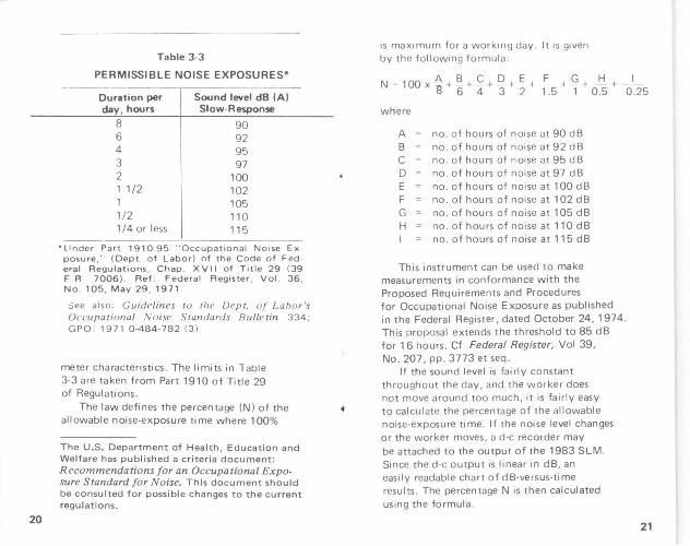
Table 3-3
PERMISSIBLE NOISE EXPOSURES*
Duration per day, hours
8 6 4 3 2 1 1/2 1 1/2 1/4 or less
Sound level dB (A) Slow-Response
90 92 95 97
100 102 105 110 115
'tinder Part 1910.95 " Occupational No1se Ex posure: · (Dept . of Labor) nf the Code of Fed · eral Regulations . Chap . XVII of Title 29 139 F. F'I 7006) . Ref : Federal Register, Vol . 36 , No . 105, May 29 , 1971 .
See also: Guidelines ru rl1e Dept. of Labo r's Occupational Noise Standards Bulletin 334; GPO: 1971 0-484-782 13) .
meter characteristics. The limits in Table 3-3 are taken from Part 1910 of Title 29 of Regulations.
The law deli nes the percentage (N I of the allowable noise-exposure time where 100%
The U.S. Department of Health, Education and Welfare has published a criteria document: Recommendations for an Occupational Exposure Standard for Noise_ This document should be consulted for possible changes to the current regulations .
1s max1mum for a working day. It is given by the following formula ;
N = 1 00 A + §_ + ~ + Q + £ + £._ + Q + _li + _ _!_ X 1l 6 4 3 2 1 .5 1 0.5 0 .25
where
A no. of hours of noise at 90 dB B no . of hours of noise at 92 dB C no. of hours of noise at 95 dB D no . of hours of noise at 97 dB E no. of hours of noise at 100 dB F no. of hours of noise at 102 dB G no . of hours of noise at 105 dB H no . of hours of noise at 110 dB
no . of hours of noise at 115 dB
This instrument can be used to make measurements in conformance with the Proposed Requirements and Procedures for Occupational Noise Exposure as published in the Federal Register, dated October 24. 1974. This proposal extends the threshold to 85 dB for 16 hours. Cf Federal Register, Vol 39, No. 207 , pp. 3773 et seq.
If the sound level is fairly constant throughout the day, and the worker does not move around too much, it is fairly easy to calcul ate the percentage of the allowable noise-exposure time . If the noise level changes or the worker moves , a d-e recorder may be attached to the output of the 1983 SLM. Since the d-e output is linear in dB, an easily readable chart of dB-versus-time results. The percentage N is then calculated using the formula .
21

22
This is a time-consuming task, and it is more economical to use a noise dosimeter. such as the GR 1954 Noise Dosimeter, for the purpose. since theN is calculated automatically. If the allowable exposure is exceeded, the 1983 SLM is ideal for locating the source of noise. The SLM facilitates these measurements due to its inherent ease of use, since it has only one control, an ON-OFF switch, and a single 50-dB scale.
When measurtng noise for OSHA, care must be exercised , as the presence of a worker will affect the measurement result .
The correct procedure IS to remove the worker, s1nce body reflections do cause some error. However, this error 1s small if the worker's head does not block the source of noise. Table 3-4 shows errors for pink no1se measured 1n a reverberant room.
The-1983 can also be used 1n th1s way to find the optimum microphone placement for the remote microphone on the 1954 Noise Dosimeter. Measure the noise. with the worker removed as mentioned above. But, place the SLM 1n the position normally occupied by the worker's ear, then measure the no1se at several m1ke locations, with the operator present, at each ear, top of each shoulder, etc ., to find the spot g1ving a reading closest to the first or 1deal measurement.
3.10 VEHICLE REGULATIONS FOR TRUCKS The No1se Control Act of 1972, Publ1c
Law 92-574, 88 Stat. 1234, prov1des for noise-emissiOn l1m1tS for motor earners
Table 3-4
ERRORS IN RESPONSE TO PINK NOISE CAUSED BY A NEARBY PERSON, MEASURED
WITH "A" WEIGHTING
Error-dB( A)
Mic~~ Lac 00 900 180° 270° Average Near ea r +0.3 +0.2 -U.3 0.1
Near shoulder +0.7 +0.5 -0 .1 +0.3
In shi rt pocket +1.2 +1.0 +0.8 +1.4
Near hip +0.1 -0.4 -0.3 -0.7
engaged in interstate commerce. The effective date of the new regulation is October 1, 1974. Its enforcement will be carried out by the Department of Transportation .
The regulation as proposed will apply to
motor vehicles operated tn interstate commerce and weighing over 10,000 lbs . GVW. The following proposed standards* will apply to total vehicle no1se:
0
+0.4
+1.1
-0.4
1. 90 dB(A) at 50ft (15m) in speed limits greater than 35 mph (51 km/h)
2. 86 dB(A) at 50ft in speed limits equal to or less than 35 mph.
3. 80 dB I A) at 50ft on level streets in speed lim1ts equal to or less than 35 mph.
• Federal Register , Vol. 38, No. 144, pages 20102 -20107.
23

24
Table 3-5
ALLOWABLE VEHICLE NOISE L EVEL d B (A )
California Proposed Test Condition 1973 1975 1978 Federal
Below 35 mph* 86 86 86
Above 35 mph 90 90 90
New Vehicles above 35 mph 86 83 80
Stationary Run-up Test (Accelerate with transmiss1on in neutral)
'5 1 km/h
4. 88 dB(A) at 50 It under stationary run-up test.
86
90
88
More stringent requirements currently 1n force 1n California are given _in Table 3-5.
The pass-by tests should be measured with the sound- level meter mounted on a tripod using A-weighted FAST. (Refer to para 3.5 for chang1ng meter response.) The SL M should be 50 It from the center line of the veh1cle, see Figures 3-7 and 3-8. A booklet describ1ng procedures for mak1ng these measurements is available from Stemco. •
The Bureau of Mo tor Carner Safety has also set l1m1ts on 1n-cab sound levels t of 90 dB!A) measured at the driver's seating posit1on. Aga1n, A-weighted FAST is required.
'Truck Noise Contro l, Stemco Manufactur ing Co., Inc., Box 1989, Longview, Texas 75601. t Federal Ref!ister, Vol. 38, No. 2, pp. 800 and 801. Rev1sed November 8, 1973.
VEHICLE PATH
50'; 15m 10Q' ;3Qm
Figu re 3-7 Spat ial requirements for vehicle pass-by noise measurements.
VEHICLE PATH
• Body o t observer should be at a 45° angle to mH11m11& reflect iOns when the ca r IS 111 thll 50 POint
Figure 3-8. Obser ver and SLM placement for vehicle pass-by measurements.
25

26
The procedure for mak1ng this measurement is as follows:
1. Park the vehicle in a cleared location 50 It from any large reflecting surfaces.
2. Close doors, windows and vents and turn off all power accessories.
3. Place the dnver 1n the normal seated position and evacuate all occupants except the driver and the person conducting the test.
4. Place the microphone 6 in. ( 150 mm) to the right of the driver's right ear as shown in Figure 3-9.
5. W1 th the vehicle in neutral gear, abruptly accelerate (floor-board) the engine from low idle to maximum rated engine speed and stabilize that speed. (NOTE: Caution must be used on engines without a high speed governor.) Return the engine to low idle and repeat this procedure unt1l the two highest sound level readings are with1n 2 dB of each other.
6. The recorded interior sound level is the average of the two maximum readings.
Figure 3-9. Interior vehicle SLM location.
3.11 HEARING-PROTECTOR ATTENUATION The Recommendations of the OSHA
Standards Adv1sory Committee require that hearing protectors be worn if sound levels exceed the levels shown in Figure 3-10.
~
0 0 -" ~
~ z '2 >-<(
a: ::J 0 0 U1 f->::: 2 a: U1 0..
8
6
80
FORMULA: T o 16 2IL 85 )/ 5
RANGE: 85 to 115 dBA - Slow
115 EFFECTIVE NOISE LEVEL "L" i•n dBA - Slow!
Figure 3-10. Proposed exposure duration vs noise level.
27

30
Place the microphone on the ear, using the ear loop.
Measure the SPL with and without the hearing protectors in place. The difference is the noise reduction factor ( R).
One can experiment with the placement of the protectors to get the highest (R). Also, one can experiment with different types of protectors. For example, 1f there is a lot of low-frequency noise, a hearing r;rotec tor with good low-frequency attenuation, but poor high-frequency attenuation, may give better results than hearing protectors with high attenuation at high frequen· cies only.
3.12 D-C OUTPUT FOR RECORDING OR CONVERTING TO DIGITAL SAMPLES.
The d-e output jack (see Figure 1-1 ) provides a means for continuous recording of SPL versus time. At 70 dB the output le'lel is 0 V and, at full sca le, it is 250 mV beh1nd 100 k.l1. The d-e output is linear in dB, 5 mV per dB change in level. It is linear within 1.0dB to 10 dB above full scale and 5 dB below bottom scale . A d -e recorder for use with a sound-level meter should have fast writing speed and a range of chart speeds. The fast wnting speed 1s required for following A-weighted fast or slow transients.
The recorder can be calibrated in SPL as follows :
a. Connect the recorder, using the cable provided or by ordering a cable with cor-rect termmation (pa ra 1 .5) for the recorder end.
b. W1th the 1983 SLM off, adjust the 70-d Bend, using the zero adjustment on the recorder.
c. Turn the 1983 on and, using a 1562 or 1567 Sound-Level Cal1brator,cal1brate the 1983 to 114 dB (para 3.2).
d. Still leav1ng the calibrator on, adjust the recorder sens1t1v1ty to get 114 dB (6 diVISions below full scale If there are 50 diVIS IOns on the paper).
e. Remove the calibrator and therecorder will now follow the meter.
The S1mpson 2745 X- Y Recorder IS su1table for portable-type measurements outdoors s1nce 1t 1s battery operated. The MFE (MechaniCS for Electron1csl M-12 Recorder 1s AC (line-operated) and IS su1t· able for OSHA·type measurements 1ndoors.
3.13 PREFERRED ANGLE OF INCIDENCE .
When measurements are made on sounds 1n reverberant f1elds, the angle of mc1dence of sounds reachmg the m1crophone IS 1n· determmant. In th1s case, there is no preferred angle of 1ncidence between the m1 · crophone and the sounci source. When meas· urements are made on a source m a free f1eld, an angle of 1nc1dence of 70 degrees between the ax1s of the m1crophone and the sound source will approx1mate random response .
3.14 MUFFLER NOISE MEASUREMENT.
The 1983-9910 Vehicle-Noise Measurement Set permits static rnuffler-noise measurements. In general, muffler-noise laws specify the meas-
31
32
urement of the noise level at the tailpipe of an automobile as follows.
a. Place vehicle in an open area with no sound-reflecting surfaces other than pavement within 10ft. (3 ml.
b. Engine should run at 3000 RPM. c. Place microphone:
Height: At level of tai I pipe but not less than 8-in. (200 mm) off the pavement. Position: 20-in. (500 mm) ±1-in. (25 mm)) from the outlet of the exhaust at a 45-degree (± 10 degrees) ang le. If exhaust is under car. the microphone must not be closer to the car body than 8- in. (200 mml. Orientation: Longitudinal axis of microphone must be pa rall el to pavement and positioned in accordance with manufacturer's specifications.
d. Remove the tripod from the case. e. Using a medium-sized screwdriver .
remove the screw in the bottom of the vert ical mast.
f. Loosen the knurled screw at the top of the tripod and remove the vertical mast.
g. Turn the lock nut on the large sleeve cw and slip off the large sleeve.
h. ·Store the large sleeve in the top of the carrying case.
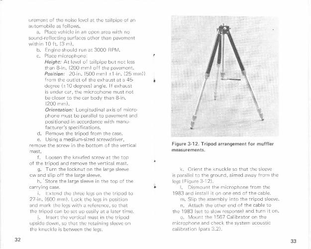
i. l::xtend the three legs on the tripod to 27-in. (600 mm). Lock the legs in position and mark the legs with a reference, so that the t ri pod can be set up easil y at a later t ime.
j. Insert the vertica l mast in the tripod upside down, so that the retaining sleeve on the knuck le is between the legs.
Figure 3-12 . Tripod arrangement for muffler measurements.
k. Orient the knuckle so that the sleeve is parallel to the ground, aimed away from the legs (Figure 3-12).
I. Dismount the microphone from the 1983 and install it on one end of the cable.
m. Slip the assembly into the tripod sleeve. n. Attach the other end of the cable to
the 1983 (set to slow response) and tu rn it on. o. Mount the 1567 Calibrator on the
microphone and check the system acoustic calibration (para 3.2).
33

34
p. Pay out enough cable so that the observer, holding the 1983, is well clear of the microphone.
q. Mount the windscreen on the 1983 and look for a muffler noise level not to exceed 95 dBA.
\0 ~ ' ' .<:"\M ICROPHO NE ~,LOCATION
Figure 3-13. Dual extended tailpipes.
/ /
I lo I I ., LESS THAI'-< ,.
Figure 3-14. Dual extended tailpipes.
r ~ 0 ~-~-
Mif~2:~~~E I L .J \ ~ .._+ ,.... \-- ~0"?- """':J
Figure 3-15. Tailpipe under vehicle or extends out at an angle of more than 45 degrees with front to back axis of vehicle. 35

36
/ /
/(!s · 10: MICROPHONE~· ~~ LOCATIO~~ 1
/ I
I I I
Figure 3.16. Tailpipe under.
~~
' / -~--·~ICROPHONE 1 \ ,o ..h_OCATION
~~" -: ~~~N \~ I A~ \
Figure 3-17. Tailpipe under vehicle or extending out at an angle of less than 45 degrees with front to back axis of vehicle.
Section 4 THEORY OF OPERATION
4.1 GENERAL
A block diagram of the sound-level meter is shown in Figure 4-1 . The names of circuits and components refer to this diagram and to the schematic diagram for the sound-level meter.
The 1983 active circuitry, two FET's (fieldeffect transistor) and six IC's (integrated circuits) , is contained on a single etched-circu it board with the exception of the microphone
Figure 4-1. Block diagram of the sound level meter.
37

28
The law also requtres that the hearing protector used by the employee reduce the notse level to within permitted limits. Thus, the noise reduction factor (R) of the hearing protector first has to be determined. The Recommendation describes some complex methods of calculating this noise reduction factor.
It can be measured d irectly using a small remote microphone assembly (P/N 1954-9640) used on the 1954 No ise Dosimeter.* The microphone fits under the hearing protector as shown in Figure 3-11. The cable coming out of the hearing protector has negligible effect on the noise reduction. This microphone assembly can be unplugged from any GR 1954 Noise Monitor or it can be obtained from the GR Service Department. The p lug on this small microphone assembly p lugs directly into the internal socket on the 1983 SLM, in p lace of the microphone on the SLM.
The procedure is as follows: a. Remove the meter and etched board
from the case, as in para 3. 1. b. Unplug the microphone plug on the
etched board. c. Dismount the m icrophone from the SLM,
unscrew the externa l connector from the case and withdraw the lead and plug.
d. Insert the plug of the 1954 Microphone Assembly through the microphone mount tube
* "A Dtrect Measurement of Datly Notse Dose for Employees Wearing Hearing Pro· tectors". Paper presented at the American Industrial Hygiene Conference, May 16, 1974, by Martin W. Basch, General Radio Company. Wrtte to General Radio Company, Concord, Mass. 01742, for copies of the paper.
Figure 3-11. Measurement of noise w ithout hearing protector attenuat ion . Protector in normal position fits easily over microphone.
and plug it into the socket on the board observing correct polarity . Reinstall the metEr in the case and calibrate the microphone using the 1954 indicator.
NOTE This calibrator in the Indicator puts out 116.5 dB, so that the CAL adjustment in the 1983 should be adjusted for a 116.5 dB reading on the meter (para 3.2).
29

38
buffer. This circuitry consists of an FET fol lower, an A-weighting network, an ampl1f1er, an rms detector*, a meter ampl if1er and a regulated power supply.
4 .2 CIRCUITRY
The ceramic microphone in the SLM, which includes a built-m FET, drives the A-weighting network, which includes C2, C3, R4 and R5. The output from this network is amplified by U2. A gain control (R11) on the amplifier is used to compensate for sensitivity variations between microphones. The a-c output from the amplifier is fed to an rms detector (U3, U4, U7) whose d-e output voltage is proportional to the log of the rms value of the input voltage.
Following the detector 1s meter amplifier U5. This stage provides isolation and the neces sary gain between the detector and the meter. R23 provides for adjustment of the slope of the detector transfer curve. R27 samples the meter current and provides a d-e output voltage proportional to the meter indication. R35 isolates the de output jack so that it may be shorted without affecting the instrument reading.
4.3 POWER SUPPLY
The power supply consists of 03, an FET, providing constant-current drive for zener diode (VR1). The voltage across (VR1) is constant for changes in battery voltage, down to the "replace battery" mark on the meter. U6 is a buffer, yielding - 3.5 V regulated and driving ground to split the battery voltage.
• U. S. Patent No. 3,681,618
Section 5
SERVICE AND MAINTENANCE
5.1 GR FIELD SERVICE. Our warranty (at the front of this manual)
attests the quality of materials and workmanship in our products. When difficulties do occur, our service engineers will assist in any way possible. If the difficulty cannot be eliminated by use of the following service instructions, please write or phone the nearest GR service facility (see back page), giving full information of the trouble and of steps taken to remedy it . Describe the Instrument by type, serial, and ID numbers.
5.2 INSTRUMENT RETURN. Before returning an instrument to General
Radio for service, please ask our nearest office for a "Returned Material" number. Use of this number in correspondence and on a tag tied to the instrument will ensure proper handling and identification. After the initial warranty period, please avoid unnecessary delay by indicating how payment will be made, i.e., send a purchase-order number or (for transportation charges) request "C.O.D."
For return shipment, please use packaging that is adequate to protect the instrument from damage, i.e., equivalent to the original packaging. Advice may be obtained from any GR office.
39

40
5.3 SERVICEABILITY TEST
The procedures outlined below can be used to determine that the 1983 is functioning pro· perly .
5.3.1 Test With Sound-Level Calibrator .
The GR Type 1562 or 1567 Sound·Level Calibrators provide a test signal for rna king a rapid check of the overall (including the micro phone) gain of the instrument. The 1562 provides a test signal at 5 frequencies, ranging from 250 Hz to 2000 Hz. The 1567 provides a test signal frequency at 1 kHz only .
Set the 1983 switch to the battery check position first, to verify that the battery is good. The meter should indicate above the battery mark .
Fit a 1/2~n. coupler-adaptor to the 1562 or 1567 Calibrator. turn the calibrator on (set at 1 kHz) and place it over the 1983 microphone . Set the 1983 to ON. A reading of 114 ± 0 .5 dB should be indicated on the 1983 meter . If it does not, adjust the CAL control (screwdriver control, accessible through the tripod mounting hole) for 114.0 dB.
The 1562 can be used to provide a quick check of the A-weighting response. The correct I evel f:Jr each frequency setting is shown in Table 5-1 .
5.3.2 Calibration check with Oscillator and Voltmeter.
An electrical test can be made on the instrument, excluding its microphone with an oscillator that covers the frequency range from 20
Table 5 -1
FREQUENCY VS dB LEVEL
1562 Freq Hz
125 250 500
1000 2000
1983 Meter Indication
97 .8 ±1 .5 dB 105 .4 ±1.5 dB 110.8 ±1 .0dB 114.0±0.5 dB 115 .2±2 .0dB
Hz to 10 kHz, and an accurate a-c voltmeter (to monitor the oscillator output voltage).
An electrical calibration check can be performed by the following procedure :
a. Remove the 1983 meter and etched board from the case (refer to para. 5.4) and disconnect the microphone lead from the con
nector on the board. b. Connect the oscillator to the input of
the 1983 using a double banana to microphone connector cable (Table 5-2) positive to AT1 and negative to AT3. Adjust the oscillator at 1 kHz for 31 .7 mV, as monitored on the voltmeter. (An attenuator such as the GR 1450-TB may be necessary to reduce the oscillator output voltage to obtain the desired level).
c . Set the 1983 to ON (slide toward microphone connector) .
d. The correct indication on the meter depends on the sensitivity of the microphone for which the instrument was adjusted . For a microphone of normal sensitivity 1- 50 dB re 1 V/N/m 2 • or - 70 dB re 1 V /11-bar), the 1983
• N / m 2 = Pa•c al (Pa ) in Sl uni ts . 41

42
should read 114 dB; this corresponds to the 31.7 mV input signal from the oscillator. Unless the actual sensitivity of the microphone is known, it is not poss1ble to calibrate the instrument prec1sely to the m1crophone using the above method. This method may be used only as an approximate check of calibration. Minimum and maximum microphone sensitivities normally used on th1s instrument range between - 53 to -47 dB re 1 V /N/m' (- 73 to -67 dB re 1 V/JJbar); therefore, the 1983 should indicate between 111 and 117 dB. For a precise calibration of the microphone to the instrument, a sound level calibrator such as the G R 1562 or 1567 should be used.
e. The A-weighting response can be checked at individual frequencies by setting the oscillator to the desired test frequency and not1ng the level of response with respect to the reference of 1 kHz. Refer to Figure 3-5 for the A-weightmg response curve.
Para. 5.5.5 (Test and Calibration) details an A-weighting response check.
5 .4 INSTRUMENT DISASSEMBLY/ASSEMBLY PROCEDURE.
CAUTION This instrument should be serviced by skilled service personnel. The procedure outlined below is intended as a guide for skilled service personnel.
5.4.1 Disassembly for Battery Replacement or Electrical Testing.
a. Place the instrument face up and loosen the two screws used to secure the meter to the case.
CAUTION Pull meter out slowly. It is attached to microphone cable.
b. Grasp the meter and lift straight up from the instrument. The meter. etched board and battery holder will all be intact when removed.
c. The microphone may be disconnected by unplugging the 3-pin connector on the microphone cable from the socket on the etched board.
d. Remove the battery from the holder, if replacement is necessary.
5.4 .2 Disassembly for Board and Meter Servicing.
a. In addition to the above disassembly, proceed as follows for a more complete disassembly.
b. Remove the battery holder itself from the meter by removing the screw securing the holder to the meter.
c. Remove screw and washer at edge above meter.
d. Remove the springs, washers and C-c lips from each meter screw; this will allow the etched board to be lifted from the back of the meter, thus allowing complete access to the board.
The microphone can be unscrewed from the case (ccw direction) and removed if necessary. The cable and connector attached to the microphone will feed through the hole in the cose.
5.4.3 Reassembly .
To reassemble the instrument, reverse the above procedures. When replacing the complete assembly into the case, make sure that the tab on the ON /OFF Switch is in position to mate with the slide button on the case. (Set the button
43

44
on the case to OFF, and center th e switch on the etched board before mating) .
NOTE The 1983 will operate while completely disassembled, providing the battery and microphone are still connected .
5 .5 1983 SLM TEST AND CALIBRATION
5.5.1 General.
The following procedures are intended for an exper ienced technician to follow in recali brating and testing the equipment . These procedures should be followed after the instru ment has been repaired or when the test of para . 5 .3 shows that the in strument may not be working according to specificat ions. The instrument should be removed from the case and the microphone disconnected before performing the following tests . Refer to para. 5.4 (Instrument Disassembly / Assembly Procedure).
A list of recommended test equipment is given in Table 5-2 .
5.5.2 Power-Supply Check .
a. Connection should be made to an external power supply to allow monitoring of the instrument current drain and low and high operating voltages. With the HP 6215 Power Supply output set to zero, connect this supply to the 1983 battery clip (observe proper polarity) . Connect a VOM (set for current, 10-mA range) in series with the positive lead for the purpose of monitoring current .
Table 5-2 TEST EQUIPMENT
Instrument Minimum Requirements Recommended*
Power Supply
Oscrllator
Counter
0-10 V, 20 mA
2 Hz 20 ~Hz 0 20 V Open Ckt
Frequency '25Hz 10kHz) Interval (200 500 ms)
HP 6215
GR 1310
GR 1191
Oe<:adeAnenuawr 0 1-dB.l<IB,lO·dBs teps GR1450TB
AC -DC Voltmeter Runge 0-10 V 2% accuracy 2540 DVM
(Data Precrsronl
Drstmtron Analyze, 100Hz 20kHz HP 334A
300 JJV 1 V rms full scale
Sound Le~l Calibrator 1/2 H,_ acoustrc cLupler GA 1562 or
1567
Patch Cord 131 Double banana-plug (27 41 to GA 274 NP Double banana-plug
Patch Cord ( 11 BNC to BNC G R 776 c
Adaptor (1) Banana-plug pan 10 GR 874 GR 874-010
Adaptor (21 BNC 1ack 10 GR 874® GR 874 OBJA
Adaptor Cable Double banana-plug !2741to GR 1060 P77 mtn•ature phone plug
Adaptor Cable Double banana-plug to ci•P leads Make up
Remttve Load 600 H · 5% GR 500-G
Tone -Burst Generator 200-500 ms pulses, contmuous GA 1396-B
Aoaptor Cable Double banana plug (2741 to Make up m•crophone connector t
Decade Remtor 15 kH GR 1433-L
Res•stor 600 n 600 H, 1/4 W
Patch Cord !21 GR 274-LLR
Osc•tloscope
Probe
S•ngle banana-plugs
General Purpose
Xl
Tektron•x 503
Tek tron• x P60 11
Pulse Generator
" Or equo.,alr>nl
200 jJS pulses, 500 Hl POSIIIVC
negative GR1340
IPic~stoc Prod\, Inc typf> 162 plug 13 p1nl
45
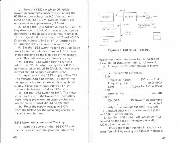
b. Turn the 1983 switch to ON (slide toward microphone connector) and adjust the 6215A output vol tage for 9.0 V de, as moni tored on the 2540 DVM. Nominal supply current should be approximately 3 .2 mA.
c. Check the 1983 supply voltage VB- at TP9 (negative side of C14) . Voltmeter ground can be connected to the de output jack mount bracket . This voltage should be between -3.3 and -3.6 V. Check the voltage VB+S at TP1 0 (positive side of C13); should be between 5.4 and 5.7 V.
d. Set the 1983 switch to BAT position (slide away from microphone connector). The meter should indicate on the high side of the battery mark. This indicates a good battery voltage .
e. Set the 1983 switch back to ON and adjust the 6215A output voltage for 7 .0 V de, as monitored on the 2540 DVM . Nominal supply current should be approximately 3 mA.
f . Again check the 1983 sup pi y VB-at TP9 . This voltage should be within - 10 mV of the voltage noted in step c., since it is a regulated supply. Check the voltage VB+S at TP10; it should be between +3.4 and +3.7 Vdc.
g. Set the 1983 switch to BAT. The meter should indicate on the low side of the battery mark ; this is the minimum battery voltage at which the instrument should be operated .
h . Reset the supply voltage to 9 .0 V from the 6215A for the remaining checks , or install a good battery .
5.5.3 Meter Adjustment and Tracking
a. With the power on the 1983 OFF and the meter in a horizontal position, adjust the
46
Figure 5·1 Test setup - general.
mechanical meter zero screw for an indication of exactly 70 (adjustment on rear of meter).
b . Arrange the test setup shown in Figure
5-1. c. Set the controls as follows: 1310
.200Hz - 2kHz 10 (1 kHz)
. Adjust for 1 Von DVM
Frequency Range Frequency Dial Level .
1450 Attenuation
1983 ON / OFF .
. 74 .0 dB
ON (toward microphone . connector}
d. Adjust the microphone sensitivity pot (R11, located adjacent to the d-e output jack) for 70 .0 dB on the meter.
e. Set the 1450 to 24 .0 dB and adjust R23 (located on the edge of the etched board) , for 120 .0 dB on the meter.
f . Check the meter tracking in accordance with Table 5-3 by setting the 1450 as indicated.
47

48
Table 5-3
METER TRACKING
Set 1450
24 .0 dB 29 .0 dB 34.0 dB 44.0 dB 54 .0 dB 64 .0 dB 74.0 dB
Meter Reading (dB)
120.0 (set using R23) 115.0±0.35dB 110.0±0.5 dB 100.0±0.7 dB
90.0±0 .7 dB 80.0±0.7 dB 70.0 (set using R 11)
5.5.4 AC level and Distortion Check
a. Retain the same setup of Figure 5-1 and set the controls as follows:
1310 Frequency Range Frequency Dial Level .
1450
. 200Hz - 2kHz 10 (1 kHz)
Adjust for 1 Von DVM
Attenuation 24.0 dB 1983
ON/OFF . ON b. Usi11.g a 274 (double) to clip-lead cable,
connect the 334-A (set to VOLTMETER, 1 V RANGE) to TP13 on the 1983 (junction of C7 and R14).
c . The a-{; voltage at TP13, as indicated on the 334-A, should be approximately 0.5 V.
d . Set the 1450 to 13 dB (overdrive 1983 by allowable crest factor) .
e. Set both the FUNCTION and METER RANGE on the 334-A to SET LEVEL. Adjust the SENSITIVITY for full-scale and measure the distortion to be less than 1%.
5.5.5 A-Weighting Check
a. Retain the same setup of Figure 5-1 and set the controls as indicated in para 5 .5.4 step a.
b. Check the A-weighting response in accordance with Table 5-4 by setting the 1310 frequency as indicated and adjusting the 1450 for a meter reading o¥ 70 .0 dB in each case. The setting on the 1450 should fall between the I i mits as shown in the table.
Table 5-4
A-WEIGHTING LIMITS
Set 1310 Frequency
1 kHz
500Hz 100Hz 25Hz 8kHz
1450 limits
(Reference, set for 70.0 on meter)
69.8 - 71 .8 dB 53.9 - 55 .9 dB 29.3 - 32 .3 dB 71 .4 - 74.4 dB
5 .5 .6 DC Output Check .
a. Retain the same setup of Figure 5-1 and set the controls as indicated in paragraph 5 .5.4 a.
b. Connect the 2540 DVM to the de output on the 1983 using a 1560-P77 patch cord.
c. The de output as indicated on the 2540 DVM should read 250 ± 10 mV .
d . Adjust the 1450 slightly such that the de output reads exactly 250 .0 mV. e. Increase the input to the 1983 (1 0 dB
above full-scale) by decreasing the attenuation from the 1450 by 10 dB (1450 10 dB/STEP set to 1). The do{; output should indicate 300 ± 5mV.
49

50
f. Decrease the input to the 1983 (bottom· scale) by increasing the attenuation from the 1450 (1450 10 dB/STEP set to 7). The d-e output should indicate 0 ± 1 mV . Any variation from the above tolerance would tend to indi cate improper adjustment of the meter as detailed in para. 5.5.3 , or improper adjustment of the mechanical zero.
5 .5 .7 Meter Ballistics Test
a. Arrange the test setup shown in Figure 5-2.
NOTE Connect a 600-D resistor in ser ies with the high side of the 1396 SIGNAL OUTPUT to effectively increase the low output impedance . Connect a Decade Resistor (G R 1433-U between the high side of the 1396 SIGNAL INPUT and the high side of the SIGNAL OUTPUT (connect to attenuator side of the 600-D resisto r ).
b . Set the control s as follows :
1310 Frequency Range Frequency Dial Level
1450 Attenuation
1396 Trigger Level . Slope . Cycle Count . Timing (rear) . Output ON Output OFF .
. 200 Hz - 2 kH z 10 (1 kHz )
. Adjust for 1 Von 2540
10 .0 dB
0 (- )
NORMAL INT
.CONT
. 1 Sec
Figure 5-2. T est set-up for meter ball ist ics check .
1191 Interval Range . D1splay T1me. (Input A) AC/ DC (Input A) Polarity & Atten. (Input B) AC/DC (Input B) Polarity & Atten .. Separate/Common
1983 ON/OFF .
Depressed .10 IJS
100 mS DC
. 1 (+)
DC .1 (- )
COMMON
ON
Connect the jumper wire on the 1983 to F (fast meter response).
c. The lamp behind CONTon the 1396 OUTPUT ON dial should now be on.
d. Adjust the 1450 attenuator for a reading on the 1983 meter of 116.0 dB.
e. Set the 1396 OUTPUT ON for approximately 0.2 SEC and adjust this dial for a read-
51

ing of 200 on the 1191. (This sets the time inter val of the pulse for 0.2 sec.)
f. Set the 1396 OUTPUT OFF for 10 SEC and adjust the 1433 Decade Resistor for a meter reading of 96 .0 dB on the 1983 when the tone burst is off (1433 set for approximately 5 k!1) . This will set the output tone burst from the 1396 for steps of 20 dB amplitude .
g. Dur ing the on time of the 200 ms bursts, the meter reading should go to 114 .0 • 2.0 d B
h. Set the OUTPUT OFF 'to 1 SEC and connect the jumper wire on the 1983 to S (slow meter response).
i . Adjust the OUTPUT ON dial for a reading of 500 on the 1191 . (This sets the time interval of the pulse for 0.5 sec.).
j . Reset the OUTPUT OFF for 10 SEC. During the on time of 500 ms bursts , the meter reading should go to 112.0 ± 2 dB.
52
5 .5.8 Noise Level Check
a. Disconnect the 1983 from the test setup and reconnect the microphone to the etched board (microphone should be installed on case).
b. Connect the 2540 DVM to the 1983 d-e output, using a 1560-P77 adaptor cable.
c. Place a 1 562 or 1567 and 1 /2-in . coupler adaptor over the microphone (calibrator
turned 0 F F) . The 1983 should be 5 dB or more below bottom scale or greater than - 25 mV on the 2540 DVM .
5.5.9. Detector Balance Check
a. Arrange the test setup shown in Figure 5-3, connect to position 1 (+PULSE) on the
1340.
b . Set the controls as follows:
1340 Pulse Period/Frequency Pulse Duration . . Pulse Offset (large knob) Pulse Offset (small knob)
1450 Attenuation
1983
3.0 x 1 ms . 2 .0 X 100 1JS
0 . 0
40.0 dB
ON/OFF . ON
c. Adjust the+ pulse amplitude for a 5-V pulse on the scope, using the small knob of the PULSE AMPLITUDE control of the 1340.
d . Adjust the 1450 attenuator such that the 1983 meter indicates 119 dB.
e. Move the 1450 connection to position 2 of Figure 5-3 (- PULSE output of the 1340) . Adjust the - pulse amplitude for a 5 V pulse on the scope, using the large knob of the PULSE AMPLITUDE control.
Figure 5-3. Test set-up for detector balance check.
53

54
f. The reading on the 1983 meter should be within 1 dB of the previous read mg.
g. Adjust the 1450 such that the 1983 meter indicates 71 dB.
h. Move the 1450 connection to pos1t1on 1 of Figure 5-3(+ PULSE output of the 1340). The reading on the 1983 meter should be within 1 dB of the reading noted in the prev1ous step.
5.5.1 0 Final Calibration
a. Final calibration of the microphone to the instrument should be performed using a Type 1562 or 1567 Sound Level Calibrator.
b. With the microphone installed on the mstrument, fit a 1'2-i n . coupler-adaptor to the 1562 or 1567, turn it on (set at 1 kHz) and place it over the 1983 microphone.
c. Set the 1983 to ON . If the meter does not read 114 ± 0.5 dB, adjust the CAL control (screwdriver control, accessible through the tripod mounting hole) for 114.0 dB.
5.5.11 Meter Window Care.
The clear acrylic meter window can be
come susceptible to electrostatic-charge build
up and can be scratched, if improperly
cleaned. It is treated inside and out in manufactur
ing with a special non-abrasive anti-static solution, Statnul*. which normally should preclude any interference in meter operation caused by electrostatic effects. The problem is evi-
• Available from Mancib Co., Burlington, MA 01803 .
denced by the inability of the meter movement to return promptly to a zero reading, once it is deenergized. As supplied by General Radio, the meter should return to zero reading within 30 seconds. immediately following the plac~ment of a static charge, as by rubbing the outside surface. This meets the requirements of ANSI standard C39.1-1972.
If static-charge problems occur, possibly
as the result of frequent cleaning, the window should be carefully polished with a soft dry
cloth, such as cheesecloth or nylon chiffon. Then. a coat ing of Statnul should be applied
with the polishing cloth.
CAUTION Do not use any kind of solvent. Kleenex or paper towels can scratch the window surface.
If it should be necessary to place limit marks on the meter window, paper-based mask
ing tape is recommended, rather than any kind of marking pen. which could be abrasive or react chemically with the acrylic.
5.6 TROUBLE ANALYSIS
5.6.1 General.
If it is desired to repair a defective instrument, waveforms and voltages are shown on the schematic (for a predetermined input signal). These waveforms will help isolate the problem to a part or parts on the board.
55

SWITCH KNOB ASSEMBLY
SEE FIGURE 56 FOR DETAILS
BATTERY CUP
METER FAST/SLOW JUMPER
BATTERY LINEARITY SLEEVE ADJUST
IR231
Figure 5-4. Interior view of the SLM.
MECHANICAL PARTS LIST
Ouctiplion
Case, molded, asm Slide Button includes:
spring spring
Microphone asm Meter assembly Dust cap Snap button 0.359-in. Snap button 0.219-in.
1983-110 1 1983-7100 1983-8040 1983-8010 1983-2200 5730-1450 1972-7410 4160-0250 4160-0270
MISCELLANEOUS
56
Battery 2U6 Battery strap Switch asm, S-1 (located on 19834700 Board) includes:
Cover Carrier Co ntacts
84 1().3200 8160-{1120
1983-8000 1983-7020 1983-8030
2
,-- 5
I .-6 \
7
Figure 5-5. Replaceable mechanical parts. 57

58
ELECTRICAL PARTS LIST
... "" ~tption Fod
GR Part No. Mfg Code Mfg P.-t No.
CAPACITORS
Cl Cap, Tant, 6.8 ~-tf, ±20%, 6V C2 and
4450-4800
CJ Cap, Mylar, .00487 .uF, ±2%, 100 V 4860.7404 C4 Cap. Mica , 665 pf, ±5%, 300 V 4710.0645 C7 Cap, Tant, 1.0 uF ±5% 20 V 445()-4302 CB Cap, Cer, 150 pF ±5% I 00 V 4400-6491 C9 Cap. Cer. 47 pF, ±5%, 100 V 4400-6487 CIO Ca_p. Cer. 0.68 pf ±5% 500 V 440~069
Cl I Cap, Tant, 6.8 uF ±10% 15 V 4450-6405 Cl2 Cap, Tant, 1.0 uF ±10% 35 V 4450-4301 Ci3 and Cl4 Cap, Tant , 33 uF ±20% 10 V Ci6 Cap, Cer, .0 1 uF +80-20% 100 V Cl7 Cap.Tant.,0.47~JF± I0%,3S V CIS Cap,Cer, 270 pF ±5% 100 V
CONNECTOR
J I Miniature, Jack, Shield
DIODES
VRI Zenr· IN75l,±l%
INTEGRATED CIRCUITS
U2 Type MC3476G UJ Type CA3130T U4 Type MC3476G US and U6 TypejJ.A776
METER
ME-l
RES ISTORS
R2 Comp., 18 kilohms ±tO% 1/8 W R3 Comp., 1.8 kilohms ±10% 1/8 W R4 and KS him, I 15 k.ilohms ±I~ 1/8 W RIO Film, 2.37 kilohms ±I% 1/8 W RJ I Pot. Cermet, 5 kilohms ±20~ R 12 Film, 31.6 kilohms ± I% 1/8 W R 13 Comp., 220 kilohms ±5% l /8 W R 14 Film, 6.04 kilohms ± I% 1/8 W Rl5 Film,l4.7 kilohms+0.5 % 1/8 W Rl6 Film, 29.4 kilohms ±0.5% 1/8 W R 17 Comp., 330 kilohms :t I 0% 1/8 W R 18 Comp., 47 kilohms ±I 0% 1/8 W R20 Film, 15.4 megohms ±I% 1/ 4 W R21 Film, 10 kilohms ± I% 1/8 W
4450-5400 4401-3100 4450-6430 4400-6494
4260-1110
6083-1102
1983-{)470 5432-7000 1983-o470
5432-1039
5730-1450
6098-3189 6098-2189
6250-3115 6250-1237 6049-{)420 6250-2316 6098-4225 6250-1604 6251-2147 6251·2294 6098-4339 6098-3479 6350-5154 6250-2100
56289 150D685XOOIOA2
84411 663UW, .00487 uF 81349 CMOS, 665 pF ±5% 12954 D Series, 1.0 uF ±5% 72982 8101, 150pF±5% 72982 8101,47 pF ±5% 95121 QC,0.68 pF .!.5% 56289 1620 ,6.8 uF ±10% 56289 150DI05X9035A2
56289 150D336XOOIOBI 72982 805, .01 uF +80-20% 56289 1620,0.47 J1F ±10%, 35 V 72982 8101,270pF±S%
82389 TR2A
12498 1N751
24655 1983-()470 79089 CA3130T 24655 1983-0470
24655 5432-1039
24655 5730-1450
01121 RCR05G183K 01121 RCR05GI82K
75042 CEA, 115 kilohms 75042 CEA, 2.37 kilohms 80294 3339, 5 kilohms ±20% 75042 CEA, 31.6 kilohms 01121 RCROSG224J 75042 CEA, 6.04 kilohms 75042 CEA, 14.7 kilohms 75042 CEA, 29.4 kilohms 01121 RCR05G334K 01121 RC'R05G473K 75042 CEA, 15.4 megohms 75042 CEA, 10 kilohms
ELECTRICAL PARTS LIST CC..ti
R22 Film, 45.3 kilohms ±I% 1/8 W R23 Pot. Ceramic, 10 kilohms ±20% R24 Comp., 1.8 megohms±IO% 1/8 W R25 Comp., 220 kilohms ±10% 1/8 W R26 Film, 4 .32 kilohms ±I% 1/8 W R27 Film, 249 ohms t I% I /8 W R30 Co mp., 33 kilohms ±5% 1/4 W R31 Comp .• 75 kilohms ±5% 1/4 W R32 Comp., 330 kilohms ±10% 1/8 W R33 Comp., 27 megohms ±5% 1/4 W R35 Film, 100 kilohms ±I % 1{8 W R36 Comp., I megohm ±10% 1/8 W R37 Comp .• 390 kilohms ±10% 1/8 W
SOCKET
SO-l Socket
TRANSISTORS
QJ Type E501 Q4 Type 2N4339
GR PwtNo.
6250-2453 6049-0317 6098-5189 6098-4229 6250-1432 6250-0249 6099-3335 6099-3755 6098-4339 6099-6275 6250-3100 6098-5109 6098-4399
4230-8700
8215-0100
Fod Mft c~ Mtt ~.n No.
75042 CEA, 45.3 kilohms 80294 33845, 10 kilohms 01121 RCR05GI85K 01121 RCR05G224K 75042 CEA, 4.32 kilohms 75042 CEA, 249 ohms 01121 RCR07G333J 01121 RCR07G753l 01121 RCR05G334K 01121 RCR07G276l 75042 CEA, 100 kilohms 01121 RCR05GI05K 01121 RCR05G394K
24655 4230-8700
!E
Fig

I ·~·~~ ~ , .:~-~ I - ~ •.•
1-f~·i~~ f---IL'. ~! ht ~ I l1i 1 1 :1 , I __ :._) I
- ~·.:. ~;--::~ J. I ~· ..... v
- tt.4
::~~ ... I
I I
I I
I
I I I
I I I L
L - uit board diagram. Etched ClrC Figure 5·6 .
Q3
I I I
J
AI1Pllflff!
POWER 5UPI'I.Y
-- . ram for 5 7 Schematic dlag Figure · ·
• oar A.f '.lov fll.c.E
~~O'~CE 0 OP. ... IN
03
1983 SLM.
I I
4 JZ .< ~" I
/)t!oGJl ... M\ ( 8 0 T10"" Vlf W I)
~0'~~·- :~, ~ 2 -,/a
&ATE V l · 7
Qq. ]NT£61U!Tf 0
CIIKINFJ
59

FEDERAL MANUFACTURER'S CODE
From Federal Supply Code for Manufacturers Cataloging
Handbooks H4-1 (Name to Code) and H4-2 (Code to
Name) as supplemented through August , 1968.
01121 07263
09823 12040
12498 12954
17856 24655
56289
72982
75042
80294
82389 84411 95121
Allen Bradley Co., Milwaukee, WI 53204 Fairchild Semiconductor. Mountain View, CA 94040 Burgess Battery Co., Freeport, IL 61032 National Semiconductor. Santa Clara, CA 95051 Teledyne, Inc .. Cambridge, MA 02140 Dickson Electronics Corp., Scottsdale, AZ 85252 Siliconix, Inc ., Sunnyval e, CA 94086 General Radio Co ., 1 •
West Concord, MA 01 742 Sprague Electric Co .. North Adams, MA 0124 7 Erie Technological Products, Erie, PA 16512 IRC - Div. of TRW, Burlington, /A 52601 Bourns Laboratorr es Inc. , Riverside, CA 92506 Swithcraft Inc., Chicago , I L 60630 TRW Capacitor, Ogallala, NB 69153 Quality Components Inc., St. Marys, PA 15857