gpu service corporation
TRANSCRIPT

_.
,a- n: . :. ...-.~.w.-.~..- . . . . . . . . . -- ,..-
_
- ,c
13587-2-G03-105-. , - -,.,
,
. . , . . 4.
.,
W,
i
s + - '
*1; .
TECHNICAL EVALUATION REPORT
FOR
,-
INTERIM SOLID WASTE STAGING FACILITY
FOR
GPU SERVICE CORPORATION
THREE MILE ISLAND - UNIT 2
.
,
L
|
-
Bechtel Northern Corporation.-
Bechtel Job 13587,
.
Revision 3.
May 1981
3810ea3034
- . - .- . . . - - - -

.
__
.'.,
LATEST
LATEST | SHEETLATEST LATEST LATEST LATEST LATEST
.
SHEET REV. SWEET REV. R EV. SHEET REV. SHEET REV. SHEET REV. SHEET R E V.
1 0|
11 0-
1-1 0
1-2 0.
2-1 0 -
2-2 3
2-3 3
2-4 0
2.: 0
Fggi O
h!i 0
3-1 0
3-2 0
3-3 2
3-4 3 g"3-5 2
3-6 2
3-7 2
3-8 2
$bk" 0
4-1 0
IIf* n
5-1 0
|
1
I
.-.
hnus
1 'E -
REVISION STATUS SHEET JOB / GROUP 13587 REV.j kg[[)J- Technical Evaluation Report for DISCIPLINE
|R Jj Interim Solid Waste Staging Facility uclear 3DOCUMENT TITLE:PAGE 1 OF 1
- __

-
. _ _ . _ . _ . _ , _ . . - - - -
L .
~'
-
13587-2-G03-105*.
TABLE OF CONTENTS
Pagg
1.0 INTRODUCTION 1-1*.
1.1 General 1-1- 1. 2 Organization of_ Report 1-11.3 Conclusion 1-1
2.0 FACILITY DESCRIPTION 2-1
2.1 Purpose of the Facility 2-12.2 Summary _ Description 2-1
2.2.1 Location 2-12.2.2 Design Basis 2-1; 2.2.3 Building Description 2-1
2.2.4 General Arrangement 2-2
2.3 Major Systems 2-32.4 Material Handling Operations 2-3
2.*.1 Description of Pack, ages 2-32.4.2 _ Unloading and Stacking of the Packages 2-42.4.3 Removal of Pcckages 2-4
Table 2-1 Design Storage RequirementsFigure 2-1 Recovery Facilities PlanFigure 2-2 ISWSF General Arrangement
3.0 TECHNICAL EVALUATION 3-1
3.1 Licensing Issues 3-13.2 Dose Assessment 3-1
3.2.1 Off Site 3-1,
3.2.2 On Site1 3-5
3.3 occupational Exposures 3-5
3.3.1 Design Features 3-63.3.2 Man-Rem Estimate 3-6
Table 3-1 Area Radiat,,n Levels with Six MonthsDesign Basis Inventory
-,.
.
4.0 COMPARISON WITH PROGRAMMATIC ENVIRONMENTAL 4-1IMPACT STATEMENT (PEIS)
Table 4-1 Contents of Staging Facility
i Rev. 0
. ... - _-

-. -
-
. . . . . . .. -
~"
,. 13587-2-G03-105.
5.0 SAFETY EVALUATION 5-1
5.1 Technical Specifications, 5-15.2 Unreviewed Safety Questior 5-1
,
*.
,
.
4
9
ii Rev. O
__ . _ . - -

_q. - --
u
*(* 13587-2-G03-105
,
1.0 INTRODUCTION
1.1 Generalf
The cleanup effort at Three Mile Island Unit 2 is expectedto result in the generation of a significant quantity of low level(Note 1) solid. or solidified radioactive waste. In addition, low levelsolid or solidffied radioactive waste is also being generated in Unit 1.Due to limitations on low level radioactive waste disposal sites andlimited onsite staging capacity, an additional facility for the collec-tion and temporary staging of low level solid or solidified, radioactive ' ''
waste is needed.
The facility oroposed to fulfill the need identifiedabove is the Interim Solid Waste Staging Facility (ISWSF).
This Technical Evaluation Report (TER) demonstrates thatthe ISWSF has been designed and will be operated in such a manner as toprovide assurance that: '
The health and safety of the public will be protected.a.
b. Occupational exposures will be as low as reasonablyachievable (ALARA),
There will be no adverse impact on the environment.c.
1.2 Organization of Report
This report is organized in the format of a combined- safety analysis and environmental report. Following this introduction,a description of the design and operational considerations is presented.This.is followed by a discussion of the safety and environmental issuesassociated with the facility. A comparison of the ISWSF design with the<
Programmatic Environmental Impact Statement is presented next. The reportconcludes with the safety evaluation required by 10 CFR 50, paragraph 50.59," Changes, Tests, and Experiments."
1.3 Conclusion
The information provided in this report results in the- following conclusions:.
The ISWSF fulfills the need for a facility in whicha.to temporarily stage low level solid or solidifiedradioactive waste.
.-.
Note 1. As used herein the term " low level" refers to the dose rate oncontact with the waste packages as defined in Table 2-1. Theterm gives no indication as to the isotopic or elemental contentof the package,
r 1-1 Rev. O
!-w.- . . .. + - . . .

-
~
13587-2-G03-105-.
.
b. The operation of the facility is not an unreviewedsafety question as defined in 10 CFR Part 50, para-graph 50.59.
.
' ' .
.-,
|
|
1-2 Rev. Oi
!j

,7:-
- -
O . Lj4 _1
, . . , ,.
<
1*SS7-2-G03-305
:u
2.0 . FACILITY DESCRIPTION- - |;
:2.1 ' Purpose of the Facility i
,;.. The ISWSF is to be used for 'the staging of low level
e-
solid or solidified' radioactive waste packages from both Units 1 and 2prior to shipment offsite for . disposal. The packages will be staged in
,
'the . facility for up to 2 years.
12 . 2 Summary Description
12.2.1 Location
"j. - As shown on Figure '2-1, the ISWSF is located east of the
Unit 2 turbine building and between the offsite transmission lines forUnit.2. It'is surrounded by an outer fence which aids in restrictingaccess to the area immediately surrounding the facility. Access to thearea enclosed oy the outer fence will be controlled by established plantprocedures. .The only activities occurring within this area will be- .,
those associated with the ISWSF.
2.2.2 Design Basis
The ISWSF has no safety design basis.
The facility is designed to provide a controlled but ready.access for material handling optrations to ensure that operator exposuresare as low as is reasonably achievable (ALARA). The facility is sized toaccommodate the wastes generated in 6 months from Units 1 and 2. Themonthly waste generation rates used in the design are given in Table 2-1.
In addition, the ISWSF is designed to maintain the doserate at the outer fence surrounding the facility at 0.6 mrem /hr, inaccordance with.10 CFR Part' 20, paragraphs 20.105(b)(2) and 20.202(a)(1).The facility is also designed to meet the requirements of 40 CFR Part 190-
*
at the site boundary and beyond.
2.2.3 Building Description
The ISWSF, shcwn in Figure 2-2, is a non-seismic Category I,concrete floor slab, covered by a prefabricated metal roof. Shieldingpartitions of grout-filled concrete masonry units are used to satisfythe dose. rate criteria specified in Section 2.2.2. A roof is providedto minimize the volume of rainwater entering the facility which couldpotentially become contaminated and thus require monitoring and process-'ing. The roof also allows unloading and loading of trucks during adverseweather conditions.
,
-
An 8-inch-high curb is provided around the perimeter ofthe floor slab to contain any rainwater that may enter the building.Ramps are provided to allow passage of a forklift over the curb. Thefloor slab is sloped so that any water entering the facility will bedirected toward one of the six sumps provided. With the use of portablepumps, water collected in these sumps will be disposed of in accordance
'
2-1 Rev. 0
.. .

1-
.- - . . . . _ .
.
*
.. 13587-2-G03-1059
with established plant operation procedures.' The sumps are providedwith manually actuated seaters to facilitate disposal of collected water
13during the winter..
The floor slab, sumps, and curb are epoxy coated forease of decontamination should the need arise. The exposed structuralsteel columng. in the storage areas are also epoxy coated to a height of8 inches for" compatibility with the curt'. The remaining portions of _ thesteel columns and the roof framing have a protective finish. The shield-ing partition surfaces facing the storage areas are epoxy coated to aheight of 8 inches and painted with a sealer above 8 inches. The outside,
surfaces of the partitions are painted with a sealer.
In addition to the outer fence surrounding the areaaround the ISWSF, there is an 3-foot-high inner fence provided aroundthe u2 walled sections of the facility (see Figure 2-2).
With the exception of small quantities of electricalcable associated with electrical power and the in-plant paging system,all materials used in the construction of the facility are noncombustible.2.2.4 General Arrangement
The ISWSF consists of six basic areas: (1) loading /*
unloading, (2) survey, (3) open staging, (4) Unit 1 shielded staging,(5) Unit 2 shielded staging, and (6) personnel monitoring / analysis. Adiscussion of these areas follows. The general arrangement of thefacility is shown in Figure 2-2.
2.2.4.1 Loading / Unloading Area
The loading / unloading area consists of a truck bay, aramp into the facility, and an area for the loading and unloading of astandard flatbed trailer or enclosed van by a standard forklift.2.2.4.2 Survey Area
A survey area is provided to allow for radiation surveysof the waste packages prior to placing them on a truck for shipment offsite. This area.is separated from the truck bay and the open stagingarea by shield parcitions.
2.2.4.3 Open Staging Area
The open stag, sg area is separated from the survey areaby a shield partition. For administrative purposes, it is divided intoa section for Unit I wastes and a section for Unit 2 wastes. Tae Unit 1and Unit 2. areas are flexible and shown in Figure 2-2 for illustration.These areas may vary throughout the life of the facility. These sections .
are separated by a portable barrier consisting of stanchions ccanectedby a chain. Access routes, or aisles, with gates at the entrance, allowfor the movement of the containers by a forklift to the appropriatearea.
2-2 Rev. 3,
-- -
, . _ . _ _ , __
,
i13587-2-G03-105-
.
.
It should be noted that the segregation of wastes byunit is not required by federal regulations. Rather, it is solely forutility administrative purposes.
.
2.2.4.4 Shielded Staging Areas
~ Shielded staging areas are provided in order to meet thedose rate lisiits specified in the_ design basis, Section 2.2.2. Separateshielded areas are provided in order to maintain separation between.
wastes from each unit. Access to these areas is by means of the aislesidentified'in Section 2.2.4.3. Access will be controlled by administra-tive procedures.
2.2.4.5 Personnel Monitoring / Analysis Area
The personnel monitoring / analysis area is a small cubicleat the end of the loading / unloading area. This area contains equipmentfor personnel monitoring and for the analysis of swipe samples of thewaste packages.
2.3 Major Systems
The only systems provided for the operation of the ISWSFare electrical power for lighting, receptacles, sump heaters, and the |3in plant paging system. None of these systems serve any safety-relatedfunction.
No radiation monitors are provided in the facility.This is because the facility is a radiological controlled area andaccess is controlled at the ooter fence.2.4 Materia *4 Handling Operations
2.4.1 Description of Packages
The packages to be staged in the ISWSF are of severaltypes. These are described below.
Four 55-gallon drums of compacted trash and/or solidi-fied radiac waste will be placed on 4-foot by 4-foot pallets. Dependingon the weight of each drum, they may be banded together.
A single 50-cubic-foot liner of solidified evaporatorbottoms will be placed on a 4-foot by 4-foot pallet. The dimensions ofthe liner are 4 feet in diameter and 4 feet high.
There will also be metal LSA boxes containing compactedtrash satisfying the requirements of 10 CFR Part 71. The dimensions ofthe LSA boxes are 4 feet x 4 feet x 7 feet. These boxes will arrive at
,
the facility with a spacer between each box to allow a forklift toreadily lift the box.
2-3 Rev. 3

, _ _ _ _ __ _ _ _ _ _ _ _
.-. .,
'
,
.., 13587-2-G03-105,
All waste packages received in the ISWSF will be com-| pletely prepared for shipment. All counting, swiping, decontamination,'
and weighing will be done prior to the transfer of the packages to theISWSF. Provisionc have been included in the design of the ICWSF to allowadditional counting and swiping in the ISWSF.
2.4.2 y Unloading and Stacking of the Packages
The packages of wasta. will arrive at the ISWSF on eithera standard flatbed trailer or in an enclosed van. Upon arriving at thefacility, the vehicle centaining the waste will be parked in the truckbay located in the loading / unloading area. At this point a 3,000 poundto 5,000 pound capacity forklift will unload the packages and transportthem to the proper area of the facility.
Upon arriving at the proper location within the facility,the packages will be stacked. The pallets and boxes will be stacked nomore than three high, which is consistent with current GPUSC practice.In general, the pallets will be stacked in a staggered manner. The LSAboxes will be stacked one on another with spacers.
The required lif t height of approximately 10 feet iswell within the 16-foot lif ting height of the forklif t. The capabilityof the pallets to carry the load has been checked for the design basisarrangement and has been found .cceptable. The pallets are of fourstringer design, with solid planking tog and bottom.
2.4.3 Removal of Packages
When a package is removed for shipment, the reverse ofthe procedure described in the previous section will be followed.
.
r
.-
>
2-4 Rev. 0
-__ ._. _ .

4-
13587-2-G03-105.
.
TABLE 2-1
DESIGN STORAGE REQUIREMENTS.
Quantity. Container /,
Unit (pe r 'honth) Trash Type Radiation Level
1 37 55 gal drum / compacted trash up to 50 mrem /hr
1 19 55 gal drum / compacted trash 50 to 100 mrem /hr1 15 55 gal drum / compacted trash 100 to 200 mrem /hr1 4 55 gal drum / compacted trash 200 - 400 mrem /hr
~
1 1 4'x4'x7' box / compacted trash up to 200 mrem /hr
"1 10 50 ft3 liners / solidifiedevaporator bottoms 200 - 500 mrem /hr
2 9 55 gal drum / solidifiedradiac waste up to 100 mrem /hr
2 16 55 gal drum / compacted trash 0 to 1 mrem /hr.
2 6 55 gal drum / compacted trash I to 2 mrem /hr2 11 55 gal drum / compacted trash 2 to 5 mrem /br2 9 55 gal drum / compacted trash 5 - 20 mrem /hr2 5 55 gal drum / compacted trash 20 - 100 mrem /hr2 2 55 gal drum / compacted t rash 100 - 500 mrem /hr2 1 55 gal drum / compacted trash 500 - 1000 mrem /hr2 1 55 gal drum / compacted trash 1000 - 2000 mrem /hr2 2 4'x4'x7' LSA boxes 0 - 1 mrem /ht2 2 4'x4'x7' LSA boxes 1 - 2 mrem /hr2 3 4'x4'x7' LSA boxes 2 - 10 mrem /hr
.-
2 3 4'x4'x7' LSA boxes 10 - 20 mrem /hr.
2 3 4'x4'x7' LSA boxes 20 - 100 mcem/hr2 1 4' x4 'x7' LSA boxes 100 - 200 mrem /hr
4
Rev. 0|
,- . .- . -

.
n-, . , ~ . - . - - - - - -,
-, _
.13587-2-G03-105
.
3.0 TECHNICAL EVALUATION
This,section summarizes the licensing issues which wereconsidered in the' design of the ISWSF. These issues deal With theexpected performance of the facility during normal operation and variousdesign basis events.
'5( Licensing Issues3.1 '
The licensing issues associated with the operation ofthe ISWSF are:
a. Demonstrating compliance with 40 CFR Part 190 withrespect to offsite doses.
b. Demonstrating compliance with 10 CFR Part 20 withrespect to onsite dose limits.
Demonstrating that the design basis events for thec.
facility have been properly considered. The designbasis events for this facility are high winds, OBE,fire, and flooding.
d. Demonstrating compliance with the principles ofALARA.
Each of these issues is addressed in the followingsections.
3.2 Dose Assessment
The ISWSF is designed so that during normal operation(1) the requirements of 40 CFR Part 190 are met at the site boundary andbeyond, and (2) the done rate at the outer fence is limited to 0.6 mrem /hror less. In addition, the consequences of desiga basis events have beenevaluated to assuceb that public use of areas beyond the exclusion areasis not interrupted or restricted.
This section presents the analyses that demonstrate the, , .
above objectives are met.
3.2.1 Off Site
3.2.1.1 Normal Operation
The total annual offsite dose from the site to anyindividual is limited to 25 mrem by 40 CFR Part 190. The nearest siteboundary fo.r. the ISWSF is the normal high water mark on the east bank ofthe island. ,
.
3-1 Rev. 0
'
,

i
- -
13587-2-G03-105
As applied to the site boundary, the 40 CFR Part 190limits equate to a 0.3 mrem /hr dose rate based on a 67 hr/yr occupancy(Note 2) with an 80 percent contribution factor (80 percent of the total25 mres). As explained in Section 3.2.2 the dose rate at the fence
*
inside the site boundary, and approximately 240 feet from the ISWSF, isbelow 0.6 mres/hr. The dose rate at the site boundary at the normalhigh water. line of the river will be much less thar the 0.3 mrem /hrallowable, d'e to the shielding effect of the flood protection dike.u
In addition to satisfying 40 CFL Part 190 at the siteboundary an analysis was performed to determine the dose resulting fromthe ISWSF at the nearest residence. The dose at the nearest residence,located approximately 1550 feet ENE of the facility, was determined tobe 13 mrem /yr.
A general purpose gamma ray scattering code was used todetermine the annual dose from direct and scattered radiation at thenearest residence. The code used was the G-33 version of "G : A General3
Purpose Gamma-Ray Scattering Program," described in Los Alamos ScientificLaboratory publication LA 5176, dated June 1973.
The calculation of the dose rate at the nearest residenceincluded the following considerations:
The ISWSF was assumed to contain the waste generateda.in six months at the monthly generation rates givenin Table 2-1.
b. The predominant radionuclide encountered in theUnit 2 containment, Cesium-137, was assumed to bethe source of radiation in all waste packages.
The factor of 0.7 specified in Regulatory Guide 1.109,c.Revision 1, was used to account for shielding andoccupancy characteristics at the nearest residence.
3.2.1.2 Design Basis Events
Design basis events considered were high winds, anoperating basis earthquake, a fire, and flooding.
3.2.1.2.1 High Winds
From the THI-2 FSAR the design wind velocity, bcsed onthe 100-year recurrence interval, is 80 miles per hour at 30 feet ebovegrade. A review of the saste packages in the ISWSF resulted in thedetermination that the only waste packages that may move when subjectedto the design basis wind were the drums of compacted trash located inthe open staging areas. It was determined that a single 55 gallon drum
.
weighing less than 250 pounds might move under design wind conditions.
Note 2. Regulatory Guide 1.109, Rev. 1, Table E-5 Page 40--Recommendedvalues for the maximum exposed individual in lieu of site-specificdata.
3-2 Rev. 0
-- -
. . . . - .-

y
|.
13587-2-G03-105.
1
I
Most drums are expected to weigh more than 250 pounds.As noted in the " Recovery Quarterly Progress Report for the PeriodEnding September 30, 1980," the average weight of 55 gallon drums con-*
taining compacted trash is 315 pounds. It was determined that drumsweighing less than 250 pounds can be strapped together in groups offour, so that their total weight is greater than 600 pounds, thus pre-venting their movement under high wind conditions.
Administrative procedures will be written to assure thatdrums will ha heavy enough to prevent their movement by design windforces.
Although the movement of drums in the unshielded por-tions of the ISWSF will be precluded as noted above, an analysis ~of theI
radiological consequences of high wind conditions was made. The resultingmaximum dose to the public rrom the postulated airborne release was lessthan 0.01 mrem for the inhalation pathway. The following considerations blwere made in this analysis:
. All drums containing compacted trash in the unshielded blo
portions of the ISWSF were assumed to be damaged bythe high wind forces.
The predominant radionuclide encountered in the Unit 2o
containment, Cesium 137, was assumed to be the',
source of radiation in all waste packages. Approxi-mately 12 curies of Cesium 137 are estimated to be
3contained in the drums of compacted trash in the ~
unshielded portion of the ISWSF. Since Strontium 90is also present in the containment, the drums wereassumed to contain an additional 1.2 curies ofstrontium.
o A release fraction of 10 4 of tne contents of thedamaged drums was assumed based un extrapolation ofdata presented in " Environmental Survey of Transporta-tion of Radioactive Materials to and from NuclearPower Plants," December 1972.
The release was assumed to occur over a one-houro
period.
An atmospheric dilution factor of 2.4 x IO'S sec/m3o
was used, based on an 80 mile per hour wind and adistance of 1150 feet from the ISWSF to the nearestboundary of the exclusion area. Stability Class D 2
' . cor.ditions were essumed with ne credit taken forbuilding wake effect. '
3.2.1.2.2 Operating Basis Earthquske (OBE)
In the event of an OBE, the ISWSF may collapse; however,,the radioactive waste packages would remain in the general area of the 2
facility. The resulting maximun dose to the public from a postulated|.
3-3 Rev. 2
- _...

._.,
, -
I*
c'' 13587-2-G03-105 - l,
.
airborne release would be less than 0.03 mrem for the inhalation path-way. The following considerations were made in this analysis:
All drums containing compacted trash and all LSAo
boxes in the facility were considered as a potentialsource of an airborne release..
, 7.i:t'
o The estimated content of these drums and boxes was81 and 8.1 curies of Cesium 137 and Strontium 90,respectively.
o A release fraction of 106 of the contents of thedruns and boxes was assumed, based on the datapresented in " Environmental Survey of Transportationof Radioactive Materials to and from Nucicar PowerPlants," December 1972.
~
o The atmospheric dilution factor of 8.1 x 10 4 sec/m3was used, based on a Stability Class F, 1 m/see windspeed, and 1150 feet to the nearest boundary of theexclusion area. No credit was taken for the buildingwake effect.
3.2.1.2.3 Fire
A fire in the ISWSF will not result in the release ofradioactive material. This is based on having all the radioactivematerial in sealed metal containers c c fixed in place such that radio-nuclides cannot become airborne. In addition, the amourt of combustiblematerial, the wooden pallets and small amounts of electrical cable,exposed to an ignitica source is insufficient to burn through a container.Also, based on available information regarding the contents of the wastepackages, spontaneous combustion within a container will not occur.
3 2.1.2.4 Flooding
The Three Mile Island site is protected against a designflood of 1,100,000 cfs flow in the Susquehanna River. This protectionis furnished by the site dike, whica Ses a minimum elevation of 304 feetalong the southern end of the island. In the event of a design flood,which is equivalent to a river level of approximately 300.5 feet, thedrainage culvert gate at tne southeast dike will close, isolating thesite storm drain system from the river. Consequently, the TMI sitedesign flood will have no adverse impact on the ISWSF.
In the event of a probable maximum flood (PMF), theriver flow rate will slowly increase to the calculated maximum of 1,625,000cfs. As the river level increases it will overtop the south dike. Thewater level on the island will then rise to a maximum PMF flood height
,
of 308.5 feet. As noted in Figure 2.4-7 of the TMI-2 FSAR: an advancewarning of at least 36 hours will precede the arrival of PMF. 3
3-4 Rev. 3
:( . - . _ - - . . - - -_ _ _ _

,,
.
13587-2-G03-105,
*
. EThe ISWSF is_not protected against the PMF; therefore,the ISWSF will be. inundated in the very unlikely event a PMF occurs.The following discussion addresses the possible offsite releases of.
radioactive materials that could result from submergence of radioactivewaste drums and boxes.
Since the waste packages are sealed and ready fore.offsite shipmen,t, they will resist water intrusion. Should the wastepackages leak, releases would be minimal due to the absence of adriving force for release except for diffusion of radionuclides inwater. Therefore, in light of the extremely low probability of occurrenceof the PMF (recurrence interval greater than 100 years) and the expectedminimal leakage into the waste packages, the design of the ISWSF regardingflooding is considered to be adequate.
3.2.2 On Site
The dose rates at the outer fence surrounding the ISWSFwere calculated to ensure that the values are less than the 0.6 mrem /hrin accordance with 10 CFR Part 20. This was done by calculating the-gamma dose rates from a planar source to a point at a given distancefrom the source.
The major assumptions made in the performance of this-analysis were:
.
The only contributing isotope was Cesium-137.a.
b. All waste packages were at the maximum contact doserate given in Table 2-1.
The facility was assumed to contain the waste generatedc.in six months, based on the generation rates givenin Table 2-1.
The resulting dose at the outer fence surrounding theISWSF is calculated to be less than 0.6 mrem /hr.
Although the dose rates at the fence have been determinedto be less than 0.6 mrem /hr, this is based on the information presentedin Table 2-1. In order to allow for deviations from this list, a radia-tion survey will be performed whenever the quantity or arrangement ofpackages in the ISWSF'is significantly altered to ensure that the doserate at any given point around the outer fence does not exceed 0.6 mrem /hr.
3.3 Occupational Exposures
Use of the ISWSF will result in occupational radiation-
exposure to personnel. The operational and maintenance activities to beperforced in the facility have been avaluated to determine the length oftime verxers will be exposed to a radiation environment. This informa-tion has been combined with expected radiation fields in the ISWSF to
|i
1
3-5 Rev. 2 2 |
- . . . _ ._ _ __ --
_,, _ _ _

i '.
*
13587-2-G03-105', . .:
4 .
arrive at a projected annual exposure of from 17 to 22 man-rem for thisfacility. Of this exposure, approximately 80 percent is attributable toradioactive waste originating in Unit 1.
.
3.3.1 Design Features
U;. Several design provisions have been included in the.
-ISWSF to miniE,bze occupational exposures. These provisions includesegregation of waste wi'.h higher radiation levels from those with lowerradiation levels, use of shielding, and other provisions as noted below.
The arrangement of the ISWSF allows contai.ners to be stored- in the low radiation (unshielded) sections of the facility without enteringthe higher radiation (shielded) sections. The shield wall b-tween the truckloading / unloading area reduces the dose rate in this area from thematerial in storage.
A roof has been provided for the facility to minimizethe intrusion of rain water which must be collected and sampled prior todisposal. The sumps have been designed so that the shielded areas need
- not be entered to pump the sumps.
Location of the forklift truck aisles on the outside of-the facility rather than using a single central aisle results in a lowerradiation field at the aisle.
; 3.3.2 dan-Rem Estimate *
The duration of activities occurring in the ISWSF wasestimated by considering the number of radioactive waste packages to be
-
placed in the facility. Factors considered in the analysis of timespent in the radiation area included the following:
55 gallon drums are handled by an unshielded fort-a.,
lift in groups of four drums on a single pallet.The drums are stored on the pallet.
b. LSA boxes and the 50 ft3 containers are handled oneat a time by the forklift.
The speed of the forklift was assumed to be threec.
miles per hour except when maneuvering to pick up orstore a load.
d. Approximately one-half the time the fork.1.ift is inoperation it is not carrying a load. This accountsfor the return trip to or from the loading / unloadingarea to the staging areas to pick up another load..-
,
Two forklift breakdowns per year in the radiatione.
areas were assumed.
3-6 Rev. 2 2
___ _ ____ -- --
. - - - .-. -- -- - - - - - ~ ' - ~ ' -

._ _ _ _ . --_ .
*/"
.. 13587-2-G03-105.
f. Allowances for time spent in th? radiation area byother than the forklift operator were made to accountfor the saipment vehicle driver, health physics,
technician, and a laborer to assist the fotkliftoperatot.
g. An allowance has been made for relocating containers.
'
within the. facility.
The radiation fields in which the activities in theISWSF' occurred were estimated using the number of radioactive wastepackages in ' the facility, and the dose rate of each package. Factersconsidered in the determination of the radiation fields included thefollowing:
-
The LSA boxes were assun.ed to be planar sources,a.
with the dose cair.21ated on a perpendicular to theplane at the desired distance.
b. For cylindrical containers,'the source was modeledas an infinite cylinder and only cylindrical spread-ing was rssumed.
No credit was assumed for the shielding effect ofc.the content of one container on sn adjacent containerexcept in the case of solidified waste in 50 f t3
'
liners.
d. The ISWSF was assumed to contain a six-month inven-tory of containers at all times.
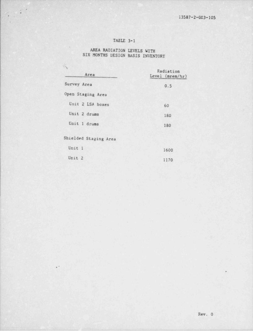
The crea radiation levels calculsted for the variousareas in the ISWSF are given in Table 3-1.
The man-rem assessment combined the radiation fieldsdescribed above with each of the handling, maintenance, and vehiclesurvey activities. The evolutions evaluated included transit of aloaded vehicle from Unit 1 or Unit 2 to-the ISWSF, placing the con-tainers in storage, removing the containers from storage to the shipmentvehicle at a later point in time, and a health physics survey of theshipment vehicle.
Assuming that the man-rem exposures from the ISWSFactivities control the number of workers required to conduct materialhandling operations, the follcwing approximate number of personnel wouldbe required for the operation of this facility during the year:
.-9
|2J - ~, Rev. 2
- . __

.--
[V ?, p i ,.'gf-
-
...
'
. _
- - '13587-2-G03-105t
Number of- Dose perFunction Workers Worker .
Health' Physics .1 .5 rem--Technicians
'I orklift Operators 4 4 rem (max.)F
All other functions 1 equivalent 5 rem total(laborers, truck worker-drivers, maintenancepersonnel)-
.
n*
O
f
e .-1 9
$,
f
4
3-8 Rev. 2 |2.
[ y ,, -,----w-y---y w - p _ km w w*-'Y e''"" '-***'*-"""'*''~"#''' *I '
p. -
,7 * |'
x. .
, , _
13587-2-G03-105'.
,
'r. , .
i
~ TABLE 3-1 !
'
AREA RADIATION LEVELS WITH-SIX MONTHS DESIGN BASIS INVENTORY
,
1
'..; '(.
'' ~~ ~ ~Radiation
' Area Level (mrem /hr)
Survey Area . 0.5
Open' Staging Area
Unit 2 LSA boxes 60
Unit 2 drums 180
Unit I drums 180
Shielded Staging Area
-Unit 1 1600
Unit 2 1170
i
.
$
.
9
Rev. 0
.
.. -- - ,:. - , . . . . - - - - - - - , - - - - - - - - - - - - ~ ' - ~ ' ' ''

, . -__
--
, _ , , , , p.#% . - - * * * ~ - - * - * - * - ^ ~ ' ' * ^ ' ' ' ~ ~ '
r..
* *.
13587-2-G03-105.
I
4.0COMPARISON WITH PROGRAMMATIC ENVIRONMENTAL IMPACTSTATEMENT (PEIS)
j
Section 9.2.1.1 of the PEIS describes a facilityfor the temporary storage of certain low level radioactive wastes. - The
. contents of--the facility are given in Table 4-1. The radiation levels '
at the fence sperounding the facility will be less than 0.6 mrem /hr.'
This facility is judged in Section 9.5.1.2 of the 'PEIS to havenegligible environmental exposures to the general population.
There are some minor differences between the ISWSF '
described in this report and the facility described in the PEIS.These differences are primarily in the number of containers to be storedin the ISWSF. Table 4-1 contains the design basis contents of theISWSF. However, as shown in this report, the ISWSF will result innegligible environmental exposures to the general population.
.-
.
4-1 Rev. 0
- - n . +! ,, . . , _ .__ . . _ _ , . _ . _ _ . _ . . _ . _ _ _ __

,,
_:; - | A.. . - , -.A_
,.~
~.
-- - --- - - - - -
:- .
*"' ' ''--
j13587-2-G03-105 -'
<,
. ..
TABLE 4-1
CONTENTS OF STAGING FACILITY
PEIS Facility. ISWSF,
:;
.. 55-Gallon Drums' 800- 810
LSA Boxes 150' 90(4'ft x 3 ft x 6 1/2 ft) (4 ft x 4 ft x 7 ft);
wooden metal.
50-ft3' Liners 60 -60
,
f
/-
4
1
4
;
i
,
4
I -
.-4
l
.
I1
Rev. O j
l3
- _ _ _ . _ - _ - _ - _ _ . . _ _ _ _ . _ ,_.-

_ - -.
. , .; L__., ; - - - - ~ - - -= - ~ ~ - -
,
y- -
13587-2-G03-105.:--
'5.0 SAFETY EVALUATION+
10 CFR 50, parag,raph 50.59, " Changes, Tests, and Experi-meats,". permits the. bolder of an operating license to make changes' tothe facility provided the change does not involve a modification of theplant technical specifications and the change is determined not to bean unreviewed safety question. As summarized below, the operation ofthe ISWSF neither requires a modification to the plant technical specifi-cations nor is it deemed to be an unreviewed safety question as definedin 10 CFR 50, paragraph 50.59.
5.1 Technical Specifications
There are no Recovery Technical Specifications regardingthe storage of solid or . solidified radioactive waste. The proposedchange does not require any additional technical specifications in orderto satisfy the licensing basis of the plant. Therefore, the operationof the ISWSF does not require changes to the existing technical specifi-cations.
5.2 Unreviewed Safety Question
The operation of the ISWSF will not increase the prob-ability of occurrence or the consequences of an accident or malfunction
,of equipment important to safety previously evaluated in the safetyanalysis report. This is based on the location of the facility beingsuch that- there is no interface with existing safety-related equipmentor structures. ,
"
The possibility of an accident or malfunction of adifferent type than any evaluated previously in the safety analysisreport will not be created by the operation of the ISWSF. This is dueto the passive nature of the facility and the fact that all the radio-active waste is in either a solid / solidified or fixed form.
As stated in Section 5.1, the operation of the ISWSFwill not result in a reduction in the margin of safety as defined in thebasis for any technical specification.
Based on the above, the operation of the ISWSF is deemednot to be an unreviewed safety question as defined in 10 CFR 53, para-graph 50.59.
.-P
e
5-1 Rev. 0,
. ,_ - - _ . _ _ . ._ _ __ _. _ . _ _ . . _ , _ . _ . . _ , , _ _ _ . _ . _ . , _