gp2y0a series / gp2y0d series application · pdf filegp2y0a series / gp2y0d series application...
TRANSCRIPT

GP2Y0ASeries / GP2Y0DSeries
Attachment-1
Sheet No.: OP14030EN
GP2Y0A Series / GP2Y0D Series Application Note
Content Page
1. General description 2
2. Measuring principle and features of this sensor
2-1. Principle of triangulation 2
2-2. features of the GP2Y0A Series / GP2Y0D Series 2
3. Attended issues in use
3-1. Direction of the reflective object 3
3-2. Moving direction of moving reflective object 3
Example of the detectable area characteristics 4
3-3. External disturbing light resistance characteristics 5
Example of the external disturbing light resistance characteristics 6
3-4. Output at glittering reflective object
3-4-1. In case of glittering reflective object with no diffused reflective light ingredient
(Mirror, Glass etc.) 5
3-4-2. In case of lustrous reflective object with diffused reflective light ingredient
(Paint metal, Colored vinyl etc.) 5
3-5. Ambient temperature 7
Example of the temperature characteristics 8
3-6. Optical conditions in front of the sensor 7
4. Characteristics of GP2Y0A Series / GP2Y0D Series
4-1. Characteristics of GP2Y0A Series 9
4-2. Characteristics of GP2Y0D Series 10
5. Supplement
5-1. Modification of the measuring range 11

GP2Y0ASeries / GP2Y0D Series
Attachment-2
Sheet No.: OP14030EN
1. General Description
This GP2Y0A Series / GP2Y0D Series application note has been completed by preparing several characteristic
data for customers’ convenient reference when the GP2Y0A Series / GP2Y0D Series are used.
Please utilize this application note for customers’ design. This application note should be for reference,
however please make sure them in actual mounted condition before using.
2. Measuring principle and features of this sensor
2-1. Principle of triangulation
Optical spot position on PSD shall be changed when reflective object is at “A” point and a “B” point.
By processing this optical spot position electrically, the position (distance) of the reflective object on
straight line can be detected.
2-2. Features of this GP2Y0A Series / GP2Y0D Series
1) Compact high performance distance measuring sensor with built-in PSD, Infrared LED and signal
Processing circuit.
2) No need to input signal, it can be handled easily.
3) Little influence by color and reflective ratio of the reflective object.
4) High accuracy measuring by sequential position detection and mean processing data output.
GP2Y0A Series
・Output voltage depending on the reflective object distance can be got by analog voltage output.
・Shipping after correcting the output deviation of the distance by SHARP.
GP2Y0D Series
・1 bit(H/L) output type.
・Shipping after adjusting the detecting threshold distance by SHARP.
・Adjusting the detecting threshold distance by customer’s demand is also possible.

GP2Y0ASeries / GP2Y0D Series
Attachment-3
Sheet No.: OP14030EN
3. Attended issues in use
3-1. Direction of the reflective object
In case that reflective object has boundary line which material or etc. are excessively different,
in order to decrease deviation of measuring distance, it shall be recommended to set the sensor that the
direction of boundary line and the line between emitter center and detector center are in parallel.
3-2. Moving direction of moving reflective object
In order to decrease deviation of measuring distance by moving direction of the reflective object, it
shall be recommended to set the sensor that the moving direction of the object and the line between
emitter center and detector center are vertical.
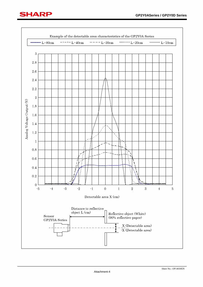
Distance area vs. moving object example of characteristics are the next page.
The GP2Y0A Series in the flowing figure, it in dictates analog output voltage for each reflective object
distance at the detectable area at X=0cm. The reflective object edge shows the change of analog output
voltage when it moves from the lens center. For example, the detecting H/L threshold voltage at X=0cm
shall be about 0.95V, if the detecting threshold distance shall be adjusted at L=30cm, then, the detectable
area at the reflective object distance L=10cm has the range (about -1.1cm to +1.1cm) where the
characteristics at L=10cm cross at the threshold voltage (about 0.95V).
GP2Y0ASeries / GP2Y0D Series
Attachment-4
Sheet No.: OP14030EN

GP2Y0ASeries / GP2Y0D Series
Attachment-5
Sheet No.: OP14030EN
3-3. External disturbing light resistance characteristics
If the direct light from light source such as the sun, Tungsten lamp etc. comes into the detector surface,
there are cases that it can not measure exactly.
Please consider the design that the direct light from such light source does not come into the detector surface.
External disturbing light resistance characteristics of the GP2Y0A Series as example is shown in the
following page.
3-4. Output at glittering reflective object
3-4-1. Incase of glittering reflective object with no diffused reflective light ingredient (Mirror, Glass etc.)
LED light beam has an expanse.
Therefore, incase that there is glittering reflective
object at “A” point in the right drawing, the
glittering reflected light comes into the detecting
device from “B” point and it shall be the same
output when there is the diffused lustrous reflective
object at “C” point, so that accurate measuring is
not possible.
In addition, in case that a glittering reflective object
inclines at “A” point as the center by , the glittering
reflected light comes into the detecting device from
“D” point and it shall be the same output when there
is the diffused lustrous reflective object at “E” point,
so that accurate measuring is not possible.
3-4-2. In case of lustrous reflective object with diffused reflective light ingredient
(painted metal, Colored vinyl etc.)
In case that lustrous reflective object with diffused reflective light ingredient shall be measured,
accurate measuring for the distance between the sensor ad the object is possible by tilting the
lustrous reflective object like the following drawing since the glittering reflective light ingredient runs
away to “Y” direction and the diffused reflective ingredient comes into the detecting device (PSD).

GP2Y0ASeries / GP2Y0D Series
Attachment-6
Sheet No.: OP14030EN

GP2Y0ASeries / GP2Y0D Series
Attachment-7
Sheet No.: OP14030EN
3-5. Ambient temperature
Example of ambient temperature characteristics if the GP2Y0A Series as example is shown in the
following page.
3-6. Optical conditions in front of the sensor
1) Please consider that there is no object which interrupt the LED beam from sensor or no object
which interrupt the reflective light from the reflective object to the detector portion.
2) In case that an optical filter is set in front of the sensor, the filter must have high transmittance with
emitted spectrum wavelength of LED ( =850nm +/-70nm) which is used in the sensor, please use
the filter whose surface is face and back mirror. (When there’s like sand brushing on the surface,
there is a case that the light is diffused inside of the filter, so the filter is sometimes detected.)
Also, the clearance between the sensor and the optical filter should be set at 1mm or less. In case
that the clearance is 1mm or more, in order to avoid the light emitting from the filter to the detector,
which is emitted from LED and is glittering reflected by the filter, the following would be
recommended.
a) Set a tube to the filter on emitter side
b) Set a shading board between emitter lens and detector lens.
When an optical filter is used, please use it after confirming the operation in actual application.

GP2Y0ASeries / GP2Y0D Series
Attachment-8
Sheet No.: OP14030EN

GP2Y0ASeries / GP2Y0D Series
Attachment-9
Sheet No.: OP14030EN
4. Characteristics of GP2Y0A Series / GP2Y0D Series
4-1. Characteristics of GP2Y0A Series
GP2Y0A Series is an analog voltage output type distance measuring sensor and detects the analog voltage
depends of the distance from the reflective object.
Output voltage vs. distance and vs. reciprocal of distance examples of characteristics are the following.

GP2Y0ASeries / GP2Y0D Series
Attachment-10
Sheet No.: OP14030EN
4-1. Characteristics of GP2Y0D Series
GP2Y0D Series is 1 bit (H/L) output performance type distance measuring sensor, and it’s able to
detect the reflective object at the set-up detection distance (L=24+/-3cm).
Also, this GP2Y0D Series type has a hysteresis width at the detection distance and has no area, where
the output is unstable like the distance measuring sensor currently in use. Therefore, the stable output
of H or L is acquired.
Example of output distance characteristics are the following.

GP2Y0ASeries / GP2Y0D Series
Attachment-11
Sheet No.: OP14030EN
5. Supplement
5-1. Modification of the measuring range
The following expression shall be realized by
geometrical relation among the distance to the
reflective object : “L”, Base line length : “A”,
Focal distance of the lens : “f” and Optical spot
position on PSD : “X”,
X=(A*f)/L
For example, when possible measuring range
would like to be changed without any change of
PSD detector size, it can be realized by changing
the base line length : “A” or the focal distance of
the lens : “f”, Current distance measuring sensors.