governors island park and public space
TRANSCRIPT

www.haleyaldrich.com
1Hart Crowser, a division of Haley & Aldrich, 3131 Elliott Ave, Suite 600, Seattle, WA 98121; email:
2 Hart Crowser, a division of Haley & Aldrich, 3131 Elliott Ave, Suite 600, Seattle, WA 98121; email:
Governors Island Park and Public Space
New York’s Most Unconventional and Resilient Hills David G. Winter, P.E., LEED AP, M.ASCE
1
and Brice Exley, P.E., M.ASCE 2

1
ABSTRACT
Over a 10-year period much of Governors Island in New York Harbor was planned, demolished, designed, and
redeveloped to create a destination park in an unmatched setting. The Trust for Governors Island oversaw a diverse
team of designers and engineers working within a transparent public process to create this highly acclaimed new
playground and education resource for one million annual visitors.
INTRODUCTION
Hart Crowser, a division of Haley & Aldrich (HCHA), used engineering and analytical creativity and a commitment
to sustainable design to convert the flat and languishing landscape of Governors Island into a series of wandering
pathways, inviting recreational areas, and surprising hills with unmatched views. Located just a 7-minute ferry ride
and less than a half mile from the tip of lower Manhattan, Governors Island (Figure 1) has a unique history and
unique location at the mouth of both the Hudson and East Rivers while overlooking New York Harbor. On a mass
of deep and unstable soft soil, HCHA worked with the project team to develop a cost-effective way to safely build
hills with steep slopes as high as 80 feet above the harbor right next to the seawall and sloping shoreline. The
seawall itself was rebuilt as part of the redevelopment project, re-armored to weather 3 feet of potential sea level
rise, and recycled to create a fun feature on the tallest hill. Sequencing required that the new seawall be built
before the nearest hills, necessitating hill design and construction solutions that protected the new seawall. HCHA
designed composite hills from different types of fill including recycled demolition debris, lightweight fill to reduce
the weight on the soft subsoil and manage the deformation of the new seawall, and planting soil to allow
vegetation to take root quickly and permanently. This engineering feat and resilient construction allows visitors to
take in an unobstructed view of the face of the Statue of Liberty, the Verrazano-Narrows Bridge, the New York
City skyline, and the Brooklyn Bridge – all from the unexpected height of an 8-story building.
FIGURE 1. GOVERNORS ISLAND IS JUST SOUTH OF LOWER MANHATTAN
HISTORY AND CONDITIONS LED TO REDEVELOPMENT CHALLENGES
The northern 69 acres of Governors Island is natural and original – an outcrop of rock in New York Harbor and the
East River about a half mile off the south tip of Manhattan. It has been used as a fort, an armory, and a POW camp
in the Revolutionary and Civil Wars. Even before that it was a fishing camp for local tribes, and a fort and sawmill
for the Dutch. It was eventually renamed Governors Island while being reserved for the “benefit and
accommodation of His Majesty’s Governors.” It was expanded from approximately 69 acres to 172 acres more

2
than 100 years ago by dumping 4.8 million cubic yards of hydraulic fill excavated for an extension of the Lexington
Avenue subway. In the middle of the 20th century this area became the largest United States Coast Guard station
in the country, complete with barracks, officers housing, recreational facilities, a runway, and industrial/supply
centers (Figure 2). President Reagan, President-Elect Bush, and President Mikhail Gorbachev held a summit at
Governors Island in 1988. But by the start of the 21st century the military was gone, and Governors Island
languished – an abandoned and underused jewel with an unbelievable setting.
FIGURE 2. ABANDONED MILITARY BUILDINGS
A joint city-state agency called GIPEC, Governors Island Preservation and Education Corporation, was responsible
for activities on the island after the Coast Guard left, but the City of New York took over the redevelopment and
GIPEC was succeeded by the Trust of Governors Island (Trust), which operates on behalf of the Mayor’s Office and
managed the master planning, design, and redevelopment, and still operates all activities on the island today.
West 8’s Master Plan set the stage. The redevelopment of Governors Island began with the selection in 2007 of a
Dutch landscape architect and urban design firm, West 8, hired to transform the flat landscape of abandoned
buildings and ball fields on the southern part of the island and connect it with the classic military buildings of the
historic north. One of West 8’s first recommendations were that the southern part of the island be raised up
significantly, using terms like “sustainability” instead of the now-familiar “sea level rise” and “resilience.” Coming
from Holland, a country within just a few feet of the sea levels, West 8 had relevant first-hand experience, and
knew the importance of matching a design to the surroundings.
West 8’s master plan called for a gently rolling park with meandering pathways and recreational areas linking the
northern natural part of the island with the man-made southern part. The entire island would be ringed by a wide
promenade at the top of a reconstructed seawall. South of the park, West 8 laid out four tear-drop shaped hills
rising 26 feet to 80 feet above the island surface. These hills were not just big piles of dirt. They were shaped to
frame pathways, create steep slopes to enhance the experience, and allow visitors an unobstructed 360-degree
view of the New York skyline, the Statue of Liberty, Brooklyn, and New York Harbor.
But West 8 was unhappy with some of the “building-like” preliminary design solutions proposed by engineers on
their master planning team. They reshuffled that team for design, and HCHA of Seattle, Washington was hired to
help turn the vision and master plan into a constructible reality. (Also hired was MKA, also of Seattle, who had
worked collaboratively with HCHA on the highly awarded and in many ways similar waterfront Sculpture Park in
Seattle).
Assessment of subsurface conditions. HCHA reviewed subsurface information from explorations and summaries
done previously on Governors Island by Langan (2005) and Dewberry-Goodkind (2006). These data provided a
good starting point of the likely conditions that would guide the final design. Over three mobilizations between

3
2010 and 2013 HCHA progressively identified and filled data gaps to create a comprehensive understanding of the
nature and variability of the soils across the site. HCHA explorations included 25 onshore borings, 16 onshore
cone penetrometer probes, 6 groundwater monitoring wells, 4 infiltration tests, and many shallow test pits. In
addition, the work included 3 offshore borings and 3 offshore cone penetrometer probes (CPT). There was a
higher strength “crust” at and just below the ground surface. The explorations then showed a variable amount of
recent fill – typically about 20 to 35 feet – above an upper soft clay. The clay was 5 to 30 feet thick and was above
a loose to medium dense sand that varied from 20 to 30 feet thick. Below that was a second even softer clay unit
as thick as 55 feet (Figure 3). Standard Penetration Test (SPT) blow counts were often 0 in the material, and
normalized cone tip resistances, Qt, were about 3 to 5. The lower clay had interbedded thin sand layers. At a
depth of about 125 feet near the shoreline and 110 feet farther inland, the soft clay gave way to very dense glacial
till and hard clay, and bedrock. Groundwater was at about elevation 4 feet and was not significantly influenced by
harbor tide changes.
FIGURE 3. GENERALIZED SUBSURFACE CROSS-SECTION
Laboratory testing included index tests, incremental and constant rate of strain consolidation tests, triaxial
compression, and direct simple shear. Table 1 summarizes soil properties developed from the field and laboratory
testing and used in the analyses. Stratigraphy, layering of drainage zones within the clay, proper identification of
the friction angle of the sandy soils, and the shear strengths of the fine-grained soils governed the analyses.
TABLE 1—SOIL PROPERTIES USED IN DESIGN Soil Layer Total Unit
Weight (pcf) Effective Friction Angle (deg)
Normally Consolidated Shear Ratio
Fill Sand 102 33 -
Upper Silt/Clay 108 31 0.26
Native Sand A 111 36 -
Native Sand B 111 36 -
Normally Consolidated Sandy Clay 109 27 0.23
Hill Fill 135 40 -
Expanded Aggregate 60 42 -
Offshore Silts 108 32 0.26
Seawall/RipRap 115 36 (c’=20 pcf) -

4
The friction angle was estimated by a combination of STP correlations (Hatanka and Uchida 1966, Schmertmann
1975) and CPT correlation (Kulhawy and Mayne 1990). The initial undrained shear strengths were estimated by
considering CPT correlations using Nkt=15, plasticity index, typical published SHANSEP parameters (Ladd 1991), as
well as CU and UU triaxial tests. Preconsolidation pressures were determined from consolidation tests on Shelby
tube samples. The resulting initial undrained shear strengths were plotted together in an effort to cross-check
each method. A trend of shear strength closely fitting a shear ratio of 0.22 as recommended by Ladd was
observed. These values were later refined using the effective stress derived friction angle of the fine-grained soils
using the CPTu and critical state soil mechanics under the direct simple shear stress path as well as direct simple
shear tests, which is reflected in Table 1. An example of the comparison between the CPT derived and direct
simple shear test normally consolidated undrained shear strength ratios are provided in Figure 4.
FIGURE 4. COMPARISON OF CPT AND DIRECT SIMPLE SHEAR STRENGTH TEST RESULTS
Strength increase from consolidation was calculated by combining the undrained shear strength ratios with an
estimate of the increase in effective stress using Boussinesq theory through the use of the program SAF-I, which
was subsequently changed to Settle3D and SLOPE/W to better model the three-dimensional stress effects of the
hills on the subsurface layering. These were later supplemented with both 2D and 3D finite element models. For
the limit equilibrium analysis, the shear ratio and increase in effective stress were used to calculate an undrained
shear strength in multiple zones (middle and edges of the hill) in SLOPE/W. Preloaded areas around the hills were
incorporated into the stress history of the soils using the SHANSEP approach. Deformation characteristics and
consolidation rates were determined from one-dimensional consolidation and dissipation tests for fine-grained
soils, and in situ correlations for coarse-grained soils. Permeability was estimated from grain size correlations and
CPT dissipation tests. Subsequently HCHA completed paired borings and CPTs to better correlate the
understanding of conditions. The CPT soundings also included shear wave measurements. Higher quality
undisturbed samples were obtained using an Osterberg piston sampler, with the samples subjected to direct
simple shear and CU triaxial compression, as previously mentioned.
Master Plan immediately faced design and construction hurdles. West 8’s inspiring master plan brought with it
several obstacles, none bigger than the potential instability from the depositional history of the soil below the
ground surface. As described above, the combination of harbor sediments and hydraulically placed fill had
resulted in an average of 100 feet of soft, under-consolidated soil beneath the southern half of the island – right
below the planned location of the hills.
5
The HCHA team immediately identified three primary challenges:
1. The subgrade was going to consolidate significantly over time from the weight of fill placed to build hills
as high as 80 feet above grade. The weight of the fill, when applied to soft and compressible soils not only
causes major settlement, but both the irregular shape of the hills and the irregular layering of the soils
meant large and variable settlements, at hard to predict rates. The settlement in turn creates uneven
ground surfaces and adds to the fill quantities (and weight) needed to reach the final grades.
2. West 8 didn’t just envision the hills to be big piles of dirt. They planned elegantly shaped hills with over
steepened slopes to frame pathways and enhance views. With constructed slopes as steep as 1.25H:1V
the hills had to be built and the surfaces reinforced to keep localized steep slopes stable both during
construction and long term.
3. Perhaps the most important design challenge was maintaining the global stability of such a large mass of
fill with such steep slopes above such a thick layer of soft soil. Naturally, the best spot for the steepest
slope creating the best view was right next to the seawall, with the sloping shoreline beyond. But without
careful control of the construction sequencing which incorporated monitoring of the response of the
clays, the soft soil wouldn’t support the steep hill. The man-made hill on the man-made fill wanted to
slide into the harbor.
These were by no means the only challenges the design and construction team faced:
• Traditional construction truck transportation on and off the island was not desired or efficient. Everything
had to be barged in and out to the single available pier where it could be loaded onto trucks that stayed
on-island throughout construction.
• Demolition of nine buildings and thousands of square feet of pavement created mountains of
construction debris that the Trust wanted to recycle.
• The existing seawall was crumbling and would be rebuilt just ahead of the hills.
• Thousands of trees and shrubs needed to quickly take root to help armor slopes in the harsh saltwater
environment.
SCHEMATIC DESIGN, DESIGN DEVELOPMENT, AND FINAL DESIGN
Slope stability analyses. HCHA used both limit equilibrium methods (SLOPE/W) and finite element analyses
(PLAXIS 2D and 3D) and worked towards minimum factors of safety of 1.25 for the unconsolidated, undrained
condition during construction and 1.35 for the fully consolidated and drained post-construction condition
(AASHTO Bridge Design Manual 2010).
HCHA developed or adapted the methods to model the performance of the hills, incorporating the unlikely
combination of layout, conditions, and design vision creating interwoven complexities that pushed traditional
park-like solutions to evolve. HCHA recognized that the subsurface soils could not support the weight of the fill
required to build the largest hills and maintain key features without causing excessive settlement or sliding. The
subsurface needed to be stronger or the hills needed to be lighter. The team first looked at ways to add strength
to the subgrade, but traditional ground improvement solutions were not cost-effective to the required depths.
The assessment centered on the naturally occurring shear strength gain in soils that comes from consolidation,
and building a reinforced fill that allowed construction of steep slopes and forced the potential critical failure
surfaces farther back from the face of the slope. To test the theory that thin sand layers within the deep soft clay

6
would speed consolidation and strength gain, HCHA devised an instrumented test fill that confirmed the theory
and allowed staged construction rates to increase and thus become more viable. Unfortunately, these solutions
were still not enough. The hills had to be lighter.
The four hills were called Grassy (40 feet above sea level), Slide (45 feet above), Discovery (57 feet above), and
Outlook (90 feet above). Outlook has the steepest (1.25H:1V) and tallest slopes facing and right next to the
seawall. Figure 5 shows the layout of the hills, and some of the explorations completed and sections developed to
identify the subsurface conditions.
FIGURE 5. HILLS LAYOUT AND SUBSURFACE EXPLORATION CROSS-SECTION LOCATIONS
The steepest slopes on Outlook Hill faced the seawall/harbor and the adjacent Discovery Hill to the south. HCHA’s
adapted three-dimensional finite element models more accurately reflected the layout and predicted the
settlement and slope stability performance of the subgrade and hill materials. The model parameters were
regularly updated, and the analyses rerun and reported as the West 8 designers made changes to layout and
sloping to better meet the Trusts’ objectives and refine their design. Over the course of the project, the 3D model
and the analyses evolved to increasingly reflect the actual conditions of the design and in the field. There were
also non-traditional factors to consider:
1. New York’s geology includes glaciation, and there was some nearby evidence that the past movement of
glacial ice in this region had resulted in deep varved clays, and potential planes of weakness that could
drive the global slope stability safety factor below 1.0. The potential for varved layers was assessed but no
such surfaces were found, suggesting a slightly different depositional history than in other nearby areas.
2. New York is in a moderate risk earthquake zone, requiring ground shaking forces in the analyses. The
design earthquake was an event with a 10 percent probability of exceedance in 50 years with a design
factor of safety of 1.1.

7
3. The saltwater environment in the harbor was harsh and could be difficult on trees and shrubs but an
important long-term benefit from the planned vegetation was the increased slope face stability the roots
provided.
4. From the beginning West 8 was focused on potential sea level rise. They determined that the park and
hills should be specifically designed for a minimum of 3 feet of sea level rise. When combined with the
wind and wave design criteria from a major storm it was evident that these additional factors could be
just as important to the stability of the hills as soil strength and fill placement.
There were many ways to achieve the required factors of safety, but they had to fit the West 8 vision and the
Trust’s budget.
Progressive solutions. Many different potential solutions to the global slope stability were initially considered and
discarded. Several were discarded because they were too expensive or inefficient (e.g. pile supported
embankments, and closely spaced wick drains). Some potential solutions would not play well with the public or
the exciting master plan (shorter, more rounded constructed elements that were more like mounds than hills).
West 8 wanted simple and straightforward solutions that would result in hills that were safe, natural in
appearance, constructible within the budget guidelines, and resilient over time.
The schematic design solution to the steep slopes and heavy hills adjacent to the shoreline included a pair of
below-grade 8-foot-wide deep soil mixing (DSM) cutoff walls (Figure 6), staged construction that required a full
year of consolidation time, and Geofoam blocks to reduce the weight. While this combination of solutions met the
factor of safety requirements for global stability, West 8 and the Trust were clearly not enamored with it, and it
was significantly more expensive than the budget allowed.

8
FIGURE 6. SCHEMATIC DESIGN SOLUTION WITH CUTOFF WALLS
Thinking creatively, the engineers realized that the solution might also involve a matter of perspective. The hills
were originally planned to be about 10 feet taller (as shown in Figures 5 and 6). But after being lifted high in a
construction crane the West 8 team and the Trust representatives agreed that the views were just as spectacular
at a maximum height of 80 feet above the harbor, and the hills were proportionately lowered by about 10 feet.
This reduced the weight, and together with other engineering adaptations, led to the final solution, and hills built
to 30 feet (Grassy), 36 feet (Slide), 49 feet (Discovery), and 80 feet (Outlook) above sea level.
Key components of the evolving design development solution included:

9
Reuse of construction debris. Approximately 300,000 cubic yards of fill was required to construct the four hills
and park. Demolition of nine buildings and associated paved surfaces resulted in about 50,000 cy of debris. The
Trust and West 8 wanted all this material to be incorporated into the hills. HCHA established criteria for reuse and
the contractors set up crushing/processing units on the island. All 50,000 cy of debris—including concrete,
reinforcing steel, brick, and asphalt—were used as fill within Outlook Hill, back away from the shoreline. Recycling
thus saved 50,000 cy of material from being hauled off and 50,000 cy from being brought onto the island, for a
total of 100,000 cy.
Lightweight fill. Traditional fill and construction assumptions would make Outlook and Discovery Hills very heavy,
with concentrated loads from steep slopes located less than 50 feet from the seawall/shoreline. Even if the rate of
construction were limited to allow pore pressure dissipation and strength gain, stability was a problem. In
addition, settlement and lateral movement around the hills and along the seawall were still significant, even with
the 10 feet lower hills redesigned by West 8. The Geofoam blocks idea (with enough soil cover to keep the hills in
place during the design storm and earthquake evens) was seriously considered. Although Geofoam had a good
record of performance in subgrade applications, there was less confidence in their long-term performance as
building blocks for elevated surfaces. And a more limited use of Geofoam within the middle of the hills did not
provide enough weight relief to justify the comparatively high cost. HCHA talked with local suppliers about
lightweight granular materials, included naturally occurring waste products and manufactured products. With
several similar products easily available for barge transport to the island, the lightweight aggregate was selected.
Final design included about 70,000 cubic yards of high-strength lightweight fill (Figure 7) used in a modeled and
prescribed zone of the hill (the lighter shade material in the photograph below) to reduce deformations at the
shoreline and seawall and increase the global factor of safety.
FIGURE 7. LIGHTWEIGHT FILL INSTALLATION AND OUTLOOK HILL COMPLETED
Buttressing. The steep slopes of Outlook Hill faced the shoreline, the north park, and Discovery Hill to the south.
Discovery also had steep slopes and the combined weight resulted in a critical stability condition in multiple
directions. Buttressing these steep slopes allowed consolidation and resulting strength gain to occur, thus
increasing the safety factors. For example, at the north side of Outlook the park and slope up to the hill were
constructed more than a year before Outlook construction began. At the south side Discovery Hill construction
was designed to progress ahead of Outlook, with both hills ultimately buttressing each other.
While difficult to reliably define the extents, it was documented that the southern portion of the island was
constructed by placing rip rap seawall around the eventual footprint of the expansion to contain the placement of

10
the hydraulic fill. The stiffness and strength of the historic rip rap revetement (and rebuilt seawall) was important
to the stability of Outlook and Discovery Hills, as it provided a relatively stiff and heavy material near the toe of
the slopes.
Staged construction. Consolidation and strength gain take time. HCHA estimated time rates of consolidation
based on the soil layering and permeability observed in the continuous CPT soundings and constant rate of strain
consolidation tests. These were incorporated into the limit equilibrium models and finite element models to
calculate the anticipated maximum rate of construction. For Outlook and Discovery, some type of staged
construction was required to achieve the necessary safety factors.
MSE geogrids. Widespread use of mechanically stabilized earth (MSE) geogrids as a component of global stability
was a concept developed in collaboration with Tensar. All slopes steeper than 2H:1V were designed with the use
of the MSE for face stability. HCHA and Tensar developed an application of the geogrids to strengthen the placed
fill and force the critical failure surface back farther into the hill. Although theoretically effective, this approach
was not ultimately relied upon because the combination of lightweight fill, construction staging, and the ability to
confidently model the beneficial 3D effects increased safety factors to acceptable levels.
Ground settlement. HCHA estimated settlement response using Settle3D and PLAXIS 3D as well as traditional one-
dimensional consolidation theory. At full construction and 95% consolidation the hills were predicted to settle
between about 3.5 feet (Slide and Grassy) to 6 feet (Discovery) to 8.5 feet (Outlook), which is shown on Figures 8
and 9. This settlement would occur over about four years. The settlement was generally linked to height of the
hill, but also varied by type of material and steepness of the slopes, and other geometry. Even though the
expected settlements were significant they were not abrupt, and flexible utility connections could be designed to
withstand the movements.
FIGURE 8. MODELED SETTLEMENT DURING CONSTRUCTION

11
FIGURE 9. MODELED SETTLEMENT AT 95% CONSOLIDATION
Based on instrumentation installed during park construction (completed two years before the hills), the rate of
consolidation was observed to be faster than the laboratory and CPT tests indicated. This observational approach
helped refine the design of the hills staged construction, which was then confirmed by in situ instrumentation
installed to monitor construction progress.
Planting soil. Working with the landscape architect and Tensar, HCHA devised a mix of soil and layout of geogrids
at the face of the steep slopes that allowed about a 5-foot thickness of engineered organic soil to be used as a bed
for vegetation without a reduction in the face stability. The design was also “smooth” enough so that it did not
appear stepped, but mature shrubs and small trees could quickly take root and further stabilize the steep slopes.
Seawall reconstruction. At the same time as design of the hills, the seawall around the island was rebuilt as more
of a natural and gradual revetted surface. In keeping with the island theme of recycling as much waste as possible,
many of the replaced granite seawall blocks were reused as fill or features, including the “scramble” (Figure 10) to
the top of Outlook that is wildly popular with kids.

12
FIGURE 10. SCRAMBLE ON OUTLOOK HILL
The movement of the subsoil around and below the hills could have caused movement of the seawall. As shown
in Figure 11, HCHA predicted 8 to 12 inches of lateral deflection and about the same amount of settlement. The
revetments and a concrete topping block wall were designed to be easily adjusted if settlement was excessive.

13
FIGURE 11. ESTIMATED EXTENT OF LATERAL DEFORMATION AT OUTLOOK HILL AND SEAWALL
Drainage and resilience. All construction materials were designed to quickly drain precipitation, water from
waves, and water from an overtopped seawall. Infiltration tests done early in design gave HCHA good parameters
for the shallow subgrade, and drainage characteristics for the various types of fill were checked and correlated to
the design gradations and field tests of the actual gradations. As noted earlier, the south part of Governors Island
was designed for a sea level rise of 3 feet over the life of the park, plus the storms that often pummel the East
Coast in the winter months. Stability of the soils and the facing of the slopes in the first 5 to 10 feet of the hills
were given special attention to be sure water could enter and drain freely, without mining fine material from the
matrix. It was also vitally important that vegetation quickly take root and thrive in the partial saltwater
environment of the island in the middle of the harbor. A total of 3,000 trees and 43,000 shrubs were planned for
the park and hills.
14
An underplayed element of sustainability was HCHA’s work sourcing fill for the hills. The team considered material
dredged from the Buttermilk Channel and other maintenance dredged soils. These could provide some
inexpensive materials for reuse as fill, but generally could not be placed without additional on-island processing.
And 25,000 truckloads of fill coming to the island from some other landside location was not socially responsible.
Instead HCHA worked with contractors to source material from Hudson River locations that could be barged
directly to the island. The selected quarry was about 60 miles upriver but didn’t require a single truck to deliver
250,000 cy of fill to the island.
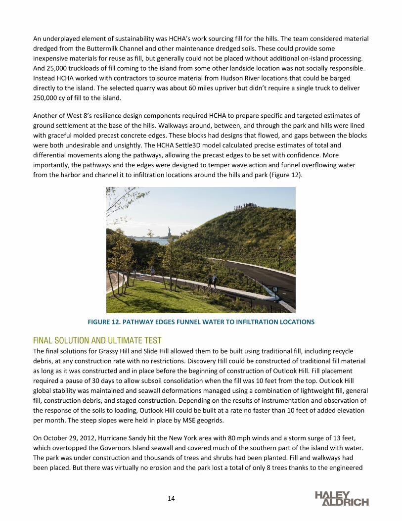
Another of West 8’s resilience design components required HCHA to prepare specific and targeted estimates of
ground settlement at the base of the hills. Walkways around, between, and through the park and hills were lined
with graceful molded precast concrete edges. These blocks had designs that flowed, and gaps between the blocks
were both undesirable and unsightly. The HCHA Settle3D model calculated precise estimates of total and
differential movements along the pathways, allowing the precast edges to be set with confidence. More
importantly, the pathways and the edges were designed to temper wave action and funnel overflowing water
from the harbor and channel it to infiltration locations around the hills and park (Figure 12).
FIGURE 12. PATHWAY EDGES FUNNEL WATER TO INFILTRATION LOCATIONS
FINAL SOLUTION AND ULTIMATE TEST
The final solutions for Grassy Hill and Slide Hill allowed them to be built using traditional fill, including recycle
debris, at any construction rate with no restrictions. Discovery Hill could be constructed of traditional fill material
as long as it was constructed and in place before the beginning of construction of Outlook Hill. Fill placement
required a pause of 30 days to allow subsoil consolidation when the fill was 10 feet from the top. Outlook Hill
global stability was maintained and seawall deformations managed using a combination of lightweight fill, general
fill, construction debris, and staged construction. Depending on the results of instrumentation and observation of
the response of the soils to loading, Outlook Hill could be built at a rate no faster than 10 feet of added elevation
per month. The steep slopes were held in place by MSE geogrids.
On October 29, 2012, Hurricane Sandy hit the New York area with 80 mph winds and a storm surge of 13 feet,
which overtopped the Governors Island seawall and covered much of the southern part of the island with water.
The park was under construction and thousands of trees and shrubs had been planted. Fill and walkways had
been placed. But there was virtually no erosion and the park lost a total of only 8 trees thanks to the engineered

15
soils and planting mix in the upper portions of the fill. Water drained quickly and all areas of the island were
accessible the next day. Construction resumed less than a week later.
SUMMARY OF CRITICAL DESIGN FACTORS
In the 10 years from master planning through opening of the park and hills, several key design factors stood out as
most important to allow successful design, construction, and now 5 years of performance:
1. The varied exploration, sampling, and testing plan identified soil stratigraphy – both what was important
(like the sand seams within the clay) and what was not (varved clay zones of weakness). Confidence in the
understanding of the conditions allowed HCHA to be precise with safety factors.
2. Shear strength of subgrade soils and the undrained strength ratio, Su/P, were the most important factors
in the slope stability analyses.
3. The presence of interlayered sand seams affected the drainage distance for excess pore pressures and
thus the time rate of consolidation that drove the staged construction rate.
4. The ability to barge in 250,000 cubic years of fill, including 70,000 cubic yards of lightweight fill with
strength parameters similar to general fill allowed construction of the tallest portion of the hills to be
close to the seawall.
5. Re-engineered Geogrids allowed construction of steep slopes.
6. The combination and application of the key analysis methods – Settle3D, PLAXIS 2D and 3D, and SLOPE/W
– guided the required extent of lightweight fill, length of Geogrids, allowable rate of construction, and
amount of material needed for final construction.
RESILIENCE IN THE GOVERNORS ISLAND SOLUTIONS
Throughout the planning, design, and construction process, the City of New York, Mayor’s Office; the Trust for
Governors Island; and West 8 consistently emphasized the importance of a sustainable and resilient design. As
noted throughout this paper, some of the team’s responses to help them meet that goal were:
1. Early consideration of the groundwater table and infiltration testing for natural stormwater management.
The master plan included a large area at the extreme south part of the island called a Wetland Garden,
intended to be a collection area for stormwater runoff and tidal fluctuations, with plants that could thrive
in both freshwater and saltwater environments (Wetland Garden not yet constructed but infiltration
included on site stormwater management).
2. The team wanted to minimize truck traffic for material deliveries to the island. HCHA specifically targeted
fill sources and quarries adjacent to waterways to allow all fill to be barged directly to the island.
3. The full design team met regularly to collaborate on alternatives, identify risks, and develop solutions that
balanced costs and performance. HCHA participated in multiple presentations to the Mayor’s Office and
the Trust. Technical peer reviews helped finalize approaches and meet the Trust’s goals. Considerations,
problem solving approaches, and final solutions were public and transparent.
4. The final design included 50,000 cy (more than 15% of the total fill) of recycled and on-island processed
construction debris. No demolition debris was hauled off the island.

16
5. Steep slope MSE walls were modified at the face to provide significant pockets of engineered organic
planting soil that allowed trees and shrubs to quickly take root and naturally anchor the slopes. No
significant erosion occurred during construction, or during the significant storms that took place during
four seasons of the work.
6. All soils were designed to drain quickly. In some cases, this made them a little harder to place at the
proper moisture content, but the result was a highly permeable mass of soil that absorbed stormwater
runoff easily, even with a shallow groundwater table.
7. Pathways and edges were specifically designed to channel excess water to infiltration locations after
precipitation or wave overtopping.
17
References
1. Hart Crowser, Inc. (2011) Geotechnical Engineering Schematic Design Report, Governors Island Park and
Public Space
2. Hart Crowser, Inc. (2013) Volume 1 Geotechnical Baseline Report, Outlook Hill, Governors Island Park and
Public Space
3. Hart Crowser, Inc. (2014) Geotechnical Engineering Final Design Report, Volume 1 Geotechnical Analyses and
Discussion, Governors Island Park and Public Space
4. Hatanaka, M. and Uchida, A. (1996) A Simple Method for the Determination of Ko-Value in Sandy Soils, Soils
and Foundations, Vol. 36, No. 2
5. Kulhawy, F.H. and Mayne, P.W. (1990) Manual on Estimating Soil Properties for Foundation Design
6. Ladd, C.C. (1991) Stability Evaluation During Staged Construction, 22nd Karl Terzaghi Lecture, Journal of
Geotechnical Engineering, ASCE, Vol. 117, No. 4, pp. 540-615
7. Langan Engineering & Environmental Services (2005) Geotechnical Historic Data Report Governors Island
Development
8. Schmertmann, J.H. (1975) Measurement of In-Situ Strength, Proc., ASCE Specialty Conference on In-Situ
Measurement of Soil Properties, Raleigh, NC, Vol. 2, p. 57-138