government of india south western railway...
TRANSCRIPT

1
GOVERNMENT OF INDIA
SOUTH WESTERN RAILWAY
HUBLI
TENDER NOTICE No: SG/SWR/Proj/UBL/UGR-Station
Dated 28.10.2015
Name of the work: Shifting of Up and Down advanced starters outside of slip siding points and shifting of Relays room at Ugarkhurd station.
Copy No. __
Issued to: __
Cost of tender form: Rs. 3405/- In person : Rs. 3905/-- By Post

Signature of the Tenderer 2
INDEX
1. Chapter I- Instructions to Tenderer downloaded from
Internet
2. Chapter II- Check list
3. Chapter III- Tender Notice
4. Chapter IV- Acceptance form
5. Chapter V- Instructions to Tenderer
6. Chapter VI- Special conditions of Contract
7. Chapter VII- Technical Specifications
8. Chapter VIII- Annexures
9. Chapter IX- Tender Schedule

Signature of the Tenderer 3
CHAPTER-I INSTRUCTIONS TO TENDERERS TENDER FORMS DOWNLOADED FROM
INTERNET
1. Tender file is to be down loaded from the internet and printout is to be taken on A4 size paper and details are to be entered by the tenderer at the various locations in the document. It is advisable that the down loaded tender document to be printed through laser printer only. Submission of Xerox or photocopy of tender document is prohibited.
2 .The tender document (in full) downloaded along with the various documents shall be submitted as per the tender conditions in a sealed cover duly superscripting with the name of the work, tender notice No. and date and the same should be dropped in the tender box kept in the Office of Dy.CSTE/Project/HUBLI, S.W. Railway before the date and time stipulated in the tender document.
3 .The cost of tender document as indicated in the tender document will have to be deposited by the Tenderer in the form of Nationalized Bank demand draft payable in favor of FA&CAO/CN/BNC, South Western Railway along with the tender document. This should be enclosed as a separate Demand Draft. A single demand draft for the cost of tender form and Earnest Money Deposit will not be accepted. Tender not accompanied by the above demand draft towards the cost of the tender document will be summarily rejected.
4. The earnest money deposit required for this tender as stipulated in the tender document also to be submitted separately along with Tender document.
5. Tenderers are advised to download the tender documents well in advance and submit the tender before the stipulated time. It is the responsibility of the Tenderer to check for any corrections or any modifications published subsequently in Web site and the same shall be taken into account while submitting the tender. Tenderer shall down load corrigendum (if any), print it out, sign and attach it with the main tender document. Tender document not accompanied by the published corrigendum/s is liable to be rejected. The Railway will not be responsible for any postal delays and delay in downloading of tender document from the internet.
6. The Tenderer may please note that the rate for each schedule should be written in figures and in words in abstract summery which is available in the tender booklet by black or blue ball point pen only. Each page of tender document should be signed by the Tenderer.
7. Tenderer/s are free to download tender document at their own risk and cost, for the purpose of perusal as well as for using the same as tender document for submitting the offer, Master copy of the tender document is available in the Office of Dy.CSTE/Project, S.W.Railway,Hubli –580 020. After award of work, an agreement will be drawn, which shall be executed by the successful Tenderer and this agreement will be prepared based on the master copy of tender document available in the above mentioned office and not based on the Tender document submitted by the Tenderer. In case, any discrepancy between the tender document downloaded from the internet and the master copy, latter shall prevail and will be binding on the Tenderer/s. No claim on this account will be entertained.
8. If any change/addition/deletion is made in the Tender Document by the Tenderer/Contractor and the same is detected at any stage even after the award of the tender, the tenderer’s full earnest money deposit will be forfeited and the contract will be terminated at his/their risk and cost. The Tenderer is also liable to be banned from doing business with Railways and/or prosecuted.
9.. The following declaration should be given by the Tenderer while submitting the tender: Declaration
(a) I/We have downloaded the tender form from the internet site www.southwesternrailway.in and I/We have not tampered / modified the tender forms in any manner. In case, if the same is found to be tampered / modified I/We understand that my/our tender will be summarily rejected and full earnest money deposit will be forfeited and I/we am/are liable to be banned from doing business with Railways and/or prosecuted.
(b) I/We submitting a demand draft no. ___________________ dated
__________ issued by ____________________ for Rs.__________ towards the cost of tender form.
Signature of Tenderer :
Date : Address :

Signature of the Tenderer 4
CHAPTER-II CHECK LIST
CHECK LIST FOR SUBMISSION OF TENDER
Sl. No.
Items Yes No
1. Have you purchased / downloaded the tender document from internet for submission by your firm?
2. Have you submitted cost of tender document in the form of DD or cash receipt, in case you have downloaded from internet?
3. Have you submitted the tender in the Railway’s Form?
4. Have you furnished all requisite documents in English?
5. Have you submitted documents pertaining to status/contribution of the firm, partnership deed and power to attorney?
6. Have you furnished full postal address, telephone number/Fax number?
7. Have you submitted documents pertaining to Earnest Money valid at least up to the date of the validity of the Tender? State whether:
i. Cash deposited in the Railway cash office. ii. Demand Draft/Banker’s Cheques.
8. Have you submitted document of current income Tax Clearance Certificate?
9. Have you kept your offer valid for 120 days or as specified?
10. Have you submitted document in support of the Technical System Qualifying Criteria (Eligibility Criteria)?
11 Have you complied Para wise remarks for technical specifications given in Chapter VII ?
12. Have you submitted your offer inclusive of ED and all other Taxes and duties for the entire schedule?
13. Have you registered with Assistant Labour Commissioner of the area where the work will be done? Necessary license to be submitted with the tender or to be produced before signing of the Contact agreement.
14. Have you attested all the corrections?
15. Have you submitted clause wise compliance of the Instruction to Tenderer special Condition and Technical Specifications ?
16. Have you submitted the bids containing Check List, Tender Notice, Declaration form, Instructions to Tenderer’s, Special Conditions of Contract, Technical Specifications, Annexure, schedule of Works & Offer.
NOTE: The above Checklist is not exhaustive. The Tenderer must go through carefully the entire Booklet and submit the tender compliance of all the conditions/ provisions instructions mentioned therein irrespective of the fact that they have been highlighted in the Checklist or not.
Signature of the Tenderer

Signature of the Tenderer 5
CHAPTER-III Tender Notice
SOUTH WESTERN RAILWAY www.swr.indianrailways.in
Open tender Notice No: SG/SWR/Proj/UBL/UGR-station Dated 28.10.2015 Tenders are invited by Dy.CSTE/Project/UBL for and On behalf of the President of India from reputed contractors with sound financial capability for the following works.
Name of Work Approximate
Value(Rs) Cost of Tender
Documents (Rs)
Earnest money
(Rs)
Date of Opening
Period of Completion
Shifting of Up and Down advanced starters outside of slip siding points and shifting of relays room at Ugarkhurd station.
38,78,860/-
3,000/- +13.5% KST= Total
3405/- in Person.
3000/-+13.5% KST+500
Postal Charge = Total 3905/-
by post
77,577/-
08.12.2015
06 months
1 Tender documents (Non transferable) will be issued from the office of the Deputy Chief Signal & Telecommunication Engineer, Project, S.W Railway Hubli –20 up to 17.00 hrs of the previous working day of the date of opening of the Tender on receipt of written request for the same accompanied by the cash receipt for having deposited cost of the tender document with the Divisional Cashier /Hubli and any other division of S.W.Rly. Bangalore Cantonment, Construction or with any Station Master of South Western Railway.
2 In case Tenderer wish to receive the tender document by post /Courier, they should send
written request accompanied by cash receipt for having deposited , the cost of tender document with the additional courier charges of Rs.500/-.The request for tender document must reach this office at least one week in advance of the date of opening of the tender, however Railway administration does not take any responsibility for delay/Non receipt of the Tender document by the Tenderer due to failure of courier /postal service or time taken in transit.
3 Tenderer can also down load the tender document from the website. Those tenderers , who are participating in the tender with downloaded copy, shall enclose a separate crossed demand draft towards cost of the tender form in favour of Financial advisor and Chief Accounts Officer ,Construction, S.W.Railway Bangalore-560046, without which the tender is liable to be rejected .The Railway does not own any responsibility for any alteration /Omissions in the contents of the tender document while downloading from the web site or other wise No claims on this accounts will be entertained. The administration will not own any responsibility if the website is not opened for down loading the tender document due to any technical snag in the server of the website.
4 The tender documents for the above works will be received and opened in the office of the
Deputy Chief Signal &Telecommunication Engineer (Project) South Western Railway Hubli Tender documents will be received up to 15.00Hrs on the date of opening and will be opened on the same day at 15- 30Hrs .Tenders can also be accepted by post if received before expiry of time of receipt of tender document However , Railway will not own any
Signature of the Tenderer 6
responsibility for delay in postal transit .After opening of the tender the rates will be read out in the open presence of tenderers , present at the time of opening of the tenders .Any tender received after 15-00Hrs. will not be considered for evaluation purpose and such tender will not be opened.
5 If the opening date happens to be a holiday, the tenders will be received and opened on
the next working day at the same time. However, there will not be any change in last date of issue of tender document on this account.
6 Late /delayed tender and tender offers received through post after the time of closing of
receipt of tender documents will be summarily rejected.
7 The Earnest money & Security Deposit:
7.1 The tenderer shall deposit in favour of the Railway official i.e. FA & CAO/CN/BNC, as mentioned in the tender notice towards EMD. Tenderer should submit, along with the tender, requisite Earnest Money Deposit and tenders unaccompanied by requisite Earnest Money Deposit will be summarily rejected. Earnest Money in form of Guarantee Bonds shall not be accepted. The Earnest Money should be in Cash or Banker’s Cheques / Demand Drafts in favour of Financial Advisor and Chief Accounts Officer, (Construction), 18, Miller Road, S.W.Railway, Bangalore-560046 executed by State Bank of India or any of the Nationalized Banks or by a Scheduled Bank.
7.2 The Joint Venture Firm shall be required to submit Earnest Money Deposit (EMD) along
with the tender in terms of the provisions contained in Para 7.1 above.
7.3 The Earnest Money deposit in cash should be made to the Chief Cashier, South Western Railway, Bangalore or to any Station Master of South Western Railway and cash receipt obtained from him should be furnished along with the tender.
7.4 Tenderer shall hold the offer open for a period of 120 days from the date fixed for
opening the same, it being understood that the tender documents have been issued to the tenderer and the tenderer has been permitted to tender in consideration of the stipulation on his part that after submitting his tender he will not resile from his offer or modify the terms and conditions thereof, in any manner not acceptable to the Deputy Chief Signal & Telecommunication Engineer (project) South Western Railway, Bangalore.
7.5 The Earnest Money including the amount taken as Security deposit for the due
performance of offer, the full earnest money shall be forfeited.
7.6 The stipulation to keep the offer open till the date specified in the tender will be refunded to the unsuccessful tenderers within a reasonable time. The Earnest Money deposited by the successful tenderer will be retained towards the Security deposit for the due and faithful ful-filment of the contract but shall be forfeited if the contractor fails to execute the Agreement Bond or fails to start the work within the reasonable time (to be determined by the Engineer-in-charge) after notification of the acceptance of his tender. Railway shall not be responsible for any loss or depreciation that may happen to the Security for the due performance of the stipulation to keep the offer open for the period specified above, nor be liable to pay interest thereon.

Signature of the Tenderer 7
8 Railway reserves the right to cancel the tender without assigning any reason there to.
9 Joint ventures /Consortium /MOU’s will not be considered for this work.
10 Eligibility Criteria: Cost of the tender value is less than 50 lakhs. Hence, eligibility criteria
is not applicable (For works costing above Rs.50 Lakhs) the offer of the tenderer not satisfying the following eligibility criteria will be summarily rejected
10.1
Should have physically completed within qualifying period (i.e., the last three financial years and current financial year)
At least one similar nature of work for a minimum value of 35% of the Advertised tender value. The experience certificate is to be attached to the Tender document.
10.2
Total contract amount received during the last 3 financial year and in the current financial year
Should be a minimum of 150% of the Advertised tender value. The certificate (attested) from the employer/client, audited balance sheet duly certified by the Chartered Accountant etc., is to be enclosed along with the tender documents.
a) For evaluating tenderer’s eligibility, the Railways will examine the overall financial
soundness of the tenderers based upon the volume of work handled, turnover, balance sheet, IT returns etc., Hence tenderers shall submit relevant details of previous work done, turnover, balance sheet etc., to evaluate financial soundness of the tenderer.
b) The total value of similar nature of works completed during the qualifying period and not
the payments received within qualifying period alone, will be considered. In case, final bill of similar nature of work has not been passed and final measurements have not been recorded, the paid amount including statutory deductions will be considered. If final measurements have been recorded and work has been completed with negative variation then also the paid amount including statutory deductions will be considered. However, if the final measurements have been recorded and work has been completed with positive variation but variation has not been sanctioned, original agreement value or last sanctioned agreement value whichever is lower will be considered for judging eligibility.
c) In the case of composite works (not applicable to this tender) involving combination of different works, even separate completed works of required value will be considered while evaluating the eligibility criteria. The details of the multiple work certificates which can be considered for satisfying the eligibility are mentioned tender notice if applicable.
11 a) For the composite works “Single work certificate” should be submitted in support of
eligibility criteria b) List of composite works Nil .The certificate to satisfy similar work covered in Para 11.2
above should be signed by an officer not lower than junior Administrative grade or equivalent grade. Tenderer shall enclose attested certificate copies against the work shown in eligibility condition above.
12 In support of eligibility condition No.10.2 above , the Tenderer shall submit attested copy
of certificate from chartered accountant or should submit attested copy of ITCC .The contractual amount shown in the ITCC/CA ‘s certificate for the years prior to three years apart from current year will not be taken into account while calculating total contract amount.

Signature of the Tenderer 8
13 Attention to Tenderers a) Post tender correspondence will not normally be entertained b) Certificate from private firms/Individuals is not acceptable and such certificate will not be
considered. c) The responsibility of submitting the correct documents lies with the tenderers. In case the
documents are found manipulated /forged, the offer of such Tenderers will not be considered and such Tenderers are liable to be debarred to participate for future works and forfeiture of earnest money.
d) If requisite document in support of eligibility conditions as stated above are not submitted along with the tender the offer submitted are liable to be rejected.
14 Performance guarantee;-The successful bidder should give a performance guarantee before signing of the agreement and should be valid up to the stipulated date of completion plus 60 days beyond that, amounting to 5% of the contract value.
15 EXTENSION OF TIME a) If at any time during the continuance of this contract, the performance in whole or in part
by either party of any obligation under this contract shall be prevented or delayed by reason of any war, hostility, acts of public enemy, civil commotion, sabotage, serious loss or damage by fire, explosions, epidemics, strikes, lockouts or acts of God provided, notice of the happening of any such events is given by either party to the other within 15 days from the date of occurrence thereof, the extension of date of completion may be given as per Clause 17 of G.C.C.
(i) Extension due to modification: If any modification has been ordered which in the opinion of the Engineer have materially increased the magnitude of the work, then such extension on the request of the contractor may be granted as per Clause 17(i) of G.C.C.
(ii) Extension for delay not due to Railway / Contractor: If in the opinion of the Engineer the progress of work has any time been delayed not due to the Railway / Contractor, if the contractor indicates the period for which the work is likely to be delayed and shall be bound to ask for necessary extension of time, the same may be granted as per Clause 17(ii) of G.C.C.
(iii) Extension of time for delay due to Railway : In the event of any failure or delay by the Railway to hand over the contractor possession of the lands necessary for the execution of the work or to give the necessary notice to commence the work or to provide the necessary drawings or instructions or any other delay caused by the Railway due to any other cause due whatsoever, the Railway may grant extension or extensions of the completion date as may be considered responsible as per Clause 17(iii) of G.C.C.
b) As per the correction slip No. 16/2014 to item No. 16 of Part A SOP on Works Matters,
pertaining to extension of currency: “PHOD/CHOD/HOD/DRM/ADRM & SAG Officers in Field Units have full powers in respect of tender accepted by them to grant extension to the date of completion of contracts”. However, in case of JAG Officers, the powers delegated are as follows: “Full Powers in respect of tender accepted by them as long as overall extended period is not more than 60% of original contract period”. “If the sum total of various extended period and proposed extension exceeds 60% of original contract period case will be put for approval to next to Higher authority (ADRM/SAG Officer) and if it is more than 100% the approval of DRM at Divisional level and to PHOD/CHOD in HQ/Construction Unit will be required”.

Signature of the Tenderer 9
16 EXTENSION OF TIME FOR DELAY DUE TO CONTRACTOR The work must be completed not later than date(s) as specified in the contract. If the contractor fails to complete the work within the time as specified in the contract for the reason other than the reasons specified in Clauses 17 & 17(A) of G.C.C., the Railway may, if satisfied that the work can be completed by the contractor within reasonable short time thereafter, allow the contractor such further extension of time as the Engineer may decide. On such extension, the Railway will be entitled without prejudice to any other right and remedy available on that behalf, to recover from the contractor as agreed damages and not by way of penalty, damage charges as per Clause 17(B) of G.C.C.
LOOK IN FOR MORE DETAILS IN SOUTH WESTERN RAILWAY WEB-SITE:
www.swr.indianrailways.in
Divisional Signal & Telecom Engineer/Project/ South Western Railway, HUBLI.
For and on behalf of the President of India

Signature of the Tenderer 10
CHAPTER-IV ACCEPTENCE FORM
TO
DEPUTY CHIEF SIGNAL & TELECOMMUNICATIONS ENGINEER (PROJECT) /HQ, SOUTH WESTERN RAILWAY,
HUBLI-580020 for & on Behalf of the PRESIDENT OF INDIA
I/We ______________________________________________ have read the various conditions to tender attached hereto and hereby agree to abide by the said conditions. I/We also agree to keep this Tender open for acceptance for a period of 120 days the same and in default thereof, I/We will be liable forfeiture of my/our 'Security Deposit'.
1. I/We offer to do the work “Shifting of Up & Down advanced starters outside of slip
siding and shifting of relays room at Ugarkhurd station. " at the rates quoted by me/us in respect of the Schedule attached and hereby bind myself ourselves to complete the work in 06 Months period from the date of issue of letter of acceptance of the tender. I/We also hereby agree to abide by the General and Special Conditions of the Contract and to carryout the works according to the Specifications for materials and works laid down by the Railway for the present contract.
2. A sum of Rs. 77,577/- is herewith forwarded as Earnest Money Deposit. The full value of
the Earnest Money shall stand forfeited without prejudice to any other rights or remedies if - (a) I/We with draws my/our offer within the validity date of my/our offer. (b) I/We fail to undertake the contract after acceptance of my/our offer.
3. Until a formal agreement is prepared and executed acceptance of this tender shall
constitute a binding contract between us subject to modifications, as may be mutually agreed to between us and indicated in the letter of acceptance of my/our offer for this work.
Tenderer Address: SIGNATURE OF WITNESSES Signature of the Tenderer
1. Date: 2. Date:

Signature of the Tenderer 11
CHAPTER-V
INSTRUCTIONS TO TENDERERS 1. SALE OF TENDER FORMS: Tender form (Non transferable) can be obtained from the
office of the Deputy Chief Signal & Telecom Engineer (Project), South Western Railway , Hubli on the previous working day of the date of opening of the Tender on the written receipt for the same accompanied by the cash receipt for having deposited cost of the tender document with the Divisional Cashier /Hubli and any other division of S.W.Rly. Bangalore Cant. Construction or with any Station Master of South Western Railway.
1.1 In case Tenderers wish to receive the tender document by post /Courier, they should send written request accompanied by cash receipt for having deposited , the cost of tender document with the additional courier charges of Rs.500/-.The request for tender document must reach this office at least one week in advance of the date of opening of the tender, however Railway administration does not take any responsibility for delay/Non receipt of the Tender document by the Tenderer due to failure of courier /postal service or time taken in transit
1.2 Tenderer can also down load the tender document from the website. Those Tenderers, who are participating in the tender with downloaded copy, shall enclose a separate crossed demand draft towards cost of the tender form in favor of Financial Advisor and Chief Accounts Officer, (Construction), 18, Miller Road, S.W.Railway, Bangalore-560046, without which the tender is liable to be rejected .The Railway does not own any responsibility for any alteration /omissions in the contents of the tender document while downloading from the web site or other wise. No claims on this account will be entertained. The Administration will also not own any responsibility if the website is not opened for downloading the tender document due to any technical snag in the server of the website.
1.2.1 The tender documents for the above works will be received and opened in the Office of the Deputy Chief Signal &Telecommunication Engineer (Project), South Western Railway, Hubli, on the same date and timings. Tender documents will be received up to 15.00Hrs on the date of opening and will be opened on the same day at 15-30Hrs. Tenders can also be accepted by post if received before expiry of time of receipt of tender document. However, Railway will not own any responsibility for delay in postal transit. After opening of the tender the rates will be read out in the open presence of tenderers, present at the time of opening of the tenders. Any tender received after 15-00Hrs. will not be considered for evaluation purpose and such tender will not be opened.
1.2.2 If the opening date happens to be a holiday, the tenders will be received and opened on the next working day at the same time. However, there will not be any change in last date of issue of tender document on this account.
1.2.3 Late / delayed tender and tender offers received through post after the time of closing of receipt of tender documents will be summarily rejected.
1.2.4 Under no circumstances, the amount paid for the tender will be refunded. Tender form is
non-transferable.
1.2.5 The tender documents can be downloaded from website www.swr.indianrailways.gov.in and the cost of tender document in above said form shall be submitted along with tender documents & it should not merged with Earnest money.

Signature of the Tenderer 12
1.2.6 Bids from Tenderer who have not purchased the documents from Railways or
downloaded from web site but cost of tender is not submitted in above said form with tender document and Bids not accompanied by Earnest Money are liable to be summarily rejected.
1.2.7 Telex and incomplete offers are liable to be ignored. 2. QUALIFYING CRITERIA: NOT APPLICABLE IN THIS TENDER.
i) The Tenderer should have successfully completed at least one similar single work for a minimum value of 35% of Advertised Tender value of this work in the last three financial years (i.e. current year and three previous financial years).
ii) The Tenderer should have received a total contract amount of a minimum of 150% of advertised tender value of the work during the current year and three previous financial years.
Note: In support of items i) and ii) above, supportive documents/ certificates from organizations with whom they worked/ are working should be enclosed.
iii) The following attested documents shall be submitted along with tender document
The tender shall submit the attested copies of the documents for supporting the eligibility criteria. The tender who do not submit any proof for meeting the eligibility criteria shall be considered as incomplete and shall be summarily rejected.
3. NATURE OF TENDERING:
3.1 The tender document in original along with the schedule of material & works duly filled in and duly signed and stamped on each page; complete in all respects shall be enclosed in an envelope. This envelope shall then be sealed and name of the work, tender notice No. shall be super scribed on the envelope.
3.2 This envelope should be addressed to Deputy Chief Signal & Telecom Engineer (Project), South Western Railway, Hubli. The Tender should be deposited in the Tender Box in the Office of the Deputy Chief Signal & Telecom Engineer (Project), South Western Railway, Hubli before closing of the tender box as specified in tender notice.
3.3 Tender sealed and super scribed as mentioned above, can also be sent by Registered Post with Acknowledgement to the above mentioned office, but no tender received after the 15.00 hrs on date of opening mentioned shall be considered.
4. SYSTEM OF QUOTING RATES: Tenderers are requested to quote their rates in terms of percentage above or below the
estimated cost of the Railways for SCHEDULE “A” and individual item wise quote for SCHEDULE “B.” The quoted rates shall include all duties, taxes, charges etc. Tenderers if quoting any other rates anywhere other than the Schedule of material & works shall not be considered.
5. OPENING OF TENDERS:
The tenders shall be opened on date specified in tender notice at 15.30 hrs. in the office of the Deputy Chief Signal & Telecom Engineer (Project), Hubli and the rates will be read out in the presence of the Tenderer or their representatives, who may be present.
6. DOCUMENTS TO ACCOMPANY THE OFFER:
6.1 The following documents shall invariably be accompanied with the offer, failing which the offer shall be treated as invalid and liable to be summarily rejected without any correspondence with the firm. Hence the firm is well advised to ensure that all the minimum documents, as laid down hereunder are attached with their offer.

Signature of the Tenderer 13
6.2 Accepted form of Earnest Money amount specified in tender notice shall be drawn in favour of Finance Advisor & Chief Accounts officer (Construction), South Western Railway, 18, Millers Road, Bangalore.
6.3 Bank Guarantee is not acceptable form of Earnest Money Deposit.
6.4 Original Tender documents purchased/down loaded from South Western Railway for the work including prices and schedule of Material & Works duly signed and stamped on each page.
6.5 List of personnel, organization available on hand and proposed to be engaged for the
subject work, covering name, designation, experience, contact telephone/ mobile numbers etc.
6.6 List of Plant & Machinery available on hand (own) and proposed to be inducted (own
and hired to be given separately) for the subject work. 6.7 List of works completed in the last three financial years giving description of work,
organization for whom executed, approximate value of contract at the time of award, date of award and date of scheduled completion of work, date of actual start, actual completion and final value of contract should also be given.
6.8 List of works on hand indicating description of work, contract value, and approximate
value of balance work yet to be done and date of award. 6.9 Certified copy of Partnership Deed in case of partnership firms as per clause 15
annexure-1 (second sheet) of GCC, Memorandum of Articles of Association of the firm, extract of board of directors meeting authorizing signatory to submit the offer to the Railways.
6.10 Power of Attorney, (if any), in acceptable form duly notarized from Magistrate as per GCC clause 16 of Annexure-1 Tender form (second sheet).
6.11 Clause wise compliance of special conditions of contracts, Instruction to Tenders etc. with documentary support.
Note: 1. In support of items above, supportive documents/ certificates from organizations with whom they worked/ are working should be enclosed.
2. Certificates from private individuals for whom such works are executed/ being executed shall not be accepted.
7.1 As far as possible the tender/s bid should not have any condition or specification or assumption contrary to the provisions in these tender documents on which the tender/s bid is based. Tenderer/s Special Conditions, not in conformity with the tender specifications / drawings are required to be listed separately with details of exact financial implications, if any. Railway will not take cognizance of conditions / variations from the tender documents or drawings etc.
7.2 It needs to be emphasized that only such conditions / stipulations which are at variance with the tender conditions, codal provision stipulated in the tender documents need be mentioned, in case Tenderer/s choose to stipulate such special conditions taking into account the restrictions mentioned elsewhere in the tender document.
7.3 Only such special conditions / specifications stipulated by the tenders/s which have been
specifically approved by the Railways in writing shall be accepted by the Railways and shall form part of the Contract Agreement. The Tenderer/s stipulations which are at variance with the tender conditions/stipulations, codal provisions and not approved / accepted by Railways shall be withdrawn by the Tenderer/s.

Signature of the Tenderer 14
8. GENERAL
8.1 Authorized agents are allowed to buy the tender documents on behalf of their principals, with letter of authority from the principal.
8.2 Tender submitted by the Tenderers who have not purchased the tender documents
themselves or through their agents and tenders from agents without letter of authority from the principals will be summarily rejected.
8.3 Telex and incomplete offers will be summarily rejected. 8.4 Offer should be very clear. Any ambiguity in rates/ offer shall be summarily rejected. 8.5 All corrections and over-writing must be attested / countersigned by the Tenderer. 8.6 The Tenderer should read the conditions carefully and also see the schedule of supply
and works before submitting the offer and also ascertain site conditions and the magnitude of works involved.
8.7 New Arbitration Act 1996 will be in force in place of Arbitration Act 1940. 9. FORMS TO BE ISSUED:
Railways will issue concession forms and other forms for payment of statutory duties, such as Sales Tax, Octroi exemption certificate in the name of the Contractor only on demand, in accordance with the existing rules.
10. Booklet of General conditions of Contract (GCC) Works Hand Book Parts I & II, August
98 edition/latest addition, may be purchased by Tenderer from Engineering Deptt. of South Western Railway at their own cost.
11. MEANING OF TERMS: Definitions: In these Regulations for Tender, General Conditions and Special Conditions of Contract,
the following terms shall have the meanings assigned hereunder except where the context otherwise requires:-
(a) "Railway" shall mean the President of the Republic of India or the Administrative Officers
of the South Western Railway or of the successor Railway authorized to deal with any matters which these present are concerned on his behalf.
(b) "General Manager" shall mean the officer in Administrative charge of the whole of
Railway and shall mean and include the General Manager of the successor Railway. (c) "Chief Signal & Telecommunication Engineer" shall mean the officer in charge of the
Signal & Telecommunications Department of South Western Railway and shall also include the Deputy Chief Signal & Telecommunication Engineer (Construction/Project), Chief Signal & Telecommunication Engineer (Construction/Project), Sr. Divisional Signal & Telecommunication Engineer (Maintenance) of the successor Railway.
(d) "Engineer" shall mean the Divisional Signal and Telecommunication Engineer in
executive charge of the works and shall include the superior officers of the South Western Railway, i.e. Deputy Chief Signal & Telecommunication Engineer (Construction/project) ,Chief Signal & Telecommunication Engineer and shall mean and include the Engineers of the successor Railway.
Signature of the Tenderer 15
(e) "Engineer’s Representative" shall mean the Assistant Signal & Telecommunication Engineer (Construction /Project) in direct charge of the works and shall include any Engineer of the Signal & Telecommunication Department appointed by the South Western Railway and shall mean and include the Engineer's representative of the successor Railway.
(f) "Tenderer" shall/mean the person, the firm or company whether incorporated or not who
tenders for the works with a view to execute the works on contract with the Railway and shall include their executors, administrators, successors and permitted assigns.
(g) "Limited Tenders" shall mean the tenders invited from all or some of the contractors on
the approved list of contractors with the Railway. (h) "Open Tenders" shall mean tenders invited in open and public manner and with
adequate notice. (i) "Works” shall mean the works contemplated in the drawings and schedules set forth in
tender forms and description of contract and required to be executed according to specifications.
(j) "Specifications" shall mean the specifications for materials and works, issued under the
authority of the Chief Signal & Telecommunication Engineer (Maintenance) South Western Railway, or as amplified, added to, or superseded by Special specifications, if any, appended to the Tender Form.
(k) "Drawings” shall mean the drawings, plans and tracings or prints thereof if any annexed
to the Tender Forms. (l) "The General Conditions of Contract" will mean the General Conditions of contract as
amended and/or corrected from time to time, and obtaining at the time of acceptance of the tender and at the time of execution of the Agreement mentioned in clause 14 under conditions of Tender. It shall be the responsibility of the Contractor before submitting his tender and again before entering into the said agreement to ascertain all amendments and/or corrections made to the said General Conditions of the contract.
12. SINGULAR &PLURAL
Works importing the singular number shall also include the plural & vice versa where the
context requires. 13. OMMISSIONS & DISCREPANCIES Should a tenderer find discrepancies in or omissions from the drawings or any of the
tender forms or should be in doubt as to their meaning, he should at once notify the authority inviting tenders who may send a return intimation to all tenderers. It shall be understood that every endeavor has been made to avoid any error which can materially effect the basis of the tender & the successful tenderers shall take up on himself & provide for the risk of any error which may subsequently be discovered & shall make no subsequent claim on account thereof.
14. Validity of Offer: The tenderer shall hold the offer open for a period of 120 days from
the date of opening.
Divisional Signal & Telecom Engineer/Project/ South Western Railway, HUBLI.
For and on behalf of the President of India

Signature of the Tenderer 16
CHAPTER-VI SPECIAL CONDITIONS OF CONTRACT
1. GENERAL
The Special Conditions of Contract contained herein shall be supplemented to the “General Conditions of Contract” (This should be obtained from the Chief Engineer/Projects/Bangalore Cantonment). In the event of any conflict or inconsistency between them, the Special Conditions of contract contained herein shall prevail.
The technical specifications of contract as incorporated in this contract document and drawings supplied with tender will form the basis for execution of the work.
The Contract labour (Regulation and Abolition) Act-1970(CLRA) as amended upto date will form part of the contract Agreement. Further it is obligatory on the part of every contractor to obtain a valid license from the licensing officer before under taking/ executing the work.
1.1 COMPLETION PERIOD: The entire work shall be completed within a period of 06 (Six)
months from the date of issue of the Letter of Acceptance of the tender 2. SCOPE OF WORK: The work envisages
2.1 Supply of material / Equipment as per Schedule of Material & Works. Completing all other connected works like installing, wiring, testing commissioning etc:
2.2 Testing of signal interlocking and other associated works and assisting in commissioning
of the system.
3. RAILWAY SHALL PROVIDE FOLLOWING:
3.1 Location for execution of work, Cables, Relays, IPS, rails, fish plate. (All other materials
as per schedule and tools and plants with miscellaneous materials required for execution
shall be supplied by the contractor)
3.2 Electric Power Supply (if available), at site shall be provided by the Railways.
4. QUANTUM OF WORK, SPARES & OPTIONAL ITEMS
4.1 The schedule of work mentions the quantities of various items required to be installed and commissioned. It should be clearly noted that the item and the quantities mentioned have been worked out by railways as per their requirement. However if the Tenderer feels that the desired features can not be achieved or some of the essential features can not be obtained through the quantities asked in the schedule, then quantity as required for the work in the opinion of the Tenderer shall be quoted. In such cases, tender shall give, full justification for such variation, clearly mentioning the consequences of procuring the quantities suggested by the contractor instead of quantities indicated in schedule.
4.2 Quotations for any other item necessary for satisfactory functioning of the tendered equipment in accordance with the objective of requirement shall be quoted separately, along with detail justification of need of the item to achieve end objective.
4.3 Costs for optional items shall be quoted separately wherever necessary. 5. RATES, PRICE VARIATION & DUTIES/TAXES
5.1 Rates quoted by the Tenderer should include all taxes & duties.

Signature of the Tenderer 17
5.2 No price variation is admissible in the contract. 5.3 Octroi duty/ Municipal taxes, if any, shall be to the Contractor’s account. Railways will
issue octroi exemption certificate as per extant rules. In case, however, the exemption certificate is not honored by the Municipal Authorities/State Governments for whatever reasons, the octroi duty shall be borne by the Contractor.
6. AGREEMENT
The successful Tenderer shall, within 15(fifteen) days after having been called upon by notice to do so, be bound to execute an agreement based on accepted rates and conditions, in such form as the Railways may prescribe, and lodge the same with the railway together with the conditions of contract, specifications and Schedule of prices referred to therein duly completed. Failure to do so will constitute breach of agreement effected by acceptance of Letter of Acceptance in such case EMD will be forfeited without prejudice to any other right or remedy open to Railway.
7. EARNEST MONEY, SECURITY DEPOSIT AND PERFORMANCE GUARANTEE:
7.1 EARNEST MONEY:
Earnest money payable by the tenderer towards this tender is as under:
Value of the work ( Tender Value)
EMD
For works estimated to cost upto Rs.1 crore.
2% of the estimated cost of the work
For works estimated to cost more than Rs.1 crore.
Rs.2 lakhs plus ½% (half percent) of the excess of estimated cost of work beyond Rs.1 crore subject to a maximum of Rs.1 crore.
7.2 SECURITY DEPOSIT
7.2.1 Unless otherwise specified in the special conditions, if any, the Security Deposit / rate of recovery / mode of recovery shall be as under:-
i. Security Deposit for each work should be 5% of the Contract value,
ii. The rate of recovery should be at the rate of 10% of the bill amount till the full Security Deposit is recovered.
iii. Security Deposits will be recovered from the running bills of the contract and no
other mode of collecting SD such as SD in the form of instruments like BG, FD, etc., shall be accepted towards Security Deposit.
7.2.2 No interest will be payable on the Earnest Money or Security Deposit or amounts held by
the Railway/payable to the Contactor under the contract, but Government Security Deposit will be payable with interest accrued thereon.
7.2.3 The Earnest Money Deposited by the contractor in this tender will be retained by the Railways as part of the Security Deposit for the due and faithful fulfillment of the contract by the Contractor. The balance to make up the Security Deposit, the rates for which are given above, may be deposited by the Contractor in cash or may be recovered by percentage deduction from the Contractor's 'on account' bills. Provided also that in case of defaulting contractor the Railways may retain any amount due for

Signature of the Tenderer 18
payment to the Contractor on the pending 'on account' bills so that the amounts so retained may not exceed 5% of the total value of the contract.
7.2.4 On physical completion of the work, security deposit recovered from the running bills of a contractor can be returned to him if he so desires, on submission of FDR/irrevocable Bank Guarantee for equivalent amount. The validity of FDR/BG shall cover up to the period of finalization of agreements, maintenance period and performance of all contractual obligations envisaged in the contract.
7.2.5 Security Deposit will be returned to the contractor after the expiry of Maintenance Period and after passing the final bill as certified by the Competent Authority. The Competent Authority shall normally be the authority that is competent to sign the contract and not less than a J.A Grade officer of the Railways. The certificate, inter alia, should mention that the work has been completed in all respects and that all the contractual obligations have been fulfilled by the contractors and there is no due from the contractor to Railway against the contract concerned. Further for releasing SD, an unconditional and unequivocal no claim certificate shall be furnished by the contractor concerned.
7.3 PERFORMANCE GUARANTEE:
Revised clause of 16(4) to Indian Railways General Conditions of Contract (Ref:-Item no. 1 to Railway Board ‘s letter no.2007 /CE.I/ct/18 Pt.XII dated 31-12-2010.
a. A Performance Guarantee of value equal to 5% (five percent) of the Agreement
(LoA) value shall be submitted by the successful bidder after the letter of acceptance (LoA) has been issued, but before signing of the agreement. The agreement should normally be signed within 15 days after the issue of LOA and the Performance Guarantee shall also be submitted within this time limit. This guarantee shall be initially valid up to the stipulated date of completion plus 60 days beyond that. In case, the time for completion of work gets extended, the contractor shall get the validity of Performance Guarantee extended to cover such extended time for completion of work plus 60 days.
b. “The successful bidder shall have to submit a Performance Guarantee (PG) within 30
(thirty) days from the date of issue of Letter of Acceptance (LOA). Extension of time for
submission of PG beyond 30 (thirty) days and up to 60 days from the date of issue of
LOA may be given by the Authority who is competent to sign the contract agreement.
However, a penal interest of 15 % per annum shall be charged for the delay beyond 30
(thirty) days. i.e. from 31st day after the date of issue of LOA. In case the contractor fails
to submit the requisite PG even after 60 days from the date of issue of LOA, the contract
shall be terminated duly forfeiting EMD and other dues, if any payable against that
contract. The failed contractor shall be debarred from participating in re-tender for that
work” The procedure for obtaining Performance Guarantee is outlined below.
c) The successful bidder shall have to submit a Performance Guarantee (PG) in any of the
following forms, amounting to 5 % to the contract value.
i. A deposit of Cash, ii. Irrevocable Bank Guarantee, iii. Government Securities including State Loan Bonds at 5 percent below the market value, iv. Deposit Receipts, Pay Orders, Demand Draft and Guarantee Bonds. These forms of
Performance Guarantee could be either of the State Bank of India or any of the Nationalized Banks;
v. Guarantee Bonds executed or Deposits Receipts tendered by all Scheduled Banks; vi. A Deposit in the Post Office Savings Certificates; vii. A Deposit in the National Savings Certificates; viii. Twelve years National Defense Certificates;

Signature of the Tenderer 19
ix. Ten years Defense Deposit; x. National Defense Bonds; and xi. Unit Trust Certificates at 5 percent below market value or at the face value whichever is
less. Also FDR in favour of FA&CAO/CN/BNC,(free from any encumbrance) may be
accepted. d) The Performance Guarantee (PG) shall be submitted by the successful bidder after the
Letter of Acceptance (LOA) has been issued, but before signing of the contract
agreement. This P.G. shall be initially valid upto the stipulated date of completion plus 60
beyond that, In case , the time for completion of work gets extended, the contractor shall
get the validity of P.G.extended to cover such extended time for completion of work plus
60 days.
e) The value of PG to be submitted by the contractor will not change for variation upto 25%
(either increase or decrease). In case during the course of execution, value of the
contract increases by more than 25% of the original contract value, an additional
Performance Guarantee amounting to 5 % (five percent) for the excess value over the
original contract value shall be deposited by the contractor”.
f) The Performance Guarantee (PG) shall be released after physical completion of the wok
based on “Completion Certificate” issued by the competent authority stating that the
contractor has completed the work in all respects satisfactorily. The Security Deposit
shall, however, be release only after expiry of the maintenance period and after passing
the final bill based on “No Claim Certificate” from the contractor.
g) Whenever the contract is rescinded, the Security Deposit shall be forfeited and the
Performance Guarantee shall be encashed. The balance work shall be got done
independently without risk & cost of the failed contractor. The failed contractor shall be
debarred from participating in the tender for executing the balance work. If the failed
contractor is a JV or a Partnership firm, then every member/partner of such a firm shall
be debarred from participating in the tender for the balance work in his/her individual
capacity or as a partner of any other JV/partnership firm.
h) The engineer shall not make a claim under the Performance Guarantee except for
amounts to which the President of India is entitled under the contract(not withstanding
and /or without prejudice to any other provisions in the contract agreement ) in the event
of:
(i) Failure by the contractor to extend the validity of the Performance Guarantee as
described herein above, in which event the Engineer may claim the full amount of the
Performance Guarantee.
(ii) Failure by the contractor to pay President of India any amount due, either as agreed by
the contractor or determined under any of the Clauses/Conditions of the Agreement,
within 30 days of the service of notice to this effect by Engineer.
(iii) The contract being determined or rescinded under provision of the GCC, the
Performance Guarantee shall be forfeited in full and shall be absolutely at the disposal
of the President of India.
NOTE: i). The Performance Bank Guarantee shall be submitted in the Prescribed format as per
Performa SCC 5. ii). Performance Bank Guarantee to be submitted by the contractor should be handed over to
DSTE/Proj/UBL office.
Signature of the Tenderer 20
8. INCOME TAX :
Income tax will be deducted at 2% (two percent) and also surcharge if any at source from each bill unless otherwise authorized by the Income-Tax department.
9. Recovery of sales Tax/Other Taxes/Royalty Etc:
a) This tender falls under Civil Works Contract, like all other works contract which attracts specific percentage of Sales Tax under the concerned Act. Sales Tax on the works contracts, as applicable in terms of concerned State Government Sales Tax Acts as amended from time to time shall be deducted from the running bills of contractors for payment to the State Government. The Railway Administration will give a certificate towards the tax deducted at source to enable them to file Sales Tax return before the concerned authorities. No refunds of sales tax deducted at source will be made by Railway. The Sales Tax elements that might have gone into prices of various raw materials used by the contractor in the works concerned, distinct from the Sales Tax deducted as above, will also, not be reimbursed by the Railway.
b) Contractor should quote their rates taking into consideration the above recovery towards Sales Tax to be made by Railway. In other words the rate should be inclusive of Sales Tax to be recovered by Railway.
c) The rate quoted by the tenderer should take into account any other Taxes and royalty charges payable to State Government or any other department for sand, earth, ballast/stone or any other material including surcharge etc. Railway will not pay any such charges levied upon tenderer and tenderer will only be paid at the rate accepted by the Railway administration.
d) A cess at the rate of 1% (ONE PERCENT) of the cost of construction will be recovered from the contractual payments in terms of Building and other constructions Workers Welfare Cess Act 1996 as per notification no.S.O.2899 dated 26th September 1996, published in Gazette of India, extending 12.10.1996.
10. PROGRAMME OF WORK:
10.1 Immediately on issue of letter of acceptance of the tender the contractor should submit a programme of work in a suitable proforma showing the activities work wise for completing the whole work within the stipulated period of completion, in consultation with the Engineer-in-charge of the work and if so desired by the Engineer, the contractor shall submit further programme from time to time, taking into consideration the latest progress achieved till then.
10.2 This is to reiterate that the Railway reserves the right of determining the contract at any stage of review of the progress under (a)above, if the above agreed programme(s) are not adhered to within the margin of 10% as envisaged in Clause 62(1)(viii) of the General conditions of Contract and the Performance Guarantee will be forfeited.
10.3 Non-submission of the programme(s) as envisaged in (a)above shall also tantamount to breach of contract by the contractor and the Railway shall be entitled to terminate the contract on account of the contractor's default under clause 62 of the General Conditions of Contract, for this lapse alone.
11. INCENTIVE BONUS PAYMENT FOR EARLY COMPLETION OF WORK:
(NOT APPLICABLE IN THIS CONTRACT) 12. IMPOSITION OF FINE FOR DELAY OF WORKS :
12.1 In the event of the contractor not adhering the agreed programme of work and/or achieving the milestones specified, the Railway reserves the right of levying a “FINE” as deemed fit by the Engineer-in-charge based on the merit of the case. Subsequent to the

Signature of the Tenderer 21
imposition of the “FINE”, if contractor makes good the progress and achieves the milestones to the satisfaction of the Railways, part or full amount of the fine imposed under this clause will be released to the contractor at the discretion of the Engineer-in-charge. However, on account of the extension granted, in case of actual or anticipated damages occurring to the Railway, the recovery of agreed/liquidated damages will also be imposed and recovered from contractor’s dues in addition to the “FINE” as per provisions in GCC.
13. IMPOSITION OF PENALTY IN CONTRACTS:
13.1 Penalty in contracts with incentive Bonus payment clause: In contracts where Incentive Bonus payment clause is operative with the interest of early completion of projects/works of special nature (pertaining to Doubling, Traffic Facility works and such other specified works) a penalty of 1% of the value of balance works left to be completed as per contract per week of delay will be imposed. This penalty will be applicable in all cases where currency extension is granted under clauses other than 17, 17A (i) and 17 A(iii) of GCC.
13.2 Even in contracts where incentive Bonus payment clause is not operative, the railway
reserves its right to impose the penalty as specified in para 12.2.1 above, in case of failure/delay by the contractor affecting the commissioning work/project at the discretion Engineer-in-charge. Note: 1) The maximum penalty liable to be imposed under this clause is limited to a maximum
of 20% of the value of balance works left to be completed as per contract. However, on account of the extension granted, in case of actual or anticipated damages occurring to the Railway, the recovery of agreed/liquidated damages will also be imposed and recovered from contractors dues in addition to the penalty as per provisions in GCC.
2) No relaxation with regard to ‘holidays’, ‘no work days’ or ‘ non availability of line blocks’ will be allowed for the non-completion of the work as envisaged in the contract completion period. However, loss of time due to FORCE MAJUEURE situations will be allowed for this purpose.
3) The date of completion shall be reckoned as per the satisfactory date of completion of the work as certified by the Engineer-in-charge.
4) The decision of the Engineer-in-charge shall be final and binding on the contractor. No representation from the contractor in regard to delayed completion of work shall be entertained from the contractor.
14. SETTING OUT WORKS:
14.1 The Contractor shall be responsible to keep at site his own modern survey equipment for the true and proper setting out of the works for correctness of the position, levels, dimensions and alignment of all parts of the work and for provision of all necessary pegs, reference pillars etc., If, at any time, during the progress of work, any error shall appear or arise in the position of levels, dimensions or alignments at any part of the works, the Contractor, on being required to do so by the Engineer-in-charge, shall at his own expenses rectify such errors to the satisfaction of the Engineer-in-charge and he shall carefully protect, preserve and secure all bench marks, site rails, pegs, reference pillars and other things used in setting out of the works.
15. PRECAUTIONS AT WORK SITE:
15.1 All precautions to ensure safety of workmen must be taken while unloading and leading the materials during execution of work. Traffic rules should be strictly followed and the contractor should indemnify the Railway against any claim due to accidents and unforeseen incidents.

Signature of the Tenderer 22
15.2 The contractor must ensure the safety of labourers engaged by him while crossing the track during the course of execution of work and the Railway will not be responsible for any injury sustained by the labourer or for any fatal accident. The contractor should bear all the loss and expenditure involved. Wherever necessary he should also provide necessary look out men.
15.3 The work should be carried out without any interference to the normal working of the Railway track and structures. The contractor will be held responsible for any loss or damage or injury caused during the course of work to the labourer or to the public/private person or to the Railway/ Public/private property and the contractor should bear all the loss and expenditure involved.
15.4 Wherever work is to be executed close to any running railway lines or roads or buildings or public passage, the Contractor shall ensure proper protection of public, railway/public property. He shall also ensure all special precautions as provided in this tender.
16. The contractor shall be responsible for anti-larval work at his cost during progress of works as may be prescribed by the Engineer on the advice of the Railway or any Government Medical authority and where use of insecticides are involved , it shall be done in accordance with the provisions of the act and rules in this behalf at the cost of contractor, who shall also be solely responsible for any acts or omissions under the provision of the aforesaid rules.
17. (a) The Contractor shall ensure that necessary sanitary facilities are provided by the Contractor for their labour in terms of Clause 59(4) of the General Conditions of Contract, and where they fail to do so notice shall be given to the Contractor that the same will be provided by the Railway at their cost and recovery shall be made from their bills.
(b) Where contractor avails existing sanitary arrangements of the Railways charges as decided by Railway from time to time is recoverable from the contractor.
18. The contractor shall arrange to obtain permission direct from the State Government or local authorities concerned for using Forest, PWD or Panchayat roads. The rates tendered shall be inclusive of any cess, tax or any other charges payable to the authorities concerned.
19. (a). The contractor shall make his own arrangements for obtaining the license for any explosives, as may be necessary, for procurement, transportation, storage and use of the same. All possible assistance will be given by the Railway, should there be any difficulties in obtaining the license etc. However, any failure shall not form the basis for any claim by the contractor against the Railway or for additional payment for the work.
(b). In case of use of explosives for blasting the contractor shall strictly abide by the Indian Explosive Act, the Rules and Regulations framed there under in carrying out the work, shall observe all the provisions of the Indian Mine Act and the metaliferous mines regulations and rules thereunder as well as any other Act and Rules, as may be enacted and laid down by the State and Central Government from time to time, for such work.
(c). The contractor will be held responsible for any loss/damage/injury caused during explosion to the labourers or to the public/private persons or to Railway/Public/Private property and the contractor should bear all the loss/expenditure thereby involved.
20. CONTRACTOR’S VEHICLES, PLANT & MACHINERY ETC.:
a) Necessary permit/interstate permits for the movements of vehicles/Plant & machinery shall be arranged by the contractor.

Signature of the Tenderer 23
b) Breakdown to transport vehicles, machinery etc., if any, will be on the contractor's
account.
c) Accidents, if any, to his vehicles, Plant and Machinery or to persons would be the
responsibility of the contractor and the Railway will not be responsible for the damage or
compensation thereof.
21. USE OF CONTRACTORS VEHICLES, PLANT & MACHINERY ETC., FOR ACCIDENT RESTORATION WORKS:
a) The vehicle and equipment of contractors are liable to be drafted by Railway Administration in case of accidents / natural calamities involving human lives for speedy restoration work.
b) For payment purpose, this item will be operated as a Non-Schedule (NS) item, duly negotiating rates as per the conditions of contract.
c) Contractor/Tenderer shall furnish the details of vehicles /equipments available with them to keep a record of the same.
22. PRICE VARIATION: Not applicable to this tender.
23. SITE ORDER BOOK:
23.1 An Inspection Register/ Site Order book shall be maintained at the site of work by the contractor, wherein the Engineer In charge of the work or his executive subordinate shall record instructions regarding the working etc. It is expected that the Contractor or his representative at the site shall note such instructions whenever asked upon to do so and take action accordingly. This register shall have entry on day-to-day basis regarding the progress of work. Record should also be kept with joint signature of Railways & firms representative for all release wiring (if any) too. This should be produced during the inspection & check of Railway engineer in-charge along with drawing showing new installation locations.
24. STORES TO BE SUPPLIED BY CONTRACTOR:
24.1 All materials mentioned in the schedule of material and works required for the execution of the contract, shall be arranged and supplied by the Contractor as to realize the end objective.
24.2 The material mentioned in the schedule shall be supplied in the stores of the SE or
HC/Stores. 24.3 The material required for work at site will be issued to the contractor by Stores In charge.
The transportation of material from stores to site of work will be the responsibility of contractor. Railways will pay transportation charges per ton/Km transported from Railway stores to the nearest Railway station of the work site.
24.4 The contractor will be responsible for the safety of the material at site from the date of
issue to the date of commissioning of the system. 24.5 Stores In charge will keep record of material on day-to-day basis in summarized form
and shall convey monthly position of store (supplied by and issued to the contractor) to the engineer in-charge of the work.
25. WORK SPECIFIC DRAWINGS:
25.1 This will constitute i) Drawing mentioned in the documents
Signature of the Tenderer 24
26. QUALITY ASSURANCE DOCUMENTATION : ( FOR SUPPLY OF MATERIALS)
a) The Tenderer shall submit the quality control plan along with the tender including full details of in house quality assurance organization, procedures & documentation.
b) In the event of Railways waving off the inspection, all tests provided in the test schedules approved by Railways shall be carried out by the quality assurance organization and proper record of all such tests and results thereof shall be maintained and supplied to railways on demand along with the supply.
c) It is desirable that Tenderer has to submit detail list of acceptance test & procedure, method of test required to be carried out by the railway for the assurance of the quality and real functionality of the system.
27. FUTURE AVAILABILITY OF SPARES AND ADDITIONAL PARTS:
For future expansion maintenance of the system, spares and additional parts or other components shall be required by the Railways. Tenderer shall guarantee that Spares and such additional parts will be supplied as and when railways place order for the same therefore firm has to given full detailed specification of the items being used & supplied by him as ordering details. Tenderer shall also warranty that this material will be supplied at a rate not exceeding the rate accepted by the Railways which is shown in the break-up of the costs in Schedule of Work up to the expiry of warranty period. Any order placed by railways on the Contractor within the expiry of warranty period will be fully honored and the materials will be supplied within the period of 60 days or as required by the railway. The fact that contractor is supplying some materials from 3rd party will not absolve the Tenderer from his responsibility.
28. TEST & MEASURING INSTRUMENTS, SPECIAL TOOLS AND INSTALLATION MATERIAL:
28.1 All tests and measuring instruments and other arrangements required for all the acceptance tests shall be made available by the contractor free of cost for conducting the tests.
28.2 Special tools required for installation and maintenance of all the equipments shall be arranged by the contractor in adequate quantities. The contractor shall provide all installation material for complete commissioning of the system.
29. INSPECTION OF MATERIAL:
29.1 The inspection of material shall be done by RDSO/RITES/Consignee as given in schedule, where ever schedule include both supply and labour portion only material will be inspected by the agency mentioned in schedule and the labour portion will be inspected by the consignee. In case of Consignee inspection Engineer in-charge of the work or Railway representative nominated by Dy.CSTE/Project//UBL will carry out inspection in the factory /assembling unit /Railway premises.
29.2 All equipment, materials, fittings and components will be subject to inspection by the
purchaser or his representative at the manufacturer’s factory premises/assembling unit, before dispatch and no materials shall be dispatched from the manufacturer’s factory/assembling unit prior to inspection and/or approval by the Railways. The purchaser or his representative may also inspect the materials again at the contractor’s depot or at site. The Purchaser or his representative shall have the right to be present during all stages of manufacturing and test process and shall offer, reasonable facilities for inspection and testing of the material at all the stage so as to satisfy himself that the materials are in accordance with the specifications and approved drawing/designs. Any undue delay in inspection will be on reasonable ground for extension of time for completion of the work.

Signature of the Tenderer 25
29.3 Materials put up for inspection shall be exactly of the type, quality and quantity laid in the schedule of materials. Any variation shall require the prior approval of the Railway before the material is manufactured, tendered or offered for inspection.
29.4 All materials that are not covered under the specifications, designs and drawings of
RDSO/TEC etc. shall be procured from the manufacturers of repute/their-authorized dealers. Such materials are to be approved by the engineer. The contractor is required to produce test certificate from the manufacturer.
29.5 The cost of services of Railway Engineers or other personnel for inspection of material
will be to the Railway’s account subject to other provisions herein contained. The Contractor shall give at least Two weeks notice to the purchaser or his nominee to enable him to arrange necessary inspection.
29.6 During the execution of the contract, samples may be taken from all the materials
employed for the purpose of test and/or analysis, under the conditions laid down in specification; such samples to be prepared for testing and forwarded to the testing entity shall be free of cost to the Railways.
29.7 The decision of the purchaser or his successor shall be final in respect of acceptability of
any material, equipment etc. required for the work. The cost of equipment and materials, all tests and/or analysis performed for inspection shall be borne by the Contractor as applicable.
30. INSPECTION OF WORKS
30.1 The Engineer or his representative may inspect and test the various portions of the work at all stages and shall have full power to reject all or any portion of the work that he may consider to be defective or inferior in quality of materials, workmanship or design in comparison to what is called for in the specification. In the event of rejection of any work already executed and not in accordance with specification as in this tender and/or as determined by the Engineer or which the Contractor has been apprised, the Contractor shall carry out alterations/replacements to such works to the satisfaction of the Engineer in-charge of the work for which no additional payment will be borne by the Railways.
31. INSPECTING OFFICER – POWER OF REJECTION
31.1 To reject any items submitted as not being in accordance with the tendered technical specification.
31.2 To reject the whole of the installment offered for inspection, if after inspection the inspection authority is satisfied that the material offered for inspection is unsatisfactory.
31.3 To mark the rejected stores with a rejection mark, so that they can be easily identified if resubmitted.
31.4 The inspecting officer’s decision as regards the rejection shall be final and binding on the contractor.
32. CONSIGNEE’S RIGHT OF REJECTION:
32.1 Notwithstanding any approval which the inspecting officer may have given in respect of the stores or any materials or the work or workmanship involved in the performance of the contract (Whether with or without any test carried out by the contractor or the Inspecting officer or under the direction of the Inspecting officer) and not withstanding delivery of the stores where so provided to the interim consignee, it shall be lawful for the consignee, on behalf of the purchaser, to reject the stores or any part, portion of consignment thereof within a reasonable time after actual delivery thereof to him at the place or destination specified in the contract. If such stores or part, portion of

Signature of the Tenderer 26
consignment thereof is not in all respects in conformity with the terms and conditions of the contract whether on account of any loss, deterioration or damage before dispatch or delivery or during transit or otherwise whatsoever.
32.2 When any stores delivered at the consignee’s depots are rejected, this shall be removed
by the contractor within 15 days from the date of rejection. Such rejected stores shall lie at the contractor’s risk from the date of rejection. If the stores are not removed by the contractor within this period, the purchaser or his nominee shall have the right to dispose of such stores, as deemed fit, at the contractor’s risk and account.
32.3 The purchaser shall also be entitled to recover from the contractor, handling and ground
rent/demurrage and any other charges for the period the rejected stores are not removed after the aforementioned period.
32.4 Stores that have been dispatched by rail and rejected after arrival at destination may be
taken back by the contractor either at the station where they were rejected or at the station where they were dispatched. If the contract is placed for delivery F.O.R. station of dispatch, the contractor shall pay the carriage charges on the rejected consignment at Public Tariff Rates from the station of dispatch to station where they were rejected. If the contractor prefers to take back the goods at the station from which they were dispatched, the goods shall, in addition, be booked back to him, freight to pay at Public Tariff Rates and at owner’s risk.
33. CONSEQUENCES OF REJECTION:
33.1 If on the stores being rejected by the Inspecting Officer or consignee at the destination, the contractor fails to make satisfactory supplies within the stipulated period of delivery, the purchaser shall be at liberty to:
a) Request the contractor to replace the rejected store forthwith but in any event not later than period of 21 days from the date of rejection and the contractor shall bear all the cost of such replacement, including freight, if any, on such replacing and replaced stores but without being entitled to any extra payment on the or any other account.
b) Purchase or authorize the purchase of quantity of the stores rejected or others of a similar description (when stores exactly complying with the particulars are not readily available, in the opinion of the purchaser, which shall be final), without notice to the contractor, at his risk and cost and without affecting the contractor’s liability as regards to the supply of any further installment due under the contract,
OR
c) Cancel the contract and purchase or authorize the purchase of the stores or others of a similar description (when stores exactly complying with the particulars are not readily available, in the opinion of the purchaser, which shall be final) at the risk and cost of the contractor.
34. RIGHT TO RAILWAY TO KEEP BACK FROM THE CONTRACT OR ANY PORTION OF THE WORK.
The successful Tenderer will however, have no claim or right in the execution of work which in the opinion of the Engineer should be carried out departmentally or otherwise and the Railway reserves the right that any time after acceptance of the tender, to keep back from the contract and carry out the work or any portion of work, through any other agent. No claim for compensation/loss or whatsoever on this account will be entertained by the Railways.

Signature of the Tenderer 27
35. SUBLETTING AND ASSIGNMENT:
35.1 The contractor may sublet a part of the works under this contract and enter into contract with suppliers for supply of materials.
35.2 The names of all sub contractors proposed to be employed for execution of work or any
part thereof including manufacturing of equipment and other materials shall be submitted by the contractor to the Railway before the contractor enters into an agreement with the sub contractor for the purchase.
35.3 The contractor shall arrange for effective supervision of sub contractor’s work and
remain solely responsible for materials supplied and for works carried out on his behalf by the sub contractor. The contractor shall not, save with the previous consent in writing of the Purchaser, sublet, transfer or assign the contract or any part thereof or interest therein or benefit or advantage thereof any manner whatsoever.
35.4 In the event of the Contractor’s subletting of assigning this contract or any part thereof
without such permission, the purchaser shall be entitled to cancel the contract and to purchase the stores elsewhere at the contractor’s risk and cost and the contractor shall be liable for any loss or damage which the purchase may sustain in consequence or arising out of such purpose.
36. EXECUTION OF WORK
36.1 All the work shall be executed in strict conformity to the provisions of the contract document and with such explanatory detailed drawings, specifications and instructions as may be approved from time to time by the Railways, based on detailed design and engineering carried out by the contractor in line with requirements as per contract document. The contractor shall be responsible for ensuring that the work throughout are executed in the most substantial, proper and workmanlike manner with the quality of material and workmanship in strict accordance with the specifications and as per sound industrial practices and to the entire satisfaction of the Railways.
36.2 ENGAGEMENT OF TECHNICAL STAFF BY THE CONTRACTOR: a) The Contractor shall employ the following technical staff during the execution of this work
and the staff deployed shall have adequate experience and thorough knowledge of the works being executed.
(i) If the cost of the work is less than Rs. 25.00 lakhs, one Diploma holder shall be
engaged. If the cost of the work is more than Rs.25 lakhs and less than Rs.2.00 crore, one Graduate Engineer shall be engaged. If the value of the work is between Rs.2.00 crore and Rs.10.00 crores, two graduate Engineers shall be deployed. One additional graduate engineer for every additional Rs.10 crores is also required. For works costing more than Rs.10.00 crores, one of the graduate Engineers should have very good experience in the field and shall be reputed.
(ii) Diploma holders can also be engaged in lieu of graduate Engineers at two Diploma holders for each graduate engineer.
(iii) Technical Staff stated above should be available at site to supervise the work continuously and to take instructions from Engineer-in-charge.
(iv) In case the Contractor fails to deploy technical staff as aforesaid, a sum of Rs. 40000/- per month (Rupees Forty thousand only) for each month or part thereof for the default period in case of a Graduate Engineer and Rs. 25000/- per month (Rupees Twenty Five thousand only) for each month or part thereof for the default period in case of a Diploma holder, will be recovered from the bills.

Signature of the Tenderer 28
(v) The list of technical staff being engaged by the contractor shall be submitted to the Engineer-in-charge within 15 days from the date of issue of LOA and the approval of Engineer is to be obtained for engaging them for this specified work.
(vi) The period of deployment of technical staff covers from 15 days after the date of issue of letter of acceptance till completed works are handed over to the Railway.
b) The decision of the Engineer-in-charge as to the period for which the required technical
staff was employed by the Contractor on this account shall be final and binding on the contractor.
37. INSPECTION AND MAINTENANCE OF SITE:
37.1 The Contractor before tendering shall inspect the site of work, examine the nature of soil to be excavated, nature of work to be executed, check up the availability of working space and other constraints if any and also acquaint himself of the available access to the site of work and make due provision in the rate for all such contingencies.
37.2 The contractor shall make his own arrangement for site clearance, clearance of debris, jungle, bushes etc., without any extra payment. If any heavier materials like Railways sleepers etc., are to be shifted from the site of work, the same should be carried out by the contractor for which separate payment will be made under relevant items of SOR 2007 (S.Railway) or SOR 2002 (S.C.Railway) whichever is applicable. Contractor is also responsible to clear all construction debris, labour camps, surplus materials from site of work without any extra payment as and when these are not required for the progress of the work.
38. SERVICE ROADS:
38.1 The Railway does not undertake to provide any service roads for the movement of the contractor's vehicles. The contractor can however make use of the service roads, where they exist free of charge. However, the railway shall not undertake to maintain them and the contractor shall maintain them at his own cost. In other places, the contractor should make his own arrangements for the movement of the vehicles and no extra rate shall be paid for this. The Railway reserves the right to make use of the roads formed and maintained by the contractor, as and when necessary, without any payment to the contractor. In the event of the contractor forming the service roads where Railway land is not available or cannot be given by the Railway for this purpose, it shall be clearly noted that the contractor shall make his own arrangements for obtaining the required land and the Railway shall not take any responsibility in this respect and shall not compensate the contractor in any way.
39. WATER AND ELECTRICITY FOR WORKS:
39.1 The Contractor shall make his own arrangements within his quoted rates for necessary water and electricity required for the performance of the contract.
40. PROGRESS REPORTING
The contractor shall submit the periodic progress reports at regular intervals regarding the state and progress of work to the Railways. The details and Performa of the report will mutually be agreed after award of the contract. Such reports shall be for daily manpower, equipment and plant development, weekly work progress and monthly progress review reports. All actions as directed by Railways, pursuant to such reports shall be promptly attended to by Contractor.

Signature of the Tenderer 29
41. PROVISIONAL ACCEPTANCE TEST
As soon as the Contractor informs the Railway and the Purchaser’s Engineer determines that the works are completed from end to end, Railways shall carry out all tests as per the acceptance test schedule. Any component, modules, sub-assemblies or equipment failing during the commissioning test shall be replaced/repaired free of cost by the Tenderer. When all the tests are successfully completed end to end, the provisional test report will be jointly prepared.
42. OBSERVATION PERIOD
After the completion of provisional acceptance test, system shall be put under observation for period of 15 days. During this period Railways may at their discretion connect the user equipment and observe the performance from the end user point of view. If any defects or failures are noticed during this period the contractor will rectify failures repetition of some of the tests will be carried out to make sure that all parameters are within specified values.
43. PROVISIONAL ACCEPTANCE CERTIFICATE
After completion of provisional acceptance test and if no problems are noticed during observation period, Purchaser’s Engineer shall issue a Provisional Acceptance Certificate for successfully commission of whole system covering all materials and services included in the Schedule of works, after the acceptance test and as per the approved test procedure have been completed and the performance has been found to meet the specifications. Railway’s decision in this respect shall be final. The date of issue of the Provisional Acceptance Certificate will be treated as the date of Completion of the work.
44. PART COMMISSIONING
If the works are not completed as per the program of work and there is deviation from the milestones to be achieved Railways will be free to make use of the partially commissioned work. Making such use of partially commissioned work will not be deemed as provisional acceptance from the Railways.
45. PLACING IN SERVICE AND MAINTENANCE
45.1 After the equipment has been commissioned and placed in service and Provisional Acceptance Certificate is issued by the Purchaser’s Engineer, the contractor shall be responsible for proper maintenance of the equipment for a period of one year from the date of issuing of the provisional acceptance certificate. For this purpose he shall prepare a maintenance plan and make available the services of qualified maintenance engineers.
45.2 Service engineers for maintenance shall normally be out of those engineers associated
with the execution of the work. Changes, if any on special case shall be with the specific approval of railways. Details of the Service Personnel/Engineers (Bio-data and experience) proposed to be associated with maintenance, shall be furnished by the Contractor to the Railways, well in advance of the commencement of the maintenance period.
45.2.1 The team will comprise of at least two Maintenance Engineers and other supporting staff Maintenance Engineers will be stationed at the location approved by Purchaser’s Engineer and Contractor will make sure that they can be easily contacted through Telephones/Pagers/Cell Phones at any time.
45.3 Railway maintenance staff shall be fully associated with the maintenance work under the
guidance/supervision of service engineers.

Signature of the Tenderer 30
45.4 If any lacuna is noticed in the function as a result of any defect in design or manufacture,
the same will be rectified by the contractor free of cost. During such rectification if any faulty equipment/modules need replacement or repair, they shall be provided by the contractor from the set of equipment or modules that the contractor should bring to the site of installation in addition to all the materials to be supplied against this contract. Use of spare modules covered under the schedule of material of this tender shall not be permitted to be used during installation & commissioning.
45.5 During the maintenance period contractor will be liable to pay penalty for outage as per
penalty clause. 46. MAINTENANCE PERIOD:
The contractor shall maintain the work in all respect including material & works free of charge for any defect & fault for a period of 12 months from the date of issue of Provisional Acceptance Certificate.
47. WARRANTY (Please see clause No. 65 of GCC)
47.1 The contractor shall warrant that every equipment shall be free from defects and faults in design, materials, workmanship and manufacture and shall be of highest grade and consistent with the established and generally accepted standards for goods of the type ordered.
47.2 The warranty of the products shall be for a period of 12 months from the date of
completion of the work i.e. dates of issue of the Provisional Acceptance Certificate. 47.3 During warranty period all modules which have turned defective shall be replaced within
shortest possible time. The contractor may utilize Railway’s spare stock for attending the defects. However, the spare stock so consumed shall be replenished by the contractor (within 45 days) at his own cost.
48. PENALTY
Failure to replenish the spare stock of the Railways, utilized by the contractor for the
purpose of maintenance during the warranty period with in 45 days, will invite a penalty
of 5% of the cost of the Railway’s spare per week or part thereof up to 3 months. Beyond
three months, Railway will be free to procure the spare items at cost of the contractor.
Permission to use Railway’s spare stock supplied against the contract does not absolve
contractor of his responsibilities of keeping his additional spare stock also for immediate
attending to defects.
49. FINAL ACCEPTANCE
49.1 The final acceptance of the entire equipment installed in the section shall take effect from the date of expiry of the period of maintenance, after testing and certification of engineer in-charge.
49.2 The contract shall not be considered as completed until the issue of Final Acceptance
Certificate by the Purchaser. 49.3 The purchaser shall not be liable to the contractor for any matter arising out of or in
connection with the contract or execution of the work unless the contract shall have made a claim in writing in respect thereof before the issue of Final Acceptance Certificate under this clause.

Signature of the Tenderer 31
49.4 Notwithstanding the issue of Final Acceptance Certificate, the contractor and the
purchaser (subject to Sub Clause as above) shall remain liable for fulfillment of any obligation incurred under the provision of the contract prior to the issue of Final Acceptance Certificate which remains unperformed at the time such certificate is issued and for determining the nature and extent of such obligation the contract shall be deemed to remain in force between the parties hereto.
50. MEASUREMENT OF WORKS
Payments for the works shall be made in accordance with approved designs and drawings and measured in relevant units. The measurements will be made generally in accordance with standard engineering practice and in conformity with the General Condition of Contract.
51. MEANING AND INTERPRETATION BY RAILWAYS TO BE FINAL
51.1 All measurement, method of measurement, meaning and intent of specifications and interpretation of Special Conditions of Contract, given and made by the Purchaser or by the Purchaser Engineer shall be final and binding and shall be considered “accepted matters” in terms of conditions laid down in the General Conditions of Contract.
52. TERMS OF PAYMENT
Subject to any deductions or recovery which the Railway may be entitled to make under
contract, the Contractor will be entitled to be paid from time to time by way of on account
payment for supply of goods and progress payment for works as in the opinion of the
Engineer he has executed in terms of contract.
53. ON ACCOUNT PAYMENT FOR SUPPLY OF GOODS
53.1 “On Account Payment” will be made for supply of equipment, materials indicated in the supply Schedule on receipt of material at Consignee’s depot. On Account payments made will subsequently be adjusted against payments due on Provisional Acceptance or Final Acceptance.
53.2 90% (Ninety Percent) (For supply schedules only)of the value of each consignment shall be paid on production of the following documents.
a) On receipt of materials at Consignee’s depot duly accepted by the Purchaser’s Engineer.
b) Original Inspection certificate issued by Inspecting Officer. c) Chelan/Invoice in duplicate. d) A certificate should be submitted by the contractor that the materials supplied are as per
the contract and the amount claimed in the invoice is correct as per terms of the contract.
53.3 For the schedules with supply and installation 80% payment will be done on supply of material (fulfilling clause 53.2 a to d above) and 10% will be made on installation and commissioning of the relevant items and remaining on completion the all the works.
53.4 10% (Ten percent) value of goods supplied and 100% of works carried out by the firm shall be paid after the successful completion of relevant item of work to the satisfaction of Engineer.
54. FINAL SETTLEMENT
54.1 On expiry of the warranty period of 12 months and after issue of the final acceptance Certificate, the Performance guarantee amount will be refunded to the contractor after adjustment of any dues payable by the Contractor.

Signature of the Tenderer 32
55. DEDUCTION FROM ON ACCOUNT PAYMENT BILLS
55.1 All costs, damages or expenses, which Railways may have paid or incurred, which under the provisions of contract are Contractor’s obligations will be deducted by Railways from progress payment Bills/Invoice of Contractor, as and when it is understood that such an expenses has been incurred or paid for.
55.2 All such claims of Railways shall, however, be duly supported by appropriate and
certified vouchers, receipts or explanations as are available to enable the Contractor to identity such claims.
56. INSURANCE OF MATERIALS AND INSTALLATIONS:
56.1 The Contractor shall take out and keep in force a Policy or policies of Insurance for all materials including railways supply materials/equipment irrespective of whether used up in the portion of work already done or kept for the use in the balance portion of the work until such works are provisionally handed over to the Railways. For this purpose the works are deemed to have been provisionally handed over when provisional acceptance certificate is issued.
56.2 The contractor shall not be liable for losses/damages to the materials either used up in the
portion of work done or his material kept for use at site, inconsequence of mutiny, or other similar causes over which the Contractor has no control and which cannot be insured. Such losses or damages shall be the liability of the Purchaser and if required by the Purchaser, be made good by the contractor, at the cost of the Purchaser.
57. SETTLEMENT OF DISPUTES:
57.1 The provision of clauses 63 & 64 of the General Condition of Contract will be applicable for settlement of any claims or disputes.
57.2 The contractor should, however insure the stores brought to site against risks in consequence of war and invasion as required under emergency risk (goods insurance) act in force from time to time.
58. VARIATION IN CONTRACT QUANTITES
New Clause 42(4) to Indian Railway General Conditions of Contract (Ref: Item -9 to Railway Board’s letter no.2007/CE.I/CT/18 Dt.28.09.2007 and Item -9 to letter no.2007/CE.I/CT/18 Pt.XII Dt.31.12.2010.
The procedure detailed below shall be adopted for dealing with variations in quantities during execution of works contracts:
a) Individual N.s. items in contracts shall be operated with variation of plus or minus 25 %
and payment would be made as per the agreement rate. For this, no finance
concurrence would be required.
b) In case an increase in quantity of an individual item by more than 25% of the agreement
quantity is considered unavoidable, the same shall be got executed by floating a fresh
tender. If floating a fresh tender for operating that item is considered not practicable,
quantity of that item may be operated in excess of 125% of the agreement quantity
subject to the following conditions:
c) Operation of Item by more than 125% of the agreement quantity needs the approval of
an officer of the rank not less than S.A. Grade

Signature of the Tenderer 33
(i) Quantities operated in excess of 125 % but upto 140 % of the agreement
quantity of the concerned item, shall be paid at 98 % of the rate awarded for that
item in that particular tender:
(ii) Quantities operated in excess of 140% but upto 150% of the agreement quantity
of the concerned item shall be paid at 96 % of the rate awarded for that item in
that particular tender :
(iii) Variation in quantities of individual items beyond 150% will be prohibited and
would be permitted only in exceptional unavoidable circumstances with the
concurrence of associate finance and shall be paid at 96% of the rate awarded
for that item in that particular tender.
d) The variation in quantities as per the above formula will apply only to the Individual items
of the contract and not on the overall contract value.
e) Execution of quantities beyond 150 % of the overall agreement value should not be permitted and, if found necessary, should be only through fresh tenders or by negotiating with existing contractor with prior personal concurrence of FA& CAO/ FA&CAO(C) and approval of General Manager.
59. In case where decrease is involved during execution of contract:
(a) The contract signing authority cab decrease the items upto 25% of individual item
without finance concurrence.
(b) For decrease beyond 25% for individual items or 25% of contract agreement value the
approval of an officer not less than rank of S.A.Grade may be taken, after obtaining “No
Claim Certificate” from the contractor and with finance concurrence giving detailed
reasons for each such decrease in the quantities.
(c) It should be certified that the work proposed to be reduced will not be required in the
same work.
1. The limit for varying quantities for minor value items shall be 100% (as against 25 %
prescribed for other items). A minor value item for this purpose is defined as an item
whose original agreement value is less than 1% of the total original agreement value.
2. No such quantity variation limit shall apply for foundation items.
3. As far as SOR items are concerned, the limit of 25% would apply to the value of SOR
schedule as a whole and not on individual SOR items. However, in case of NS items, the
limit of 25% would apply on the individual items irrespective of the manner of quoting the
rate (single percentage rate or individual item rate).
4. For the tenders accepted at Zonal Railways level, variations in the quantities will be
approved by the authority in whose powers revised value of the agreement lies.
5. For tenders accepted by General Manager, variation upto 125% of the original
agreement value may be accepted by /General Manager.
6. For tenders accepted by Board Members and Railway Ministers, variations upto 110% of
the original agreement value may be accepted by General Manager.
The aspect of vitiation of tender with respect to variation in quantities should be checked and avoided. In case of vitiation of the tender (both for increase as well as decrease of value of contract agreement), sanction of the competent authority as per single tender should be obtained.

Signature of the Tenderer 34
60. VITIATION CLAUSE:
Railway will exercise control over the aspect of vitiation of tender with respect to variation in quantities and take action as under: In the event of vitiation occurring due to increase or decrease in quantities among the first, second and third lowest valid tenderer, the vitiation shall be to Contractors account. The total value of the work done shall be calculated at the rate offered by those tenderers and the amount payable shall be limited to the lowest aggregate value as worked out. Vitiation amount shall be worked out for each and every on-account bill when the value of the work executed reaches 50% of the agreement value and the vitiated amount shall be adjusted at every stage.
61. FORCE MAJEURE CLAUSE
If at any time, during continuance of this Contract, the performance, whole or part, by either party, of any obligation under this contract shall be prevented or delayed by reason of any war, hostility, act of the public enemy, civil commotion, sabotage, fires, floods, earthquakes, explosions, strikes, epidemics, quarantine, restrictions, lockouts, statute, statutory rules, regulations, order of requisitions issued by any Government Department or Competent Authority or acts of God (here-in- after referred to as event) then provided notice of the happening of any such event is given by either party to the other within twenty one days from the date of occurrence there of neither party shall by reason of such event be entitled to terminate this Contract nor shall either party have any claim for damage against the other in respect of such non-performance or delay in performance, and the obligations under the Contract shall be resumed as soon as practicable after such event has come to an end or ceased to exist, PROVIDED FURTHER that if the performance in whole or part of any obligation under this contract is prevented or delayed by reason of any such event beyond a period as mutually agreed to by the Railways and the Contractor after any event or 60 days in the absence of such an agreement whichever is more, either party may at its option terminate the Contract provided also that if the contract is so terminated under this clause the railways may at the time of such termination take over from the Contractor at prices as provided for in the contract, all works executed or works under execution.
62. ARBITRATION ACT
Arbitration and conciliation ordinance 1996/ Arbitration act 1996 will be valid for this tender in place of Arbitration Act 1940.
Divisional Signal & Telecom Engineer/Project/ South Western Railway, HUBLI.
For and on behalf of the President of India

Signature of the Tenderer 35
CHAPTER – VII
TECHNICAL SPECIFICATIONS
SCOPE: This chapter deals with the specifications under which the various Signaling works for trenching laying and erection of signals, point machines, Relay Room, Power Supply Arrangements,/generator LC Gate Interlocking, Location Boxes Installation & wiring, installation etc are given in detail. However items coming under the purview of the contract are to be executed by the contractor as per specification.
1. Instructions for Excavation and back filling of trenches.
1.1 The representative of engineer in charge of the work will mark the route of the cable in white chalk or lime as per the tapping and route plan and instructions given to him by the Engineer, notwithstanding the cable route shown in the tapping and route plan to meet the requirement of local conditions at site, if any and as required shall be taken by the Contractor to be final. The Contractor shall be present at the time of marking and he shall furnish to the Engineer’s representative required quantities of lime, rope, labour, etc, for carrying out the work. The marking will be given on the track side of the trench in the difficult terrains such as water logged areas the positions of the cable route will be specified by offsets from the center line of the nearest track.
1.2 Trenches for signal/telecommunication cable shall be dug to a depth of 1 mtr. The width of the trench shall be 0.3 mtr. at the bottom of the trench. In places where underground pipes, electric main, etc, come in the way trenches deeper than 1 mtr shall be dug as necessary and RCC pipes shall be placed to protect the telecommunications cables.
1.3 Metalled, macadamized, concrete and stone paved roads shall also be cut to a depth of 1 mtr. The cable shall be laid through RCC/GI/DWC/HDPE pipes as per Drawing No. SWR/DRG/TYP/0006. The road surface shall be restored to original.
1.4 The bottom of the trench where cable is to be laid shall be thoroughly prepared and shall be free from any stones. The bottom of the trench shall be horizontal and shall in no case be undulating. When the cable bed changes from solid to soft surface or from the bridge to soft soil, tamped fill at the transition point shall be provided so that the cable is not pressed against the edge of a hard surface.
1.5 The contractor shall arrange supply and distribution of second-class bricks of standard size site along the excavated trenches. He shall arrange to place the bricks flat and position them, breadth wise so that on an average nine bricks shall be laid in one meter length.
1.6 In order to be certain that the full requirement of bricks has been arranged by the contractor for placing them on the top of the cable to be laid on same day, he shall arrange to spread the bricks side by side on the top of the trenches before the depth of the trenches are jointly inspected with Railway’s, contractor.
1.7 The back filling of the trenches shall be done by ramming and consolidating the excavated
soil in layers of 15-20 cms at a time. All the soil that is excavated shall be put back filling does not suffer any sinkage in monsoon. The left out earth, if any within station limit has to be taken away from the railway premises by the contractor at his own cost.

Signature of the Tenderer 36
1.8 The excavation shall include excavation of trial holes clearing bushes and roots of trees along the trenches.
1.9 Where the direction of the trench has to change, it should be done in a gentle curve of not less than one-meter radius and not at sharp angles.
1.10 Places where back filling is not done properly or likely to get water logged with the first rains after completion of the work, the contractor and the engineer in charge will inspect the entire section soon after the first monsoon and the contractor will arrange to set right such areas. The engineer-in-charge will then issue a certificate of satisfactory completion of this work and this shall constitute as one of the authorities for the refund of security deposit.
1.11 The detailed specifications for the work which are to be carried out by the Contractor are as stipulated hereunder:
The work shall be carried out according to the drawings approved by the Railways and shall confirm to the provision of Signal Engineering Manual and Schedule of dimensions. The contractor shall be solely responsible for the proper execution of the work as per specification.
2. CABLE LAYING: 2.1 CABLE PLAN:
Cable plan with distribution chart for each cable shall be prepared for each station leaving
adequate spare conductors in each cable as laid down in S36/87 i.e., 20% of working conductors on each cable shall be left spare up to outer most points and 10% beyond outer most points.
2.2 CABLE TRENCH:
Excavation of cable trench shall be made in all kinds of soils including clearing roots of trees, rocks etc., to a depth of 1mtr. and to a width of not less than 0.3mtr. providing proper protection as required by Railways while crossing power cables, pipe lines etc., The bottom of the Trench shall be leveled and got rid of any sharp materials. Trenches shall be straight as far as possible and steep angles shall be avoided. Alignment of the main cable route as well as track/road crossings will be indicated by Railways. a) Signalling / Power cables shall be laid as close to the track as possible. The cable track separation distance both within station limits and in the block section generally not to exceed 6 Meters generally at both within station limits and in the block section.
b) It is desirable that the excavation of trenches is not done in long lengths and does not remain uncovered overnight. It is preferable that trenches are dug, cable laid and refilling done on the same day.
c) Wherever if rock formation is experienced and trenching cannot be done to a depth of 1 Meter, the trench shall be dug as far as possible and protective measures taken to avoid damages of cable as decided by the Railway's representative.
Where the trenching cannot be done to a depth of 1Meter, due site condition, in such locations. Payment of trenching shall be made proportionate to the depth of trench and minimum 0.75 mtr depth and no payment shall be made for any extra excavation carried out in the slope and width of the trench. The contractor, who supervises the excavation shall take the shoring materials ready on hand, so that on banks where ashes or loose materials are encountered, shoring can be adopted. However the minimum depth shall not be less

Signature of the Tenderer 37
than 300mm for laying RCC pipes in hard morrum. Whenever rocky soil is experienced, concreting has to be done for a depth of 150mm after laying the cables to protect them.
d) During excavation of the trenches, the earth should not be thrown on the ballast. The earth should be thrown by the side of the trenches, away from the track. Complete excavated earth shall be back filled in the trench after laying the cable and well rammed. e) Whenever power cables are to be laid along with other cables bricks are to be laid lengthwise approximately five bricks per meter for separating power cables from other signalling cables.
3.0 SIGNAL POST TELEPHONE. 3.1 SPT (signal post telephone) PAGING AND TALK-BACK SYSTEM for HOME Signal Paging and talk-back facility in lieu of signal post telephone shall be installed including
voice communication equipment with suitable switching arrangement at Home signal post and at SM’s room. This work includes drawal of tail cable through GI pipe duly clamping to signal post with suitable offset as required at site, termination of tail cable at both ends. In the SM room console should be fixed ar per the direction of railway in-charge at site. The wiring shall be done with PVC 16/0.2mm copper tin coated wire.
3.2 MASONARY PLATFORM FOR SPT 3.2.1 This work includes excavation of pit, construction of masonary platform as per Drg. No.
SG/CN/02/12 with bricks of approx size 220x100x60mm to operate signal post Telephone near Home signal and plastering as per the instructions of Railway representative at site.
4.0 INSTALLATION OF ANNUNCIATOR :
Fixing of Annunciator in the station on a table or suitable Hard wood stand fixed to the wall by MS angles, wiring the same with 16/0.2mm copper tin coated and painting the various circuit details on the annunciator. The hard wood shall be covered with coloured Decolum sheet on all sides. The work also includes supply and wiring of Magneto telephone – 1 no. and Ni-cad power pack 4v DC – 2.2 AH with battery charger 110vAC/4vDC.
5.0 LAYING OF CABLE
Before the cables are laid, a visual inspection of cable shall be made and it shall be
tested for insulation and continuity of cores. The insulation resistance of new cable shall not be below 500 MΩ/km at 20 degree C. If there is wide disparity between insulation of
different conductors, the conditions of the cable should be thoroughly checked before permitting its use. Bedding and armoring shall be inspected to see that there has been no damage during transit or in storage. In case where the wheels are not available or the area is not convenient for rolling the wheels along with route, the drum shall be mounted on the axle at one end of trench and cable paved out. It should be carried out by adequate number of men ensuring that the insulation of the cable is not damaged and no kink/twist is formed. In no case shall the drum be rolled on the road for lying of cables and the cable dragged on the ground for laying purposes. The cables shall be laid gently into the trench and not thrown out under any circumstances. Before laying of cable in the trench, a visual inspection shall be adequate for any damage or defect through out its length.
Normally, cable laying should be commenced only after the relay room and cable
termination box on the route at the respective stations are ready, and the cable should be fully terminated at the relay room/apparatus cases, immediately after the cables are laid.

Signature of the Tenderer 38
However, if for any reasons the cables are to be laid in advance, special care should be taken to ensure that the coiled cable near the relay room/apparatus case is fully protected before and during final termination. The coiled cable should be fully covered with a layer of bricks in its entire length and provided with adequate number of cable markers. On no occasion the ends of the cable should be left unprotected. The cable ends shall be sealed with cable compound.
5.1 Cable laying shall commence only after the depth and width of the trench, quality of bricks
are jointly inspected by the Railway Engineers representative and Contractor's representative and approved.
5.2 Cables shall not be normally taken over the running tracks at the time of cable laying by the contractor as this is likely to cause accident to trains and damage to cables. If at any time the cable has to be taken across the track either in full drums or in spread out conditions, it shall be done only in the presence of Railway Supervisory staff and also after safety precautions have been taken to post flagmen on all the sides as may be required to stop any train approaching the site of the fouled line.
5.3 At each apparatus case and near the relay room the main cable/tail cable/power cables/Quad cables an extra coil length of 6 to 8 meters should be kept. Wherever cable coil pits required, the pits shall be excavated to a size of 1.0m X 1.0m and 1.0m depth rear of apparatus case and to a size of 2.0mX2.0m and 1.5m depth in rear of relay room, after the cable are drawn and coil over the coil cable 1 layer of country bricks size of 220mm X 100mm X 60mm approximately shall be placed closed to entry or without any gap and refilled the earth and consolidated.
5.4 At the time of cables are permitting to be used, the insulation values of the cable should
again be checked and the value obtained shall not be below 500 M. Ohms per KM at 20 degrees C. If there is wide disparity between insulation of different conductors, the conditions of the cable should be thoroughly checked before permitting its use. The readings shall be recorded in the printed register for all cables.
5.5 The contractor shall furnish the final as made cable plan and cable route plan showing the
distance of cables from the nearest track center at every 30M interval and location of apparatus cases.
5.6 Whenever power cables are carrying 230V AC or above to be laid along with other signaling
cable, bricks are to be provided lengthwise approximately 5 bricks per meter for separating power cable from other signaling cable.
6.0 PLACING OF BRICKS After the completion of cable laying one layer of country bricks of size 220mm X 100mm
X 60mm approximately shall be placed closely without any gap in breadthwise horizontally over the cable in the 1m X 0.3m trench and two row of country bricks of size 220mm X 100mm X 60mm approximately shall be placed closely without any gap in breadthwise horizontally over the cable in the 1m X 0.5m.
7.0 REFILLING THE TRENCH After placing of bricks the cable trench will be refilled with the excavated earth and it
shall be ensure that there are no sharp materials and stones witch or causing damages to the cables or not available in trench. The refilling earth shall be consolidated and extra earth also be provided on the trench to compensate sinkage and consolidation of earth after the first monsoon.

Signature of the Tenderer 39
8.0 TRACK/ROAD CROSSINGS: Whenever signalling/power cable/ Quad cables has to cross the track/road, it shall be ensured that:
1. The cable crosses the track/road at right angles. 2. The cable normally does not cross in between or inside points and crossings. 3. The track/road crossings to be carried out as per the drawings. 4. The work includes removal of ballast, cutting of trench across track/road at the places
indicated by the Railways and covering the trenches after placing RCC pipe/pipes in position.
5. RCC pipe/any other pipes as per schedule shall be provided for track/road crossings. For
each track crossings, two numbers of RCC pipes each 2M long with color shall be provided. For each road crossing, required number of RCC pipes each 2M long with collar shall be provided depending upon the width of the road
6. If in case of track crossing after removal of ballast excavated, earth shall not be thrown on the ballast, it should be kept away from the track and no completion of track crossing work, refill the excavated, earth and removed ballast to be provided and well packed to
bring the original shape.
9.0 BRIDGE CROSSINGS:
On Bridges, the cables are to be laid through GI pipe/trough and taken through RCC/GIDWC/HDPE pipe on either ends suitably buried on both sides of the bridges for a sufficient depth so as to meet the bottom of the cable trench, then fixing the pipe in concrete of size 0.5m X 0.5m in both abutments. Separate pipes/troughs shall be used for power/signalling /Quad cables. Suitable supporting clamps shall be manufactured as required by Railways at the rate of 1 clamp/meter depending upon the type of girder. Before fixing GI pipes, perforated holes of 16mm dia shall be drilled at an interval of 0.3 Mtrs. to avoid theft of GI pipes. All the above works shall be carried out presence of Railway representative and necessary safety precautions to be taken while working on the girder bridges.
10.0 CABLE LAYING ON PLATFORM
The work include removing/breaking of existing RCC slab/concret on the passanger
platform, trenching to a required depth and laying cables and covering the trench, replacing the removed slabs of replastering with cement, mortar and restoring to the original condition as per the railway representative at site.
11.0 FOUNDATIONS CASTING
11.1 The top level of the foundation shall be in level with the existing rail level as far as possible. The proportion of cement, sand, ballast shall be in the proportion of 1:3:6 for casting foundations for signals, location boxes and the proportion will be cured for a period not less than 7 days./Two times in day
11.2 Fine aggregate must consist of sand, stone, ballast not exceeding 40mm X 40mm size and cement. The sand and ballast must be clean and free from soil, clay, shells, soft or flaky materials or any vegetable. Ballast must be washed when necessary to ensure cleanliness.
11.3 Water used for mixing must be clean and free from any oil, alkali and acid.
11.4 Materials for concrete must be carefully and accurately measured for every batch.

Signature of the Tenderer 40
11.5 Mixing must be done in a mixing trough or a M.S. sheet which should not be more than half full at the time of mixing. Two men shall use square ended shovels and not powrahs. Water must be added by pouring water must be continuous until all materials and water are thoroughly mixed and uniformly combined.
11.6 When batch is fully mixed, it must be used without any delay. The aggregate shall be deposited in uniform layer not exceeding 15 Cms. Tamping and spreading of each layer to be done as to cause it to settle thoroughly in the form and produce a dense mass.
11.7 Forms must be drenched with water before the concrete is placed against them and must not be removed in less than 36 hours afterwards.
11.8 A template for each foundation should be prepared suiting the holes in the base of the location box or signal post (for which foundation is cast) in order to hold the anchor bolts in position till the foundation is cured. The template shall be removed before the top of the foundation is given fine finishing.
11.9 The exterior surface of the foundation should be finely finished leaving 4 Cms. of thread portion of the anchor bolt free to enable erection of signal post or location boxes Generator. All foundations shall be cast under the direct supervision of the Inspector-in-charge of the work. Curing must be done for all foundations for not less than 7 days/, Two times in day.
11.10 No payment shall be made for any extra excavation carried out in the slope and width of the pit, including for foundations where soil is loose and pit is to be dug for more depth.
12.0 APPARATUS CASES: 12.1 The work consists of pit excavation, casting foundations with bolts of adequate size
having cement concrete of ratio of 1:3:6 with stone ballast of 40mm size as per: 1.Drawing No. SK/SG/CN/W/57/86/IA (Apparatus case full size) 2. Drawing No. SK/SG/CN/W/57/86/IB/ (Apparatus case Half/Qtr.size) The position of location of apparatus cases will be indicated by the railway representative.
12.2 All apparatus cases/battery boxes shall be erected on concrete foundation and plumbed.
It should be clear of infringement when the doors kept open perpendicular to the track. All foundations shall be plastered on all sides and earth work shall be made up to the required level. All the apparatus/battery boxes used shall be painted on inner side with white paint before fixing the shelf planks and terminal board after a primary coating with red oxide and with Aluminum paint on outer side after installation at site.
12.3 Wooden planks/reapers of 20 to 25mm thick to be sized and planed for fixing ARA terminal/fuse block. Wood screws of proper size shall be used. The size of terminal boards and shelf planks shall be as required by railway. Two holes on either side of terminal/fuse block shall be made if required for carrying out wiring termination. Shelf plank be securely fixed in level on suitable M.S. angle brackets. Wood polish varnish (reputed compane like touch hood) shall be applied before fixing terminal/gadgets.
12.4 The underground signalling cable shall be taken into the apparatus case/battery
boxes/relay room and properly secured by wooden clamps/cable gland plates. 12.5 The cables shall be neatly skinned, bunched and terminated. All cores of cable shall be
terminated on the terminal board at locations and in Relay rack at the required places in
Signature of the Tenderer 41
the order as approved by JE/SSE/Sig. at site. All the power cables (Aluminum) shall be provided with Aluminum lugs using crimping tool.
12.6 All apparatus cases shall be provided with 'E' type lock arrangements on one or both the
doors as per instructions at site. E type lock are to be fixed firmly and tested with E type keys working must be smooth for lock and unlock. Contractor shall procure material and fabricate for fixing of 'E' type lock if such provision did not exist on the apparatus case. Also latching arrangement for the back door shall be provided for half/qtr box if required.
12.7 After all the signalling cables are taken inside the apparatus case/battery box/relay
room/batter room /generator the side opening shall be closed with masonry work and plastered. The inner side is then filled with sand and finally the bottom is sealed with sealing compound.
12.8 All the underground cables shall be provided with punched name plates, showing total
number of cables, cross section of each core, aluminum or copper and from and to details etc., inside each apparatus case.
12.9 The armors of all the cables and apparatus case/battery box /relay room /battery
room/generator room shall be earthed as directed by Engineer. Excavation of a pit at a given location as per Drg. No.SC/N/CN/West/75 on natural soil, fixing earth pipe covering the same with a mixture of 10 Kg. of charcoal, 8 Kg. of common salt and earth. This includes brick masonry around the earth. GI pipe of size 50mm X 2.7M with 12mm dia holes on the sides at intervals of 300mm. If more than one apparatus cases are grouped at a place, as directed by Engineer incharge earth shall be provided for each group of apparatus case.
12.10 The earth resistance shall not be more than 10 ohms. Earth resistance and date are to be
paint painted on earth pit. 12.11 Track relays, line relays point contactors, overload relays, transformers, track feed
chargers, rectifiers, charged secondary cells, track feed resistance, EKT, telephone plugs etc., shall be fixed neatly in the apparatus case as required by Railways. The wiring shall be carried out in a neat manner with 3/0.75mmPVC copper wires and terminated, bunched and tested. The relays wherever fixed shall be fixed in such a manner that they cannot be easily removed. Details of cable terminations and wiring particulars shall be painted inside the apparatus cases door in addition to documentation contractor shall procure and fabricate MS flats/angle for relay fixing inside apparatus case. The design of such fabrication will be issued by Railways representative. Relay fixing arrangements shall be firm and rigid to avoid any chance of vibration due to train movements.
12.12 All electrical equipments wherever provided shall be earthed as directed by Engineer. Description of equipments, relay etc., shall be neatly painted inside the apparatus cases door. All the internal wiring shall be tested from point to point in full, jointly by contractor's authorised Engineer and Railways supervisor.
12.13 Charged secondary cells if installed inside apparatus cases, shall be fixed firmly leaving
working space for taking specific gravity reading and distilled water topping. Anti-corrosive black paint to be coated inside the apparatus case. Additional ventilation arrangements shall be made. The date of installation, capacity and serial number shall be painted on each cell and the inner side of the door.
12.14 Battery links (lead) with suitable bolts and nuts shall be used for connecting cells. Petroleum jelly is to be applied on terminals immediately after connection. The specific

Signature of the Tenderer 42
gravity and voltage reading shall be recorded in a separate register and handed over to Railway duly signed.
12.15 Termination of main/tail signaling and power cables and internal wiring on terminals/fuse
blocks in new apparatus case, cable termination boxes and in the gate lodges, the work include fixing of all new cable by teakwood clamp on teakwood base plank, fixing of phynolic sheet industrial fiber base fine weave cotton, fiber board 6mm thick for terminal board to suit each apparatus case, warnishing all teakwood items, fixing of terminals/ fuse blocks on terminal board, drilling of necessary holes, termination of cable, wiring identification of cables using aluminum tags with letter punched neatly, as per approved circuit diagram. Cable plan painting of particular on sleeves and also on the inner side of door of apparatus case. phynolic sheet industrial fiber base fine weave cotton (IS specification 2036-1995-Type F5)
13.0 SIGNALS: 13.1 The work includes excavation of pits and casting of signal foundations, as per Drg. No.
SC/N/CN/62-B. The location and position of signals will be indicated by Railways representative.
13.2 Foundation for signal post should be of cement concrete in the ratio of 1:3:6 using stone
ballast of 20mm X 25mm size to be casted at location shown by Railway representative. The foundations are to be plastered in all sides. Necessary earth work shall be made around the signal foundation upto the required level.
13.3 Signal pole shall be securely fixed to surface base and erected on signal foundation and
plumbed. The gap between the signal pole and surface base shall be filled up with lead wool or any other approved substance to avoid tilting. Multi unit colour light signal upto 2/3/4 aspect shall be properly mounted on Signal post with or without route indicator. Soon after installation, the pole shall be painted with Aluminum/white enamel after giving a coat of primer and the signal unit shall also be painted as per the Standard practice.
13.4 Wherever route indicator junction type or stencil type is to be erected, it shall be
mounted on the top of the Signal pole and a large off set bracket shall be fixed with 'U' bolt of 20mm dia 2 Nos. on the Signal pole for mounting multi unit colour light signal. A 21.5mm through hole shall be drilled on pole just below the off set bracket and a through bolt provided to prevent the off set bracket from sliding down. The tail cable shall be first terminated on the route indicator and separate wiring (PVC 3/0.75 copper) shall be run to colour light multi unit signal from route indicator. The rating of the bulb to be used for junction type route indicator is 110V 25W 3pin and for stencil type is 110V 75W 2 pin OR (LED ASPECT)
13.5 To take the tail cable into the Multi unit, a vertical slot of not less than 50mm X 50mm in size shall be made on the Signal pole. Suitable protection shall be provided on the slotted pole before cable is taken through it and care shall be taken that no damage to insulation of tail cable is caused.
13.6 Fixing of LED aspect and wiring shall be as per approved practice of railway and
necessary blocking of pin in current regulator to suit blanking/non-blanking LED ECR/Conventional type ECR suitable lens guard (mesh) to be provided for all LED aspect to protect from damages caused by cow boys/outsiders. Signal units door shall be locked using Universal locks.

Signature of the Tenderer 43
13.7 Necessary earth work shall be made around each signal as required by Railways representative. The cables are to be taken through the pole to the unit without damaging the insulation and Armor then skinned and terminated.
13.8 All the signal units are to be wired as per approved practice by railway. The wiring is to
be tested jointly. 13.9 The signal post shall be properly plumbed and fitted with ladder having a platform and
guarding on the top. Necessary ladder supports as required shall be provided. All the signal posts and signals shall be installed clear of infringements. (i.e., 2.36 Mtrs. from the central line of the nearest track). Markers and number plates shall be fixed wherever necessary as per signalling plan using suitable clamps. Signal number has to be painted on the "Number plate" as well as on the door outside. All fittings are to be tightened properly. Signal unit shall be locked properly.
The infringement clearance from the centre line of the nearest track on either side shall be painted at the base of the signal post. All signal units door shall be locked using Universal locks.
13.10 Earth work shall be made around the ladder foundation and consolidated and concreted.
Protective mesh shall be provided for all signal units. 14.0 CALLING ON SIGNALS/POST TYPE SHUNT SIGNAL:
Off set bracket 90mm shall be fixed with 'U' bolts of suitable size on signal pole for mounting shunt signal and calling on mounting base shall be fixed with ‘U’ bolt on signal pole to fix the calling on signal unit. A suitable hole shall be drilled just below the off set bracket and through bolt of diameter 20mm shall be provided to prevent the off set bracket sliding down. Vertical slotted hole not less than 25 X 50mm in size shall be provided on the signal pole to take tail cable. Care shall be taken that no damage is caused to insulation of the cable. Wiring to be done as per standard practice, the work also includes fixing of ‘C’ Markers and enameled number plates with suitable clamps at the required place.
15.0 POSITION LIGHT SHUNT SIGNAL GROUND TYPE: 15.1 The work includes excavation of pits casting of shunt signal foundations as per Drg.
No.SWR/DRG/TYP/0001 using Anchor bolts of size 20mm X 450mm.The position of shunt signals will be indicated by Railways in the signalling plan.
15.2 Foundations for shunt signal should be of cement concrete with ratio of 1:3:6 using stone
ballast of 20/25mm size to be cast at location shown by the Railway's representative. The foundation to be plastered in all sides. necessary earth work shall be made around the signal foundation up to the required level. The work includes fixing of lens, lens guard and number plates. The post shall be painted with aluminium and base with block enamel paint.
15.3 The position light shunt signal shall be properly mounted on post and plumbed. 15.4 Necessary earth work shall be made for each position light shunt signal as required by
Railway. The cables are to be taken through the post to the unit, skinned and terminated.
15.5 Position light shunt signal are to be wired as per approved practice by Railway. The wiring is to be tested jointly. The shunt signal to be focused correctly in day time at bright light at rated voltage. The signal units back door covers are to be locked using universal locks.

Signature of the Tenderer 44
16.0 Electrical Key Transmitter (EKT) : 16.1 Where EKT with /without crank handle fixed on the key is installed firmly on the suitable
angle support and teak wood board made with 25 mm thick in the place indicated by railways with economizer push switch and wired. The cable shall be terminated on a terminal box made with 25 mm T.W planks and locking facilities. The cable shall be taken through GI/PVC pipe 50mm to the terminal box. The wiring shall not be exposed. The EKT shall be painted and particulars and ward no. to be printed in bold letters.
16.2 Wherever EKT’s are fixed in the apparatus case for operating use like siding control, the EKT shall be fixed on the teak wood board made with 25 mm thick with economizer push switch and wired. locking facility shall be made and one pad lock with duplicate keys to be provided for apparatus case externally. The cable shall be terminated on Phynolic synthetic industrial fibre base fine weave cotton fiber board 6mm thick (hylum sheet) duly fixing the terminal blocks. No other circuit/relays shall be provided in that apparatus case.
17.0 EMERGENCY KEY PROVING CONTACT BOX. 17.1 “E” type lock having long plunger and key contact or EKT without lock and coil shall be
assembled and fixed in a glass fronted box made with 25 mm T.W planks and wired as per the approved circuit. The box shall have locking and sealing facilities using 50mm Navtal lock with duplicate keys.
17.2. The contacts shall be made when the key is ‘IN’ and contacts shall break when the key is disturbed or taken ‘OUT’ . using this contact one relay shall be energized at Apparatus case.
18.0 POINT MACHINES: 18.1 Electrically operated point machines combined type shall be fitted in level to all points as
per signalling plan on long sleepers on extended gauge tie plate, clear of infringement as per the latest RDSO Drg.
18.2 The point machine shall be installed after cleaning both inside and outside the machine,
after greasing/oiling to all moving parts. The point machine shall be hand operated and detection and motor controlling contacts shall be adjusted before taking to site. All unwanted openings shall be covered with MS sheets.
18.3 The point machines shall be fixed with proper bolts, nuts and flat/spring washers with
correct size of holes through the special sleepers to avoid lateral/longitudinal play, on extended Gauge Tie Plate.
18.4 All point connecting rods shall be connected to point machines without any strain and with
Min. offset. All connecting rods shall be in level and correct size of bolts and nuts shall be used to avoid longitudinal play. Any changes in the connecting roddings during installation which necessitates welding and offsets shall be carried out by the Contractor at site. The welding shall be by smithy process. Lengthy roddings shall be supported suitably by roller guides.
18.5 All the wooden/PSC sleepers on which the point machine is installed shall be strapped on both sides with 50mm X 20mm M.S. strap. Necessary holes 21.5mm dia shall be drilled on the strap and 20mm dia. bolts and nuts shall be used for fixing to the sleepers.
18.6 Separate junction box shall be installed clear of infringement near the point machine and
the respective cables shall be terminated. The leading in wires from the boxes shall be taken through flexible conduct PVC pipes and securely fixed. The wiring inside the point machine for motor and detector circuit shall be carried out neatly. All the electrical wiring

Signature of the Tenderer 45
shall be tested for insulation and earth and all connections tightened. 3/0.75mm PVC copper wire/cable shall be used for wiring point machines as per standard practice approved by Railways.
18.7 Point machines and junction boxes shall be painted and point numbers shall be painted
neatly. Wiring diagram shall be painted on the inside of the point machine /CT box cover.
18.8 The relays shall be fixed on relay frame in location box and wired as per approved circuit diagram.
19.0 Adjustment and Testing:
19.1 The point machine shall be operated by crank handle and the housing of switch rail with the stock rail shall be checked.
19.2 The point machine shall be operated both ways with proper feed without undue friction
and working current shall be recorded.
19.3 The point detector and lock connections are adjusted in such a way that with a 3.25mm thick test piece obstruction placed between the switch and stock rail at 150mm from the top of switch.
1. The point do not get locked. 2. The point detection circuit is not completed.
With a 1.5 mm thick/ Go gauge test piece placed between the switch and stock rail at the
toe of switch
1. The point should get locked. 2. The point detection circuit shall be completed and respective indication on panel should appear.
20.0 SIDING CONTROL: 20.1 Method - I: (Points operated by 1 Lever GF)
Erection of single lever frame near the siding points on 'A' type foundation and running rodding between the ends of cross over points duly interposing the compensator. The facing end of the siding points shall be provided with a hand plunger lock normally locking the points and is to be unlocked by the key from the EKT fixed near the single lever frames. The apparatus case near the sidings points will have to be fitted with Electric key transmitter and a magneto telephone. Trap points are to be fitted with Trap Indicators.
Method - II: (Locally operated Points by Spring Levers): Drilling of holes on switch rails and on sleepers, fixing of switch extension pieces, H.P. lock, setting HP lock stretcher, adjusting the opening of switches and spring along with Permanent Way Officials. Cutting of notches on Split Lock Stretchers, filing, adjusting. Fixing of 'E' type locks on the HP lock for succession key locking arrangement and testing the point for obstruction test as laid down in Signal Engineering Manual.
20.2 Fixing Point/Trap indicator stand and point/trap indicator including lenses with required
bolts and nuts, washers, connecting the Point Indicator base with connecting rod to the switch rail, adjusting the Point Indicator for correct operation as per SEM and focusing. 3 Nos. of 20mm X 200/250mm bolts are required to fix Point/Trap indicator stands onto the sleepers. If the Point happens to be in the track circuit zone, necessary

Signature of the Tenderer 46
arrangements for insulating the split lock stretcher, switch extension pieces from switch rail has to be carried out by enlarging holes on split lock stretchers and switch extension pieces.
20.3 Wherever the siding points are operated with locally operated with spring lever, the hand plunger lock fitted with “E” type locks shall be provided on gauge tie plate with suitable bolts and nuts. This works includes fixing of switch extension pieces and split stretcher bars, cutting of notches on split stretcher bars at site.
20.4 Before marking the notches on stretcher bars, it shall be ensured that, it is not possible lock the point with an obstruction of 5mm test piece placed between switch and stock rail 150mm from the toe of the switch. Obstruction test shall be done as laid down in Signal Engineering Manual.
20.5 “E” type locks shall be fitted on hand plunger lock with proper sizes bolts and nuts. After
ensuring the free as well as the full movement of the plunger, notches shall be marked and cutting on the plunger. The point with succession key locking arrangement with trap point shall be provided.
21.0 Fixing if Point / Trap indicator :
The Point/Trap indicator shall be provided at the places indicated in the signaling plan with clear of infringements. The fixing of the point/trap indicator including lenses with suitable bolts and nuts, washers, connecting the Point Indicator base with connecting rod to the switch rail, adjusting the Point Indicator for correct operation as per SEM and focusing. 3 Nos. of 20mm X 200/250mm bolts are required to fix Point/Trap indicator stands on the long sleepers. If the Point happens to be in the track circuit zone, necessary arrangements for insulating the split stretcher bar, switch extension pieces from switch rail has to be carried out duly enlarging holes on split stretchers bars and switch extension pieces.
22.0 Fixing of Electrical detector : 22.1 The electrical detector shall be fixed on the extended gauge tie plate firmly. The switch
extension piece shall be fixed on the switches and the point is to be connected with electrical detector by using the ground connections. Any changes in the connecting rods during installation which necessary welding and offsets shall be carried out by the Contractor at site. The welding shall be with forge weld by smithy process. Lengthy rods shall be supported suitable roller guides.
22.2 A TLD box shall be fixed near the electrical detector and the cable is to be terminated inside the TLD box. The electrical detector shall be wired with 3/0.75mm copper and wire/cable has to be taken through PVC flexible pipe between TLD and electrical detector.
22.3 The electrical detector, TLD box & rod connection shall be painted with block. The working of electrical detector and necessary obstruction test shall be tested in the presence of Railway representative.
23.0 TRACK CIRCUITS: 23.1 Track circuits shall be provided to conform to Para 8 of IRS specification S.36/69. 23.2 The work includes drilling of holes, bonding of rail joints which shall be made with 8
SWG GI soft solid wire or insulated wire rope, 7.2 mm holes are to be drilled close to fish plates on the web of rail and the bond wires are fixed by driving channel bond pin, tightly. Two bond wires to be provide for one rail joint in parallel. In point zone track circuit parallel jumpers bond wires/cables shall be provided as required by the Railways.

Signature of the Tenderer 47
23.3 Four TLD boxes (Two at track feed end and two at relay end) shall be fixed clear of infringement, in point zone additional TLD boxes shall be provided for parallel jumper/polarity jumper as per the instruction of Railway representative at site and the respective track circuit tail cable 2x2.5 Sq.mm PVC copper from the apparatus case shall be terminated in the TLD. The connection from the TLJ boxes to the rail should be through the solid GI soft wire 8 SWG/wire rope which should be fixed to the Rail by channel Bond pin both at feed and relay ends. The GI wire from TLD box should be taken through PVC sleeve if required. Double lead wire shall be provided both for feed and relay ends
23.4 Both TLJ boxes shall be painted and track circuits shall be neatly numbered as required
by Railways. 23.5 Wherever Glued joints are not provided, Rail joint insulation RDSO type shall be
provided with long bolts and nuts at places marked by Railways. The required long bolts and nuts will be supplied by Railways. In case of point track circuit necessary insulations shall be provided for gauge tie plates, crossing plates, stretcher bars, switch extension pieces, D brackets through rod lugs. Only non-insulated gauge tie plate/crossing plate/leading and following stretchers for the above will be supplied by the Railways. Insulation shall be provided correctly and tested jointly. After providing insulation, it should be inserted in the presence of Railway representative only. The switch extension pieces/'D' clamp fittings also should be insulated. The contractor shall supply all type of insulations for the work as per schedule.
23.6 Polarity bonding in point track circuit in duplicate shall be provided for each point track
using 8 SWG GI soft wire/wire rope/2 core cable insulated and clipped to sleeper. 23.7 Any alteration to existing track circuits shall be done by the contractor at his own cost.
The track circuit work includes fixing and wiring of track feed charger, track feed resistance and track relay in the apparatus cases as per instruction of railway engineer in-charge suitable PVC 16/0.2mm 3/0.75mm wire shall be used wiring of TJ,TFR and TR etc. For each track circuit, secondary cell 80 AH shall be charged from the reputed agencies and installed in the apparatus cases. The number of cell to be used for each track circuit will be as follows
1) For up to 450 mtrs. Length track circuit- 2 nos. 2) From 450 mtrs. Above and up to 700mtrs. Length track circuit- 3 nos.
In case of alteration to the existing track circuits, this work includes shifting of feed end equipments, Relay end equipments and Rail joint insulation from one location to other location. Re-installation and re-wiring the all equipments as required by Railway.
23.8 After completing the installation of track circuit, it shall be energized, tested, adjusted
and readings recorded in a register/track circuit history card. 24.0 LIFTING BARRIER GATES: 24.1 The work consists of casting foundations with cement concrete in the proportion of 1:3:6
with approximately 40mm graded stone and river sand, plastering the exposed portion including the portion on the sides up to a depth of 150mm for each pedestal. 2 Nos. of lifting barrier pedestal using 6 Nos. of anchor bolts of size 25mm X 900mm for each pedestal.
24.2 2 Nos. of lifting barrier stands using 4 Nos. of 20mm X 450mm anchor bolts and nuts for
each stand or fixing on wooden /cement platform with required size of bolts and nuts.
Signature of the Tenderer 48
24.3 Lifting barrier winch mechanism using 4 Nos. of 20mm X 450mm anchor bolts and nuts. for each stand or fixing on wooden /cement platform with required size of bolts and nuts.
24.4 Breaking of metal/tar road and excavating duct of 300mm wide and 300mm deep,
laying of 100mm G.I. pipes for transmission/rodding and closing, ramming and leveling. 24.5 Fixing of lifting barrier pedestal, booms, winch, stop posts, carex reflectors, fringes if
any. Balancing the boom with sufficient number of cylindrical and flat weights by fixing them on to the booms. Running of wire transmission duly coupling both the booms with winch. Adjusting the transmission by providing two wire adjusting screws for proper functioning for lifting barrier gate including proper functioning of mechanical bells. Fixing of boom locking mechanisms and making rodding connection, adjusting and testing the boom locking from ground lever frame. Fixing of 'E' type locks on ground lever frame and winch mechanism and interlocking the same as per signalling plan.
25.0 WITH LIFTING BARRIERS
25.1 The work consists of casting foundations as per the Drg. No SG/CN/02/11 and erection of 1-way ground lever frame using the suitable bolts and nuts. Casting of A type foundation for mounting cranks and HP lock also included in this work. The cement concrete in the proportion of 1:3:6 with approximately 20mm graded stone and river sand shall be used, all the foundations will be plastered on top side.
25.2. Rod connection from Ground lever frame to Boom locking mechanism through cranks and adjusting and testing the proper working of Boom locking mechanism. The rod running shall be at rail level and sufficient support shall be provided with roller stand assembly. While crossing the track gap not less than 40 mm shall be maintained.
25.3 One Hand plunger lock to be fixed over the A type foundation for fixing E’ type locks and connecting to the Ground lever frame by suitable rod. It includes marking and cutting of notches on the plunger. The gate interlocking shall be carried out as per standard practice of S.W.Rly and as per the instruction of Railway representative at site
25.4 Painting the lifting barrier with two coats of enamel paint of approved quality as given
below: - a) Stands upright and other: Black b) Boom with fringes : Black and yellow stripes 300mm wide alternatively.
c) Stop disc on the boom : Red
26.0 CABLE TERMINATION RACK (K & P RACK/FTOT) 26.1 Cable termination racks shall be erected in the relay room at the required location as
shown by the Railway Representative with suitable foundation bolts and cement concreted. The cable termination racks shall be painted soon after installation before cable termination work is taken up. Suitable cable ducts wherever required shall be provided to bring all outside cables to the termination rack. All the cables are to be neatly skinned, fixed on the cable bracket and terminate in order. The cable armors and the rack should be earthed. Internal wiring and termination particulars are to be written with paint on separate board.
26.2 PBT terminal(6 way/1 way) are to be fixed on Decolam / Hylam sheet and held rigidly
by brass screws/nut & bolts. The number of PBT terminals is to be painted serially on the C.T. rack and details of termination are painted on Decolam / Hylam sheet and fixed in the relay room.

Signature of the Tenderer 49
26.3 All the cables shall be identified by punched labels tied on each cable. Painted cable termination index board shall be fixed in the relay room showing the terminal numbers circuit wise. As made terminal particulars shall be prepared in linen/Polyester tracing signed and handed over to the Railways at the time of commissioning.
27.0 RELAY RACK: 27.1 Relay rack frame to accommodate 2/3 way, relay rack is to be fabricated out of 2 Nos.
vertical supporting angle of 65mm X 65mm X 2075mm and bottom and top frame angle of 65mm X 65mm X 1100mm (for 2 way) or 1650mm (for 3 way). Relay rack is to be fabricated out of 40mm X 32mm X 2048mm angles in vertical position spaced 530mm apart by the flats one at the top and the other at the bottom welded to the angle. The relay racks are fitted to the frame angle by 20 X 75mm bolts with washers and spring washers.
27.2 The frame is held rigidly by the base assembly and electrically isolated by insulator. Angle
plates 65 X 130 X 6mm are welded to the vertical frame angle at the top to facilitate fixing of 'L' bracket is electrically isolated by insulator. Ladder is fixed to the ladder supporting angle by 12 X 20mm bolts and nuts with washers and spring washer. The base assembly is anchored to the ground by means of 'J' type foundation bolts 12 X 100mm with washer and spring washer. For further details for fabrication, the drawing may be referred to. The exact requirements of wall angles and cable ladder are to be arrived at taking the disposition of the relay racks in the relay room. The cable ladder brackets are to be provided with plastic sleeves to avoid injury to the wires and multi core cables run on the ladder. Alternative ladder arrangement for carrying the wires as per the instructions or approval of SSE/sig Je/sig, in charge of the work can be fixed.
27.3 Relay racks erected in the relay room shall accommodate 'Q' style relays in different racks
as indicated in the sketch showing the disposition of rack. Not more than 48 nos of 'Q' style relays (8 rows of 6 relays). While working out the relay requirements it must be ensured that at least one front and one back contact is left as spare.
The disposition of relays in the relay rack shall have to be carried out as per the directions of
JE/SSE/Sig. A typical circuit diagram with contacts numbered will be given to the contractor for his guidance and the contact numbering is to be planned accordingly by the contractor taking into the account of the contact configuration of the relays supplied to him by the Railways.
27.4 Important points to be kept in mind while numbering the circuit diagram. 27.5 Relay racks shall be painted soon after the installation; the colour shall be as per the
instruction of railway engineer in-charge of the work and as per railway standard. 28.0 INTER CHANGEABILITY OF RELAYS:
As far as possible, the contacts shall be so allotted that definite contacts are allotted first and then the deciding contacts so that relays of any contact configuration may be installed.
FOR EXAMPLE:
i) In QNI relays, (B5, B6) (B7, B8) (C5, C6) (C7, C8) will decide the contact configuration. These contacts are called deciding contacts. If possible these contacts shall not be allotted. Should the above contacts be allotted, decide immediately whether it is 12F/4B or 8F/8B and post in the contact analysis book.
ii) In case of TMA relays (41, 42) are deciding contacts for selecting 5F/3B for 4F/4B relays.

Signature of the Tenderer 50
28.1 PICKING UP OF REPEATER RELAYS: If repeating relays over and above the relays shown in the approved circuit diagram are required to be picked up, the following sequential proving shall be ensured:
1. RPR: Front contact shall be proved in UCR circuit and back contact shall be proved in ASR
circuit. It may also be ensured that RR front/back contact is proved in positive limb and RPR front/back contact in negative limb of UCR/ASR circuits.
2. UCPR: Front contact shall be proved in HR circuit and back contact in ASR circuit. 3. UGPR: Front contact shall be proved in Route Lamp circuit and back contact in ASR circuit. 4. HPR: Front contact shall be proved in HG lamp circuit and back contact in ASR circuit. 5. JSLPR: Front contact shall be proved in JSLR stick circuit and back contact shall be proved
in HR circuit. 6. CHLPR: Front contact shall be proved in stick circuit of KLCPR:CHLR and back contact in
EKT lock coil circuit. LXPPR: In case of siding and level crossing gate, if the key transmission is directly by the operation of knob on panel, then back contact of above repeating relays (LXPPR, KLCPR) shall be proved in LXYR, KLYR circuit).
7. LXPPR:- In case of siding and level crossing gate, if the key transmission is directly by the operation of knob on panel, then back contact of above repeating relays (LXPPR, KLCPR) shall be proved in LXYR, KLYR circuit.
8. CHFPR: Front contact shall be proved in EKT lock coil circuit and back contact shall be proved in HR circuit.
9. TPPR: i) Back contact shall be proved in TPR (Main Relay) picking up circuit. ii) TPPR shall pick up through front contact of TPR (Main relay). iii) TPR (Main relay) front contact shall be nominated in ASR circuit. iv) TPR (Main Relay) back contact shall be nominated in UYR1, UYR2 circuit. v) In WLR circuit or where TPR contacts are proved for track locking, TPR (Metal to carbon)
relay contact shall be nominated. Where all other TPR's are metal to metal relays. 10. ASPR:
i) Front contact shall be proved in WLR circuit and back contact shall be proved in HR circuit. In WLR circuit the contacts on positive and negative should be of different relays.
ii) ASR stick feed shall be through last repeating relay front contact in Metal to Carbon
relay circuit.
iii) In UYR circuit, JSLR circuit back contact of last repeating relay of ASR shall be nominated.
11. NWSR: Back contact shall be proved in N/R circuit.

Signature of the Tenderer 51
12. RWSR: (i.e., W.I) and also conflicting relay pick up circuit. For example NWSR back contact shall be proved in RWSR pick up circuit and RWKPR circuit and vice versa.
Front contact shall be proved in NWKPR/RWKPR pick up circuit.
13. NWKPR/RWKPR: Back contact shall be proved in N/R circuit RWKPR: (i.e., W.1) and conflicting relay pick up circuit front contact shall be proved in UCR./HR circuits. Whenever the circuit is branching of through the front and back contact of the same relay, the contacts nominated shall be of the same relay. 50 NWKPR 1 50 NWKPR 1
28.2 Frames for fixing 6 Nos. of 'Q' style relays in a row with mounting arrangements are to be fixed to the relay rack by suitable screws/bolts and nuts. The interconnection between the Panel and relay rack as well as between the 'Q' style relay racks, are to be carried out as per instructions at site. Suitable mounting arrangements and fixtures are to be supplied by Contractor.
28.3 Relay plug boards of 'Q' series relays are to be fixed to the relay rack on frames made out of MS flat of suitable size. Necessary holes on the frame for fixing the frame to the rack screws are to be provided by the contractor. Not more than 48 relays are to be mounted on a rack and atleast one front and one back contact must be left as spare in a relay. For fixing K-50 relays pre wired tag, tag blocks have to be fixed on the relay racks.
28.4 Suitable mounting arrangements for fixing non-deteriorating fuses, condensers and resistors to suit the circuit requirements are to be fabricated on Bakelite Hylam sheet together with necessary screws bolts and nuts by the contractor.
28.5. WIRING: 28.6 Based on circuit diagram, contact analysis chart shall be prepared by the contractor. While
allotting the contact, the care shall be taken as fallows, 1) Maintain the uniformity, it means same contact for Stick path circuit (A1 A2), Data logger potential free contact (D1 D2).
2) As per as possible allot the same contact number for vital circuits. For Example:- i) RR front contact used in UCR, HR circuit shall be same. ii) UCR front contact used in HR circuit shall be same. iii) HR front contact shall be same for lighting circuits. iv) ASR/ASPR back contact proved in HR shall be same. v) UCR, RR back contact used in ASR circuit shall be same. vi) The cross protection contact used in UCR, HR, circuit shall be same i.e., RR back Contact in UCR circuit, UCR back contact in the HR circuit.

Signature of the Tenderer 52
26.7 The required number of 50 way terminal boards and relay plug in jacks shall be fixed on the relay rack in the nominated place and as per the instruction of railway engineer in-charge of the work. The nomenclature of the relays shall be both on the rear and front side of the plug board in the relay frame shall be painted
26.8 The wiring shall be carried out as per the approved circuit diagram. The wiring shall be done
on connector and terminated on terminal clips by soldering process neatly using High grade (min 65Watt) solder iron. PVC 16/0.2 sq mm copper tin coated wire shall be used for relay wiring, Before soldering wire to wire test shall be carried out by the contractor. On completion of soldering the relay wiring shall be tested initially by the contractor and then jointly with railway supervisor in-charge, as well as at Officer level also. Any alteration/addition to wiring in the course of testing shall be carried out by the contractor at free of cost. Different colour of wire shall be used for easy identification of power supply.
26.9 In case of alteration to the existing wiring, the wires and relays which are not required shall be released out, no unwanted wire to left as it is. Different colour of wire from the existing one shall be used for alteration work for easy identification. After completing the alteration work, the new wires shall be bunched neatly and brought to the original condition.
26.10 The equipments are to be wired in relay room, Station Master's office power supply arrangements, location box. CT box, battery box and in other locations as per circuit diagram.
26.11 Contact numbering for the relays shall be made by the contractor as per the approved circuit diagram issued by the railway and type of relay proposed to be used on the installation.
26.12 Wiring inside plug in type (Metal to Carbon) contact relays: Relay rack wiring housing plug in type relays conforming to BRS-930 and BRS-931 and shall be done with "PVC insulated unsheathed flame retarding type single core flexible wire 1100V grade having 16/0.2mm annealed copper conductor and nominal cross sectional area of 0.5 Sq.mm of common colour code to the specification IS: 694" 1 or wiring these relays the above wired shall be terminated on eyelets/lugs of standard design.
26.13 For datalogger wiring use of single strand tinned copper wire of 0.6mm and 1.0mm 1100V
grade PVC insulated flame proof shall be used. The use of multi core cable of 100 core, 60 core, 40 core and 20 core having the above conductor dia and grade is permitted. Size of conductor shall be chosen based on current to be carried through these conductors. The wire and cable used shall generally conform to IS: 694.
26.14 The wiring between the terminal board of the panel and the unwired tag block on the relay
rack is to be carried out using multi-core cables (40 core or 60 core) 0.6mm/1.0 mm dia annealed tinned copper wire to IS : 694. The wiring on the ‘Q’ series relay rack is to be carried out by 16/0.2 mm dia single core multi strand flexible A.T. copper wire to I.S. 694.
26.15 Soldering at the tag block terminals shall be made using good quality Solder and Flux.
Care must be taken to prevent dropping of excessive solder from terminal thereby causing failure/unwanted connection or short by fusing of PVC insulation in the row below it. It is advisable to raise the wires by mechanical means and temporarily interposing a wooden or plastic sheet between the adjacent rows while soldering, to collect the excessive solder that may be dropping out.

Signature of the Tenderer 53
26.17 After testing, the loose wires on the cable ladder shall be neatly bunched and laced with twine black. The contractor shall adopt suitable colour code for wiring as required by the Railway's representative.
26.18 Various supplies associated with signalling viz., 110V AC, 110V DC, 60V DC, 24V DC,
12/24V AC and 12/24V DC flashing are to be brought out to the relay/equipment room as per instructions. Necessary measuring instruments are to be mounted on the Hylam sheet 10mm thick fitted to 'K1' relay rack with suitable switches and HRC fuses.
26.19 The incoming cables to the relay room are to be neatly arranged and fixed to the cable
supporting and guiding rack. The duct shall be filled with sand and plastered neatly to avoid entry of mice or reptiles.
26.20 After the complete testing by the Railways representative and before commissioning the
installation, the contractor shall arrange necessary sealing leads and wires for sealing the relays.
26.21 The nomenclature of each relay shall be painted both in front and rear side of each relay
with contact configuration. The relay index sheet duly painted of details of relay and their position in the relay rack shall be manufactured out of Decolum/Novapan sheet and fixed in the relay room. All the relays to be plugged shall be checked visually and defect if any, noticed shall be replaced duly reporting the same to the Railways. As made relay rack wiring and contact chart of all relays shall be prepared in linen/polyester sheets, duly signed and handed over to Railways for preparation of handing over documents to maintenance organisation.
25.22 Suitable arrangements shall be made in the relay rack for fixing condenser and resistance
unit, required for slow to release feature. Letter painting shall be made against each unit to identify circuit to which it is used.
26.23 All circuits shall be carefully protected by individual fuses in the relay room and locations
grouped preferably to facilitate easy fault location. Fuses shall be so arranged that they can easily be placed without causing interference to other circuits. Charts showing the arrangements of fuses and the circuits in which they are used shall be prepared and kept in the relay room. Fuses for all Signalling circuits shall be of the non-deteriorating type as per RDSO specification.
26.24 Fire extinguisher to approved specifications is to be provided in the relay room 26.25 Fixing of EKT/HKT with Micro Switches 2 NO/2NC at gate lodge, S.M's office on
Teakwood box, providing telephone at site/gate lodge/SM's office, carrying out wiring of EKT/HKT, telephone using 16/0.2mm wire and testing as per approved circuit diagram and commissioning the same wiring has to be neatly clipped wherever necessary.
26.26 After completion of testing on before plugging of relays, relay shall be checked visually and electrically with the help of test jack. If any defect noticed shall be replaced, same to be reported to the railways.
27.0 STATION EQUIPMENT: 27.1 The control panel shall be erected in the place as shown by the JE/SSE/Sig. at site of the
work on proper foundation bolts and cement concrete. Before erecting the panel, a suitable duct shall be made for bringing the jumper cables into the control panel.
27.2 The control panel if it is Domino type shall be wired with indoor cable 40C/60C/16/0.2 wire.
if it is PTJ types, shall be wired with 16/0.2 wire coils.

Signature of the Tenderer 54
27.3 The contractor shall protect the Control Panel while doing the wiring. The terminal particulars, power supply points, tag block particulars shall be neatly painted on the inner side of the panel. Before commencing wiring all knobs, buttons and indicators shall be tested for proper contact and defective ones shall be replaced in the initial stage itself.
27.4 The cable termination and internal wiring terminal particulars of control panel shall be
made out signed by contractor and handed over to Railways. The control panel shall be earthed properly.
27.5 Any modification to the panel wiring shall be done by the contractor at site, as required by
the Railways at free of cost before final commissioning. 27.6 The inter-connections arrangements includes laying of multi core hook up wire cables, inter
connection between Generator room, battery room, power rack and cable termination rack by using sufficiently thick wires not less than 7/1.4mm copper or 10 Sq.mm multi strand copper conductor to avoid the voltage drop.
27.7 The ladder arrangements provided shall be of suitable capacity and manufactured by the
contractor, fixed neatly and firmly with proper supports. Cable details, functions allotted to each core and terminal numbers shall be prepared and handed over to Railways.
27.8 All connections/terminations shall be tested by the contractor and after satisfying himself
and then to be tested jointly with Railway’s representatives. Any alterations shall be carried out by the contractor before commissioning of installation at free of cost.
27.9 Any addition/alterations in the wiring of relay racks control panel and cable termination
racks, power rack, battery room and in apparatus cases involving safety shall be carried out by the contractor at free of cost during testing/commissioning and for a period of 3 months after commissioning of the installation.
28.0 POWER SUPPLY ARRANGEMENTS: 28.1 At power room, transformers, battery chargers, voltage stabilizers, IPS as specified in the
supply portion of the schedule to be fixed and wiring, testing shall be carried out. 28.2 The contractor shall manufacture a power supply panel for mounting meters, fuse etc., as
required by Railways and shall install on suitable angles and mounted to the wall, leaving sufficient working space for maintenance as per drawing.
29.0 EQUIPMENT STANDS: Fabrication of 'L' shaped angle of size 75 Cm X 75 Cm out of MS angle 50mm X 50mm X
5mm. Fixing one end to the wall and other end on the floor using cement concrete at a spacing of approximately 70 Cm between each angle. Leveling, aligning, drilling holes of 12mm dia for fixing hard wood planks on angle and making platform for mounting equipment viz., chargers, transformers, stabilizers etc. The angles are to be painted with two coats of black enamel paint. Each angle fixed is taken as one unit.
29.1 For mounting transformer, battery chargers etc. suitable angles as above shall be
grouted or done to the wall and provided with hard wood planks 40mm to 50mm thick. The power supply arrangements, wiring shall be carried out using 7/1.4mmPVC copper wire or 10 Sq.mm multi strand copper wire as per approved circuit diagram issued by the Railways. The voltage stabilizers shall be installed at a suitable place as required by the Railways and arrangements shall be made to isolate and put through the stabilizer if it becomes defective without disconnecting any leads.

Signature of the Tenderer 55
29.2 Ammeter by pass arrangements if required, as indicated by site Engineer shall be provided on the panel to prevent ammeter being always in the circuit. After wiring, the power rack shall be tested jointly, the power rack shall be energized to its rated capacity and kept in that condition for not less than a week and any defects noticed shall be rectified by the contractor free of cost. The guarantee certificate for all the power supply equipments from the suppliers shall be handed over to Railways. Any alterations to power supply arrangements shall be carried out up to the date of commissioning of the station.
29.3 The power rack and power supply equipments shall be painted suitably and uniformly
before installation as required by Railways. Distribution details shall be painted on each equipment. Fixing of Ammeters, Voltmeters and HRC fuses shall be on 6mm thick hylam sheet/12mm thick nova pan sheets. For testing breakup switch to be provided.
30. 0 LEAD ACID / MAINTENANCE FREE BATTERIES: 30.1 The lead acid batteries shall be properly charged and discharged for three cycles,
per the procedure laid down by railways and produce charging report. Batteries shall be provided in the Battery room locations as per drawing/instructions.
30.2 Charged Lead Batteries of different capacities shall be installed in the battery room
on suitable battery rack as per Railway's drawing. The battery stand shall be given anti-corrosive black paint before installation of battery,. The cells shall be arranged neatly with sufficient working space for maintenance.
31.0 BATTERY STANDS:
Fabrication and erection of battery stand out of MS angle 50mm X 50mm X 5mm in two steps of width 25 Cm each step. The steps are to be completely provided with hard wood planks of size 25mm wide and 50mm thickness of suitable length fixed by 10x60mm bolts and nuts at intervals of not more than 900mm between two stands. The angles and hardwood are to be painted with acid proof black enamel paint in two coats.
31.1 Cells are to be connected with suitable links sufficient to carry full load. Immediately,
after connection, petroleum jelly shall be applied on battery terminals. The wiring shall be carried out by PVC 7/1.4mm copper wire/10 Sq.mm multi strand copper wire and terminated in the terminal board in the battery room. The details of batteries and the capacity, circuit, date of installation etc., should be painted. The specific gravity and voltage reading shall be recorded for each cell in a separate register, along with the guarantee certificate of the supplier and handed over to Railway duly signed. A wooden stand for keeping Hydrometer shall be fixed in each battery room.
31.2 All connections/terminations shall be tested by the contractor and after satisfying himself
and then to be tested jointly with Railway's representative. Any alterations shall be carried out by the contractor before commissioning of installation.
32.0 POWER PANEL: Fabrication, supply and fixing of Power Board with both sides laminated Hylam sheet of 6mm
thickness and size of 0.55m X 2m to suit single relay rack already erected in equipment room and fixing the following meters and switches:
VOLTMETERS: A) 0-150 V AC . B) 0-150 V DC C) 0-50 V DC D) 0-30 V DC
Signature of the Tenderer 56
AMMETERS: A) 0-30 Amps AC. B) 0-30 Amps DC C) 0-20 Amps DC
Required nos. of ND fuses with LED indications, ON/OFF switches (Handle type), 6 way terminals, single way terminals are to be fixed on the Hylam sheet.(6mm Hylam sheet, fixing bolts and nuts, screws, lacing thread are to be arranged by contractor)
33.0 STANDBY GENERATORS AND CHANGEOVER ARRANGEMENTS: 33.1 Casting foundation with or without cushy foot and erection and wiring of 2 Nos. of
10/12/15/20 KVA Diesel Generators as per the instructions of JE/SSE/Sig at site. Generator should be provided with exhaust pipe of 33mm dia of 3 to 5 Mtrs. length (approximately) with necessary coupling arrangements and the pipe completely covered with asbestos rope of 20mm dia. (generator, will be supplied by Railways). All other materials required for concreting 4 Nos. of anchor bolts of size 16 to 20mm dia x 450mm long for each generator, asbestos rope, GI pipe with bending and coupling for exhaust are to be supplied by the contractor.
FOUNDATION:
33.2 The pit for the foundation shall be prepared as per the length and width of the foundation as given in the drawing and No.SG/Proj/SK/DG/01/08. The pit shall be prepared to a depth of 15” from the ground level. The bottom of the pit shall be leveled and rammed thoroughly before casting the foundation to avoid sinking. The position of the foundation will be indicated by the Railway representative.
33.3 The foundation for the DG set shall be prepared as per drawing No.SG/Proj/SK/DG/01/08. Top level of the foundation shall be level. The proportion of cement, sand, ballast shall be in the proportion of 1:3:6 and the casting should be cured for a period not less than 7 days.
33.4 The foundation bolts (if required) shall be positioned at the time of casting the foundation based on the requirement of the supplied DG Set. All instructions given in the drawing shall be strictly followed
33.5 The foundation is to be plastered on top surface and all sides exposed. Necessary
earthwork shall be made around the foundation and sufficient earth work shall be made up to the required level in the normal terrain as instructed by the Railway representative.
33.6 Fine aggregate must consist of sand, stone ballast of size 20mm x 20mm approximate and cement. The sand and ballast must be clean and free from soil, clay, shells, soft or flaky materials or any vegetable. Ballast must be washed when necessary to ensure cleanliness.
33.7 Sand used must be tidal river sand and must be free from any salts.
33.8 Water used for mixing must be clean and free from any oil, alkali and acid.
33.9 Materials for concrete must be carefully and accurately measured for every batch.
33.10 A template for the foundation should be prepared suiting the holes in the base of the generator (for which foundation is cast) in order to hold the anchor bolts in position till the foundation is cured. The template shall be removed before the top of the foundation is given fine finishing.

Signature of the Tenderer 57
33.11 The power cable coming to the changeover switch shall be taken through suitable PVC pipe with proper camping as instructed by the Railway representative.
33.12 Suitable copper eyelets should be used for termination of the power cable in the changeover switch.
33.13 The wiring to be done to existing generator change over switch and phase selection switch.
34.0 EARTHING:
Earthing shall be carried out as per provision given in the tender schedule. The work includes excavation of a pit at a given location as per Drg. No.SG/CN/02/13 on natural soil, fixing earth pipe covering the same with a mixture of 10Kg of charcoal, 8kg of common salt and sand. This includes brick masonry aroung the earth, GI pipe size of 3.17mmm thick, 2.7m long, Dia 50.8mm with 4.76mm dia holes 2Nos per on the sides at intervals of 304.8mm. The equipments to be earthed shall be connected to the earth pipe by means of GI pipe wire 8 SWG//2core cable by neatly soldering at equipment end and earth pipe end. Earth resistance shall be measured and painted on the earth pipe with date. The earth resistance shall be always less than 10 Ohms.
35.0 ERECTION OF GENERATOR
35.1 Erection of the generator should be done with almost care after curing of the foundation. Care should be taken not to damage the foundation bolts while placing the generator on the foundation.
35.2 The generator should be secured properly by providing flat washers and nuts of the foundation bolts.
36.0 LOADING/UNLOADING & TRANSPORTATION 36.1 The loading of the generator sets at Hubli should be done with machine (crane/fork lift) and
unloading shall be manual where crane/forklift cannot be arranged. While loading and unloading, the contractor has to ensure that no damage is caused to the generator set. During transportation also the generators should be secured properly so that no damage is done during transportation.
36.2 During transportation, normally four generators should be transported in each trip. However in exceptional cases, a minimum of three generators shall be ensured.
37.0 TESTING AND COMMISSIONING: 37.1 The stand by diesel generator plant with control panel shall be installed in the generator
room/location as per standard practice adopted by the Railways.
37.2 Necessary asbestos rope should be wrapped around the exhaust pipe. The control panel of the Diesel Generating set should be properly mounted. The wiring of generator and the control panel shall be carried out using PVC 7/1.40mm copper wire, through PVC Pipes, PVC bends and terminated. An Hour meter shall be provided as required by Railways and fixed on suitable fixtures as instructed by Railway representative at site.
37.3 The stand by generating plant and control panel shall be earthed.
37.4 Secondary cell of required capacity shall be installed and connected for self- starting facility, wherever required.

Signature of the Tenderer 58
37.5 After installation, for initial commissioning, the procedure given in the firm's manual should be strictly followed. Each diesel generating set should be tested on full load continuously as per the rating of the generator, defects noticed if any, shall be rectified by the contractor.
38.0 TRANSPORTATION OF SERVICEABLE MATERIALS:- The released serviceable materials shall be transported from the work spot to the Stores
Depot. Loading and Unloading of materials shall be done by the contractor. The released material shall be stacked neatly by the contractor in the Railway Stores.
39.0 PROCUREMENT OF CEMENT:
39.1 Cement for use in the works shall be procured by the contractor from the main producers/their authorised dealers/ authorised stock yards which shall conform to BIS Specifications.
39.2 Cement bags preferably in paper bag packing should bear the following information in legible marking:
(i) Manufacturer's name (ii) Registered Trade Mark of manufacturer, if any (iii) Type of cement (iv) Weight of each bag in kgs. or No. of bags/tonne. (v) Date of manufacturer, generally marked as week of the year/year of manufacturer, e.g.,
30/93 which means of 30th week of 1993.
39.3 Railways may also take samples during the course of the work and get the cement tested to ascertain their conformity to specifications.
39.4 When such sampling is done, it shall be as per IS Specifications. 39.5 Test on the cement as per IS:4301 may be carried out in the field level. Some of the
tests which may be carried out are: (i) Compressive strength (ii) Initial and final setting time (iii) Consistency (iv) Soundness
40.0 TESTING & COMMISSIONING
40.1 The entire installation shall be tested by the contractor and after satisfying himself, the railway shall jointly test along with the contractor. Any alteration during testing shall be carried out at free of cost as required by Railways before commissioning. All ‘As made’ documents have to be submitted before commissioning. Each installation shall be tested in the presence of the supervisory officials deputed by the Railways as soon as the particular installation/equipment is installed and unless the working of the equipment is actually ensured, it will not mean that the work has been completed to the satisfaction of the railway. Testing and commissioning consist of final testing of standby and changeover arrangement with load to the satisfaction of the Railway representative.
40.2 Procedure for initial charging of secondary cells (mono block for self starting )shall be followed as per the instructions of the manufacturer.
40.2.1 Fabrication of generator control panel mounting frame of size 2M X 1M with 50mm X
50mm X 5mm angle and fabrication of shelf fixing frame with 40mm X 40mm X 5mm angle to mount generator panel with H.W. plank of size 1M X 500mm X 30mm. The generator control mounting frame is to be fitted with Hylam sheet of size 1Mx1Mx6mm (approximately). The frame is to be supported to the wall by means of two end angle

Signature of the Tenderer 59
supports. The above power board is to be fitted with the following equipments being supplied by contractor himself.
1. Handle type rotary switches 2 pole 3 position 400 mV 60A capacity 1. 2. Phase selector switch single pole 3 position 60A capacity. 3. 3. AC Voltmeter 0-300V 2 4. Handle type rotary switch 4 pole 3 position to carry 230V 60 A 2 5. Handle type rotary switch 2 pole 3 position to carry 230V 60 A 2 6. Neon/LED indicator 230V 3 7. Hour meter 2
40.3 Flexible PVC pipe of 1 M long of 25 mm dia is to be supplied and laid from Generators to
the power board and drawing of 10 Sq. mm wire/higher flexible to blue, yellow colours of length of 30 Mts.(approx.) and carrying out wiring as per power supply change over diagram and as per the instructions of SSE/JE and testing the same. The wooden planks are to be painted with special enamel grey paint in two coats and iron frame to be painted with black enamel paint in two coats. Necessary masonry works on walls, flooring need to be done by the contractor. All paints of approved quality shall be arranged by the contractor. All switches are to be purchased from reputed firms like Siemens, L&T, Crompton and meters are to be approved quality of reputed firms like MECO,AE etc.
41.0. CRANK HANDLE INTERLOCKING: Electric key transmitter with crank handle fixed to the key shall be installed on Acrylic
sheet/Glass fronted T.W. box firmly on suitably angle supports, in SM's room/Cabin/Battery box/apparatus cases as indicated by Railways. The wiring shall not be exposed, EKT when fixed with crank handle, shall be ensured that proper supports, have been given to the crank handle to avoid undue strain to the mechanism of the EKT. The box shall be pasted with laminated sheet of same colour of panel on the sides and providing suitable partition with 12mm teak wood. A push button with 2 NO/2 NC contacts of reputed make viz., L&T/Crompton make. 3 Nos. of LEDs Red, yellow and green shall be provided inside the box to give crank handle "Out", crank handle "IN", crank handle "FREE" indications. Providing nickel coated welded chain handle and key, locking and sealing arrangements. 37mm brass locks good quality should be provided. Carrying out wiring as per approved circuit diagram as instructed at site by SSE/JE.
(This includes necessary mounting of the box to the wall using TW plugs and cement mortar, (except wires, all materials to be arranged by contractor)
42.0 WARNING/STOP BOARD/AXLE BPAC BOARD: 42.1 Warning/stop/BPAC boards fitted on the Rails/angle/channel shall be erected and
concreted at locations as indicated by Railway representative and as per approved signalling plan and shall be clear of all infringement. If necessary, existing warning/stop /BPAC boards shall be shifted and re-erected on the place required by Railways.
42.2 The rail post and other fittings shall be painted as required colour by Railways representative.
43.0. EARTHING:
Maintenance earthing shall be carried out as per provisions given in the tender schedule. The
work includes excavation of a pit at a given location as per Drg. No. SG/N/CN/WEST/75 on natural soil, fixing earth pipe covering the same with a mixture of 10 Kg. of fine pallets charcoal, 8Kg. of common salt and sand & earth. This includes brick masonry around the earth. GI pipe of size 50mm X 2.5mm with 12mm dia holes on the sides at intervals of

Signature of the Tenderer 60
300mm. The equipments to be earthed shall be connected to the earth pipe by means of GI wire 8 SWG by neatly soldering at equipment end and earth pipe end. Earth resistance shall be measured and painted on the earth pipe with date. The earth resistance shall be always less than 10 ohms. The distance between two earths shall not be less than 2.5M
43.1 RING EARTH/ MAINTENANCE FREE EARTH Supply of basic material to construct maintenance Free Ring Earth with four pits for achieving less than one ohm as per RDSO/SPN/197/2008
43.1.1 Precaution to be followed for execution of earthing work as per RDSO spec/197/2008. 1. All the material supplied for the earthing work should be inspected by RDSO.
2. Site location for earthing (a) Low line areas close to the building are good for locating earth electrode. (b) Dry sand, lime stone, granite and any stony ground should be avoided. (c) Earth electrode should not be installed on high bank or made of soil,
1. The copper coating on earth electrode should not be tracked due to damage during storage/transport and should be free of corrosion.
2. The packing bag of earth enhancement compound should be in sealed condition. 3. For the earth pit, a hole of 100mm/150mm dia should be augured to a depth of
approximately 2.8mtr & the earth electrode is placed in the hole with about 150mm of bottom quad inserted in the natural soil.
4. Earth enhancement material (minimum 30-35kg) shall be filled in the augured hole in a slurry form such that it spread evenly around the electrode covering entire length of the hole.
5. In order to achieve earth resistance of less than or equal to 1 ohm, multiple earth pit should be provided depending upon soil resistivity.
6. The distance between the two earth electrode shall be minimum 3 mtr & maximum upto 6 mtr.
7. The 25×2 copper strip interconnecting the earth electrode shall be buried at a depth not less than 500mm below ground level & this copper strip should also be covered with earth enhancement compound.
8. Proper size of cable should be used for connection of equipment to equipotential bus bar SPDs to equipotential bus bar, equipotential bus bar to earth electrode as indicated in the specification.
9. The length of cable connection between SPDs & equipotential bus bar and between equipment & equipotential bus bar should be a short and as direct as possible and preferably without/minimum bends.
10. Authorized representative of RDSO, recommended supplier should supervise each installation and clarify that the installation is complying the requirement of the specification.
43.1.2 Precaution to be followed for exothermic welding of connection for earthing & bonding
system for signalling equipments as per RDSO/SPN/197/2008 1. Clean the surface of various components that is earth electrode, cable, copper, bus
bar, copper tape and mould etc. with the help of card cloth brush before performing exothermic welding to ensure that surface is free from oil & dust.
2. Preheat the welding surface of various components to ensure that the surface is free from moisture.
3. Mould used should be correct for the component size and the application, do not use worn out or broken moulds with could resulting in leakage of molten weld metal.
4. Ensure that handle clamp is attached to the mould and properly adjusted. 5. Ensure that all components to be joint properly fit into the mould and the mould is in
level position.
Signature of the Tenderer 61
6. Place the correct size of steel disc into the mould crucible and make sure the disc sits well at the base of weld metal cavity.
7. Pour recommended size of weld metal powder into the mould crucible. 8. Check for leaks, make sure that weld metal do not enter into the melt cavity. 9. Ignite the melt powder at the lit opening use only firm recommended igniter make
sure that no inflammable items are around the moulds. 10. Once welding is completed, wait for 2 minutes before opening mould to allow to
metal to cool. 11. Gently scrap off the unwanted slag from the crucible with a mould scrapper. 12. Clean the crucible and the weld cavity with a mould cleaning brush. 13. Welding should be carried out only by the well trained staff of the supplier. 14. All the earthing & bonding material shall be permitted to install after duly inspected
by RDSO
44.0 TELEPHONES: Duo telephones shall be provided between panel room, SM and relay room. Desk type
Magneto telephone shall be fixed on the telephone stands/apparatus cases/battery boxes. The wooden stand shall be fabricated by the contractor and firmly fixed on to the wall if installed in station building platform/gate lodge. A suitable wooden/iron box shall be manufactured for telephone battery with locking arrangements and fixed near the telephone. Telephones if installed in apparatus cases/battery boxes near the top points/siding points/home signals it shall be securely fixed on wooden shelves. Telephone battery shall be kept in the same apparatus case/battery box. It shall be ensured that no other gadgets shall be kept in the apparatus case/battery box and separate door lock arrangements shall be made to protect the telephone battery if installed near home signal/top point/siding points for traffic purpose.
45.0 BLOCK INSTRUMENTS: Two numbers of tocken/tokenless instruments are to be installed on places indicated by
Railways. Separate jumper cables between Relay room and respective block instruments shall be laid through cable ducts. The instruments shall be connected to the Test panel through separate cables. The cables shall be fixed properly inside the Block Instruments and terminated. If necessary, the existing block instruments may be shifted to new location as per by railway supervisor instruction.
46.0 PAINTING:
All signaling equipments shall be painted in accordance with signal engineering manual chapter XI. The colour scheme shall be as per para 19.106Annexure 29
47.0 SIGNAL POSTS AND FITTINGS:
47.1 A) Colour Light Signal:
i) Post.. "White" (Aluminium paint should be used). ii) Fittings (Hood and Mechanism box) "Black", the rear of the mechanism box and background
may be painted white where necessary, with the approval of Chief Signal and Telecommunication Engineer.
47.2. Single line and Double line Block Instruments: a) Single line Tokenless instruments: (i) Body .. .. "lemon yellow or light yellow"(gray) 'Enamel'. (b) Double line Block Instruments: (i) Wood work .. "Spirit Polish"

Signature of the Tenderer 62
(ii) Metal casing .. "Green" Enamel 47.3 Electrical signaling apparatus:
(a) Point machines, key transmitters … "Black"
47.4 Junction boxes, battery boxes and apparatus cases:- (a) Junction boxes .. (i) Inside .. "White" (ii) Outside .. "Aluminum (Red oxide paint should be used). b) Junction boxes .. Ground type and Apparatus cases: i) Inside .. "White" (ii) Outside .. "White" (Aluminum paint should be used). 47.5 CABLE MARKERS: (a) Cable stakes … ‘Black’ (b) Cable markers … ‘Black’ (i) Body … ‘Black’ (ii) Figures … ‘White’ 47.6 Indoor Painting: Painting of complete relay rack/cable termination rack and ladder and its fixtures and other
equipment installed in the relay room as per the instructions of SSE/JE and writing all cable termination numbering particulars in rack and also on board, relay numbering, nomenclature and other details both on relays and racks, rack numbering, particulars of condensers, and fuses, resistances both at fixing boards as well as in the particulars board, axle counter equipment details, cable numbering as cables. And any other details requires in Relay Room for panel interlocking circuits by SSE/JE/signal.
47.7 Painting equipment rack and wiring all equipment numbering details, painting of hard wood
planks provided on the equipment rack and power board racks, details of equipment fixed on power board.
47.8 Painting numbering on secondary cells, writing circuit details in the battery room as
instructed by SSE/JE at site.
47.9 Painting generator panel particulars, instruction board to Operating staff, Generator numbers etc., in the Generator room.
47.10 Painting all termination particulars in the panel, block instruments, EKTs, Crank Handle
box, axle counter resetting box, resetting plunger box in the SM's office/panel room.
47.11 OUTDOOR PAINTING: Supply of approved quality of paint and painting the following equipments in two coats
duly scrapping the rust as directed by SSE/JE at site. The colours to be used are as given in Par 24.1 to 24.5 above.
a) Colour light signal post complete with route indicators, ladders, calling on signals, shunt
signals are to be painted both inside and outside including numbering of signals, cable termination details as per standard practice.
b) GKP location boxes both inside and outside with location number, particulars of cable
termination and other equipments kept inside the location.
Signature of the Tenderer 63
c) Track Circuits: Painting block joint numbers, feed/relay end details on rails, TLJBs, details of feed equipments with track circuit numbers and battery with track circuit number and date of installation.
d) Point Machine layout complete including point number, circuit diagram inside the cover,
junction box details point Contactor unit number in location box etc., e) Key locked points with HPLs, connecting rods, point indicator, LC gates, BPAC, HKT tail
cable termination particulars in the location box etc.,
48.0. TESTING AND COMMISSIONING: The different stages and procedures for testing of indoor and outdoor equipments are given below as guidelines: Testing and commissioning consist of final testing of selection circuits, for proper functioning of track circuits and points, gears as per SEM, energising and testing of power cables, stabilizers, secondary cells for all circuits, energising and testing of colours light signals and final commissioning of the entire signaling arrangements for traffic use. All the alterations for improving safety shall be carried out before commissioning as required by the Railways. The equipments shall be first tested by the Railways. The equipment shall be first; tested by the contractor and then jointly with Railways, testing charges; being borne by the contractor. The contractor shall provide test panel for testing at his own cost. The different stages and procedures for testing of indoor and outdoor equipments are given below as guidance.
STAGE-I TESTING OF THE RELAY INTERLOCKING: STAGE-II TESTING OF THE OUTDOOR GEARS, VIZ., POINTS, SIGNALS, TRACK CIRCUITS, LC GATES ETC., STAGE-III COMMISSINING OF PANEL BY CONNECTING THE OUTDOOR GEARS TO THE PANEL.
49.0 TESTING OF RELAY INTERLOCKING: Testing of relay interlocking consists of ….. a) Energisation of relays by connecting the simulation panel.
b) Clearing of signals on the simulation panel and carrying out the following tests (As per table of control):-
i) Negative tests ii) Dead/Approach locking tests. iii) route/Back locking tests. iv) Testing of conflicting signals.
v) All other circuits viz., SM's key, CHLR, LXPR, KLCPR are proved correctly in the respective signalling circuits.
50.0 TESTING OF OUTDOOR GEARS:
Testing of outdoor gears consist of: a) Signals b) Motor operated points c) Track circuits d) LC gates (Interlocking)
Signature of the Tenderer 64
e) Sidings f) Slots. g) BPAC
51.0 COMMISSIONING OF PANEL: Commissioning of panel consists of:- a) Testing all signals from panel and correspondence.
b) Checking the correspondence between the points and panel their panel indications. c) Checking the correspondence between the track circuits and its panel indications.
d) Testing of sidings, its electrical transmission of EKT, panel indications. e) Testing of LC gates, its electrical transmission of EKT, panel indications. F) Testing and observation of BPAC communication from station to station. 52.1 Testing of Relay interlocking --
Energisation of Relays by connecting simulation panel: 52.1.1 For major yards, it is preferable to energise relays, circuit wise and sheet wise, since it
involves number of routes and parallel movements. For way station, it is preferable to energise the circuit, route wise:
Before taking up the above energisation, the following works shall be completed: a) Wire to wire bell test of all sheets before soldering and after soldering. b) Plugging of all relays as per contact configuration. c) Power supply arrangements with batteries. d) Connecting the simulation panel.
(i) It shall be possible to control all TPRs, NWKRs/RWKRs, CHLRs, KLCRs, LXCPRs etc., from the simulation panel by energising all the relays.
(ii) It is desirable to have the simulation panel adjacent to control panel so that the panel indication can be observed simultaneously while testing.
52.1.2 Connecting simulation panel:
Simulation panel consists of two Boards:-
(A) BOARD No.1 It depicts the yard (painted) with points, track circuits, LC gates and slots .Switches are
fixed on the board to simulate the conditions of the points, track circuits, interlocked LC gates, slots etc.,
Track circuit switches are fixed on the track. Point control switches are fixed nearer to the points for small yards. For major yards the switches are grouped as point switches and track circuit switches. Functions requiring ON and OFF switch (with make and break facility i.e., two wires only) with facility to pick up a relay in one position and drop the same in other position. Example: Switch OFF - Track Down. - TPR dropped. Switch ON - Track pick up - TPR picked up. For controlling the following function the above type switched shall be used:-
i) Track circuits ii) Siding point
iii) Crank handle iv) Slot v) LC gate
Points require ON and OFF switches with facility to pickup conflicting relays (i.e., NWKR and RWKR) in two positions. (These switches require three wires).

Signature of the Tenderer 65
(B) BOARD No.2 To simulate the signals the following bulbs are used as dummy loads for the ECRs to
pick up and also to observe the aspect of the signals during testing. ON aspect : 110V 40 W OFF aspect : 110V 25 W ROUTE aspect : 110V 75 W (Jn. Type route indicator)
(C ) Wiring simulation panel to the relay room side wiring at MDF: Disconnect all the links on cable termination rack. Wires from the switches are
connected to the relay room side termination. Similarly the wires from simulation panel Board No.2 consisting of lamps are connected to the relay room side termination.
Multi core 0.6mm dia cable is used for wiring the simulation boards. To reduce the voltage
drop, more conductors are used for supply taken to the test panel and also to the negative since common return is used.
53.0 Testing and commissioning of outdoor equipments: 53.1 Cable meggering and pairing up of conductors shall be done.
53.2 All the power cables shall be made through and power supply shall be extended to all
locations.
53.3 After the power cables are energized, check up each limb of the power cable whether any earth fault exists using multimeter/megger. This will indicate whether any cable conductor is faulty (i.e., earthed).
54.0 Testing of signals:
i) Signals shall be initially tested from the LOC box to attend to minor troubles of bulb holders/LEDs, wiring etc.,
ii) All the aspects shall be checked by giving 110 V AC feed from Loc. Box and then the
test shall be repeated by giving feed from Relay room CT rack. This shall be repeated by giving feed from relay room CT rack. This test shall be done for each aspect, route and pilot lamp of shunt signals.
iii) Care shall be taken to ensure that no train is approaching during this test to avoid
misleading information to drivers. iv) Ensure that signal number plate is provided and unit back door is fastened and locked
properly. Door locking is very important to prevent sun rays falling on to lenses to give phantom indications.
v) Focus the signal aspects, record the aspect voltages and ensure that it is within the
permissible limit (90% of rated voltage of the bulb).
55.0 Testing of points: 55.1 Points:
Shall be tested first locally from the location box when point Contactor unit kept in location. Before commencing this test, ensure 110V DC, 24V DC are available in location box. If it is cross over point, it is preferable test one by one and then test both at a time.

Signature of the Tenderer 66
55.2 Point Contractor unit with QBCA 1 Relays: Connect B24V to W3 and N24V to W4. WCR picks up. Connect B24V to W2 and
N24V to W1 to pick up RWCR to operate the point from normal to reverse. After the point operation is completed, drop RWCR, WCR by disconnecting the supply. Check up whether outgoing RWKR supply is available in location box.For reverse to normal operation, change the polarity on W1 and W2 and check.Care shall be taken to check whether correct wiring is done with regard to polarity.
(I). Check up whether the cross protection wiring is done on the electrical detector. (II). Check up whether any loose connection. (III). The following tests shall be carried out on Pt. Machines:- a) Obstruction test. b) Detection contact break test. c) Out of correspondence test (in case of cross over point).
d) Track locking test (to be done when operated from panel). This test is to be done for both N to R and R to N operations.
e) Whether point can be hand cranked with interlocked crank handle. f) Check the correspondence between point position at site, both the ends in case of
crossover and NWKR/RWKR in relay room (to be done when tested from panel)
55.3 i) All the track circuits shall be energized and outgoing TPR voltage checked. ii) Check whether cross protection wiring is done for TPR circuit. iii) Shunt the track circuit at various Places on the track and check whether the track relay
drops every time it is shunted. (Especially near fouling marks). iv) Check the correspondence between TR and TPR in relay room. v) Track circuit shall be adjusted properly and readings recorded. TSR value shall be
recorded. vi) Check whether the track circuit is protecting the fouling point,. vii) Ensure that atleast one polarity rail is in series connection. viii) Check up in put AC voltage to the track feed charges is sufficient and battery is
getting charged.
56.0 Check up the interlocking of LC Gates, siding points: a) Check up for the proper functioning of electrical transmission of key transmitters.
b) Check up the panel indications. c) Connect magneto telephone communication between SM and LC gate/siding.
d) Ensure that respective signals cannot be taken OFF if LC/siding controls are not available with SM (i.e., on panel).
e) Ensure that when the signals are taken off, respective LC gate/siding key cannot be extracted from the EKT.
56.1 Testing of circuits:
Negative tests, approach locking tests, back lock/route holding tests, cancellation of slots shall be tested similar to that of any signal in the yard as given in table of control.
56.2 Testing of slot circuits: Wherever end panels are available, inter cabin slot circuits shall be tested. Slot circuits can be tested similar to that of signal HR circuit.
Slot circuits relay similar relay in HR circuit a. SLRR RR b. SLUCR UCR

Signature of the Tenderer 67
c. OVSR ASR d. OVYR HR
57.0 COMMISSIONING OF PANEL: 57.1 Check up all signals aspects by directly feeding from cable termination rack (110V AC). 57.2 Check up operation of points from C.T. rack and check whether NWKR/RWKR incoming
feed is available (by connecting 24V DC to W1, W2, W3 and W4 as explained earlier). 57.3 Check up the incoming feed of TPRs in the C.T. rack. The above checking will confirm
the pairing of cable conductors. 57.4 Remove the wiring connection of simulation board on cable termination rack and make
through the links of all TPRs, WKRs and signal circuits. 57.5 First test the points from panel individually and conduct all tests discussed earlier
including track locking test, correspondence between point position and NWKR/RWKR in relay room.
49.6 Check whether all TPRs have picked up and check up the panel indication by individually by dropping each track circuit correspond correctly.
57.7 Check whether all other required relays viz., CHLR, LXPR, KLCR have picked up. 57.8 Test all the signals from panel. 57.9 Check the correspondence between relay from and signal aspects which is most
important. For checking the aspects of home signals, distant signals, staff (not below the rank of ESM) shall be deputed to site with walkie-talkie or Magneto telephone and check the correspondence.
57.10 Remove the signal bulb at site of every aspect and check whether indication disappears on the panel and ECR drops in the relay room.
57.11 Open all the registers and make entries of counter numbers before handing over to operating staff.
58.0 CHANGEOVER ARRANGEMENTS:
Flexible PVC pipe of 25 mm dia is to be supplied and laid from CTB to the panel reset box and drawing of 10 pair cable / higher guage flexible to carrying out wiring as per communication change over diagram and as per the instructions of SSE/JE and testing the same. The wooden planks are to be painted with special enamel grey paint in two coats and iron frame to be painted with black enamel paint in two coats. Necessary masonry works on walls, flooring need to be done by the contractor. All paints of approved quality shall be arranged by the contractor. All switches (Double pole MCB) are to be purchased from reputed firms like Anchor, Simens, L&T, Crompton Greaves are to be of approved quality.
59.0 Specification for Class B & C Lightening & Surge Arrestor Class B &C protection has to be provided using the following material and services.
59.1 Supply of lightening and surge arrestor of Class B&C suitable for single phase power supply in TT network as per RDSO specification RDSO/SPN/165/2004 with amd. No. 5 or latest and as recommended by the RDSO vide letter No. STS/E/IPS/GENL dated: 27.01.2006. Equipotential bus bar in relay room and surge arrestor box.
59.2 Installation and commissioning of above Class B & C arrestor: These din rail mountable
device along with a 63 Amp HRC input fuse and fuse base shall be fixed in a wall mountable cabinet of minimum size of 250mm(w)x450mm(h)x150mm(d). This box shall be made using MS sheet steel of 20 gauge or better with IP31 protection and powder coating. A door knob shall be provided to open the front door to access the fuse. Provision shall also be provided to view the working condition of Class C arrestor from front side of the cabinet. All the internal power wiring shall be made using a minimum of 10sq.mm. PVC cable and termination shall be suitable for connecting a 16sq.mm. copper cable. The PF contacts of

Signature of the Tenderer 68
class C arrestor shall also be wired using a minimum cable of 2.5sq.mm. and terminated on a suitable terminal block.
The earth cable shall be connected to the equipotential bus bar using an insulated Cadmium bronze cable of 3/16” as per RDSO specification No. IRS:S103-204 or latest for redundancy using exothermic welding. All the materials used for exothermic welding shall be RDSO approved make and all the tools and tackles required shall be arranged by the contractor.
Specification for class B protection: Type : CLASS B
Make : Schirtec or better Part/Model No. : S50-16 or better
Rated voltage : 230V AC Impulse current : 50KA Voltage protection : < 1.3 KV
Specification for class C protection: Type : CLASS C Make : Schirtec or better Part/Model No. : SC-280S or better Rated voltage : 280V AC Impulse current : 40KA
Voltage protection : < 1.3 KV The earth cable shall be connected to the equipotential bus bar using an insulated Cadmium bronze cable of 3/16 as per RDSO specification No. IRS:S103-2004 or latest for redundancy using exothermic welding. All the materials used for exothermic welding should be RDSO approved make.
60.0. Installation of DATALOGGER:
a) The input of digital data shall be in the form of potential free contacts or other equivalent
means. The equipment shall have in built debouncing logic. The equipment shall be electrically isolated from external relay contacts using Opto-Isolators.
b) Analog inputs shall be provided in form of tap off points. Each analog input shall be buffered, filtered and fully protected for any short circuit, reverse polarity within the data logger. The data logger shall be provided for scanning following ranges along data with suitable re-configurable interfaces.
e) Data logger shall be provided networking with different transmission media like
underground telecom cable, microwave (Analog & Digital) and OFC etc. f) Line interactive UPS with AVR for single phase AC 160v to 280v input 650va and DOT
Matrix Printer similar to Epson LX -300 + II, 9 pin, 80 column, 250 CP Sat, one parallel port should be supplied along with data logger.
g) Power extension board with O/v, u/v, fuse and spike protection shall be supplied along with each Data logger.
60.1 A single data logger can be configured to work in a network. The individual data loggers
of various stations can be interconnected through networking technology. Due to networking feature, the data of remote terminal units or remote panel stations can be viewed in a nearby date logger through computer.

Signature of the Tenderer 69
60.2 The logged information is conveyed in the form of “Information packets” to the computer.
The packets are sent till the next data logger gives the acknowledgement of receipt of packet ie all the data loggers are responsible for keeping data in time. The data can be sent either in single direction, bi-direction or in defined direction depending upon the connectivity & requirement.
60.3 Contractor has to fix 10 pair and 20 pair CT boxes conforming to specification IRS TC
18/75 with latest amendment and termination of jelly filled cable. This shall be fixed at a height of appox 1Mts above the floor level on a hard wood plank firmly and terminating
the cable by soldering and filling the space with the paraffin wax. 60.4 The 6 quad cables from both directions will have to be led inside the masonry building in
the cable hut/station at a depth of 0.75m by cutting the masonry structure of the wall as per Drg. No. RE/S&T/ALD/161/81 after the cable has been led inside the masonry wall, the flooring inside shall be duly repaired and plastered. The 6 quad cable shall be clamped on a HW plank mounted at 1 mtr Height from the floor level as per drg and terminated on 20 pair cable termination box. The particulars of the cable should be painted on the cable termination box. The wood required has to be supplied by the contractor.
60.5 . Supply and fixing of PVC casing and capping arrangements and drawing of switch board cables inside the building on wall as per the requirement of the Railways at site. Width specified by Railways. All the materials required such as bends, flexible pipes and associated hardware materials are to be arranged by the contractor.
60.6 . 0.63mm hookup wire for should be used for wiring from tag block to data logger 60.7 . Software modification at site. Software modification to suit field requirement (actuals as at
site) to be carried out. 60.8. Data validation: Validation of NMDL software of existing data logger/Maintenance
console to be carried out to extend the license for utilizing the same for 2 years including maintenance period of networking also.
60.9 Inclusion of additional Digital inputs
Inclusion of digital inputs in existing datalogger, the latest of relays to be wired shall be confirmed from the site supervisor. The inputs shall be part of datalogger so that monitoring of the same by datalogger is possible. Each relay status shall be treated as separate input. Up to 150 Nos. of inputs to be added at stations. The contacts are relay contacts available in the relay room & SM room of Block instruments. This includes wiring from the relay contact to tag block of data logger. Cable required for the work shall issued by railways .
60.10 Graphical display of events: The system shall be capable of displaying animated yard layout of each station and shall have all track circuits, signal status, LC Gate point status dynamically linked with respective signal status. It should be possible to graphically display events on line on real time basis or historical replay by user selectable time zone.
60.11 Train movement monitoring: It should be possible to extract train-running information from status of various track circuits and point indication, along with time stamps in a yard simulation display on FAS monitor.
60.12 Data logger reports: The system shall be supplied along with front – end software to generate reports as
under and shall comply with the latest RDSO specification / Draft specifications: a) Log of Entries/ Events in report format.
b) Graphical report of analog signals. c) Analysis of failures/alarms in various groups. d) Graphical Display events.

Signature of the Tenderer 70
61.0 . CODE OF PRACTICE FOR EARTHING AND BONDING SYSTEM FOR SIGNALLING EQUIPMENTS
(i) Scope This document covers earthing & bonding system to be adopted for signalling equipments with solid state components which are more susceptible to damage due to surges, transients and over voltages being encountered in the system due to lightning, sub-station switching etc. These signalling equipments include, Integrated Power supply equipment, Digital Axle counter, Data logger etc.
(ii). Importance of Earthing The installation and maintenance of an effective low resistance earthing system is essential due to the following -
Efficiently dissipate heavy fault currents and electrical surges, both in magnitude and duration, to protect equipment being damaged so as to minimize down time, service interruption and replacement cost.
Provide a stable reference for electrical and RF circuits at the installation to minimize noise during normal operation.
Protection of personnel who work within the area from dangerous electric shock caused due to “step potential” or “touch potential”.
(iii). Characteristics of good Earthing system
Excellent electrical conductivity
Low resistance and electrical impedance.
Conductors of sufficient dimensions capable of withstanding high fault currents with no evidence of fusing or mechanical deterioration.
Lower earth resistance ensures that energy is dissipated into the ground in the safest possible manner.
Lower the earth circuit impedance, the more likely that high frequency lightning impulses will flow through the ground electrode path, in preference to any other path.
High corrosion resistance
The choice of the material for grounding conductors, electrodes and connections is vital as most of the grounding system will be buried in the earth mass for many years. Copper is by far the most common material used. In addition to its inherent high conductivity, copper is usually cathodic with respect to other metals in association with grounding sites, which means that it is less likely to corrode in most environments.
Mechanically robust and reliable. (iv) Location for Earth
Low lying areas close to the building or equipment are good for locating Earth Electrodes.
The location can be close to any existing water bodies or water points but not naturally well-drained.
Dry sand, lime stone, granite and any stony ground should be avoided.
Earthing electrode should not be installed on high bank or made-up soil. (v) Acceptable Earth Resistance value The acceptable Earth Resistance at earth busbar shall not be more than 1 ohm. (vi) Components of Earthing & Bonding system
The components of Earthing & Bonding system are- Earth electrode, Earth enhancement material, Earth pit, Equi-potential earth busbar, connecting cable & tape/strip and all other associated accessories.

Signature of the Tenderer 71
61.1 Design of Earthing & Bonding system 61.1.1 Earth Electrode
The earth electrode shall be made of high tensile low carbon steel circular rods, molecularly bonded with copper on outer surface to meet the requirements of Underwriters Laboratories (UL) 467-2007 or latest. Such copper bonded steel cored rod is preferred due to its overall combination of strength, corrosion resistance, low resistance path to earth and cost effectiveness.
The earth electrode shall be UL listed and of minimum 17.0mm diameter and minimum 3.0mtrs. long.
The minimum copper bonding thickness shall be of 250 microns.
Marking: UL marking, Manufacturer’s name or trade name, length, diameter, catalogue number must be punched on every earth electrode.
Earth electrode can be visually inspected, checked for dimensions and thickness of copper coating using micron gauge. The suppliler shall arrange for such inspection at the time of supply, if so desired.
61.1.2 Earth Enhancement material
Earth enhancement material is a superior conductive material that improves earthing effectiveness, especially in areas of poor conductivity (rocky ground, areas of moisture variation, sandy soils etc.). It improves conductivity of the earth electrode and ground contact area. It shall have following characteristics-
shall mainly consist of Graphite and Portland cement. Bentonite content shall be negligible.
shall have high conductivity, improves earth’s absorbing power and humidity retention capability.
shall be non-corrosive in nature having low water solubility but highly hygroscopic.
shall have resistivity of less than 0.2 ohms-meter. Resistivity shall be tested by making a 20cm. cube of the material and checking resistance of the cube at the ends. The supplier shall arrange for such testing at the time of supply, if so desired. Necessary certificate from National/ International lab for the resistivity shall also be submitted.
shall be suitable for installation in dry form or in a slurry form.
shall not depend on the continuous presence of water to maintain its conductivity.
shall be permanent & maintenance free and in its “set form”, maintains constant earth resistance with time.
shall be thermally stable between -100 C to +600 C ambient temperatures.
shall not dissolve, decompose or leach out with time.
shall not require periodic charging treatment nor replacement and maintenance.
shall be suitable for any kind of electrode and all kinds of soils of different resistivity.
shall not pollute the soil or local water table and meets environmental friendly requirements for landfill.
shall not be explosive.
shall not cause burns, irritation to eye, skin etc.
Marking: The Earth enhancement material shall be supplied in sealed, moisture proof bags. These bags shall be marked with Manufacturer’s name or trade name, quantity etc.
61.1.3 Backfill material The excavated soil is suitable as a backfill but should be sieved to remove any
large stones and placed around the electrode taking care to ensure that it is well compacted. Material like sand, salt, coke breeze, cinders and ash shall not be used because of its acidic and corrosive nature.

Signature of the Tenderer 72
61.1.4 Earth Pit As per the drawing enclosed 61.1.5 Construction of unit earth pit:
Refer typical installation drawing no. SDO/RDSO/E&B/001.
A hole of 100mm to 125mm dia shall be augured /dug to a depth of about 2.8 meters.
The earth electrode shall be placed into this hole.
It will be penetrated into the soil by gently driving on the top of the rod. Here natural soil is assumed to be available at the bottom of the electrode so that min. 150 mm of the electrode shall be inserted in the natural soil.
Earth enhancement material (minimum approx. 30-35 kg) shall be filled into the augured/dug hole in slurry form and allowed to set. After the material gets set, the diameter of the composite structure (earth electrode + earth enhancement material) shall be of minimum 100mm dia covering entire length of the hole.
Remaining portion of the hole shall be covered by backfill soil, which is taken out during auguring /digging.
A copper strip of 150mmX25mmX6mm shall be exothermically welded to main earth electrode for taking the connection to the main equi-potential earth busbar in the equipment room and to other earth pits, if any.
Exothermic weld material shall be UL listed and tested as per provisions of IEEE 837 by NABL/ ILAC member labs.
The main earth pit shall be located as near to the main equi-potential earth busbar in the equipment room as possible.
61.1.6 Construction of loop Earth by providing multiple earth pits
At certain locations, it may not be possible to achieve earth resistance of ≤1ohm with one earth electrode /pit due to higher soil resistivity. In such cases, provision of loop earth consisting of more than one earth pit shall be done. The number of pits required shall be decided based on the resistance achieved for the earth pits already installed. The procedure mentioned above for one earth pit shall be repeated for other earth pits.
The distance between two successive earth electrodes shall be min. 3mtrs. and max. upto twice the length of the earth electrode i.e. 6 mtrs. approx.
These earth pits shall then be inter linked using 25X2 mm. copper tape to form a loop using exothermic welding technique.
The interconnecting tape shall be buried at depth not less than 500mm below the ground level. This interconnecting tape shall also be covered with earth enhancing compound.
61.1.7 Measurement of Earth resistance
The earth resistance shall be measured at the Main Equi-potential Earth Busbar (MEEB) with all the earth pits interconnected using Fall of Potential method as per para 37 of IS: 3043.
61.1.8 Inspection Chamber
A 300X300X300 mm (inside dimension) concrete box with smooth cement plaster finish shall be provided on the top of the pit. A concrete lid, painted black, approx. 50 mm. thick with pulling hooks, shall be provided to cover the earth pit.
Care shall be taken regarding level of the floor surrounding the earth so that the connector is not too deep in the masonry or projecting out of it.
On backside of the cover, date of the testing and average resistance value shall be written with yellow paint on black background.

Signature of the Tenderer 73
61.1.9 Equipotential Earth Busbar and its connection to equipments & Surge protection devices in the Equipment room: Refer typical bonding connections drawing no.SDO/RDSO/E&B/002.
61.1.10 Equi-potential earth busbars
There shall be one equi-potential earth busbar for each of the equipment room i.e. IPS/Battery charger room and EI/Relay room. The equi-potential earth busbars located in individual rooms shall be termed as Sub equi-potential busbars (SEEB). The equi-potential earth busbar located in the IPS /Battery charger room and directly connected to Class ‘B’ SPDs and the main earth pit shall be termed as Main equi-potential earth busbar (MEEB).
The EEBs shall have pre-drilled holes of suitable size for termination of bonding conductors. The EEBs shall be insulated from the building walls. Each EEB shall be installed on the wall with low voltage insulator spacers of height 60mm. The insulators used shall have suitable insulating and fire resistant properties for this application. The EEBs shall be installed at the height of 0.5m from the room floor surface for ease of installation & maintenance. All terminations on the EEBs shall be by using copper lugs with spring washers.
61.1.11 Bonding Connections To minimize the effect of circulating earth loops and to provide equi-potential
bonding, “star type” bonding connection is required. As such, each of the SEEBs installed in the rooms shall be directly connected to MEEB using bonding conductors. Also, equipment/racks in the room shall be directly connected to its SEEB. The bonding conductors shall be bonded to their respective lugs by exothermic welding.
All connections i.e routing of bonding conductors from equipments to SEEB & from SEEBs to MEEB shall be as short and as direct as possible with min. bends and separated from other wiring. However, connection from SPD to MEEB shall be as short as possible and preferably without any bend.
Materials and dimensions of bonding components for connection of individual equipments with equipotential bus bar and earth electrode shall be as given below.
Component/Bonding Material Size
Main equipotential earth busbar (MEEB)
Copper 300X25X6 mm (min.)
Sub equipotential earth busbar (SEEB)
Copper 150X25X6 mm (min.)
Individual equipments to SEEB using copper lugs with stainless steel nut and bolts.
Multi-strand single core PVC insulated copper cable as per IS:694
10 sq.mm
SEEB to MEEB using copper lugs with stainless steel nut and bolts.
Multi-strand single core PVC insulated copper cable as per IS:694
16 sq.mm
Surge protection devices (SPD) to MEEB using copper lugs with stainless steel nut and bolts.
Multi-strand single core PVC insulated copper cable as per IS:694
16sq.mm
MEEB to main earth electrode Multi-strand single core PVC insulated copper cable as per IS:694 (Duplicated)
35sq.mm
Main earth pit to other earth pit in case of loop earth
Copper tape 25X2 mm
Signature of the Tenderer 74
61.1.12 Drawing of earthing & bonding system The complete layout with dimensions of the earthing & bonding system shall be submitted by the supplier after commissioning.
61.1.13 Warranty The supplier shall be responsible for complete supply, installation &
commissioning of the earthing & bonding system. The warranty of such system shall be 60 months from date of commissioning. During this period, any failure of earthing system due to improper materials & bad workmanship shall be attended free of cost by the supplier.
61.1.14 Maintenance of earthing & bonding system The maintenance schedule should cover verification of earthing system
conductors and components, verification of electrical continuity, measurement of earth resistance, re-fastening of components.
62.0 CABLE MARKERS:
Supply, transportation and fixing of cable route markers shall normal be provided at distance of 50 m on the cable route at places/corners where the route of the cable changes on either side of the culverts and bridges, LC gates, road cuttings etc. They shall be of standard RCC with letter SWR/SIG. engraved and suitable painted as per drawing No. SK/SG/CN/7/84 using 1:3:6 mortars with letters embossed as SWR/SIG or telecom as specified by incharge.
63.0 SITE INSPCTION The contractor has to arrange the Road Vehicle to the use of the Railway Officials for a
period of 60 cumulative working days, with minimum one day period or more days as per site requirement. Necessary Diesel/Petrol & repairs if any shall be burned by the contractor.
64.0 GENERAL: 56.1 Signal and interlocking fittings; All signal and interlocking fittings should be in accordance
with I.R.S. specification No. S-10 unless otherwise specified. 56.2 All relay interlocking principles contained in IRS S-36 shall be applicable for all relay
interlocking works. 65.0 THE FOLLOWING REGISTERS SHALL BE HANDED OVER TO RAILWAY
a) Relay room key register, b) Route cancellation register, c) Crank handle register, d) Consent memo Register, e) Diesel oil consumption register (Generator working register) f) Signal Failure Register, g) Block Key Register, h) BPAC Reseting Register. i) Signal history register j) Calling-on cancellation register.
66.0 THE FOLLOWING REGISTERS SHALL BE HANDED OVER TO RAILWAY a) Track circuit history register, b) Track circuit maintenance register, c) Signal lamp/LED maintenance register, d) Battery maintenance register, e) Generator repair register. f) Block joint/glued joint maintenance register, g) Axle counter maintenance register,
h) Cable Meggar Register, i) Axle Counter Reset Register,

Signature of the Tenderer 75
j) Infringement Register, k) Earth resistance measurement register, l) Point maintenance register.
m) BPAC Location Reading Register. n)Sealing of equipments where required shall be done. o) Entries shall be made in the signal history book regarding new S&T assets commissioned. 67.0 AS MADE DETAILS: After commissioning of the entire installation, as made tracings of documents/plans shall be made by the contractor on tracing film to Railway standard size and also 6 copies of the following neatly bound shall be handed over to the Railway duly signed: 1. Signaling plan. 2. As made track bonding diagram 3. As made cable plan 4. As made cable route plan 5. As made apparatus case wiring diagram, termination and cable particulars. 6. As made cable termination rack particulars. 6a. Power distribution 6b. Circuit diagram 6c. Panel termination particulars 6d. Table of control 7. Cable meggering readings 8. Copies of CRS sanction, safety certificate. 9. Relays and other equipments details (Field equipments). 10. Sighting Committee Report. 11. Relay contact particulars.
12 Inspectors Completion Certificate 68.0 IPS
Transportation of erection and wiring of IPS to power distribution panel. This includes transportation of IPS and IPS batteries from store to the site, Erection of IPS panels on teakwood planks, interconnection between panel using 10sqmm multistrand copper cable. The wiring should be done neatly using Aluminium ladder with Phynolic sheet of thickness 6mm, Teak wood plank of with 150mm and thickness 25mm, 10sqmm multistrand copper cable, to be used.
Divisional Signal & Telecom Engineer/Project/ South Western Railway, HUBLI.
For and on behalf of the President of India
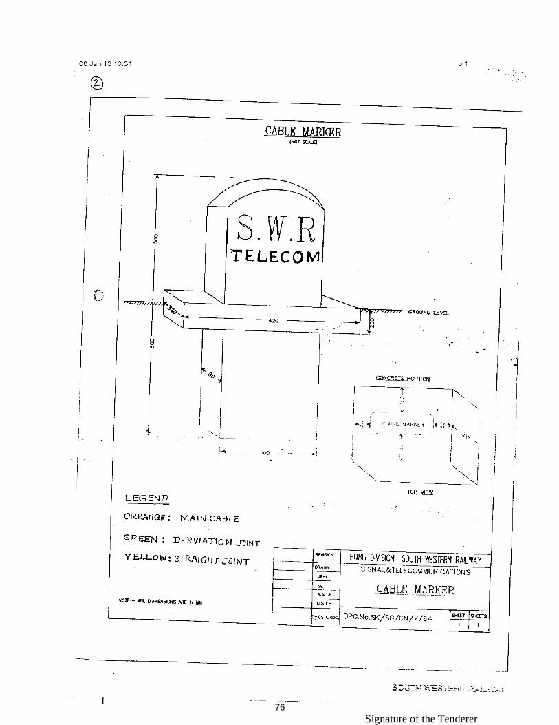
Signature of the Tenderer 76

Signature of the Tenderer 77

Signature of the Tenderer 78

Signature of the Tenderer 79

Signature of the Tenderer 80
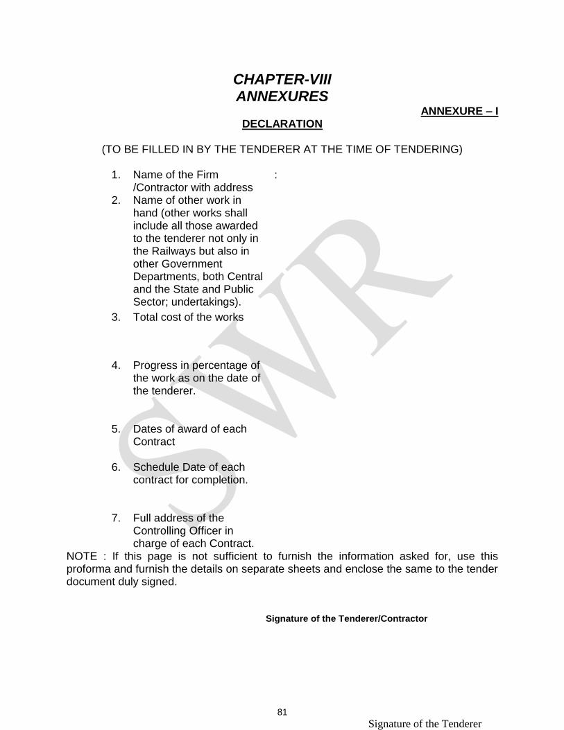
Signature of the Tenderer 81
CHAPTER-VIII ANNEXURES
ANNEXURE – I DECLARATION
(TO BE FILLED IN BY THE TENDERER AT THE TIME OF TENDERING)
1. Name of the Firm
/Contractor with address :
2. Name of other work in hand (other works shall include all those awarded to the tenderer not only in the Railways but also in other Government Departments, both Central and the State and Public Sector; undertakings).
3. Total cost of the works
4. Progress in percentage of the work as on the date of the tenderer.
5. Dates of award of each Contract
6. Schedule Date of each contract for completion.
7. Full address of the Controlling Officer in charge of each Contract.
NOTE : If this page is not sufficient to furnish the information asked for, use this proforma and furnish the details on separate sheets and enclose the same to the tender document duly signed. Signature of the Tenderer/Contractor

Signature of the Tenderer 82
S.W.RAILWAY
ANNEXURE - II
CERTIFICATE OF FAMILIARISATION
I/We hereby solemnly declare that I/We visited the site of above work and have familiarized myself/ourselves of the working conditions there in all respects and in particular the following :
1. Topography of the area
2. Soil conditions at the site of work.
3. Source and availability of construction materials.
4. Rate for Construction Materials.
5. Availability of local labour, both skilled and unskilled and
prevailing labour rates.
6. Availability of Water and Electricity.
7. The existing roads and access to the site of work.
8. Availability of space for putting labour camps, offices,
stores, godown, engineering yard etc.
Signature of the Tenderer/Contractor

Signature of the Tenderer 83
S.W.RAILWAY ANNEXURE - III
PERFORMANCE REPORT SHEET
(TO BE FILLED IN AND THE DOCUMENTS IN SUPPORT TO BE ATTACHED BY THE TENDERERS.)
1. Name and Address of the firm Individual/Proprietorship form
Partnership firm
Private Ltd./Public Ltd. Government undertaking 2. Financial capacity.
a) Audited annual turnover for last three years :- 2009-2010 2010-2011 2011-2012 b) Banker's Solvency Certificate from Scheduled Bank to be attached.
2. Detailed plants and machineries owned by the Tenderers and proof thereof.
Sl. Nos.
Name and make of Machinery with capacity
Date of purchase
Condition of machinery.
Place deployed presently
Whether the machine can be deployed immediately if contracts awarded ?

Signature of the Tenderer 84
4. EXPERIENCE OF TENDERERS :
2. Details of works executed and completed in the last 3 (three ) years (enclose).
Sl. No.
Name of work and contract number
Agreemental value
Final/ Completion value of the work
Name and address of employers
Completion time as per original Agreement
Actual time taken to be completed the works and reasons for delay if any.
Remarks
2. WORKS IN HAND :
Sl. Nos.
Name of the work and Contract No.
Agreemental value
Name & address of the employer
Completion time as per original agreement and whether extension given or not, if extended furnish the reasons for extension.
%age of progress of principal items of works
1. Particular of contracts terminated with risk and cost on the contractors if any :- 2. Details of Arbitration cases with Railway Administration and other organisation :-
NOTE : Documentary evidence regarding above declarations are to be attached by the tenderers and if it is found incorrect after verification of the declaration, their offer may be rejected without any further correspondence in this regard with the Tenderers.
Signature of Tenderer(s)/Contractor(s)

Signature of the Tenderer 85
ANNEXURE-IV
STRUCTURE AND ORGANISATION 1. Name of Tenderer
2. Nationality of Tenderer
3. Office Address
Telephone Number FAX Number
4. Year and Location of Establishment
5. The Tenderer is a) An individual b) A proprietary firm c) A firm in partnership d) A Limited company of
Corporation.
6 Attach the original chart showing the structure of the organization including the names of the Directors and position of Managers.
7. For how many years has your organization been in business of similar work under its present name ? What were your fields when your organisation was established ? Whether any new fields were added in your Organisation ? And if so, when ?
8. Number of years of experience.
a) As a Prime Contractor (Contractor shouldering major responsibility)
b) As Sub-contractor (Specify main contractor)
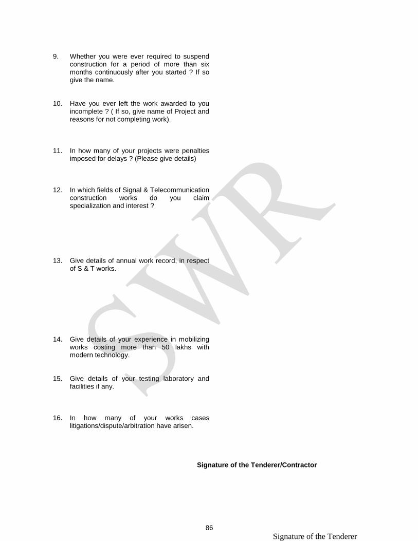
Signature of the Tenderer 86
9. Whether you were ever required to suspend
construction for a period of more than six months continuously after you started ? If so give the name.
10. Have you ever left the work awarded to you incomplete ? ( If so, give name of Project and reasons for not completing work).
11. In how many of your projects were penalties imposed for delays ? (Please give details)
12. In which fields of Signal & Telecommunication construction works do you claim specialization and interest ?
13. Give details of annual work record, in respect of S & T works.
14. Give details of your experience in mobilizing works costing more than 50 lakhs with modern technology.
15. Give details of your testing laboratory and facilities if any.
16. In how many of your works cases litigations/dispute/arbitration have arisen.
Signature of the Tenderer/Contractor

Signature of the Tenderer 87
ANNEXURE-V
PERSONNEL Give details of key Technical and Administrative Personnel (who could be assigned the work) in the following proforma : A. Details of the Board of Directors: 1) Name of the Directors :
2) Address
B. Key Technical and Administration/ Management Personnel and Consultants. 1) Individual's Name 2) Qualification
3) Present position 4) Professional experience and details of works carried. 5) Length of Service with the tenderer. C. Skilled and other labour :
1) Skilled Labour 2) Other Labour
Signature of the Tenderer/Contractor

Signature of the Tenderer 88
ANNEXURE-VI
FINANCIAL CONDITION
1. Name of firm
2. Name of Partner/Director
3. Capital
a) Authorized b) Issued and paid up
4. a) Details of the work successfully completed and Tenderer's performance record. b) Details of works on hand and Tenderer's performance record as on date of submission of Tender Document.
5. Furnish Balance Sheet and Profit and Loss statement with Auditor's Reports and Income Tax Assessment orders for last three years. It should interalia include the following information. i) Working capital ii) Foreign investment iii) Turnover for the year (furnish reference page number to Balance Sheet attached). Year 2009-2010 2010-2011 2011-2012 & Current year iv) Gross income in the year Year 2009-2010 2010-2011 2011-2012 & Current year

Signature of the Tenderer 89
v) Details of cash flow for three months at the peak construction period
6. What is the maximum annual turnover of the Project that you can handle ?
7. Have you ever been denied tendering facilities by any Government Department ?
8. List your sources of Finance
9. Certificate of Financial soundness by Bank
10. Name and address of Bank from whom reference can be obtained.
11. Have you ever been declared bankrupt ? (If yes, please give details).
12. B.G. limits from Nationalised Banks.
Signature of the Tenderer/Contractor
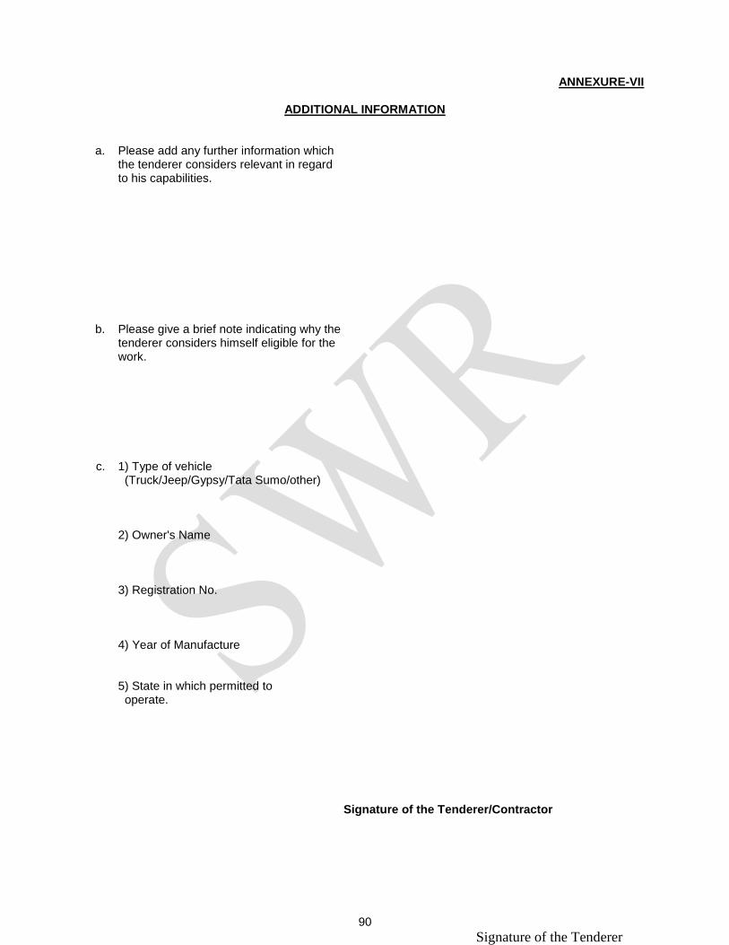
Signature of the Tenderer 90
ANNEXURE-VII
ADDITIONAL INFORMATION
a. Please add any further information which the tenderer considers relevant in regard to his capabilities.
b. Please give a brief note indicating why the tenderer considers himself eligible for the work.
c. 1) Type of vehicle (Truck/Jeep/Gypsy/Tata Sumo/other)
2) Owner's Name
3) Registration No.
4) Year of Manufacture
5) State in which permitted to operate.
Signature of the Tenderer/Contractor

Signature of the Tenderer 91
ANNEXURE-VIII
INDEMNITY BOND FOR SUPPLY OF MATERIALS TO THE CONTRACTOR We _________________________________________________ here by undertake that we hold that we hold in our custody for and on behalf of the President of India acting in the premises through the Deputy Chief Signal & Telecom Engineer, Project,/ South Western Railway, Hubli (herein after referred to as the purchaser) and as his property in trust of him all imported and indigenous materials which have been handed over to us against the contract for Shiting of Up & Down advanced starters outside of slip siding points and shifting of relays room at Ugarkhurd station on South Western Railway vide letter of acceptance ________________________________such as_____________________________________ handed over to us by the purchaser for the purpose of execution of the said contract, until such time the materials are duly erected or otherwise handed over to him. We shall entirely be responsible for the safe custody and protection of the said materials against all risk till they are duly delivered as erected equipment to the purchaser or as he may direct otherwise and shall indemnify the purchaser against any loss, damage or deterioration whatsoever in respect of the said materials while in our possession and against disposal of surplus materials. The said materials shall at all time opened to inspection by any officer authorized by the Deputy Chief Signal & Telecom Engineer, Project, South Western Railway, Hubli. Should any loss, damage or deterioration of materials occur or surplus materials disposed off and refund becomes due the purchaser shall be entitled to recover from us the full cost and compensation determined in terms of the contract for such loss, damage or deterioration, if any along with the amount to be refunded, without prejudice to any other remedies available to him, by deduction from any sum due/any sum which at any time hereafter becomes due to us under the said or any other contracts. In the event of any loss, damage or deterioration as aforesaid the assessment of such loss or damage and the assessment of such compensation therefore would be made by the President of India or his authorized nominee and the said assessments shall be final and binding upon us. Dated this the _______________________________ day _________2013
for & on behalf of the contractor.
Signature of Witnesses. 1. 2. Names of the witnesses in block letters. Address:- 1. 2.
Signature of the Tenderer

Signature of the Tenderer 92
CHAPTER-IX
TENDER SCHEDULE Name of the work: Shifting of Up and Down advanced starters outside of slip
siding points and shifting of Relays room at Ugarkhurd station
Schedule – ‘A’
Sl. No.
SOR No.
Description of item of work Qty Unit Rate Amount Inspn
1 1001 Excavation of cable trench in all kinds of soil except hard rocky areas including clearing of roots of trees, rocks, bushes etc. to a depth of 1.0 Mtrs and to a width of 0.3 Mtrs. Laying of cables is not included in this schedule.
2000 Mtrs 25.80 51600
2 1004 Excavation of cable trench across Metalised/Mecademised Roads to a width of 0.3 and a depth of 1m, laying of RCC pipes 100mm inner dia and 150mm outer dia with collars, for laying of cables, refilling the cable trench made across Metalised/Mecademised roads and re-surfacing to its original position. Laying of cables is not included in this schedule. [RCC pipe 100mm ID, 150mm OD, 2 mts. long with collar and all other miscellaneous materials required for the work shall be supplied by the Contractor].
100 Mtrs. 325.50 32550
3 1005 Removing/breaking of existing RCC slabs on the Passenger Platform, trenching to a depth of 0.6m to accommodate the additional cables, replacing the slabs removed after the cables are laid and re-plastering with cement mortar, refilling the trench by ramming and consolidating it as per the instructions of Railway Representative at site. Laying of cables is not included in this schedule. [Cement, river sand and all other miscellaneous materials required for the work shall be supplied by the Contractor].
100 Mtrs. 142.80 14280
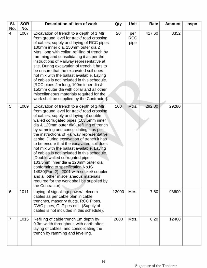
Signature of the Tenderer 93
Sl. No.
SOR No.
Description of item of work Qty Unit Rate Amount Inspn
4 1007 Excavation of trench to a depth of 1 Mtr. from ground level for track/ road crossing of cables, supply and laying of RCC pipes 100mm inner dia, 150mm outer dia 2 Mtrs. long with collar, refilling of trench by ramming and consolidating it as per the instructions of Railway representative at site. During excavation of trench it has to be ensure that the excavated soil does not mix with the ballast available. Laying of cables is not included in this schedule. [RCC pipes 2m long, 100m inner dia & 150mm outer dia with collar and all other miscellaneous materials required for the work shall be supplied by the Contractor].
20 per RCC pipe
417.60 8352
5 1009 Excavation of trench to a depth of 1 Mtr. from ground level for track/ road crossing of cables, supply and laying of double walled corrugated pipes (103.5mm inner dia & 120mm outer dia), refilling of trench by ramming and consolidating it as per the instructions of Railway representative at site. During excavation of trench it has to be ensure that the excavated soil does not mix with the ballast available. Laying of cables is not included in this schedule. [Double walled corrugated pipe - 103.5mm inner dia & 120mm outer dia conforming to specification No.IS 14930(Part 2) : 2001 with socket/ coupler and all other miscellaneous materials required for the work shall be supplied by the Contractor].
100 Mtrs. 292.80 29280
6 1011 Laying of signalling/ power/ telecom cables as per cable plan in cable trenches, masonry ducts, RCC Pipes, DWC pipes, GI Pipes etc. (Supply of cables is not included in this schedule).
12000 Mtrs. 7.80 93600
7 1015 Refilling of cable trench 1m depth by 0.3m width throughout, with earth after laying of cables, and consolidating the trench by ramming and levelling.
2000 Mtrs. 6.20 12400

Signature of the Tenderer 94
Sl. No.
SOR No.
Description of item of work Qty Unit Rate Amount Inspn
8 1013 Placing of one row of country bricks of size approximately 220mm x 100mm x 60mm breadthwise horizontally above the cables in 0.3m width trench. [Country bricks of size 220mm x 100mm x 60 mm (approximately) shall be supplied by the Contractor].
2000 Mtrs. 42.40 84800
9 1017 Supply of RCC cable markers as per drawing No. CSTE/CN/OFC/1. The lettering on the cable marker shall be "SIG" / "TELE" / "OFC" as per the instructions of Railway representative at site.
100 Nos. 144.60 14460
10 1018 Digging of pit to a depth of 800mm of size 300mmX300mm, casting of concrete foundation of size 300X300X300mm and Placing of RCC cable markers on top of the foundation and refilling the pit and consolidating it by ramming. The cable markers shall be provided at an interval of 20 Mtrs. within station limits and 50 Mtrs. outside station limits throughout the cable route, diversions and also at every track/road/crossing.
100 Nos. 113.20 11320
11 1019 Excavation of cable coil pit to a size of 1.0mx1.0m and depth of 1.0m for coiling the signal/power cable in rear of relay rooms/ AFTC huts, apparatus cases etc., as per the instructions of Railway representative at site. The work includes coiling the underground cables, and placing closely one layer of country bricks of size approx. 220mm x 100mm x 60mm breadthwise above the cables to cover all the cables in the cable pit, closing and consolidating the pit by ramming and levelling. [Country bricks of size 220mm x 100mm x 60mm (approximately) shall be supplied by the Contractor].
20 Nos. 389.70 7794

Signature of the Tenderer 95
Sl. No.
SOR No.
Description of item of work Qty Unit Rate Amount Inspn
12 2001 Excavation of pit, casting concrete foundation and erection of apparatus case full size as per Drg. No.SG/CN/02/6 and fixing of 2 Nos. of 'E' type locks, one for the front door and another for the back door, fixing of one hard wood shelf plank 37mm thick and painting the apparatus case inside and outside with one coat of red-oxide and two coats of aluminium paints. (Supply of apparatus case is not included in this schedule). [Foundation bolts & nuts, 'E' type locks, cement, river sand, stone jelly of size 20/25 mm, hardwood plank of 37mm thick, paints, varnish, fixing bolts & nuts and all other miscellaneous materials required for the work shall be supplied by the Contractor.]
4 Nos. 8367.00 33468
13 2002 Excavation of pit, casting concrete foundation and erection of apparatus case half size as per Drg, No.SG/CN/02/7, fixing one 'E' type lock for the front door and latching arrangement for the back door, and fixing of one hardwood shelf plank 37mm thick and painting the apparatus case inside and outside with one coat of red-oxide and two coats of aluminium paints.(Supply of apparatus case is not included in this schedule). [Foundation bolts and nuts, cement, 'E' type locks, river sand, stone jelly of size 20/25mm, 37mm hard wood planks, latching arrangements, paints, varnish, fixing bolts & nuts and all other misc. materials required for the work shall be supplied by the Contractor]
6 Nos. 5836.00 35016

Signature of the Tenderer 96
Sl. No.
SOR No.
Description of item of work Qty Unit Rate Amount Inspn
14 2009 Termination of new main/ tail cables on the existing terminals/ fuse blocks in apparatus cases/ battery boxes/ CT boxes/cable termination racks as per circuit diagram. The terminal particulars are to be repainted/corrected on the doors of apparatus cases/ battery boxes/ cable termination boxes and FTOT index board as instructed by Rly representative at site. This work includes closing the opening created for entry of new cables in the apparatus cases with masonry brick work and sealing the bottom of the apparatus cases/ cable termination racks with cable compound. [Paints, wire PVC 3/0.75mm and 16/0.2mm copper, sealing compound, bricks, cement, river sand and all other required miscellaneous materials shall be supplied by the contractor].
1000 Per Term- -inal
Block
29.70 29700
15 2013 Painting of existing apparatus cases without disturbing the terminations and equipments inside. The work involves scraping of old paint, applying one coat of Red oxide and two coats of Aluminium paint on the inside and outside the apparatus cases, as instructed by Railway representative at site. [Aluminium paint, red-oxide and all other miscellaneous materials required for the work shall be supplied by the Contractor].
a. Painting of existing apparatus case - Full size
12 Nos. 916.00 10992
b. Painting of existing apparatus case - Half size
8 Nos. 871.00 6968
16 2029 Manufacture and supply of Enameled Number plates with fixing arrangements and fixing them on the existing Signals as per the instructions of Railway representative at site.[Enameled number plates with fixing arrangements with bolts and nuts shall be supplied by the Contractor].
20 Nos. 266.20 5324

Signature of the Tenderer 97
Sl. No.
SOR No.
Description of item of work Qty Unit Rate Amount Inspn
17 2010 Termination of main, tail, Signalling and power cables and internal wiring on terminal/ fuse blocks in new apparatus cases, cable termination boxes and in gate lodges excluding cable termination rack at relay room. The work includes fixing of all new cables by teakwood clamp on teakwood base plank, fixing of Phynolic synthetic industrial fibre base fine weave cotton fibre board 6mm thick for terminal board to suit each apparatus case, varnishing all teakwood items, fixing of terminals/ fuse blocks on the terminal board, drilling of necessary holes, termination of cables, wiring, identification of cables using aluminium tags with letters punched neatly, as per approved circuit diagram and cable plan, painting of particulars on sleeves and also on the inner side of the doors of apparatus cases. After terminations are over, the side openings of apparatus case foundation shall be closed with brick work, cement plastered, the inter-space filled with river sand upto base level and the bottom surface shall be sealed with sealing compound. (Supply of PBT terminals and Fuse blocks is not covered in this schedule). [Cement, teakwood cable clamp 50mm x 50mm, base planks 100mm x 25mm, Phynolic synthetic industrial fibre base fine weave cotton fibre sheet - 6mm thick to IS specification 2036 - 1995 - Type F5, PVC/Nylon sleeves, varnish, paints, bolts, nuts and washers, Non-deteriorating type of fuses of various capacities, Aluminium cable tags, sealing compound, country bricks 220mm x 100mm x 60mm, copper bus bars, brass screw, river sand, wire PVC3/0.75mm copper and other miscellaneous materials shall be supplied by the Contractor].
a. Termination on 25/60mm PBT terminals (new location)(Phynolic sheet)
500 Term-inal
Block
74.10 37050

Signature of the Tenderer 98
Sl. No.
SOR No.
Description of item of work Qty Unit Rate Amount Inspn
b. Termination on PBT fuse block (new location) (Phynolic sheet)
150 Fuse Block
98.10 14715
18 2011 Termination of main, tail, Signalling and power cables and internal wiring by fixing additional terminals/ fuse blocks on the existing terminal boards of apparatus cases, cable termination boxes etc. The work includes fixing of all new cables by teakwood clamp on teakwood base plank, varnishing all teakwood items, fixing of terminals/ fuse blocks, on the existing terminal boards, drilling of necessary holes, termination of cables, wiring, identification of cables using aluminium tags with letters punched neatly, as per approved circuit diagram and cable plan, painting of particulars on sleeves and also on the inner side of the doors of apparatus cases. After terminations are over, the side openings of apparatus case foundation shall be closed with brick work, cement plastered, the inter-space filled with river sand upto base level and the bottom surface shall be sealed with sealing compound.
(Supply of PBT terminals and Fuse blocks is not covered in this schedule). [Cement, teakwood cable clamp 50mm x 50mm, base planks 100mm x 25mm, PVC/Nylon sleeves, varnish, paints, bolts, nuts and washers, Non-deteriorating type of fuses of various capacities, Aluminium cable tags, sealing compound, country bricks 220mm x 100mm x 60mm, copper bus bars, brass screw, river sand, wire PVC3/0.75mm copper and other miscellaneous materials shall be supplied by the Contractor].
a. Termination of cables on 25/60mm PBT terminals (existing location)
1000 Terminal
Block
62.50 62500
b. Termination of cables on PBT fuse block (existing location)
25 Fuse Block
86.60 2165

Signature of the Tenderer 99
Sl. No.
SOR No.
Description of item of work Qty Unit Rate Amount Inspn
19 2012 Manufacture and supply of M.S. relay frames of suitable size to hold upto 4/ 8/ 12/ 20 relays as required by Railways and fixing them in apparatus cases for all types of signal control circuits, LC gate control circuit, lever lock control circuits and Point control circuits, fixing of plug boards, relays, resistors and electrolytic condensors on Phynolic synthetic industrial fibre base fine weave cotton fibre sheet - 6mm thick to IS specification 2036 - 1995 - Type F5, wiring and termination as per approved circuit diagram and painting the particulars.
(Supply of all types of relays, plug boards, connectors, retaining clips and 50 way terminal boards is not covered in this schedule). [Wire PVC copper, 3/0.75mm and 16/0.2mm copper, Phynolic synthetic industrial fibre base fine weave cotton fibre sheet - 6mm thick to IS specification 2036 - 1995 - Type F5, for fixing resistors and condensors, MS flats 25mm x 6mm brass bolts and nuts, paints, soldering materials, resistors, condensors and all other miscellaneous materials required for the work shall be supplied by the contractor.)
a. Wiring of Signal/ point/ LC control circuit (upto 4 relays)
10 Set 2104.00 21040
b. Wiring of Signal/ Point/ LC control circuit (upto 8 relays)
2 Set 3647.00 7294
20 2018 Excavation of pit, casting concrete foundation as per Drg.No.SG/CN/02/9 using metallic templates, for erection of colour light signals upto 4 aspects. [Foundation bolts, cement, river sand, stone jelly of size 20/25mm dia and all other miscellaneous materials required for the work to be supplied by Contractor].
6 Nos. 4455.00 26730

Signature of the Tenderer 100
Sl. No.
SOR No.
Description of item of work Qty Unit Rate Amount Inspn
21 2019 Erection of surface base, signal pole, mounting of colour light signal upto 4 aspects complete on Signal pole/ Off-set bracket, (for LED/ filament bulbs) with lenses, triple pole lamp holder, filament switching units, CLS transformer, current regulators (whichever is applicable), fixing of ladder with platform complete and concreting of ladder shoe, fixing of number plates, marker board, lens guard, termination of tail cables, wiring of signal unit with PVC wire 3/0.75mm copper, provision of EWS locks, and painting of one coat of red oxide and two coats of aluminium/ enamel paints. When the aspect is fixed on Offset bracket using 'U' bolts and nuts a through bolts shall be provided by drilling a hole in the signal pole to prevent the offset bracket from sliding down.
6 Nos. 4066.00 24396
(Supply of surface base, Off set bracket, CLS pole, CLS aspect complete, ladder with shoes and platform, LED aspects, current regulators is not covered in this schedule). ['U' bolts and nuts, through bolts and nuts, cement, stone jelly 20/25mm dia, river sand, Signal Collar Rings, wire PVC 3/0.75mm copper, lens-guard, all fixing bolts and nuts, lead wool, paints PVC/Nylon sleeves, enameled number plates. enameled marker boards, EWS locks, and all other miscellaneous materials for the work shall be supplied by the Contractor].

Signature of the Tenderer 101
Sl. No.
SOR No.
Description of item of work Qty Unit Rate Amount Inspn
22 2024 Fixing of junction type route indicators - 1 way to 5 way - complete/ fixing of additional limb to the existing route indicators, termination of tail cables, wiring as per approved circuits diagram using wire PVC 3/0.75mm copper, provision of required No of EWS locks, wire mesh, and painting. (Supply of junction type Route Indicators - complete, and additional limb is not covered in this schedule). [3/0.75mm wire PVC, fixing bolts and nuts, EWS locks, wire mesh, PVC/Nylon sleeves, paints and all other miscellaneous materials shall be supplied by the Contractor].
a. Fixing, wiring of direction type route indicator - 1 way
2 Nos. 1186.00 2372
23 2025 Fixing of Offset brackets using 'U' bolts and nuts, erection of Calling On Signals/ 'A' marker lights, termination of tail cables and wiring using wire PVC 3/0.75mm copper, provision of EWS lock, number plates/ marker boards and painting. The work also includes drilling suitable holes on the CLS post and provision of a through bolt with nut to prevent the Off-set bracket from slipping down. (Supply of Calling On Signal/ 'A' marker light and Off set brackets is not covered in this schedule). ['U' bolts and nuts, through bolts with nut, wire PVC 3/0.75mm copper, EWS lock, Enameled number plates, wire mesh, PVC/Nylon sleeves, paints and all other miscellaneous materials shall be supplied by the contractor].
2 Nos. 1115.00 2230

Signature of the Tenderer 102
Sl. No.
SOR No.
Description of item of work Qty Unit Rate Amount Inspn
24 2032 Provision of DC double rail track circuit to suit Non-RE Standard as per approved signalling plan using Plugin type track relays. This work includes provision of double bonding, and parallel jumpering, provision of bond wire clips, provision of track lead connections with 8 SWG GI soft wire with necessary arrangements for fixing lead wires to the sleeper, provision of TLD boxes 2 Nos. at Relay end, 2 Nos. at Feed end and 2 Nos for parallel jumpering for each Track Circuit, and termination of jumpers and tail cables in track lead junction boxes, installation of relays, track feed battery chargers to charge upto 4 cells, track feed resistance, and charged secondary cells - 80 AH capacity in apparatus cases and wiring with wire PVC 3/0.75mm copper. The work also includes painting of track circuit No. with Feed end/ Relay end details on the TLD boxes. The work also includes provision of insulations for gauge tie plates and nose crossing plates. Provision of rail joint insulation is not covered in this schedule.
(Supply of track relays, secondary cells (2V - 80AH), TLD boxes with stumps is not covered in this schedule). [Track feed battery charger to charge upto 4 cells, track feed resistance, Gauge tie plate and nose crossing plate insulations, PVC/Nylon bushes for TLD boxes, PVC sleeves, all types of fixing bolts and nuts with spring and flat washers, teakwood stand for fixing track feed resistance, GI bond wire 8 SWG, Channel bond pins, bond wire clips, paints and all other miscellaneous materials shall be supplied by the contractor. Secondary cells-80 AH capacity shall be charged by the contractor through reputed charging agencies].
a. Provision of track circuit in Non-RE area (point zone)
2 Nos. 6124.00 12248

Signature of the Tenderer 103
Sl. No.
SOR No.
Description of item of work Qty Unit Rate Amount Inspn
b. Provision of track circuit in Non-RE area (other than point zone)
6 Nos. 5082.00 30492
25 2035 Supply and provision of Rail Joint Insulations. This work includes milling of fish plates, provision of rail joint insulation with MS backing plates etc., and insulating the joints as per Railway standard. (Supply of Un-milled fish plates, fish bolts and nuts is not covered in this schedule). [Rail joint insulation complete set with MS backing plates shall be supplied by the Contractor].
20 Set. 801.80 16036
26 2039 Supply of Colour light Signal pole 140mm dia, 4.6m/ 3.6m tall with necessary inspection as per specification/ drawing/ description enclosed in this document.
a. Supply of colour light Signal pole(4.6m) 4 Nos. 2860.00 11440
b. Supply of colour light Signal pole(3.6m) 2 Nos. 2059.00 4118
27 2040 Supply of surface base to suit CLS Signal pole 140mm dia with necessary inspection as per specification/ drawing/ description enclosed in this document.
6 Nos. 2746.00 16476
28 2041 Supply of ladder with platform and shoes to suit CLS pole 4.6m/ 3.6m tall, with necessary inspection as per specification/ drawing/ description enclosed in this document.
a. Supply of ladder with platform and shoes for 4.6m CLS pole
4 Nos. 2631.00 10524
b. Supply of ladder with platform and shoes for 3.6m CLS pole
2 Nos. 2517.00 5034
29 2044 Supply of Colour Light Signal Multi Unit type - complete for 4/ 3/ 2 aspect with mounting socket, with necessary inspection as per specification/ drawing/ description enclosed in this document.
b. Supply of colour light Signal unit - 3 aspect
4 Nos. 8580.00 34320
c. Supply of colour light Signal unit - 2 aspect
2 Nos. 6864.00 13728

Signature of the Tenderer 104
Sl. No.
SOR No.
Description of item of work Qty Unit Rate Amount Inspn
30 2045 Supply of Junction type route indicator – 5 unit arm – 1/ 2/ 3/ 4/ 5 way with mounting sockets, Lamp holder for SL 33 lamps and Lenses for route indicators with necessary inspection as per specification/ drawing/ description enclosed in this document.
a. Supply of Junction type route indicator - 1 way
2 Nos. 10296.00 20592
31 2046 Supply of Calling On Signal / 'A' marker light - complete with lens and holder with necessary inspection as per specification/ drawing/ description enclosed in this document.
a. Supply of Calling On Signal 2 Nos. 1716.00 3432
32 2047 Supply of Off-set brackets - large/ small made of cast iron with necessary inspection as per specification/ drawing/ description enclosed in this document.
a. Supply of Off-set bracket (large) 2 Nos. 1716.00 3432
33 2049 Supply of Track lead junction box Fiber moulded with pipes for cables and stump, and terminals fixed in it.
30 Sets 915.00 27450
34 2053 Supply of electronic time delay units (120/60 secs) with plug boards, connectors and retaining clips with necessary inspection as per specification/ drawing/ description enclosed in this document.
16 Nos. 2422.00 38752
35 2054 Supply of apparatus cases (full/ half/ quarter size) to suit Southern Railway standard with necessary inspection as per specification/ drawing/ description enclosed in this document:
a. Supply of apparatus case - Full size 4 Nos. 8115.00 32460
b. Supply of apparatus case - Half size 4 Nos. 5172.00 20688
c. Supply of apparatus case - Quarter size
2 Nos. 3543.00 7086

Signature of the Tenderer 105
Sl. No.
SOR No.
Description of item of work Qty Unit Rate Amount Inspn
36 2060 Supply of Electric key transmitter - rotary type of required ward Nos. with keys, with necessary inspection as per specification/ drawing/ description enclosed in this document.
10 Nos. 4004.00 40040
37 3001 Concreting and erection of cable termination rack 500/210/140 Terminals capacity on teakwood base frame of size 50mmx150mm of suitable length and width with rectangular slot in the center for taking in the cables, and painting as per standard practice. (Supply of cable termination racks is not included in this schedule). On bolts and nuts with washers, cement, sand, stone jelly, teak wood base frame 50mmx150mm of suitable length and breadth, paints and all other miscellaneous materials required for the work shall be supplied by the contractor]
b. Concreting and erection of cable termination rack - 500 terminal capacity
2 Nos. 6660.00 13320
38 3003 Concreting and erection of Relay racks- 68/56 relay capacity using 'J' type bolts and painting of relay rack as per the instructions of Railway representative at site. (Supply of relay rack is mot covered in this schedule). ['J' type bolts and nuts with washers, nylon bushes, concreting materials, paint and all other miscellaneous materials required for the work shall be supplied by the Contractor].
b. Concreting and erection of Relay Rack - 56 relay capacity
6 Nos. 1350.20 8101
39 3007 Erection and concreting of SM's control panel on teakwood base frame 50mm x 150mm of suitable length and breadth, varnishing, termination of cables and wiring of knobs, buttons, indications, counters, etc., as per the approved circuit diagram with wire PVC 16/0.2mm copper.

Signature of the Tenderer 106
Sl. No.
SOR No.
Description of item of work Qty Unit Rate Amount Inspn
The work includes manufacture and provision of extension tables using hardwood with decolum finish, fixing of one voltmeter, required No. of buzzers and wiring. The termination particulars shall be painted on the back doors of the panel. (Supply of SM's control panel is not included in the schedule). [Foundation bolts and nuts with washers, concreting materials, wire PVC 16/0.2mm copper, 50mmx150mm teakwood base frame, hardwood extension table with decolum finish using 25mm thick planks and 75mmx75mm reapers, soldering materials, buzzers to work on 24VDC, one voltmeter 0-300V AC and all other consumable materials required shall be supplied by the Contractor].
a. Erection, concreting and wiring of SM's control panel (upto 5 roads)
1 Nos. 20279.00 20279
40 3008 Provision of Interconnections between relay racks, cable termination racks, SM's control panel, battery room, power room, termination and wiring. The work involves laying of underground cables in the duct as wells as with clamping arrangements on the walls, supply and fixing of aluminium ladders and supports with 3mm thick Phynolic sheet for running the cables in the relay room. Interconnection shall be carried out with signalling multi core cable (skinned/ unskinned) and power cables as per the instructions of Railway representative at site. The work also include termination of the interconnection cables on 50 way terminals in the relay rack/ control panel, cable termination rack etc. After the interconnection cables are laid, the ducts shall be filled with river sand and closed. Wherever required the cables shall be taken to other floors in the building by clamping them on MS angles and flats grouted on the walls.

Signature of the Tenderer 107
Sl. No.
SOR No.
Description of item of work Qty Unit Rate Amount Inspn
(Supply of interconnection cables is not included in this schedule). [2BA terminals, Aluminium ladder arrangements using 37mmx37mmx5mm aluminium angles and 25mmx6mm aluminium flats, aluminium supports, Phynolic sheet - 3mm thick for bottom of aluminium ladders, MS angles and flats, bolts and nuts, concreting materials, and all other materials required for the work shall be supplied by the contractor].
a. Provision of interconnection at stations (upto 5 roads).
1 LS 34268.00 34268
41 3011 Provision of signalling arrangement during Non-Interlocked working of Signals and Points, such as erection and wiring of temporary relay racks and wiring of relays, SM's slide instruments, wiring alterations in the cable termination rack, apparatus cases, signals, Control panel etc, as per the instructions of Railway representative at site. This work includes temporary provision of PA system and Magneto telephone communication at places required which will be returned to the Contractor after the completion of NI working. (Supply of relay rack, relays, and SM slide instrument is not included in this schedule). [All other miscellaneous materials required for the work shall be supplied by the Contractor].
1 LS 16635.00 16635
42 3014 Supply and provision of Rubber mat of not less than 6mm thick and with an insulation to withstand 650VAC, on the floor at places as indicated by railway representative at site.
400 Sq. ft 73.40 29360

Signature of the Tenderer 108
Sl. No.
SOR No.
Description of item of work Qty Unit Rate Amount Inspn
43 3028 Installation of single line push button token less block instruments on teakwood base frame. The work involves termination of cables on the test panel, block wiring including duplicating switch for "Train Arrival" and interconnection between test panel and block instrument by underground signalling cable and painting the instrument in consultation with Railway representative at site. (Supply of block instrument and underground cables is not included in this schedule). [Wire PVC 16/0.2mm copper, 3/0.75mm, Teak Wood base frame of size 50mmx 150mm, foundation bolts, paint, concreting materials and all other miscellaneous materials required for the work shall be supplied by the contractor].
2 Nos. 7522.00 15044
44 4012 Supply and installation of teakwood glass fronted box of size 300mm x 600mm x 75mm with hooks to keep various keys with description engraved on the tags. [TW Glass fronted box of size 300mmx600mmx 75mm with built in lock, hooks, engraved tags and all other miscellaneous materials required for the work shall be supplied by the Contractor].
2 Nos. 2748.00 5496
45 4014 Fixing of EKT instrument with (or) without crank handle or on suitable fixtures at station/apparatus case, provision of economiser push switch with locking facility, wiring with wire PVC 16/0.2mm copper, termination of cables and jumper wires on PBT terminal in a teakwood terminal box covered with decolum along with locking facility and painting.(Supply of electric key transmitter and crank handles is not covered in this schedule).[wire PVC 16/0.2mm copper, wire wound resistance, decolum covered terminal box with locking facility by using 25mm thick teakwood, bolts and nuts, paints, push switches, padlocks and other miscellaneous materials required for this work shall be supplied by the contractor].
10 Nos. 2463.00 24630

Signature of the Tenderer 109
Sl. No.
SOR No.
Description of item of work Qty Unit Rate Amount Inspn
46 4019 Supply and installation of magneto telephone handle type along with Ni-cad power pack 4V-2.2AH with charger to work on 110VAC, at the station house, LC Gate and top points. For telephones connected in pair with Signal Post Telephones, the work involves provision of teakwood box with locking facility for fixing the magneto telephone and provision of buzzers to work on 24VDC. [Magneto telephone handle type with Ni-cad power pack 4V-2.2AH with charger to work on 110VAC, wire PVC 16/0.2mm copper, and all other miscellaneous materials shall be supplied by Contractor.
a. Supply & wiring of magneto telephone at station/ LC gates/ apparatus cases
4 Nos. 5409.00 21636
47 4021 Installation and wiring of existing Way station equipment DTMF and control telephones. The work involves fixing the released way station equipment on the wall at an appropriate place in consultation with Railway representative at site, wiring and interconnecting the same with test panel, control telephones and batteries. (Supply of way station equipment, control telephones and batteries is not included in this schedule). [Wire PVC 3/0.75mm & 16/0.2mm copper, MS clamps for fixing arrangements, PVC tubes 25mm dia for interconnections and all other miscellaneous items required for the work shall be supplied by the Contractor].
1 Set. 3656.00 3656

Signature of the Tenderer 110
Sl. No.
SOR No.
Description of item of work Qty Unit Rate Amount Inspn
48 4022 Supply and installation of Signal post telephone with facility of paging and talk-back including voice communication equipment with suitable switching arrangement at the Signal post and at SM's room as per specification enclosed in this document. This includes drawal of tail cable through GI pipe 25mm dia and 2 mtrs long duly clamped to Signal post with bend as required at site, termination of tail cable at one end in the apparatus case and other end in the console. In the SM's room, console shall be fixed on a table top. The wiring shall be done using wire PVC 16/0.2mm copper. [Talk-back equipment complete including housing box, wire PVC 16/0.20mm and all other miscellaneous materials required for the work shall be supplied by the Contractor].
2 Set. 8211.00 16422
49 4023 Excavation of pit and construction of masonry platform as per drawing No. SG/CN/02/12 with bricks of size 200mmx100mmx60mm (app) at the foot of signal post telephones as per the instructions of Railway representative at site.[Country bricks of size 220mmx100mmx60mm (app), cement, river sand and all other miscellaneous materials required for the work shall be supplied by the Contractor].
2 Nos. 2314.00 4628
50 4026 Supply and installation of yard layout diagram board in the station master's room. The board shall be made of Phynolic synthetic industrial fibre base fine weave cotton fibre board (matt finish) 6mm thick size 1800mm X 1200mm with aluminium channel frame. The yard layout shall be neatly painted and fixed as instructed by Railway representative at site. [All materials required for the work shall be supplied by the Contractor].
1 Nos. 7238.00 7238

Signature of the Tenderer 111
Sl. No.
SOR No.
Description of item of work Qty Unit Rate Amount Inspn
51 4027 Provision of firefighting equipments. The work involves supply and installation of the following equipments at places as instructed by Rly representative at site. a. Photo Electric Smoke Detector (similar to Vigilant Model : DS-7001 of M/.s. Naveen Alarm Systems) - 8 Nos. b. Two Zone Fire alarm panel (similar to Model: NSB 400 of M/s. Naveen Alarm Systems) - 1 No. c. ABC 5 Kg. capacity stored pressure fire extinguisher - 2 Nos. d. Hooter to work on 24 VDC - 1 No. Wiring shall be done using underground cable as per the instructions of Railway representative at site. (Supply of underground cable is not covered in this schedule). [Photo electric smoke detector, 2 zone fire Alarm panel, fire extinguisher, hooter and all other misc. materials required for the work shall be supplied by the Contractor].
2 Set. 28367.00 56734
52 4030 Submission of all relevant final `As-mades' of circuit diagrams, contact analysis charts, termination particulars of apparatus cases and cable termination rack, power supply arrangements, relay index board, cable plans, cable route plans, red boundary plans and all other particulars covered under various schedules. All 'As mades' shall be prepared by the Contractor in AUTOCAD 2000 and submitted in CDs. One copy of the 'As mades' shall be submitted before Bell Testing the circuits. The final negatives shall be made in R.P film. All 'As mades' except cable plan and cable route plan shall be prepared in A3 size. On approval the contractor shall submit along with the negatives, 8 copies in each, duly making booklet neatly bound. Out of 8 sets, 2 sets of drawings and other plans shall be kept in thick plastic cover with hanger arrangements for each cover (2 sheets back to back in one plastic cover) and handed over to Railways.
100 per 'A3' size
sheet
167.80 16780
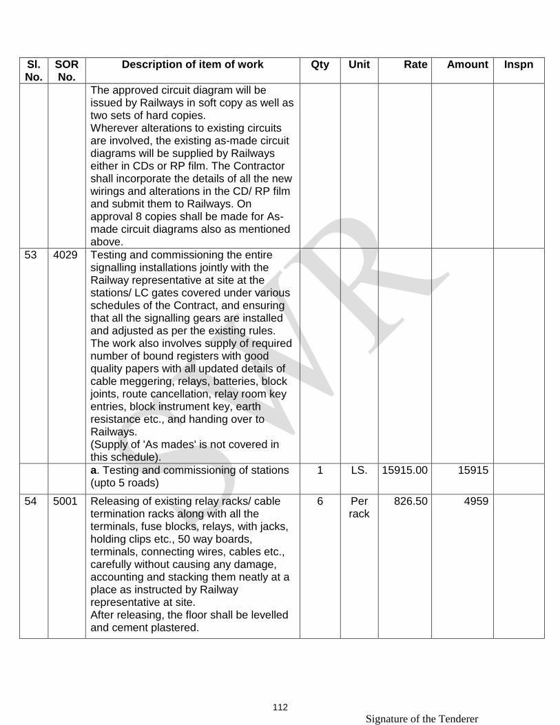
Signature of the Tenderer 112
Sl. No.
SOR No.
Description of item of work Qty Unit Rate Amount Inspn
The approved circuit diagram will be issued by Railways in soft copy as well as two sets of hard copies. Wherever alterations to existing circuits are involved, the existing as-made circuit diagrams will be supplied by Railways either in CDs or RP film. The Contractor shall incorporate the details of all the new wirings and alterations in the CD/ RP film and submit them to Railways. On approval 8 copies shall be made for As-made circuit diagrams also as mentioned above.
53 4029 Testing and commissioning the entire signalling installations jointly with the Railway representative at site at the stations/ LC gates covered under various schedules of the Contract, and ensuring that all the signalling gears are installed and adjusted as per the existing rules. The work also involves supply of required number of bound registers with good quality papers with all updated details of cable meggering, relays, batteries, block joints, route cancellation, relay room key entries, block instrument key, earth resistance etc., and handing over to Railways. (Supply of 'As mades' is not covered in this schedule).
a. Testing and commissioning of stations (upto 5 roads)
1 LS. 15915.00 15915
54 5001 Releasing of existing relay racks/ cable termination racks along with all the terminals, fuse blocks, relays, with jacks, holding clips etc., 50 way boards, terminals, connecting wires, cables etc., carefully without causing any damage, accounting and stacking them neatly at a place as instructed by Railway representative at site. After releasing, the floor shall be levelled and cement plastered.
6 Per rack
826.50 4959

Signature of the Tenderer 113
Sl. No.
SOR No.
Description of item of work Qty Unit Rate Amount Inspn
55 5008 Releasing of existing apparatus cases (Full/ Half/ Quarter size) without damage after releasing the shelf planks, terminal blocks, Fuse blocks, terminal boards, Relays of all types EKTs, Secondary Cells, power equipments, 'E' type locks, etc., and breaking the concrete foundation. After releasing, the resultant pits are to be closed and consolidated by ramming and levelling. The released materials shall be accounted and stacked at a place as instructed by Railway representative at site.
6 Nos. 1202.50 7215
56 5011 Releasing of existing SM's control panel including base plank, and other gadgets connected very carefully without causing any damage to the panel, accounting and stacking them neatly at a place as instructed by Railway representative at site. The resultant pit in the flooring shall be removed of all cable bits, levelled and cement plastered.
1 Set 2180.00 2180
57 5012 Dismantling and releasing of existing Colour light Signals complete (upto 4 aspects) with or without Route Indicators, calling on signals, shunt signals etc., carefully without any damage to the gadgets, accounting and stacking them neatly at a place as instructed by Railway representative at site. The work includes breaking the concrete foundation, closing the resultant pit and resurfacing it by ramming and levelling.
6 Nos. 1233.00 7398
58 5016 Releasing of existing Block Instruments (all types), Block counters, batteries, block filter, block bell equipment etc., carefully without any damage, accounting and stacking them neatly at a place as instructed by Railway representative at site.
2 Nos. 716.50 1433

Signature of the Tenderer 114
Sl. No.
SOR No.
Description of item of work Qty Unit Rate Amount Inspn
59 5017 Releasing of existing block/ control wiring along with DPDT switches, Lightning dischargers, wires, and boards including the junction box in station buildings, accounting and stacking them neatly at a place as instructed by Railway representative at site.
1 Set 1497.00 1497
60 5026 Releasing of existing TLD boxes with stumps and terminals after releasing all the bond wires. The released materials shall be accounted and stacked neatly at a place as instructed by Railway representative at site.
12 Nos. 64.50 774
61 5027 Releasing of all power equipments including equipment stands, terminal boards, power panel etc., in the power room carefully without causing any damage to the equipments after disconnecting all the supply wires. The released equipments shall be accounted and stacked at a place as instructed by Railway representative at site. After releasing any holes in the walls/ flooring shall be filled with cement mortar and plastered.
1 Set 5111.00 5111
62 5028 Releasing of existing control equipments - complete including way station equipments, telephones, power supply foe way station equipment and telephones, along with all wiring, accounting and stacking them neatly at a place as instructed by Railway representative at site.
1 Set. 2428.00 2428
63 5029 Transportation of Signalling materials by road as per the instructions of Railway representative at site. The work also includes loading and unloading of the materials.
30000 Per ton. Km.
2.37 71100
Total 1444981

Signature of the Tenderer 115

116
SCHEDULE – ‘B’
Sl. No.
Description of item of work Qty Unit Rate in Figures
Rate in Words Inspection
1 Fabrication & Supply of MS frames to suit Q-series relay to accommodate six nos. in each set as per Drg No. B/SG/CON/ST/ Misc.9.98 duly drilling holes for relay bases (All the material such as frame, bolts, nuts washers, etc. are to be supplied by the contractor)
100 Nos Consignee
2 Supply of track feed regulating resistance disk type 0 to 30 ohms as per IRS Spec. No. SA 20161/66/M
12 Nos. Consignee
3 Supply and fixing of teak wood reapers of size 50mm x 50mm x 940mm in full location box after applying two coats of wood primers and clamping the cables.
4 Per Reap
er
Consignee
4 Supply and fixing of teak wood reapers of size 50mm x 50mm x 470mm in half location box after applying two coats of wood primers and clamping the cables.
6 Per Reap
er
Consignee

Signature of the Tenderer 117
Sl. No.
Description of item of work Qty Unit Rate in Figures
Rate in Words Inspection
5 Supply of 200 way unwired Tag block
5 Nos Consignee
6 Supply of Hylam sheet of size 2400mmX1200mmX6mm
2 Nos. Consignee
7 Supply of Hylam sheet 3mm thick and size 2400mmX600mm of colour approved by the site-in-charge
3 Nos. Consignee
8 Supply and fixing of digital voltmeter and ammeters of MECO make or equivalent for power panel and wiring same carefully.
6 Nos. Consignee
9 Supply of Electrolytic Condensers 50V/470mFd
50 Nos Consignee
10 Supply of Electrolytic Condensers 50V/1000mFd
60 Nos Consignee
11 Supply of Wire wound Resistance 10 W & 100/150/500/2200 Ohms
50 Nos Consignee
12 Supply of Diode BY 127/IN5408
50 Nos Consignee

Signature of the Tenderer 118
Sl. No.
Description of item of work Qty Unit Rate in Figures
Rate in Words Inspection
13 Supply of LED holders with LED's of size 5 mm and 1.0 Watt resistance with different values
150 Nos Consignee
14 Design of As-planned drawing for 3 Road Stations
1 Set
15 Supply of basic material to construct a maintenance Free Ring Earth with four pits for achieving less than one ohm as per RDSO/SPN/197/2008 consists of a) Copper bonded steel electrodes of 3.0 m long, 17mm dia with copper bonding of min 250 micron thick and UL listed and marked -- 4 Nos b) Earth enhancement compound of RDSO approved brand supplied in sealed bags of min 10kgs -- 15 Nos c) Copper strip of 150 x 25 x 6mm to terminate Earth Rod -- 1 No d) Copper Strip of 300x25x6mm (MEEB)-1No e) Copper Strip of 150x25x6mm (SEEB)-2Nos All the other materials including inter connecting wires etc., to be supplied by the contractor.
1 Sets RITES

Signature of the Tenderer 119
Sl. No.
Description of item of work Qty Unit Rate in Figures
Rate in Words Inspection
16 Supply of basic Materials to construct unit maintenance free earth as per RDSO specs. No RDSO/SPN/197/2008 or latest and confirming to RDSO Drg. No SDO/RDSO/E&B/001 dtd 19.09.2008.It consists of following:
6 Set RITES
i) Copper bonded steel electrode of 3.0m long 17.2 mm dia with copper bonding thickness of minimum macrons and UL listed and marked 1 No.
ii) Earth enhancement material supplied in sealed bags of minimum 10Kg = 3 Nos.
iii) Copper strip of 150x25x6mm to terminate earth rod=1no.
iv) Copper strip of 300x25x6mm (MEEB)=1no.
v) Copper strip of 150x25x6mm (SEEB)=1no.
vi) Supply of 35sq mm multi-stranded single core PVC insulated copper cable as per IS: 694 for connecting main earth electrode to MEEB in the equipment room in duplicate.

Signature of the Tenderer 120
Sl. No.
Description of item of work Qty Unit Rate in Figures
Rate in Words Inspection
vii) Supply of 16sq mm multi-stranded single core PVC insulated copper cable as per IS:694 for connecting MEEB to SEEB and SPD to MEEB
viii) Supply of 10sq mm multi-stranded single core PVC insulated copper cable as per IS:694 for connecting various equipment to SEEB
17 Supply of 24 Volts impulse counters 6 Digits (without reset button)
6 No Consignee
18 Digging of cable trench to a depth of not less than 30 cms in rocky terrain, concreting the trench with 150 mm thick concrete in the ratio of 1:2:4 and back filling with excavated soil. (Cement, sand & metal are to be supplied by the Contractor) This is applicable for concrete platforms/Metal tar/Cement roads
500 Mtrs

Signature of the Tenderer 121
Sl. No.
Description of item of work Qty Unit Rate in Figures
Rate in Words Inspection
19 Installation, testing & commissioning of Data-logger 512 digital 32 analog inputs at site & connecting to network. Correspondence between Relay-room to Data-logger shall be certified by representative of the OEM.
1 Nos.
20 Supply & fixing of CT Boxes 20-pair and termination of Jelly-filled cable as per details given by Engineer at site
6 Nos. Consignee
21 Fixing of relay bases on relay frames erected in the relay/ location boxes, wiring of all types of relays by drawing various sizes of wires / multi core cable, fixing fuses, condensors resistances LEDS etc., and wiring duly soldering the same as per approved circuit diagram, testing point to point before soldering and after soldering, bunching and lacing as per technical specification.
300 No.
22 Interconnecting of Datacom equipments/TSS equipments after installation of all equipments in UTS/PRS room
2 Nos.

Signature of the Tenderer 122
Sl. No.
Description of item of work Qty Unit Rate in Figures
Rate in Words Inspection
23 Wiring of additional inputs to logger 5 105 inputs
24 a) Foundation, Erection & Wiring, changeover arrangements in Generator roomas per Technical specification, for installation of two generators(This includes the supply of required materials such as1) Handle type rotary switches 2-pole/3-position 400V/60A cap.-1 No2) Phase selector switch single pole 3-position 60A capacity-3 Nos.3) AC digitalvoltameter0-300V- 3 Nos.4) AC digital Ammeter0-50A -1 No.5) Handle type rotary switch 4 pole, 3-position 230V/60A-2Nos.6) Hylam sheet 6mm.7) Neon/LED indicator 230V-3Nos.8) Engine oil-16Ltrs to be supplied by the contractor).The rotary switches provided must be either Jyothi or Kaycee make.
1 Set Consignee
b) Supply of SAE-40 Oil for the DG sets
20 Ltrs Consignee

Signature of the Tenderer 123
Sl. No.
Description of item of work Qty Unit Rate in Figures
Rate in Words Inspection
25 Arranging of sufficient staff by contractor and giving test to the railway in charge in the following stages as per instructions for way side station.
a) Stage.1. Testing of wires drawn point to point using buzzer (before and after soldering)
100 per sheet
b) Stage.2. Making a simulation test board plywood 3mm approximately size 1.5X1mtr. Commissioning of indoor and outdoor equipment as laid down in technical specifications.
3 per road
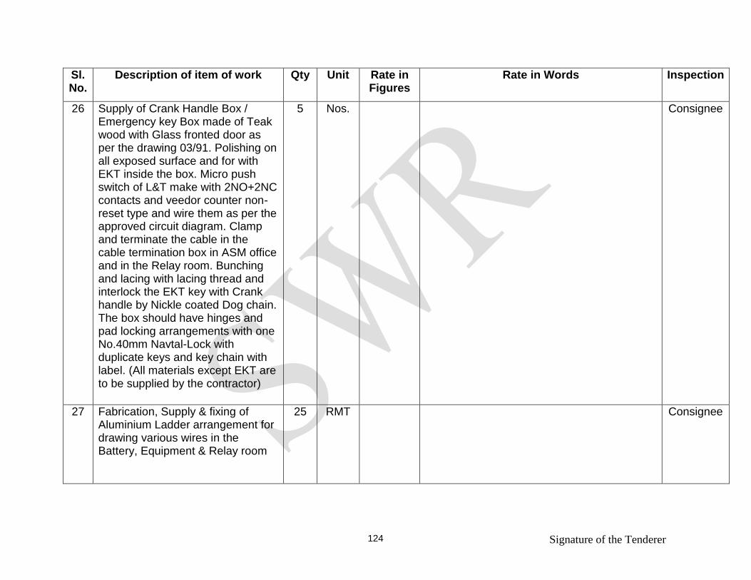
Signature of the Tenderer 124
Sl. No.
Description of item of work Qty Unit Rate in Figures
Rate in Words Inspection
26 Supply of Crank Handle Box / Emergency key Box made of Teak wood with Glass fronted door as per the drawing 03/91. Polishing on all exposed surface and for with EKT inside the box. Micro push switch of L&T make with 2NO+2NC contacts and veedor counter non-reset type and wire them as per the approved circuit diagram. Clamp and terminate the cable in the cable termination box in ASM office and in the Relay room. Bunching and lacing with lacing thread and interlock the EKT key with Crank handle by Nickle coated Dog chain. The box should have hinges and pad locking arrangements with one No.40mm Navtal-Lock with duplicate keys and key chain with label. (All materials except EKT are to be supplied by the contractor)
5 Nos. Consignee
27 Fabrication, Supply & fixing of Aluminium Ladder arrangement for drawing various wires in the Battery, Equipment & Relay room
25 RMT Consignee

Signature of the Tenderer 125
Sl. No.
Description of item of work Qty Unit Rate in Figures
Rate in Words Inspection
28 Supply and painting the S&T gadgets with standard quality of different colours of enamel paints at various locations as per the instructions of JE/SE/SSE-in-charge of site
50 Sq.M
29 Supply of Electronic flasher 12-24V DC / 10A
1 Nos. RDSO Approved
30 Supply of Nav-tal Godrej make locks 50mm with two keys
10 Nos. Consignee
31 Supply of Transformer Rectifier 230V AC/24V DC - 1 Amps to RDSO Spec. IRS: S: 74/89 with amdt. or latest
1 Nos. RDSO Approved
32 Installation of ring Earth Pit which includes the following:-
1 Set
a) Digging/Auguring/Bring of four earth pits of 100mm to 125mm dia to the depth of 2.8 meter
b) Insertion of 3.0 meter electrodes and penetrating it at least 0.2meter by pushing gently with siede hammer where the natural soil is assumed for all four pits

Signature of the Tenderer 126
Sl. No.
Description of item of work Qty Unit Rate in Figures
Rate in Words Inspection
c) Filling of earth pit with Earth Enhancement compound (EEC) in slurry form and backfilling.
d) The exothermic welding material for bonding the earth system is to be procured from RDSO approved firms which includes graphite moulds, clamps, weld-metal powders
e) Carrying out exothermic weld connection on the master earth electrode to with copper tape of 150x25x6mm
f) Carrying out exothermic weld connection on the master earth electrode to with copper tape of 150x25x6mm on master Earth Electrode for connecting two 25Sqmm cables for redundancy.
g) Digging a trench to a depth of at least 0.5m below the ground level and run the two 35Sqmm earth conductor from Earth pit ot MEEB.

Signature of the Tenderer 127
Sl. No.
Description of item of work Qty Unit Rate in Figures
Rate in Words Inspection
h) Termination of two 35Sqmm earth conductor to 300x25x6mm MEEB using copper lugs with stainless steel nut and bolts.
i) MEEB of size 300x25x6mm is to be fixed inside the equipment room with two insulation studs.
j) 300x300x300mm (inside dimension) concrete Earth Pit with a concrete lid, approx. 50mm thick with pulling hooks, shall be provided to cover the Master Earth pit. Back side of the cover will be painted in black and date of the testing and average resistance value shall be written.
33 Supply of 1-inch PVC pipe 60 Mtrs Consignee
34 Cutting of groove on the wall, fixing of 1-inch pipe & drawing the cables through the pipes and resurfacing.
150 RMT
35 Installation of Unit Maintenance free earth as supplied in schedule which includes
8 Nos.

Signature of the Tenderer 128
Sl. No.
Description of item of work Qty Unit Rate in Figures
Rate in Words Inspection
i) Digging of earth to required depth
ii) insertion of electrodes
iii) Filling of earth enhancing compound (Approx.30Kgs).
iv) Provision of exothermic weld connection to copper tape of 25mm x 6mm x150mm -01 no to earth electrodes (All the materials tools and feature required for weld will be arranged by the contractor
v) This includes CC cover 1.5 ft x 1.5ft 1 ft wall thickness 2" with cover 3" thickness.
vi) Cables 35 Sq mm/16Sq mm/10sq mm for connecting earth to bus-bar, bus-bar to Bus-bar, bus-bar to various equipment. Earth electrode of 17 mm dia and 3.0m long high tensile low carbon steel circular rods and outer surface (minimum copper bonding thickness of 250 micron to made requirement of under writer's laboratories (UL) 467-2007 or latest.

Signature of the Tenderer 129
Sl. No.
Description of item of work Qty Unit Rate in Figures
Rate in Words Inspection
vii) Copper strip of 150x25x6mm to be welded with each earth electrode, Copper strip of 300x25x6mm for main equip-potential bus bar, Copper strip of 150x25x6mm sub equip-potential bus bar in relay room, power room and panel room.
viii) Copper tape 25mmx2mm for ring formation of earth enhancement material in bags for each earth electrode. Inspection chamber of site 300mmx300mmx300mm (inside dimention0 of approximate 50mm thick with pulling hooks to cover the earth pits.
Note: The installation of this item shall be carried out by the contractor as per RDSO spec.no. RDSO/SPN/197/2008 or latest and confirming to RDSO Drg. No. SDO/RDSO/E&B/001 or latest
36 Arranging skilled labours at S&T/Proj/Stores at UBL for loading/unloading/stacking of departmental materials
100 Man days

Signature of the Tenderer 130
Sl. No.
Description of item of work Qty Unit Rate in Figures
Rate in Words Inspection
37 Supply of Relay racks Universal type to Drg No. S&T/MFT/291
6 Nos. Consignee
38 Supply of Cable termination racks of size 880mmX2Mtrs
2 Nos. Consignee
39 Supply of Domino type operation cum indication panel 3/4 with LED indicators for tracks, signals, crank handle etc.
1 Nos. Consignee
40 Manufacture, Supply & fixing of Sighting board (Size 535mmx1800mm) with retro reflective tape
2 Nos Consignee
41 Fabrication, Supply and fixing of CALLING ON instruction boards, STOP boards with Engineering grade retro reflective stickers of size 600x900x1200mm GI sheet with MS angle
4 Nos Consignee
42 Supply of Non-deteriorating type of Fuse holders 20A Capacity
150 Nos RDSO
43 Supply of Fuse links 20A to IRS Spec.S.78/92
10 Nos RDSO
44 Supply of Fuse links 10A to IRS Spec.S.78/92
20 Nos RDSO
45 Supply of Fuse links 2A to IRS Spec.S.78/92
120 Nos RDSO
46 Supply of Terminal Block 6-way PBT 25 mm as per RDSO Drg No. SA.23756/Adv/Alt.3 & IRS S. 75/91
350 Nos RDSO

Signature of the Tenderer 131
Sl. No.
Description of item of work Qty Unit Rate in Figures
Rate in Words Inspection
47 Supply of Terminal Block One-way PBT 60mm centre
150 Nos RDSO
48 Supply of Universal locks with 1 Key for every 10 locks
20 Nos Consignee
49 Supply of Earth Leakage Detector as per RDSO Spec.SPN/256//2002 with latest amendment
01 Nos Consignee
50 Supply of cable (Route) tracer (Stanlay Make or similar)
01 Nos Consignee
51 Supply of cable fault locator (Stanlay Make or similar)
01 Nos Consignee
52 Supply of Digital Cross- talk measuring set to RDSO Spec. IRS:TC:45/88 or latest
02 Nos Consignee
53 Supply of Transmission measurement set to RDSO Spec. IRS:TC:43/87 or latest (Aplab make T&M, Model 2031A or better)
02 Nos Consignee
TOTAL
Divisional Signal & Telecom Engineer/Project/
South Western Railway, HUBLI. For and on behalf of the President of India

132
TENDERER’S OFFER Name of the work: Shifting of Up and Down advanced starters outside of slip
siding points and shifting of Relays room at Ugarkhurd station
TENDER NOTICE No: SG/SWR/Proj/UBL/UGR Station
Dated 28.10.2015
I/We undertake to do the above work as per the following:
Sl. No.
Schedule
Estimated amount in Rs.
Tenderer offer on par / above or below (On
par or excess percentage / less percentage) in figures and in words for Sch A
In Figures In Words
01. Schedule `A’ 14,44,981/-
02 Schedule `B’ Itemwise
quotes
(Total value
quoted as per
schedule)
Tenderers should quote individual/item wise rates for schedule `B’ items in the
Railway format only.
TENDERERS TO NOTE
01. Tenderers are requested to quote only percentage of their rates in comparison with
the estimated rates for schedule “A”.
03. Tenderers should quote individual/item wise rates for schedule `B’ items.
EXAMPLE:
If the tenderer is intended to quote their rates on par with estimated rates, they have to
write RATES ON PAR" (in words also)
If the tenderer is intended to quote their rates ABOVE % of the estimated rate, they have to
write " (+) (PLUS)%" (in words also)
If the tenderer is intended to quote their rates BELOW % of the estimated rate, they have
to write"(-) (MINUS)%" (in words also)
Signature of the Tenderer