goodway machine corp....goodway machine corp. series ( gs-400 model shown with optional accessories...
TRANSCRIPT
GS-400 Maximum performance CNC Turning Centers
GOODWAY MACHINE CORP.
SERIES

( GS-400 model shown with optional accessories )
GS-400 Series Construction Spindle Turret Multi-Tasking
Most of today ’s large machines are stil l relying on yesterday ’s technology. Many have common
problems such as: slow rapids, under powered spindles, weak structures, turrets that index at a
snail 's pace, or turrets that are too small to provide adequate tool clearance. The GOODWAY
GS-400 ser ies completely e l iminate these downsides with industr y leading new designs.
Combining tremendous power, s t rength, and speed for the ult imate turning power to
accompl ish today and tomorrow’s most demanding turning applications.
The �rst thing you’ll notice inside the door of the GS-400 series is the massive turret, which boasts a turret disk
over 762 mm in diameter. Blazing fast indexing times of 0.5 seconds from station to station and 1.5 second for
stations at 180 degrees are achieved with servo indexing technology.
Under the covers, you’ll �nd a 45 degrees true slant bed with super wide box ways, and an enormous 2-speed
head stock driven by a 37 Kw ( Peak ) Fanuc motor.
Axes rapids are 20 m/min. on X and 24 m/min. on Z, which are 50~100% faster than the competition.
MAXIMUM PERFORMANCE CNC TURNING CENTERS
Together, these exceptional features generate cutting forces and speed unmatched by any other machine in this
capacity and price range. Furthermore, a standard chip conveyor and separate coolant tank system enhance
production e�ciency and operation convenience.

1
2
Positioning of the programmable base tailstock has
been simpli�ed through use of custom software
interface. The Z-axis carriage automatically locks on
to the base of the ta i lstock and drags i t to the
desi red posit ion.
The built-in bearings quill provide greater rigidity for
heavyloads. The extension and retraction of the quill
is programmable and thrust pressure adjustable.
Performance Features Dimensions Speci�cations
( GS-400L model shown with optional accessories )
2 bed lengths and 3 spindle sizes o�er a total of 6 basic
models con�gurations.
Available live tooling and C-axis capabilities in the GS-400
series allow the machine to perform multiple tasks on a
work piece, such as turning, milling, drill ing, and
tapping. It cuts down manpower and cycle time, while
reducing accuracy lost, which will occur if the part is moved
from machine to machine. ( More on page 9 )

MAXIMUM STRENGTH CONSTRUCTION
( Casting structure of GS-400L model shown )
Major structural components have been combined into one solid platform. The low center of
gravity 45° slant bed design provides the most rigid foundation possible for the headstock,
turret, and tailstock.
By using Finite Element Methods ( FEM ), optimal reinforce ribbings are directly cast into the
one-piece bed structure. Mechanical rigidity has been increased by more than 40 % when
compared to conventional designs. The GS-400 series is capable of per forming super
heavy-duty turning and maintain long-term super high-precision accuracy. More rigidity also
means extended tool life.
Built to endure years and years of rigorous high production turning, the heavily ribbed,
one-piece thermally balanced bed and casting components are of FC35-Meehanite casting
( industry standard is FC25~30 ). FC35 grade cast iron is capable of withstanding much
greater stress without deforming and provides maximum vibration damping, which result in
a machine that will outlast and outperform the competition.
All spindle and servo motors, including drives, are Fanuc alpha i series components to ensure
peak machining performance and accuracy.
X and Z axes are driven by over-sized Fanuc alpha i series absolute AC servo motors, providing
tremendous thrust outputs with faster acceleration and deceleration. Absolute encoder
technology saves time and money by eliminating the use of limit switches, thus, eliminating
referencing axes to home positions and replacing broken limit switches.
GS-400 Series Construction Spindle Turret Multi-Tasking

3
4
C3 class hardened and precision ground ball screws
ensure the highest accuracy and durability
possible. Plus, pretension on all axes minimizes
thermal distortion.
Extra wide hardened and ground box ways are directly formed
into the machine bed and saddle during the casting process.
They are precision machined and widely spaced for maximum
strength. The box way design also provides the rigidity needed
for heavy duty and interrupted turning applications.
The 2 - speed super heavy duty gear head incorporates advance mechanical designs. Mated with a 37 Kw ( Peak ) motor to
provide tremendous amount of low-end torque to handle heavy material removal on large diameter parts.
Both gears and bearings are lubricated and cooled by an oil mist system,
which evenly and e�ciently lubricates the components. This system is
much more advanced and environmental compared to the traditional oil
bath system by eliminating the chance of oil contaminating the bearings
and the use of a oil cooler.
Performance Features Dimensions Speci�cations

ULTIMATE TURNING POWER
With over 2,048 N-m of torque available on the low speed
of the 2-speed gear head, turning tough material with big
diameter is now a simple task.
The heavy-duty headstock is of one-piece casting reinforced
with heat dispensing �ns.
Standard rigid tapping feature provides high-speed precision
tapping without the use of �oating tap holders. Set-up is
easier and depth of thread more accurate, permitting
maximum productivity for tapping operations.
GS-400 Series Construction Spindle Turret Multi-Tasking
Unit : mm
Hydraulic chuck + Hydraulic cylinder 【 Spindle Dimension Drawing 】
1,634 348 984 149 70 43 Ø117.5 M130 x P2.0 1,090 90
1,796 485.5 1,023 210 80.5 40 Ø184 M195 x P3.0 1,125 110
L M O P Q R S T VUN
M130 x P2.0 45 20 Ø123 Ø140 Ø117.5 PCD Ø127 Ø134.6 6-M5 x 12L
M195 x P3.0 63 15 Ø184 Ø218 Ø184 PCD Ø215 Ø285 6-M8 x 16L
max : 24min : 1
max : 42min : 12
max : 38min : 15
max : 85.3min : 55.3
max : 29min : 6
max : 51min : 21
Model
GS-400/L
GS-460/L
Model
GS-400/L
GS-460/L
C ED F G HBA I J K
A
K
L
V
U
S RQ P
M
J H
INO
T
F G
B C D E
GS-400/L Hyd. chuck
GS-460/L Hyd. chuck
GS-460/L Air chuck
c d e fba
40 18 Ø118 Ø130 Ø131 Ø144
– 19 – – Ø205 –
– 19 Ø180 Ø195 Ø205 –
Unit : mm
ba
fedc
f : Spindle I.D. Stepe: Spindle I.D.
d: Draw Tube O.D.c : Draw Tube I.D.
【 Draw Tube Dimension Drawing 】
Model

5
6
Front or Front + Rear Air Chuck Con�gurations
Front + Rear Chuck
P4 grade ( Class 7 ) super-high precision bearings are directly assembled for maximum level of support and
precision. Bearing con�guration is designed for heavy-duty cutting with ultra-smooth performance and
long term durability with a higher level of accuracy.
974 40 223223
Ø20
5
1,745
Ø20
5
(60)
GS-460
By installing air or manual chucks on both the
front and rear of the spindle, it becomes
possible to machine the ends of long workpieces.
This con�guration is especially useful
in threading pipes.
Front chuck
Rear chuck
Workpiece
Performance Features Dimensions Speci�cations
550 0RPM0
10
20
30
40
50
172
500
1000
1500
2000
2500
2048
( N-m ) ( KW )
1660
Constant Torque Constant Output
37 Kw ( 30 min. )
30 Kw ( con. )
Torque Output( N-m ) ( KW )Torque Output
( N-m ) ( KW )Torque Output
( N-m ) ( KW )Torque Output
Torque ( 30 min. )
Torque ( con. )
RPM
10
20
30
40
50
100
2000623
200
300
400
500
600
460
567
Constant Torque Constant Output
37 Kw ( 30 min. )
30 Kw ( con. )
Torque ( 30 min. )
Torque ( con. )
37 Kw ( 30 min. )
30 Kw ( con. )
550 RPM0
10
20
30
40
50
172
500
1000
1500
2000
2500
2048
1660
Constant Torque Constant Output
Torque ( 30 min. )
Torque ( con. )
RPM0
10
20
30
40
50
100
1100623
200
300
400
500
600
460
567
Constant Torque Constant Output
37 Kw ( 30 min. )
30 Kw ( con. )
Torque ( 30 min. )
Torque ( con. )
Unit : mm
Spindle Output —GS-460/LSpindle Output —GS-400/L
Low Speed High Speed Low Speed High Speed
GS-400 Series Construction Spindle Turret Multi-Tasking
15290
35
X-axis Stroke : 340
50
Max
. :12
0
52
40
70
Ø1,01044.5
Spin
dle
Cent
er L
ine
Spindle Center Line
Spindle Center Line
X-axis Stroke : 340
Max. Turning Dia. : Ø610
Ø381
Ø76.2
Ø385
Ø395
15273
X-axis Stroke : 340
18
Ø420
280
15
45
Ø378
Ø60
1
5
2 3
4
9 8
7 6
11 12
10
Ø400
CA-3044
CA-3045
CA-3050
CA-3052
CA-3051CA-30A0
CA-30A8
Unit: mm
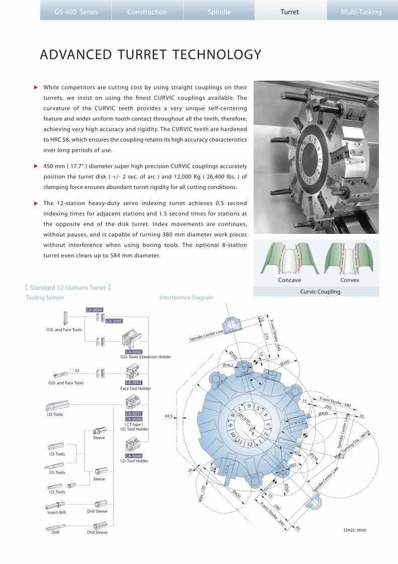
While competitors are cutting cost by using straight couplings on their
turrets, we insist on using the �nest CURVIC couplings available. The
curvature of the CURVIC teeth provides a very unique self-centering
feature and wider uniform tooth contact throughout all the teeth, therefore,
achieving very high accuracy and rigidity. The CURVIC teeth are hardened
to HRC 58, which ensures the coupling retains its high accuracy characteristics
over long periods of use.
450 mm ( 17.7" ) diameter super high precision CURVIC couplings accurately
position the turret disk ( +/- 2 sec. of arc ) and 12,000 Kg ( 26,400 lbs. ) of
clamping force ensures abundant turret rigidity for all cutting conditions.
The 12-station heavy-duty servo indexing turret achieves 0.5 second
indexing times for adjacent stations and 1.5 second times for stations at
the opposite end of the disk turret. Index movements are continues,
without pauses, and is capable of turning 380 mm diameter work pieces
without interference when using boring tools. The optional 8-station
turret even clears up to 584 mm diameter.
( CT type )
ADVANCED TURRET TECHNOLOGY
Concave Convex
Curvic CouplingInterference DiagramTooling System
【 Standard 12-Stations Turret 】
O.D. Tools Extension Holder
Face Tool Holder
I.D. Tool Holder
I.D. Tool Holder
Drill Drill Sleeve
Drill Sleeve
Sleeve
Sleeve
I.D. Tools
I.D. Tools
I.D. Tools
I.D. Tools
O.D. and Face Tools
O.D. and Face Tools
□ 32
Insert drill
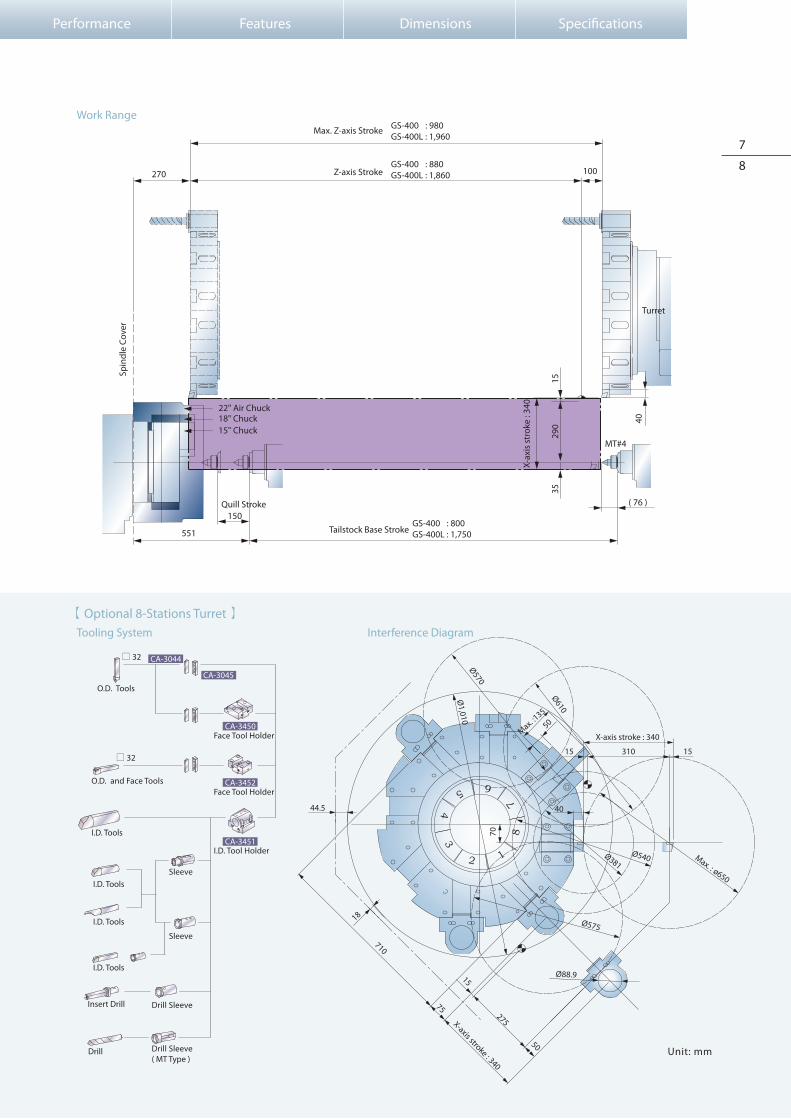
Interference Diagram Tooling System
【 Optional 8-Stations Turret 】
7
8
Work Range
Performance Features Dimensions Speci�cations
( MT Type )
CA-3045
CA-3044
CA-3450
CA-3452
CA-3451
1
5
2
3 4
8 7
6
275
40
15 310 15
44.5
70
X-axis stroke : 340
X-axis stroke : 340
Ø540Ø381Max. : ø650
Ø575
Ø88.9
Max. :135
Ø610
50
Ø570
Ø1,010
50
75
18
710
15
GS-400 : 980GS-400L : 1,960
GS-400 : 880GS-400L : 1,860
150
270
( 76 )
100
40
551GS-400 : 800GS-400L : 1,750
Quill Stroke
Tailstock Base Stroke
Turret
Max. Z-axis Stroke
Z-axis Stroke
Spin
dle
Cove
r
15" Chuck18" Chuck22" Air Chuck
MT#4
X-ax
is s
trok
e : 3
40
1535
290
Unit: mm
O.D. Tools
O.D. and Face Tools
Face Tool Holder
Face Tool Holder
I.D. Tool Holder
Drill Sleeve
Drill Sleeve
Sleeve
Sleeve
I.D. Tools
I.D. Tools
I.D. Tools
I.D. Tools
Insert Drill
Drill
□ 32
□ 32
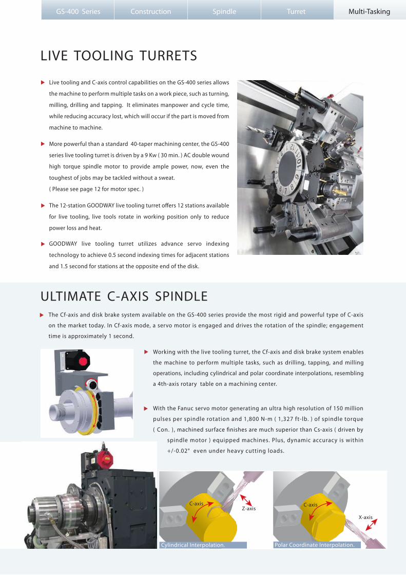
The Cf-axis and disk brake system available on the GS-400 series provide the most rigid and powerful type of C-axis
on the market today. In Cf-axis mode, a servo motor is engaged and drives the rotation of the spindle; engagement
time is approximately 1 second.
ULTIMATE C-AXIS SPINDLE
Working with the live tooling turret, the Cf-axis and disk brake system enables
the machine to perform multiple tasks, such as drilling, tapping, and milling
operations, including cylindrical and polar coordinate interpolations, resembling
a 4th-axis rotary table on a machining center.
X-axis
C-axis
Polar Coordinate Interpolation.
Z-axis C-axis
Cylindrical Interpolation.
GS-400 Series Construction Spindle Turret Multi-Tasking
LIVE TOOLING TURRETS
Live tooling and C-axis control capabilities on the GS-400 series allows
the machine to perform multiple tasks on a work piece, such as turning,
milling, drilling and tapping. It eliminates manpower and cycle time,
while reducing accuracy lost, which will occur if the part is moved from
machine to machine.
More powerful than a standard 40-taper machining center, the GS-400
series live tooling turret is driven by a 9 Kw ( 30 min. ) AC double wound
high torque spindle motor to provide ample power, now, even the
toughest of jobs may be tackled without a sweat.
( Please see page 12 for motor spec. )
The 12-station GOODWAY live tooling turret o�ers 12 stations available
for live tooling, live tools rotate in working position only to reduce
power loss and heat.
GOODWAY live tooling turret utilizes advance servo indexing
technology to achieve 0.5 second indexing times for adjacent stations
and 1.5 second for stations at the opposite end of the disk.
With the Fanuc servo motor generating an ultra high resolution of 150 million
pulses per spindle rotation and 1,800 N-m ( 1,327 ft-lb. ) of spindle torque
( Con. ) , machined surface �nishes are much superior than Cs-axis ( driven by
spindle motor ) equipped machines. Plus, dynamic accuracy is within
+/-0.02° even under heavy cutting loads.
9
10
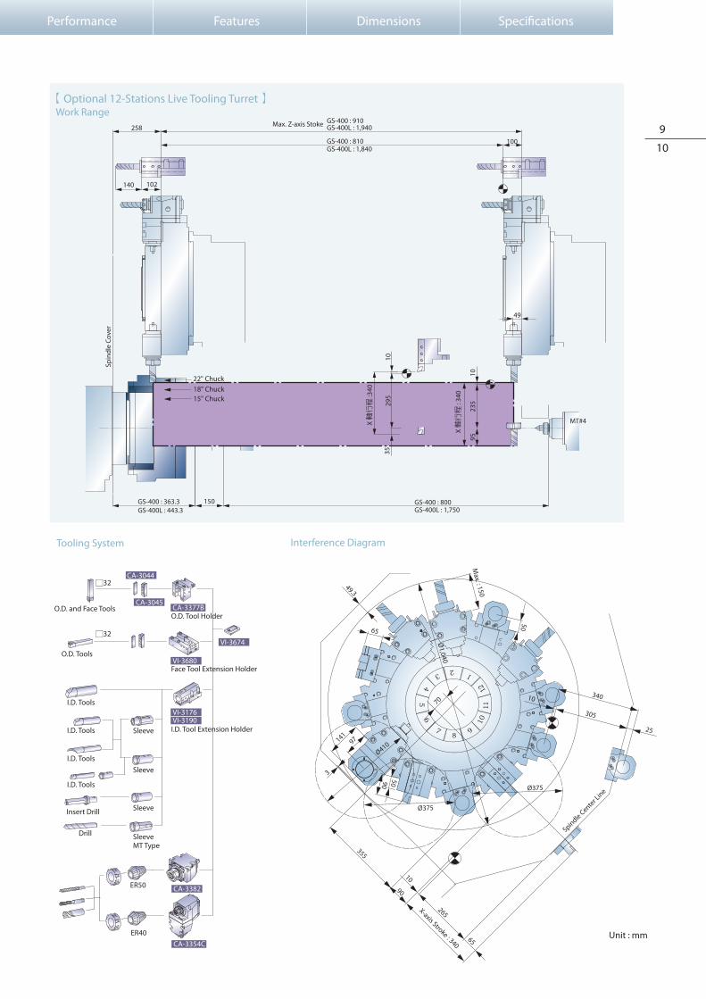
Interference DiagramTooling System
Work Range【 Optional 12-Stations Live Tooling Turret 】
Performance Features Dimensions Speci�cations
X-axis Stroke : 340
Unit : mm
Face Tool Extension Holder
I.D. Tool Extension Holder
O.D. Tool Holder
CA-3045
CA-3044
CA-3382
CA-3354C
ER50
ER40
VI-3674
CA-3377B
VI-3680
VI-3176VI-3190
O.D. and Face Tools
Sleeve
Sleeve
Sleeve
Sleeve
O.D. Tools
I.D. Tools
I.D. Tools
I.D. Tools
I.D. Tools
Drill
Insert Drill
MT Type
□32
□32
70
355
90
10
265
97141
3
Ø410
49.3
65
305
25
340
9050
Ø375
65
Ø1,040
Max. : 150
50
10
Ø375
1112
87
6
9
10
123
45
Spindle Center Line
MT#4
Spin
dle
Cove
r
150
258 GS-400L : 1,940GS-400 : 910
GS-400L : 1,840GS-400 : 810
GS-400L : 443.3GS-400 : 363.3
GS-400L : 1,750GS-400 : 800
100
49
102140
Max. Z-axis Stoke
1023
595
X 軸行程
: 34
0
1029
5
X 軸行程
:340
3518" Chuck15" Chuck
22" Chuck
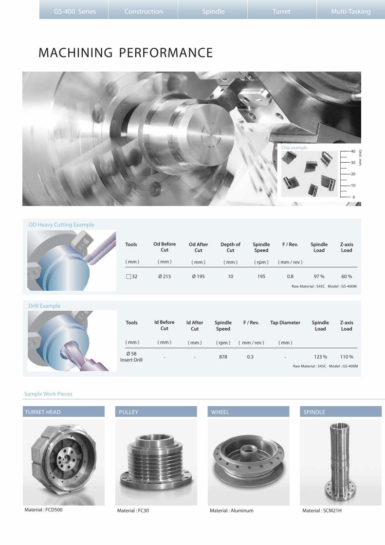
OD Heavy Cutting Example
Drill Example
GS-400 Series Construction Spindle Turret Multi-Tasking
Tools
□ 32
SpindleLoad
97 %
Z-axisLoad
60 %
123 % 110 %
Od BeforeCut
Ø 215
( mm )
Od AfterCut
Ø 195
( mm )
SpindleSpeed
195
( rpm )
Depth ofCut
10
( mm )
F / Rev.
0.8
( mm / rev )
Ø 58Insert Drill
Tools SpindleLoad
Z-axisLoad
( rpm )
SpindleSpeed
878
( mm / rev )
F / Rev.
0.3
( mm )
Id BeforeCut
-
( mm )
Id AfterCut
-
( mm )
Tap Diameter
-
Unit : m
m
0
40
30
20
10
Chip example
Raw Material : S45C Model : GS-400M
Raw Material : S45C Model : GS-400M
( mm )
( mm )
MACHINING PERFORMANCE
Sample Work Pieces
Material : FCD500 Material : FC30 Material : Aluminum Material : SCM21H
TURRET HEAD PULLEY WHEEL SPINDLE

Performance Features Dimensions Speci�cations
GOODWAY Multi-tasking machine can perform the functions below in one setup :
Keyway MillingSide Drilling & Tapping Contour MillingTurning Face Drilling & Tapping
Drive Motor Power ( con. )
Drive Motor Power ( 30 min. )
Drive Motor
Max. tapping Capacity
Max. Milling Capacity
Gear Ratio
7.5 kw ( 10 HP )
9 kw ( 12 HP )
FANUC αP15 / 6,000 i
M 24 mm
Ø 40 mm
1 : 1
Speci�cation of Live Tooling TurretMachining Capability
Drill
End mill
Tapping
200
375
106
Spindle Speed Feedrate Cutting Speed Cutting Depth
Ø 40 HSS
Ø 32 HSS 4-�uteRough End mill
M24 * P3.0
Tools( mm ) ( rpm ) ( mm / min ) ( m / min ) ( mm )
Raw Material : S45C Model : GS-400M
11
12
3,000 rpm2,0000
Revolving Speed
40
80
160
1,0000
3
6
9
12
120
750
95
114
Constant OutputConstant Torque
48
120
318
25
30
8
N/A
25
30
Live Tooling Turret
LIVE TOOLING CUTTING EXAMPLE
Material : ASTM G3000 Material : SCM 415 Material : FC30 Material : S45C
BRAKE DISC COUPLING DURM BRAKE CYLINDER
α P15/6,000i Spindle MotorTorque( N-m )
Output( Kw )
9 Kw ( 30min. )
7.5 Kw ( con. )
Torque ( 30min. )
Torque ( con. )

GS-400 Series Construction Spindle Turret Multi-Tasking
FEATURES
Tri-color status light
The load monitoring function is used to detect abnormal load of tools
by monitoring the variation in spindle motor and servo motor loads
during the cutting process. When abnormal loads are detected, the
machine will stop at program end ( M30 ) or immediately ( feed hold
status ) according to tool life value or tool break value respectively.
Tool Setter
Load Monitoring ( Std. on machines w/ Oi -TD controls )
SeparateCoolant Tank
The optional Renishaw HPRA tool
presetter simpli�es machining setup.
The optional oil skimmer removers
lubrication oil from the coolant tank,
thus, keeping the coolant fresh and
minimizes manual cleaning e�ort.
The standard chip conveyor features adjustable timers that allow the
operator to set operation intervals according to the amount of chips
generated by the machine. Thus, reducing coolant loss to a minimum.
Chip Conveyor
Oil Skimmer
【 Standard Features 】
【 Optional Features 】
3-Jaws chuck w/ Soft Jaws x 1 set
Automatic Steady Rest
Manual Steady RestAir Chuck

S: Standard O: Option–: Not Available C: Contact GOODWAY
13
14
Performance Features Dimensions Speci�cations
8-station turret10-station turret12-station turret12-station live tooling turretTool holder & sleeve packageLive tooling tool holders ( 0˚ x 2 , 90˚ x 2 )*1
Renishaw HPRA tool presetter
TURRET
SPINDLE
WORK HOLDING
MEASUREMENT
AUTOMATIC OPERATION SUPPORT
CHIP DISPOSAL
COOLANT
2-Speed Gear
118 mm ID.180 mm ID.15"18"20" ( 180 mm ID. )21"24"*2Air Chuck
Chuck clampingTailstock thrust
Removeable
3 Kg/cm25 Kg/cm220 Kg/cm2
Right dischargeRear discharge
4 sets ( 8 )8 sets ( 16 )
Main spindle con�gurationRigid tapping & spindle orientationMain spindle disk brakeCs-axis & disk brake for main spindle*1
Hydraulic hollow cylinder for chuck
Hollow 3-jaws chuck & 1 set soft jaws
Hard jawsSpecial work holding chuckIn spindle work stopperSpindle liner ( guide bushing )Foot switch for chuck operationProgrammable base & quill hydraulic tailstockMT#4 dead center quillMT#5 live center quillFoot switch for tailstock operationManual steady restSelf-centering hydraulic steady restFoot switch for steady rest operation
Two-stage programmable pressure
Chip conveyor with auto timer
Chip cart with coolant drainChuck air blowTailstock air blowCoolant gunOil mist collector
Coolant pump
High-pressure coolant systemRoll-out coolant tankOil skimmerCoolant �ow switchCoolant level switchCoolant intercooler system
Bar feederBar feeder interface Gantry-type loader / unloaderAuto door
External M-code output
SSOO
S–OO–OOOOCOOSOOOOOOOOO
OOSOSO
O
SOCSOOOO
S–OOOOO
OOOOOO
SSOO
OOOOOOOOOCOOSSSOOOOOOO
OOSOSO
O
SOCSOOOO
S–OOOOO
OOOOOO
GS-400
GS-460
FANUC CONTROL FUNCTIONS
SAFETY
OTHERS
CONTROL
Heat exchangerA/C cooling system
SB7: 0.025μ sec/step8.4" color LCD10.4" color LCDStandardDynamicSmall - 44 keysLarge -56 keys640m1,280m2,560m4001,0006499400999HRV2 ( 3 )Manual Guide OiManual Guide i *3CAP i -TAlpha i Alpha i
Tri-color machine status light towerWork lightExternal work light
Electrical cabinet
Complete hydraulic systemAdvanced auto lubrication systemFoundation leveling & maintenance tool kitEmergency maintenance electrical part packageOperation & maintenance manuals
Fully enclosed guardingDoor interlock ( incl. Mechanical lock )Impact resistant viewing windowTailstock stroke out - end checkChuck cylinder stroke out - end checkChuck cylinder check valveLow hydraulic pressure detection switchOver travel ( soft limit )Load monitoring function
Fanuc Oi -TD controlFanuc 18i -TB control
SSSSSSSSO
SSOSOSSSSS
SO
SSSSSSSSO
SSOSOSSSSS
SO
GS-400
GS-460
PMC system
Display
Graphic function
Full keypad
Part program storage length
Registerable programs
Tool o�set pairs
Servo control
Conversationalprogramming
Servo motorsSpindle motorsTool Life ManagementTool Nose Radius CompensationBackground editingVariable Lead Thread CuttingPolygon TurningUnexpected disturbance torque detection functionPolar coordinate & cylindrical interporlation*1Multiple ThreadingRun hour & parts counterAuto power o� functionCustom macro BRS-232 portMemory card input/outputEthernetFast ethernet
SSOSOSOS––S–S–––SSO–SSSSSSSSOSSSSSS–O
S–SSS–S–SOSOSOOOS–SOSSOSSSSSOSSSSSSSO
S: Standard O: Option–: Not Available C : Contact GOODWAY 18i - TB
Oi - TD
Above standard & optional features also apply to L models.*1 Standard on M ( live tooling ) models.*2 Tool setter must be deleted.*3 10.4" color LCD option needed.
Speci�cations are subject to change without notice.
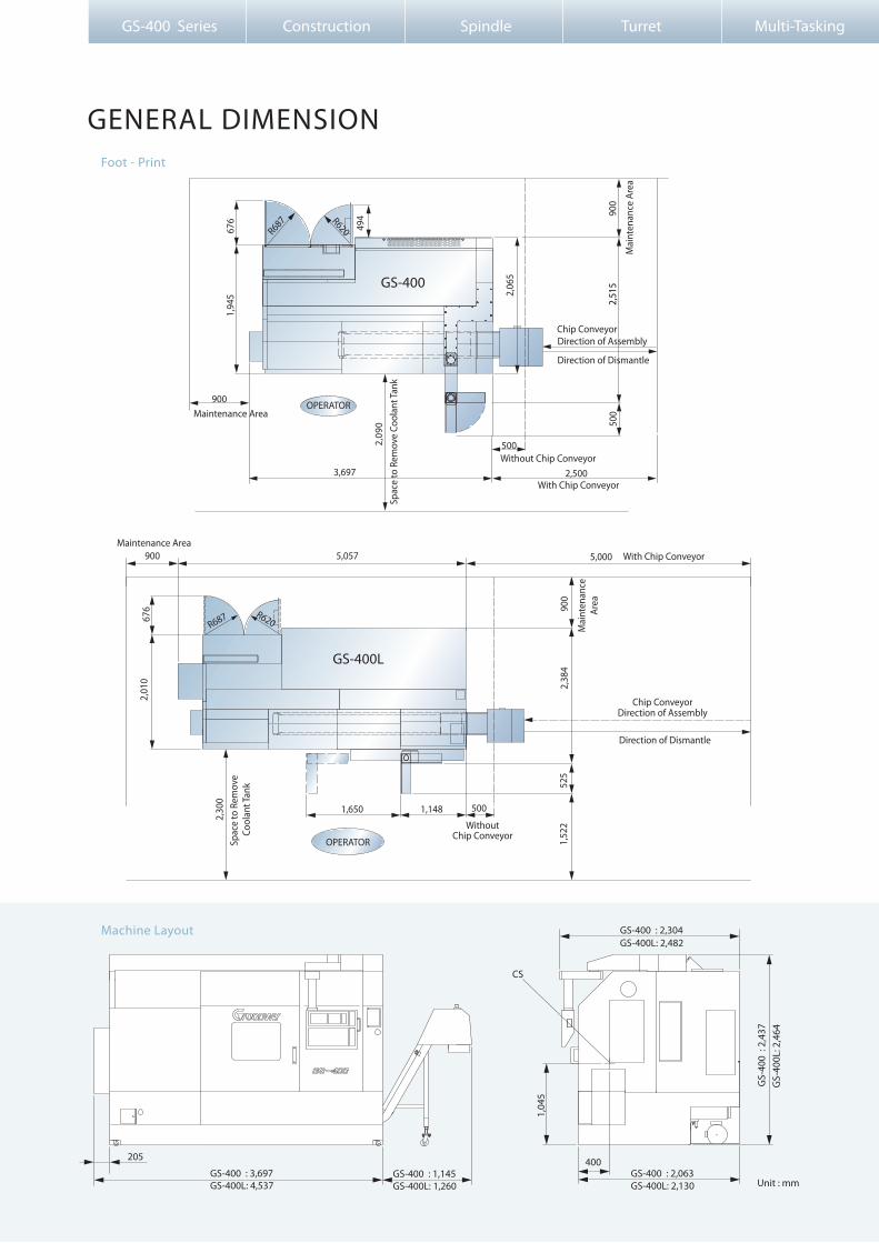
Foot - Print
Machine Layout
GS-400 Series Construction Spindle Turret Multi-Tasking
5,05790
02,
384
1,650
3,697
1,148
5,000
2,30
0
500
676
494
2,06
5
2,51
590
0
900
5002,09
0
2,500
500
1,94
5
2,01
067
6
900
Chip ConveyorDirection of Assembly
Direction of Dismantle
With Chip ConveyorMaintenance Area
OPERATOR
OPERATOR
Direction of Dismantle
Without Chip Conveyor
GS-400
GS-400L
205
1,04
5
CS
400GS-400 : 3,697GS-400L: 4,537 GS-400L: 1,260
GS-400 : 2,063GS-400L: 2,130
GS-
400
: 2,
437
GS-
400L
: 2,4
64
GS-400 : 2,304GS-400L: 2,482
GS-400 : 1,145
R620R687
R620R687
Unit : mm
GENERAL DIMENSION
Spac
e to
Rem
ove
Cool
ant T
ank
WithoutChip Conveyor
Chip ConveyorDirection of Assembly
With Chip Conveyor
Mai
nten
ance
Area
Spac
e to
Rem
ove
Cool
ant T
ank
Maintenance Area
Mai
nten
ance
Are
a
1,52
252
5

Lifting by Forklift
Requirements of the Foundation Lifting by Overhead Crane
INSERT WOOD BLOCK
INSERT WOOD BLOCK
INSERT ( WOOD BLOCK )
Unit : mm
15
16
200 ( 8" )
GS-
400
: 1
,350
GS-
400L
: 1,
600
GS-
400
: 1
,050
GS-
400L
: 1,
500
GS-400 : 3,492
500
200
GS-400L : 4,627
Concrete
Gravel
A
Levelling Block
Hex. Nut M39
Levelling Bolt
Part name
2
3
2
1
N0.
3
CA-1030
NA3900BA
CA-1029
A-Particular
Part NO
1
557
445
A B C D E F G H
GS-400
GS-400L
728 804 895 - 725 862 895 -
728 884 976 879 725 942 976 879
Model
Ø 22 X 4,150L
Ø 22 X 4,240LØ 22 X 4,100L
B
FE
A
G
C D
H
GS-400 bed GS-400L bed
OPERATOR
Top View
65
125
862
APPROXMIN.: 50GS-400 : 2,000
GS-400L : 2,500
Foundation
Performance Features Dimensions Speci�cations
GS-400 : 9-LevelingsGS-400L: 11-Levelings

Max. swing diameter
Swing over saddle
Max. turning diameter
Std. turning diameter
Max. turning length
Max. weight load
Chuck size
Bar capacity
Max. X-axis travel
Max. Z-axis travel
X axis rapids
Z axis rapids
Slide way type
Feed rates
X-axis servo motor
Z-axis servo motor
X-axis ball screw Ø / pitch
Z-axis ball screw Ø / pitch
X / Z axes thrust ( Con. )
CAPACITY
SPINDLE
X & Z AXES
Ø 205 mm ( 8.07" )
Ø 260 mm ( 10.23" )
Ø 20" —
A2-15
550 rpm
1,100 rpm
Ø 130 mm ( 5.11" )
Ø 180 mm ( 7.08" )
Ø 15"
A2-11
550 rpm
2,000 rpm
α30 / 6,000i
30 Kw ( 40 HP )
37 / 45 Kw ( 50 / 60 HP )
623 rpm
V-Belt + Gear Box
3 : 20
27 : 50
2,048 N-m @ 172 rpm ( 30 min. )
567 N-m @ 623 rpm ( 30 min. )
340 mm ( 13.38" )
980 mm ( 38.58" ) / 1,960 mm ( 77.17" )
20 m/min. ( 788 IPM )
24 m/min. ( 945 IPM )
Box Way
1~ 4,800 mm/min. ( 1~189 IPM )
AC 7 Kw ( 9.5 HP , Fanuc α30B / 3,000ί , Absolute encoder, 1,000,000 / rev. )
AC 4 Kw ( 5.5 HP , Fanuc α22 / 3,000ί , Absolute encoder, 1,000,000 / rev. )
Ø 40 mm ( 1.57" ) x P8
Ø 45 mm ( 1.77" ) x P12 / Ø 50 mm ( 1.97" ) x P16
Ø 740 mm ( 29.13" )
Ø 710 mm ( 27.95" )
Ø 610 mm ( 24.01" )
Ø 380 mm ( 14.96" )
950 mm ( 37.40" ) / 1,980 mm ( 77.96" )
850 kg ( 1,870 lbs )
15" ( opt. 18" / 21" / 24" )
Ø 115 mm ( 4.52" )
GS-400 / 400L GS-460 / 460L
22" ( opt. Air Chuck )
Ø 205 mm ( 8.07" )
20" ( opt. Hyd. Chuck )
Ø 180 mm ( 7.09" )
Hole through spindle
Spindle bearing diameter
Hydraulic cylinder
Spindle nose
Spindle motor type
Motor output ( Con. )
Motor output ( 30 min. / Peak )
Motor full output speed
Spindle drive system
Spindle drive ratio
Spindle speed range
Spindle full output speed
L
H
L
H
L
H
Z : 1,175 Kg ( 2,586 lbs. )X : 1,923 Kg ( 4,232 lbs. )
Stations
Indexing drive
Indexing speed
Accuracy
OD tool shank size
ID tool shank size
TURRET
12
Fanuc AC Servo motor α22 / 3,000 i
0.5 sec. Adjacent / 1.5 sec. 180 degrees ( Single step )
Positioning : ± 0.00069°, Repeatability : ± 0.00027°
□ 32 mm
Ø 60 mm ( Opt. 75 mm )
GS-400 Series Construction Spindle Turret Multi-Tasking
MACHINE SPECIFICATIONS

17
18
950 mm / 2,000 mm ( 37.40" / 78.74" )
Ø 640 mm ( 25.19" )
12
12 ( Live tooling tools rotate in working position only )
AC 7.5 / 9 Kw ( 10 / 12 HP , Fanuc αp15 / 6,000i , Absolute encoder, 1,000,000 / rev. )
120 N-m @ 750 rpm [ 30 min. ]
Fanuc AC Spindle motor
0.5 sec. ( Adjacent ) / 1.5 sec. 180 degrees ( Single step )
□ 32 mm
Ø 60 mm
4 ~ 34 mm ( 0.16" ~ 1.34" ) ER 50 collets
10 ~ 4,400 RPM
Quill center taper
Quill diameter / travel
Tailstock base travel
Programmable quill / base
Programmable base type
MT#4 ( Dead center ) / MT#5 ( Live center opt. )
Ø 110 mm ( 4.33" ) / 150 mm ( 5.90" )
Yes / Yes
Position by Z-axis
Speci�cations are subject to change without notice.
GENERAL
Max. turning length
Max. turning diameter
Stations
Live tooling stations
Live tooling drive motor ( Con. / 30 min. )
Live tooling torque
Indexing drive type
Index speed
OD tool shank size
ID tool shank size
Live tooling shank size
Live tooling RPM range
LIVE TOOLING TURRET ( OPTIONAL )
TAILSTOCK
Cf-axis drive motor
Cf-axis drive ratio
Cf-axis rapid
Cf-axis torque output ( Con. )
Min. spindle indexing angle
Dynamic accuracy
Cf-AXIS SPINDLE ( OPTIONAL )
Positioning accuracy ( X / Y / Z )
Repeatability ( X / Y / Z )
CNC control
Voltage / Power requirement
Air pressure
Hydraulic tank capacity
Coolant tank capacity
Coolant pump
Machine weight
Dimensions L × W × H
GS-400 / 400L GS-460 / 460L
± 0.005 mm ( ± 0.0002" )
± 0.003 mm ( ± 0.0001" )
Fanuc Oi - TD ( Opt. 18i - TB )
AC 200 / 220 +10% to -15% 3 phase / 64 KVA
6 kgf / cm2 ( 80 PSI )
15 L ( 3.3 gal. )
1 Kw rated at 90 PSI
320 L ( 84.5 gal. )240 L ( 63.5 gal. )
15,000 Kg ( 33,000 lbs. )
4,830 x 2,465 x 2,465 mm( 190.16" x 97.05" x 97.05" )
11,000 Kg ( 24,200 lbs. )
3,700 x 2,305 x 2,440 mm( 145.68" x 90.75" x 96.06" )
800 mm ( 31.49" ) 1,750 mm ( 68.89" )
α12i
1 : 150
20 rpm
1,800 N-m ( 1,327 ft-lbs )
0.001°
± 0.02°
Performance Features Dimensions Speci�cations
Copyr ight 2010 by Goodway Machine Corp. Al l r ight reservedG-GS-400 SERIES-EN-F-20100224
No.589, Chengyang Road,Xiang Cheng Economic Development District Suzhou City, Jiangsu, ChinaTEL : + 86-512-6576-3699FAX : + 86-512-6576-7299Website : www.goodwaycnc.com.cnE-mail : [email protected]
GOODWAY MACHINE CORP.GOODWAY (SUZHOU) MACHINE CORP.
No.13, 5Th Road,Taichung Industrial Park,Taichung City, 407, Taiwan, R.O.C.TEL : + 886-4-2359-1226FAX : + 886-4-2359-0536Website : www.goodwaycnc.comE-mail : [email protected]
No. 38, Keyuan Road, Central Taiwan Science Park.Taichung, Taichung City, 407, Taiwan, R.O.C.TEL : + 886-4-2463-6000FAX : + 886-4-2463-9600
Headquarters :
Central Taiwan Science Park Branch :