good polb qms -jul24,2013
TRANSCRIPT

The Port of Long Beach Quality Management System
QUALITY MANAGEMENT SYSTEM
(QMS)
PROGRAM MANAGEMENT DIVISION
File Name: Quality Management System Version Number: Rev 1.0 Version Date: 07/24/2013

Quality Management System 07/24/13 – Rev. 1.0
Table of Contents
Terms and Definitions
Abbreviations and Acronyms .................................................................................................. i
Definitions ............................................................................................................................. ii
Icons and Graphics .............................................................................................................. vi
Introduction
Introduction ......................................................................................................................... vii
1.0 SECTION ONE: QUALITY MANAGEMENT SYSTEM
1.1 OVERVIEW ..................................................................................................................1-1
1.1.1 Overall Quality Goals ...........................................................................................1-6
1.1.2 The QMS Objectives ............................................................................................1-6
1.1.3 Document Interface .............................................................................................1-6
1.1.4 Best Practices ......................................................................................................1-7
1.2 QUALITY METHODOLOGY ........................................................................................1-7
1.2.1 Quality Process Architecture ................................................................................1-7
1.2.2 Metric Collection ..................................................................................................1-8
1.2.3 POLB Document Control .....................................................................................1-8
1.2.4 Unifier ..................................................................................................................1-9
1.2.5 Design Criteria, Standard and CADD Requirements ............................................1-9
1.2.6 Lessons Learned and Continuous Process Improvement ....................................1-9
1.3 ROLES AND RESPONSIBILITIES ............................................................................ 1-10
1.3.1 Quality Oversight Team (QOT) .......................................................................... 1-11
1.3.2 DCHE – Division Support Services .................................................................... 1-12
1.3.3 DCHE – Program Management ......................................................................... 1-12
1.3.4 Quality Assurance Manager ............................................................................... 1-13
1.3.5 Program Manager .............................................................................................. 1-13
1.3.6 Designer ............................................................................................................ 1-14

Quality Management System 07/24/13 – Rev. 1.0
1.3.7 Specifications Manager ..................................................................................... 1-15
1.3.8 Design Reviewer ............................................................................................... 1-16
2.0 SECTION TWO: DESIGN QUALITY MANAGEMENT PLAN
2.1 DESIGN QUALITY MANAGEMENT PLAN ...................................................................2-1
2.1.1 Quality Management Plan Overview ....................................................................2-2
2.1.2 Project Work Plan ................................................................................................2-3
2.1.3 Prior Design Documents ......................................................................................2-3
2.1.4 Designer’s Project Personnel’s Roles and Responsibilities ..................................2-4
2.1.5 Design Project Manager / Design Manager .........................................................2-4
2.1.6 Design Quality Assurance Manager .....................................................................2-5
2.1.7 Discipline Leaders ...............................................................................................2-5
2.1.8 Design (Technical) Staff ......................................................................................2-6
2.1.9 Administrative Staff ..............................................................................................2-6
2.1.10 Project Quality Responsibilities ..........................................................................2-6
2.1.11 Design Quality Assurance Manager ...................................................................2-7
2.1.12 Quality Assurance Certification ..........................................................................2-7
2.1.13 Preparing the Submittal Package .......................................................................2-7
2.2 DESIGN DELIVERY PROCESS ...................................................................................2-8
2.2.1 Overview of Design Delivery ................................................................................2-8
2.2.2 Design Development Process ..............................................................................2-8
2.2.2.1 Design Initiation................................................................................... 2-11
2.2.2.2 Design Review Program & Quality Assurance Certification ................. 2-12
2.2.3 Comment, Response and Resolution Process ................................................... 2-14
2.2.3.1 Comment, Response and Action Codes .............................................. 2-15
2.3 DOCUMENT MANAGEMENT .................................................................................... 2-17
2.3.1 Quality Records Filing Structure ........................................................................ 2-17
2.4 QUALITY ASSURANCE PROGRAM .......................................................................... 2-17
2.4.1 Preparing for Audits and Surveillances .............................................................. 2-18
2.4.2 Accommodating Audits and Surveillances ......................................................... 2-18
2.5 TRAINING AND IMPLEMENTATION ......................................................................... 2-19

Quality Management System 07/24/13 – Rev. 1.0
3.0 SECTION THREE: DESIGN REVIEW PROGRAM
3.1 INTRODUCTION ..........................................................................................................3-1
3.1.1 Design Review .....................................................................................................3-1
3.2 DESIGN REVIEW PROGRAM .....................................................................................3-2
3.2.1 Design Review and Approval Process .................................................................3-4
3.2.2 Design Review Methodology ...............................................................................3-5
3.2.3 Project Risk Assessment (Activity 1) ....................................................................3-7
3.2.3.1 Scope of Work for Design Reviewer (Activity 2) ....................................3-9
3.2.3.2 Design Review Technical Considerations..............................................3-9
3.2.3.3 Types of Design Reviews to Consider ...................................................3-9
3.2.3.4 Design Reviewer’s Qualifications ........................................................ 3-11
3.2.4 Designer Submits Package to POLB Program Manager (Activity 3) .................. 3-11
3.2.4.1 Designer’s Responsibility Prior to a Submittal ..................................... 3-12
3.2.5 Program Manager Confirms Submittal Package (Activity 4) ............................... 3-12
3.2.6 Optional Orientation Meeting (Activity 5) ............................................................ 3-13
3.2.7 Design Reviewers Conduct Reviews (Activity 6) ................................................ 3-13
3.2.8 Documenting Review Comments (Activity 7) ..................................................... 3-13
3.2.9 Consolidate Review Comments (Activity 8) ....................................................... 3-13
3.2.10 Program Manager Reviews Comments (Activity 9) .......................................... 3-13
3.2.11 Designer Evaluates and Provides Initial Response (Activity 10)....................... 3-13
3.2.12 Comment Resolution and Implementation (Activity 11) .................................... 3-14
3.3 METRICS OBTAINED FROM THE DESIGN REVIEW ............................................... 3-16
3.4 SUMMARY ................................................................................................................. 3-16
4.0 SECTION FOUR: QUALITY ASSURANCE PROGRAM
4.1 INTRODUCTION ..........................................................................................................4-1
4.1.1 Quality Assurance Management ..........................................................................4-1
4.1.2 Roles and Responsibilities ...................................................................................4-2
4.1.3 Best Practices ......................................................................................................4-3
4.1.4 Goals and Objectives ...........................................................................................4-3
4.2 PROGRAM OVERVIEW ...............................................................................................4-3
4.2.1 Program Principles ..............................................................................................4-5

Quality Management System 07/24/13 – Rev. 1.0
4.2.2 Quality Assurance and Continuous Improvement Program ..................................4-5
4.2.3 Develop Quality Management Plan ......................................................................4-6
4.2.4 Implementation ....................................................................................................4-6
4.2.5 Program Monitoring .............................................................................................4-7
4.3 POST DESIGN QUALITY ASSURANCE ACTIVITIES................................................ 4-10
4.3.1 Bid & Award ....................................................................................................... 4-10
4.3.2 Construction ...................................................................................................... 4-10
4.4 THE ROLE OF QUALITY ........................................................................................... 4-11
4.5 GATE REVIEW .......................................................................................................... 4-12
4.6 REPORTING .............................................................................................................. 4-12
4.7 TRAINING .................................................................................................................. 4-12
5.0 SECTION FIVE: INTEGRATION
5.1 INTRODUCTION ..........................................................................................................5-1
5.1.1 Integration Flowcharts .........................................................................................5-2
5.1.2 Systems Overview ...............................................................................................5-3
5.1.3 Potential Conflicts ................................................................................................5-3
5.1.4 Other Documents Reviewed ................................................................................5-5
List of Figures
Figure 1-1: Quality Management System Overview ............................................................1-2
Figure 1-2: Design Delivery Methodology ...........................................................................1-5
Figure 1-3: Program Management Division Organization Chart ........................................ 1-10
Figure 2-1: Design Delivery Process ..................................................................................2-9
Figure 2-2: Design Development Process ........................................................................ 2-10
Figure 2-3: Design Review and Approval Process ............................................................ 2-13
Figure 2-4: Comment, Response & Resolution Log Sheet................................................ 2-16
Figure 3-1: Design Delivery Process ..................................................................................3-4
Figure 3-2: Design Review Methodology ............................................................................3-6
Figure 3-3: Design Reviewer’s Scope of Work ...................................................................3-7
Figure 3-4: Comment, Response & Resolution Log Sheet................................................ 3-15
Figure 4-1: Quality Organizational Chart ............................................................................4-2

Quality Management System 07/24/13 – Rev. 1.0
Figure 4-2: Quality Assurance and Continuous Improvement Program ..............................4-4
Figure 4-3: Quality Assurance Program Monitoring ............................................................4-9
Figure 5-1: Integration – Master Planning Phase ................................................................5-6
Figure 5-2: Integration – Project Initiation Phase ................................................................5-7
Figure 5-3: Integration – Feasibility / Pre-Design Phase .....................................................5-8
Figure 5-4: Integration – Design Phase, 15% Milestone .....................................................5-9
Figure 5-5: Integration – Design Phase, 50% Milestone ................................................... 5-10
Figure 5-6: Integration – Design Phase, 100% Milestone ................................................. 5-11
Figure 5-7: Integration – Design Phase, Final Review ...................................................... 5-12
Figure 5-8: Integration – Bid and Award Phase ................................................................ 5-13
Figure 5-9: Integration – Construction Phase ................................................................... 5-14
Figure 5-10: Integration – Project Closure Phase ............................................................. 5-15
List of Appendices
Appendix A: POLB Monthly Status Report
Appendix B: Itemized Submittal List
Designer’s QC Activity Schedule
Design Control Log
Sample QA Certification
Appendix C: Sample Design Quality Management Plan (DQMP)
Appendix D: Quality Control Checklists
Appendix E: Sample Surveillance/Audit Report
Sample Performance Metrics
Sample Dashboard
Quality Assurance Planning Log

TERMS AND DEFINITIONS
Quality Management System
07/24/13 – Rev. 1.0 i
ABBREVIATIONS AND ACRONYMS
The following list of abbreviations and acronyms is provided to ensure a uniform understanding of terms as they apply to this Quality Management System.
BR Caltrans
Bid-ability Review California Department of Transportation
CADD Computer Aided Drafting & Design CAPA CAR
Corrective and Preventive Action Corrective Action Request
CCO Construction Change Order CEQA California Environmental Quality Act CM Construction Management, Construction Manager CPC Capital Projects Coordinator CR CRR
Constructability Review Comment, Response, and Resolution
CSF Critical Success Factor DCHE DL
Deputy Chief Harbor Engineer Deliverable
DQAM Design Quality Assurance Manager DQMP Design Quality Management Plan DR Discipline Review EDMS Electronic Data Management System EIR Environmental Impact Report EIS GPCS
Environmental Impact Statement Guidelines for Professional Consulting Services
IDR Inter-Discipline Review ISO International Organization of Standardization KPI Key Performance Indicator MR Management Review NEPA National Environmental Policy Act NTP Notice to Proceed PCS Professional Consulting Services PDM Project Delivery Manual PM PjM PMP
Program Management, Program Manager Project Management, Project Manager Project Management Plan
POLB Port of Long Beach QA Quality Assurance QAM Quality Assurance Manager QC Quality Control QM Quality Manager QMP Quality Management Plan QMS Quality Management System

TERMS AND DEFINITIONS
Quality Management System
07/24/13 – Rev. 1.0 ii
Abbreviations and Acronyms Continued:
QOT RAAM RAM RFI RFP SOW SR WA
Quality Oversight Team Risk Analysis and Assessment Manual Risk Assessment Manual Request for Information Request for Proposal Scope of Work State Route Work Authorization
WBS Work Breakdown Structure VE Value Engineering
DEFINITIONS
The following definitions are provided to ensure a uniform understanding of terms as they apply to this Quality Management System
Audit: A documented activity performed in accordance with written procedures or checklists to verify, by examination and evaluation of objective evidence, that applicable elements being examined have been developed, documented, and effectively implemented in accordance with specified requirements.
Change Control: An element of overall Configuration Management. This is a systematic evaluation, coordination and approval or disapproval of any change to what was initially or previously approved. It also includes the performances of those actions necessary to ensure that the final, delivered configuration of a system completely matches its technical description in the approved engineering drawings, specifications, and related documents.
Change Management: There are two types of Change Management. One type refers to technical change within a complex system of hardware or software. The second type refers to a process change regarding how the overall flow of work proceeds from one set of activities to another. In this document, because the focus is on a Quality Management Program, change management refers to the active coordination, planning and implementation of new tasks and processes in the project development and project management process.
Checking: The word checking is used in this document to refer to the detailed accuracy checks performed by a Checker during the check of calculations or drawings.
Compliance: Following or conforming to the rules regarding the requirements of the quality program.
Computer Automated Design & Drafting (CADD): The use of computer software to create, modify, analyze or optimize a design or other technical drawing.

TERMS AND DEFINITIONS
Quality Management System
07/24/13 – Rev. 1.0 iii
Configuration Control: Configuration control is defined as managing, documenting, and securing proper approvals for any changes to the initial configuration and pertinent features of the Project.
Configuration Management: A management method of producing an end result which comprises three elements: product identification, change control and configuration control. Configuration management may be distributed throughout a number of organizational entities.
Conformance: Following the rules and regulations regarding the quality program
Constructability Review: A review of plans and specifications for buildability and bidability.
Controlled Document: This is a document which contains information intended for restricted distribution & revision control. The document must be periodically reviewed and updated, as required.
Corrective Action: Documented commitment of specific action being planned or implemented to resolve a known and identified condition or conditions adverse to Quality.
Corrective Action Request (CAR): A document issued to the consultant whose activities are not meeting requirements. A CAR is a time sensitive document since there is a sense of urgency to close the CAR to properly remedy the root cause.
Deficiency: A deviation from the design or specification requirements.
Design: A technical and management process which creates, fashions, executes, or documents a set of plans, drawings, and specifications to fulfill a pre-determined set of requirements.
Design Criteria: Standards that will be used to prepare the design.
Design Review: The review of design for the purpose of detection and remedy of design deficiencies which would affect fitness-for-use and environmental aspects of the product, process or service, and/or identification of potential improvements of performance, safety and economic aspects.
Design Standards: Standards that are required by the reviewing and approving agency.
Design Verification: The process of reviewing, confirming or substantiating the design by one or more methods to provide assurance that the design meets the specified design input. Acceptable methods of design verification are design reviews, alternate calculations, qualification testing or combinations thereof.
Deviation: A specific written authorization to depart from a particular code standard, design, specification, drawing, or other requirement. A deviation differs from a design change in that an approved design change requires formal approval and revision of the documentation
TERMS AND DEFINITIONS
Quality Management System
07/24/13 – Rev. 1.0 iv
defining the affected item, whereas a deviation does not contemplate revision of the applicable specification or drawing.
Directives: A specific set of rules and/or requirements that have been issued by POLB Senior level management that must be followed.
Discipline Review: Checking design documents within the originating discipline.
Disposition: A statement describing the manner in which a deficiency or nonconformance is to be resolved.
Document: An original or official paper serving as the basis, proof, or support of something. Also, writing conveying information. Documents may include, but are not limited to, loose-leaf or bound books, drawings (tracings and/or reproductions), engineering calculations, procedures, specifications, standards, reports, manuals, and other material generated which affects quality.
Document Control: Document control is the function of managing the document flow and storage in an organization through various functions and processes. These include maintaining files and using proper distribution and revision procedures.
Documentation: Any written or pictorial information describing, defining, specifying, reporting, or certifying activities, requirements, procedures, or results.
Guidelines: Particular provisions which are considered good practice but which are not mandatory in programs intended to comply with this standard. The term “should” denotes a guideline; the term “shall” denotes a mandatory requirement.
Inter-Discipline Review: The review of design documents by engineering disciplines other than the originating discipline.
Non-Compliance: This refers to the behavior of people or organizations who are stakeholders or participants in the Project Development Process and are NOT following the rules regarding the requirements of the quality program.
Non-Conformance: A discrepancy in characteristic, documentation, or procedure which affects form, fit or function and renders the quality of an item or service unacceptable or indeterminate in regard to meeting all relevant project requirements.
Objective Evidence: Any statement of fact, information, or record, either quantitative or qualitative, pertaining to the Quality of an item or service based on observations, measurements or tests which can be verified.
Peer Review: A Peer Review is a type of engineering review that refers to a review of technical documents conducted by a team of peers with assigned roles.

TERMS AND DEFINITIONS
Quality Management System
07/24/13 – Rev. 1.0 v
Preliminary Design Review: A design review which takes place after conceptual design and prior to release for Preliminary Design.
Procedure: A document that specifies or describes how an activity is to be performed. It may include methods to be employed, equipment or materials to be used, and sequence of operation.
Quality Assurance (QA): The act of checking to make sure that the planned and systematic quality processes and requirements have been followed. In addition, it involves a pro-active analysis of these quality processes so they can be upgraded and improved on a regular basis.
Quality Audit: A systematic and independent examination to determine whether quality activities and related results comply with planned arrangements, and whether these arrangements are implemented and are suitable to achieve the stated objective.
Quality Control (QC): The act of checking, testing, or measuring the specific results of a product or service to insure that it meets the desired system specifications or requirements. QC is usually reactive.
Quality Management: That aspect of the overall management function that manages, determines, and implements the Quality Policy.
Quality Oversight Team: A team of senior management personnel that provide the quality leadership and advises on adjustments to the program.
Quality Policy: The overall quality mission and direction of an organization as it regards quality.
Quality Procedure: A procedure describing the method(s) used to meet quality requirements and determine how functional organizations collaborate to accomplish these requirements.
Quality Program: The coordinated execution of applicable QA and QC plans and activities for a project.
Quality System: The organizational structure, responsibilities, procedures, processes and resources for implementing Quality Management.
Surveillance: Monitoring, witnessing or observing to verify whether or not an item or activity conforms to specific requirements.
TERMS AND DEFINITIONS
Quality Management System
07/24/13 – Rev. 1.0 vi
ICONS & GRAPHICS
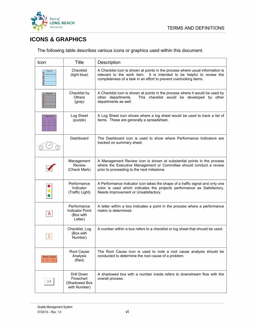
The following table describes various icons or graphics used within this document.
Icon Title Description
Checklist (light blue)
A Checklist icon is shown at points in the process where usual information is relevant to the work item. It is intended to be helpful to review the completeness of a task in an effort to prevent overlooking items.
Checklist by Others (gray)
A Checklist icon is shown at points in the process where it would be used by other departments. This checklist would be developed by other departments as well.
Log Sheet (purple)
A Log Sheet icon shows where a log sheet would be used to track a list of items. These are generally a spreadsheet.
Dashboard The Dashboard icon is used to show where Performance Indicators are tracked on summary sheet.
Management Review
(Check Mark)
A Management Review icon is shown at substantial points in the process where the Executive Management or Committee should conduct a review prior to proceeding to the next milestone.
Performance Indicator
(Traffic Light)
A Performance Indicator icon takes the shape of a traffic signal and only one color is used which indicates the projects performance as Satisfactory, Needs Improvement or Unsatisfactory.
Performance Indicator Point
(Box with Letter)
A letter within a box indicates a point in the process where a performance metric is determined.
Checklist, Log (Box with Number)
A number within a box refers to a checklist or log sheet that should be used.
Root Cause Analysis
(Red)
The Root Cause icon is used to note a root cause analysis should be conducted to determine the root cause of a problem.
Drill Down Flowchart
(Shadowed Box with Number)
A shadowed box with a number inside refers to downstream flow with the overall process.

INTRODUCTION
Quality Management System
07/24/13 – Rev. 1.0 vii
INTRODUCTION
The Program Management Division is implementing a Quality Management System to help improve the project delivery process. The Program Management Division has established a goal to reduce the ambiguity in design documents that could lead to cost, construction, or delivery problems later on through a formal Quality Management System (QMS).
This Quality Management System establishes processes and procedures that the Division Managers, Program Managers, Designers (POLB or Consultants), Design Reviewers (POLB or Design Review Consultants) can use to help consistently and reliably deliver successful design and construction projects.
The QMS starts with understanding our customer needs, identifying the sub systems for the Project Delivery Process and ending with a successful project that satisfies our customer.
The QMS is presented in five parts:
• Section One: The Quality Management System • Section Two: Design Quality Management Plan (Designer’s) • Section Three: Design Review Program (Design Reviewers) • Section Four: Quality Assurance Program • Section Five: Integration
The QMS focuses on the design process starting in Pre-Design and continues through Final Design. Once the project goes into construction, design changes may occur due to multiple circumstances. Therefore, to have a continuous improvement and lessons learned program, a feedback loop during construction is necessary. The following discussion briefly describes the content of Section One through Five:
Section One: Quality Management System
Section One discusses the elements of the Quality Management System that are implemented on a division-wide scale and relevant from a division-wide perspective. It also discusses a high level quality methodology and the quality principles that are followed throughout the Program Management (PM) Division. The Quality Management Program is governed by the Quality Oversight Team who is made up of senior management. The Program Managers and Quality Assurance Manager prepare and submit monthly reports that describe the quality encounters during the reporting period.
The Project Delivery Manual presents the Port of Long Beach’s Project Delivery Process which has seven distinct phases. The process begins with Master Planning and continues through Warranty and Operations & Maintenance. This QMS focuses only on the design development and quality activities through the Design Phase. The Quality Methodology describes the quality activities and discusses how it integrates into the overall Design Phase

INTRODUCTION
Quality Management System
07/24/13 – Rev. 1.0 viii
of the Project Delivery Process. In Section One, exhibits are used to depict these phases, and a high level view of how they integrate together to make up the overall process.
The design of infrastructure projects is accomplished through multiple iterations of a design cycle. Each design cycle (or milestone) increases the precision and accuracy of the design documents. This continues until a point is reached that value is no longer added to the end product. It is accepted that engineering is not a perfect science but it is an accurate science. The goal is to eliminate human errors by implementing an improved quality management system that will help ensure that the contractor builds what was intended the first time.
Each design milestone has a Design Review Cycle and quality related tasks that are performed at strategic points during the design development. The Quality Tasks and Deliverables show how the Quality Methodology is tightly integrated into the project delivery process. In addition, the first part of this document describes key roles and responsibilities for the PM Division Level that will have a significant impact on the overall quality for the Division’s Capital Improvement Program, not just a single project or program of projects.
Section Two: Design Quality Management (Designer)
The second section of the QMS focuses on the Designer’s roles and responsibilities for managing the quality of the design deliverables. The Designer may be internal to the POLB or a Design Consultant. One of the requirements of the Designer is to develop a Quality Management Plan for the project that is tailored to the unique needs of that particular design assignment. There must be a minimum threshold of quality requirements that are met for the project development process that include quality control and quality assurance processes and procedures that are required by the Designer. The Designer must prepare and submit a Design Quality Management Plan (DQMP) that meets these minimum thresholds for each project assigned. These requirements are implemented by the Designer and monitored by the Program Management Division’s Quality Assurance Manager throughout each project.
The Designer’s DQMP will focus on the quality activities needed for their Internal Reviews that take place through the design development and prior to each submittal. The typical design cycle for engineering design projects occurs at four major design review milestones, 15%, 50%, 100% and Final Design and coordinated the design package with the Program Manager for an External Review.
Section Three: Design Review Program (Design Reviewer)
The third section of the QMS focuses on the Design Review process that is conducted by the POLB staff or a Design Review Consultant. A Risk-Based Review approach requires that the risks be identified prior to the design review start, and the design review would generally concentrate 80% of the energy on the risk areas. The remaining 20% would be invested in the entire design package. Risks can be categorized as technical, resource, management, schedule, budget, environmental or material supply. These risk areas are

INTRODUCTION
Quality Management System
07/24/13 – Rev. 1.0 ix
determined by historical construction issues, items that required assumptions, areas where unknowns or insufficient data is available, availability of highly qualified designers, or aggressive design schedules.
Regardless if the design review is conducted by the POLB or a Design Review Consultants, it is essential that the reviewer have a clear understanding of the design requirements, design criteria, design standards, directives, specifications and CADD requirements for the design review. These requirements must be documented and supplied to both the designers and the Design Reviewer.
At each design milestone (15%, 50%, 100% and Final), this is the portion of the quality process which will focus on the review of the design package by either the POLB subject matter experts from each engineering discipline, or by outside design review consultants.
This approach to Design Review is efficient and maximizes the return on investment. The Risk-Based Design Review process ensures that the entire package is reviewed, but it focuses more resources on the higher risk areas of the design package.
Section Four: Quality Assurance Program
The fourth section of the QMS addresses the Quality Assurance Program that must be put in place and maintained throughout the Design Process. The QA Program is the cornerstone of the Quality Methodology, since it provides the information that determines the health of the Quality System and how this information is reported to management. This is accomplished by monitoring the program through surveillances and audits to ensure that the processes and procedures are properly implemented appropriately and timely.
The monitoring and enforcement of these quality processes is an essential part of the quality methodology. Without it, the POLB, and its clients, simply won’t be able to have a high degree of confidence in the consistency and reliability of the quality that is delivered to them by Designers. There are two types of Quality programs; static and dynamic. A static program is simply put in place without a mechanism to monitor if it is implemented or working. A dynamic program has an established method to implement and monitor the health of the quality program and continuously gets better and better over time. A Dynamic Quality Program has a higher initial cost but will significantly lower costs over time.
Section Five: Integration
The Program Management Division of the Port of Long Beach (POLB) has a Project Delivery Manual (PDM) which serves as the primary outline and description of the POLB project delivery process. The relationships between these documents have the potential to introduce conflicts, so this section identifies those cross-reference points so the user knows when there is a need to also refer to other documents.
There are three documents that must integrate with the PDM to form a complete set of policies, procedures, and documents regarding this project delivery process. They are:
INTRODUCTION
Quality Management System
07/24/13 – Rev. 1.0 x
1. the Quality Management System (QMS) 2. the Guidelines to Professional Consulting Services (PCS), and 3. the Risk Assessment Manual (RAM)
There are other documents that must be properly coordinated with the QMS to prevent conflicts. For example: a Request for Proposal for design services must describe the Quality Requirements consistent with the QMS. This is also true for the contract Scope of Work.
This section describes those relationships in a series of flowcharts.
Implementation
The Quality Management System must be endorsed by the highest levels of executive management and implemented from the top down. The QMS will only be as effective as it is implemented and enforced.
The QMS must be implemented at various levels within the Program Management Division and coordinated across other divisions that have some responsibilities. In addition, the consulting firms that work with the POLB to prepare the design or design reviews must engage with quality processes and procedures. Implementing a QMS may present a cultural challenge. However, the payoffs regarding long term improved performance will more than make up for the short term challenges.
Implementation of the QMS is discussed in a separate document.
Reading Flowcharts
Flowchart exhibits are used throughout the QMS and they show the process relationships between design, design review, quality and management activities. The flowcharts are read horizontally with phases across the top and responsibilities down the left column. This style of flowchart creates “swim lanes” which are read from left to right. This presents each activity in a matrix that clearly define the phase and who is responsible for the activity in that phase. However, some activities cross over swim lanes to show shared responsibilities. Icons are also used to illustrate a chart, log sheet, checklist, performance indicator, etc. A description of the icons is included in the front of this document.

QUALITY MANAGEMENT SYSTEM
6 Section 1 - Quality Management System -072413
07/24/13 – Rev. 1.0 1 – 1
1.0 SECTION ONE: Quality Management System (QMS)
1.1 OVERVIEW
The Program Management Division is implementing a Quality Management System to help improve the project delivery process. The POLB has experienced situations in which the items that have been specified, designed and improved are not what have been built and delivered to the end customer.
Ambiguity in the design documents has caused confusion and has led to addendums in the Bid and Award process. This ambiguity has also resulted in the misinterpretation of the design documents during the construction phase which has led to cost overruns or the delivery of something other than what was intended.
The new Quality Management System is designed to prevent this from occurring by producing consistent and reliable design documents. This system starts with input from POLB customers (tenants and stakeholders) and results in projects that are designed and built to meet their needs. The tenants provide critical input into the planning and engineering decisions. The Project Delivery Process requires an extremely complex system of controls that need to be managed and executed for each and every assignment. There are seven system-wide elements that are needed to effectively manage these projects. Each one is implemented on a division-wide scale, and integrated into the Program Management Division.
The Project Delivery Process, as defined in the POLB’s Project Delivery Manual, must be supported by these seven systems:
1. Quality Management System 2. Risk Management System 3. Document Control System 4. Project Controls 5. Resource Management 6. Financial Management and Reporting 7. Electronic Communication Infrastructure
Figure 1-1 presents the Quality System Overview at its highest level and it is based on the Project Delivery process. The Quality Management System includes a quality methodology, which is a process that can conceptually be applied to all projects from beginning-to-end.
Continuous Improvement is shown as part of this process. All functions of the Project Delivery Process feed into the Continuous Improvement program. Feedback from each process is captured and improvements are identified in terms of efficiency, effectiveness and flexibility.

QUALITY MANAGEMENT SYSTEM
6 Section 1 - Quality Management System -072413
07/24/13 – Rev. 1.0 1 – 2
To maximize the outcome, this methodology must be standardized across all projects, as much as possible. Each project has unique needs, size, scope, complexities, etc. However, even with this variability, each project should follow the same process.
Figure 1-1: Quality Management System Overview

QUALITY MANAGEMENT SYSTEM
6 Section 1 - Quality Management System -072413
07/24/13 – Rev. 1.0 1 – 3
The next flowchart, Figure 1-2, presents another view of the Project Delivery Process. It includes the following phases:
• Master Planning, • Project Initiation, • Feasibility / Pre-Design, • Design, • Bid & Award, • Construction, and • Warranty / Operations & Maintenance.
In March 2012, the Program Management Division started developing a quality improvement program with emphasis on the Design Phase of the Project Delivery Process. The intention of this effort is to implement the program in early 2013. By improving the design products, the potential for cost overruns is reduced.
Figure 1-2, Design Delivery Methodology further details the flow of the Project Delivery Process, Quality Methodology, Design Review Cycle, Quality Related Tasks and Quality Deliverables for each phase of the process.
The framework for the Quality Methodology can apply to each phase of the Project Development Process. However, this Quality Management System focuses on the Quality Methodology associated with the Design Process. Design is an iterative process and advances in detail through the accomplishment of four design milestones. One of the early tasks for the Designer is to develop a Quality Management Plan and submit it to the POLB for review, acceptance and approval. This is followed by four milestone submittals. These milestones are typically at the 15%, 50%, 100% and Final design completion. At each milestone, the design documents are required to undergo an Internal and External Design check and review.
At the bottom of Figure 1-2, quality related tasks and quality deliverables are noted for each phase of the Project Delivery Process. These tasks are work items that are completed to support the Quality Methodology and Design Review Cycles. Quality related tasks start at initiation of the design contract and continue through contract close-out. An example of quality related tasks is documenting the basis of design, design requirements, selecting approved agency acceptable software applications, conducting accuracy checks of calculations, performing design reviews in accordance with the DQMP.
This quality framework and standard approach is essential for consistently producing a high level of quality throughout all projects managed by the Program Management Division. Therefore, to achieve this goal of consistently performing at a high level of quality across all projects, it is essential that all of the Program Managers (PMs) follow this quality methodology.

QUALITY MANAGEMENT SYSTEM
6 Section 1 - Quality Management System -072413
07/24/13 – Rev. 1.0 1 – 4
Each project should be managed the same way by using consistent metrics. In this way, the performance of the Division and of the Quality Program itself can be measured. This is accomplished by consistently collecting metrics across all projects, so that a uniform comparison regarding the status of any one project can be accomplished. Once this is achieved, the metrics will be able to serve as indicators that will show management the status and health of each project. This is discussed in detail in the Quality Assurance Program.

QUALITY MANAGEMENT SYSTEM
6 Section 1 - Quality Management System -072413
07/24/13 – Rev. 1.0 1 – 5
Figure 1-2: Design Delivery Methodology

QUALITY MANAGEMENT SYSTEM
6 Section 1 - Quality Management System -072413
07/24/13 – Rev. 1.0 1 – 6
1.1.1 Overall Quality Goals
The primary quality goal for the Program Management Division of the Engineering Bureau is as follows:
“The products and services we perform will meet or exceed the stated requirements and expectations of the “customer” (tenants and stakeholders), including the conformance with lease or agreement requirements, as well as Port adopted criteria, requirements, guidelines and standards, other applicable standards, and applicable laws and licensing requirements”
This goal includes our ability to:
1. To consistently deliver high quality infrastructure projects that reflect the expectations of the customers, on time and under budget.
2. To consistently reduce cost overruns or schedule delays caused by controllable circumstances, such as design errors and omissions.
3. To satisfy our customers and stakeholders.
1.1.2 The QMS Objectives
The Quality Management System (QMS) will provide a division-wide framework for quality matters that span across the Program Management Division. It consists of a written quality policy, process maps, roles, and responsibilities for positions that span the Program Management Division. The QMS defines a standard process and framework that managers must embrace and enforce throughout the Program Management Division for each and every project. However, it also recognizes that because of the wide diversity in the types (and scope) of projects that are managed by the Program Management Division, some flexibility is needed. The goal is to balance the flexibility and robustness, with a methodology that can be consistently implemented across the division, regardless of the project, or the Program Manager.
1.1.3 Document Interface
The Quality Management System (QMS) outlines the overall framework and implementation of the Quality Program. However, it must work in harmony with the other existing processes that are in place. Consequently, the processes, rules, and activities described in the QMS should not conflict with the documentation that describes other guidelines and important processes.
Specifically, there are three key documents that have interfaces with the QMS. These three documents are the:
1. Project Delivery Manual (PDM), 2. Guidelines for Professional Consulting Services (PCS), and 3. Risk Assessment Manual (RAM).
Note that these three documents, plus the QMS are the four pillars that stand at the corners of the Project Delivery Process. These four documents must be in perfect alignment with

QUALITY MANAGEMENT SYSTEM
6 Section 1 - Quality Management System -072413
07/24/13 – Rev. 1.0 1 – 7
each other to smoothly support the project delivery process. Each of them is described in more detail in Section 5.0 of this document.
1.1.4 Best Practices
The Quality Management System (QMS) described in this document is based on best practices in the field of Civil Engineering. Also, where applicable, proven process management and Six Sigma techniques will be utilized and integrated into the engineering practices.
Based on broad industry experience in reviewing and analyzing Quality Systems and Quality Plans, there are four major components needed in every quality management plan:
1. Quality Control procedures for the Design Quality Management Plan (for the Designer)
2. Quality Control procedures for the Design Review Plan (for the Design Reviewers) 3. Quality Assurance Plan that ensures and measures the system, processes and
products; and an 4. Implementation Plan
These 4 components are included in this Quality Management System.
1.2 QUALITY METHODOLOGY
The Quality Methodology provides the framework that describes the quality process. The quality process is tightly interwoven within the Project Delivery Process. The relationship between quality and process is inseparable, and this is the focus of the next few pages. It is important to understand that how each person executes the project delivery process is essential to consistently ensuring a successful outcome.
1.2.1 Quality Process Architecture
A visual representation of the quality process architecture is shown in the process flowcharts in Figure 1-2: Project Delivery Process.
The highest level is the Project Delivery process. This is the process that each of the Program Managers must follow as they progress through project delivery. The next level down in the process architecture is the Quality Methodology, which is actually tightly integrated with the Project Delivery Process. The purpose of this methodology is to ensure consistently high levels of quality on the project, while tailoring the implementation to the intended scope, schedule, and budget of each project.
After that, the next level down is the Design Review Process, which is the fundamental core of the Quality Methodology. The Design Review Process begins after the Feasibility / Pre-Design Phase has been completed. It starts with the 15% Design Review, and is then
QUALITY MANAGEMENT SYSTEM
6 Section 1 - Quality Management System -072413
07/24/13 – Rev. 1.0 1 – 8
repeated for each additional milestone in the design development phase (50%, 100%, and Final). The high level cycle, and the individual processes for each review is shown in Figure 1-2. The focus of each review may vary depending on the specific project risks.
It is important to note that there are two distinct parts to each cycle in the Design Review Process. The first part is the review that will be done by the Designer, before they hand off the document package to the POLB Program Manager. Sometimes this is referred to as the ‘Internal Review’ because it is done internally by the Designer.
The second part consists of the reviews that are done by the POLB Design Reviewers, or by POLB hired contractors who serve as outside Design Reviewers. This is sometimes called the ‘External Review’ because it is done by people outside the Design organization.
Each type of review is discussed in detail in Section Two and Section Three of this document. The Design Quality Management Plan (internal to the Designer) is the same design quality document that was written by the Designer and approved by the Port of Long Beach in the Project Initiation Phase. The design reviews done by the Designer should follow the Quality Control and Quality Assurance processes described in the approved plan.
The Design Review Program (external to the Designer) is conducted by the POLB personnel or by outside Design Review consultants. This is an independent review done by competent, professional engineers with the required education and experience in the discipline of work to be reviewed. The people conducting this review cannot be involved with the design. This review also has Quality Control and Quality Assurance processes that must be followed.
1.2.2 Metric Collection
One of the fundamental components of a good quality program is to have a direct comparison regarding the health and status of your projects. This is especially important for Program Managers and senior management who may be reporting to the Quality Oversight Team (QOT) and must make critical decisions regarding project governance and the allocation of critical resources.
A set of standard metrics, and a standard method of collecting these metrics, at similar points in the overall project development lifecycle is what makes these apples-to-apples comparisons possible. Once these metrics have been collected for a number of projects, the QOT will be able to use these metrics to establish a baseline for healthy projects.
1.2.3 POLB Document Control
The Document Control Manager plays a critical role in building the Quality infrastructure in the PM Division at the POLB. This person should be the owner of all document control processes, and will report to the Deputy Chief Harbor Engineer who is in charge of Quality Assurance for the PM Division.
QUALITY MANAGEMENT SYSTEM
6 Section 1 - Quality Management System -072413
07/24/13 – Rev. 1.0 1 – 9
Accurate and disciplined document control is essential to Quality Control and Quality Assurance throughout the entire Project Delivery Process. This position should be held by an individual who is knowledgeable about the Project Delivery Methodology, the Quality Assurance Methodology, and Information Management processes.
1.2.4 Unifier
The Unifier software, with its ability to quickly and easily transfer large amounts of mixed data between separate disciplines, divisions, and stakeholder groups is critical to communication across the POLB. It facilitates good communication between these separate groups, and serves as an essential tool to support successful project management.
As a result, the person who is in charge of Unifier will play a critical role in building and maintaining the infrastructure to support cross-functional and inter-discipline communication. This person is also a major stakeholder in maintaining the lines of open communication that is so necessary for successful project management.
1.2.5 Design Criteria, Standard and CADD Requirements
The POLB Engineering Design Division has the responsibility to develop, update and provide the design criteria, standards, and CADD requirements to the Program Management Division. This dependency requires an integrated team between the Engineering Design, Program Management and Construction Management Divisions in order to continually improve the standards.
Each Division has responsibilities to meet in order for the program to be successful. They are as follows:
1. The Engineering Design Division has the responsibility to develop, update and publish the design criteria, standards and CADD requirements. They should also provide a quarterly update to the other Divisions on the status of the design criteria, standards and CADD requirements.
2. The Program Management Division has the responsibility to provide feedback to the Design Division if the Designer determines additional criteria or standards are necessary, or if changes are necessary.
3. The Construction Management Division has the responsibility to provide feedback to the Program Management Division and Design Division regarding information that will improve project delivery. This feedback may require that additional criteria or standards are necessary, or it may require changes to current ones.
1.2.6 Lessons Learned and Continuous Process Improvement
The Deputy Chief Harbor Engineer who is in Charge of Quality Assurance will be responsible for running meetings at the end of both the Design Phase and the Construction Phase of each project to collect information regarding lessons learned. The goal here is to capture valuable feedback from the PMs, and their teams, while the information is still fresh in their minds.

QUALITY MANAGEMENT SYSTEM
6 Section 1 - Quality Management System -072413
07/24/13 – Rev. 1.0 1 – 10
The areas of the PDM and the QMP that functioned well should be identified, as well as those areas that are greatly in need of improvement. In these meetings, issues that led to problems with cost overruns, schedule delays, or quality failures should also be clearly identified and defined.
Then the Deputy Chief in charge of Quality Assurance will have the responsibility of making sure that the root cause of each problem is identified, and that steps are put in place to minimize these root cause issues on future projects. Please note that these steps may include changes to the processes and procedures within the PDM or QMP.
Part of the responsibility of the Deputy Chief will also be to update these processes and procedures to reflect the new changes, disseminate the changes to the rest of the PM Division, and if needed the Engineering Bureau as a whole. In addition, the Deputy Chief will be responsible for overseeing the training, implementation and enforcement of these new process and procedural changes as the Engineering Bureau moves forward on new projects.
1.3 ROLES AND RESPONSIBILITIES
Within the Program Management Division, most of the positions have a role that will influence project quality. The Program Managers, and their staff, have a direct impact on all projects that they manage. For reference, the Program Management Division’s organization chart is shown in Figure 1-3 below.
Figure 1-3: Program Management Division Organization Chart

QUALITY MANAGEMENT SYSTEM
6 Section 1 - Quality Management System -072413
07/24/13 – Rev. 1.0 1 – 11
1.3.1 Quality Oversight Team (QOT)
The Program Management Division has established a Quality Oversight Team (QOT) to provide project governance and oversight. They will also monitor the progress of each project. The QOT will consist of the three senior level positions: the Director of the Program Management Division, and the two Deputy Chief Harbor Engineers (direct reports).
One Deputy Chief Harbor Engineer is responsible for the Quality Management Program of the Division. Quality Managers, under the direction of this DCHE, will work with the day-to-day quality processes, such as quality control, quality assurance, metric collection, lessons learned, and continuous improvement. Also, this DCHE has responsibility for managing positions that deal with specifications, standards, and design criteria. These are support functions that are absolutely critical to the implementation of project quality.
The other Deputy Chief Harbor Engineer in this Division is in charge of both program and project execution. This person has direct supervision of all the Program Managers. Each Program Manager (PM) in the Division reports to this DCHE, who is responsible for ensuring that each Program Manager properly implements the Quality Management Program on each project.
The three leadership positions on the QOT (the Director and his two Deputy Chief Harbor Engineers) will work closely together to monitor the status of all active programs and projects.
The primary objective of the QOT is to monitor each project in order to be proactive in maintaining the health of the projects. The goal is to catch and mitigate issues while they are still in their early stages, before they develop into more costly problems.
The status of each project should be reported to the QOT in a monthly report provided by the Program Manager. Each Program Manager should submit a Monthly Status Report electronically, via Unifier, to an online folder that can be reviewed by members of the QOT. One report for each project should be submitted by the last Friday of each month. Each report will follow the same standard format so that it can be quickly and easily reviewed. A sample monthly report can be found in Appendix A.
Each member of the QOT should review the monthly reports from each Program Manager prior to a QOT meeting which should take place during the following week. Problems should be discussed, and decisions made to mitigate or resolve each issue. Meetings with the PM of that project should be arranged. Once an action items list has been established for a project, it will be the PM’s responsibility to track and report the status of each item on the list. In the subsequent monthly reports, the PM will report the status of these items to the QOT. Both the PM and the QOT should track the status of each these issues all the way through to resolution.
For more systemic problems, the QOT has a secondary, but vital long term goal of continuing to refine, document, and enforce the Project Delivery Manual and improve the

QUALITY MANAGEMENT SYSTEM
6 Section 1 - Quality Management System -072413
07/24/13 – Rev. 1.0 1 – 12
Quality processes. The objective is to continuously improve the Quality Manual and the Quality processes so that they function in a streamlined, efficient, and effective manner. The long term goal (over a 3-5 year period) is to produce a significant and measurable reduction in both the cost and percentage of construction change orders and construction cost overruns. Please see the Quality Assurance section of this manual for additional information on this process.
1.3.2 DCHE – Division Support Services
As stated earlier, in the PM Division, there are two Deputy Chief Harbor engineers. One Deputy Chief will be in charge of all matters relating to PM Quality Assurance. This position is the one titled “Division Support Services, DCHE ll”.
1. It includes being the process owner for the PM Division’s entire Project Delivery Process. This means that the responsibility for the mapping, designing, and pro-actively improving this process belongs to this Deputy Chief.
2. It also includes being the process owner for the entire Quality methodology. The only set of quality tasks that is not owned by this Deputy Chief is Quality Control. Quality Control is owned by the Deputy Chief Harbor Engineer responsible for project delivery.
3. The Quality Assurance Manager has the responsibility for improving systemic problems that are repeated in the process over and over again. This may require working more closely with outside stakeholders and re-designing parts of the process to be more effective.
4. The Quality Assurance Manager also has the responsibility for determining which metrics will be collected, and at what points in the process. These metrics can then be used as indicators regarding the health of a particular project.
1.3.3 DCHE – Program Management
The second Deputy Chief Harbor Engineer is in charge of all Program Managers in the Program Management Division. The position is titled “Program Management DCHE ll”, and the quality related responsibilities associated with this position are listed below.
1. The Deputy Chief Harbor Engineer is responsible for managing all Program Managers and making sure they are following the Project Development Methodology.
2. The person in this position will also serve as a member of the QOT, and is responsible for reviewing the proposed Quality Management Plan (QMP) during the Project Initiation Phase. In addition, this QMP (put forth by the Design Lead) will need to be approved by the QOT before the Project will be allowed to move beyond the Project Initiation Phase.
3. The person in this position has the responsibility of enforcing the implementation of the Quality Control Plan that is described in the project’s Quality Management Plan (QMP).

QUALITY MANAGEMENT SYSTEM
6 Section 1 - Quality Management System -072413
07/24/13 – Rev. 1.0 1 – 13
4. The person in this position will work closely with the other Deputy Chief Harbor Engineer for the Program Management Division, who is in charge of Quality Assurance. Together, they will review and monitor the Quality issues on each project, and help keep the quality standards consistently high throughout all of the POLBs projects.
5. The person in this position will be responsible for implementing (and enforcing) Quality Control matters on each project being done at the POLB. The DCHE is responsible for making sure that the Quality Control plan is evaluated for adequacy, and then implemented in its entirety.
1.3.4 Quality Assurance Manager
It is anticipated that a position for a dedicated full-time Quality Management professional be added to the Program Management organization. This person will be called the Quality Assurance Manager (QAM), and should be a person who has intimate knowledge of the PDM process, the QMS, and each project’s approved Quality Management Plan (QMP). They will serve as the Deputy Chief’s “boots on the ground” person who will review the Designers submittal package at each milestone (15%, 50%, 100% and Final) to be sure that all required QC and QA processes have been followed. Their responsibilities will include:
1. Reviewing the DQMP submitted by the Designer at the beginning of each project. Each DQMP must be approved by the QAM, the PM, DCHE II - PM and the QOT. The QAM and the PM can provide their input and recommendations regarding approval to the QOT.
2. Reviewing the DQMP at each review milestone to make sure that all the QC and QA processes have been performed.
3. Writing a monthly quality report to the QOT. 4. Performing Quality Audits and Quality Surveillance on projects. 5. Collecting metrics at key points in the process, and then reporting these metrics
back to the PM and QOT regarding the health and status of the project. This should be done on a monthly basis.
The role of the Quality Assurance Manager will be a challenging and critically important position to the Program Management Division. This position will be essential to the successful performance of the new Quality Management System. This experienced individual will then be able to mentor and train others, over a period of time.
1.3.5 Program Manager
The Program Managers (PMs) make up the core of the Program Management Division. They have contact with the customers (the tenants) and they are responsible for making sure that the tenant’s engineering needs are met and that they are kept satisfied. The Program Managers have the ultimate responsibility for scope, schedule and budget of the project. They shepherd, manage, and steer the project from the Master Planning Phase of the project, through the Design Phase, to the Bid and Award Phase.
QUALITY MANAGEMENT SYSTEM
6 Section 1 - Quality Management System -072413
07/24/13 – Rev. 1.0 1 – 14
In each phase of the project, with exception of the Construction Phase, the PM’s will produce a monthly status Report to the QOT. Please see Appendix A for an example of this report.
The purpose of this report is twofold: 1) to inform the QOT of the progress on the project, and 2) provide them with a formal alert that more resources may be needed in order to resolve an issue or problem that is interfering with the project.
A critical part of this monthly report is the Action Issues Report which will be on the last slide or page of this report. If the report grows to the size where it becomes unwieldy to handle, then it can be produced as a separate attachment.
The critical piece that needs to be expressed here is that it is the PM’s responsibility to list and track the issues on the Action Issue Reports. These issues should continue to be brought to the attention of the QOT on a monthly basis until they have been fully resolved.
Another critical responsibility of the Program Manager will be to coordinate the POLB Design Review Process. This process is described in depth in a later part of this document. The Design Review Process is a role that is critical to the project’s level of quality, and the PM is expected to take an active role in managing this process. This is a role that should not be delegated or skipped. The Quality Assurance Manager will confirm that this role is carried out properly, without shortcuts.
Once the Design Phase has been completed, the project moves to the Bid and Award Phase. The PM’s participate in the Bid and Award Phase and then hand the project off to the Construction Management Division within the Engineering Bureau. Until the Construction Phase is complete, the PMs have limited involvement in the project. However, at the conclusion of the Construction Phase, the PMs are involved in Project Closure. Also, if there are Warranty and Maintenance issues that may arise, the PMs may be brought in to help manage these activities.
1.3.6 Designer
The organization that is awarded the contract to produce the Design (henceforth called the Designer) has the responsibility to review the Design internally before submitting it to the PM for each milestone in the Design Review Process (15%, 50% 100%, and Final Review).
The Designer will have the contractual responsibility of following the steps and procedures that are described in their POLB approved Design Quality Management Plan. A sample Design Quality Management Plan is provided in Appendix C of this document. See section two of this document for more information on this subject.
This is a critical distinction that will be enforced going forward. The Designer will have the responsibility of performing an internal review, and will need to document the performance according to the approved Design Quality Management Plan. The key here is that only plans that meet a minimum threshold of requirements will be approved by POLB’s Quality

QUALITY MANAGEMENT SYSTEM
6 Section 1 - Quality Management System -072413
07/24/13 – Rev. 1.0 1 – 15
Assurance Manager and the QOT. For consultants that don’t have an acceptable Design Quality Management Plan of their own, there is a sample DQMP provided in this material that can be easily adapted to their needs.
The POLB Quality Assurance Manager will have the responsibility of performing Quality Audits on the Designer’s documents before they will be approved to move on to next step in the Design Review Process. Specifically, this means that for each Design Review milestone (15%, 50%, 100%, and Final) the Designer will have to conduct a thorough internal review that follows their pre-approved Design Quality Management Plan before it will be allowed to be reviewed by the POLB reviewers. Their process will need to be well documented, and include sign offs from their management. The Quality Assurance Manager must confirm and approve that they have, in fact, followed their Design Quality Management Plan.
To perform at the levels required to meet the minimum thresholds for Quality, it is expected that the Designer will need to be organized in such a way that:
1. Quality is achieved and maintained by those who have been assigned responsibility for performing the work.
2. Persons or organizations not directly responsible for performing the work will verify quality achievement.
3. The adequacy and effectiveness of the Design Quality Management Plan (DQMP) will be regularly and formally assessed by the Designer’s internal Project Manager.
4. Conformance to project requirements will be assessed through surveillance and audits directed by the POLB Quality Assurance Manager.
1.3.7 Specifications Manager
The specifications (specs) are required to accompany the design when it goes to submittal, and then later, when it goes out for bid. Like the design, the specifications need to be reviewed at each design milestone (15%, 50%, 100%, and Final) and therefore they must be included in both the Design Quality Management Plan, and the Design Review Program.
The person who is in charge of reviewing these specifications for the POLB during the Design Review process is the Specifications Manager. However, it needs to be emphasized that this is not the only person who is required to review the specs. It is expected that the Program Manager and the Design Manager for the organization producing the Design will also carefully review the wording of the specifications.
Specifically, it is the duty of the POLB Spec Manager, and their staff, to review the specifications to ensure they:
1. are complete, current and properly formatted 2. fulfill the contract requirements of the project 3. follow the format required by the City Attorney’s Office

QUALITY MANAGEMENT SYSTEM
6 Section 1 - Quality Management System -072413
07/24/13 – Rev. 1.0 1 – 16
The Specification Manager for the Port of Long Beach will review the specifications during the External Review portion for each milestone (15%, 50%, 100%, & Final). The Specification Manager will also comment on the appropriateness of the specifications, and any needed rewrites.
The actual writing (and rewriting) of the specification document is, and shall continue to be, the responsibility of the Designer. However, the specification review process will be “owned” by the Specification Manager, and it will be held separately from the External Reviews performed by the other disciplines.
The Specification Manager will have the sole responsibility to determine when the specs meet the required conditions (referenced in numbers 1-3 above) and when they are ready to be sent to the City Attorney for legal review.
Contractors will be evaluated, and metrics will be kept, based upon the level of cooperation in working with POLB staff, including the Specifications Manager. The number of review cycles and rewrites that are needed to get the document fit for submission to the City Attorney will be tracked and recorded. In addition, schedule delays and cost overruns that can be traced back to excessive problems with the specifications will be the documented and included with the performance metrics.
The Specification Manager, like the Quality Assurance Manager discussed above, is a critically important position. The responsibilities of this position will include:
1. Reviewing the specifications for each project and enforcing the POLBs standards for engineering accuracy, clarity, and appropriateness.
2. Reviewing the specifications for each project and enforcing the formatting standard that is required by the City Attorney’s office.
1.3.8 Design Reviewer
At the beginning of each design review cycle, the Program Manager will arrange for a group of Design Reviewers, consisting of either internal staff engineers or qualified consulting engineers (or a combination thereof) to perform the External Review. [Note that this is called the External Review simply because it is reviewed by engineers outside of the organization that produced the design].
Each design review cycle has steps that require reviews to be conducted by both the Designer and the Design Reviewers. Once the Designer’s internal review process is complete for each milestone, then the Designer will submit the package to the POLB Program Manager. The Program Manager will then confirm it, and make the arrangements for the POLB Design Reviews. Then, depending on their availability and workload, the Program Manager will schedule the POLB Discipline Leaders, or outside Review Consultants, to participate in the Design Review Program.

QUALITY MANAGEMENT SYSTEM
6 Section 1 - Quality Management System -072413
07/24/13 – Rev. 1.0 1 – 17
This is a critical part of the process that must be followed. Discipline leaders and/or subject matter experts from related POLB stakeholder groups, such as operations, maintenance, and construction management, should participate in these reviews.
The process that the Design Reviewers should follow is explained in detail in Section Three of this document.

DESIGN QUALITY MANAGEMENT PLAN
7 Section_2_-_Design_Quality_Management_Plan_072413
07/24/13 – Rev. 1.0 2 – 1
2.0 SECTION TWO: DESIGN QUALITY MANAGEMENT PLAN
The Design Quality Management Plan described in this section defines the minimum threshold of requirements that the Designer must include in their Design Quality Management Plan (DQMP). The Designer may be a Design Team within the POLB or a Consultant who establishes a Design Team and contracts with the POLB to perform the work. The DQMP must meet the minimum quality requirements to be approved for the project. All design documents must be checked and reviewed in accordance with the quality control processes and quality control procedures contained in the approved project DQMP and meet the Program Management Division’s minimum quality threshold requirements defined in this section.
The Quality Management Program requires that a Design Quality Management Plan be prepared by the prime Designer, submitted to the Program Management Division’s Quality Assurance Manager for approval, and implemented by the design team. The enforcement of the DQMP will continue through the construction phase. If the design work is performed by a consultant, their contract with the POLB will have these requirements in the scope of work.
2.1 DESIGN QUALITY MANAGEMENT PLAN
This section of the Quality Management System specifically focuses on the quality steps that the Designer performs during the development of the design prior to each milestone submittal and ultimately the approval of the final design. The DQMP will specifically describe the checks and reviews at each step of the quality process performed by the Designer. This includes coordination during the design development and a comprehensive review program during design development.
The Design Review Program, explained in Section Three of this document, refers to an Independent Design Review performed by the POLB staff and/or a Design Review Consultant. This is entirely independent of the Designer’s review, which is conducted by the Designer, prior to submitting a milestone design package to the Program Manager. The milestone for engineering document submittals are typically at the 15%, 50%, 100% and Final design. Architectural documents are typically submitted at the Schematic Design, Design Development and Construction Documents Phases.
One of the requirements of the DQMP is that it should be specifically tailored to address the unique size, complexity, staffing, etc. of the particular project. It should address all types of issues that frequently interfere with the delivery of project quality.

DESIGN QUALITY MANAGEMENT PLAN
7 Section_2_-_Design_Quality_Management_Plan_072413
07/24/13 – Rev. 1.0 2 – 2
The DQMP must meet a minimum threshold of requirements in order for it to be approved by the POLB Quality Assurance Manager and Program Manager. A good outline of what is required is presented below:
1. Quality Management Plan Overview 2. Work Plan 3. Roles and Responsibilities 4. Design Delivery Process 5. Quality Control Process 6. Quality Control Procedures 7. Quality Assurance Program 8. Quality Records Management and Document Control 9. Implementation Plan
The DQMP should outline the overall framework, responsibilities, processes, procedures, documentation and implementation for the program. The suggested content is further discussed in this section.
2.1.1 Quality Management Plan Overview
We encourage the Designer to adopt Quality Best Practices for A/E design services. The Designer must complete the design products to meet the contract requirements by following generally accepted standards of practice for architecture and engineering.
This discussion should include the overall process, goals and objectives, and a description of the content in the DQMP. The DQMP should provide the requirements for how quality is managed at every level within the design team. There are three basic components of a DQMP:
1. The Design Development Process that describes how project management, engineering management and quality management will work together to complete the work effectively while maintaining communication with the stakeholders. This requires a detailed discussion that clearly identifies the Designer’s internal quality control process that is completed prior to a submittal:
Design Requirements: (design criteria, standards, CADD, software, etc.) Design development process; Inter-Discipline Coordination during the design development; Interface management with POLB and other stakeholders; Design Review Program: A clear and systematic process for Discipline
Review, Inter-Discipline Reviews, Constructability Reviews, Bidability Reviews, etc.) Coordinate thorough inter-discipline reviews to eliminate design and construction conflicts within all of the design documents, adjacent and/or concurrent projects. This may also be presented as a procedure.
Design submittal process;

DESIGN QUALITY MANAGEMENT PLAN
7 Section_2_-_Design_Quality_Management_Plan_072413
07/24/13 – Rev. 1.0 2 – 3
External Design Reviews process, including all reviewing and approving departments and/or divisions within the POLB and other stakeholders that are responsible for reviewing and approving a particular portion of the design documents.
Design Review comment collection, responses, resolution, implementation, and verification process.
Document Control or Records Management
2. Quality Control Procedures that clearly describe how the design is checked, cross-checked, back checked updated and verified for accuracy and precision. The Design must include, at a minimum, the following checking procedures in the DQMP:
Calculations: Check for accuracy, precision and methodology of calculations; Drawings: Check every drawing for each discipline of work and check
against applicable calculations, reports, etc.; Checking of Reports; Checking of Specifications; Checking of Quantities and Cost Estimates;
3. Quality Assurance Program that defines how the Design team will ensure:
Complete compliance with the processes and procedures; The program is properly implemented by the entire design team; How the prime consultant will monitor the quality compliance within the entire
team, and How deficiencies are identified, documented and corrective action is
implemented.
The Design Quality Management Plan also needs to address issues regarding Document Management, Interface Management (interfacing with other stakeholders), and Change Management (change in scope or personnel). Each of these is described below.
2.1.2 Project Work Plan
The DQMP should discuss how the work plans will be developed for each task and how it will be used to communicate and achieve the required deliverable work products. The scope of work is the high level view of the work to be accomplished, but frequently a much more detailed work plan is necessary to clearly describe the work, responsibilities and due dates to be performed by the technical staff and/or subconsultants. These items are frequently requested by the POLB Quality Assurance Manager during surveillances and audits.
2.1.3 Prior Design Documents
The documents described below shall be used by the Designer to implement the DQMP as it applies to their work, and to establish design uniformity:

DESIGN QUALITY MANAGEMENT PLAN
7 Section_2_-_Design_Quality_Management_Plan_072413
07/24/13 – Rev. 1.0 2 – 4
a. The contracted scope of services b. Prior studies and approved documents b. Applicable local, state and federal requirements c. Design criteria, design standards, directives, etc. d. CADD Requirements
2.1.4 Designer’s Project Personnel’s Roles and Responsibilities
The quality roles and responsibilities for the Designer’s entire team should be discussed in the DQMP. This includes the Designer’s technical professionals, technicians, managers and administration staff working for the prime consultant and the subconsultants, and it also includes the external stakeholders (external to the Designer). For example, the POLB, or its Design Review Consultants, have quality responsibilities that should be included in the DQMP. Each of their roles and responsibilities, as they relate to managing the quality of the design documents, should be described in the DQMP.
The Designer will generally have the following positions designated and assigned within their own team, and each position has roles and responsibilities that will influence quality:
• Design Manager: Professional responsible for the overall execution of the design deliverables. He/she interfaces with Port Program Manager.
• Design Quality Assurance Manager: Professional expected to monitor the Designer’s compliance with the DQMP throughout each design cycle.
• Discipline Leaders: Senior engineers responsible for a particular discipline of work. • Technical Staff: the production staff responsible for the technical production. • Administrative Staff: support staff responsible for administrative activities.
2.1.5 Design Project Manager/Design Manager
The Design Project Manager often also serves as the Design Manager on small and medium size projects. Large projects will require a Design Project Manager and one or more Design Managers. Their responsibilities are as follows:
• Endorse and implement the approved DQMP. • Support the requirements of the DQMP with the appropriate schedule and budget. • Provide adequate qualified resources for the QC activities. • Incorporate adequate time in the schedule to comply with the DQMP process. • Coordinate and communicate with the Quality Manager to properly implement and
maintain the expected quality of the products produced by the Design Consultant. • Ensure that the Quality Control procedures are applied for each deliverable. • Perform sequential Accuracy Checks, Discipline Reviews and Inter-Discipline
reviews for each deliverable. • Ensure that the Discipline Leaders conduct the quality control activities within their
respective disciplines of work. • Work closely with the Quality Manager to implement and maintain a robust DQMP. • Select qualified staff and manage their activities.

DESIGN QUALITY MANAGEMENT PLAN
7 Section_2_-_Design_Quality_Management_Plan_072413
07/24/13 – Rev. 1.0 2 – 5
• Be present and provide the applicable resources during POLB audits and surveillances.
2.1.6 Design Quality Assurance Manager
Best Practice requires that the Design Quality Assurance Manager be independent of the project management and production staff to eliminate the potential for a conflict of interest. The Design Quality Assurance Manager shall report to the executive management.
The Design Quality Assurance Manager has the following roles and responsibilities:
• Report on all quality activities, issues, metrics, and leading indicators. This includes a periodic written report describing the activities and monitoring results.
• Maintain routine communication with Management and Discipline Leaders on quality issues that could affect the performance of the project team.
• Regularly perform quality assessments and document the adequacy and effectiveness of the DQMP.
• Identify the key quality indicators, such as design deficiencies, effectiveness of interface management, inadequate stakeholder participation, etc.
• Keep the Consultant Project Manager and the Design Manager apprised of quality issues and areas of improvement.
• Assure that the DQMP is established, accepted, implemented and maintained by all project team members.
• Provide consultation to the project team regarding the plan and implementation of quality.
• Monitor and evaluate DQMP implementation for adequacy and effectiveness. • Resolve conflicts regarding the intent of the DQMP. • Verify effectiveness and compliance with the approved DQMP processes and
procedures. This can be done via surveillance, inspection, review of documentation, and audits (or other means), as required.
• Direct and document the audit and surveillance activities. • Develop and implement a training plan for the quality program. • Review the design submittal packages for compliance with the DQMP, prior to
submittal. • Prepare and submit written monthly reports describing the quality activities.
2.1.7 Discipline Leaders
The Discipline Leader is ultimately responsible for:
• Following the design criteria, standards, and guidance required by the approving agencies.
• Implementing the quality control procedures within their discipline of work. • Conducting accuracy checks of the work prepared. • Conducting Discipline Reviews within their discipline of work.

DESIGN QUALITY MANAGEMENT PLAN
7 Section_2_-_Design_Quality_Management_Plan_072413
07/24/13 – Rev. 1.0 2 – 6
• Conducting timely individual Intra-Discipline Reviews prior to Inter-Discipline Reviews (IDR) Workshops.
• Contributing to the IDR Workshop. • Ensuring that the technical staff is properly trained on the quality control
procedures • Notifying the Design Quality Assurance Manager of any known or perceived
deficiencies in the quality management program.
2.1.8 Design (Technical) Staff
The technical production staff will:
• Produce quality documents • Follow direction provided by the Discipline Leader or designee • Prepare the design consistent with the design criteria, standards and guidance. • Identify conflicts or potential conflicts among disciplines of work. • Check their own work to the best of their ability, prior to starting the accuracy
checking procedures. • Follow the quality control procedures and quality control mechanics (color code
system, use of stamps, the checking process, etc.).
2.1.9 Administrative Staff
The Administrative staff will:
• Assist with meeting schedules and meeting arrangements • Assist with the coordination and interaction of Designer with other key stakeholders • Assist with preparation and distribution of important documentation • Assist the POLB Program Manager and POLB Quality Assurance Manager in
finding and/or connecting with the appropriate person or resource needed at the time.
2.1.10 Project Quality Responsibilities
Managers and Discipline Leaders are responsible for the leadership and implementation of the DQMP. They should adhere to the plan within their discipline of work, and answer the staff’s questions about the DQMP. All project personnel, including employees, managers and discipline leaders are responsible for the quality of the deliverables, and for meeting the DQMP requirements. Every member of the Design Team should have easy access to the DQMP. A single hardcopy copy of the approved DQMP should be available at each office where work is being performed. The use of an electronic version is encouraged and should be easily assessable by each person assigned to the project. The DQMP for the project should be viewed as “the source” where all team members can go for answers to questions regarding common Design procedures and good practice. This should be both encouraged and promoted within the Design organization.
DESIGN QUALITY MANAGEMENT PLAN
7 Section_2_-_Design_Quality_Management_Plan_072413
07/24/13 – Rev. 1.0 2 – 7
2.1.11 Design Quality Assurance Manager
A Design Quality Assurance Manager should be assigned to this project by the Designer. The Design Quality Assurance Manager is responsible for developing and/or approving a Design Quality Management Plan that:
• Meets the contract requirements; • Meets the standards of practice; • Provides an efficient program that fits the size and complexity of the project, and • Provide an effective program to achieve the quality goals.
The Design Quality Assurance Manager will implement the Designer’s quality program, and train the Designer’s staff. The role also includes monitoring the effectiveness of the Designer’s quality program by conducting periodic audits and submitting monthly reports throughout each phase of work.
2.1.12 Quality Assurance Certification
The Design Quality Assurance Manager (DQAM) is expected to monitor the compliance of the DQMP throughout each design cycle. The project activity of the Design QAM generally increases prior to a submittal. The duration of the activity depends on the project and the locations of the Designers. Typically, one to four weeks prior to a submittal, the Design QAM will closely monitor the QC process and the implementation of the QC procedures. Immediately prior to the submittal, the Design QAM will conduct a final review of the quality records to ensure compliance with the DQMP. Once the QAM is satisfied that the submittal documents meet the DQMP requirements, the QA Certification will be completed, signed and dated by both the Design QAM and the Design Project Manager. It will then be submitted to the POLB with the submittal package.
2.1.13 Preparing the Submittal Package
Surveillances or audits may be conducted for any submittal by the POLB Quality Manager. Typically, “surveillance” will take place prior to the submittal, while an “audit” usually takes place after the submittal is made. Surveillances observe the period one to three weeks prior to a submittal, while the quality process is being conducted. This is done at the discretion of the POLB Quality Manager and the Program Manager. However, only one surveillance and/or one audit will take place for any one milestone submittal. The only exception to this rule would be if unusual activity requires otherwise. The process leading up to the submittal should follow the steps, activities, and timeline listed below.
The Design Manager should submit to the POLB Program Manager:
• a Risk Assessment Table four weeks prior to the submittal • an Itemized Submittal List three weeks prior to the submittal • a QC Activity Schedule three weeks prior to the submittal
The Designer’s QA Manager should do the following:

DESIGN QUALITY MANAGEMENT PLAN
7 Section_2_-_Design_Quality_Management_Plan_072413
07/24/13 – Rev. 1.0 2 – 8
• monitor DQMP compliance throughout the project • provide resource staff during the POLB QA Reviews • attend project surveillance review meetings with POLB QA Manager • conduct a design management review to verify that the submittal package meets
project requirements. • conduct monitoring of QC procedures for a reasonable period prior to submittal • conduct QA review of the submittal package several days prior to submittal • sign and date the Design QA Certification only when satisfactory compliance with
DQMP is met.
2.2 DESIGN DELIVERY PROCESS
2.2.1 Overview of Design Delivery
The design delivery process describes the quality activities that are necessary from the design initiation to the final design approval. There are several quality steps that are conducted by the Designer, and additional quality steps that are conducted by the Design Reviewer. All of the quality steps are taken to ensure that great care is taken to minimize errors and omissions that contribute to project and construction cost overruns, and schedule delays.
The design delivery process has multiple cycles, and each cycle has two parts. The two parts are called the Designer part and the Design Reviewer part. The cycles are known by the milestones names for how far they have progressed in the Design process. For example, one cycle is called 15% completion, another 50% completion, and still another is called 100% completion. The last one is called Final. As stated earlier, each cycle has two parts to its overall process, and each part is independent of the other. However, the Designer part for each cycle must be completed before the Design Reviewer part can begin. An example of this process is shown in Design Delivery Process Flowchart, see Figure 2-1.
The purpose of this process is to clearly demonstrate, to the entire design team, who the stakeholders are; and how they are involved in the design coordination, review and approval process. Each approving agency may have a different design review milestones that must be considered in the preparation of design documents and submittal packages.
2.2.2 Design Development Process
The Design Development Process can be divided into three distinct stages:
1. Design Initiation 2. Design Development & Accuracy Checks (including Quality Control) 3. Design Review Program & Certification (including Quality Assurance)

DESIGN QUALITY MANAGEMENT PLAN
7 Section_2_-_Design_Quality_Management_Plan_072413
07/24/13 – Rev. 1.0 2 – 9
Figure 2-1: Design Delivery Process

DESIGN QUALITY MANAGEMENT PLAN
7 Section_2_-_Design_Quality_Management_Plan_072413
07/24/13 – Rev. 1.0 2 – 10
Figure 2-2: Design Development Process

DESIGN QUALITY MANAGEMENT PLAN
7 Section_2_-_Design_Quality_Management_Plan_072413
07/24/13 – Rev. 1.0 2 – 11
2.2.2.1 Design Initiation
Design Initiation includes the quality activities that ensure that the project gets started correctly. These include:
a. preparing the project management plan, the work plans, and job execution strategies;
b. preparing the Preliminary and Final DQMP; c. confirming the basis of design; d. establishing the design criteria, design standards, specifications, directives, etc; e. preparing for early project activities: e.g. file research, field surveying, mapping,
etc; f. identifying the internal checking and reviewing professionals; g. identifying acceptable software applications by the approving agency(s); and h. preparing applicable quality control procedures.
It is acceptable to prepare a Preliminary DQMP specifically for the quality process and procedures that cover the early project activities. The Preliminary DQMP would be submitted and conditionally approved if the quality control procedures for the field investigation activities are reasonable. Meanwhile, the Designer would continue to prepare the Final DQMP.
The Design Phase is an iterative and progressive process to advance a design to the point where the final construction documents are ready for bid. Calculations are developed and checked for accuracy prior to preparing the design drawings. Using software that performs calculations, analyzes data, and actually drafts the drawings is a common practice in the industry. However, these software packages may still require acceptance by the approving agency. Either way, it is most efficient, and considered “best practice” to conduct the accuracy checks of the calculations as they are performed as opposed to waiting until a point in time near the submittal. This reduces the potential for rework later.
A robust Quality Control Plan is essential to reduce rework. A thorough implementation of the applicable accuracy check processes as well as Quality Control procedures are critical to reduce rework and must be included in the DQMP.
The applicable Quality Control procedures are listed and described below. They can be categorized into five specific groups and each group should be addressed in the DQMP.
1. Quality Control Mechanics defines the fundamental requirements such as the color code system, use of stamps, checklists, conflict resolution and minimum staff qualifications.
2. Project Initiation such as setting up hardware and software, configuring software, software validation and maintaining and calibrating field equipment.
3. Design Development Process requirements for the design developed in accordance with the contract requirements, CADD requirements (applicable CADD manual), design criteria, design standards and applicable design directive.

DESIGN QUALITY MANAGEMENT PLAN
7 Section_2_-_Design_Quality_Management_Plan_072413
07/24/13 – Rev. 1.0 2 – 12
4. Design Accuracy Checks include surveying and mapping, calculations, drawings, reports, and specifications during the design development phase. Best practice is for the accuracy checks to take place as the design progresses for each drawing or other work product. Alternatively, the design may be advanced to a complete state, as directed by the design Originator, then conduct an accuracy checks for the entire discipline of work. It is acceptable that the Discipline Review be conducted concurrently with the accuracy checks but it is not always most efficient. This is at the discretion of the Discipline Leader and in concurrence with the Quality Manager.
2. Design Review Program defines the Discipline Review (DR), Inter-Discipline Review (IDR), Constructability Review (CR), and Management Review (MR). These shall be sequential reviews with the exception of the constructability review. The constructability review may be conducted concurrently with the IDR.
2.2.2.2 Design Review Program & Quality Assurance Certification
The Designer must check the design using a sequential design review process:
• Discipline Review • Inter-Discipline Review • Constructability Review (may be conducted concurrently with the IDR) • Management Review
Once the Design Development Phase is complete, the milestone submittal package is assembled, checked for completeness against the deliverable list, and submitted to the POLB Program Manager. After this is done, the Program Manager will follow the risked based Design Review Program and send the document to a combination of POLB reviewers, external Design Reviewers, and additional approving agencies, if needed.
The Design Reviewers will then conduct their review and record their comments using an acceptable organized method. A Comment Response Log Sheet is presented in Figure 2.4.
When complete, the Design Reviewers will send their comments to the POLB Program Manager, who will review them and send them back to the Designer. The comments will be evaluated by the Designer and the Design Team, who will respond to the comments. Section 4.0 discusses this in detail, and this process is illustrated in the Design Review and Approval Process Flowchart.
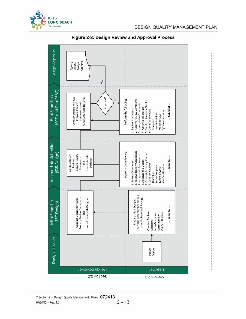
DESIGN QUALITY MANAGEMENT PLAN
7 Section_2_-_Design_Quality_Management_Plan_072413
07/24/13 – Rev. 1.0 2 – 13
Figure 2-3: Design Review and Approval Process

DESIGN QUALITY MANAGEMENT PLAN
7 Section_2_-_Design_Quality_Management_Plan_072413
07/24/13 – Rev. 1.0 2 – 14
2.2.3 Comment, Response and Resolution Process
After the submittal package is sent to the POLB Program Manager, the Program Manager distributes the package and follows the Design Review portion of the process. The Comment, Response & Resolution Log sheet is presented in Figure 2.4.
However, after a predetermined Design Review period, the comments are returned to the Program Managers and Designer from the Design Reviewers, on the Comment, Response and Resolution Log Sheets. Then the Designer will prepare their initial responses and begin resolutions and implementation.
The resolution of comments is a critical step in the design process and requires a thorough evaluation and coordination to completely resolve each comment. The Design Manager will distribute the formal review comments to the appropriate Discipline Leaders. The Discipline Leaders will evaluate the comments and provide an initial response within ten (10) working days of receiving the comments. Meanwhile, the Designer may choose to update the design, if they agree with the comments. However, some comments may require additional coordination in order to achieve a final resolution.
Then the individual Discipline Leaders, whose groups are involved, will coordinate the response among the appropriate stakeholders. The Discipline Leaders, with the Design Manager will hold Comment Resolution Meetings (as needed), and will prepare the initial response to comments. If needed, the meeting should take place within ten (10) working days of receiving the comments.
This response will be sent back to the POLB Program Manager to inform him of the intended action to resolve each particular comment. However, if resolution to the comment cannot be achieved, then the resolution must be elevated to a higher level of management to adjudicate. In this case, the Project Manager, Design Manager, Discipline or Task Leaders, will usually represent the Design Consultant in adjudication along with senior management from the POLB. When time is of the essence, to effectively resolve the comments, all parties should be as efficient as possible. The final resolution of the comments will be documented, incorporated into the design and verified.
Once the formal response to comments has been received, then the responsibility will fall upon the Design Manager to coordinate the comment resolution and implementation activities.
This coordinated activity will be facilitated through comment resolution meetings, as necessary. These meetings will include the appropriate Manager level within the POLB, Design Discipline Leaders and the agency reviewers, as applicable. It is the responsibility of the POLB Program Manager to ensure that the proper level of POLB management participates in the resolution. These coordination meetings will continue until all of the comments are entirely resolved. As progress is being made and these issues are being resolved, it will be communicated and recorded on the Comment, Response & Resolution Log Sheet.

DESIGN QUALITY MANAGEMENT PLAN
7 Section_2_-_Design_Quality_Management_Plan_072413
07/24/13 – Rev. 1.0 2 – 15
The Designer may start the next milestone (50%, 100% or final) and incorporate the resolved comments in accordance with the design requirements at any time and as agreed by the Program Manager. It is important to ensure that the quality records are appropriately maintained by the Designer.
2.2.3.1 Comment, Response and Action Codes
The Design Reviewer will categorize each comment with a Comment Code based on its requirement, as follows:
• E = Design or Engineering • Sp = Specification • CAD = Drafting Standard • G = Suggested, General or Global
The Designer will reply with an initial Comment Code, which may de different than the Reviewer’s Comment Code. The Designer will also state the intended Action Code. The Action Codes are shown, as follows:
• A = Will incorporate • B = Will incorporate in next submittal • C = Continue resolution • D = Adjudication required
This determination may require the Designer to suggest a different Comment Code which is placed on the Comment, Response & Resolution Log Sheet. Generally, the majority of the comments can be easily resolved and require only a brief statement to communicate the resolution of the Designer to the Reviewer. However, some comments will require a much more detailed explanation and meetings to resolve. One or more meetings with the Discipline Leaders and Reviewers may be necessary to resolve some comments. The responses that require adjudication will be resolved jointly between Program Manager, Designer, Design Reviewer Approving Agency, and the possibly client (tenant). The Program Manager is responsible for the adjudication process.
It is considered Best Practice to provide sufficient information in the response column so that the response can be explicitly explained, without leaving any room for interpretation or ambiguity.
For each comment, this process is repeated during each cycle, until approval occurs. After all of the comments have been resolved and verified, then the POLB will issue final approval. The design will then advance to the next phase of project development process, the Bid and Award Phase.
The Design Review and Approval Process Figure 2-3 shows the flow of the activities that occur after the submittal is made by the Designer. This shows how the project advances through the review cycles until it is approved to advance to the Bid and Award Phase

DESIGN QUALITY MANAGEMENT PLAN
7 Section_2_-_Design_Quality_Management_Plan_072413
07/24/13 – Rev. 1.0 2 – 16
Figure 2-4: Comment, Response & Resolution Log Sheet

DESIGN QUALITY MANAGEMENT PLAN
7 Section_2_-_Design_Quality_Management_Plan_072413
07/24/13 – Rev. 1.0 2 – 17
2.3 DOCUMENT MANAGEMENT
The Designer should use an electronic data management system (EDMS), for managing and sharing project files, design files, and quality records. It is most efficient if these files are accessible with an internet connection from anywhere and at any time by the POLB project and quality management staff. These folders should contain the most current scope of work, schedule, quality records (from internal quality reviews), and comments from POLB Design Reviewers.
This type of system will allow for easy access by POLB Program and Quality Management to continuously monitor and audit the progress of design activities, and then produce timely management reports for Senior Port Executives.
A filing system for the quality records must be maintained and transparent to all staff working on the project. The folders reserved for these documents should not encroach or hinder any of the administrative, financial, or design development folders. They should only house quality records.
2.3.1 Quality Records Filing Structure
This section provides an overview of the filing structure that is developed in the EDMS to house the quality records for each submittal package. Within this structure, there are folders that will house the Agency review comments as well as the responses regarding the design.
The deliverables section of the Quality Assurance Plan is placed under the project folder, in a high level folder named Quality Records. This folder houses the quality management activities and their resulting deliverables. These deliverables will conform to the WBS numbering system used in the scope of work and the master schedule.
Each main task folder (and the subfolders for each deliverable and submittal) is created and reserved. These subfolders will house the quality records reviewed by the Design Manager and/or Discipline Leaders.
2.4 QUALITY ASSURANCE PROGRAM
The Design Quality Assurance Program will be implemented throughout the entire Design Phase to assure that the engineering and design deliverables are accomplished in accordance with the Design Quality Management Plan (DQMP) and the contract requirements.
Both the Design Quality Assurance Manager and the POLB Quality Assurance Manager will conduct surveillances and audits on the Designer and his Design Team in accordance with the Port’s Quality Assurance Program. Surveillance and audits will be scheduled and performed at a frequency commensurate with the activities on the project. If deemed necessary, surveillance may be conducted prior to each milestone submittal in order to

DESIGN QUALITY MANAGEMENT PLAN
7 Section_2_-_Design_Quality_Management_Plan_072413
07/24/13 – Rev. 1.0 2 – 18
ensure that the DQMP requirements have been met. Similarly, audits may be performed one or more times depending on the health of the Designer’s Quality Management Program, as determined through the POLBs Quality Assurance Program activities.
2.4.1 Preparing for Audits and Surveillances
The Designer is responsible to complete, maintain and submit to the POLBs Program Manager and Quality Assurance Manager three items approximately three weeks prior to a submittal. These items are:
Itemized Submittal Log: This is a log sheet that lists every item that will be included in the submittal. This should list every sheet grouping, report, calculation set, cost estimate, specifications, reference documents and electronic data, etc.
Quality Control Activity Log: This provides a micro schedule of the QC activities that are completed and/or planned. This should also show the actual schedule for a comparison.
Design Control Log (as required): The intent of this document is to have a tracking log that shows any substantial change that occurs late in the design development process. This should not be implemented too early. After the 100% submittal is usually the best time to start maintaining this document. However, it is at the discretion of the Program Manager.
These log sheets are included in Appendix B.
2.4.2 Accommodating Audits and Surveillances
Surveillances and Audits should not be threatening. They are a method to check the health of the Designer’s DQMP implementation. These can be very helpful to the Designer by providing input on how their program may improve, which will result in improved design documents.
The POLB Quality Assurance Manager will conduct a surveillance to review the Designer’s Quality Program about 7 to 10 days prior to the submittal and again 2 to 3 days prior to the submittal. A meeting at the beginning of the surveillance or audit called an “Entrance Meeting” will be to orient the POLB Quality Assurance Manager to the project and describe how the quality program is implemented. The Project Manager, Design Manager and a few key discipline leaders are expected to attend the meeting. Generally, one resource person is sufficient during the quality review for questions or clarifications.
The Quality Assurance Manager will review the quality records and end the visit with a brief meeting called an “Exit Meeting” to discuss the results. The POLB QM will complete a draft report that is reviewed by the Designer, and a final report that becomes a Quality Assurance record that is distributed to the POLB management staff and the designer. The Project Principal is encouraged to attend the entrance and exit meetings.

DESIGN QUALITY MANAGEMENT PLAN
7 Section_2_-_Design_Quality_Management_Plan_072413
07/24/13 – Rev. 1.0 2 – 19
2.5 TRAINING AND IMPLEMENTATION
The Design Quality Assurance Manager will provide initial training for personnel assigned to the project. Training will consist of orientation for new project personnel, on-the-job training, and formal training. Distribution of training materials and attendance at training sessions will be documented as part of the training program and maintained by the Design QA Manager.
The Designer will inform the Design Quality Assurance Manager of any new staff assigned to the project. The Design Quality Assurance Manager will then provide training on the applicable sections and procedures of the DQMP for the new personnel. This training will introduce them to the quality control procedures in the DQMP that are applicable to their work function.
On-the-job training can be scheduled periodically, as needed, to provide timely instruction related to particular tasks. Both on-the job and formal training shall be provided on an “as-needed” basis and will include the following updates:
• Technical developments • Revisions to the DQMP • Project procedures • Quality record retention
At the discretion of the Design Quality Assurance Manager and the POLB Quality Manager, audit trends or discoveries may also necessitate additional training. Personnel who will perform specific assigned tasks must have the professional qualifications to do so. This should be based upon appropriate levels of education, training, and/or experience (as required).

DESIGN REVIEW PROGRAM
Quality Management System
07/24/13 – Rev. 1.0 3 – 1
3.0 SECTION THREE: DESIGN REVIEW PROGRAM
3.1 INTRODUCTION
The purpose of a Design Review is to identify defects and recommend solutions as early as possible in the design development process. By removing defects early in the process (through the milestone submittals), the review will help prevent defects from propagating through multiple phases of the work products and reduces the overall amount of rework that causes project delays and construction change orders. The cost of correcting a defect increases as it progresses through the project development process. Additional effort spent in the early stages of development to discover and correct errors is therefore worthwhile.
The Design Review Program refers to an External Review done by POLB personnel, or their contractors, which takes place outside of the Design Team’s contractual requirements. It is considered a Quality Control activity, and occurs after the Designer has completed their Internal Review, and has fulfilled all their Design Quality Management Plan (DQMP) requirements (as discussed in Section 2). To maintain independence, it is important to avoid any monetary connection between the Designer and the Design Reviewer.
The Design Review Program described in the following pages uses a “Risk Based” approach, which concentrates the review effort on the higher risk disciplines. The remaining time is distributed across the remaining disciplines of the design. Once the risks are known, then the Design Reviewers will concentrate their work efforts accordingly. The Pareto rule (80/20) applies. In other words, 80 percent of the review effort will focus on 20 percent of the project. So, in order to determine the areas of risk, a risk identification and assessment log for the project must be developed and maintained in accordance with the Project Risk Assessment Manual.
Feedback from the Design Division and the Construction Division on similar projects that have resulted in change orders, schedule delays and cost overruns will help the Project Manager determine the scope of work for the Design Reviewers. In turn, this information allows the Program Manager to request the most efficient and effective review from the Design Reviewer.
3.1.1 Design Review
A Design Review is a milestone review within the design development process, in which a design is evaluated against its requirements. A Design Review is necessary in order to verify the outcome of previous activities; identify issues before committing to a design; and if necessary reprioritize future work. The Design Review team will be comprised of discipline leaders who may be subject matter experts and experienced with a specific type of engineering work.

DESIGN REVIEW PROGRAM
Quality Management System
07/24/13 – Rev. 1.0 3 – 2
The Design Review Program is conducted by POLB discipline leaders and/or subject matter experts. However, the POLB may retain a Design Review Consultant to conduct the design reviews. These professionals should be fluent with the design criteria, standards, specifications and other bid documents and must be capable of quickly spotting design deficiencies, discrepancies, irregular bid items, non-standard features, material options, construction staging, specifications and bid documents. The Design Review team will prepare their specific design review comments on a Comment, Response and Resolution Log Sheet. The team leader will be responsible for collecting the comments and consolidating all of the comments into one MS Excel workbook with a tab for each discipline. The consolidated workbook will then be sent to the POLB Program Manager, who will forward it to the Designer.
A clear distinction between the Peer Review and the Design Review must be understood. In a Peer Review, the reviewers are focused more on a broad evaluation of the design package’s consistency, clear interpretation of the construction and buildability. In addition, a Peer Review is usually limited to no more than six highly qualified individuals, and when completed, a Peer Review will usually result in a report with recommendations.
A Design Review, on the other hand, is divided into a thorough review of each relevant discipline, and their findings are recorded in a Comment, Response and Resolution Log Sheet. Also, in large projects, there would be numerous discipline experts that may be brought in to participate in this review.
The Design Review Program recommends a formal Design Review Process, which may include a wide variety type of reviews from similar items described in a Peer Review but may also include detail discipline “nuts and bolts” type reviews. The reviewers’ comments are made on a Comment, Response and Resolution Log Sheet.
3.2 DESIGN REVIEW PROGRAM
The Design Review Program is a Risk-Based Review, which means that the POLB will define the review type in the most efficient and effective way possible, based on the risks described later in this section.
Specifically, this means that more time and energy will be spent on the higher risk areas of the design package, rather than the low risk areas. The low risk areas are still reviewed, but less time is focused on the low risk areas. However, every area of the design package will be reviewed for consistency, thoroughness and completeness.
The Program Manager will determine the type of review that is appropriate for the project. There are two categories of risk, management and technical. In order to determine the most effective review, the Designer will provide input on the technical risks and Program Manager will assess the management risks. Both categories of risks should be considered as part of the review.

DESIGN REVIEW PROGRAM
Quality Management System
07/24/13 – Rev. 1.0 3 – 3
The Design Reviewer will conduct progressive reviews as determined by the POLB Program Manager and Quality Manager. Engineering design follows the Feasibility/Pre-Design Phase of project development process, and the project definition determined in this phase will establish the starting point for the Design Phase milestone reviews. These review milestones are established and defined as the 15%, 50%, 100% and Final design. Each milestone should be reviewed for different work items as the design advances toward the final construction bid packages. Below are general guidelines that describe the purpose of each Design Review.
• The 15% Design milestone should focus the review on the fundamentals of the project, such as fatal flaws, meeting the project criteria, consistency with the environmental document, and application of engineering judgment and implementation of design criteria. More detailed review includes items such as; alternative analysis, design economy, assumptions, access, layout, adjacent property and facilities impacts, current and future projects, bridge type, construction methods, and the comparison of construction cost to the project budget allocation, etc.
• The 50% Design milestone should verify how the previous review comments were incorporated, and focus the 50% review on more of the engineering design details such as demolition, geometric layout, conflict analysis, traffic circulation, property access, materials and lead times, draft specification, construction staging and schedule, construction cost estimate, etc.
• The 100% Design milestone should verify how the previous review comments were incorporated and focus on the final construction package consistency, risk assessment, constructability, bidability, thoroughness and completeness of the bid package such as the specifications and bid requirements.
• The Final Design represents a package that is ready to advance to the Bid Phase. All required QC and design reviews have been completed and resolved as necessary. The specifications have been reconciled against the quantities and plans.
For architectural projects, please refer to the Architectural & Engineering Guidelines for Building Design Services, Section 7.0:
• The Schematic Design Phase (50% and 100%) focuses on space planning and building systems.
• The Design Development Phase continues to provide more detail information about the building space planning, systems, sustainability and efficiency.
• The Construction Documents Phase (50% and 100%) is the preparation of the detail, drawings, specifications and bid documents necessary to bid the project.
The Program Manager should consider the submittal milestone, determine the management and technical risks, as well as the basis of the review, prior to making the decision on the type of review(s) to request from the Design Reviewers.

DESIGN REVIEW PROGRAM
Quality Management System
07/24/13 – Rev. 1.0 3 – 4
3.2.1 Design Review and Approval Process
Figure 3-1: Design Delivery Process shows the workflow from initiating the Design Phase and approval of the Design Documents. This is broken into two sub processes: 1) Design Development process, which is discussed in Section 2: Design; and 2) Design Review and Approval Process, which is discussed in this section. The Design Review and Approval Process require activities by both the Designer and the Design Reviewer, which are on the right half of this flow chart.
Figure 3-1: Design Delivery Process
DESIGN REVIEW PROGRAM
Quality Management System
07/24/13 – Rev. 1.0 3 – 5
3.2.2 Design Review Methodology
Figure 3-2 shows the Design Review Methodology. The activities that are included in the bottom three swim lanes of this figure are described below. There are eleven (11) activities that take place after the Quality Manager performs the QA Review of the Designer’s package and before the design can advance to the next milestone in the process.
Follow the flow on Figure 3-2, below. Each activity is labeled with a number that corresponds to the description described below:
1. The Design Review Process starts when the Program Manager assesses the project risks with input from the Designer, and the Quality Manager.
2. The Program Manager produces the Design Reviewer’s Scope of Work (approximately 4 weeks in advance) of the actual review.
3. The Designer then submits the Design package. 4. The POLB Program Manager confirms the content and schedule of the submittal. 5. (Optional) The PM holds an orientation meeting with the Designer and the Design
Reviewers prior to the actual review. It is important that the Designer update and submit the Risk Assessment Log (prior to this meeting) so that it can be discussed at this meeting. In addition, this meeting is both the time and the place for the Design Reviewers to ask any other questions that they may have regarding the project.
6. The Design Reviewer performs the design review. 7. As the Design Reviewers perform the design review, they will document and record
their comments on the Comment, Response, and Resolution Log Sheet. 8. Once these comments are recorded, they will be consolidated by the Design
Review Team Leader, and then submitted to the POLB Program Manager. 9. The Program Manager will then review these comments and forward a copy to the
Designer or post them to the Electronic Data Management System. 10. The Designer will review and evaluate each of the comments and then provide an
initial response. 11. The Designer will work with the Program Manager and the Design Reviewers to
develop consensus on the resolution of each comment, and then work to incorporate each resolution into the updated Design Documents. Once this is done, the document set will go on to advance to the next design milestone (50%, 100%, or Final).
This process continues until each design milestone has been completed and the document is submitted to the agency for approval. The ultimate objective of the comment, resolution and implementation process is to completely resolve all comments to an agreed level of consensus, without leaving any comments unresolved.
The Designer will be responsible for implementing the resolution for each comment. However, it will be the Design Reviewers who check their work and actually verify that these resolutions have been incorporated into the design documents.

DESIGN REVIEW PROGRAM
Quality Management System
07/24/13 – Rev.1. 0 3 – 6
Figure 3-2: Design Review Methodology

DESIGN REVIEW PROGRAM
Quality Management System
07/24/13 – Rev.1.0 3 – 7
3.2.3 Project Risk Assessment (Activity 1)
To establish the Scope of Work for the Design Review, the Design Reviewer’s Scope of Work form will be used to evaluate the risks of project management elements that interfere with quality. The form is shown below for reference. The technical risks should be considered using the Project Risk Assessment Manual and the Risk Assessment Log.
Figure 3-3a: Design Reviewer’s Scope of Work Form (Page 1 of 2)

DESIGN REVIEW PROGRAM
Quality Management System
07/24/13 – Rev.1.0 3 – 8
Figure 3-3b: Design Reviewer’s Scope of Work Form (Page 2 of 2)
The form is broken into four parts. The first is labeled “I – Assessment of Designer” and it provides a table for describing the Design Management Risk. The left column lists the critical management elements that can interfere with quality. Across the header is the risk area, a brief description of the risk, and the estimated level of risks. Only one level of risk should be noted for each risk area. When this table is properly completed, the Program

DESIGN REVIEW PROGRAM
Quality Management System
07/24/13 – Rev.1.0 3 – 9
Manager will see how critical the management aspects may contribute to quality, which will help determine if an outside Design Review is necessary.
3.2.3.1 Scope of Work for Design Reviewer (Activity 2)
Part I of the Design Reviewer’s Scope of Work Form should be updated at least four weeks prior to a submittal at each Design Review milestone (i.e. 15%, 50%, 100%, Final).
The POLB Program Manager, along with the tenant (customer) should determine the design requirements early in the design development process. This information should be included in the Design Reviewer’s scope of work and serve as a fundamental piece in determining the Design Reviewer’s requirements. Additional items can be added, as necessary. Part III of the form labeled “Scope of Work Items”, provides a table for this process. The purpose of this table is to provide direction to the Design Review Team on what they should be reviewing.
3.2.3.2 Design Review Technical Considerations
The design begins by establishing or confirming the existing site conditions and completing additional field investigation as necessary to have sufficient information to start the design. The first step is to develop the geometry and site layout, alignment, building locations, etc. that meet the purpose of the project. Therefore, the design review for the 15% design should focus on the fundamental technical direction of the project. Later milestones will build on these fundamentals and focus more on the consistency, conflict analysis, specifications, and finally the bid package. Part IV of the formlabeled “Critical Disciplines of Work to Review”, provides a table that shows some of the items that would be part of the primary interest in a review for various design milestones. This table is not all inclusive; however, it will provide some direction where the Design Review efforts should be focused. In all cases, the design should be reviewed completely, unless directed otherwise in the scope of work.
3.2.3.3 Types of Design Reviews to Consider Part II of the form labeled “Type of Review”, provides a table for selecting the type of review appropriate for the project. The type of review is based on the management factors that can influence quality as determined in Section 1 of the form. The Program Manager is responsible for determining the type of review that is appropriate for the project.
There are eight types of Design Reviews that fall into two categories and any may be applicable for any project for any particular milestone during the design process. Some of these reviews are required during the Designer’s QC (Internal Review), however, it is acceptable to duplicate this effort based on the available information. These reviews are listed below:

DESIGN REVIEW PROGRAM
Quality Management System
07/24/13 – Rev.1.0 3 – 10
Internal Review (Designer)
• Accuracy Checks are a review of calculations. Results of review are compared with published documents (i.e. drawings) to ensure accuracy.
• Discipline Review is a review of a single discipline of work. This must be performed by the Designer, but also may be performed by the Design Reviewer, if the Program Manager has supporting reasons to do so. Peer Review, described earlier, has been completely replaced in this overall Design Review Process by a more formalized and thorough Discipline Review.
• Inter-Discipline Review (IDR) is a review conducted by Discipline Leaders from a variety of disciplines that have the potential to conflict with one another. IDRs must be performed by the Designer, but also may be performed by the Design Reviewer, if the Program Manager has supporting reasons to do so.
External Review (Design Reviewers)
• Independent Review is a review by an independent and well qualified team of professionals who review the design in an effort to verify that the design criteria, standards, directives, CADD requirements, and specifications are consistently applied throughout the design package. They also review for potential conflicts between all disciplines of work for consistency of work elements, interpretation of the design, etc. In addition, they provide suggestions that may improve the design. This review is dependent on others to perform the actual engineering analysis and design.
• Independent Analysis is when a review of the entire design is prepared independently of those who originated the design. This is common practice with structural engineering. The original designer prepares the calculations, analysis and design drawings but only the design drawings are provided to the reviewer. This forces the reviewer to conduct their own analysis of the design. This process is also used with quantities and cost estimates.
• Value Engineering Study is when the design is reviewed for cost saving opportunities. Value engineering offers the most economic value during the pre-design phase. This is when major management decisions are being made on high cost items such as two tracks versus three tracks, or grade separation of an intersection versus an at-grade intersection. Value engineering studies performed later during the design phase may focus more on material availability and costs to install. There is still an economic value to these later studies; however, the largest savings usually come from the reduction in the construction schedule.
• Constructability Review is performed to ensure that work elements can be constructed without interference, conflict, sequence or potential interference. If there is the possibility of interference, then it needs to be mitigated. Constructability Reviews should be performed by the Designer, but also may be performed by the Design Reviewer, if the Program Manager has supporting reasons to do so.

DESIGN REVIEW PROGRAM
Quality Management System
07/24/13 – Rev.1.0 3 – 11
• Bidability Review is performed to verify that the bid documents are complete, thorough, and properly referenced between all of the bid items throughout all bid documents.
The type and level of the Design Review is determined by the responsible POLB Program Manager. ‘Best practice’ suggests that a design review occur at each design milestone (15%, 50%, 100%, and Final), especially for larger and complex projects. However, for smaller and simpler projects, following ‘best practice’ may not be necessary.
At each milestone, the Design Review should focus on different project design elements. For example, the 15% Design Review should focus on the project footprint and fundamental engineering components, such as geometric alignment, bridge types, access, minimizing right-of-way impacts, engineering economics, etc. For later design milestones, the focus should be on the details, quantities, specifications, cross references between disciplines of work, constructability, bidability, etc.
Each Design Review Cycle follows the same general process. However, there are slight differences in each that are unique to that particular milestone. The top of Figure 3-2, shows a flowchart that specifically depicts the overall Design Review Cycle.
Each Milestone of the Design Review Cycle fundamentally consists of two parts: The Design Review Program and Comment Resolution. These are discussed below.
3.2.3.4 Design Reviewer’s Qualifications
The Reviewer’s shall have the education, professional credentials and a minimum level of experience commensurate with the size and complexity of the review assignment. Resumes of the Design Reviewers shall be provided to the Program Manager and Quality Manager for review and approval prior to the review taking place.
3.2.4 Designer Submits Package to POLB Program Manager (Activity 3)
There should be absolutely no ambiguity regarding the content of the submittal package and what will be expected from the Designer at each Design Milestone (15%, 50%, 100% and Final). For this reason, it is clearly stated below:
First, the submittal package should contain the drawings, reports, specifications and calculations that support the Design.
Second, it should contain the checklist of assumptions, and other materials that make up the Basis of Design.
Third, it should consist of the updated Risk Register that has been prepared by the Designer. As discussed earlier, the Risk Register is used by both the Program Manager and the Design Reviewer to determine the level of effort that should be placed on various parts of the design.

DESIGN REVIEW PROGRAM
Quality Management System
07/24/13 – Rev.1.0 3 – 12
3.2.4.1 Designer’s Responsibility Prior to a Submittal
The Designer’s Quality Control review, discussed in Section Two, is conducted by the Designer’s organization. It is important to note that the Design Quality Management Plan (DQMP) is prepared by the Designer and submitted to the POLB Quality Assurance Manager and the POLB QOT (Quality Oversight Team) for approval within 30 days of Notice-to-Proceed.
Later, during the design process, the Designer is expected to follow the processes and procedures that were documented in their (approved) Design Quality Management Plan (DQMP). The DQMP should also address the basis of the design, as well as the design requirements.
Both the Designer’s internal Quality Assurance Manager and Project Manager must sign off on a Quality Management Certificate that attests to the fact that the design package is in full compliance with the approved DQMP. The Quality Assurance Certification will be submitted along with each design milestone (at 15%, 50%, 100%, and Final).
The purpose of this certification is to verify that the Designer has properly conducted the Quality Control (QC) and Quality Assurance processes and procedures as required for the submittal package. The Designer’s QC is a critical and fundamental component of the Quality Control Process and it cannot be skipped or compromised. Once the Designer has demonstrated to the Program Manager that their organization is in compliance with the DQMP, then it is ready to progress to the next step in the Design Review Program.
3.2.5 Program Manager Confirms Submittal Package (Activity 4)
Once the Program Manager receives the package from the Designer, and before the package can be formally accepted, the Designer will confirm that the following items are actually in place and a part of the submittal package:
1. The Quality Assurance Certificate with signatures from the Designer’s Quality Assurance Manager, and the Designer’s PM
2. The package of drawings, calculations, reports, specifications 3. The Risk Assessment Log 4. The Itemized Submittal list 5. The QC Activity Schedule 6. The Design Control Log (when applicable) 7. The Comment, Response and Resolution Log
Any schedule delays that are due to incompleteness of the package are the responsibility of the Designer.
Once a complete milestone submittal review package has been received by the Program Manager the PM will be able to move to the next step in the process, and set up an optional orientation meeting between the Design Team and the Design Reviewers.

DESIGN REVIEW PROGRAM
Quality Management System
07/24/13 – Rev.1.0 3 – 13
3.2.6 Optional Orientation Meeting (Activity 5)
Prior to the Design Review starting, the POLB Program Manager may choose to hold an orientation meeting to assist the Design Review Team. The intention of this meeting is to help the Design Review Team quickly get “up to speed” on the project purpose and ultimate objectives of the design to be constructed. This is an optional meeting that is held at the discretion of the Program Manager.
3.2.7 Design Reviewers Conduct Reviews (Activity 6)
Once the designer’s orientation meeting has been completed, each Design Reviewer should be expected to diligently and conscientiously review the package of material that has been provided. Each Design Reviewer should conduct the review according to the requirements specifically stated in the Design Review Scope of Work.
3.2.8 Documenting Review Comments (Activity 7)
One very critical part of the Design Review Process is to have each Design Reviewer, regardless of their physical location or discipline of work, use the same standard Comment, Response, and Resolution Log Sheet to document their comments. See Figure 3-4 for the required form.
3.2.9 Consolidate Review Comments (Activity 8)
The Design Review Team Leader shall be responsible for consolidating the review comments into one Comment, Response and Resolution Log Sheet.
For consistency and good quality practice, all comments should be generated in the same format, with the same required fields of information. All comments should then be centralized into a single MS Excel workbook, and each discipline reviewer will place their comments on a single spreadsheet in the workbook. The spreadsheet tabs should identify the discipline.
3.2.10 Program Manager Reviews Comments (Activity 9)
Once the comments have been consolidated, the Design Reviewers will forward the comments to the Program Manager. The Program Manager will then review the comments so that he has a working understanding of the issues and matters that need to be resolved. After this occurs, he will then forward the comments to the Designer or post them on the Electronic Data Management System.
3.2.11 Designer Evaluates and Provides Initial Response (Activity 10)
The resolution of comments requires that the Designer review the comments and compare them to the actual design document, prior to making a response. The Designer may then agree, disagree, or require further clarification regarding any of the comments.
Generally, only the comments in which there is a disagreement, or in which there may need to be some clarification, will require a meeting to resolve. When this occurs, a joint
DESIGN REVIEW PROGRAM
Quality Management System
07/24/13 – Rev.1.0 3 – 14
resolution meeting should take place between the Program Manager, Designer and Design Reviewers. It often needs to be performed discipline by discipline.
Sometimes, the POLB Senior Management must be engaged to adequately and timely resolve the comments. It is the responsibility of the Program Manager to assess this need and be certain that the right people are involved in the resolution process.
3.2.12 Comment Resolution and Implementation (Activity 11)
Once a solution or resolution is identified, then it is the responsibility of the Designer to implement the resolution. However, sometimes the resolution may be delayed due to uncontrollable circumstances, and may not get implemented until after the next milestone submittal. This should be tracked on the Comment, Response and Resolution Log Sheet.
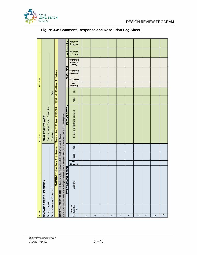
DESIGN REVIEW PROGRAM
Quality Management System
07/24/13 – Rev.1.0 3 – 15
Figure 3-4: Comment, Response and Resolution Log Sheet

DESIGN REVIEW PROGRAM
Quality Management System
07/24/13 – Rev.1.0 3 – 16
3.3 METRICS OBTAINED FROM THE DESIGN REVIEW
Metrics can be collected from at multiple points during the design process. These are management and technical metrics which is discussed in more detail in Section Four: Quality Assurance Program of the QMS. The following describes some indicators of technical quality and performance of the Designer and Design Reviewer.
Designer: A preliminary indication of technical excellence will result from the comments noted in the Comment, Response & Resolution Log sheet. Comments made due to design criteria, design standards, specifications, design directives and CADD requirements not met are indicators of less than desirable quality. Comments made on constructability, safety or bidability may also be indicator of quality. However, these comments must be accepted and proven in order to have a final assessment of technical performance.
Design Reviewer: The quality of the comments can be determined from the responses to the comments from the Designer and the final resolutions of the comments. If there is little opposition from the comments, and the resolutions hold in favor of the Design Reviewer, then the quality of the comments are desirable and demonstrates a satisfactory quality review. If the suggested (or preferences) comments add good value to the economy of the design, then this indicates a satisfactory quality result. However, if the majority of the comments are resolved in favor of the Designer, then the quality of the Design Reviewer’s comments are less than desirable.
3.4 SUMMARY
This Section of the QMS provides guidance for the Program Manager in determining how to establish an efficient and effective Design Review Team (Design Reviewer). The program suggests a “Risk Based Review” approach, which identifies and evaluates the risks, and focuses the majority of the review effort on the higher and medium risk discipline of work.
This program also suggests that the majority of the review is based on the requirements, and less emphasis on suggestions. Suggestions should be based on sound economical engineering judgment opposed to preferences. The Comment, Response & Resolution Log Sheet, provided within, helps curtail this while enforcing resolution of comments and verification of implementation into the updated design documents.
This Design Review Program is expected to get improved results from the Design Review Team and Designer, but requires buy-in and delegation by the Program Manager, and enforcement by the Quality Oversight Team.

QUALITY ASSURANCE PROGRAM
Quality Management System
07/24/13 – Rev. 1.0 4 – 1
4.0 SECTION FOUR: QUALITY ASSURANCE PROGRAM
4.1 INTRODUCTION
This section discusses why a quality assurance program is critical to continuous improvement and how this program can measure performance. There are two types of quality programs: Reactive (static) and Proactive (dynamic). A reactive quality program is only a quality control program, which can be formal or informal. The POLB contract requires that a designer have a quality management plan, therefore the program is formal. If no monitoring is taking place then the program is static, which provides little opportunity to improve over time. However, a robust quality program requires monitoring, which allows a quality program the opportunity to continually improve.
A Quality Program must have a monitoring process or oversight to ensure compliance and conformance; this is referred to as Quality Assurance (QA). A Quality Assurance Program establishes the oversight requirements that are applied by a Quality Assurance Manager (QAM) in order to maintain a robust and healthy program. The Quality Assurance Manager has the responsibility to manage the overall program; monitor the implementation of the program for both internal users (Program Managers) and external users (other departments and consultants); assess the health of the program; identify areas of improvement; continually improve the program; prepare and distribute lessons learned; and report on the health of the program to the senior management.
A Quality Assurance Program provides the opportunity to capture metrics through quality reviews such as surveillances and audits. As metrics are collected over time, not only can the program continually improve, but the performance can be measured. The Quality Assurance Program discussed within is a robust program that requires an active Quality Assurance Manager to identify deficiencies, inform the Program Managers and assist with corrective action.
4.1.1 Quality Assurance Management
There are up to three levels of Quality Assurance Management and the highest level is the POLB Quality Assurance Manager followed by the Consultant’s Quality Assurance Manager and if they have subconsultants, they may also have a Quality Assurance Manager. Figure 4-1: Quality Organizational Chart shows these levels of Quality Assurance. The Designer and Design Reviewer will assign a Quality Assurance Manager to a specific project and within their department or consulting firm. The Designer generally has subconsultants, who should have a Quality Assurance Manager within their organization. However, the prime consultant has the ultimate responsibility for ensuring the subconsultants are conforming and are in compliance with the approved Design Quality Management Plan (DQMP). Some

QUALITY ASSURANCE PROGRAM
Quality Management System
07/24/13 – Rev. 1.0 4 – 2
organizations hire independent auditors to review their Quality Program periodically; this is another quality assurance activity.
Figure 4-1: Quality Organizational Chart
4.1.2 Roles and Responsibilities
POLB Quality Assurance Manager
The POLB Quality Assurance Manager has the responsibility for planning, monitoring, reporting and updating the Quality Assurance Program; reviewing and approving the Designer’s DQMP; implementing and training the QMS; monitoring the Program Managers, Designers and Design Reviewers for compliance and conformance.
Designer Quality Assurance Manager (Prime Consultant) The Designer’s Quality Assurance Manager has the responsibility for preparing a DQMP, monitoring the prime and subconsultants, reporting quality issues to executive management and Project Management within the firm; and cooperating with the POLB surveillance and audit requirements. Design Reviewer Quality Assurance Manager The Design Reviewer’s Quality Assurance Manager has the responsibility for preparing a Design Review Quality Management Plan; monitoring the prime and subconsultants for compliance and conformance; reporting quality issues to executive management and Project Management within the firm; and cooperating with the POLB surveillance and audit requirements. Subconsultant Quality Assurance Manager The Designer’s Subconsultant Quality Assurance Manager has the responsibility for preparing a DQMP or enforcing the Prime consultants DQMP; monitoring the

QUALITY ASSURANCE PROGRAM
Quality Management System
07/24/13 – Rev. 1.0 4 – 3
subconsultant’s staff compliance, reporting quality issues to executive management and Project Management within the firm; and cooperating with the POLB surveillance and audit requirements.
4.1.3 Best Practices
A robust quality program will ensure program conformance and compliance through a process that identifies deficiencies; methods for corrective action; meaningful performance metrics; continues improvement; and communication for lessons learned is essential for best practice. A robust program will also clearly show the year after year performance.
4.1.4 Goals and Objectives
The Quality Management System is a tool that assists the POLB to identify deficiencies and quickly corrects those deficiencies in an effort to reduce and minimize construction cost overruns and schedule delays due to avoidable errors.
4.2 PROGRAM OVERVIEW
The POLB has effectively delivered marine, site, architectural and freight rail projects with efficient project management, and it has clearly shown that it is a good steward of public funds. However, to meet the quality objectives, the POLB management has improved their quality program to help ensure a higher level of efficiency and effectiveness and continuous improvement.
The Quality Assurance program will measure project performance, and the performance of Designers and Design Reviewers, across a diverse set of infrastructure projects, by using a consistent set of metrics. Each project varies in size, scope and complexity. However, a standard set of metrics that can be used on any project, so this quality program can provide a direct comparison between projects and a performance measure can be produced.
Once the metrics have been recorded, then an accurate baseline can be determined. If sufficient historical data (5 to 10 years) is available such as: planned versus actual; schedule; budget; addendums; change orders; etc., it may be used to establish a baseline performance level. This baseline performance would provide a comparison of the metrics collected from current projects within the first year. Also, this provides the information to better evaluate the performance of the Designer, regardless of the type of project. In addition, by collecting these metrics, and by having this baseline data available, the Quality Assurance Program will have the data to improve their management of project delivery and more consistently reduce construction cost overruns and schedule delays due to design errors and omissions.
Figure 4-2: Quality Assurance and Continuous Improvement Program, provides an overview of this entire Quality Assurance process from the procurement of planning and design professional services through construction.

QUALITY ASSURANCE PROGRAM
Quality Management System
07/24/13 – Rev. 1.0 4 – 4
Figure 4-2: Quality Assurance and Continuous Improvement Program

QUALITY ASSURANCE PROGRAM
Quality Management System
07/24/13 – Rev. 1.0 4 – 5
4.2.1 Program Principles
The Quality Assurance and Continuous Improvement Process is based on the following principles:
1. Downstream processes are highly dependent upon the results from their upstream processes.
2. Undetected mistakes in upstream processes will become more serious problems downstream.
Note: As a result, the earlier we detect a problem, the less time and money it will cost to
correct. Therefore, the goal is first to minimize errors, and then second, to identify and
correct errors as early as possible. Every day saved from delay saves project costs.
3. Certain key metrics can be used as a leading indicator of deeper underlying problems. These metrics are highly correlated with design and construction cost overruns, and are therefore important to record and monitor.
4. The number of Non-Conforming products and Non-Compliant personnel are examples of key metrics that should be tracked because they are highly correlated with cost overruns. These metrics should be tracked and monitored throughout the Project Delivery Process.
5. Monitoring the process for these key metrics will pay for itself many times over in savings from design and construction cost overruns and schedule delays. Historical evidence indicates that a dedicated quality program will save more than it costs. In fact, it will pay for itself many times over by consistently saving (and preventing) cost overruns and schedule delays. In addition, if a potential problem does exist, then the earlier in the project development cycle that it is discovered and addressed, the less it will cost to address or remediate.
4.2.2 Quality Assurance and Continuous Improvement Program
The Quality Assurance Program is implemented throughout the entire program of projects to ensure that the design deliverables are systematically checked and reviewed in accordance with an approved Design Quality Management Plan implemented by the Designer. The Quality Assurance Program refers to tasks that are completed in order to finalize a deliverable product (source). The source is reviewed by the POLB Quality Assurance Manager to determine if it is in conformance and compliance with the Quality Program and the results are noted. This provides the necessary information to obtain metrics that lead to performance indicators. At this time, the focus is specifically on the Design process. However, the QA process is very similar for each phase of the project development process.
The Design column, for example, provides three sub columns: Tasks, Source and Metrics.
Tasks: A list of work tasks that are commonly included in the contract requirements. For final design these generally include tasks for field investigation, Preliminary Engineering, adjacent property impacts, utility matrix, calculations, drawings, reports, specifications, quantity and cost estimates, and files.
QUALITY ASSURANCE PROGRAM
Quality Management System
07/24/13 – Rev. 1.0 4 – 6
Source: The task information is used to compile a deliverable which is the source product. In final design these would be the milestone submittal documents like the 15% Design, 50% PS&E, 100% PS&E, Final PS&E, etc. The quality records used to accomplish the deliverables are the products that are reviewed by the Quality Auditor and measured against the DQMP. Key metrics are captured by surveillances and audits which are used to determine the performance indicators.
Metrics: Products are prepared in accordance with design criteria, design standards, CAD standards, specifications and directives and these are measured for conformance against the DQMP requirements for verifying work accuracy. Management is measured against compliance of the DQMP requirements. Audit checklists are used consistently from project to project in order to equally identify deficiencies. The results of surveillances and audits are recorded in a report that provides the details which lead to the performance indicators. The performance indicators are reported on a dashboard for a top level review of the overall performance.
The results of the quality assurance work effort provide an indicator of quality performance which is a leading indicator. The Quality Assurance Managers should become very sensitive to leading indicator, as they may lead to significant problems later. The goal of the QA Program is to provide leading indicator information so management can implement a corrective and preventive action plan that prevents small issues from growing to large costly issues later.
4.2.3 Develop Quality Management Plan
After the POLB issues a Notice-to-Proceed, the Design work will begin. One of the Designer’s early tasks is to prepare a Quality Management Plan that meets a minimum threshold of requirements which are common practice in the California design architecture and engineering community. The POLB Quality Assurance Manager will review, comment, work with the Designer to resolve comments and eventually approve the Designer’s DQMP. The DQMP becomes the basis for the surveillances and audits in determining if the designer is in conformance and compliance.
4.2.4 Implementation
It is the responsibility of the Designer to implement the DQMP throughout the entire design team. Implementation is relatively simple if all of the work is being performed in one location. However, this is not very common and the Designers may face challenges when work is performed in multiple offices. This is especially true when the divisions of critical discipline of work tasks are produced in remote offices.
The POLB QA Manager has the responsibility to inform the Program Manager and QOT how well the Designer’s QMP is implemented. This is accomplished by conducting office visits and observing how well the Design Team understands the QMP and their respective responsibilities.

QUALITY ASSURANCE PROGRAM
Quality Management System
07/24/13 – Rev. 1.0 4 – 7
For successful implementation, the Designer must implement the program from Top-Down. A leading indicator is how well does the Design Project Manager understand the DQMP and articulate the program procedures and roles and responsibilities.
4.2.5 Program Monitoring
The POLB QA Manager is responsible for reporting the health of the Quality Program for each project to the Senior Management and Program Managers. They will observe the Quality Control practices performed by the Designer; conduct surveillances and audits in accordance with the Quality Assurance Program; request a corrective action plan from the Designer to maintain the quality requirements; Issue non-compliance or non-conformance reports; conduct root cause analysis as necessary to help determine the best corrective action; follow up and close out audits.
Surveillances and audits are scheduled and performed at a frequency commensurate with the activities on the project. Surveillances are conducted prior to a milestone submittal to ensure that the DQMP requirements are performed. Audits are performed after the submittal and are required, at a minimum, one time per year, but audits may be necessary more frequently depending on the historical performance of the Designer and at the discretion of the Program Manager and Quality Assurance Manager. Surveillances and audits are required to ensure compliance with the DQMP and should be recognized as helpful tools to maintain the highest quality deliverables.
Figure 4-3: QA Program Monitoring provides a flowchart of activities that the POLB Program Manager and QA Manager perform, and the activities that the Designer performs. The following description of activities follows the flowchart:
1. Notice to Proceed (NTP): The Program Manager formally notifies the Designer to proceed with the design.
2. Develop DQMP: the Designer prepares a DQMP specifically for the contracted scope of work and project.
3. Submit to POLB: The Designer submits the DQMP to the POLB for review, comments and approval.
4. QAM Reviews: The POLB QAM review the Designer’s DQMP and works with the Designer as necessary to complete an approved DQMP.
5. QAM Develops Surveillance/Audit Checklists: The QAM prepares surveillance and audit checklists that will be used in audits.
6. Conduct Surveillance/Audits: The POLB QAM coordinates and conducts surveillance and audits of the management and technical work products
7. Prepare Draft Report: The POLB QAM prepares a Draft surveillance or audit report that notes any deficiencies found, and determine the performance indicators.
8. Review Report with Program Manager and Designer: The Draft surveillance or audit report is forwarded to the POLB PM and Consultant Designer PM for review and comment. Any comments are resolved.

QUALITY ASSURANCE PROGRAM
Quality Management System
07/24/13 – Rev. 1.0 4 – 8
9. Complete Final Report: The POLB QAM finalizes the surveillance or audit report and distributes it to the Senior Management (QOT), Program Managers, and Designer’s PM.
10. Complete Follow-up Actions as Necessary: If corrective action is required, the Designer’s PM will address the corrective action in the stated timeframe.
11. Continue Monitoring: The POLB QAM continues to monitor the performance of the Designer.

QUALITY ASSURANCE PROGRAM
Quality Management System
07/24/13 – Rev. 1.0 4 – 9
Figure 4-3: Quality Assurance Program Monitoring
QUALITY ASSURANCE PROGRAM
Quality Management System
07/24/13 – Rev. 1.0 4 – 10
4.3 POST DESIGN QUALITY ASSURANCE ACTIVITIES
4.3.1 Bid & Award
Once the design documents are approved and the project advances to the Bid & Award phase of the project delivery process, performance metrics are collected using the same methodology, only the deliverables are different. Performance metrics collected during Bid & Award are the number of bid inquiries; number of addendums issued; number of bids and bid spread; bids verses the engineer’s estimate, etc.
The data collection of this information is the responsibility of the QA Manager and this information should be provided in the monthly report to the QOT. At some point, it will become evident where the issues are and then the QA Manager can work in collaboration with the QOT and Program Manager to determine how to mitigate the conditions. Sometimes, a root cause analysis is necessary to actually determine why the issue occurring or reoccurring. Once this is know a corrective action plan would be prepared, implemented and monitored.
4.3.2 Construction
The quality of the design of an infrastructure facility is tested during construction. There is no opportunity for beta testing. This is why managing a robust quality program is so critical through the design process in order to minimize construction cost overruns and schedule delays.
Generally, early in construction, the majority of design issues surface. These are items like quantity busts, design errors, design omissions and constructability issues. The construction manager will submit requests for information (RFIs) which lead to design clarifications and design revisions that often result in construction change orders (CCOs).
Cooperation between the Design, Construction and Program Management Divisions becomes very important in order to help the designers improve their design product. A feedback loop distribution of lessons learned to all designers is important to maximize the benefits of a Quality Assurance Program. Each division has responsibilities.
Design Division: The Design Division has the responsibility for maintaining the design standards and design criteria. The design issues that are resolved during construction may lead to a revision of the design standards or design criteria. A feedback loop of lessons learned should be ongoing in order to inform those who can best utilize the information in the best interest of the POLB.
Construction Division: When the contractor raises design issues, time is of the essence to resolve the issues so that the schedule is not delayed. The Designer should quickly address and resolve the issues. This resolution can be of substantial value in order to help prevent reoccurrence of similar design issues on other projects. A feedback loop of lessons learned should be ongoing in order to inform those who can best utilize the information in the best interest of the POLB.

QUALITY ASSURANCE PROGRAM
Quality Management System
07/24/13 – Rev. 1.0 4 – 11
Program Management Division: The Program Management Division’s Quality Assurance Manager is engaged with numerous Designers on numerous projects and has the exposure and network to messenger these lessons learned to the designers. A feedback loop of lessons learned should be ongoing in order to inform those who can best utilize the information in the best interest of the POLB.
4.4 THE ROLE OF QUALITY
The role of quality is to get the project off to a good start and maintain a healthy program. This can be accomplished by clearly and specifically defining the requirements, scope of work, and deliverables. Also, all questions regarding the same should be clearly answered and posted to all respondents in a timely manner.
Indicators of Quality
Indicators of quality, also known as Key Performance Indicators (KPI’s), are demonstrated in metrics that show a low number of questions regarding the scope of work, deliverables, and the RFP. In addition, there should be metrics that reflect a quick turn-around time for the organization to respond to questions. Other indicators of quality will be metrics that show a large number of qualified respondents and a low number of addendums to the RFP.
Frequently, the KPI’s have strong influence over the Critical Success Factors (CSFs). CSFs are simply those metrics that are Critical to the Success of the project. Since the goal of this program is to consistently reduce issues that lead to cost overruns, one requirement for a CSF metric is to define the criteria for success in clear, measurable, and quantifiable terms. Then, as long as the project meets these measurable criteria, it will be an unambiguous success.
Below is a list of the KPI and CSF metrics that may be collected during the Design phase. It is important to note that an increase in non-conforming products or non-compliant personnel may trigger a Quality Audit. This is because there is a very high correlation between non-conforming products or non-compliant personnel and schedule delays and project cost overruns. The performances metrics that add value and collect through surveillances and audits during the Final Design phase:
a. The Project Budget in dollars (target vs. latest estimate vs. actual) b. The Design Schedule in days (target vs. latest estimate vs. actual) c. The number of comments (by category) in each review cycle d. Changes from the original Scope of Work e. The number of non-conformance responses f. The number of non-compliant personnel g. Overall Management and Coordination (qualitative measures)

QUALITY ASSURANCE PROGRAM
Quality Management System
07/24/13 – Rev. 1.0 4 – 12
4.5 GATE REVIEW
A Gate Review is conducted by executive management (QOT) who reviews the work products in an effort to concur that the project is ready to advance to the next phase of project development. Effectively, the QOT will conduct three or more Gate Reviews for each project. These should occur:
prior to advancing to Design; prior to advancing to the Bid & Award process; and prior to releasing the project to the Construction Division.
Only when the QOT agrees that the project has completed all of its requirements should it advance to the next phase of project development.
4.6 REPORTING
The Quality Assurance Manager will prepare a monthly report and submit the report to the Division Director and Deputy Directors within one week of the ending period. The monthly report should note the activities that took place during the past period, emphasis critical quality issues and forecast upcoming activities.
Each year the Quality Assurance Manager will prepare an annual report that evaluates the Program Management Division performance and continuous improvement. Each quarter a quality issues meeting should be held with Senior Management and Program Managers to have an open discussion on the quality goals, the health of the program, to share ideas for improvements and emphasis quality focus areas.
4.7 TRAINING
The Quality Assurance Manager will provide the initial training for the QOT, Program Managers and administrative personnel. Training will consist of orientation for new project personnel, on-the-job training, and formal training. Distribution of training materials and attendance at training sessions will be documented as part of the training program and maintained by the QA Manager.
Training is discussed in more detail in a separate Implementation Plan.

INTEGRATION
Quality Management System
07/24/13 – Rev.1.0 5 – 1
5.0 SECTION FIVE: INTEGRATION
5.1 INTRODUCTION
The Program Management Division of the Port of Long Beach (POLB) has a Project Delivery Manual (PDM) which serves as the primary outline, description, and functional backbone of the POLB project delivery process. The revision date of this document is dated April 1, 2010.
There are three other documents that must integrate with the PDM to form a complete set of policies, procedures, and guidelines regarding this project delivery process. They are:
1. the Quality Management System (QMS) [draft date of December 2012] 2. the Guidelines to Professional Consulting Services (PCS) [revision date of March
2012] 3. the Risk Assessment Manual (RAM) [revision date of November 2012 draft]
To provide a quick review and identification of the integration points between these four documents, these processes are graphically represented in the pages that follow. Each phase (or major milestone event) graphically represents how these four documents, and their corresponding processes, flow and interact with each other.
The following 10 flowcharts present the four documents in a horizontal swim lane format, their corresponding process tasks, and a parallel view of what must be done at each phase, and in roughly corresponding timeframes. In an effort to be clear, each document (and its corresponding process) is represented by a swim lane. The top swim lane in each chart contains the major process steps from the PDM, or Project Delivery Manual.
The second swim lane shows the flow of the Risk Assessment Manual (or RAM). In each chart, this swim lane demonstrates the major process steps that are required in the Risk Assessment Manual.
The third swim lane from the top shows the major process steps that are described in the Guidelines to Professional Consulting Services document (or PCS).
The fourth swim lane is the Quality Management System (or QMS). The major process steps described in the QMS can be seen in this swim lane.
The top swim lane on each page is always the Project Delivery Manual (PDM). The other three documents represent supportive systems, and connect to the PDM at various places. However, the PDM will always remain the central document, and the backbone of the project delivery process.

INTEGRATION
Quality Management System
07/24/13 – Rev.1.0 5 – 2
In the top swim lane of each flowchart, one of the boxes is highlighted in yellow, with the outline of the process box framed in red. This indicates which phase is being depicted graphically on that flowchart.
To emphasize this point, whenever a step in the Project Delivery Process has an integration point with one or more of the other processes, it is highlighted in a blue frame. Managers can use these flowcharts as a reference tool, and can easily check (at a high level) to make sure that all the supporting and integrating processes for that stage in the PDM have been completed.
5.1.1 Integration Flowcharts
1. The first integration flowchart, shown in Figure 5-1, represents the Master Planning Phase of the project delivery process. The reader will notice that there are a significant number of integration points between the PDM and the Risk Assessment Manual (RAM Document). Also notice that this is a good place to incorporate feedback of ‘lessons learned’ from previous projects.
2. The second integration flowchart, shown in Figure 5-2, depicts the integration points between the four documents during the Project Initiation Phase. There is a significant number of tasks associated with risk assessment that are found in the RAM document. In the PCS guidelines, funding sources need to be considered for the Designer selection process. The consultant needs to write and tailor the Project Management Plan. In terms of quality, the selection of a consultant needs to consider the quality requirements of the project, and once selected, a contractor will need to write the DQMP.
3. The third integration flowchart, shown in Figure 5-3, depicts the integration points between the four documents during the Feasibility/Pre-design phase. The majority of integration points in this phase are related to the PCS guidelines document. In this phase, the consultant has many requirements that they will need to fulfill.
4. The fourth integration flowchart, shown in Figure 5-4, depicts the integration points between the four documents in the 15% Design Milestone phase. Quality requirements take top priority here because the design reviews have begun, and the Comment, Response and Resolution Log Sheet must be used by all relevant parties.
5. The next three flowcharts, shown in Figures 5-5, 5-6, & 5-7, represent the integration points in the 50%, 100% and Final Design phases, respectively. The integration emphasis during these design milestones is to make sure that the Quality and PCS requirements are met.
6. The following flowchart, shown in Figure 5-8, represents the integration points in the Bid and Proposal Phase. The integration points regarding the four documents in this phase are relatively small, but important. The Designer must include construction QC and QA requirements in the RFP, and must continue to provide Bid Phase support services to PM and the POLB staff.

INTEGRATION
Quality Management System
07/24/13 – Rev.1.0 5 – 3
7. The following flowchart, shown in Figure 5-9, represents the integration points in the Construction Phase. Here, the quality issues regarding document control, as well as the monitoring and inspection of the construction work itself, need to be completed.
8. The last flow chart, shown in Figure 5-10, represents the integration points in the Project Close-Out Phase. The need for the construction contractor to submit special deliverables (e.g. “as-built” drawings) needs to be enforced in this phase. Also, this is the time to collect lessons learned and incorporate them into process improvements.
In summary this section identifies the integration points of the PDM, QMS, PCS, and RAM documents. This material reflects the current versions at the time of this publication. The QMS is a “living document” and will be updated to reflect changes to the processes that improve the quality of the deliverables.
5.1.2 Systems Overview
The concepts for the four documents discussed in this section are in harmony.
These four documents are the cornerstones of the Quality effort, and as such, they should all look, feel and work together as a single unit. In a similar manner, all of the processes and procedures need to be evaluated from a systems perspective, because they too, need to work together smoothly as a single unit.
The QMS is published recognizing that the PCS and RAM documents are undergoing edits and revisions.
Given these conditions, it is understood that, in the future, when these documents are stable and complete, they should be brought together to look, feel, and function as a single unit.
5.1.3 Potential Conflicts
Regarding the four documents mentioned above, the current wording, and implementation of the concepts aren’t always synchronized. Frequently, different documents cover similar topics, but with different wording and potentially conflicting guidelines or rules.
The following notes some areas where these documents should be improved in their next update:
PCS document:
1. Sections 1, 2, and 3 of the PCS document are not in conflict with PDM or the QMS, with the exception of the Engineering Bureau’s Organization Chart, which needs to be updated.
2. Section 4 of the PCS document, called Project Fees and Payment, conveys important business related information and does not represent a conflict.
3. Sections 5, 6, 7, 8, do not represent a conflict with the PDM or QMS.

INTEGRATION
Quality Management System
07/24/13 – Rev.1.0 5 – 4
4. In Section 9, review areas labeled K, L, and M more carefully to confirm that there are no conflicts.
5. In Section 9, area N - Quality Control / Quality Assurance, the following comments should be considered:
a. In item N-1, priority should be given to Design Consultants to follow the procedures in the QMS document, where applicable.
b. In Items N-2, and N-3, there are no conflicts with the QMS, c. In Item N-4, the priority should be given to follow the QMS over this rule. d. Item N-5, for Quality Control (emphasis is on the Control) does not represent
a conflict with the QMS. The Consultant is responsible for the QC of their design, and will need to provide evidence that the QC has actually been conducted. This evidence requires producing the appropriate documentation during the Quality Audits to the Quality Manager.
e. In Item N-6a through N-6d, priority should be given to following the Quality procedures described in the Design Review Section of the QMS document.
6. As a general rule, whenever a conflict in the quality procedures is discovered between the PCS document and the QMS document, always give priority to following the rules in the QMS document.
7. In Section 10, Design Services, the part of the document in area D (Design Phases) and area E (Design Review) will be subordinate to the QMS document.
8. In Section 10-J through 10-N, the PCS document will work in harmony with the in areas marked in the QMS document Design Review Processes. If there is a conflict, the QMS document prevails.
9. In Sections 11, 12, and 14, there is no conflict with the PCS document and the QMS. 10. In Section 13, Specifications, the PCS document and the QMS document will work in
harmony. There is no perceived conflict.
Risk Assessment Manual,
1. These comments refer to the November 2012 version of the Risk Assessment Manual, which is a draft version.
2. The spirit and purpose of this RAM document is not in conflict with the QMS or PMD documents.
3. Implementation of Risk Register update meetings should take priority if there is a conflict between the RAM document and the PDM.
4. There are no perceived conflicts between the Risk Procedure and the QMS. 5. During the Design Phase, the Risk Register update meetings will be held monthly by the
Risk Coordinator for a project. The meeting should include the Designer, Program Manager, and the key members of the project team. This can be done several days before each monthly status report is due. The PM should include this information in the monthly report.
6. Re-assessments of the Risk Register would occur at the beginning of each new design milestone (15%, 50%, 100% and Final). This would also include the reassessment of the monetary contingency.

INTEGRATION
Quality Management System
07/24/13 – Rev.1.0 5 – 5
5.1.4 Other Documents Reviewed
In the course of the research for this project, the following additional documents were reviewed: 1. Design Criteria and Standard Plans [draft] 2. Division Directives [5/18/12 through 2/24/12] 3. Architectural & Engineering Guidelines for Building Design Services [August 1, 2003] 4. Wharf Design Criteria [1/30/09]
The first two documents discuss requirements that must be followed. The third document also discusses requirements, but has a number of sections that are redundant to the PCS document, which was recently updated (2012). The redundant sections are as follows:
Section 2: Programming Consultant responsibilities Section 3: Architect Engineer responsibilities Section 4: POLB responsibilities An update to the Architecture & Engineering document should be drafted, updating
and keeping all the relevant and important section (sections 5-13) and removing redundant sections that might introduce confusion
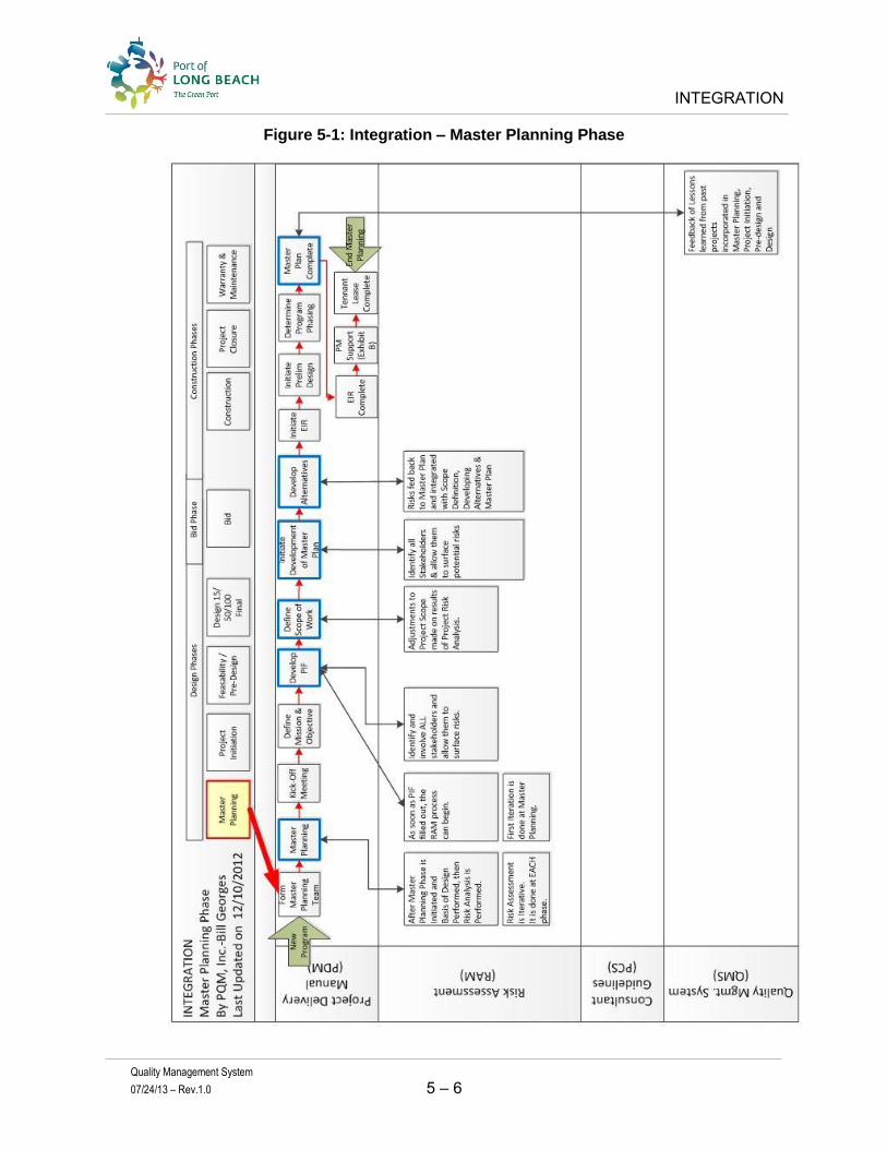
INTEGRATION
Quality Management System
07/24/13 – Rev.1.0 5 – 6
Figure 5-1: Integration – Master Planning Phase

INTEGRATION
Quality Management System
07/24/13 – Rev.1.0 5 – 7
Figure 5-2: Integration – Project Initiation Phase

INTEGRATION
Quality Management System
07/24/13 – Rev.1.0 5 – 8
Figure 5-3: Integration – Feasibility/Pre-Design Phase

INTEGRATION
Quality Management System
07/24/13 – Rev.1.0 5 – 9
Figure 5-4: Integration – Design Phase, 15% Milestone
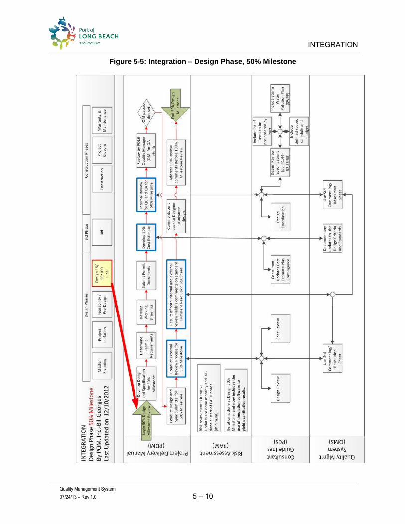
INTEGRATION
Quality Management System
07/24/13 – Rev.1.0 5 – 10
Figure 5-5: Integration – Design Phase, 50% Milestone

INTEGRATION
Quality Management System
07/24/13 – Rev.1.0 5 – 11
Figure 5-6: Integration – Design Phase, 100% Milestone
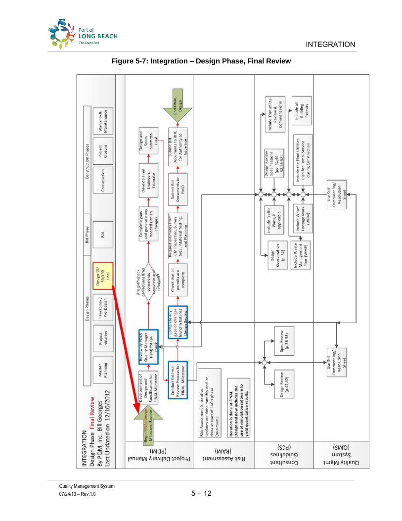
INTEGRATION
Quality Management System
07/24/13 – Rev.1.0 5 – 12
Figure 5-7: Integration – Design Phase, Final Review

INTEGRATION
Quality Management System
07/24/13 – Rev.1.0 5 – 13
Figure 5-8: Integration – Bid and Award Phase

INTEGRATION
Quality Management System
07/24/13 – Rev.1.0 5 – 14
Figure 5-9: Integration – Construction Phase

INTEGRATION
Quality Management System
07/24/13 – Rev.1.0 5 – 15
Figure 5-10: Integration – Project Closure Phase

Quality Management System 07/24/13 – Rev. 1.0
Appendix A
Contents:
POLB Monthly Status Report

Appendix A – POLB Monthly Status Report
POLB Monthly Status Report PM Division of the Engineering Bureau

Appendix A – POLB Monthly Status Report
POLB Monthly Project Status Report Month and Year
Project Start Date
Contract Type
Services
Dollar Value of Contract
Goals of Project
Other Key Information

Appendix A – POLB Monthly Status Report
Scope Schedule Budget
Red Yellow Green
Quality Risk Changes
Red Yellow Green
Note: status in yellow or red must be elaborated on next page
POLB Monthly Project Status Report Month and Year

Appendix A – POLB Monthly Status Report
Tracking No.
Urgency (H M L) Issue Resp. Due
Date Required
Participants Status
Note: If this is lengthy, it can be submitted as a separate attachment to the monthly status report.
POLB Monthly Project Status ReportMonth and Year

Quality Management System 07/24/13 – Rev. 1.0
Appendix B
Contents:
Itemized Submittal List
Designer’s QC Activity Schedule
Design Control Log
Sample QA Certification
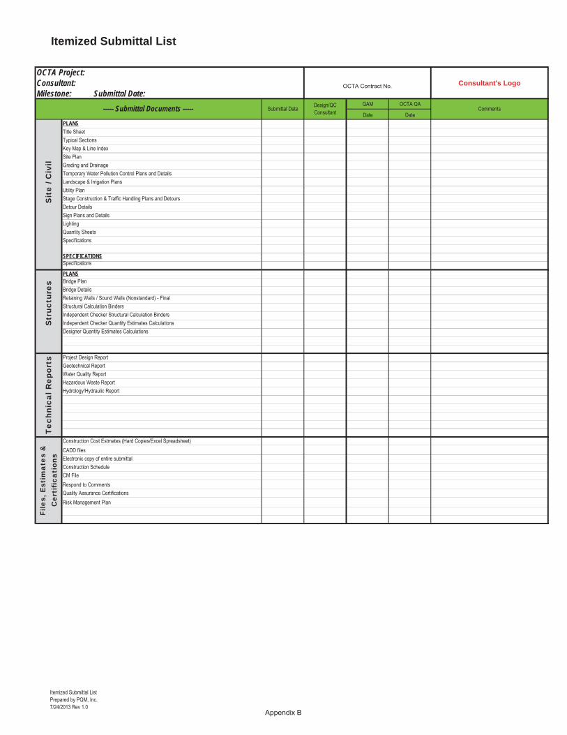
Itemized Submittal List
Itemized Submittal ListPrepared by PQM, Inc.7/24/2013 Rev 1.0
Appendix B
Consultant's Logo
QAM OCTA QA
Date DatePLANSTitle SheetTypical SectionsKey Map & Line Index Site PlanGrading and DrainageTemporary Water Pollution Control Plans and DetailsLandscape & Irrigation PlansUtility PlanStage Construction & Traffic Handling Plans and DetoursDetour DetailsSign Plans and DetailsLightingQuantity SheetsSpecifications
SPECIFICATIONSSpecifications
PLANSBridge PlanBridge DetailsRetaining Walls / Sound Walls (Nonstandard) - FinalStructural Calculation BindersIndependent Checker Structural Calculation BindersIndependent Checker Quantity Estimates CalculationsDesigner Quantity Estimates Calculations
Project Design ReportGeotechnical ReportWater Quality ReportHazardous Waste ReportHydrology/Hydraulic Report
Construction Cost Estmates (Hard Copies/Excel Spreadsheet)CADD filesElectronic copy of entire submittalConstruction ScheduleCM FileRespond to CommentsQuality Assurance CertificationsRisk Management Plan
Sit
e / C
ivil
Str
uctu
res
Tec
hnic
al R
epor
tsFi
les,
Est
imat
es &
C
erti
fica
tion
s
Comments
OCTA Project: Consultant: Milestone: Submittal Date:
OCTA Contract No.
----- Submittal Documents ----- Submittal Date Design/QC Consultant

Quality Control Activity Schedule
QC Activity SchedulePrepared by PQM, Inc. 7/24/2013 Rev 1.0 Appendix B
Project:
Consultant:
Submittal:
Start Finish Start Finish
1 Accuracy Checks
2 Discipline Review
3 Inter-Discipline Review
4 Management Review
5 QA Certification
6 Publish Documents
7 Submittal
QC ActivityPlanned Actual

Design Control Log
Design Control LogPrepared by PQM, Inc.7/24/2013 Rev 1.0 Appendix B
Name Date Name Date Name Date Name Date by date Name Date
1
2
3
4
5
6
7
8
9
10
Designer POLB
RECOMMENDATION SECTION ASSESSMENT SECTION RESOLUTION SECTIONDesign Document Implementation
Verified byItem # Ref.
Docs CommentProposed by
Response DrawingsApprove to Proceed by
Impacts to
APPROVAL TO IMPLEMENT
Design Revision Implemented and Update
Cost Schedule

Project Name
Submittal Certification
Prepared by PQM, Inc.7/24/2013 Rev 1.0
Consultant’s Logo
Submittal Description: _ ____________________________________ Date: ______________
Design Management
This submittal has been reviewed by me and found to meet the design criteria and contract requirements
Design Manager: _____________________________________ Date: ______________Name, Title.
Quality Management
The quality records for this submittal package were reviewed and found to be in compliance with the Design Quality Management Plan.
Quality Assurance Manager: __________________________________ Date: ______________
Name, Title.
Project Management
I find this submittal to meet the contract requirements and agree to release them to POLB.
Project Manager: _____________________________________ Date: ______________Name, Title
Document Control
The submittal documents have been uploaded to Project Quest
Document Control Manager: ____________________________ Date: ______________Name, Title

Quality Management System 07/24/13 – Rev. 1.0
Appendix C
Contents:
Sample Design Quality Management Plan (DQMP)

Design Quality Management Plan
Quality Management System
07/24/13-Rev.1.0 Appendix C i
Design Quality Management Plan
The Design Quality Management Plan is adopted for the above referenced project and will be implemented by (insert Designer’s name)
Recommended by: _______________________________________________ ________________ Quality Manager Date Approved by: _______________________________________________ ________________ Project Manager Date
Issue and Revision Record
Revision Date Description by Rev 0 4/20/2012 DQMP
All information provided by PQM, Inc. in this draft Design Quality Management Plan is for information purposes only and does not constitute a legal contract or agreement of any kind between PQM, Inc. and any person or entity unless otherwise expressly specified. Although the information found in this Design Quality Management Plan is believed to be reliable, no warranty, expressed or implied, is made regarding the accuracy, adequacy, completeness, legality, reliability, or usefulness of any information, either isolated or in the aggregate. Any opinion, advice, statement, service, offer, information, or content expressed or made available by a third party is that of third party and does not necessarily reflect that of PQM, Inc. All material is copyrighted by PQM, Inc. 2012

Design Quality Management Plan
Quality Management System
07/24/13-Rev.1.0 Appendix C ii
CONTENTS 1 QUALITY MANAGEMENT SYSTEM ................................................................................................ 1
1.1 Best Practices ............................................................................................................................... 1
1.2 Quality Goals and Objectives ...................................................................................................... 1
1.3 Design Objective ......................................................................................................................... 2
1.4 Design Submittal Process ............................................................................................................ 2
1.4.1 Design Development Phase ............................................................................................ 2
1.4.2 Design Review and Approval Phase .............................................................................. 2
1.5 Electronic Document Management System................................................................................. 2
1.6 Reference Documents .................................................................................................................. 2
1.7 Quality Management ................................................................................................................... 3
1.8 Change Management ................................................................................................................... 3
2 WORK PLAN ........................................................................................................................................ 5
3 ROLES AND RESPONSIBILIITES ...................................................................................................... 6
3.1 Project Management Organization .............................................................................................. 6
3.2 Project Quality Responsibilities .................................................................................................. 6
3.3 Project Manager/Design Manager Responsibilities ..................................................................... 6
3.4 Quality Manager Responsibilities ............................................................................................... 7
3.5 Discipline Leaders Responsibilities ............................................................................................. 7
3.6 Design (Technical) Staff Responsibilities ................................................................................... 8
3.7 Document Control Administrator Responsibilities ..................................................................... 8
3.8 Interface Management ................................................................................................................. 8
3.9 Communication Protocol ............................................................................................................. 8
4 DESIGN AND APPROVAL PROCESS ............................................................................................... 9
4.1 Design Development Process ...................................................................................................... 9
4.1.1 Design Initiation ............................................................................................................. 9
4.1.2 Design and Accuracy Checks ......................................................................................... 9
4.1.3 Design Review Program ............................................................................................... 10
4.2 Design Version Process ............................................................................................................. 13
4.3 Design Review and Agency Approval Process ......................................................................... 15
4.3.1 Agency Comments Resolution Process ........................................................................ 15
4.3.2 External Review ........................................................................................................... 15
4.3.4 Designer Responses ...................................................................................................... 17
5 QUALITY CONTROL PROCESS ...................................................................................................... 19
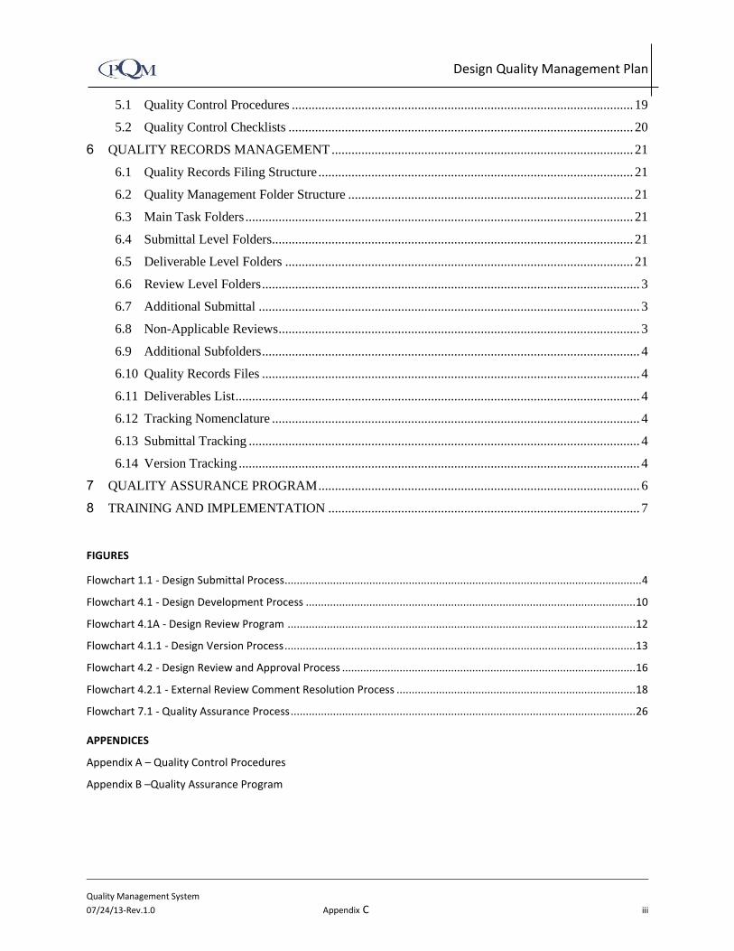
Design Quality Management Plan
Quality Management System
07/24/13-Rev.1.0 Appendix C iii
5.1 Quality Control Procedures ....................................................................................................... 19
5.2 Quality Control Checklists ........................................................................................................ 20
6 QUALITY RECORDS MANAGEMENT ........................................................................................... 21
6.1 Quality Records Filing Structure ............................................................................................... 21
6.2 Quality Management Folder Structure ...................................................................................... 21
6.3 Main Task Folders ..................................................................................................................... 21
6.4 Submittal Level Folders............................................................................................................. 21
6.5 Deliverable Level Folders ......................................................................................................... 21
6.6 Review Level Folders .................................................................................................................. 3
6.7 Additional Submittal ................................................................................................................... 3
6.8 Non-Applicable Reviews ............................................................................................................. 3
6.9 Additional Subfolders .................................................................................................................. 4
6.10 Quality Records Files .................................................................................................................. 4
6.11 Deliverables List .......................................................................................................................... 4
6.12 Tracking Nomenclature ............................................................................................................... 4
6.13 Submittal Tracking ...................................................................................................................... 4
6.14 Version Tracking ......................................................................................................................... 4
7 QUALITY ASSURANCE PROGRAM ................................................................................................. 6
8 TRAINING AND IMPLEMENTATION .............................................................................................. 7
FIGURES
Flowchart 1.1 - Design Submittal Process...................................................................................................................... 4
Flowchart 4.1 - Design Development Process ............................................................................................................. 10
Flowchart 4.1A - Design Review Program ................................................................................................................... 12
Flowchart 4.1.1 - Design Version Process .................................................................................................................... 13
Flowchart 4.2 - Design Review and Approval Process ................................................................................................. 16
Flowchart 4.2.1 - External Review Comment Resolution Process ............................................................................... 18
Flowchart 7.1 - Quality Assurance Process .................................................................................................................. 26
APPENDICES
Appendix A – Quality Control ProceduresError! Bookmark not defined.
Appendix B –Quality Assurance ProgramError! Bookmark not defined.

Design Quality Management Plan
Quality Management System
07/24/13-Rev.1.0 Appendix C iv
ABBREVIATIONS AND ACRONYMS
Caltrans California Department of Transportation
CAR Corrective Action Request
CEQA California Environmental Quality Act
CR Constructability Review
DQMP Design Quality Management Plan
DR Discipline Review
EDMS Electronic Data Management System
EIR Environmental Impact Report
EIS Environmental Impact Statement
IDR Inter-Discipline Review
ISO International Organization of Standardization
NEPA National Environmental Policy Act
QA Quality Assurance
QC Quality Control
SOW Scope of Work
SR State Route
WBS Work Breakdown Structure
VE Value Engineering

Design Quality Management Plan
Quality Management System
07/24/13-Rev.1.0 Appendix C v
DEFINITIONS
The following definitions are provided to ensure a uniform understanding of terms as they apply to this Design
Quality Management Plan.
Audit: A documented activity performed in accordance with written procedures or checklists to verify, by
examination and evaluation of objective evidence, that applicable elements being examined have been developed,
documented, and effectively implemented in accordance with specified requirements.
Change Control: An element of overall Configuration Management. This is a systematic evaluation, coordination
and approval or disapproval of any change to what was initially or previously approved. It also includes the
performances of those actions necessary to ensure that the final, delivered configuration of a system completely
matches its technical description in the approved engineering drawings, specifications, and related documents.
Checking: The word checking is used in this document to refer to the detailed accuracy checks performed by a
Checker during the check of calculations or drawings.
Configuration Control: Configuration control is defined as managing, documenting, and securing proper approvals
for any changes to the initial configuration and pertinent features of the Project.
Configuration Management: A management method of producing an end result which comprises three elements:
product identification, change control and configuration control. Configuration management may be distributed
throughout a number of organizational entities.
Constructability Review: A review of plans and specifications for buildability and bidability.
Controlled Document: This is a document which contains information intended for restricted distribution &
revision control. The document must be periodically reviewed and updated, as required.
Corrective Action: Documented commitment of specific action being planned or implemented to resolve a known
and identified condition or conditions adverse to Quality.
Corrective Action Request (CAR): A document issued to the consultant whose activities are not meeting
requirements. A CAR is a time sensitive document since there is a sense of urgency to close the CAR to properly
remedy the root cause.
Deficiency: A deviation from the design or specification requirements.
Design Verification: The process of reviewing, confirming or substantiating the design by one or more methods to
provide assurance that the design meets the specified design input. Acceptable methods of design verification are
design reviews, alternate calculations, qualification testing or combinations thereof.
Design: A technical and management process which creates, fashions, executes, or documents according to a pre-
determined plan or requirement. This refers to preparation of environmental studies, EIR/EIS or engineering
documents.
Design Criteria: standards that will be used to prepare the design.
Design Review: The review of design for the purpose of detection and remedy of design deficiencies which would
affect fitness-for-use and environmental aspects of the product, process or service, and/or identification of
potential improvements of performance, safety and economic aspects.

Design Quality Management Plan
Quality Management System
07/24/13-Rev.1.0 Appendix C vi
Deviation: A specific written authorization to depart from a particular code standard, design, specification,
drawing, or other requirement. A deviation differs from a design change in that an approved design change
requires formal approval and revision of the documentation defining the affected item, whereas a deviation does
not contemplate revision of the applicable specification or drawing.
Discipline Review: Checking design documents within the originating discipline.
Disposition: A statement describing the manner in which a deficiency or nonconformance is to be resolved.
Document: An original or official paper serving as the basis, proof, or support of something. Also, writing
conveying information. Documents may include, but are not limited to, loose-leaf or bound books, drawings
(tracings and/or reproductions), engineering calculations, procedures, specifications, standards, reports, manuals,
and other material generated which affects quality.
Document Control: The document control is the function of managing the document flow and storage in an
organization through various functions and processes. These include maintaining files and using proper distribution
and revision procedures.
Documentation: Any written or pictorial information describing, defining, specifying, reporting, or certifying
activities, requirements, procedures, or results.
Guidelines: Particular provisions which are considered good practice but which are not mandatory in programs
intended to comply with this standard. The term “should” denotes a guideline; the term “shall” denotes a
mandatory requirement.
Inter-Discipline Review: The review of design documents by engineering disciplines other than the originating
discipline.
Nonconformance: A discrepancy in characteristic, documentation, or procedure which affects form, fit or function
and renders the quality of an item or service unacceptable or indeterminate in regard to meeting all relevant
project requirements.
Objective Evidence: Any statement of fact, information, or record, either quantitative or qualitative, pertaining to
the Quality of an item or service based on observations, measurements or tests which can be verified.
Preliminary Design Review: A design review which takes place after conceptual design and prior to release for
Preliminary Design.
Procedure: A document that specifies or describes how an activity is to be performed. It may include methods to
be employed, equipment or materials to be used, and sequence of operation.
Quality Assurance (QA): All those planned and systematic actions necessary to provide adequate confidence that
an item is in conformance with established requirements, and will satisfy given needs. The activity of providing the
evidence needed to establish confidence that quality functions are being performed adequately. QA is a system
management tool.
Quality Audit: A systematic and independent examination to determine whether quality activities and related
results comply with planned arrangements and whether these arrangements are implemented and are suitable to
achieve objective.

Design Quality Management Plan
Quality Management System
07/24/13-Rev.1.0 Appendix C vii
Quality Control (QC): Those functions which provide a means to control and measure characteristics as related to
established system requirements. These are techniques and activities that sustain an item to satisfy a given need.
QC is also the use of such techniques and activities. QC is a production tool.
Quality Management: That aspect of the overall management function that manages, determines, and
implements the Quality Policy.
Quality Policy: The overall quality mission and direction of an organization as it regards quality.
Quality Procedure: A procedure describing the method(s) used to meet quality requirements and determine how
functional organizations collaborate to accomplish these requirements.
Quality Program: The coordinated execution of applicable QA and QC plans and activities for a project.
Quality System: The organizational structure, responsibilities, procedures, processes and resources for
implementing Quality Management.
Surveillance: Monitoring, witnessing or observing to verify whether or not an item or activity conforms to specific
requirements.

Design Quality Management Plan
Quality Management System
07/24/13-Rev.1.0 Appendix C 1
1 QUALITY MANAGEMENT SYSTEM
The Design Quality Management Plan (DQMP) outlines the overall framework and implementation of the
quality program for (insert Project name). The DQMP comprises a written quality policy, procedures, and
management’s commitment, which supports the quality program and assigns personnel to complete
quality activities. The purpose of this plan is to provide direction for the maintenance of a robust quality
program for the project delivery process. This includes initiating the project activities; design
development; quality control checks and reviews; a quality assurance program; a design approval process,
and the day–to-day interaction with various stakeholders.
The DQMP has eight sections:
1. Quality Management System
2. Work Plan
3. Roles and Responsibilities
4. Design and Approval Process
5. Quality Control Process
6. Quality Records Management
7. Quality Assurance Program
8. Training and Implementation Plan
The DQMP outlined here may be adopted without modification. The requirements of the DQMP are
accountable by (insert Designer name). The Quality Manager will review the actual Quality Management
System for compliance with the DQMP. The elements which make up the DQMP will be revised to
improve the program and the project delivery performance.
1.1 Best Practices
(Insert Designer’s name) is committed to perform professional engineering services using its quality
management best practices on each contract assignment and task. Many of their quality best practices
are presented here in this DQMP, as specific processes and procedures.
1.2 Quality Goals and Objectives
(Insert Designer’s name) is committed to completing the design development that will meet the
expectations of (insert client’s name). The Design Consultant Team will complete all work products
needed to fulfill the contract requirements by using and following the generally accepted standards of
practice for civil engineering.
(Insert Designer’s name) intends to meet these objectives by maintaining consistent lines of
communication among all members of the Design Team, (insert Agency’s name), and other stakeholders.

Design Quality Management Plan
Quality Management System
07/24/13-Rev.1.0 Appendix C 2
1.3 Design Objective
The design objective is to further develop the contract deliverables based on the scope of services, design
criteria and standards.
1.4 Design Submittal Process
The Design Consultant has implemented these processes for the development and control of technical
and design activities. The project delivery process is accomplished in two distinct phases, as shown in
Flowchart 1.1 – Design Delivery Process.
Comments from the reviewing agencies regarding the submittal packages will be resolved between the
client, reviewing and approving agency and the Design Consultant. This design submittal process is
repeated for each submittal package, until approval occurs. After all of the comments have been resolved
with the agencies, then the approving agency will issue approval. The design will then advance to the next
phase of the project, which is beyond the scope of this document.
1.4.1 Design Development Phase
The Design Development Process includes project initiation, design preparation and a rigorous internal
checking and reviewing process covered in eleven quality control procedures. Section 4 discusses this
process in detail and is illustrated in Flowchart 4.1, Design Development Process.
1.4.2 Design Review and Approval Phase
Once the Design Development Phase is complete, then the milestone submittal package is assembled and
submitted to the reviewing and approving agencies for review. The reviewers will provide review
comments that are evaluated by the Design Consultant followed by resolution of the comments. Section 4
discusses this in detail and is illustrated in Flowchart 4.2., Design Review and Approval Process.
1.5 Electronic Document Management System
The Design Consultant uses an electronic data management system (EDMS), for managing and sharing the
design documents, and the quality control and assurance documents.
These folders are accessible via an internet connection from anywhere and at anytime by the production
staff, project management and quality management. These folders will have the most current scope of
work, schedule, and quality records that contain copies of document versions after quality reviews and
agency reviews have been conducted. As a result, management will be able to continuously monitor and
audit the progress of all activities for the delivery and preparation timely reports.
The filing system presented in Section 6-Quality Records Management, is designed to be transparent to all
staff working for the project. The folders reserved for these documents do not encroach or hinder any of
the administrative, financial, or design development folders. They only house quality records.
1.6 Reference Documents
The documents noted in this section shall be used by Design Consultant to implement the Quality
Management Program as applicable to their work and to establish design uniformity.

Design Quality Management Plan
Quality Management System
07/24/13-Rev.1.0 Appendix C 3
Contract scope of services
Subconsultant requirements
Applicable municipal, federal, and state codes, design guidance, criteria, and standards
List specific design basis document
1.7 Quality Management
A Quality Manager has been assigned for this phase of the project. The Quality Manager is responsible for
developing a Design Quality Management Plan that meets the contract requirements, the standards of
practice, provides an efficient program that fits the size and complexity of the project, and is sufficiently
effective to achieve the expected quality goals. The Quality Manager will implement the quality program,
train the staff, monitor the quality program, conduct periodic audits and surveillances and submit
monthly reports throughout each phase of work. The quality control and quality assurance activities are
discussed in more detail in Section 5 and Section 7, respectively.
1.8 Change Management
A Design Control Log will be implemented towards the end of the Design Phase to track any significant
changes to the design as it advances the final approval. This will be documented using the Design Control
Management Log sheet.

Design Quality Management Plan
Quality Management System
07/24/13-Rev.1.0 Appendix C 4
Flowchart 1.1: Design Delivery Process

Design Quality Management Plan
Quality Management System
07/24/13-Rev.1.0 Appendix C 5
2 WORK PLAN
Project Management has developed a comprehensive scope of work, list of deliverables and the master
schedule for the project.
The Scope of Work will provide an itemized list of deliverables, and will accompany each milestone
submittal. It will itemize the drawings, reports, studies, specifications, and cost estimate products that will
be included with the submittal. A micro schedule that details the quality control activities will be
prepared in advance of each milestone event. Generally, this will provide a detailed look at the checking
and review activities that take place in a reasonable and sufficient period prior to the submittal. The micro
schedule shall allow sufficient time to conduct the accuracy checks, Discipline Review, Inter-Discipline
Reviews, Management Review, CADD production, development of the files (pdf), checking of the CADD
drawings, compiling the drawing sets, reports, specifications, reproduction, and final packaging and
delivery.

Design Quality Management Plan
Quality Management System
07/24/13-Rev.1.0 Appendix C 6
3 ROLES AND RESPONSIBILIITES
3.1 Project Management Organization
The Design Consultant shall be organized in such a manner that:
Quality is achieved and maintained by those who have been assigned responsibility for performing
the work.
Persons or organizations not directly responsible for performing the work will verify quality
achievement.
The adequacy and effectiveness of the DQMP will be regularly and formally assessed by the Project
Manager.
Conformance to project requirements will be assessed through surveillance and audits directed by
the Quality Manager.
Proper level of authority and empowerment is provided for all DQMP stakeholders.
3.2 Project Quality Responsibilities
Managers and Discipline Leaders are responsible for implementing and maintaining the DQMP, for
adhering to the plan in their service areas and for answering staff’s questions about the DQMP. All
project personnel, including employees, managers and discipline leaders are responsible for complying
with the DQMP requirements. A copy of the DQMP is available at the project office, and at each office
where work is being performed. The DQMP and the quick reference guide are also posted on the EDMS.
3.3 Project Manager/Design Manager Responsibilities
Endorse and implement the approved DQMP.
Support the requirements of the DQMP with the appropriate schedule and budget.
Provide adequate resources for QC activities.
Incorporate adequate time in the schedule to comply with the DQMP process.
Coordinate and communicate with the Quality Manager to properly implement and maintain the
expected quality of the products produced by the Design Consultant.
Ensure that the Quality Control procedures are applied for each deliverable.
Perform sequential Discipline and Inter-Discipline reviews for each deliverable.
Ensure that the Discipline Leaders conduct the quality control activities within their respective
disciplines of work.
Empower the Quality Manager to implement and maintain a robust DQMP.
Select qualified staff and manage their activities.

Design Quality Management Plan
Quality Management System
07/24/13-Rev.1.0 Appendix C 7
3.4 Quality Manager Responsibilities
Report on all quality activities, issues, metrics, and leading indicators. This includes a written
quarterly report describing same.
Maintain routine communication with Management and Discipline Leaders on quality issues that
could affect the performance of the project team.
QA (Regularly assess and document the adequacy and effectiveness of the DQMP.)
Identify the key quality indicators, such as design deficiencies, effectiveness of interface
management, inadequate stakeholder participation, etc. These will be used as metrics to determine
the health of the quality program.
Keep the Project Manager and the Design Manager apprised of quality issues and strategies for
improvement.
Assure that the DQMP is established, accepted, implemented and maintained by all project team
members.
Provide consultation to the project team regarding the plan and implementation of quality.
Monitor and evaluate DQMP implementation for adequacy and effectiveness.
Resolve conflicts regarding the intent of the DQMP.
Verify effectiveness and compliance with the approved DQMP processes and procedures. This can be
done via surveillance, inspection, review of documentation, and audits (or other means), as required.
Direct and document the audit and surveillance activities.
Develop and implement a training plan for the quality program.
Review the design submittal packages prior to submittal, for compliance with the DQMP.
Prepare and submit written monthly reports describing the quality activities.
3.5 Discipline Leaders Responsibilities
The Discipline Leader is ultimately responsible for:
The work prepared within their discipline.
Following the design criteria, standards, and guidance required by the approving agencies.
Implementing the quality control procedures within their discipline of work.
Conducting accuracy checks of the work prepared.
Conducting Discipline Reviews of their packages.
Conducting timely individual Inter-Discipline Reviews prior to IDR Workshops.
Contributing to the IDR Workshop.
Ensuring that the technical staff is properly trained on the quality control procedures

Design Quality Management Plan
Quality Management System
07/24/13-Rev.1.0 Appendix C 8
Notifying the Quality Manager of any known or perceived deficiencies in the quality management
program.
3.6 Design (Technical) Staff Responsibilities
The technical production staff will:
Produce quality documents
Follow direction provided by the Discipline Leader or designee
Prepare the design consistent with the design criteria, standards and guidance.
Identify conflicts or potential conflicts among disciplines of work.
Check their own work to the best of their ability prior to starting the accuracy checking procedures.
Follow the quality control procedures and quality control mechanics (color code system, use of
stamps, the checking process, etc.).
3.7 Document Control Administrator Responsibilities
Place the electronic records in the proper location within the electronic data management system
(EDMS).
Assist in searching the database for documents, as needed.
Transmit the documents for submittal.
3.8 Interface Management
The objective of the interface management process is to facilitate agreements with other stakeholders
regarding roles and responsibilities, to provide timing of interface information, and to identify the critical
interface issues early in the project. The overall goals of this process are the early identification of issues
with potential impact on cost or schedule, and then the minimization or removal of their negative impact
by promoting clear, accurate, timely, and consistent communication with these other stakeholders.
The interface management process will facilitate the exchange of project information in order to keep the
stakeholders working together to deliver the scheduled project tasks. This project information can
include engineering analysis, calculations, drawings, reports, specifications, and project schedule.
3.9 Communication Protocol
All project correspondence outside the Design Consultant will require the Project Manager’s approval. In
addition, the Project Manager shall be included in all meeting note distribution lists. Any change in the
scope of work will be directly communicated by the Project Manager. The Discipline Leaders will make the
decisions regarding technical requirements for specific disciplines of design.

Design Quality Management Plan
Quality Management System
07/24/13-Rev.1.0 Appendix C 9
4 DESIGN AND APPROVAL PROCESS
This section presents two sub-processes to the Design Delivery Process described in Section 1 and shown
in Flowchart 1.1. These processes provide the Internal Design Development Process and the External
Design Review and Approval Process. There are additional processes that describe how the Design
Versioning Process and the External Review Comment Resolution Process works. Flowcharts for each of
these are presented within this section.
4.1 Design Development Process
The Design Development Process is a high level process describing the internal activities performed by the
Design Consultant, leading up to a submittal for external review. It has three distinct phases, as shown in
Flowchart 4.1: Design Development Process.
As shown on the flowchart, the left side shows different positions or roles. Each position is associated
with a swim lane that covers the entire length of the chart. The passage of time is represented on the
horizontal axis, from left to right. The work activities or tasks that are the responsibility of each position
will be located in the corresponding swim lane.
This chart shows the specific design responsibilities that are a part of this process. The Project
Management, Document Control and Quality Assurance activities continue throughout each phase, all the
way through to the submittal.
4.1.1 Design Initiation
The Design Manager will initiate the early project activities that are critical to completing the design of the
Project. These activities may include surveying, geotechnical field investigations, utility pot holing, and
laboratory analysis. Also, if additional equipment that is necessary will require setup, then new software
and hardware purchases will need to be configured, and the non-commercial software will need to be
validated. The Quality Control Procedures (QC-2 thru QC-6), in Appendix A, provide guidance for these
initial activities.
4.1.2 Design and Accuracy Checks
Under the direction of the Design Manager, the Discipline Leaders (DLs) will develop the design using
established design criteria and standards that are acceptable to the reviewing and approving agencies.
For each milestone submittal, design packages are coordinated and prepared for internal review under
the direction of each Discipline Leader. During the development of each discipline package, the Discipline
Leader is responsible for ensuring that the accuracy checks for all of the technical documents are
completed for the specific submittal package. The QC Checklist requires that an accuracy checks be
conducted for specific tasks, including the checking of:
calculations;
the results of calculations provide dimensions, sizes, etc. that are shown on drawings;
field investigation data, laboratory results, analysis of the data generally lead to the conclusions
and recommendations provided in body of a report and provided in the appendix; and

Design Quality Management Plan
Quality Management System
07/24/13-Rev.1.0 Appendix C 10
dimensions, units of measure called out in specifications.
Flowchart 4.1: Design Development Process

Design Quality Management Plan
Quality Management System
07/24/13-Rev.1.0 Appendix C 11
4.1.3 Design Review Program
There are multiple submittals that will take place during this phase. Discipline Reviews are required in
order to ensure that the discipline package meets the design criteria and standards established for the
project. After each discipline has completed their discipline packages, they are combined into a submittal
package and distributed to the Reviewers for an Inter-Discipline Review. After this review is complete, a
Management Review takes place. This is detailed in Flowchart 4.1A: Design Review Program.
The Discipline Review may be completed concurrently with the accuracy check, as determined by the
Discipline Leader. However, the Discipline Reviews will be conducted prior to the Inter-Discipline,
Constructability, and Management Reviews.
The Discipline Reviews are followed by the Inter-Discipline Review (IDR), and a concurrent or sequential
Constructability Review, as required. The objective of the IDR is to identify conflicts or potential conflicts
that will interfere with the construction of each project element. In addition, ensure that the design
criteria and standards are applied consistently throughout the project or as required by the approving
agency. Each Discipline Leader will individually conduct an IDR (individual IDR) for each disciplines of work
that may potentially conflict or interfere with their discipline of work. It is encouraged, but optional, to
follow the individual IDR with an IDR Workshop. This is at the discretion of the Design Manager.
At the completion of each design review, the comments are resolved and the technical documents are
updated, checked for accuracy and verified.
A complete submittal package is prepared and provided for the Management Review. The Management
Review consists of a final review and recommendation of the entire submittal package, the Quality
Assurance Manager’s certification of compliance with the DQMP, and the Project Manager’s approval and
transmittal of the submittal package for external review to the Reviewing and Approving agencies.

Design Quality Management Plan
Quality Management System
07/24/13-Rev.1.0 Appendix C 12

Design Quality Management Plan
Quality Management System
07/24/13-Rev.1.0 Appendix C 13
4.2 Design Version Process
The Document Version Process is shown in Flowchart 4.1.1, Design Version Process, which describes the
process of attaching a version number to the name of the document at the completion of every quality
control check and review.
Although, there are only two to four major milestone submittals, there will be multiple technical studies
for submittals over the course of the project, and these deliverables are expected to achieve approval
with no more than two submittals. To keep the tracking of documents straightforward and unambiguous,
a standard file naming system has been developed that all personnel working on this project will follow.
All documents that are part of a submittal package should be identified by using the naming conventions
shown in the document control plan.
The specific version number is determined by the last internal review (listed below) that has been
completed on that document. As shown in Figure 4-2, before each agency submittal, there will be four
different types of internal reviews for each document described in the previous section:
A completed Accuracy Check will result with document name being tagged by version 0 (V0)
A completed Discipline Review will result with document name being tagged by version 1 (V1)
A completed Inter-Discipline Review will result with document name being tagged by version 2 (V2)
A completed Management Review will result with document name being tagged by version 3 (V3)
Revisions will be made to the document package based on comments and corrections recommended
from each review. When the revisions from a review are incorporated into the document, and then
checked and verified, the Version number of the document package will change to match the version
number listed above. For example, only after the revisions have been incorporated, checked and verified,
from the Inter-Discipline Review, will the name of the document package is changed to include version 2.
The letter S, followed by a number will be used to identify the Submittal number. The letter V, followed
by a number will be used to track the version number. For Example, the following nomenclature will
signify different versions of the document package leading up to the first Agency Submittal: S1V0, S1V1,
S1V2, and S1V3. Then, after it has been submitted, and the comments have been received, the next set of
numbers for the second submittal will be S2V0, S2V1, S2V2, S2V3, etc. Also, the applicable Quality Control
Procedures will be used to complete the final deliverables.

Design Quality Management Plan
Quality Management System
07/24/13-Rev.1.0 Appendix C 14
Flowchart 4.1.1: Design Version Process

Design Quality Management Plan
Quality Management System
07/24/13-Rev.1.0 Appendix C 15
4.3 Design Review and Agency Approval Process
The Agency Approval Process, shown in Flowchart 4.2: Design Review and Approval Process, defines the
sequence for the design submittals as:
1. Design Initiation, which is the design basis to start the next Phase of Work.
2. Initial Submittal.
3. Draft ED and Project Report.
4. Final ED and Project Report.
5. Design Approval is the approved final PA/ED documents that will be used to support the Design-Build
procurement phase.
During the development and advancement of the design, there are internal and external reviews that are
completed. Each milestone requires that the design documents go through the accuracy checks and the
design reviews, as previously discussed in this section.
The PSR/PR and Environmental Document will be followed by the development of the final design. The
final design will have up to five (5) milestones. The Final Design Phase will follow the same sequencing
discussed above.
4.3.1 Agency Comments Resolution Process
The Agency Comments Resolution Process, presented in Flowchart 4.2.1: External Review Comment
Resolution Process shows the process in two phases: 1) the External Review Phase, and 2) the Designer
Response Phase. This work is accomplished by the coordination of people in 3 separate positions or roles.
They are: the Reviewing Agency, the Design Manager and the Discipline Leaders.
4.3.2 External Review
The Project Manager will submit design packages to the Agency, unless other direction has been
authorized by Agency’s Project Manager. If this is the case, the Project Manager could forward the design
packages directly to the appropriate agency to perform reviews and provide comments.
Usually, the first step in this process is for members of the Agency’s review team to conduct their design
review and to prepare their formal comments in the appropriate Review Comments and Response Log
Sheet. Once the other agency reviews are complete, and comments are formally documented, the next
step is for the package (and the comments) to be sent back to Agency, and the Design Consultant.

Design Quality Management Plan
Quality Management System
07/24/13-Rev.1.0 Appendix C 16
Flowchart 4.2: Design Review and Approval Process
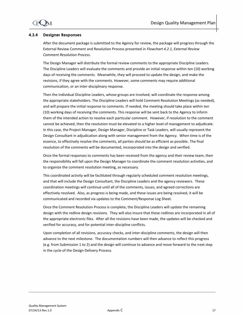
Design Quality Management Plan
Quality Management System
07/24/13-Rev.1.0 Appendix C 17
4.3.4 Designer Responses
After the document package is submitted to the Agency for review, the package will progress through the
External Review Comment and Resolution Process presented in Flowchart 4.2.1, External Review
Comment Resolution Process.
The Design Manager will distribute the formal review comments to the appropriate Discipline Leaders.
The Discipline Leaders will evaluate the comments and provide an initial response within ten (10) working
days of receiving the comments. Meanwhile, they will proceed to update the design, and make the
revisions, if they agree with the comments. However, some comments may require additional
communication, or an inter-disciplinary response.
Then the individual Discipline Leaders, whose groups are involved, will coordinate the response among
the appropriate stakeholders. The Discipline Leaders will hold Comment Resolution Meetings (as needed),
and will prepare the initial response to comments. If needed, the meeting should take place within ten
(10) working days of receiving the comments. This response will be sent back to the Agency to inform
them of the intended action to resolve each particular comment. However, if resolution to the comment
cannot be achieved, then the resolution must be elevated to a higher level of management to adjudicate.
In this case, the Project Manager, Design Manager, Discipline or Task Leaders, will usually represent the
Design Consultant in adjudication along with senior management from the Agency. When time is of the
essence, to effectively resolve the comments, all parties should be as efficient as possible. The final
resolution of the comments will be documented, incorporated into the design and verified.
Once the formal responses to comments has been received from the agency and their review team, then
the responsibility will fall upon the Design Manager to coordinate the comment resolution activities, and
to organize the comment resolution meeting, as necessary.
This coordinated activity will be facilitated through regularly scheduled comment resolution meetings,
and that will include the Design Consultant, the Discipline Leaders and the agency reviewers. These
coordination meetings will continue until all of the comments, issues, and agreed corrections are
effectively resolved. Also, as progress is being made, and these issues are being resolved, it will be
communicated and recorded via updates to the Comment/Response Log Sheet.
Once the Comment Resolution Process is complete, the Discipline Leaders will update the remaining
design with the redline design revisions. They will also insure that these redlines are incorporated in all of
the appropriate electronic files. After all the revisions have been made, the updates will be checked and
verified for accuracy, and for potential inter-discipline conflicts.
Upon completion of all revisions, accuracy checks, and inter-discipline comments, the design will then
advance to the next milestone. The documentation numbers will then advance to reflect this progress
(e.g. from Submission 1 to 2) and the design will continue to advance and move forward to the next step
in the cycle of the Design Delivery Process.

Design Quality Management Plan
Quality Management System
07/24/13-Rev.1.0 Appendix C 18
Flowchart 4.2.1: External Review Comment Resolution Process

Design Quality Management Plan
Quality Management System
07/24/13-Rev.1.0 Appendix C 19
5 QUALITY CONTROL PROCESS
The Quality Control Process will be a thorough implementation of the applicable Accuracy Checking and
the Design Reviews following the eleven (11) Quality Control Procedures in Appendix A.
The QC Procedures can be categorized in four Groups:
1. Quality Control Mechanics (QC-1) defines the fundamental requirements such as the color code
system, use of stamps, conflict resolution and minimum staff qualifications.
2. Project Initiation (QC-2 thru QC-5) such as setting up hardware and software, configuring software,
software validation and maintaining field equipment.
3. Design Development Process requires that the design be developed in accordance with the contract
requirements, CADD requirements (applicable CADD manual), design criteria, design Standards and
applicable design directive.
4. Design Accuracy Checks (QC-6 thru QC-10) are surveying and mapping, calculations, drawings,
reports, and specifications during the design development phase. Best practice is for the accuracy
checks to take place as the design progresses for each drawing or other work product. Alternatively,
the design may be advanced to a complete state, as directed by the design Originator, then
conducted by accuracy checks for the entire discipline of work. It is acceptable that the Discipline
Review be conducted concurrently with the accuracy checks. This is at the discretion of the Discipline
Leader and in concurrence with the Quality Manager.
5. Design Review Program (QC-11) defines the Discipline Review (DR), Inter-Discipline Review (IDR),
Constructability Review (CR), and Management Review (MR).
Proper implementation of the Design Review Program will ensure consistency between the design
documents and the constructability of the design. The Design Review Program is structured to examine all
documents for consistency, completeness and conflicts between different disciplines or work. Each review
in the process will take place sequentially. Any variation from the predefined process will require the
approval of the Quality Manager.
5.1 Quality Control Procedures
The following quality control procedures are located in Appendix A: QC-1: Design Checking Protocol QC-2: Office Electronic System Setup QC-3: Software Validation QC-4: CADD Requirement QC-5: Field Equipment QC-6: Checking Surveying and Mapping QC-7: Checking Calculations QC-8: Preparation and Checking Drawings QC-9: Preparation and Checking Reports QC-10: Checking Specifications QC-11: Design Review Program

Design Quality Management Plan
Quality Management System
07/24/13-Rev.1.0 Appendix C 20
5.2 Quality Control Checklists
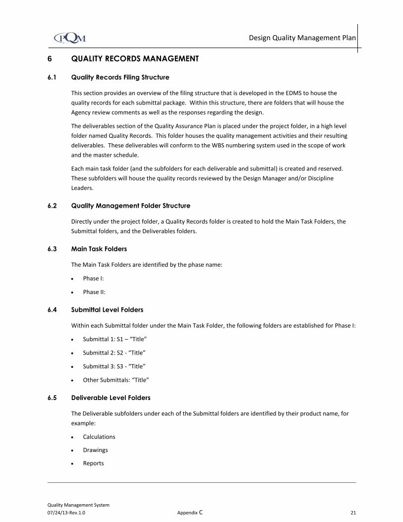
Design Quality Management Plan
Quality Management System
07/24/13-Rev.1.0 Appendix C 21
6 QUALITY RECORDS MANAGEMENT
6.1 Quality Records Filing Structure
This section provides an overview of the filing structure that is developed in the EDMS to house the
quality records for each submittal package. Within this structure, there are folders that will house the
Agency review comments as well as the responses regarding the design.
The deliverables section of the Quality Assurance Plan is placed under the project folder, in a high level
folder named Quality Records. This folder houses the quality management activities and their resulting
deliverables. These deliverables will conform to the WBS numbering system used in the scope of work
and the master schedule.
Each main task folder (and the subfolders for each deliverable and submittal) is created and reserved.
These subfolders will house the quality records reviewed by the Design Manager and/or Discipline
Leaders.
6.2 Quality Management Folder Structure
Directly under the project folder, a Quality Records folder is created to hold the Main Task Folders, the
Submittal folders, and the Deliverables folders.
6.3 Main Task Folders
The Main Task Folders are identified by the phase name:
Phase I:
Phase II:
6.4 Submittal Level Folders
Within each Submittal folder under the Main Task Folder, the following folders are established for Phase I:
Submittal 1: S1 – “Title”
Submittal 2: S2 - “Title”
Submittal 3: S3 - “Title”
Other Submittals: “Title”
6.5 Deliverable Level Folders
The Deliverable subfolders under each of the Submittal folders are identified by their product name, for
example:
Calculations
Drawings
Reports

Design Quality Management Plan
2
Specifications
Cost Estimates

6.6 Review Level Folders
Within each Submittal, there will be five subfolders created and reserved. These folders will house the
resulting documents from each of the separate internal and agency quality reviews (such as the Accuracy
Check, the Discipline Review, the Inter-Discipline Review, etc.). Here are some examples:
S1V0 – Accuracy Check (AC) & Checked Document (Submittal 1 Version 0)
S1V1 - Discipline Review (DR) & Reviewed Document (Submittal 1 Version 1)
S1V2 – Inter-Discipline Review (IDR) & Coordinated Document (Submittal 1 Version 2)
S1V3 – Management Review (MR) & Submitted Document (Submittal 1 Version 3)
S1V4 – This folder will serve as a holding area for the Agency Review comments, Design
Consultant’s responses and their resolutions. Once this is complete, the document package will be
updated and advanced to the next submittal level (S2).
6.7 Additional Submittal
For the second Submittal, the following folders and subfolders will be populated with the relevant
documents S2-Submittal 2:
S2V0 – Accuracy Check & Advanced Document (Submittal 2 Version 0)
S2V1 – Discipline Review (DR) & Reviewed Document (Submittal 2 Version 1)
S2V2 – Inter-Discipline Review (IDR) & Coordinated Document (Submittal 2 Version 2)
S2V3 – Management Review (MR) & Submitted Document (Submittal 2 Version 3)
S2 V4 – This folder will serve as a holding area for the Agency Review (AR) material and will include
both the Agency comments, and their resolutions. Once this is done, the document package will
advance to the next submittal level (S3).
The third submission to the agency is called the S3 Folder and follows the same folder naming convention.
Associated subfolders will be S3V0, S3V1, S3V2, S3V3, and Final approved and dated.
6.8 Non-Applicable Reviews
If any of the reviews are not applicable, then the folder will be deleted or marked N/A. However, the
version numbers for the subsequent reviews will continue to remain the same and follow the existing
pattern and nomenclature.
For example, if S2V2 is not needed, then the folder will be deleted or marked N/A. However, the next
folder S2V3 will remain open, and will continue to be used to store the Management Review
documentation.

6.9 Additional Subfolders
In addition, under each deliverable folder, additional subfolders may be created to house the final
documents for the deliverable, and the other to house the QA monitoring and auditing activities for the
deliverable, as necessary.
6.10 Quality Records Files
In order to track the work progress of all the deliverables in a timely manner, the following prerequisite
activities need to be accomplished (see 6.3.1, 6.4, 6.4.1, and 6.4.2).
6.11 Deliverables List
A list of deliverables required for each submittal will be produced. This will include the drawings, reports,
specifications, cost estimate and other items required for the submittal to be complete. In this list, each
deliverable will include their Task Manager, and their Discipline Leader. This list may be produced in a
spreadsheet. In addition to the list of deliverables, there will be an itemized drawing list that specifies the
drawing titles as on the drawing index sheet.
Both document lists will be maintained by the Document Control Manager in coordination with Discipline
Leaders and the Design Manager.
6.12 Tracking Nomenclature
It is important to remember that a document or submittal package is defined as an individual deliverable,
or a group of documents combined into a package that needs to be submitted to the agency for review
and approval. Each document and/or package must have an assigned name, so that it can be tracked by
attaching a submittal number and a version number (SxVx) to the end of its file name.
6.13 Submittal Tracking
The progress of each submittal package will be recorded and tracked in the Quality Records. There will be
three possible submittal folders for Phase I. They are as follows:
Initial Submittal (S1) – Screencheck PA/ED
Intermediate Submittal (S2) – Draft PA/ED
Final Submittal (S3) – Final PA/ED
The number of these folders can be adjusted depending on the number of submittals needed for the
Document or Submittal Package to become Agency approved.
6.14 Version Tracking
Document versions will be assigned to each document after it has been revised to incorporate the
resolution of the comments. This versioning process will be done as follows:
Version 0: (V0) will be attached to the end of the document name after all the revisions have been
incorporated from the accuracy check in the design development Phase. This document can be called
the Initial Document or Checked Document.

Version 1: (V1) will be attached to the end of the document name after all the revisions have been
incorporated from the Discipline Review part of the Internal Review Phase. This document can be
called the ‘Reviewed Document’.
Version 2: (V2) will be attached to the end of the document name after all the revisions have been
incorporated from the Inter-Discipline Review. Any additional reviews, like a Constructability Review,
will be included in this review phase. This document can be called the ‘Coordinated Document’.
Version 3: (V3) will be attached to the end of the document name after all the revisions have been
incorporated from the Management Review. This version of the document (V3), after QA
Certification, will always be the version that will be submitted to the Agency for review and approval.
This document can be called the ‘Submitted Document’.
Version 4: (V4) will be attached to the end of the document name after the revisions have
incorporated all the resolutions from the Agency Review. This document can be called ‘the Advanced
Document’ because it will be “advanced” to the next step in the process.
The Advanced Document then will have three possible cases for its next step:
Case 1: it will advance to the next submittal process under the same WBS number. Then it will be
tagged S2V0 in the S2V0 folder.
Case 2: it will be held at this version number (V4) until it is grouped with other documents to form a
new Submittal Package under a new WBS number. Then it will be tagged with the appropriate new
Submittal number and Version number (SxVx).
Case 3: it will be approved by the Agency, and then it will be tagged, dated, and stored in the Final
Documents folder within the Quality Records System.

7 QUALITY ASSURANCE PROGRAM
The Quality Assurance Program will be implemented throughout the entire project to assure that the
engineering and design deliverables are accomplished in accordance with the Design Quality Management
Plan (DQMP) and contract requirements.
The QA Manager will conduct surveillances and audits in accordance with the Quality Assurance Program.
Surveillance and audits will be scheduled and performed at a frequency commensurate with the activities
on the project. Surveillances will be conducted prior to each milestone submittal to ensure that the DQMP
requirements are performed. Audits may be performed one or more times per year, if it is deemed
necessary. This is required to ensure compliance with DQMP. A detailed description of the quality
assurance activities is described in Flowchart 7.1: Quality Assurance Process.
Flowchart 7.1: Quality Assurance Process
8 TRAINING AND IMPLEMENTATION
The Quality Assurance Manager will provide initial training for personnel assigned to the project. Training
will consist of orientation for new project personnel, on-the-job training, and formal training. Distribution
of training materials and attendance at training sessions will be documented as part of the training
program and maintained by the QA Manager.
The Project Manager will inform the QA Manager of new staff assigned to the project. The QA Manager
will provide training on the applicable sections and procedures of the DQMP for new personnel assigned
to the project. This training will introduce them to the quality control procedures in the DQMP that are
applicable to their work function.
On-the-job training can be scheduled periodically, as needed, to provide timely instruction related to
particular tasks. Both on-the job and formal training shall be provided on an “as-needed” basis and will
include the following updates:
Technical developments
Revisions to the DQMP
Project procedures
Quality record retention
At the discretion of the Quality Manager, audit trends or discoveries may also necessitate additional
training. Personnel who will perform specific assigned tasks must have the professional qualifications to
do so and based upon appropriate levels of education, training, and/or experience (as required).

Quality Management Plan
Procedure No. QC-1
04/20/2012
Procedure: Quality Control Mechanics Page 1 of 5
Appendix C
1.0 Purpose and ScopeThe purpose of this procedure is to describe the common features and mechanics required for checking and reviewing technical documents. This procedure includes the requirements for staffing a project, conflict resolution, the color code system and the stamps used to track the process.
2.0 Responsibility The Project Manager: The Project Manager is responsible for meeting the project contract requirements.
Discipline Leaders: The Quality Control responsibilities are placed on the Discipline Leaders, who have the responsibility for enforcing the DQMP for their particular discipline of work.
Production Staff: Every person working on this project has the responsibility to perform the design in accordance with related standards, and design criteria; conduct the quality control detailed accuracy checks in accordance with the checking procedures; perform the coordination reviews in accordance with the Design Review Program and; identify opportunities for improvement to more efficiently prepare the design, perform the accuracy checks, and coordination reviews.
Quality Manager: The Quality Manager is responsible for preparing and updating procedures and implementing the changes. Quality Control procedures can and will be updated when opportunities to improve the quality system are presented, reviewed and approved.
3.0 Definitions Back Checker (A): The Back Checker is preferred to be the Originator. The Back Checker reviews the Checkers comments for agreement or disagreement.
Checker (B): The Checker is the professional who checks the Originators calculations, drawings, studies and reports, and/or specifications.
CADD/Originator (A): The CADD/Originator is the technical professional that develops the design document
Updater (A or C): The Updater is the person that actually performs the revisions to design document(s).

Quality Management Plan
Procedure No. QC-1
04/20/2012
Procedure: Quality Control Mechanics Page 2 of 5
Appendix C
Verifier (A or B): The Verifier is the professional that verifies that all redlines are correctly updated on the design document(s).
4.0 Checking ProcessOriginate Check Back Check Update Verify
The Originator is the professional responsible for developing the design.
5.0 Requirements
5.1 Color Code SystemThe designated color code system shall be used for the quality control procedures. Each procedure describes the use of the color code system for checking, back checking, updating and verifying the process. The color code system is shown in the table below:
Figure 5.1 - Color Code System
Writing Object
and ColorInstructions
Orig
inat
or
Che
cker
Bac
k C
heck
er
Upd
ater
Verif
ier
Highlighter (yellow) Highlight the items that are correct with yellow highlighter
Pencil or ink (red) Line out incorrect items and show correction in red
Pencil or ink (green) Check Mark the red marks, if in agreement with green pencil or ink
Pencil or ink (green)Text Strikethrough and insert letters “Stet” if in disagreement with green pencil or ink
Pencil or ink (green) Circle red and green marks with green pencil or ink
Pencil (graphite or blue) or Ink (black or blue)
Written comments and draw cloud around comments with graphite or blue pencil (or black or blue ink)
Ink (black or blue) Number, initial and date stamp with black or blue ink
Ink (black or blue) Calculation to drawing check confirmation with black or blue

Quality Management Plan
Procedure No. QC-1
04/20/2012
Procedure: Quality Control Mechanics Page 3 of 5
Appendix C
5.2 StampsThere are two stamps used with the quality control system the Check Print stamp and the Review Print stamp. The primary difference in use of these two stamps is that the Review Print stamp is used when there are multiple reviewers.
Figure 5.2 - Stamps
Check Print Stamp Review Print Stamp
The Check Print Stamp is used when there is only one Checker. The Check Print stamp is primarily used for checking drawings and calculations. It is acceptable for the person performing the activity to print their initials in place of printing their entire name.
Below is an example of a completed Check Print Stamp. Notice there are two or three people involved in the checking process.
Example shown below.
The Review Print Stamp is used when there is more than one checker or reviewer. The Review Print stamp is primarily used for reports, specifications, and inter-discipline reviews. An optional that serves the same purpose as the Review Stamp is an 8-1/2” x 11” cover page that provides the same information as the Review Print stamp. Also, a comment response log sheet may be used in lieu of the review print stamp for discipline and inter-discipline reviews.
The Discipline Leader (DL) who is a Registered Professional Engineer or Architect and their proper name will be placed as the Reviewer.
Example shown below.

Quality Management Plan
Procedure No. QC-1
04/20/2012
Procedure: Quality Control Mechanics Page 4 of 5
Appendix C
When a check print is prepared, a print number is assigned in the order of the check print copy. As each quality control check progresses through the process, the print number sequence starts over. The date should be the date the check print is printed:
No: S1 - 1 Date: 07/10/09 (Originator places date the process starts)
If calculation results are required to check a drawing, then the Originator shall also provide the Checker with the required calculations. The calculations shall be checked, comments resolved, updated and verified in accordance with the Checking Calculations Procedure prior to checking the drawings. When this is complete, the Checker will check the drawing. The drawings shall be checked for accuracy and consistency against the calculations. Once this check is performed, comments resolved, drawings updated, and verified then the stamp can be initialed and dated by the checker. The Checker shall complete the portion of the check print stamp with their initials and date stating that the “Drawings checked against the calculations and calculations checked against the drawings confirmed”.
An electronic stamp on each drawing sheet(in approximately the same location on each drawing) with the same information as the check print stamp is an acceptable alternative.
5.3 Staff QualificationsThe staff assigned to the project shall have the education, experience and qualifications to perform the administrative, management, and/or technical requirements of the assignment. Each discipline leader shall be a registered professional engineer/architect within the state where the project is located (as required by the state board of registration); known to be competent in their field of expertise by their peers; and can competently make decisions, reach reasonable conclusions, and make recommendations.
5.4 AdjudicationIn the event that a Checker and Back Checker disagree with the design, then the decision is elevated, as follows:
a. Back Checker will discuss any disagreements with the Checker and resolve as appropriate. If agreement cannot be reached then the decision shall be elevated to the
Indicate milestone submittal
Increase sequentially with each check print iteration

Quality Management Plan
Procedure No. QC-1
04/20/2012
Procedure: Quality Control Mechanics Page 5 of 5
Appendix C
Discipline Leader who shall resolve the dispute and provide direction on how to proceed.
b. If a decision still cannot be resolved with the Discipline Leader then the issue will be elevated to the Design Manager who will identify a Subject Matter Expert to determine the resolution and provide direction on how to proceed.
c. Back Checker will write comment and resolution in graphite or blue lead followed by initials, date, and clouds the note. The resolution corrections will be shown in red on the check print by the Checker or Back Checker.

Quality Management Plan
Procedure No. QC-2
04/20/2012
Procedure: Office Electronic System Setup Page 1 of 7
Appendix C
1.0 Purpose and ScopeThe purpose of this procedure is to provide guidance to setup computer hardware and software for a project or a production office in order to efficiently and effectively deliver the subject project or tasks.
2.0 Responsibility The Discipline Leaders (Subject Matter Experts) are responsible for selecting the required software applications.
The Information Technology (IT) Manager is responsible for installing the hardware and software applications, acquiring and maintaining license agreements, as applicable.
Sub consultants are responsible for maintaining their hardware and software applications and licenses.
The Corporate CADD Manager (a senior CADD/IT Manager) who has the experience and understanding of computer networking; hardware equipment; and software applications for technical production work environment is responsible for the overall CADD work environment.
The CADD Manager oversees the day-to-day production of the electronic drawings and manages a group of CADD operators and/or technicians.
3.0 Definitions CADD: Computer Aided Design and Drafting
4.0 Process WorkflowThe Electronic System setup process provides a detailed workflow of the activities and coordination that takes place between those involved in the setup process. The process follows the steps indicated here which are also shown across the top of the flowchart.
Setup Hardware and Software Configure CADD Environment Electronic Production
5.0 ProcedureThe selection, configuration and setup of the electronic system are to ensure that the designers have a functional system that works effectively and efficiently for the entire project team regardless of their location.
Quality Management Plan
Procedure No. QC-2
04/20/2012
Procedure: Office Electronic System Setup Page 2 of 7
Appendix C
The Discipline Leaders will start work as directed by the direction of the Project Manager along with the Discipline Leaders. The setup of the Hardware will work in conjunction with the CADD Requirements Process.
5.1 Setup Hardware and Software PhaseAt project startup, the Design Manager and Discipline Leaders select the required software applications and the IT Manager will acquire the software and necessary hardware to perform the intended work. This will be performed concurrently with the development of the CADD requirements.
5.1.1 Select Software
The Design Manager and Discipline Leaders will provide the list of required software applications and hardware requirements to the IT Manager, who will acquire the software and hardware required to perform the intended purpose.
5.1.2 Select Equipment
Based on the software application requirements the IT Manager will select the computers, printers, plotters, etc. equipment needed for the project.
5.1.3 Install Hardware
The IT Manager will select hardware based on the software requirements of the project. Under the direction of the IT Manager the IT Team will configure the hardware necessary for the project. The IT Team will install all software and insure it is working as directed.
5.1.4 Install Software
The IT Team along with the Corporate CADD Manager and Engineering software vendors should insure that all software is configured properly.
5.1.5 Test
The IT Team will test the configuration and operation of the installed hardware and software. If the equipment is successful, they will request that the CADD Manager also test the system. When both are in agreement that the system is operating adequately, they will notify the Project Manager.

Quality Management Plan
Procedure No. QC-2
04/20/2012
Procedure: Office Electronic System Setup Page 3 of 7
Appendix C
5.1.6 Troubleshoot
The IT Team will troubleshoot the system, as necessary to ensure that the hardware and software are compatible and operating adequately. This will continue until the CADD Manager and IT Manager has concluded that the system is operating adequately for the production staff to begin work.
5.1.7 Develop CADD Requirements (See QC-4)
A complete review of the client’s CADD Manual is necessary to ensure that all of the discipline of work will meet the project requirements. The Corporate CADD Manager will have the responsibility for this task.
5.2 Configure CADD Environment PhaseThe CADD environments shall be configured to be compatible with the survey and mapping equipment, contract requirements, and design standards necessary to perform the work.
5.2.1 Check Legacy Data
At the beginning of a project the client will give the engineering data and files that came from the designer that completed the previous phase of a project, this data are called Legacy Data. This information is typically old and was created with a different version of software.
5.2.2 Test Legacy Data
The Corporate CADD Manager will be responsible for testing the data and making sure it is acceptable to use.
5.2.3 Configure Preferences and Template Files
Configuration of the CADD environment is the responsibility of the Corporate CADD Manager. All aspects of the CADD and Engineering software will be setup in accessible and secure form, including the configuration of the preference and template files.
5.2.4 Test Preference and Template Files
The Corporate CADD Manager and IT Team will test the CADD and Engineering software setup.
5.2.5 Troubleshoot
The Corporate CADD Manager and IT Team will troubleshoot as necessary to insure the CADD and Engineering software is setup properly.

Quality Management Plan
Procedure No. QC-2
04/20/2012
Procedure: Office Electronic System Setup Page 4 of 7
Appendix C
5.2.6 Sign QC Certification
Upon successful completion and confirmation of the CADD work environment by the Corporate CADD Manager, the CADD Configuration Certification Form will be signed, stating that CADD preferences and templates meet the contract requirements and compatible with the input data provided.
5.2.7 Issue for Use
The configuration of the CADD environment is completed and will be “Issued for Use” to the surveyor and others.
5.3 Electronic ProductionThe field surveying, aerial mapping, and the transfer of the field information into the base mapping files takes place during the Electronic Production Phase of work. The base mapping files, digital terrain model, right of way information and other related data is provided to the designer for a final check and confirmation prior to allowing the information to be used for design.
5.3.1 Surveyor Develop Base Mapping
The Surveyor, under direction of the Project Manager, will develop base mapping files and ensure they meet project requirements. The Surveyor will follow the quality control guidelines established for the project. (See QC – 6)
5.3.2 CADD Users Setup Drawing Files
The Corporate CADD Manager will setup the cell library and initial drawing files that will be used for the project. Upon confirmation by the CADD Manager will sign the CADD Configuration Certification form.
5.3.3 Conduct QC of Base Mapping Files
The CADD Manager will review and conduct QC on the base mapping files to ensure that the electronic files meet the contract requirements.
5.3.4 Test
The CADD Manager will be responsible for ensuring that all CADD and engineering files are setup properly before allowing the electronic files to be issued to the CADD users for production of drawings.

Quality Management Plan
Procedure No. QC-2
04/20/2012
Procedure: Office Electronic System Setup Page 5 of 7
Appendix C
5.3.5 CADD Users Develop Drawing Files
Under guidance of the CADD Manager the CADD Technicians develop drawings in accordance with the project standards. The CADD Manager is responsible for all drawings produced on the project, regardless of where the drawings are being produced. Monthly electronic Quality Control checks of each discipline of work will be required from the CADD Manager.
6.0 Referencesa. CADD Users Manual b. CADD Standards
7.0 Attachmentsa. Attachment A: Office Electronic System Setup Flowchart b. Attachment B: CADD Certification Form

Quality Management Plan
Procedure No. QC-2
04/20/2012
Procedure: Office Electronic System Setup Page 6 of 7
Appendix C
Attachment A: QC-2: Office Electronic System Setup Flowchart

Quality Management Plan
Procedure No. QC-2
04/20/2012
Procedure: Office Electronic System Setup Page 7 of 7
Appendix C
QC – 2 FormCADD Configuration Certification
I certify that the CADD work environment preferences and templates meet the contract requirements and compatible with the input data provided.
______________________________ _________
Corporate CADD Manager date
I certify that the CADD work environment cell library and initial drawing files meet the contract requirements for the project.
________________________________ _________
Project CADD Manager date

Quality Management Plan
Procedure No. QC-3
04/20/2012
Procedure: Software Validation Page 1 of 7
Appendix C
1.0 Purpose and ScopeThe purpose of this procedure is to provide the method and documentation required prior to using computer software application to perform calculations, analysis, drawings, reports and specifications. This procedure applies to purchased, contracted or locally developed software used for design. This procedure shall be implemented at the initiation phase of the project and assure continual compliance with the approving agency.
2.0 ResponsibilityThe Discipline Leader (Subject Matter Expert) is responsible for selecting the software application that will be used for every calculation or series of calculations throughout the design phase.
Each consultant’s Information Technology Leader shall be responsible to properly install the software applications and maintaining license agreements, as applicable. Subconsultants are responsible for maintaining their software applications and licenses.
The Design Manager is responsible for maintaining the Software Validation log sheet.
3.0 DefinitionsSee definitions
4.0 Process WorkflowThe Software Validation process provides a detailed workflow of the activities and coordination that takes place between those involved in the validation process. The process follows the steps indicated below which are also shown across the top of the flowchart.
Software Application Development Check Validation Results
5.0 ProcedureThere are two types of computer software:
1) Widely used, commercially available and industry acceptable software applications.
2) Locally developed software applications.

Quality Management Plan
Procedure No. QC-3
04/20/2012
Procedure: Software Validation Page 2 of 7
Appendix C
The following defines how both of these shall be validated prior to performing design analysis or calculations.
5.1 Software Application Development Widely used, commercially available and industry acceptable computer software applications
This software is commercially developed for a specific technical purpose by an outside software developer. The software application is acceptable as widely used software if it is commonly used by Architects/Engineers/Planners leaders in the industry and acceptable by the reviewing and the approving agency.
Locally developed software applications
Software applications in this category includes: spreadsheets, mathematical simulation software, and non-widely used software developed applications.
5.2 Check Widely used, commercially available and industry acceptable computer software applications
Typically, the software developer has validated this software application prior to full release through internal quality assurance and quality control, and industry beta-testing. Commercially available software which comes with validation documentation is acceptable. Supportive evidence shall be provided that the software application is widely used. Evidence such as client and approving agency acceptance, and pre-approval for use.
Locally developed software applications
Software applications such as spreadsheets, mathematical simulation software, and non-widely used software developed applications shall be validated prior to using it for calculations or design analysis. Software applications that are not approved by the client and approving agency shall be checked and validated.
5.3 Validation Results Widely used, commercially available and industry acceptable computer software applications
A first-time use of a new software application or version of a software application shall be validated by the software developer. If the software application has not been validated then the locally developed software applications procedure applies.

Quality Management Plan
Procedure No. QC-3
04/20/2012
Procedure: Software Validation Page 3 of 7
Appendix C
Locally developed software applications
A first time use of a software application shall be validated using parallel hand calculations. The computer input and output shall be checked against the hand calculation method and results compared and evaluated. All assumptions shall be consistent among the computer generated and hand generated calculations. Differences in the results shall be noted and explained unless they are negligible difference.
Software applications can also be verified by using a parallel software approach. The parallel software application must be a validated in accordance with this procedure.
Updated software applications shall be re-validated by checking against the previous version of the validated application. Spreadsheets and mathematical software applications shall have the formula cells locked and only the input cell unlocked or the application must be validated at each use.
5.4 Document Control A copy of the validation documents are Quality Records and shall be stored in accordance with the Document Control procedure and readily available for auditing.
6.0 Referencesa. QC-7: Checking Calculation Procedure
7.0 Attachmentsa. Attachment A: Software Validation Flowchartb. Attachment B: Software Validation Log Sheet (Example)

Quality Control Workshop
ProcedureNo. QC-3
04/20/2012
Procedure: Software Validation Page 4 of 6
Appendix C
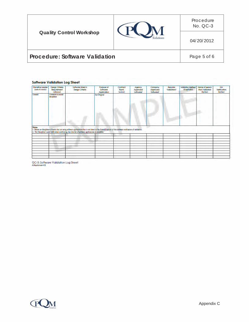
Quality Control Workshop
ProcedureNo. QC-3
04/20/2012
Procedure: Software Validation Page 5 of 6
Appendix C

Quality Control Workshop
ProcedureNo. QC-3
04/20/2012
Procedure: Software Validation Page 6 of 6
Appendix C

Quality Management Plan
Procedure No. QC-4
04/20/2012
Procedure: CADD Requirements Page 1 of 5
Appendix C
1.0 Purpose and Scope The purpose of this procedure is to provide the project CADD requirements prior to starting the design drawings. This requires that a CADD Manual be documented and confirmed that it meets the contract requirements and approving agency requirements.
2.0 Responsibility The Project Manager is responsible for contract compliance and negotiating any changes in the contract due to discrepancies found between the contract requirements and approving agency requirements.
The Design Manager is responsible for identifying any discrepancies between the contract requirements and approving agency requirements.
The Corporate CADD Manager (a senior CADD/IT Manager) will support the Project Manager in identifying the CADD requirements.
The CADD Manager oversees the day-to-day production of the drawings and manages a group of CADD operators and/or technicians that produce the drawings.
3.0 Definitions CADD: Computer Aided Design and Drafting
4.0 Process WorkflowThe CADD requirements setup process provides the workflow of the activities and coordination that takes place in developing the CADD Manual and user’s guide. The process follows the activities shown in the flowchart QC-4: CADD Requirements, see Attachment A
5.0 ProcedureThe procedure occurs in the Develop CADD Requirements phase and concentrates entirely on the ensuring that the designers have a functional CADD Manual and guidelines within the work environment that is effective and efficient for the entire design team regardless of their location.

Quality Management Plan
Procedure No. QC-4
04/20/2012
Procedure: CADD Requirements Page 2 of 5
Appendix C
5.1 Develop CADD Requirements PhaseThe team will start CADD production under the direction of the Design Manager and the Discipline Leaders. The CADD Manual and guideline will meet the requirements of the contract while also meeting the requirements of the reviewing and approving agency.
5.1.1 Input DataThe input data is information that is provided by the client as part of the contract. The project information, or data, are generally items like the previously prepared drawing files, survey files, contract requirements, design standards, design criteria, CADD Manuals, collaboration system, and completion requirements etc.
5.1.2 Compare Governing CriteriaThe Corporate CADD Manager will be responsible for locating the governing criteria that the project team will use when setting up electronic files. Information can typically be found in the Contract, Design Standards, Design Criteria, CADD Manuals, Document Control Guidelines and input from the Discipline Managers. All of the Approving Agency’s CADD Requirements will be checked to insure they meet the needs of the design team.
5.1.3 Review Requirements
The Corporate CADD Manager will review the CADD requirements and ensure compliance with the project configuration.
5.1.4 Identify Conflicts
The Corporate CADD Manager is responsible for identifying conflicts that may occur between the contract requirements, Agency CADD Manuals and the CADD configuration.
If there are no conflicts, proceed to prepare the CADD Users Guidelines. If conflicts exist, they will need to be resolved prior to completing the particular area of conflict for the CADD Users Guideline.
5.1.5 Resolve Conflicts
The Corporate CADD Manager will resolve conflicts with a client representative.
5.1.6 Prepare CADD Users Guidelines
Preparing the CADD Users Guidelines can begin early, but may not be completed until all of the conflicts are resolved. Project specific CADD Users Guidelines will be created by the Corporate CADD Manager.

Quality Management Plan
Procedure No. QC-4
04/20/2012
Procedure: CADD Requirements Page 3 of 5
Appendix C
5.1.7 Training Materials & Training Sessions The CADD Manager will prepare the CADD Training Materials necessary to properly train the CADD production staff. Additional training sessions will be created and conducted by the Corporate CADD Manager, as needed.
5.1.8 Document Training Sessions
The training materials and the sign-in sheet of the attendees will be maintained in the document control system and updated along with each modification or training session.
6.0 Referencesa. Project contract b. Applicable CADD Manuals
7.0 Attachmentsa. Attachment A: QC-4 CADD Requirements Flowchart b. Attachment B: Training Session Sign-in Sheet

Quality Management Plan
Procedure No. QC-4
04/20/2012
Procedure: CADD Requirements Page 4 of 5
Appendix C
Attachment A: QC-4 CADD Requirement Flowchart

Quality Management Plan
Procedure No. QC-4
04/20/2012
Procedure: CADD Requirements Page 5 of 5
Appendix C
Attachment B: Training Session Sign-in Sheet

Quality Management Plan
Procedure No. QC-5
04/20/2012
Procedure: Field Equipment Page 1 of 4
Appendix C
1.0 Purpose and ScopeThe primary purpose of this procedure is to ensure that manufacture or ASTM approved methods are being followed to ensure that technical field and laboratory equipment is properly maintained and calibrated at all times during use on the project.
2.0 Responsibility Discipline Leader (Survey, testing laboratories, environmental field equipment, etc.)
3.0 Definitions See definitions.
4.0 Process WorkflowA log sheet will be maintained, of the equipment that requires routine calibration and maintenance. It will be checked quarterly to coordinate the required maintenance in the following manner:
a. Add equipment to log sheet b. Check monthly for required maintenance c. Update log sheets, as equipment is calibrated and maintained
5.0 ProcedureField and laboratory equipment shall be maintained and calibrated in accordance with the manufacture’s recommendation. A log sheet, of the history of the equipment serial number and maintenance and calibration activity, shall be maintained in accessible and retrievable location for updating and monitoring. The log shall be reviewed monthly and updated accordingly.
6.0 Document ControlAll maintenance and calibration documentation, and supporting information for each piece of technical equipment used for this project shall be maintained in accordance with the Document Controls procedure.
7.0 AttachmentsAttachment A: QC-5: Field Equipment Flowchart

Quality Management Plan
Procedure No. QC-5
04/20/2012
Procedure: Field Equipment Page 2 of 4
Appendix C

Quality Management Plan
Procedure No. QC-5
04/20/2012
Procedure: Field Equipment Page 3 of 4
Appendix C

Quality Management Plan
Procedure No. QC-5
04/20/2012
Procedure: Field Equipment Page 4 of 4
Appendix C

Quality Management Plan
Procedure No. QC-6
04/20/2012
Procedure: Surveying and Mapping Page 1 of 11
Appendix C
1.0 Purpose and ScopeThe purpose of this procedure is to establish the process and requirements for preparing for field surveying, conducting the field surveying, and preparing the mapping that is used for planning and design activities.
2.0 Responsibility Survey Discipline Leader: a professional surveyor with a current surveyor license issues by the state where the project is located. This job classification may also be referred to as the Survey Manager.
Survey Supervisor: The Field Survey Supervisor provides the direction and manages one or more Party Chiefs.
Party Chief: the field leader responsible for collecting the field data under the direction of the Survey Discipline Leader
Field Surveyor: The Field Surveyor is responsible for all field activity including safety, use of equipment, accuracy of data collected and coordination with the Survey Supervisor and Survey Manager.
3.0 Definitions Design Survey: Field locating all of the existing features required for a designer to conduct a new design or improvement.
Cadastral Survey: A survey which creates, marks, defines, retraces or reestablishes the boundaries andSubdivisions of the public land of the United States.
Global Positioning System Survey: The Global Positioning System (GPS) is a space-based global navigation satellite system (GNSS) that provides reliable location and time information in all weather and at all times and anywhere on or near the Earth when and where there is an unobstructed line of sight to four or more GPS satellites. It is maintained by the United States government and is freely accessible by anyone with a GPS receiver. In addition to GPS other systems are in use or under development.
Construction Survey: Field locating construction elements from design documents for the purpose of construction.

Quality Management Plan
Procedure No. QC-6
04/20/2012
Procedure: Surveying and Mapping Page 2 of 11
Appendix C
4.0 Process Work FlowThe workflow process starts with an understanding of the scope of the services to be provided followed by research and preparation for the field activities. The data collected is used to either prepare base mapping or supplement existing base mapping which is used for planning and design.
Office Preparation Field Data Collection Base Mapping Preparation
5.0 ProcedureThe following procedures describe the instructions for three types of design surveys: Design, Cadastral and Global Positioning Systems (GPS). Instructions for construction surveying is provided and used only during the construction phase of the project. The Survey Discipline Leader will review the scope of work and provide direction to the survey team on the surveying and mapping activities requires for the task. Depending on the type of survey, one or more of the following will apply. Checking and maintaining the equipment is a common activity prior to each type of survey. Calibration and maintenance of equipment will follow Procedure QC-5 Field Equipment.
5.1 Design Surveys 5.1.1 The scope of work is provided by the Survey Manager and provided to the Party Chief. 5.1.2 Verify horizontal and vertical mapping datum with contract specifications. 5.1.3 Research the available or known field survey control at the governing jurisdictions. 5.1.4 Instrument calibration will be checked at the start of the daily work by the Party Chief. 5.1.5 The collected data will be downloaded daily and a plot check will be prepared and
reviewed by the Party Chief or designee. 5.1.6 The daily data is then forwarded to the CADD Department by the Party Chief. 5.1.7 The mapping is reviewed by the Party Chief and final field checks are completed, if
warranted. 5.1.8 The final survey data and mapping is approved by the Survey Manager.
5.2 Cadastral Surveying5.2.1 The scope of work is provided by the Survey Manager and provided to the Party Chief. 5.2.2 Verify horizontal and vertical mapping datum with contract specifications. 5.2.3 Research the available or known field survey control at the governing jurisdictions. 5.2.4 Instrument calibration will be checked at the start of the daily work by the Party Chief. 5.2.5 Instrument calibration check is done at the start of daily work by the Party Chief.

Quality Management Plan
Procedure No. QC-6
04/20/2012
Procedure: Surveying and Mapping Page 3 of 11
Appendix C
5.2.6 Redundant measurements are required for all terrestrial and global positioning surveys by the Party Chief.
5.2.7 Data will be post processed on a daily basis by the Party Chief. 5.2.8 The Party Chief or Survey Supervisor will check the data before being forwarded to the
CADD Manager. 5.2.9 The Party Chief and Survey Supervisor will check progress base maps for accuracy and
recommend approval of final survey data and mapping. 5.2.10 Final mapping is approved by the Survey Manager prior to being transmitted to the
designer.
5.3 GPS Surveying5.3.1 GPS Static and Fast-Static surveys are performed for the purpose of providing network
control for large scale construction projects, photogrammetric mapping and landnet retracement which generally follow the specifications of the state highway department. Check the controlling jurisdictional agency's website for the Survey Manual.
5.3.2 Data is post processed and adjusted with survey equipment software. See survey equipment instruction manuals.
5.3.3 Reference or control stations are chosen from the National Geodetic Surveys NAD83 (National Spatial Reference System 2007) National Readjustment list and the state’s High Precision Geodetic Network, where required. Proximity, GPS suitability, safety and network design are factors affecting the choice of stations.
5.3.4 Observation Data from continuously operating reference stations (CORS) is downloaded and integrated to the network. Where LEICA and CORS data is combined, the NGS calibration of antenna phase centers are used.
5.3.5 F and T statistical tests performed in the adjustment software and the report indicates the accuracy and precision of the control network.
5.3.6 Where GPS and conventional surveys are combined using agency approved and validated software. RTK (Real-Time-Kinematic) surveys are performed for the third-order work or lower.
5.4 Construction Surveying5.4.1 Field survey requests are received from the contractor by the Party Chief unless
different protocol has been established by the Survey Manager. 5.4.2 Construction plan version will be verified by the Party Chief with the contractor's
superintendent prior to starting work.
Quality Management Plan
Procedure No. QC-6
04/20/2012
Procedure: Surveying and Mapping Page 4 of 11
Appendix C
5.4.3 Instrument calibration will be done at the start of daily work by the Party Chief. 5.4.4 Coordinates for stakeout will be plot checked and cut sheets will be checked by the
chainman under the direction of the Party Chief. 5.4.5 Daily stakeout files will be downloaded and placed in the survey transfer folder by the
Party Chief. 5.4.6 Coordinates and dimensions on plans will not be scaled, except for rough grade stakes
and will be performed by the Party Chief.
5.5 Datums5.5.1 The National Standard for Spatial Data Accuracy (NSSDA) methodology is used to test
the positional accuracy of geo-referenced maps and digital geospatial data. 5.5.2 The test is used to determine the conformance levels or accuracy threshold of
standards, such as National Map Accuracy Standards of 1947 or Accuracy Standards for Large-Scale Maps [American Society for Photogrammetric and Remote Sensing (ASPRS) Specifications and Standards Committee, 1990].
5.5.3 Accuracy is tested by comparing the planimetric coordinates of well-defined points in the data set with coordinates of the same points from an independent source of higher accuracy.
5.5.4 A minimum of 20 check points are tested, spread throughout the project, and accuracy is reported at the 95% confidence level.
5.5.5 Where the accuracy is required to conform to the older standard NMAS a 90% confidence level is calculated for both, the horizontal and vertical data, where the horizontal tolerance is 1/30 inch for map scales larger than 1:20,000 and 1/50 inch for map scales smaller then 1:20,000 and the vertical tolerance is 12 the contour interval at all contour intervals.
5.6 Survey EquipmentThe Survey Manager will provide a complete list of survey equipment.
5.7 Base Map Preparation5.7.1 Preparation
Survey computations are performed under the direction of the Survey Manager or designee. The scope of work provides the description of the work to be accomplished. The Survey Manager will confirm the Designers mapping requirements and within the applicable state laws, including the following:
a. Mapping type, size and format b. Mapping Type

Quality Management Plan
Procedure No. QC-6
04/20/2012
Procedure: Surveying and Mapping Page 5 of 11
Appendix C
c. Approximate numbers of drawings d. Mapping standards e. Mapping numbering requirements f. Requirements for sealing the mapping g. Requirements for using CADD standards h. Agency required CADD software i. Deliverable mapping requirements j. Material requirements k. Special requirements
The Survey Manager is responsible for implementing the surveying and mapping requirements and producing the base mapping for the designers consistent with the electronic and CADD requirements.
5.7.2 Mapping, Checking and Reviewing
The Survey Manager will continually coordinate the mapping produced on a basis with regard to the following:
a. Project design requirements b. Owner's requirements c. Other discipline's requirements d. Revisions which affect the other discipline's mapping e. Contract specifications f. Regulatory agency requirements g. Client mapping standards
As field mapping reaches a status of completion suitable for checking will be completed in accordance with the applicable procedures for checking calculations and drawings (QC-7 and QC-8 respectively). In addition, a Discipline and Inter-Discipline Review will be conducted in accordance with the Design Review Program (QC-11).
If the mapping product requires conversion from AutoCAD to Microstation, the CADD technician will follow the "Check List for Drawing Conversion from AutoCAD to Microstation. See Attachment B.
5.7.3 Field Verification of Mapping and Approval
The Survey Manager will conduct a Management Review in accordance with the Design Review Program (QC-11) prior to distribution or transmitting the base mapping to the Designer. The

Quality Management Plan
Procedure No. QC-6
04/20/2012
Procedure: Surveying and Mapping Page 6 of 11
Appendix C
surveyor will check and review the data transfer to the mapping for accuracy and reasonableness. In addition, an independent senior reviewer shall check the final maps for completeness and accuracy. Any necessary revisions or corrections will be made in accordance with this procedure prior to the quality certification.
5.7.4 Designer Review
The Designer will be requested to review the mapping for contract mandated requirements. Comments from the Designer will be prepared and provided to the Survey Manager to address and revise the mapping accordingly.
5.7.5 Map Revisions
Upon receipt of the mapping review comments the Survey Manager will evaluate the comments and respond accordingly. The maps, data, check points and check prints will be archived. The Survey Manager will respond to the comments and revise the mapping as required. All revisions will be checked for accuracy and in accordance with the Design Review Program (QC-11) and this procedure.
5.7.6 Final Mapping
The Survey Manager shall deliver completed drawings along with a written statement certifying that has performed all corrections/additions as agreed during review process by the Senior Project Manager or Manager, Field Survey Team and the Client. The following sentence shall be included in this written statement "The (substitute name of deliverable document) has been checked by a qualified individual other than the originator. Copies of submittals shall be provided to the Client.
All maps, data, check points and check points will be stored on the electronic management data system per the document control procedure. Subsequent versions of mapping shall be identified by an incremental version and noted by name in the revision block.
5.7.7 Quality Certification
The Survey Manager will certify that the base mapping meets the scope of work, accuracy and electronic compatibility and configuration required by the contract. The Quality Assurance Manager will certify that the quality control process preparation, checking and reviewing requirements were properly followed.

Quality Management Plan
Procedure No. QC-6
04/20/2012
Procedure: Surveying and Mapping Page 7 of 11
Appendix C
6.0 Document ControlThe survey data and base mapping shall be maintained in accordance with the approved document control procedure.
7.0 Referencesa. QC-3: Software Validation b. QC-4: CADD Requirements c. QC-5: Field Equipment d. QC-7: Checking Calculations e. QC-8: Checking Drawings f. QC-11: Design Review Program
AttachmentAttachment A: Field Surveying & Mapping Flowchart Attachment B: Checklist for Drawing Conversion from AutoCad to Microstation Attachment C: Survey Certification

Quality Management Plan
Procedure No. QC-6
04/20/2012
Procedure: Surveying and Mapping Page 8 of 11
Appendix C
Attachment A: QC-6: Field Surveying & Mapping Flowchart

Quality Management Plan
Procedure No. QC-6
04/20/2012
Procedure: Surveying and Mapping Page 9 of 11
Appendix C
Attachment B
CHECK LIST FOR DRAWINGS CONVERSIONS
FROM AUTOCAD TO MICROSTATIONProject Number: ______________ Client: ________________
Drawing Number: _____________ Date: _________________
1. Check that nothing disappeared during conversion. [ ]
a. Compare the AutoCAD to the Microstation Drawing.
2. Check that you are using the correct seed file. [ ]
a. This will be specified by the Client.
3. Check that you have correct Global Origin [ ]
a. This will be specified by the Client.
4. Check that you are using the correct working units. [ ]
a. Such as U.S. Survey Feet.
5. Check that your coordinates are correct. [ ]
a. Compare with ASCII file or AutoCAD Drawing.
6. Check that elevations are correct. [ ]
a. See 3d view and check lines and points.
7. Check that your levels are correct. [ ]
a. This will be specified by the Client.
8. Check that the line styles are correct. [ ]
a. This will be specified by the Client.
9. Check that your fonts are correct. [ ]
a. This will be specified by the Client.
10. Check that your colors are correct. [ ]
a. This will be specified by the Client.

Quality Management Plan
Procedure No. QC-6
04/20/2012
Procedure: Surveying and Mapping Page 10 of 11
Appendix C

Quality Management Plan
Procedure No. QC-6
04/20/2012
Procedure: Surveying and Mapping Page 11 of 11
Appendix C

Quality Management Plan
Procedure No. QC-7
04/20/2012
Procedure: Checking Calculations Page 1 of 17
Appendix C
1.0 Purpose and ScopeThe purpose of this procedure is to provide a uniform method and format for preparing and checking calculations. The procedure defines the requirements for preparing, checking, revising, approving and the retention of calculations. This procedure describes the method for checking calculations prepared during planning, design, and field engineering changes for calculations prepared manually and those prepared using a computer software program. This procedure applies to design, analysis, cost estimates, numerical tables, etc., regardless if the calculations are prepared manually, or computer generated. This accuracy check procedure is completed during the design development phase.
2.0 Responsibility Discipline Leader or designee
3.0 Definitions Assumptions: The supposition that the information used is correct in order to proceed with the calculations despite some technical uncertainties.
Calculations: Calculations or sets of calculations are generated using industry accepted methods and lead to a conclusion then used to justify the design decisions and drawings accuracy.
Independent Check: The independent check method of performing and checking calculations is a method where the design and analysis is completed by an Originator; then the design is provided to a qualified person (Independent Checker) to perform an independent set of calculations or analysis of the design which is checked against the Originators design.
Final Calculations: The final calculations are calculations or a set of calculations that have been checked and approved by the Discipline Leader.
Preliminary Calculations: The preliminary calculation is calculations or a set of calculations that have been prepared by a competent engineer or technician but have not been checked and approved.

Quality Management Plan
Procedure No. QC-7
04/20/2012
Procedure: Checking Calculations Page 2 of 17
Appendix C
4.0 Process WorkflowThere are three phases in the preparing and checking calculation process.
Phases of calculation development:
1. Scope of Work and Assign
2. Prepare Calculations.
3. Accuracy Check
The accuracy checks will follow this process:
Prepare Check Back Check Update Verify
5.0 Procedure (Attachment A)
The calculations described in these procedures include manually prepared, spreadsheets, math simulation models, or design software applications. Manually prepared calculation are prepared using pencil on paper and a hand held calculator to assist in performing the mathematical calculations and self checks.
Computer software applications must be validated in accordance with the Software Validation Procedure QC – 3.
Preparing and checking calculations occurs in three phases regardless if they are prepared manually or computer generated:
1. Developing the scope of work for the calculations and assigning to a qualified designer. 2. Preparing the calculations in accordance with the scope of work, design criteria; and
standards. 3. Conducting the calculation accuracy and reasonableness checks using the Color Code
System described in the Design Protocol Procedure (QC-1).
These phases are described in the following sections.
5.0.1 Scope of Work and Assign CalculationsA detailed scope of work will be prepared under the supervision of the Discipline Leader. The scope of work will include sufficient information, such as, the intent of the calculations, available data, previous assumptions and methodology used, design criteria, standards, etc. for the calculations to be performed. A qualified professional will be assigned to perform the work.

Quality Management Plan
Procedure No. QC-7
04/20/2012
Procedure: Checking Calculations Page 3 of 17
Appendix C
In the initial phase of preparing the calculations the Discipline Leader or designee will determine which calculations are prepared manually or prepared using a computer software application. Frequently, both methods are used to perform the analysis. The approach should be discussed in the scope of work.
1. Manually Prepared Calculations.
2. Computer Generated Calculations.
3. Independent Check of Calculations.
5.0.2 Prepare Calculations
Calculations may be developed using a manual or computer generated method and is at the sole discretion of the Discipline Leader or designee.
5.0.3 Conduct Accuracy Check
The method used to perform the accuracy check of the calculations will depend on the method used to perform the calculations.
1. Line-by-line check is used to check manually prepared calculations and spreadsheet calculations.
2. Input-Output checks are used to check calculations prepared by a design software application.
3. Independent check is often used for structural design checks.
Each of these check methods are further described in this procedure for checking calculations.
5.1 Manually Prepared Calculations (Attachment B)
5.1.1 Prepare CalculationsCalculations are originated by an architect, engineer, scientist or technician who is called the “Originator”.
The Originator shall:
a. Prepare preliminary calculations using 8-1/2” x 11” calculation paper designated for the project.
b. Calculations shall be neat, orderly, legible, and presented within the margins of the paper.

Quality Management Plan
Procedure No. QC-7
04/20/2012
Procedure: Checking Calculations Page 4 of 17
Appendix C
c. Prepare calculations using graphite lead, sufficiently dark enough to photocopy and the title block shall be complete on each sheet stating the project title, calculation title, name or initials of the originator and checker, and dated.
d. Clearly define the problem statement and approach or methodology. e. Describe the inputs, design criteria, manuals, guidelines and methodology to support
the calculation preparation. f. Clearly state all assumptions and provide sufficient support for making each assumption.
Minimize the assumptions to only ones that are agreeable not verifiable and are common assumptions for the particular approach or methodology.
g. Site references such as manuals, guidelines and methodology that support the preparation of the calculations.
h. Provide sketches as necessary to accurately illustrate the problem and solution. i. Show derivation of equations or attach copy of reference equation. j. Clearly show units of measure and mathematical conversions. k. Clearly show conclusions using a consistent distinguishable designation such as drawing
a box around the results. l. Provide a brief conclusion and recommendation. m. Develop calculations in a consecutively numbered and indexed manner and shall be
arranged orderly and with only current calculation in a 3-ring notebook with dividers, as necessary.
n. Clearly label the notebook with the project name, element of work and dated accordingly.
o. “Void” calculations that have been voided or superseded and note accordingly.
p. Scan final calculations to be maintained as part of the project electronic files.
q. Print or copy the original set of calculations to be used as the Check Set. The Check Set will be stamped with the “Check Print” stamp, numbered, initialed, and date as the Originator on the cover page of each section of calculations.
r. Provide the stamped (Check Print stamp) Calculation Check Set to the Checker.
5.1.2 Prepare Calculation PackageThe Originator will prepare a copy of a complete calculation package and stamp the cover with the Check Print Stamp and initial and date as the Originator.
5.1.3 Check CalculationsThe Checker shall:

Quality Management Plan
Procedure No. QC-7
04/20/2012
Procedure: Checking Calculations Page 5 of 17
Appendix C
a. Check preliminary calculations using the Color Code System in QC-1. b. Check and confirm that the calculations are prepared using the proper calculation
paper, format, etc. c. Check approach, methodology, assumptions, sketches, calculations and conclusion. d. Check each calculation for logic and accuracy. e. Check each formula used to perform the calculation. f. Check drawing against calculations and calculations against drawings for consistency
and accuracy. Note: Often the results from the calculations are used for dimensions, sizes , slopes, etc. on drawings. The check will extend to confirm that the calculations and drawing information is accurately transcribed to the drawings. This is also a part of the Checking Drawings Procedure.
5.1.4 QC Stamp (Both Calculations and Drawings)a. Initial and date the “Drawings checked against calculations and calculation checked
against drawings confirmed” ONLY if drawings and calculations have been checked and confirmed. If there are no calculations required to check or if the calculations and drawings are performed within the software application system, then note not applicable by writing “N/A”.
b. Initial and date Check Print stamp as the Checker. c. Return the preliminary calculation check set (redline set) to the Originator to evaluate
the review comments.
5.1.5 Evaluate Review CommentsThe Back Checker is preferred to be the Originator unless faced with extraordinary circumstances, then an engineer or technician with comparable skills may serve as the Originator. The Back Checker shall:
a. Back Check the calculation check set. b. Evaluate the Checker's comments. c. Initial and date the Check Print Stamp as Back Checker.
5.1.6 Resolve Comments a. The Back Checker (Originator) will discuss any disagreements with the Checker and
resolve as appropriate. If agreement cannot be concluded then the decision shall be
Quality Management Plan
Procedure No. QC-7
04/20/2012
Procedure: Checking Calculations Page 6 of 17
Appendix C
elevated to the Discipline Leader who shall resolve and provide direction on how to move forward.
b. If a decision still cannot be resolved with the Discipline Leader then the issue will be elevated to the Quality Control Manager who will identify a Subject Matter Expert to determine the resolution and provide direction on how to proceed.
5.1.7 Update Calculationsa. The original calculations will be updated per the redline set. b. Show the corrections have been made to the original calculations. c. Initial and date Check Print stamp as the “Updater”. d. Provide the Original Calculations and Calculation Check Set to the Verifier to confirm
that each comment/correction was properly responded to.
5.1.8 Verify Updated CalculationsThe Verifier is preferred to be the Checker unless faced with extraordinary circumstances, then an engineer or technician with comparable skills may serve as the Verifier. The Verifier shall:
a. Confirm that all updates fully and completely comply with the resolutions. b. If the calculation updates do not fully and completely comply with the resolutions, then
both sets shall be returned to the Originator to complete the work. c. The same process will continue until the Verifier can fully and completely verify that the
resolutions have been accurately updated. If this persists, the Discipline Leader and Design Manager shall be notified. The Verifier will initial and date upon full agreement that the comments are satisfied.
5.1.9 QC StampIf the updates correctly represent the final resolutions, the Verifier will initial and date as Verified. The Verifier returns the Final Calculations and Calculation Check Set to the Originator.
5.1.10 Quality Records The checked calculations are quality records and must be file in accordance with the designated quality records instructions.

Quality Management Plan
Procedure No. QC-7
04/20/2012
Procedure: Checking Calculations Page 7 of 17
Appendix C
5.2 Checking Computer Generated Calculation (See Attachment C)The software application must be validated prior to checking the input and output as described in this section.
Calculation generated from proprietary software must be checked. A hardcopy printout of the computer generated calculations shall be provided. The Checker must have access to the software application used, including access to the raw formulas used to generate the calculation and data file.
Under this scenario, the input data is checked in detail and the output is check for reasonableness. Discipline Leader: The Discipline Leader will designate a Checker to check the calculations. The Discipline Leader will approve the software applications used to develop the calculations and/or analysis. Assign Checker The Discipline Leader will designate a Checker(s) to review all preliminary calculations prepared in accordance with the scope of work and the design criteria.
5.2.1 Prepare Calculations Prepare Manual calculations per Section 5.4.
5.2.2 Prepare Calculation PackagePrepare calculations in accordance with the scope of work and intended analysis.
5.2.3 Confirm Software ApplicationSee QC – 3: Software Validation as necessary.
5.2.4 Check CalculationsThe Checker shall:
a. Check preliminary calculations using the Color Code System in the Design Protocol Procedure QC-1.
b. Check and confirm that the calculations are prepared using the proper calculation paper, format, etc.
c. Check approach, methodology, assumptions, sketches, calculations and conclusion. d. Check each input data.

Quality Management Plan
Procedure No. QC-7
04/20/2012
Procedure: Checking Calculations Page 8 of 17
Appendix C
e. Verify that software or spreadsheet is appropriate for the calculations and conclusion (if applicable).
f. Check input, output, approach, methodology, assumptions, sketches, calculations and conclusion.
g. Check each formula used to perform the preliminary calculation Spot check the output. h. Check drawing against calculations and calculations against drawings for consistency
and accuracy. i. Initial and date the “Drawings checked against calculations and calculation checked
against drawings confirmed” ONLY if drawings and calculations have been checked and confirmed. If there are no calculations required to check the drawing then note that it is not applicable by writing “N/A”.
j. Initial and date Check Print stamp as the Checker.Note: Often the results from the calculations are used for dimensions, sizes, slopes, etc. on drawings. The check will extend to confirm that the calculations and drawing information is accurately transcribed to the drawings. This is also a part of the Checking Drawings procedure.
k. Return the preliminary calculation Check Set (redline set) to the Originator.
5.2.5 Prepare Review CommentsPrepare the review comments on a comment response log sheet. It is acceptable to attach redlined markups as a reference.
5.2.6 Evaluate Review CommentsThe Originator will evaluate the review comments and respond accordingly.
5.2.7 Resolve CommentsResolve the comments with the Checker. Refer to the comments resolution procedure noted in the QC – 1: Design Checking Protocol.
5.2.8 Update Calculations Update the calculations in accordance with the design criteria.
5.2.9 Verify Updated DesignThe Verifier will update the calculations as agreed during the comment resolution.
5.2.10 QC StampComplete the Check Print Stamp

Quality Management Plan
Procedure No. QC-7
04/20/2012
Procedure: Checking Calculations Page 9 of 17
Appendix C
5.2.11 Quality RecordsThe checked calculations are quality records and must be filed in accordance with the designated quality records instructions.
5.3 Independent Check of Calculations (Attachment D)The Discipline Leader will designate a Checker(s) to review all preliminary calculations prepared in accordance with the scope of work and the design criteria. Calculations and independent check calculations shall be assigned to a competent engineer or technician with sufficient knowledge, education, or experience in a similar area of structures design.
The Independent Check takes place when the structural plans are developed to a 60% design level and prior to the 100% design. This approach has two primary paths that may occur concurrently. The Originator will provide the Independent Checker with the design drawings and design criteria to perform the Independent Check. The Independent Checker will not be provided the design calculations. The Independent Checker will use the information provided to develop the analysis and independent set of calculations. Once the independent set of calculations is complete, the drawings will be “Redlined” noting the discrepancies, issues or concerns on the provided drawings. The drawings and calculations are provided to the Originator.
If the original calculations require updating they will be checked using the following checking process:
Check Back Check Updated Verify
5.3.1 Prepare DesignThe Originator shall:
a. Consult with the Discipline Leader on the readiness of the submittal package.
b. The calculations and drawings shall be prepared in accordance with the design criteria.
c. Arrange the Structural Drawings and all reference materials to be provided to the Independent Checker to conduct their review.
d. Each sheet (drawing) of the structures design package will be stamped with the “Check Print” stamp.
e. Number, initial, and date each stamp in the appropriate locations as the Originator.
f. Provide the stamped drawings and appropriate reference materials to the Independent Checker to perform their review.

Quality Management Plan
Procedure No. QC-7
04/20/2012
Procedure: Checking Calculations Page 10 of 17
Appendix C
g. The Originator's calculations shall not be provided to the Independent Checker.
h. Develop calculations using the same drawings and review materials provided to the independent Checker.
5.3.2 Prepare Plan Set PackagePrepare the complete check package and provide to the Independent Checker.
5.3.3 Independent Check AnalysisThe Discipline Leader will designate an “Independent Checker(s)” to perform a detailed analysis of the structural calculations in accordance with the design criteria for the project. The Independent Checker will be a person different than the Originator and of equal or more experience in structures design on similar type of structures.
The Independent Checker shall:
a. Review the General Notes for conformance with the scope of work for the project. b. Determine the approach, methodology, assumptions, sketches, studies, etc. that were
considered for development of each structure. c. Perform a detailed analysis and produce a set of independent calculations in accordance
with the drawings provided and using the design criteria. The independent set of calculations will be kept as a permanent record in a separate independent check calculation book.
d. Check independent calculations against drawing and drawing against calculations for consistency and accuracy; the drawings shall be marked for agreement and correction, and make notes on the drawings to the Originator.
e. Notify the Originator of any discrepancy or nonconformance if a portion of the design is not in agreement with the independent calculation check or not in conformance with the Design Criteria or studies developed for the project.
f. Initial and date the Check Print Stamp “Check calculations against drawings and drawings against calculations confirm” space ONLY if drawings and calculations confirm. If there are no calculations required to check the drawing then note that it is not applicable by writing “N/A”.
g. Initial and date Check Print Stamp as the Checker. h. Return the independent calculations check set to the Originator to back check the
comments.
5.3.4 Prepare Redlines and Review Comments
Quality Management Plan
Procedure No. QC-7
04/20/2012
Procedure: Checking Calculations Page 11 of 17
Appendix C
Graphically represent the review comments on a copy of the identical design documents provided to the Independent Checker. Markup per design documents per the Color Code System, if not completed.
5.3.5 Evaluate Review CommentsThe Back Checker is preferred to be the Originator unless faced with extraordinary circumstances, then an engineer or technician with comparable skills may serve as the Originator.
The Back Checker shall:
a. Evaluate the calculation results developed by the Independent Checker compared to the Calculation Check Set developed by the Originator. Note any discrepancies, inconsistencies or inaccuracies that are not within acceptable tolerances of the design using the Color Code System.
b. Maintain the Independent Check calculations as a permanent record in a separate calculation notebook.
c. Update the original design per the red marks on the calculations and drawings. d. Initial and date the Check Print Stamp as Back Checker. e. Provide the Calculations Check Set and the Independent Calculation Check Set and all
relevant comments/mark-ups to the Verifier to confirm that each comment/correction was properly incorporated.
5.3.6 Resolve Commentsa. Back Checker (Originator) will discuss any disagreements with the Independent Checker
and resolve as appropriate. If agreement cannot be concluded then the decision shall be elevated to the Discipline Leader who shall resolve and provide direction on how to move forward.
b. If a decision still cannot be resolved with the Discipline Leader then the issue will be elevated to the Quality Control Manager who will identify a Subject Matter Expert to determine the resolution and provide direction on how to proceed.
c. Back Checker will write out the comment and resolution.
5.3.7 Update Calculations and Designa. The calculations will be updated per the agreement and/or resolution. b. Initial and date Check Print stamp as the “Updater”.

Quality Management Plan
Procedure No. QC-7
04/20/2012
Procedure: Checking Calculations Page 12 of 17
Appendix C
5.3.8 Verify Updated DesignThe Verifier is preferred to be the Checker unless faced with extraordinary circumstances, then an engineer or technician with comparable skills may serve as the Verifier.
The Verifier shall:
a. Confirm that all updates fully and completely comply with the resolutions. If the updates correctly represent the resolutions the Verifier will initial and date as "Verified." The Verifier returns the Original Final Calculations and Independent Calculations to the Originator.
b. If the calculation updates do not fully and completely comply with the resolutions, then both sets shall be returned to the Discipline Leader and the Originator shall be notified of the status. The Verifier will not initial and date.
c. The same process will continue until the Verifier can fully and completely verify that the resolutions have been accurately updated.
5.3.9 Prepare Final DesignPrepare the final design in accordance with the design criteria and prepare the specifications required for the design in accordance with QC – 10, Checking Specifications.
5.3.10 Check Final DesignCheck final design in accordance with this procedure.
5.3.11 File Quality RecordsFile the quality records in the proper directory assigned for this Submittal Version.
6.0 Document ControlQuality Records Quality Records shall be maintained in accordance with the Document Control procedures. Originator The Originator shall:
a. Copy and file each section of the Checked Set of calculations and a clean copy of the final calculations. The checked calculations(s) are Quality Records and shall be maintained as designated by the Document Control procedure.
b. An electronic copy of the final calculations shall be stored as designated by the Document Control procedures.

Quality Management Plan
Procedure No. QC-7
04/20/2012
Procedure: Checking Calculations Page 13 of 17
Appendix C
7.0 ReferencesQC-1: Design Protocol QC-3: Software Validation QC-8: Preparation and Checking Drawings
AttachmentsAttachment A: QC-7: Preparing and Checking Calculation FlowchartAttachment B: QC-7a: Line-by-Line Calculation Check Flowchart Attachment C: QC-7b: Checking Computer Generated Calculations Flowchart Attachment D: QC-7c: Independent Calculation Check Flowchart

Quality Management Plan
Procedure No. QC-7
04/20/2012
Procedure: Checking Calculations Page 14 of 17
Appendix C
Attachment A: QC-7: Preparing and Checking Calculation Flowchart

Quality Management Plan
Procedure No. QC-7
04/20/2012
Procedure: Checking Calculations Page 15 of 17
Appendix C
Attachment B: QC-7a: Line-by-Line Calculation Check Flowchart

Quality Management Plan
Procedure No. QC-7
04/20/2012
Procedure: Checking Calculations Page 16 of 17
Appendix C
Attachment C: QC-7b: Checking Computer Generated Calculations Flowchart

Quality Management Plan
Procedure No. QC-7
04/20/2012
Procedure: Checking Calculations Page 17 of 17
Appendix C
Attachment D: QC-7c: Independent Calculation Check Flowchart

Quality Management Plan
Procedure No. QC-8
04/20/2012
Procedure: Preparation and Checking Drawings Page 1 of 6
Appendix C
1.0 Purpose and ScopeThe purpose of this procedure is to define the requirements for preparing, checking, revising, and approving of computer aided drawings. Drawings shall be prepared in accordance with the applicable design criteria, standards, CADD User’s Manual, contract requirements; and the work products shall be checked and reviewed as necessary to achieve a high quality and low risk design product. This procedure is an accuracy check procedure and completed during the design development phase.
2.0 Responsibility Discipline Leader or designee is responsible for the technical accuracy and completeness of the drawings within their particular discipline of work; and assign qualified professionals to originate and check the drawings. The CADD Manager has the responsibility to ensure that the drawings are prepared in accordance with the CADD User's Manual, contract requirements and approving agencies' format guidelines.
3.0 Definitions Check Print: A drawing that is stamped with a “Check Print” stamp and goes through the check drawing process.
Checked Drawing: A checked drawing is a plan sheet that has either gone through the checking process or has been checked, back checked, updated and verified. A checked drawing is a quality record.
Clean Sheet: A Clean Sheet is a copy of an updated drawing that accurately reflects all of the redline corrections on the Check Print markups.
Drawings: A drawing is an illustration with a graphical scaled representation of an architectural or engineered design that is used to present physical objects such as: configuration location, size dimensions, elevations, and materials. Drawings may be presented as schematics, diagrams or as a scaled plan, profile, or elevation.
Sketch: A sketch is a drawing that presents architectural or engineered concepts and may or may not be to scale.
Redline Markup: A Redline Markup drawing is one that shows the Checkers, Back Checker’s, and Updater’s marks and comments on the drawing.

Quality Management Plan
Procedure No. QC-8
04/20/2012
Procedure: Preparation and Checking Drawings Page 2 of 6
Appendix C
Set of Drawings: Several individual drawings make up a set of drawings.
4.0 Process WorkflowThe Checking Drawings flowchart process provides a detailed workflow of the activities and coordination that takes place between those involved in the originating and checking process. The design product is prepared by a qualified professional followed by a formal quality control checking phases, as shown below:
Design Development Design Checks The process requires that a minimum of two people be involved in the process:
a. Originator (A) b. Checker (B) c. Back Checker, Originator (A) d. Updater (A or C), could be the Originator or a CAD Technician e. Verifier, Back Checker (B)
The following steps will be followed:
Originate Check Back Check Update Verify This is further detailed in the Preparation and Checking Drawings Process on the following page.
5.0 RequirementsThese requirements are prepared for an electronic Computer Aided Design and Drafting (CADD) work environment. Add-on software applications that perform the design calculations and drawing simultaneously are frequently used and acceptable, as long as they meet the Software Validation Procedure requirements.
Color Code System
a. Check Print Stamp
b. Assign Qualified Staff
c. Adjudication
5.1 Drawing Development Drawings are originated by an architect, engineer or qualified technician working under the direction of the Discipline Leader or designee. The Discipline Leader shall designate a qualified Checker for each drawing or set of drawings. The Originator (A) shall:

Quality Management Plan
Procedure No. QC-8
04/20/2012
Procedure: Preparation and Checking Drawings Page 3 of 6
Appendix C
a. Confirm with the CADD Manager the computer automated design and drafting (CADD) standards meet the contract requirements, criteria, text, graphics, CADD levels, style, and type required by the owner of the CAD files.
b. All drawings shall be neat and legible, and prepared in accordance with the CADD guidelines. The designer is encouraged to use a design criteria and standards checklist during the preparation of design drawings.
c. Coordinate with the Discipline Leader or designee, as necessary to accurately present the drawing information.
d. Self Check: Conduct a check of your own work, to the best of your ability, prior to advancing the drawing(s) to the formal checking process.
Formal Check
The Originator shall:a. Stamp each drawing to be checked with the Check Print Stamp. b. Place the number and date at the top of the Check Print stamp on all sheets. c. Initial and date, as the Originator of the drawing(s). d. Provide all relevant reference materials and calculations necessary to perform the
review.
Note: calculations shall be checked prior to checking the drawings. It may be the Originators intent for the Checker to check both the calculation(s) and drawing(s). In this case, the Checking Calculations Procedure applies and shall be completed prior to checking the drawings.
5.2 Drawing Check
Checker (B) The Checker shall:
a. Calculations shall be checked prior to checking drawings, when applicable. i. Check calculations against drawing and drawing against calculations to confirm,
items such as, slopes, sizes, dimensions, etc. are correctly shown. ii. Initial and date the “Check calculations against drawings and drawings against
calculations confirmed” ONLY if drawings and calculations confirm. iii. If there are no calculations required to check the drawing then note that it is not
applicable by writing “N/A”. b. Conduct a detailed check on each drawing for accuracy, consistency, completeness and
reasonableness; design criteria and standards; and drafting requirements. c. Initial and date Check Print stamp as the Checker.
Quality Management Plan
Procedure No. QC-8
04/20/2012
Procedure: Preparation and Checking Drawings Page 4 of 6
Appendix C
d. Return the check print drawings, calculation and reference material to the Originator.
5.3 Back Check Drawings
The Back Checker (B) is preferred to be the Originator (A) unless faced with extraordinary circumstances and then a person with comparable skills and familiarity with the design may serve as the Back Checker. The Back Checker will:
a. Use the color symbols designated by the Color Code System. b. Respond to any notes made by the Checker. c. Initial and date the Check Print Stamp as the “Back Checker”. d. In the event of a disagreement, see Design Protocol, “Adjudication”
5.4 Update Drawings
Updater (A or C) The Updater shall:
a. Use the color symbols designated in the color code system. b. Review the Check Print markups to understand the required updates. Seek out
clarifications from the Originator, as necessary, prior to updating the drawing. c. Update the electronic drawing files (CADD) as shown on the Check Print drawing(s). d. Print out a Clean Sheet and confirm that the updates are properly incorporated. Correct
as necessary. e. Initial and date the Check Print stamp as the Updater. f. Return the Check Print and Clean Sheet to the Verifier (B).
5.5 Verify Drawing Revisions
The Verifier is preferred to be the Checker unless faced with extraordinary circumstances, and then a person with comparable skills may serve as the Verifier. The Originator (A) may verify the drawing revisions, only if the Updater and Verifier are different people, otherwise the Verifier shall confirm the updates. The Verifier (B) shall:
a. Use the color symbols designated in the Color Code System. b. Verify that the redline on the Check Print are accurately updated on the Clean Sheet. c. If the Clean Sheet(s) do not fully and completely comply with the Check Print, then they
shall be returned to the Originator and notified that the revisions are inconsistent with
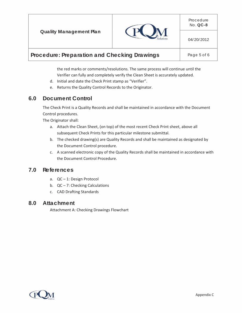
Quality Management Plan
Procedure No. QC-8
04/20/2012
Procedure: Preparation and Checking Drawings Page 5 of 6
Appendix C
the red marks or comments/resolutions. The same process will continue until the Verifier can fully and completely verify the Clean Sheet is accurately updated.
d. Initial and date the Check Print stamp as “Verifier”. e. Returns the Quality Control Records to the Originator.
6.0 Document ControlThe Check Print is a Quality Records and shall be maintained in accordance with the Document Control procedures. The Originator shall:
a. Attach the Clean Sheet, (on top) of the most recent Check Print sheet, above all subsequent Check Prints for this particular milestone submittal.
b. The checked drawing(s) are Quality Records and shall be maintained as designated by the Document Control procedure.
c. A scanned electronic copy of the Quality Records shall be maintained in accordance with the Document Control Procedure.
7.0 Referencesa. QC – 1: Design Protocol b. QC – 7: Checking Calculations c. CAD Drafting Standards
8.0 Attachment Attachment A: Checking Drawings Flowchart

Quality Management Plan
Procedure No. QC-8
04/20/2012
Procedure: Preparation and Checking Drawings Page 6 of 6
Appendix C
Attachment A: Checking Drawings Flowchart

Quality Management Plan
Procedure No. QC-9
04/20/2012
Procedure: Preparation and Checking Reports Page 1 of 8
Appendix C
1.0 Purpose and ScopeThe purpose of this procedure is to define the requirements for preparing, checking, revising, and approving technical reports and studies. Reports shall be prepared in accordance with the applicable contract requirements, and/or agency guidelines.
2.0 Responsibility Discipline Leader or designee is responsible for the technical accuracy, completeness, consistency and methodology for reports and studies.
3.0 Definitions Studies may be classified as informal or formal depending on the type of study and subject matter. Documentation requirements may range from an informal memorandum for an informal study to a complete detailed analysis report for a formal study.
Formal Studies: Formal studies are those performed to investigate concepts or to develop criteria that define the project scope and presented in a specific format. It usually requires a wider circulation of reviewers and approvals than that an informal report.
Informal Study: An informal study is one that is developed for the project design and within the scope of the contract. Typically they are performed as a matter of course to define physical aspects, resolve problems or to investigate new or improved methods, materials or processes.
Report: A Report is the compilation of the study findings with the conclusion and recommendation clearly stated. A Report is professionally bounded with complete content and references that lead to the findings, conclusions and recommendations.
Study: A Study is an assessment of scientific, engineering or empirical data and other relevant characteristics and factors that are evaluated in whole by an experienced scientist or engineer that leads to a conclusion and recommendation for a specific subject or outcome.
4.0 Process WorkflowThe Checking Reports process, provides a detailed workflow of the activities and coordination that takes place between those involved in the originating and checking process. The workflow process follows these steps indicated here, which are also shown across the top of the flowchart. Develop Initial Report Coordination & Draft Report

Quality Management Plan
Procedure No. QC-9
04/20/2012
Procedure: Preparation and Checking Reports Page 2 of 8
Appendix C
Review & Update Final Draft Report Final Report
Reports are prepared by the Discipline Leader or delegate to a subordinate (Task Leader). There are two methods, Method 1) Discipline Leader prepared reports, and 2) for Task Leader prepared reports. Exhibit QC-9.1 shows these two methods. The primary difference is that the Discipline Leader must conduct the Discipline Review regardless of the one who prepares the report.
5.0 RequirementsThe Discipline Leader will provide a scope of work to the Originator, who will coordinate and
develop the initial report
development, draft report and final report.
Protocol (see Design Protocol
Procedure)
a. Use the Color Code System and symbols designated for the project b. Use a Review Print Stamp for checking reports c. Assign qualified staff d. Adjudication or Comments Resolution e. Checking Process (Originate Check Back Check Update Verifier)
5.1 Develop Initial ReportA report is initiated by determining the format and content required by the contract scope of work and client. To achieve the content the Originator will need to seek out contribution and input from one or more discipline of work.
5.1.1 Determine Format and Content

Quality Management Plan
Procedure No. QC-9
04/20/2012
Procedure: Preparation and Checking Reports Page 3 of 8
Appendix C
The Originator shall: a. Prepare each study and report in accordance with the contract scope of work, style
guide and formatting requirements designated by the approving agency. b. Research any additional requirements from manuals, guidelines, and similar reports. c. Prepare a list of requirements to perform the data collection and research necessary to
fulfill the requirements of the scope of work.
5.1.2 Prepare Contenta. Prepare the analysis, evaluations, calculations, drawings or sketches, conclusion and
recommendations to meet the requirements of the scope of work. b. Prepare the document in a format as required by the reviewing and approving agency or
as directed by the Discipline Leader and bound in acceptable practice. c. Prepare and check calculation in accordance with design criteria and Checking
Calculation procedure, as applicable. d. Prepare and check drawing in accordance with drawings design criteria Checking
Drawings procedure. e. Prepare an initial report and solicited content contribution from other applicable
Discipline Leaders.
5.1.3 Contributions and Inputa. Coordinate with other disciplines of work to determine, as necessary, to determine the
accurate and complete content required in the report. b. Complete an Initial Report that presents the findings from the analysis, evaluations, and
evidence; use sketches, tables and graphs, as necessary to present the findings. Write a conclusion, recommendation and executive summary.
c. Prepare the Initial Report and seek feedback and additional content from others.
5.2 Coordination and Draft ReportThis phase requires coordination among other disciplines of work, in order to develop and complete a thorough report.
5.2.1 Prepare Draft Report

Quality Management Plan
Procedure No. QC-9
04/20/2012
Procedure: Preparation and Checking Reports Page 4 of 8
Appendix C
a. The Initial Draft Report will be circulated to other potential contributors within disciplines of work that will provide additional input to the report.
b. The contributors will provide feedback on the content, additional constructive input and return to Originator.
c. The Originator will review and evaluate the feedback and incorporate into the report as appropriate.
d. The Originator will discuss any content that is deemed unnecessary or in appropriate contribution for the particular report.
e. If there is disagreement, the issue should be elevated to the Discipline Manager or Subject Matter Expert.
f. Prepare Final Draft Report
5.3 Review & Update Final Draft ReportThis phase requires that the report be circulated to appropriate professionals for a complete review of the format, presentation, thoroughness, and content of the report. A minimum of two Reviewers and one Editor is required. The Discipline Leader will be one of the reviewers unless the Discipline Leader is preparing the report. However, all disciplines of work that has integrated knowledge of the subject matter should contribute and review the report.
Technical studies and reports may require checking calculations and drawings in addition to the requirements of this procedure. This shall be completed prior to reviewing the report. The Discipline Leader shall:
a. Assign the Reviewer(s) to check all studies and reports produced for the project in accordance with the contract scope of work and requirements by the reviewing and approving agencies.
The Originator shall: a. Stamp the cover page of each report / study with the “Review Print” stamp in
preparation for submittal to the Reviewer to perform their check. It is acceptable to place an 8-1/2” x 11” Review Print cover page, on the front of the report, with the same information that is as the Review Print stamp.
5.3.1 Review Draft ReportThe Reviewers shall:
a. Check the report for methodology, accuracy, completeness, presentation, format, clarity, grammar, punctuation, and spelling.

Quality Management Plan
Procedure No. QC-9
04/20/2012
Procedure: Preparation and Checking Reports Page 5 of 8
Appendix C
b. Check each study / report for consistency with the standard requirements and design criteria for the project.
c. Check calculations against the text for consistency and accuracy. d. Check drawings against text for consistency and accuracy. e. Check report using Microsoft Word with “Tracking Changes”, Adobe Acrobat or similar
acceptable software application, or manual check a hard copy. f. Initial and date the Review Print stamp and note the Reviewer’s Discipline; g. Return hardcopy and/or electronic file documents to the Originator, with the
comments, as applicable.
5.3.2 Review CommentsThe Back Checker is preferred to be the Originator unless faced with extraordinary circumstances, and then a person with comparable skills may serve as the Back Checker. The Back Checker will:
a. Review and evaluate the comments from the Reviewers and determine their applicability to the content and completeness of the report.
b. Conduct a review meeting to determine the final disposition of the review comments: i. Individual meetings; and/or
ii. A workshop style format. c. If there is a disagreement on how the comments will be resolved and the Originator and
Reviewer(s) cannot reach an agreeable resolution, then the decision will be elevated to the Discipline Leader or Subject Matter Expert to resolve. See Design Protocol Procedure (QC-1).
5.3.3 Update ReportThe Updater is generally the Originator:
a. Use the color code system designated for the project. b. Revise and update the report as agreed during the comment resolution period by the
Originator and as shown on the Check Print version of the document. c. Return the Check Print and Updated copies of the reports to the Verifier.
5.3.4 Verify UpdatesThe Verifier is preferred to be the Reviewer most familiar with the report, unless faced with extraordinary circumstances, and then a person with comparable skills may serve as the Verifier.

Quality Management Plan
Procedure No. QC-9
04/20/2012
Procedure: Preparation and Checking Reports Page 6 of 8
Appendix C
The Originator may verify the drawing revisions, only if the Updater and Verifier are different people, otherwise the Verifier shall verify the updates. The Verifier shall:
a. Confirm that all updates fully and completely comply with the resolutions and revisions. If the updates correctly represent the changes identified, the Verifier will initial and date the Review Print Stamp as Verified. The Verifier returns the report to the Originator.
b. If the Report updates do not fully and completely comply with the resolutions, then both sets shall be returned to the Discipline Leader and the Originator shall be notified of the status. The Verifier will not initial and date the review print stamp.
c. The same process will continue until the Verifier can fully and completely verify the resolutions have been accurately updated.
d. Initial and date the Review Print stamp as “Verifier”. e. Returns the Quality Control Records to the Originator.
5.3.5 Final Report and Certificationa. Prepare the Final Report in a pdf and a hard copy product, ready for submittal. b. Conduct the Management Review
i. Design manager will review the report and recommend when agrees the product represents the scope of work and the quality of the document that represents the company.
ii. The Quality Assurance Manager will review that the quality control process was in satisfactorily compliance with the Quality Control Procedure.
iii. The Project Manager will approve the report for submittal. c. Upon completion of the report it shall be sealed and signed by the professional in
responsible charge, if required.
6.0 Document ControlQuality Records shall be maintained in accordance with the Document Control procedures. The checked Report and check content is the quality records. A hard copy of the Quality Records shall be maintained. An electronic copy of the final check set to be stored per the Document Control procedure.
7.0 Referencesa. QC-1: Design Protocol b. QC-7: Checking Calculations

Quality Management Plan
Procedure No. QC-9
04/20/2012
Procedure: Preparation and Checking Reports Page 7 of 8
Appendix C
c. QC-8: Checking Drawings
Attachments
Attachment A: Preparation and Checking

Quality Management Plan
Procedure No. QC-9
04/20/2012
Procedure: Preparation and Checking Reports Page 8 of 8
Appendix C
Attachment A: Preparation and Checking
Quality Management Plan
Procedure No. QC-10
04/20/2012
Procedure: Checking Specifications Page 1 of 5
Appendix C
1.0 Purpose and ScopeThe purpose of this procedure is to define the requirements for preparing, checking, revising, approving and retaining of specifications.
2.0 Responsibility Discipline Leaders are responsible for developing and modifying the specification. A Specification Writer may be assigned the task of developing the specifications which are reviewed by the Discipline Leaders.
3.0 Definitions Specifications: The written portion of the construction document, which may consist of Special Provisions, Standard Specifications and various specifications referenced in the construction documents.
Special Provisions: Specifications to the general or standard specifications that are revised specifically to fit the project design requirements.
4.0 Process WorkflowThe check specifications flowchart process, on the following page, provides a more detailed illustration of the activities and coordination that takes place between the Originator, Reviewer(s), Back Checker, Updater and Verifier.
Specifications Development Check Review Final
Use the color and symbols designated in the color code system during the specifications checking and reviewing process. See Design Protocol Procedure.
5.0 ProcedureSpecification shall conform to the style and format of the contract requirements. The Specification Writer will obtain the general provisions and identify the project specific modifications or special provisions necessary for the project.
It is recommended to use the specification format most applicable for the project and acceptable to the client and approving agency. It is not recommended to mix the specification format.

Quality Management Plan
Procedure No. QC-10
04/20/2012
Procedure: Checking Specifications Page 2 of 5
Appendix C
Specification will be written in imperative language that is clear and concise and will not contain jargon or embellished language. Specifications are directives and precise instructions to the contractor and the word “shall or must” will be used to deliver these directives and instructions.
5.1 Design DevelopmentSpecifications are originated by an architect, engineer or qualified technician who is called the “Originator”. Generally, the Discipline Leader will take responsibility of the specification developed for their discipline of work. A Discipline Leader may delegate this work to an experienced specification writer or a qualified technical professional.
The Originator (Specification Writer) shall:
a. Prepare all specifications in accordance with contract requirements and the contract scope of work using Microsoft Word software program.
b. Review the agencies website for updated specifications and evaluate the impacts of using the updated version. Resolve those impacts with the Design Manager prior to proceeding with the specification development.
c. Place a Check Print Stamp, on the cover sheet of each specification being prepared. Number and date the stamp in the appropriate location.
d. Provide a copy of the applicable drawings and units of measure to the Checker as “Reference Documents” along with the specification check set.
e. The Originator will also post an electronic version of the specifications for the Checker to review and comment.
5.2 Check SpecificationsThe Discipline Leader shall:
Designate the Checker(s) to check all specifications to be consistent with the standards and requirements set forth by the contract and approving agency.
The Checker shall:
a. Check specifications for accuracy and consistency with the drawings, quantities, or other bid documents requirements. Use the drawings and estimates for reference only.
1. Option #1 Hard Copy Check - Check specifications against drawing and drawing against specifications for consistency and accuracy;
2. Option #2 Electronic Copy Check – use Microsoft Word with “Tracking Changes” on and check specifications.
b. Initial and date the Check Print stamp.
c. Post the Checked Specifications with comments on the document control system as designated.

Quality Management Plan
Procedure No. QC-10
04/20/2012
Procedure: Checking Specifications Page 3 of 5
Appendix C
5.3 Review SpecificationsThe Reviewer will:
a. The Reviewer shall review the specification for reasonableness and assure that the accuracy checks have been conducted by qualified staff.
b. Use Microsoft Word with Track Changes turned “On”.
c. Back Check the Specification Check Set. Respond to any notes made by the Checker. Resolve the comments with the Specification Writer and Checker.
Update Specifications (Originator)
The Updater shall:
a. Revise and update the specifications as agreed during the comment resolution period.
b. Return the check set document, appropriate reference materials, and updated copy to the Verifier.
5.4 Final SpecificationsThe Verifier has the responsibility to confirm that all of the changes are properly and accurately incorporated in the final specifications as noted in the checked specification set.
The Verifier shall:
a. Confirm that all updates fully and completely comply with the check print version and comment resolutions.
b. If the specification updates do not fully and completely comply with check print version or the resolutions, then they shall be returned to the Originator to be corrected.
c. The same process will continue until the Verifier can fully and completely verify the specifications have been accurately updated in accordance with the Check Print version and the comments/resolutions.
d. Initial and date the Check Print Stamp as “Verifier”.
e. Return the documents to the Originator.
Upon completion of all specification checks and reviews they are compiled into a final set of specifications. The final set of specifications is reviewed by the Design Manager for concurrence and approval.
Quality Records
A copy of the final clean version of the specifications along with all relevant mark-up pages and the title page with the completed and signed off Check Print stamp of the check set are to be filed as Quality Records and shall be maintained in accordance with the Document Control procedures.

Quality Management Plan
Procedure No. QC-10
04/20/2012
Procedure: Checking Specifications Page 4 of 5
Appendix C
The Originator shall:
a. Maintain a hard copy of the reviewed specifications until the Quality Assurance Manager has released the specifications for submittal. The Quality Records will be scanned and maintained in the Document Control system.
b. Provide an electronic copy of the final original specifications to be stored as designated by the Document Control procedure.
6.0 References a. Design Criteria
b. Document Control Procedure
Attachment: Attachment A: Checking Specifications Flowchart
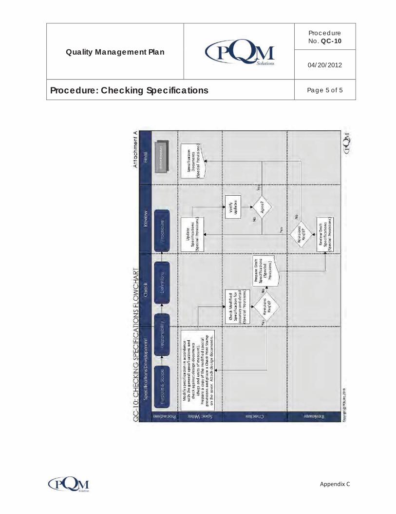
Quality Management Plan
Procedure No. QC-10
04/20/2012
Procedure: Checking Specifications Page 5 of 5
Appendix C

Quality Management Plan
Procedure No. QC-11
04/20/2012
Procedure: Design Review Program Page 1 of 15
Appendix C
1.0 Purpose and ScopeThe purpose of this procedure is to establish the sequence of activities and responsibilities that lead to a design submittal package. This procedure applies to all design packages that are submitted to the reviewing and approving agencies or organization.
Proper implementation of the Design Review Program will achieve consistency between design documents and ensure constructability. The reviews take place prior to each submittal during the design development process. Any variation among this process will require the approval of the Design Manager and Quality Manager. The Reviewers shall examine the documents for conflicts, interferences, consistency, completeness, and fullness between all disciplines of work.
2.0 Responsibility Design Managers or designee will facilitate the inter-discipline and constructability reviews.
Discipline Leaders or designee is responsible for the quality control within their discipline of work, conducting the discipline reviews, resolving comments and updating the design documents.
Quality Control Manager will coordinate the reviews. Frequently, the Design Managers also serves as the Quality Control Manager.
Design Reviewer shall have the technical expertise and qualifications to effectively perform the reviews and provide feedback that enhances the design.
Task Manager: Professional responsible for preparing the Submittal Package.
3.0 Definitions Accuracy Checks: The Quality Control Procedures are divided into three categories, project initiation, accuracy checks and design reviews. Accuracy checks include procedures of checking calculations, checking drawings, checking reports and checking specifications.
Checked Document: A version of the document (V0 or SxV0) that has completed the Accuracy Check.
Constructability: The effective and timely integration of construction knowledge, experience and lessons learned into planning and engineering design to contribute toward meeting the project objectives, costs and schedule.

Quality Management Plan
Procedure No. QC-11
04/20/2012
Procedure: Design Review Program Page 2 of 15
Appendix C
Constructability Review (CR): The use of construction and other specialized knowledge, experience and lessons learned in the review of construction documents to assist in coordinating planning, procurement and construction to achieve the overall project objectives.
Coordinated Documents (V2 or SxV2): Documents that have completed the Inter-Discipline Review and/or Constructability Review.
Design Review: A technical review of a version (Vx) or submittal package (SxVx).
Discipline Review (DR): A review of a single discipline of work. This review checks for completeness, consistency, methodology, standards and format in order to insure that all appropriate information (calculations, reports, drawings, estimates, specifications) is included with the discipline package. A discipline review shall also ensure that the proper accuracy check has been completed in accordance with the appropriate checking procedures.
Inter-Discipline Review (IDR): A review that is performed by two or more disciplines of work for coordination. The focus of the review is to identify design conflicts, and potential inconsistencies between disciplines of work. In addition, the work is reviewed for completeness, fullness, and proper fulfillment of standards..
Review Comments: As a result of a design review, the Reviewer will provide written comments of the technical review on a comment response log sheet that is provided to the designer.
Reviewed Documents (V1 or SxV1): Documents that have completed the Discipline Review.
Submitted Document (SxV3): The Submittal Package that was actually submitted for external review.
Submittal Package (Sx): A complete set of design documents required for the intended submittal. This may include calculations, drawings, reports, specifications, estimates, etc.
Version (Vx): A set of design documents that are either being checked or reviewed.
4.0 Process WorkflowThe Design Review Program starts after the Design Development Process is complete, including the accuracy checks. This is called Version 0 (V0) or the “Checked Documents”.

Quality Management Plan
Procedure No. QC-11
04/20/2012
Procedure: Design Review Program Page 3 of 15
Appendix C
It is acceptable for the accuracy checks, that are required during design development phase, and the Discipline Review be performed concurrently. The results of this scenario will lead directly to the production of Documents Version 1 (V1), or the Reviewed Documents.
Upon the completion of all the Discipline Reviews, the reviewed documents (V1’s) are combined into a multi-discipline review package. More than one set of completed V1 documents create a multi-discipline review package, and called a Submittal Package (SxV1).
The Submittal Package SxV1 advances to the Inter-Discipline & Constructability Review phase, and when the reviews are performed the Submittal Package Version 2 (SxV2) or the “Coordinated Documents” will be produced. Management Reviews will result with Submittal Package Version 3 (SxV3) being produced. After QA certification this package (SxV3) or the “Submitted Documents” will be ready for transmittal to the External Review.
The process describes the requirements to conduct the reviews and compile the three versions of the Submittal Package:
VO's V1: Discipline Review (DR) will be performed and result with Reviewed Document (V1’s) compiled into Submittal Package SxV1.
SxV2: Inter-Discipline (IDR) and Constructability Review (CR) will be performed and result with Coordinated Documents (V2’s) compiled into Submittal Package SxV2.
SxV3: Management Review (MR) and QA Certification will be completed and result with ready to submit documents (V3’s) compiled into Submittal Package (SxV3). Only V3 of the documents or Submittal Packages will be transmitted to the External Review (Agency) for review and approval.
The Design Review Program process workflow occurs in three phases, as shown in the following table and further illustrated in Attachment A: Design Review Program Process Flowchart.

Quality Management Plan
Procedure No. QC-11
04/20/2012
Procedure: Design Review Program Page 4 of 15
Appendix C

Quality Management Plan
Procedure No. QC-11
04/20/2012
Procedure: Design Review Program Page 5 of 15
Appendix C

Quality Management Plan
Procedure No. QC-11
04/20/2012
Procedure: Design Review Program Page 6 of 15
Appendix C
After the design review is completed, the Reviewer will prepare review comments on a Comment Response Log Sheet; the comments will be resolved; the design updated; accuracy checks conducted for the updated design; and the design is then advanced to the next version.
The color code system shown in the Design Protocol Procedure will be used for checking and reviewing each design version.
4.1 Discipline Review (V0 V1)The Discipline Review (DR) starts with reviewing the document version 0 (V0) and ends with document Version 1 (V1), which is called the “Reviewed Document”. It is acceptable for accuracy checks and the Discipline Review to be performed concurrently. The DR focuses on the

Quality Management Plan
Procedure No. QC-11
04/20/2012
Procedure: Design Review Program Page 7 of 15
Appendix C
review of a single discipline of work and starts after the design development and accuracy checks (V0) are complete such as; Checking Calculations, Checking Drawings, Checking Reports and Checking Specifications. The DR takes place prior to the Inter-Discipline and Constructability Review (IDR/CR).
The purpose of the DR is to confirm the consistency, reasonableness, completeness, assumptions, methodology, standards and presentation of a single discipline of work, to ensure that all appropriate information (calculations, reports, drawings, estimates, specifications) are included in the discipline package. The DR shall also ensure that all of the accuracy checks have been performed in accordance with the appropriate checking procedures.
The Reviewer’s comments will be evaluated, resolved and updated per the appropriate accuracy check procedures.
4.1.1 ResponsibilityThe Discipline Review is the responsibility of the Deliverable Discipline Leader.
4.1.2 Discipline Review Package PreparationThe Originator will prepare a complete review package including all of the design documents and supporting information. Place the Check Print stamp on each drawing, and sets of calculations; and place the Review Print stamp on the cover sheet of report, etc. It is acceptable to use an 8-1/2” x 11” sheet of paper (with the information on the Review Print stamp) stapled to the cover or top sheet of the review document in lieu of the inked review print stamp. Post the DR package on the document control system in the appropriate directory and folder, and notify the Reviewer.
4.1.3 Discipline ReviewThe Checker is responsible for the following activities:
a. The responsible Discipline Leader or designee will conduct the review for their discipline of work.
b. The design criteria and checklists for a specific discipline shall be used to complete the review for each discipline.
c. The Reviewers shall make their comments directly on the design documents provided and the comments shall be shown neat and legible.
d. Write name, discipline and date on check print stamp and review print stamp, as applicable.

Quality Management Plan
Procedure No. QC-11
04/20/2012
Procedure: Design Review Program Page 8 of 15
Appendix C
e. Return the review package with comments to the designer to evaluate the review comments and update the design accordingly.
4.1.4 Resolve CommentsThe Back Checker will evaluate the review comments and agree or disagree with the recommended comments. Any comments that the Back Checker disagrees with shall be resolved with the Reviewer(s).
a. Back Checker will discuss any disagreements with the Checker and resolve as appropriate. If agreement cannot be reached then the decision shall be elevated to the Discipline Leader who shall resolve the dispute and provide direction on how to proceed.
b. If the issue cannot be resolved with the Discipline Leader then it will be elevated to the Quality Control Manager who will identify a Subject Matter Expert to determine the resolution and provide direction on how to proceed.
c. Back Checker will write comment and resolution on the document. d. The appropriate corrections will be shown on the “Redlined” check set.
Meanwhile, the Designers may exercise the option to update the design document items that are in agreement.
4.1.5 Update DesignThe Updater is responsible for the updating the design in accordance with the appropriate accuracy check procedure:
QC-6: Checking Calculations QC-7: Checking Drawings QC-8: Checking Reports QC-9: Checking Specifications
The updated design will follow the process flow:
Check Back Check Update Verify
4.1.6 Completed Discipline Review The completed Discipline Review results in SxV1 or the Reviewed Document.
4.2 Inter-Discipline & Constructability Review (SxV1 SxV2)The Inter-Discipline (IDR) and Constructability Review (CR) start the review with SxV1 and ends with SxV2 or the “Coordinated Documents”. The IDR/CR may occur concurrently but both will

Quality Management Plan
Procedure No. QC-11
04/20/2012
Procedure: Design Review Program Page 9 of 15
Appendix C
follow the Discipline Review. The IDR/CR is performed by the Design Manager and the individual Discipline Leaders assigned by the Design Manager or Quality Control Manager.
The Discipline Leaders are primarily focused on the other discipline design documents rather than their individual discipline of work. The objective of the IDR is to identify conflicts, potential conflicts, inconsistencies between disciplines of work. However, any items that are found that will improve the design shall be noted as a comment.
The Design Manager’s review is focused on the completeness, thoroughness and fullness of the submittal package. The review shall also confirm that the submittal package content meets the scope of work and contract requirements. However, any items that are found that will improve the design shall be noted as a comment.
Constructability Reviews (CRs)
The Constructability Review shall be performed when required by the Design Manager. The CR’s primary focus is to confirm the buildability of the design, contractor equipment and resource mobility, potential conflicts and staging of the construction; efficient construction method and how various construction methods will be applied to build a work item or series of work items; identifying efficiencies or inefficiencies that can be improved with a different design approach; identify safety concerns and determine how they can be eliminated. However, any items that are found that will improve the design shall be noted as a comment.
4.2.1 ResponsibilityThe individual Discipline Leaders are responsible for the inter-discipline reviews.
4.2.2 Inter-Discipline Review Package PreparationThe Inter-Discipline Review Package will include the following items for the reviewers and shall be delivered as follow:
a. All design documents required for the submittal.
b. The applicable discipline design criteria and review checklists.
c. Post the Submittal Package on the document control system in the appropriate directory for the SxV1 review.
d. Notify the reviewers that the Review Package has been posted to the document control system and provide the electronic link to the files.

Quality Management Plan
Procedure No. QC-11
04/20/2012
Procedure: Design Review Program Page 10 of 15
Appendix C
4.2.3 Inter-Discipline Review Procedure The format of the IDR takes place as a one or two step process. First an individual IDR is performed, followed by an optional IDR workshop. Using both, an individual and workshop IDR approach, is very effective and encouraged, when practical. However, if the individual IDR’s are not completed by all of the IDR Reviewers prior to the IDR Workshop, the Workshop may get bogged down with checking and require a longer review schedule. For best results, the IDR will combine the individual IDR followed by the IDR workshop and allow sufficient time to accomplish the reviews.
a. A schedule for the review will be established by the Quality Control Manager or designee and based on the size and complexity of the design package.
b. The Reviewer shall use the color code system and mark directly on the design documents being reviewed.
c. Comments shall be shown neat and legible. d. Each Reviewer will make their comments on a Comment Response Log Sheet Form. A
scanned copy of the review print markups can be attached to the Comment Form. e. The reviewer will placed Comment Response Log Sheet Form in document control
system, as scheduled.
4.2.4 Resolve CommentsBack Checker The Back Checker will evaluate the review comments and agree or disagree with the recommended comments. Any comments that the Back Checker disagrees with shall be resolved with the Reviewer(s).
a. Back Checker will discuss any disagreements with the Checker and resolve as appropriate. If agreement cannot be reached then the decision shall be elevated to the Discipline Leader who shall resolve the dispute and provide direction on how to proceed.
b. If the issue cannot be resolved with the Discipline Leader then it will be elevated to the Quality Control Manager who will identify a Subject Matter Expert to determine the resolution and provide direction on how to proceed.
c. Back Checker will write comment and resolution on the document. d. The appropriate corrections will be shown on the “Redlined” check set.

Quality Management Plan
Procedure No. QC-11
04/20/2012
Procedure: Design Review Program Page 11 of 15
Appendix C
Meanwhile, the Designers may exercise the option to update the design document items that are in agreement.
4.2.5 Update DesignThe design will be updated in accordance with the appropriate accuracy check procedure:
QC-6: Checking Calculations QC-7: Checking Drawings QC-8: Checking Reports QC-9: Checking Specifications
The updated design will follow the process flow:
Check Back Check Update Verify
4.2.6 Completed IDR/CRThe completed IDR and CR results in SxV2
4.3 Management Review (SxV2 SxV3)The Management Review (MR) starts with the review of SxV2 and ends with SxV3. The primary focus of the MR is to confirm that the Submittal Package is complete and meets the scope of work, contract requirements and the quality expectations of the Design Manager.
4.3.1 ResponsibilityThe Task Manager is responsible for the Management Review.
4.3.2 Management Review Package Preparation (SxV2)The Management Review Package will include the following items for the reviewers and shall be delivered as follow:
a. All design documents required for the Submittal Package.
b. The applicable discipline design criteria and review checklists.
c. Post the Submittal Package on the document control system in the appropriate directory for the SxV2 review.
d. Notify the Design Manager, Quality Manager and Project Manager that the SxV2 Review Package has been posted document control system and provide the electronic link to the files.

Quality Management Plan
Procedure No. QC-11
04/20/2012
Procedure: Design Review Program Page 12 of 15
Appendix C
4.3.3 Management Review ProcedureGenerally, after the rigorous reviews the Submittal Package has gone through, there are only minor items that will be found and need to be corrected. Regardless of the magnitude of the revisions the corrections continue to follow the process described in the DR and IDR/CR.
a. A schedule for the review will be established by the Design Manager or designee and based on the size and complexity of the design package.
b. The Reviewer shall use the color code system and mark directly on the design documents being reviewed.
c. Comments shall be shown neat and legible. d. The Reviewer(s) will make their comments on a Comment Response Log Sheet Form. A
scanned copy of the review print markups can be attached to the Comment Form. e. The reviewer will placed Comment Response Log Sheet Form in document control
system, as scheduled.
4.3.4 Resolve CommentsBack Checker The Back Checker will evaluate the review comments and agree or disagree with the recommended comments. Any comments that the Back Checker disagrees with shall be resolved with the Reviewer(s).
a. Back Checker will discuss any disagreements with the Checker and resolve as appropriate. If agreement cannot be reached then the decision shall be elevated to the Discipline Leader who shall resolve the dispute and provide direction on how to proceed.
b. If the issue cannot be resolved with the Discipline Leader then it will be elevated to the Quality Control Manager who will identify a Subject Matter Expert to determine the resolution and provide direction on how to proceed.
c. Back Checker will write comment and resolution on the document. d. The appropriate corrections will be shown on the “Redlined” check set.
Meanwhile, the Designers may exercise the option to update the design document items that are in agreement.
4.3.5 Update DesignThe design will be updated in accordance with the appropriate accuracy check procedure:
QC-6: Checking Calculations QC-7: Checking Drawings
Quality Management Plan
Procedure No. QC-11
04/20/2012
Procedure: Design Review Program Page 13 of 15
Appendix C
QC-8: Checking Reports QC-9: Checking Specifications
The updated design will follow the process: Check Back Check Update Verify
4.3.6 Completed Management Review (MR)The completed MR results in SxV2, ready for submittal to External Review.
5.0 Document ControlA copy of the design review comments are quality records. The Deliverable Discipline Leader will maintain a hardcopy of the quality records until the Quality Assurance Manager has signed the Quality Assurance Certification Statement for the specific submittal package. An electronic copy of the review documents shall be stored as directed by the Document Control procedure.
6.0 ReferencesQC-6: Checking Calculations QC-7: Checking Drawings QC-8: Checking Reports QC-9: Checking Specifications
7.0 Attachments8.0 Attachment A: Design Review Program Flowchart

Quality Management Plan
Procedure No. QC-11
04/20/2012
Procedure: Design Review Program Page 14 of 15
Appendix C

Quality Management Plan
Procedure No. QC-11
04/20/2012
Procedure: Design Review Program Page 15 of 15
Appendix C

Quality Management Plan
Procedure No. QA-1
04/20/2012
Procedure: Quality Assurance Program Page 1 of 6
Appendix C
1.0 Purpose and ScopeThe Quality Assurance Program procedure defines the process used for the project to assure that the engineering and design activities are accomplished in accordance with the DQMP. Adherence to the DQMP is required by all designers performing work on the project.
2.0 Responsibility Design Quality Manager
3.0 Definitions Acceptance Criteria: Specified limits placed on characteristics of an item, process or service defined in planning and design manuals, standards, or other required documents.
Audit: A systematic, independent and documented activity performed in accordance with written procedures or checklists to verify, by examination and evaluation of objective evidence, that applicable elements of the quality control and quality assurance program have been developed, documented, and effectively implemented in accordance with specific requirements.
Corrective Action: A change implemented to address an identified weakness in the management system or correct a nonconforming condition.
Design: The design refers to any calculation, analysis, drawing, report and scientific evaluations that influence the end product. The end products are the documents that clear a project for construction.
Design Quality Assurance Records: Design quality assurance records are the quality assurance forms and reports prepared as part of the work activity directed by the quality assurance procedures.
Design Quality Management Plan (DQMP): An element of the overall project quality management system that address intended quality control and quality assurance processes to be implemented with the design activities.
External Audit: An audit of those portions of another organization’s quality assurance/quality control plan not under the direct control or within the organizational structure of the auditing organization.
Nonconforming Condition: A deficiency in characteristic, documentation, or procedure, which renders the quality of an item unacceptable or indeterminate by failing to meet requirements.

Quality Management Plan
Procedure No. QA-1
04/20/2012
Procedure: Quality Assurance Program Page 2 of 6
Appendix C
Examples include physical defects, test failures, incorrect or inadequate documentation or deviation from prescribed design processes, inspection or test procedures
Quality Assurance: The total effort of development, documentation, implementation of policies, definition of roles and responsibilities and procedures to achieve and verify quality in accordance with specified requirements.
Quality Control: The acts of examining, witnessing, inspecting, checking, and when necessary, revision, of in-process or completed work, for both design and construction, to determine conformity with contract requirements.
Review: The process of examining, commenting on and evaluating procedures, processes, drawings, specifications and related data to determine that they clearly, accurately and completely describe the design and quality requirements.
Surveillance: Monitoring, witnessing or observing to verify whether or not an item or activity conforms to specified requirements.
Verification: The act of reviewing, inspecting, observing, checking, auditing or otherwise determining and documenting whether items, processes, services or documents conform to specified requirements.
4.0 ProcedureQuality Program Implementation
A successful program requires the initial implementation of the system and procedures and surveillance, monitoring and audits to achieve the desired quality of products and services.
The personnel assigned to perform the work need to understand and accept their roles and responsibilities to achieve success. The Design Manager must endorse the program and encourage other managers and leaders to engage the requirements and engage their subordinate staff. The QA Manager reports to the Project Manager and is responsible for developing and maintaining the Design Quality Management Plan (DQMP), supporting the Project Manager and Design Manager, and evaluating the effectiveness of the program. In addition the QA Manager is responsible for:
Implementing an audit and surveillance plan to monitor project activities and determine compliance with the DQMP requirements.

Quality Management Plan
Procedure No. QA-1
04/20/2012
Procedure: Quality Assurance Program Page 3 of 6
Appendix C
Routinely report to management on quality assurance/quality control activities and issues of concern.
Review and approve subconsultant and vendor DQMP, if applicable.
Attend project meetings to address quality agenda items, as necessary.
Identify corrective action and initiate, recommend, coordinate and provide solutions for quality problems.
Provide quality assurance indoctrination and training to project personnel.
Surveillance and Monitoring
Surveillance and monitoring activities will be coordinated with Design Manager and incorporated into the project schedule with minimal impact on the normal conduct of project work. There are scheduled and unscheduled monitoring activities. Scheduled activities are included in the quality assurance planning process and coordinated with the Design Manager and project controls. Evidence of compliance with specific quality program requirements is examined during surveillance and monitoring activities. Surveillance and monitoring activities may include evidence that the DQMP is properly implemented. Surveillance and monitoring activities are reported monthly in a quality assurance activity report that will include: comment resolution, non-conformance, corrective action requests and resolution and program discrepancies.
Quality Audits
Quality audits can be internal or external. Internal quality program audits shall be conducted in accordance with quality assurance audit procedure and external quality program audits of design consultants shall be conducted in accordance with quality assurance audits of contractor procedures.
Quality audits are conducted to verify conformance with approved policies and procedures. Audits will be conducted on schedule commensurate with the activities being performed. The audit frequency may vary depending on the nature, risks and importance of the activities being performed and the results achieved. Audits shall be performed using checklists developed from applicable project procedures and technical requirements of engineering drawings, design output and quality assurance/quality control plan procedures. Departure or failure to implement the requirements of the governing documents shall be recorded as an audit finding.

Quality Management Plan
Procedure No. QA-1
04/20/2012
Procedure: Quality Assurance Program Page 4 of 6
Appendix C
Audit performance shall be documented by an audit report which at a minimum shall include the following information:
A narrative summary of the scope of the audit for each area audited.
Identification of the auditor and persons contacted during the audit.
Summary of audit results and a determination of the program effectiveness.
Clearly defined audit findings.
Corrective action request and completion date.
Audit results shall be reported to the Design Manager and Project Manager of the project. The project shall take timely and appropriate action to correct conditions documented by the audit findings and to prevent recurrence. Implementation of corrective action for deficient areas shall be verified by QA follow-up action, such as reviews of documentation and activities or re-audits, as necessary.
Numbering Convention
Observations, surveillances, audits and corrective action reports will be numbered using a convention to easily relate and link these reports to the appropriate activity. Each report and form has a location for the record number (CAR#, AO#, etc.). The report activity will be tracked using a log sheets by date and number and will accompany the monthly report.
Design Quality Assurance Reports
Quality assurance reports shall be prepared monthly and maintained with the project quality assurance records.

Quality Management Plan
Procedure No. QA-1
04/20/2012
Procedure: Quality Assurance Program Page 5 of 6
Appendix C
Procedure Old Rev Rev Date Title Revision Description New Rev
Revision Date
QA-1 0 November 11, 2010 Quality Assurance Program
QA-2 0 November 11, 2010 Quality Assurance Planning
QA-3 0 November 11, 2010 Design Surveillance
QA-4 0 November 11, 2010 Design Quality Assurance Audits
QA-5 0 November 11, 2010 Quality Review
QA-6 0 November 11, 2010 Quality Assurance Records
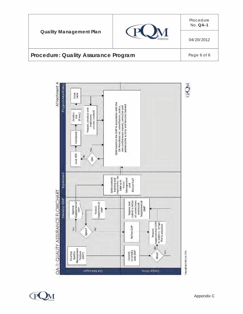
Quality Management Plan
Procedure No. QA-1
04/20/2012
Procedure: Quality Assurance Program Page 6 of 6
Appendix C

Quality Management System 07/24/13 – Rev. 1.0
Appendix D
Contents:
Quality Control Checklists

The Port of Long Beach Quality Management System
QUALITY CONTROL CHECKLISTS
PROGRAM MANAGEMENT DIVISION
File Name: QC Checklists Version Number: Rev 1.0 Version Date: 07/24/2013

Quality Control Review Checklists
Quality Management System 07/24//2013 Rev. 1.0 Appendix D 1
Table of Contents Discipline: SURVEYS .......................................................................................................................................................................... 2
Discipline: GEOTECHNICAL ............................................................................................................................................................... 3
Discipline: ENVIRONMENTAL ............................................................................................................................................................ 4
Discipline: EXTERNAL CUSTOMERS ................................................................................................................................................ 5
Discipline: Safety – Traffic Studies ...................................................................................................................................................... 6
Discipline: SITE DESIGN .................................................................................................................................................................... 7
Discipline: HYDROLOGY .................................................................................................................................................................... 9
Discipline: HYDRAULICS .................................................................................................................................................................. 10
Discipline: TRAFFIC .......................................................................................................................................................................... 11
Discipline: TRAFFIC DESIGN ........................................................................................................................................................... 12
Discipline: MARINE/WHARF ............................................................................................................................................................. 13
Discipline: ELECTRICAL DESIGN .................................................................................................................................................... 14
Discipline: ELECTRICAL DESIGN .................................................................................................................................................... 15
Discipline: HAZARDOUS WASTE ..................................................................................................................................................... 18
Discipline: MATERIALS ..................................................................................................................................................................... 19
Discipline: LANDSCAPE ................................................................................................................................................................... 20
Discipline: WATER POLLUTION ....................................................................................................................................................... 21
Discipline: WATER POLLUTION-Design Phase ............................................................................................................................... 22
Discipline: ARCHITECTURE / BUILDING ......................................................................................................................................... 23
Discipline: SECURITY ....................................................................................................................................................................... 24
Discipline: COMMUNICATIONS ....................................................................................................................................................... 25
Discipline: SPECIFICATIONS ........................................................................................................................................................... 26
Discipline: CONSTRUCTION ............................................................................................................................................................ 27
Discipline: BID COMPLIANCE .......................................................................................................................................................... 28
Discipline: MAINTENANCE ............................................................................................................................................................... 29
Discipline: (_______________) ......................................................................................................................................................... 31
GLOSSARY ...................................................................................................................................................................................... 33
REVIEW STEPS ............................................................................................................................................................................... 33
REVIEW STEPS ............................................................................................................................................................................... 34
PROJECT REVIEW STEPS .............................................................................................................................................................. 35

Quality Control Review Checklists
Quality Management System 07/24//2013 Rev. 1.0 Appendix D 2
Discipline: SURVEYS
Project Name: Checked By: Date: BackChecked By: Date: Milestone
I. Key Constructibility Issues Pre-
Design 15% 50% 100% Final
1. Horizontal control Information: ie; NAD 27 or NAD 83 monuments used for control, Calif. Coord. System
2. Vertical control: Datum used and benches for vertical control 3. Bearings, stationing, curve information (alignment) 4. All dimensions 5. Drainage plans and profiles 6. Determine that the plans are stakeable from a construction survey point of view 7. Right-of-way summary traverses 8. Sub grade & finished grade slope stake listings 9. Cross sections – w/finished and subgrade 10. Previous suggestions/corrections addressed
Place initial in column to ensure each item is included & reviewed. Place NA if not applicable.
The checker and backchecker shall sign and date for current milestone checked.

Quality Control Review Checklists
Quality Management System 07/24//2013 Rev. 1.0 Appendix D 3
Discipline: GEOTECHNICAL
Project Name: Checked By: Date: BackChecked By: Date:
Milestone
I. Key Constructibility Issues Pre- Design
15% 50% 100% Final
II. Key Maintainability Issues III. Key Safety Issues
Place initial in column to ensure each item is included & reviewed. Place NA if not applicable.
The checker and backchecker shall sign and date for current milestone checked.

Quality Control Review Checklists
Quality Management System 07/24//2013 Rev. 1.0 Appendix D 4
Discipline: ENVIRONMENTAL
Project Name: Checked By: Date: BackChecked By: Date:
Key Environmental Issues (Planners should initial Satisfactory/Unsatisfactory column as appropriate to
comments)
Satisfactory Unsatisfactory Comments
Preliminary Engineering
1. Complete Environmental Document Assessment worksheet submitted to Environmental Planning
2. Project Description complete and unchanged 3. Alternatives identified and adequate/Consideration for each alternative 4. Environmental Status estimate section included
5. Environmental Permit estimate: 404/401/1601/NPDES/SWPPP included
6. All areas of possible impacts (CEQA +/or NEPA) identified
7. Determination of Water Pollution Control elements/Scope (NPDES) as SWPPP or WPCP included in the Permits section
8. Environmental Scoping Checklist for Project Reports included, if required
9. Adequate format, spelling and grammar
Preliminary Engineering Design Report
1. Adequate project description
2. Confirm type of ED required / Federal involvement
3. NEPA / 404 process identified, if applicable
4. Construction / Post Construction Impacts reviewed
5. Mitigation Monitoring Plan Prepared
6. Mitigation Compliance Cost Estimate (MCCE) Form completed
7. Obtain Resource Agency Permit determination from Bio Pool
8. NEPA concurrence from FHWA (if required)
9. Report Resource Agency permit costs to ROW prior to Project Report Cost Estimates
10. Final Environmental Document completed with all required signatures
Project Specifications & Estimate (PS&E)
1. All permit requirements determined and permit requests issued 18 months prior to construction start date
2. Is environmental reevaluation required due to possible project changes?
3. Environmentally Sensitive Areas included on Design Plans, if needed
4. All permit requirements identified, Specs for Bio permits included with impacts of Construction windows identified
5. All mitigation measures required in the ED Addressed, Mitigation Monitoring program established.
6. Water Pollution control / NPDES review conducted at 15, 50, 100%. Current NPDES permits and correct Water Pollution Control time Periods included
7. Determination of possible groundwater pumping; notice of this activity and required testing and reporting included in Special Provisions.
Place initial in column to ensure each item is included & reviewed. Place NA if not applicable.
The checker and backchecker shall sign and date for current milestone checked.

Quality Control Review Checklists
Quality Management System 07/24//2013 Rev. 1.0 Appendix D 5
Discipline: EXTERNAL CUSTOMERS
Project Name: Checked By: Date: BackChecked By: Date: Milestone
I. OTHER PROJECT SPECIFIC ISSUES
Fill in any External Customer Requirements on this summary sheet. Signature at the bottom of this sheet requires that this checklist has been completed.
Pre- Design
15% 50% 100% Final
1. Public Information: Investigate existing community concerns; identify possible issues, which require early dialogue.
2. Determine the need for Visual Impact Assessment-Environmental Document
I certify that the Project Review Team has reviewed the above items. Project Review Team Representative: __________________________________________________ Project Manager: __________________________________________________

Quality Control Review Checklists
Quality Management System 07/24//2013 Rev. 1.0 Appendix D 6
Discipline: Safety – Traffic Studies
Project Name: Checked By: Date: BackChecked By: Date:
Milestone
I. KEY SAFETY ISSUES
Pre- Design
15% 50% 100% Final
1. Adherence to concept, scope and budget 2. Accident Data, rates, analysis, characteristics 3. Traffic Volume, i.e., truck %, directional split, %ADT, peak hour volume 4. Overall Design Relative to Safety and Operations 5. Traffic Safety Systems, i.e., MBGR, barriers, attenuators, length of need 6. Signs, correct message, design, placement 7. Pavement markings, striping 8. Lane and shoulder widths 9. Overall review of Clear Recovery Zone within the roadside environment 10. Comment of submitted signal warrants, LOS, intersection capacity, and highway
segment capacity
11. Does project have adequate Safety Lighting
12. Utilize Outer Separation Wall where required 13. Place Cable Railing where required
14. Does signing package prevent Wrong Way moves
15. Geometrics – Use of optimum standards, not minimum standards
Place initial in column to ensure each item is included & reviewed. Place NA if not applicable.
The checker and backchecker shall sign and date for current milestone checked.

Quality Control Review Checklists
Quality Management System 07/24//2013 Rev. 1.0 Appendix D 7
Discipline: SITE DESIGN
Project Name: Checked By: Date: BackChecked By: Date:
Milestone
I. KEY CONSTRUCTABILITY ISSUES Pre-
Design 15% 50% 100% Final
1. Traffic Management Plan(vehicular and rail) has been developed, if required 2. Preliminary structures studies performed
a. Location 1 b. Location 2 c. Location 3
3. Preliminary materials investigation conducted 4. Drainage mitigation measures proposed 5. Development of workable construction staging plans complete and shown on plans 6. Specifications for traffic handling are included 7. Conflicts with on-going projects identified 8. Construction easements adequate 9. Identification and avoidance of section 4(f) properties 10. All necessary permits to construct identified/acquired 11. Adequate access for residents & businesses in areas under construction 12. Necessary construction details covered in project plans 13. Work shown on plans is adequately described in Specs 14. Utility plans conform to Port's and City policies for high & low risk facilities 15. Hazardous Waste sites identified and mitigation plan developed 16. Proposed “work-arounds”, if needed, are clearly defined 17. Drainage interface with adjoining projects 18. The specifications should clarify and differentiate the payment for raising/lowering
between water valve and manhole cover. Specifications should cover disposition of all utilities such as fuel, oil and gas.
19. Consistency between roadway, rail tracks and structure plans 20. Materials Report recommendations for:
a. Embankment foundations and settlement estimates b. Slope Design c. Subsurface/groundwater control d. Tidal impacts, erosion and corrosion
21. Railroad involvement identified 22. Impacts of construction windows required by environmental Resource Agencies 23. What about SWPPP issues 24. Previous suggestions/corrections addressed 25. Conduct a field review with maintenance & construction personnel 26. List the existing and proposed road and lane
widths_____________________________
27. List the existing and proposed shoulder widths____________________________ 28. List any non-standard design features______________________________________ 29. Construction staging covered in sign plan 30. Staging plans show how traffic is being handled for each traffic stage shows
striping/marker plan and shooflies
II. KEY SAFETY ISSUES 1. Are Clearance Requirements met? 2. Are Design Standards Met? 3. Provide Standard roadway Widths at all locations 4. Provide Proper Sight Distances 5. Provide Horizontal Curve Sight Distance Set Backs and Clear Areas when designing
Landscape Planting and Irrigation Systems.
6. Ensure that the Grading on Loop Ramps does not impair Sight Distance

Quality Control Review Checklists
Quality Management System 07/24//2013 Rev. 1.0 Appendix D 8
7. The Maximum of 2:1Slopes should not be exceeded when landscape planting is required.
8. Remove or protect roadside fixed objects 9. Does driveways or entrances prevent wrong way moves. 10. Where practical, signing and lighting facilities should be located adjacent to outside
shoulders not in the median.
11. Traffic Control Boxes should be located as far away from the edge of roadway as practical or be placed behind an existing concrete wall
12. Place Cable Railing on Retaining Walls where required. 13. Does this project provide adequate access for: A: Vehicle access gates and access roads
B. Personnel access gates C: Access to drainage facilities D: Access to Retaining Walls
E. Provide maintenance vehicle access F. Access to electrical, irrigation, signs
14. List below any other safety considerations not previously identified. 15. Insure proper pavement markings and adequate pavement delineation. 16. Insure proper concrete barrier placement with correct treatments 17. Use proper advisory speed for curves 18. Use proper Superelevation and location of “sag point” to prevent drainage problems 19. Insure the placement of safety shapes where req’d at retaining walls and bridge railing 20. Conforms to Design for Safety Guidelines
Place initial in column to ensure each item is included & reviewed. Place NA if not applicable.
The checker and backchecker shall sign and date for current milestone checked.

Quality Control Review Checklists
Quality Management System 07/24//2013 Rev. 1.0 Appendix D 9
Discipline: HYDROLOGY
Project Name: Checked By: Date: BackChecked By: Date:
Milestone
I. Key Constructibility Issues Pre-
Design 15% 50% 100% Final
1. Ultimate drainage basin design protects private property and freeway against flooding 2. Minimum diversion of natural stream flow 3. SAG points of depressed sections of alignment designed for 50-year storm 4. Pumping plants designed according to Pumping Plant Design Manual 5. Upstream and downstream effect on run-off is addressed 6. Are water quality (surface groundwater) impacts anticipated and mitigated (detention and/or retention ponds required) & BMPs
7. Are dewatering systems needed 8. Previous suggestions/corrections addressed
Place initial in column to ensure each item is included & reviewed. Place NA if not applicable.
The checker and backchecker shall sign and date for current milestone checked.

Quality Control Review Checklists
Quality Management System 07/24//2013 Rev. 1.0 Appendix D 10
Discipline: HYDRAULICS
Project Name: Checked By: Date: BackChecked By: Date:
Milestone
I. Key Constructibility Issues Pre-
Design 15% 50% 100% Final
1. Approved preliminary drainage report 2. Approved vertical and horizontal alignment 3. Typical cross-section 4. Preliminary drainage plans 5. Maintainable facility with sufficient right-of-way and/or drainage easements 6. Utilization of correct erosion factors for slope soil loss, stream aggravation/degradation
outlet velocities
7. Subsurface conditions studied adequately including groundwater control 8. Flow diversion/connection approved by appropriate agencies 9. Drainage for construction staging 10. All drainage DI’s & drainage facilities surveyed 11. Determine utility location (potholing) and utility survey 12. Detention & sedimentation ponds 13. Drainage interface with adjoining projects or future projects 14. Drainage plans, profiles and details are sufficient including special designs for large
underground structures
15. Grading plans 16. Noise barrier and/or retaining wall drainage plans adequate 17. Bridge and/or pumping plant plans included 18. Erosion Control plans complete and sufficient to be coordinated with Landscape
Architects.
19. Pipe jacking method appropriate for given site conditions 20. Materials report recommendations for back-filling adequate 21. Channel lining adequate for conditions and availability of source 22. Drainage is consistent with roadway and structure plans 23. Drainage quantity estimates accurate 24. Drainage specifications adequate 25. All required permits obtained including cooperative agreements 26. Floodplain issues resolved (ie, impact on base flood elevation) 27. Computability of project with future projects
II. Key Maintainability Issues
1. Provide Access to Drainage, Controllers (Irrigation and Electrical) and Pump Stations 2. Provide Maintenance Pullouts at Pump Houses 3. Do not use Sole Source Materials 4. No Composite Material Lids for Vaults on Pavement III. Key Safety Issues 1. Does this project provide adequate access for Access to drainage facilities
Place initial in column to ensure each item is included & reviewed. Place NA if not applicable.
The checker and backchecker shall sign and date for current milestone checked.

Quality Control Review Checklists
Quality Management System 07/24//2013 Rev. 1.0 Appendix D 11
Discipline: TRAFFIC
Project Name: Checked By: Date: BackChecked By: Date:
Milestone
I. Key Constructibility Issues Pre- Design
15% 50% 100% Final
Traffic Management Plan has been developed, if required Development of workable construction staging plans/detour routes completed Stage construction is adequately shown on plans Specifications for traffic handling & lane closures are included Adequate access for residents & businesses in areas under construction Signing and pavement delineation plans Construction area signs
II. Key Maintainability Issues
Use Thermoplastic Material for permanent pavement markings Provide Maintenance areas at:
Overhead Signs, Changeable Message Signs and CCTV Poles Traffic Controllers Cabinets Do not use Sole Source Materials Avoid Signs in the median III. Key Safety Issues 1. Where practical, signing and lighting facilities should be located adjacent to outside
shoulders not in median
2. Traffic Control Boxes should be located as far away from the edge of shoulder as practical or be placed behind an existing concrete wall, MBGR or bridge abutment.
3. Are Signs placed at correct locations to direct motorists safely? 4. List below any other safety considerations not previously identified. 5. Insure proper pavement markings 6. Use proper advisory speed signs for curves. 7. When signal involved need to check existing lenses & prepare traffic signal warrant
Place initial in column to ensure each item is included & reviewed. Place NA if not applicable.
The checker and backchecker shall sign and date for current milestone checked.
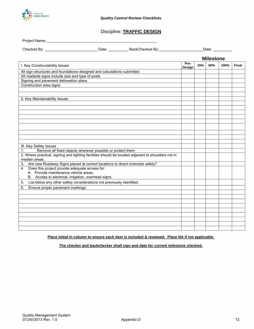
Quality Control Review Checklists
Quality Management System 07/24//2013 Rev. 1.0 Appendix D 12
Discipline: TRAFFIC DESIGN Project Name: Checked By: Date: BackChecked By: Date: Milestone
I. Key Constructability Issues Pre- Design
15% 50% 100% Final
All sign structures and foundations designed and calculations submitted All roadside signs include size and type of posts Signing and pavement delineation plans Construction area signs
II. Key Maintainability Issues
III. Key Safety Issues 1. Remove all fixed objects wherever possible or protect them 2. Where practical, signing and lighting facilities should be located adjacent to shoulders not in median areas.
3. Are new Roadway Signs placed at correct locations to direct motorists safely? 4. Does this project provide adequate access for:
A. Provide maintenance vehicle areas. B. Access to electrical, irrigation, overhead signs.
5. List below any other safety considerations not previously identified. 6. Ensure proper pavement markings
Place initial in column to ensure each item is included & reviewed. Place NA if not applicable.
The checker and backchecker shall sign and date for current milestone checked.

Quality Control Review Checklists
Quality Management System 07/24//2013 Rev. 1.0 Appendix D 13
Discipline: MARINE/WHARF
Project Name: Checked By: Date: BackChecked By: Date:
Milestone
I. Key Constructibility Issues Pre- Design
15% 50% 100% Final
Follow the POLB Wharf Design Criteria (Version 3.0) Construction Equipment access Prevention of water pollution Geotechnical consideration Structural Load Criteria Seismic Design Criteria Structural Consideration Electrical Considerations
II. Key Maintainability Issues III. Key Safety Issues
Place initial in column to ensure each item is included & reviewed. Place NA if not applicable.
The checker and backchecker shall sign and date for current milestone checked.

Quality Control Review Checklists
Quality Management System 07/24//2013 Rev. 1.0 Appendix D 14
Discipline: ELECTRICAL DESIGN
Project Name: Checked By: Date: BackChecked By: Date: Milestone
Place initial in column to ensure each item is included & reviewed. Place NA if not applicable.
The checker and backchecker shall sign and date for current milestone checked.
I. Key Constructibility Issues Pre- Design
15% 50% 100% Final
Power source identified for permanent & temporary electrical systems II. Key Maintainability Issues
Provide maintenance Pullouts including Controllers and Valves, Backflow Preventors and Booster Pump Locations
Do not use Sole Source Materials Provide Protective Devices Around Electrical Control Cabinets Have all electrical wiring placed in conduit and color code all wiring for maintenance. III. Key Safety Issues Where practical, signing and lighting facilities should be located adjacent to shoulders Does this project provide adequate access for: Maintenance vehicle Access to electrical, irrigation, overhead signs & CMS Boards

Quality Control Review Checklists
Quality Management System 07/24//2013 Rev. 1.0 Appendix D 15
Discipline: ELECTRICAL DESIGN
Project Name: Checked By: Date: BackChecked By: Date: Milestone
I. Key Constructibility Issues Pre- Design
15% 50% 100% Final
Standard sheet title is used. All electrical plans shall be labeled the title of each electrical plan shall be the bid item, a portion of the bid item or combination of bid items
Standard Note is placed on the electrical plans.
Show north arrows Show street name and freeway. Show Registration Seal Use Standard symbols and notes for electrical equipment whenever possible. Show service points. All service point for power and telephone shall be confirmed with the serving utilities companies during design stage
Show voltage, number and rating of circuit breakers Use 200 scale plan for signal plans and 500 scale plan for others. Conduit runs between signal pole & nearest pull box do not need to be called out. Provide at least 2 – 78 mm conduit from controller cabinet to the nearest #6 pull box. Use 26% conduit fill for new conduit, 35% conduit fill for existing conduit.
SIGNAL AND LIGHTING
Need warrant for new signal installation.
Show lane striping.
Remove existing signal pole foundation complete if removing signal pole.
Show separate signal removal plan if all the signal poles are removed. Show existing phase diagram and existing pole and equipment schedule.
Label loop detectors with input file names.
Use 12-conductor signal cable (12 CSC) for signal conductor. Use 3 CSC for pedestrian push buttons Conductor signal cable shall be uncut/unspliced between the controller and the signal pole terminal box. Each 12 CSC will service one even phase, one odd phase and one pedestrian signal phase.

Quality Control Review Checklists
Quality Management System 07/24//2013 Rev. 1.0 Appendix D 16
ELECTRICAL QC CHECKLIST (PAGE 2 OF 3)
Milestone
Technical Review Items Pre-
Design 15% 50% 100% Final
Signal interconnect cable shall be 12 pair #19 AWG copper. Interconnect cable cannot be spliced, except in approved splice cabinets, and shall be run continuous from one controller location to another.
On roadway luminaires: Use 200-watt HPS lamps for 9.1 m mounting height and 310 watt HPS for 10.7 m mounting height.
Designer shall verify the minimum horizontal illuminance as follow: 1.6 horizontal lux on the area normally bounded by the crosswalks and 6.5 horizontal lux at the intersection of centerline of the entering streets. A light depreciation factor must be applied to determine the maintained level of lighting since the isolux diagrams are based on initial values.
Show proposed phase diagram, conductor and conduit schedule, and pole and equipment schedule.
Safety lighting at an intersection is unmetered. Ballast for luminaire shall be the lag regulator type. Safety lighting and llSNS conductors at a signalized intersection should not enter the model 170-controller cabinet.
LIGHTING AND SIGN ILLUMINATION
Only one set of notes is shown on the first sheet of lighting and sign illumination. Provide wiring diagram and legend for lighting and sign illumination. Do not use mercury contractor, use mechanical contractor only. Numbers of sign fixtures conform to Standard Plans. All lighting standards to be removed and relocated are to be identified by Type Provide separate lighting removal plans except for minor lighting upgrades or modifications. Conduit sizes, number and sizes of conductors are shown on the plans. Ballast for luminaire shall be the lag regulator type.

Quality Control Review Checklists
Quality Management System 07/24//2013 Rev. 1.0 Appendix D 17
ELECTRICAL QC CHECKLIST (PAGE 3 OF 3) Milestone
TECHNICAL REVIEW ITEMS Pre- Design
15% 50% 100% Final
CLOSED CIRCUIT TELEVISION SYSTEM
1. Type 334-TV cabinet for CCTV shall be contractor-furnished. 2. Provide camera details. 3. Conductor and conduit schedule is shown on the plans.
CHANGEABLE MESSAGE SIGN SYSTEM
1. Provide circuit breakers detail. 2. Conductor and conduit schedule is shown on the plans. 3. CMS signal and current sense cables are state-furnished materials.
COMMUNICATION SYSTEM
1. Only one set of notes is shown on the first sheet of communication system plan. 2. All legend and abbreviations not defined in the Standard plans are shown on the first sheet. 3. Standard fiber optic cables are used. 4. Conductor and conduit schedule is shown on the plans. 5. Provide conduit trench and jacking details. 6. Provide details for communication pull box and splice vault. 7. Provide conduit bridge attachment details if applicable. 8. Provide communication system overall diagram. 9. Provide field elements schematic details. 10. Provide data node, video node, and cable node details. 11. Provide fiber assignment tables. 12. Provide TDM channel assignment details. 13. Provide video mux channel assignment. 14. Provide interface to existing traffic element details. 15. Provide interface to existing CCTV details. 16. Provide Hub or TMC details. 17. Provide fiber optic splicing details.
Specifications
1. Provide specifications for all items included in the contract plans. 2. Edit all pay clauses to reflect the work. Match title on the electrical plans to pay clauses.
ESTIMATES
1. Match title on the electrical plans to bid items. 2. Provide coded contract item number.
Place initial in column to ensure each item is included & reviewed. Place NA if not applicable. The checker and backchecker shall sign and date for current milestone checked.

Quality Control Review Checklists
Quality Management System 07/24//2013 Rev. 1.0 Appendix D 18
Discipline: HAZARDOUS WASTE
Project Name: Checked By: Date: BackChecked By: Date:
Milestone
I. Key Constructibility Issues Pre-
Design 15% 50% 100% Final
1. Hazardous waste design actions consistent with District’s Hz. Waste Procedures 2. Initial Site Assessment (ISA) conducted on all properties 3. Extent and nature of hazardous waste sites identified by RI/FS 4. Hazardous waste mitigation prior to construction includes documentation to ensure
mitigation completion
5. Hazardous waste mitigation during construction (by exception only):
6. Appropriate Plans and specifications being developed 7. PS&E adequate to being biddable and understandable by contractor 8. DCHE Approval 9. Proposed work-arounds, if needed, are clearly defined 10. Appropriate permits and plans are handled
11. Construction Hazardous Waste Contingency Plan
12. Hazardous waste mitigation completed prior to PS&E submittal
13. Lead Investigation
14. Previous suggestions/corrections addressed
Place initial in column to ensure each item is included & reviewed. Place NA if not applicable.
The checker and backchecker shall sign and date for current milestone checked.

Quality Control Review Checklists
Quality Management System 07/24//2013 Rev. 1.0 Appendix D 19
Discipline: MATERIALS
Project Name: Checked By: Date: BackChecked By: Date:
Milestone
I. Key Constructibility Issues Pre-
Design 15% 50% 100% Final
1. Test methods comply with Calif. Test Methods or ASTM or AASHTO alternatives 2. Project Materials Report recommendations followed for: 3. Structural Section Design 4. Slope Design 5. Embankment foundations & settlement estimates 6. Subsurface/ground water control 7. Earthwork 8. Seismic Design Criteria
9. Geotechnical Baseline Info (if appropriate) 10. Available material sources identified 11. Materials handout provided (when applicable) 12. Previous suggestions/corrections addressed
Place initial in column to ensure each item is included & reviewed. Place NA if not applicable.
The checker and backchecker shall sign and date for current milestone checked.

Quality Control Review Checklists
Quality Management System 07/24//2013 Rev. 1.0 Appendix D 20
Discipline: LANDSCAPE
Project Name: Checked By: Date: BackChecked By: Date:
Milestone
I. Key Constructibility Issues Pre- Design
15% 50% 100% Final
1. Mitigation or replacement planting and irrigation during construction addressed 2. Existing as-built irrigation systems have been verified 3. Electrical service for irrigation and controllers have been identified & incorporated 4. Verify existence of water line crossovers & sprinkler control crossovers 5. Water supply line & sprinkler control conduits (through bridges) and sprinkler control conduits incorporated in bridge plans.
6. Cost break-down included 7. Water meter locations located & incorporated 8. Miscellaneous paving areas incorporated 9. Maintenance vehicle access addressed 10. Slopes repaired/graded appropriate for landscaping 11. Review for conflicts of plant locations with outdoor advertising, views, etc.
12. Plant establishment period coordinated. 13. Irrigation Crossovers
14. Supply line (Bridge) & sprinkler control conduit 15. Field verify RICS (Remote Irrigation Control System) radio communications where applicable
16. Coordinate access roads, gate locations with irrigation controllers/valves 17. Previous suggestions/corrections addressed II. Key Maintainability Issues 1. Proposed landscaping provides erosion & weed control compatible with the environment III. Key Safety Issues 1. Automatic Irrigation Systems should be located as far away from the edge of shoulder as practical or be placed behind an existing concrete wall or bridge abutment.
Place initial in column to ensure each item is included & reviewed. Place NA if not applicable.
The checker and backchecker shall sign and date for current milestone checked.

Quality Control Review Checklists
Quality Management System 07/24//2013 Rev. 1.0 Appendix D 21
Discipline: WATER POLLUTION
Project Description: Checked By: _________________________ Date: _________________________ Backchecked By: _________________________ Date: _________________________
Item Yes No N/A Provisions in PSR to minimize Water Pollution
1. Are there any waters in the vicinity of the project that may effect construction, maintenance and operational activities?
2. Are there any of the following waters where water quality may be affected by the proposed construction? a.) Fresh Water b.) Saline Water c.) Surface d.) Underground
2. Are there any of the following sources for domestic water supplies?
a.) Watersheds b.) Aquifers c.) Wells d.) Reservoirs e.) Lakes f.) Streams
3. Are any of the following aquatic resources located in the vicinity of the project?
a.) Sensitive Fishery b.) Wildlife c.) Recreational d.) Agricultural e.) Industrial
5. Has possible relocation or realignment been considered to avoid or minimize the possibility of pollution of existing waters?
6. Are there any variations in erosive characteristics of the soil in the area that may warrant any consideration for relocation or grade changes that would minimize erosion?
7. Are there any unstable areas where construction may cause future landslides?
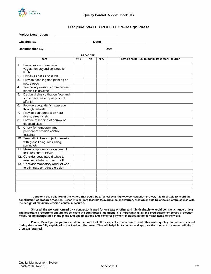
Quality Control Review Checklists
Quality Management System 07/24//2013 Rev. 1.0 Appendix D 22
Discipline: WATER POLLUTION-Design Phase
Project Description: Checked By: _________________________ Date: _________________________ Backchecked By: _________________________ Date: _________________________ PROVIDED
Item Yes No N/A Provisions in PSR to minimize Water Pollution
1. Preservation of roadside vegetation beyond construction limits
2. Slopes as flat as possible
3. Provide seedling and planting on new slopes
4. Temporary erosion control where planting is delayed
5. Design drains so that surface and subsurface water quality is not affected
6. Provide adequate fish passage through culverts
7. Provide bank protection near rivers, streams etc.
8. Provide reseeding of borrow or disposal sites
9. Check for temporary and permanent erosion control features
10. Treat all ditches subject to erosion with grass lining, rock lining, paving etc.
11. Make temporary erosion control features part of PS&E
12. Consider vegetated ditches to remove pollutants from runoff
13. Consider mandatory order of work to eliminate or reduce erosion
To prevent the pollution of the waters that could be affected by a highway construction project, it is desirable to avoid the construction of erodable features. Since it is seldom feasible to avoid all such features, erosion should be attacked at the source with the design of maximum erosion control measures. Since all the work performed by a contractor is paid for one way or other and it is desirable to avoid contract change orders and important protections should not be left to the contractor’s judgment, it is important that all the predictable temporary protection measures be incorporated in the plans and specifications and items for payment included in the contract items of the work. Project Development personnel should ensure that all aspects of erosion control and other water quality features considered during design are fully explained to the Resident Engineer. This will help him to review and approve the contractor’s water pollution program required.
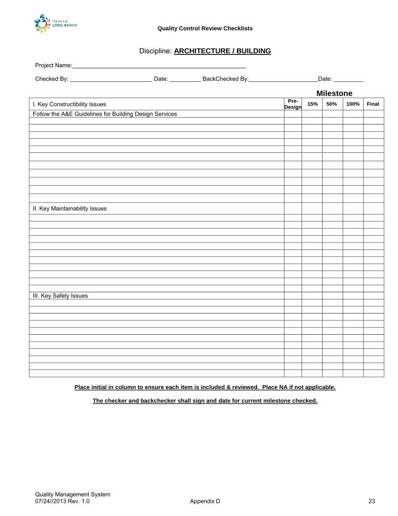
Quality Control Review Checklists
Quality Management System 07/24//2013 Rev. 1.0 Appendix D 23
Discipline: ARCHITECTURE / BUILDING
Project Name: Checked By: Date: BackChecked By: Date:
Milestone
I. Key Constructibility Issues Pre- Design
15% 50% 100% Final
Follow the A&E Guidelines for Building Design Services
II. Key Maintainability Issues III. Key Safety Issues
Place initial in column to ensure each item is included & reviewed. Place NA if not applicable.
The checker and backchecker shall sign and date for current milestone checked.
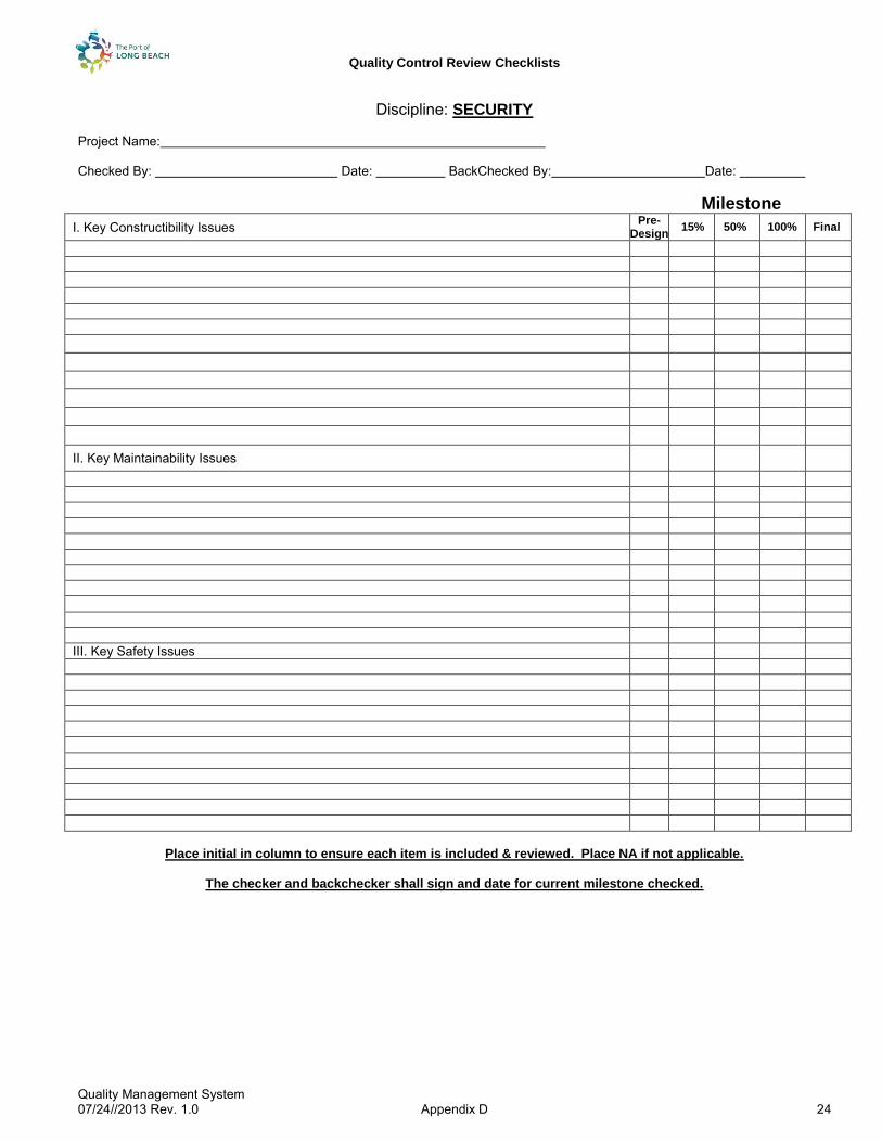
Quality Control Review Checklists
Quality Management System 07/24//2013 Rev. 1.0 Appendix D 24
Discipline: SECURITY Project Name: Checked By: Date: BackChecked By: Date:
Milestone
I. Key Constructibility Issues Pre- Design
15% 50% 100% Final
II. Key Maintainability Issues III. Key Safety Issues
Place initial in column to ensure each item is included & reviewed. Place NA if not applicable.
The checker and backchecker shall sign and date for current milestone checked.

Quality Control Review Checklists
Quality Management System 07/24//2013 Rev. 1.0 Appendix D 25
Discipline: COMMUNICATIONS
Project Name: Checked By: Date: BackChecked By: Date:
Milestone
I. Key Constructibility Issues Pre- Design
15% 50% 100% Final
II. Key Maintainability Issues III. Key Safety Issues
Place initial in column to ensure each item is included & reviewed. Place NA if not applicable.
The checker and backchecker shall sign and date for current milestone checked.

Quality Control Review Checklists
Quality Management System 07/24//2013 Rev. 1.0 Appendix D 26
Discipline: SPECIFICATIONS
Project Name: Checked By: Date: BackCheckBy: Date:
Milestone
I. Key Constructibility Issues Pre- Design
15% 50% 100% Final
II. Key Maintainability Issues III. Key Safety Issues
Place initial in column to ensure each item is included & reviewed. Place NA if not applicable.
The checker and backchecker shall sign and date for current milestone checked.

Quality Control Review Checklists
Quality Management System 07/24//2013 Rev. 1.0 Appendix D 27
Discipline: CONSTRUCTION
Project Name: Checked By: Date: BackChecked By: Date: Milestone
I. Key Constructibility Issues Pre-
Design 15% 50% 100% Final
1. Any conflicts with on going contracts/projects 2. All necessary permits to construct/enter identified and acquired 3. SWPPP 4. Construction easements adequate 5. Safety 6. Cross sections are developed as required 7. Typical cross sections includes existing conditions 8. Number of working days sufficient for the type of work 9. Liquidated damages calculated per project’s complexity 10. Lane and track closure charts’ times and days are realistic 11. Detours, Traffic Handling plans and stage construction plans are included as required 12. Utility Plans complete and high risk utilities identified and located on plans 13. Construction Details are complete and constructible 14. Log of Test Borings included for all retaining projects 15. Drainage profiles included as required. Alternative pipe culvert table included 16. Railroad involvement on plans resolved 17. Adequate access as required for residents/business/tenants in areas under construction
is obtained
18. Impacts of construction windows required by environmental Resource Agencies 19. Adequate construction times 20. NPDES Storm water quality team 21. Previous review comments resolved and incorporated II. Key Maintainability Issues 1. Are materials Sole Source Materials? Is it avoidable? 2. Provide maintenance access roads with both a way in and a way out 3. Provide maintenance vehicle access and parking 4. Provide adequate access to container loading equipment
III. Key Safety Issues 1. Ensure that the Grading does not impair Sight Distance
2. The Maximum of 2:1 Slopes should not be exceeded when landscape planting is
required.
3. Does roadway placement prevent wrong way moves. 4. Place Cable Railing on Retaining Walls where required. 5. Provide emergency access to various sites at all times 6. Provide adequate space for construction equipment
Place initial in column to ensure each item is included & reviewed. Place NA if not applicable.
The checker and backchecker shall sign and date for current milestone checked.

Quality Control Review Checklists
Quality Management System 07/24//2013 Rev. 1.0 Appendix D 28
Discipline: BID COMPLIANCE
Project Name: Checked By: Date: BackChecked By: Date:
Milestone
I. Key Constructibility Issues Pre- Design
15% 50% 100% Final
1. All items of work shown on Plans specified in specifications and match pay items. Description and unit of measure are consistent in PS&E
2. Railroad involvement on plans resolved
3. Cross sections are developed as required 4. Standard Plans Lists are complete and accurate 5. Typical cross sections includes existing conditions 6. First Layout sheet contains legends, symbols abbreviations not shown on Standard
Plans. All necessary exist facilities shown in dropout
7. Construction Details are complete 8. Drainage profiles included as required. Alternative pipe culvert table included. 9. Detours, Traffic Handling plans and stage construction plans are included as required 10. Summary of Quantities are tabulated & summarized correctly 11. Utility Plans complete & high risk utilities identified & located on plans 12. Log of Test Borings included for all retaining and noise barrier projects 13. Number of working days sufficient for the type of work 14. Liquidated damages calculated per project’s complexity 15. Lane closure charts are included 16. SSPs specify all work to be done in Plans & contract pay items in BEES 17. All SSPs have necessary measurement and payment clauses 18. All SSPs related to obstructions (including high-risk facilities) are included 19. Railroad clauses provided 20. All permits are obtained & requirements needed are incorporated in the PS&E. 21. Supplemental Funds for Maintenance of Traffic included 22. Environmentally Sensitive Areas (ESAs) are identified on plans and included in
specifications
23. Storm Water Pollution Prevention Plan (SWPPP) issues addressed 24. Approval for use of trade names included 25. Availability of water letter on file 26. Previous suggestions/corrections addressed 27. Access to lease properties and right of way easements
Place initial in column to ensure each item is included & reviewed. Place NA if not applicable.
The checker and backchecker shall sign and date for current milestone checked.
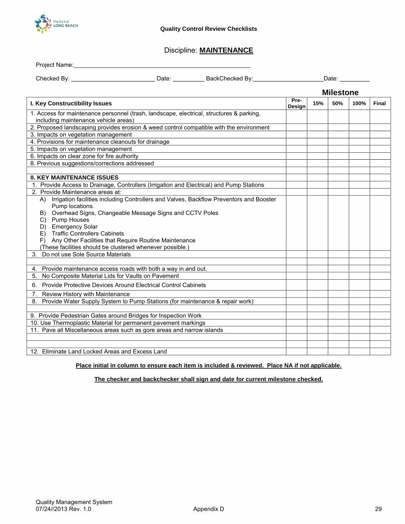
Quality Control Review Checklists
Quality Management System 07/24//2013 Rev. 1.0 Appendix D 29
Discipline: MAINTENANCE
Project Name: Checked By: Date: BackChecked By: Date:
Milestone
I. Key Constructibility Issues Pre-
Design 15% 50% 100% Final
1. Access for maintenance personnel (trash, landscape, electrical, structures & parking, including maintenance vehicle areas)
2. Proposed landscaping provides erosion & weed control compatible with the environment 3. Impacts on vegetation management 4. Provisions for maintenance cleanouts for drainage 5. Impacts on vegetation management 6. Impacts on clear zone for fire authority 8. Previous suggestions/corrections addressed II. KEY MAINTENANCE ISSUES 1. Provide Access to Drainage, Controllers (Irrigation and Electrical) and Pump Stations 2. Provide Maintenance areas at:
A) Irrigation facilities including Controllers and Valves, Backflow Preventors and Booster Pump locations.
B) Overhead Signs, Changeable Message Signs and CCTV Poles C) Pump Houses D) Emergency Solar E) Traffic Controllers Cabinets F) Any Other Facilities that Require Routine Maintenance (These facilities should be clustered whenever possible.)
3. Do not use Sole Source Materials 4. Provide maintenance access roads with both a way in and out. 5. No Composite Material Lids for Vaults on Pavement 6. Provide Protective Devices Around Electrical Control Cabinets
7. Review History with Maintenance 8. Provide Water Supply System to Pump Stations (for maintenance & repair work) 9. Provide Pedestrian Gates around Bridges for Inspection Work 10. Use Thermoplastic Material for permanent pavement markings 11. Pave all Miscellaneous areas such as gore areas and narrow islands 12. Eliminate Land Locked Areas and Excess Land
Place initial in column to ensure each item is included & reviewed. Place NA if not applicable.
The checker and backchecker shall sign and date for current milestone checked.

Quality Control Review Checklists
Quality Management System 07/24//2013 Rev. 1.0 Appendix D 30
Milestone
MAINTENANCE QC CHECKLIST (PAGE 2 OF 2)
II. KEY MAINTENANCE ISSUES (continued) Pre- Design
15% 50% 100% Final
13. List below any other safety considerations not previously identified. 14. Provide updated As-Builts for all projects as soon as the project is complete. 15. Provide adequate acceleration lengths to safely merge onto the roadway Maintainable Ideals
1. Must have a Predictable Maintenance Cycle 2. Must have a Predictable Life Cycle Cost 3. The Maintenance effort at each cycle must be achievable without adversely affecting
customer service (the motoring public)
4. Work can be done utilizing existing equipment and facilities 5. The Maintenance Work must be clearly achievable and consistent with public and
worker safety.
Place initial in column to ensure each item is included & reviewed. Place NA if not applicable.
The checker and backchecker shall sign and date for current milestone checked.

Quality Control Review Checklists
Quality Management System 07/24//2013 Rev. 1.0 Appendix D 31
Discipline: (_______________)
Project Name: Checked By: Date: BackChecked By: Date:
Milestone
I. Key Constructibility Issues Pre- Design
15% 50% 100% Final
II. Key Maintainability Issues III. Key Safety Issues
Place initial in column to ensure each item is included & reviewed. Place NA if not applicable.
The checker and backchecker shall sign and date for current milestone checked.

Quality Control Review Checklists
Quality Management System 07/24//2013 Rev. 1.0 Appendix D 32
REVIEW MATRIX
DESIGN
15%
50%
100
%
CONSTRUCTIBILITY
15%
50%
100
%
BIDDABILITY
15%
50%
100
%
1 Basis of Design X 20 Unique Construction Methods X 41 Work Items Versus Bid Items X X
2 Design Criteria X 21 Long Lead Items X X X 42 Quantities Match Between Plans, Specs, Proposal
and Bid, Notice Inviting BidsX
3 Project Criteria X X 22 Check Phasing Sequence X X 43 Bid Duration X
4 Comprehensiveness of Project Planning X 23 Specification Outline X 44 Mobilization / Demobilization Provisions X X
5 Adequacy of Schedule X X X 24 Material Alternatives X X 45 Contacts for Outside Agencies X
6 Comprehensiveness of Budget X X X 25 Phasing / Scheduling Alternatives X X 46 Updated Material Callouts X
7 Budget Multipliers X X X 26 Plans / Completeness X X 47 Bidder Question Procedure X
8 Alternatives X X 27 Plan / Specification Coordination X 48 Pre-Bid Conference X
9 Design Assumptions X X 28 Site Limitations / Restrictions X X 49 Documents Required With Bid X
10 Analysis Methods X 29 Site Access X X 50 Licenses / Certificates Required at Time of Bid X
11 Refined Budget X X 30 Contractor's Work Area X 51 Bid Opening Procedures X
12 Check Partial Plans X 31 Material Laydown Area X
13 Design Meets Project Requirements X X 32 Contract Provisions for Port X
14 Specification Outline X 33 Contract Provisions for Tenant X
15 Unique Specification Draft X 34 Other Contractor Interference X X
16 Check Pre-Final Plans X 35 Early Milestones X X
17 Independent Calculation Check X 36 Owner Supplied Materials / Work X
18 Specifications X 37 Tenant Supplied Materials / Work X
19 Plans / Specification Coordination X 38 Other Supplied Materials / Work X
39 Bonus / Liquidated Damages / Incentive Provisions X
40 Acceptance Criteria X
15% 50% 100% (Pre-Final) Final
- Basis of Design - Alternatives Analysis - Develop Specifications - Revise PS&E- Project Planning - Final Quantities Check- Project Criteria/Scope - Final Estimates- Construction Methods - Assumptions Detailed - Develop Plans- Conceptual Budget - Coordinate P&S
-
- Internal QC
CRITERIA DEVELOPMENT PRELIMINARY ENGINEERING FINAL DESIGN
GENERAL REVIEW PROCESS
Action Items - Tasks
Independent Calc. Check (If required)Check Final Plans
Document Coordination, Plans With Specs/Bid Items and Quantities
Confirm Chosen Alternative
Confirm AssumptionsCheck Initial Plans
Possible review points with
type of review noted
Sanity Check on Basis of Design
Look for Errors in Judgment
Uncover Missing Critical Areas
Project
Start
Confirm Analysis Techniques
ConstructibilityBiddability
Complete Final Bid
Documents
Confirm Project Criteria Met
Review Review
Prepare Calculations and
Final Design
Develop Conceptual
Design
Develop Basic Project
RequirementsReview
Internal Check of Calculations
-Methodology of Analysis Determined
Develop Engineer's Estimate
Refine Conceptual Budget
-
-

Quality Control Review Checklists
Quality Management System 07/24//2013 Rev. 1.0 Appendix D 33
GLOSSARY Basis of Design: A document that describes the basis for the design of the Project, including but not limited to a description of the Project, Scope of Work, Permits, Codes, Standards, Assumptions, Design Criteria, Existing Conditions, Research Sources, Schedules and Budget. This document is formally done on large complex Projects. Budget Multipliers: Multipliers are percentages added as contingencies to various budget sub categories such as labor, materials, professional services, other. The estimating procedures provide guidance on how much to apply at the various stages of the project. In general, the early stages have higher percentages due to the higher amounts of unknown factors, while in the later stages the percentages drop. Contract Provisions for Port: Provisions in Contract Documents describing what the Port participation in the Project will be including inspection, testing, materials supplied, work provided, payment provisions, acceptance criteria. These are in the General Provision of the Specifications and may be modified in the Technical Specifications or Special Provisions of the Specifications. Contract Provisions for Tenant: Provisions in the Contract Documents describing what the Tenant participation in the Project will be including: site clearing, providing access, providing security, restricting access, restricting work schedules, requiring cooperation, attendance at project meetings, approval of work plans and schedules. These provisions mainly are discussed in Special Provisions of the Specifications. Contractor’s Work Area: The area set aside in the Port for the Contractor to set up a trailer and keep materials and equipment. It is desirable for this area to be in or adjacent to the Project Limits. Design Criteria: Specific criteria dealing with codes, loads or forces, standards, and quality. It generally is a set of standards or values upon which a design is based. Long Lead Items: Items of material supply requiring a long time to provide to the job site. Sometimes this term refers to a contract item including constructing or installing the supplied item. Material Laydown Area: An area separate from the Contractor’s Work Area that is specific for storage and laydown of the Project materials. Generally, this is needed for large size materials such as rail, structural steel and timber trusses plus large equipment. Project Criteria: Criteria that is set by the Port and Tenant describing the resulting development. It includes such things as terminal throughput, terminal static capacity, ingress/egress needs, facility quality, operating conditions, design life, budget, etc. Project Planning: Planning that refines the Master Planning and adapts it to the Project site. It includes such things as terminal layouts, traffic flow plans, process flow diagrams, building functions and sizes, infrastructure plans, etc. Site Limitations / Restrictions: Constraints on the site limiting or restricting the Contractor’s activities including such things as working schedule, clearances to adjacent facilities, access points, interruptions, falsework limits, etc. Unique Construction Methods: Methods that are unusual or not considered the norm in port construction should be analyzed to a level that ensure its feasibility early in the Project design process. Unique methods might include extraordinary construction equipment, limited availability of equipment, twenty-four hour construction activities, critical scheduling with high damage potential for infrastructure outages, restrictions on falsework usage, etc. Unique Specification: A specification that has not been used or developed before. In the development of a specification outline the designer shows the normally accepted specification sections as well as new ones. The new ones should have the draft language prepared at the 50%-75% completion stage in order for it to get more review.
REVIEW STEPS The actual steps to perform a project review are shown in Table 1. These steps should be independent of whether the designer is the Port or Consultant, or whether the reviewer is the Port or Consultant. You will note the Project Manager is the central point of control. The Review Team Leader is identified by the Project Manager under direction of Senior Engineering Management. Also shown as Figure 7 is the form to use to provide written comments. These comments are to be kept, including the comment resolution notations, until construction is complete. The QA/QC manual provides more details with respect to record keeping. It is important to note that the Project Manager should provide clear instructions to the reviews as to what stage the project is in (15%, 50%, 100% or other) so the previously described listing of review items and issues can be efficiently addressed.

Quality Control Review Checklists
Quality Management System 07/24//2013 Rev. 1.0 Appendix D 34
REVIEW STEPS The actual steps to perform a project review are shown in Table 1. These steps should be independent of whether the designer is the Port or Consultant, or whether the reviewer is the Port or Consultant. You will note the Project Manager is the central point of control. The Review Team Leader is identified by the Project Manager under direction of Senior Engineering Management. Also shown as Figure 7 is the form to use to provide written comments. These comments are to be kept, including the comment resolution notations, until construction is complete. The QA/QC manual provides more details with respect to record keeping. It is important to note that the Project Manager should provide clear instructions to the reviews as to what stage the project is in (15%, 50%, 100% or other) so the previously described listing of review items and issues can be efficiently addressed.

Quality Control Review Checklists
Quality Management System 07/24//2013 Rev. 1.0 Appendix D 35
E-1
PROJECT REVIEW STEPS
1. Port’s Project Manager to schedule review of project with the Review Team Leader.
2. Project Review Team Leader and Project Manager agree on type of review and stage of completion and which engineering discipline representatives will be required for the review, including level of effort and estimated fee.
3. The Project Review Team Leader will notify the review team members of their participation and review schedule.
4. The Project Manager will provide the requested number of plans, specifications and/or calculations for use by the review team.
5. Plans, specifications and/or calculations will be provided to the review team.
6. Each review team member will provide substantial review of the portion of the submittal for which he is responsible. Each team member will also provide cursory review of other portions of the project to avoid conflicts or misrepresentation of information.
7. Review team member will mark or attach comments to the plans, specifications, and/or calculations with an identifying number such as for electrical comment number one (Comment code should be consistent with discipline codes listed on comment form).
8. Reviewed plans, specifications and/or calculations will be returned by the required date to the Review Team Leader.
9. The Review Team Leader or designated staff member will review the design team member’s comments for conflicts or duplication of information.
10. Any conflicts in comments will be resolved by the Review Team Leader and the team members.
11. All reviewed submittals including comments will be returned to the designer through the Port’s Project Manager.
12. The designers shall address the comments and complete the resolution portion on the Comment Form.
13. If the designer has any concerns about certain comments, the concern should be quickly transmitted to the Port’s Project Manager for resolution.
14. For the next submittal, the designer is to submit revised or finalized plans, specifications and/or calculations together with the originally reviewed submittals and a written listing of the review comments with resolution comments. Significant comment resolution between the designer and reviewer should occur prior to the next submittal.
15. This next submittal will go to the Project Review Team Leader for the appropriate action of 1) review for compliance 2) further review 3) recommendation for acceptance. The decision to do a review for compliance (1) or recommendation for acceptance (3) will be based on who is the designer and reviewer, the complexity of the Project, any outside requirements, and Senior Engineering Management direction.

Quality Management System 07/24/13 – Rev. 1.0
Appendix E
Contents:
Sample Surveillance/Audit Report
Sample Performance Metrics
Sample Dashboard
Quality Assurance Planning Log

QUALITY SURVEILLANCE/AUDIT REPORT
Appendix E 1
Project Name Review Milestone
Quality Surveillance/Audit Report Conducted for
Program Management Division
PQM, Inc. 16742 Gothard Street, Suite 223 Huntington Beach, CA 92647 Office: 714.969.6825 www.pqminc.com
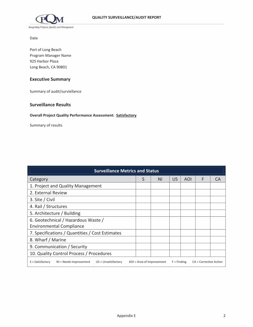
QUALITY SURVEILLANCE/AUDIT REPORT
Appendix E 2
Date
Port of Long Beach Program Manager Name 925 Harbor Plaza Long Beach, CA 90801
Executive Summary
Summary of audit/surviellance
Surveillance Results
Overall Project Quality Performance Assessment: Satisfactory
Summary of results
Surveillance Metrics and Status
Category S NI US AOI F CA 1. Project and Quality Management 2. External Review 3. Site / Civil 4. Rail / Structures 5. Architecture / Building 6. Geotechnical / Hazardous Waste / Environmental Compliance
7. Specifications / Quantities / Cost Estimates 8. Wharf / Marine 9. Communication / Security 10. Quality Control Process / Procedures S = Satisfactory NI = Needs Improvement US = Unsatisfactory AOI = Area of Improvement F = Finding CA = Corrective Action

QUALITY SURVEILLANCE/AUDIT REPORT
Appendix E 3
Corrective Actions
Corrective Action Required: None Due Date for Corrective Action: N/A
General Information
POLB Project Manager: POLB Program Manager: Audit Conducted By: Auditor Name Location of Audit: Consultant Name
Address Address
Date Audit Conducted: Date Personnel Present: Name, Title, Company
Name, Title, Company Draft Report Date: Date Final Report Date: Date Distribution: Name, Title, Company Name, Title, Company Name, Title, Company Attachments:
Submitted By, Name, Title PQM, Inc.

QUALITY SURVEILLANCE/AUDIT REPORT
Appendix E 4
Categories & Questions Response Details
1. Project and Quality Management
Is the key management team participating in the quality program? Principal? Project Manager? Quality Manager?
What is the Scope of Work? Deliverables? Submittal Packages? Milestone Submittal?
What is the original schedule for this submittal? Is it on schedule? If not, describe why.
Where is production taking place? How did the quality oversight take place? Primary location?Remote offices? Subconsultant offices?
Was the Itemized Submittal List provided to the POLB QAM in advance of the audit/surveillance?
Was the QC Activity schedule completed and provided? Does the actual schedule closely match the planned schedule?
Is a Risk Identification Log maintained? Was an Assessment of the Risks conducted? Was the Risk Register distributed to the Project Team who needs to know this information?
What method is being used to track action items?
Does the Design Control Log apply to this milestone? If yes, is it completed and distributed to the Project Team?
Does the prime consultant verify the subconsultants QMP compliance?

QUALITY SURVEILLANCE/AUDIT REPORT
Appendix E 5
Categories & Questions Response Details
Is the interface management taking place routinely? Describe the meetings that routinely take place.
What method is used for Project Document Control?
What method is used for Quality Records Management?
Are the documents organized per the contract requirements?
Overall Project and Quality Management Performance Assessment Satisfactory
2. External Review
Were the Comment, Response, and Resolution log sheet used properly?
Did all required Reviewers complete their review and document their comments on the form?
Did the Designer prepare responses to the comments and return them to the Reviewer timely?
Overall External Review Performance Assessment Satisfactory
3. Site / Civil
Are impacts to adjacent property determined?
Were utilities field located? Pothole?
What assumptions are made?
Has access been cleared by Traffic and other departments?
Overall Site / Civil Performance Assessment Needs Improvement

QUALITY SURVEILLANCE/AUDIT REPORT
Appendix E 6
Categories & Questions Response Details
4. Rail / Structures
Does rail alignment meet design criteria?
Are structures included with this submittal? Bridges? Retaining Walls? Sound Walls?
Are the calculations prepared and checked in accordance with the Checking Calculations Procedure?
Has the Independent Check of Structures been completed? What is the status?
Were As-Built Drawings used to support assumptions? If yes, please explain.
Are the quantity calculations prepared orderly and neatly? Are they checked in accordance with the QMP?
Was the POLB Comment, Response and Resolution Log Sheet used?
Are the Specification (SSPs and) checked?
Overall Rail / Structures Performance Assessment Unsatisfactory
5. Architecture / Building
Are the documents that are listed on the Itemized Submittal List available and included with the submittal?
Are the Discipline Review quality records available for review?
Are all of the drawings listed on the Itemized Submittal List included in this submittal? If not, which drawings are missing?
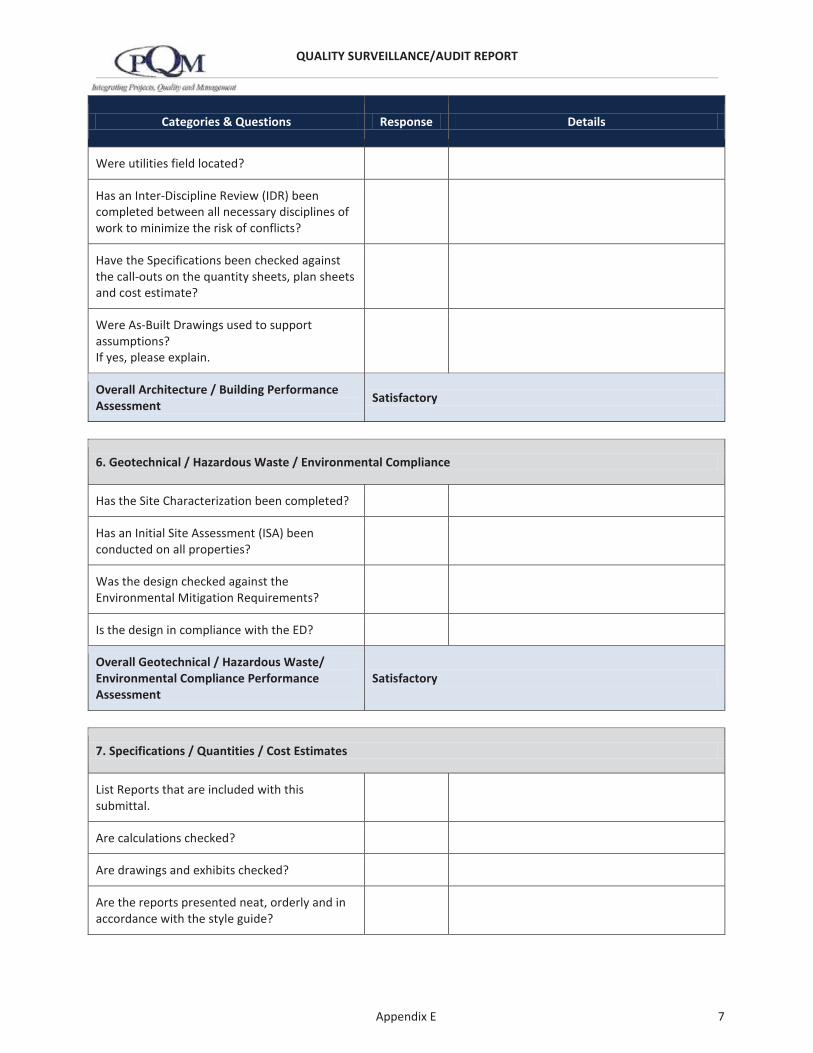
QUALITY SURVEILLANCE/AUDIT REPORT
Appendix E 7
Categories & Questions Response Details
Were utilities field located?
Has an Inter-Discipline Review (IDR) been completed between all necessary disciplines of work to minimize the risk of conflicts?
Have the Specifications been checked against the call-outs on the quantity sheets, plan sheets and cost estimate?
Were As-Built Drawings used to support assumptions? If yes, please explain.
Overall Architecture / Building Performance Assessment Satisfactory
6. Geotechnical / Hazardous Waste / Environmental Compliance
Has the Site Characterization been completed?
Has an Initial Site Assessment (ISA) been conducted on all properties?
Was the design checked against the Environmental Mitigation Requirements?
Is the design in compliance with the ED?
Overall Geotechnical / Hazardous Waste/ Environmental Compliance Performance Assessment
Satisfactory
7. Specifications / Quantities / Cost Estimates
List Reports that are included with this submittal.
Are calculations checked?
Are drawings and exhibits checked?
Are the reports presented neat, orderly and in accordance with the style guide?

QUALITY SURVEILLANCE/AUDIT REPORT
Appendix E 8
Categories & Questions Response Details
Has the report been checked by a minimum of two people?
Has the body of the report been checked and confirmed against the appendices, exhibits, tables, etc.?
Was a cost estimate completed for this milestone?
Is there evidence that the accuracy check of the quantities was completed? Are the calculations presented neatly and orderly? If a spreadsheet was used, were the cell calculations checked?
Is there sufficient evidence that a “Reasonableness Check” was conducted?
Explain how the unit costs were determined?
Has the engineer’s construction cost substantially changed since the prior submittal?
Overall Specifications / Quantities / Cost Estimates Performance Assessment Satisfactory
8. Wharf / Marine
Has the design been checked against the Wharf Design Criteria?
Have the Load Calculations been completed?
Are all of the drawings listed on the Itemized Submittal List included in this submittal? If not, which drawings are missing?
Has an Inter-Discipline Review (IDR) been completed between all necessary disciplines of work to minimize the risk of conflicts?
Overall Wharf / Marine Performance Assessment Satisfactory

QUALITY SURVEILLANCE/AUDIT REPORT
Appendix E 9
Categories & Questions Response Details
9. Communication / Security
Are the documents that are listed on the Itemized Submittal List available and included with the submittal?
Overall Communication / Security Performance Assessment Satisfactory
10. Quality Control Process / Procedures
Were accuracy checks conducted prior to the discipline Review?
Was a Discipline Review conducted before the Inter-Discipline Review?
Was an Inter-Discipline Review completed? Did all applicable disciplines participate?
Did a Constructability Review take place as part of the quality reviews for this submittal?
Did a Management Review and QA Certification take place?
Are the quality program mechanics being properly followed? Use of a color code system? Use of the Check Print stamps? Use of the Review Print stamp? Use of Checklists?
Software selection and validation?
Checking Calculations?
Checking Drawings?
Checking Reports?
Checking Specifications?
Overall QC Process / Procedures Performance Assessment Satisfactory

Technical Project Performance Indicators
POLB Quality Assurance ProgramPrepared by PQM, Inc.12/21/2012 Rev 0 Appendix E
POLB PM:
POLB QM:
Design Manager/Firm:
1
2
3
1
2
3
1
2
3
1
2
3
1
2
3
1
2
3
1
2
3
1
2
3
1
2
3
1
2
3
1
2
3
Close-Out:
3Alternative Analysis /
Basis of Design
1
Project NameFeasibility / Pre-Design
Comments
Legend
9
Overall Status
Yellow Red Grey
8Quality Control
Process / Procedures
Project and Quality Management
2 External Review
Submittal Information
Item
#
Disciplines of Work FirmEngineering & EnvironmentalTechnical Reports / Studies
11
GreenSatisfactory Needs Improvement Unsatisfactory Not Performed
10
5Stakeholder
Involvement / Outreach
6Environmental
Document
4Environmental
Technical Studies
Engineering7
Initial Assessment
Project Metrics and Status
Pre-DesignEnvironmentalDocument
1 2 3

Technical Project Performance Indicators
POLB Quality Assurance ProgramPrepared by PQM, Inc.12/21/2012 Rev 0 Appendix E
POLB PM:
POLB QM:
Design Manager:
Item
#
Disciplines of Work Firm
1
2
3
1
2
3
1
2
3
1
2
3
1
2
3
1
2
3
1
2
3
1
2
3
1
2
3
1
2
3
1
2
3
Close-Out:
GreyGreenNeeds Improvement
Yellow Unsatisfactory
Red
Project Name(Design / Bid & Award)
Satisfactory Not Performed
11 Overall Status
Submittal Information
5 Architecture / Building
4 Rail / Structures
15%Design
3 Site / Civil
2 External Review
Action Items
1 Project and Quality Management
8 Wharf / Marine
7Specifications /
Quantities / Cost Estimates
6
Geotechnical / Hazardous Waste /
Environmental Compliance
Bid & Award
Project Metrics and Status
Initial Assessmen
t50% 100% Final
Legend
10 Quality Control Process / Procedures
9 Communication / Security

Technical Project Performance Indicators
POLB Quality Assurance ProgramPrepared by PQM, Inc.12/21/2012 Rev 0 Appendix E
POLB PM:
POLB QM:
Item
#
Categories Firm
1
2
3
1
2
3
1
2
3
1
2
3
1
2
3
1
2
3
1
2
3
1
2
3
1
2
3
1
2
3
1
2
3
Close-Out:Satisfactory Needs Improvement Unsatisfactory Not Performed
Green Yellow Red Grey
Overall Status
Legend
9 QC Process / Procedures
10
11
7 Budget
8 Schedule
5 CCOs
6 Contingency Balance
3 Construction Quality
4 RFIs
1 Construction Management
2 Design Quality
Submittal Information Project Metrics and Status
Comments10% 25% 50% 75% 100%
Project Name(Construction)
Construction Manager:
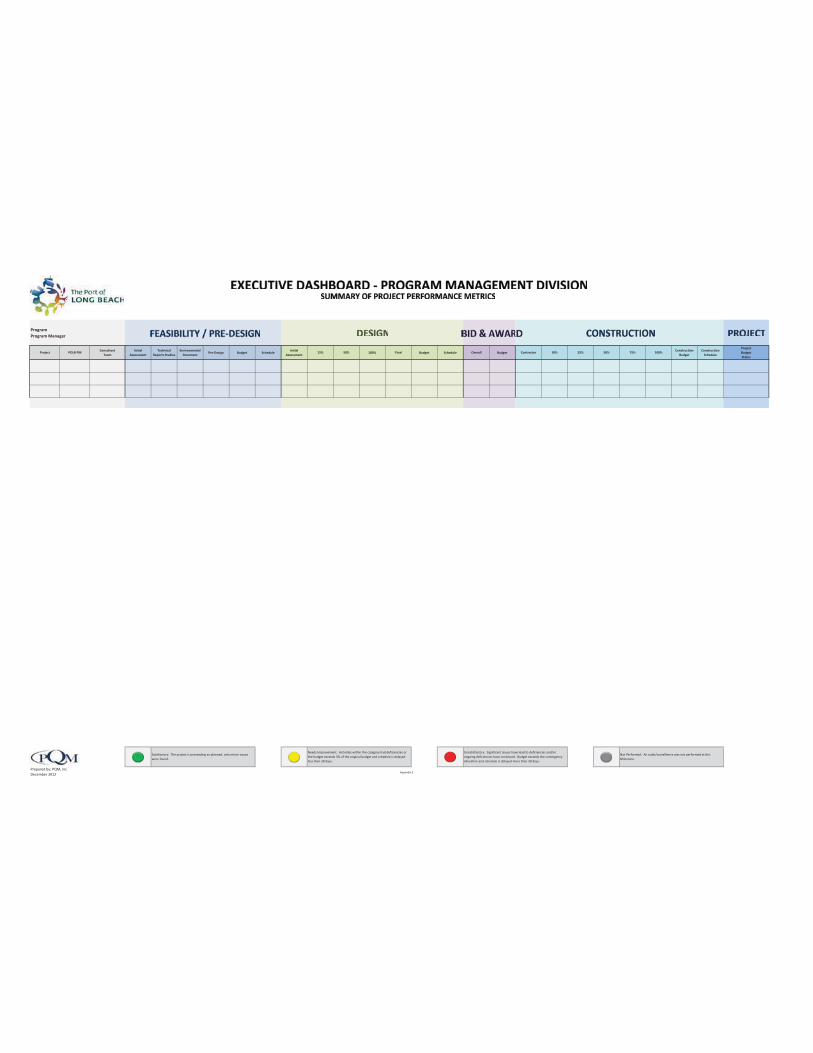
Appendix E
ProgramProgram Manager
Project POLB PM ConsultantTeam
Initial Assessment
Technical Reports Studies
Environmental Document
Pre-Design Budget ScheduleInitial
Assessment15% 50% 100% Final Budget Schedule Overall Budget Contractor 10% 25% 50% 75% 100% Construction
BudgetConstruction
Schedule
ProjectBudgetStatus
Prepared by: PQM, IncDecember 2012
Needs Improvement: Activities within the category had deficiencies or the budget exceeds 3% of the original budget and schedule is delayed less than 30 days.
Unsatisfactory: Significant issues have lead to deficiencies and/or ongoing deficiencies have continued. Budget exceeds the contingency allocation and schedule is delayed more than 30 days.
Not Performed: An audit/survellience was not performed at this Milestone.
Satisfactory: The project is proceeding as planned, only minor issues were found.

Quality Assurance Planning Schedule
QA Planning SchedulePrepared by PQM, Inc. 12/21/2012 Rev 0 Appendix E
Checklist No. ___________
ItemElement
CharacteristicFirm
QA/QCPlan
Approval
InitialPlanned
Surveillance
SubmittalDate
InitialPlanned
Audit
ScheduledAudit
RecordsTurnover
Closeout
1
2
3
4
Page No. ___ of ___