good neighbor: ad hoc pairing of nearby wireless devices by
TRANSCRIPT

Good Neighbor: Ad Hoc Pairing of Nearby Wireless Devices byMultiple Antennas
Liang Cai Kai Zeng Hao Chen Prasant MohapatraComputer Science Department, UC Davis
[email protected] {kzeng,hchen,prasant}@cs.ucdavis.edu
Abstract
The proliferation of personal wireless devices requires secure connection between them. While itis easy to securely pair electronic devices by wires, it is very challenging to pair them wirelessly whenthey have no prior association. We propose Good Neighbor, a novel scheme that securely pairs nearbywireless devices by exploiting multiple antennas built in them. Our scheme requires neither shared se-crets nor out-of-band channels (e.g., audio, visual, keyboard, etc.) between the pairing devices. It onlyrequires that the receiver has multiple antennas and that the sender can be placed nearby the receiver.Our scheme is based on the propagation characteristic of thewireless signal that the power of the re-ceived signal is inversely proportional to some exponent ofthe distance between the sender and receiver.When a nearby sender moves very close to one antenna on the receiver, the receiver can observe a largedifference between the signal strength measured on its two antennas, whereas a faraway sender wouldbe unable to induce such a large difference. We validate our scheme through theoretical analysis and ex-perimental measurements. We discuss the factors that may affect our scheme — including antenna gain,received signal strength (RSS) saturation, dynamic rate adaptation, and multipath effects — and how tomitigate them. Finally, we demonstrate the practicality ofour scheme by implementing and evaluating aprototype.
1 Introduction
The proliferation of wireless devices requires secure connection between these devices. How to setup a secure connection between two previously unassociated devices remains an important yet challengingproblem. Most current schemes rely on a common secret to bootstrap the secure connection. However,creating a strong secret and delivering it to both devices often poses usability challenges. First, users areknown not to be competent at creating strong secrets. Second, users have to go through different, and oftenlaborious and unintuitive, procedures to enter the secret on differentdevices. This mechanism becomes evenmore problematic for devices with no keyboard, such as wireless headphones. In this case, manufacturersoften hardcode the secret in the device and print it in the manual. For usability reasons, manufacturers tendto choose easy-to-remember secrets, such as0000 for many bluetooth headphones, which unfortunatelycompletely defeats the purpose of shared secrets.
Moreover, we often need to set up ad hoc, temporary connections between nearby devices. For example,two business people wish to exchange contact information via their cell phones, and a group of tourists wishto exchange photos in their wireless-capable cameras. We can establish such ad hoc connections betweenunassociated devices easily via wires, but to do so wirelessly is very challenging. This problem is calledSecure Device Paring.
TheWi-Fi Protected Setup(WPS) [2] standard fromWi-Fi Alliancespecifies four device pairing meth-ods. (1) PBC method: the user pushes a hardware or software button onboth devices; (2) PIN method: theuser reads a PIN from one device and enters it at the other; (3) NFC (Near Field Communication) method:the user brings the devices close enough to allow near field communication between them (such as RFID
1

tags); (4) USB method: the user transfers data between the devices usingeither a USB flash drive or a USBcable. Approaches proposed by researchers for secure device pairing, including the above four methods, fallinto two categories: (1) based on out-of-band channels, and (2) based on proximity.
Kobsa, et al. [9] compared device pairing schemes based on out-of-band channels, such as acous-tic [16, 5], visual [13, 20], and motion [12, 7]. These schemes requireeither sensors — such as cameras,microphones, or accelerometers – or peripherals, such as displays or keyboards. As wireless capability isexpanding to a wide variety of devices (such as cameras, scanners, oreven digital picture frames) that donot have these sensors or peripherals, the scope of applicability of these schemes is limited.
Alternatively, device pairing can be based on proximity. In many circumstances, the adversary cannotcome close to the user’s devices (or cannot do so without being detected). Frank Stajano described manyscenarios where the user wishes to pair any devices within proximity [23]. Using a USB cable is a form ofproximity-based pairing; however, since it requires a cable and USB interfaces on both devices, its appli-cability is limited. The NFC method in WPS is also a proximity-based method; however, itis vulnerableto attacks using powerful transmitting and receiving antennas. Distance bounding protocols are resilientto these attacks; however, since they require highly precise clocks (of nanosecond precision) because elec-tromagnetic waves propagate over 30cm in 1 nanosecond, they are unsuitable for many consumer wirelessdevices.
We propose a simple yet reliable proximity-based device pairing scheme by taking advantage of multipleantennas available on many modern wireless devices. Our scheme only requires that one of the pairingdevices has at least two antennas (We call the device with multiple antennas thereceiver, and the other onethesender. If both devices have multiple antennas, either one can serve as the receiver). Our scheme requiresneither shared secrets nor out-of-band channels between the devices. Our key insight is that the differencein the received signal strengths (RSS) on different antennas on the receiver can imply if the sender is nearby.RSS is inversely proportional to some exponent of the distance between thesender and the receiver. Whenthe user places the sender very close to one antenna on the receiver, the receiving signal strength on thisantenna would be far greater than that on the other antennas on the receiver. By contrast, when the senderis far from the receiver, it is of similar distance from all the antennas on thereceiver and therefore wouldbe unable to cause a large difference in the RSS values. Although a faraway attacker can attack the NFCmethod by increasing its transmitting power, such an attack has no effect on our method because transmittingpower does not affect the RSS ratio between different antennas on thereceiver.
Since our scheme requires neither sensors nor peripherals, it can be applied to simple wireless deviceslike Eye-Fi [1] cards. Our scheme requires that one of the pairing devices has at least two antennas. Eventhough not all the wireless devices have multiple antennas yet, we expect multiple antennas to becomewidely available soon as wireless devices embrace themultiple-input multiple-output(MIMO) technologyproposed in IEEE 802.11n to increase their maximum raw data rates.
Although multiple RSS values have been explored for location inference [10, 24], we are the first, tothe best of our knowledge, to apply it to secure device pairing. Since device pairing requires a much moreprecise estimation of proximity than the previous schemes [10, 24], as the attacker may come within areasonable distance from the user’s wireless device (e.g., at an airport lounge), we need to overcome a seriesof challenges (Section 4) in designing our scheme.
2 Proximity detection based on differential RSS
Compared to the difficulty in pairing wireless devices, pairing wireline devicesis often straightforward:by simply plugging one device into the other. This approach is secure against all adversaries that are phys-ically distant from the pairing devices. Due to the simplicity of this scheme, one naturally wishes to finda similar mechanism to securely pair wireless devices that are in immediate proximity.As is well knownin wireless communication, thereceived signal strength(RSS) depends on the distance between the senderand receiver. A naive idea would be to infer proximity based on the RSS value alone. However, a far-
2

away attacker could defeat this naive scheme by sending powerful signal to induce large RSS values on thereceiver
We can defeat the above attack if the receiver has two antennas that canmeasure RSS independently.Most recent laptops, including all the laptops with 802.11n MIMO modules, have two or more antennas totake advantage of antenna diversity. Although not all mobile devices currently have multiple antennas, weexpect multiple antennas to appear on these devices soon as they embrace the MIMO technology to improvetheir data rate. Note that our scheme requires only one of the two pairng device to have multiple antennas(we call this device thereceiver, and the other device thesender).
Our key observation is that the ratio between the RSS values measured on themultiple antennas onthe receiver is independent of the sending power. However, the ratio depends on the difference betweenthe distances between the sender and the two receiving antennas. While a nearby sender can make thisdifference large, a faraway sender cannot.
2.1 Theories of RSS
2.1.1 Free space propagation model
In the absence of any reflections or multipath, we can model radio wave propagation using the free spacepropagation model in Equation (1) [18]. The power of the signal at the receiving antenna is:
Pr = PsGsGr(λ
4πd)2. (1)
whereGr andGs are the gain of the receiving and sending antenna respectively,Ps is the power at the surfaceof the sending antenna, andd is the distance between the two antennas.
When we representPr in dBm:
Pr [dBm] = P0−20log(dd0
). (2)
whereP0 is the power of the signal in dBm at distanced0 away from the sender.
2.1.2 Log-normal shadowing model
A more widely used signal propagation model is log-normal shadowing[18].
Pr [dBm] = P0−10αlog(dd0
)+Xσ. (3)
whereP0 is the receiving power at distanced0, α is the path loss exponent, andXσ is a Gaussian noise(random variable) with zero mean and standard deviationσ. The path loss exponentα depends on thespecific propagation environment, i.e., type of construction material, architecture, and location within abuilding. The values ofα range from 1.2 (Waveguide effect) to 8 [14]. In free space,α is 2.
2.2 RSS ratio
Inferring distance by RSS alone is difficult because of the uncertainty ofα and Xσ, especially in adynamic environment. However, for device pairing, the influence from theenvironment is small because thesender and the receiver are close. We evaluate our hypothesis with a series of experiments in Section 4.
The setting of our RSS based proximity inference scheme is shown in Figure 1. The receiver R has twoantennas,A1 andA2, separated by a reasonable distanceL. When R receives a packet, R reads the RSS
3

A1 A2d1
d2
L
d'1d'2
Receiver
Sender
Attacker
Figure 1: Our scheme requires the receiver to be a wireless device with atleast two antennas. We use alaptop equipped with 802.11n MIMO antenna in our prototype system.
values (RSS1 andRSS2) independently onA1 andA2, respectively. Since RSS is a value in dBm1, we termthe difference between two RSS valuer = RSS1−RSS2 asRSS ratio.
We assume that theRSS1 andRSS2 values follow the Log-normal shadowing model. For clarity, we letRSS1 andRSS2 denote the average of sufficient number of RSS measurements so thatXσ can be removed.Therefore, the RSS ratior observed at the receiver is 10αlog(d2
d1). When the sender is placed close toA1, d1
is very small whiled2/d1≈ l/d1 is large, sor becomes a large positive number. Similarly, when the senderis moved toA2, d2 decreases andd2/d1≈ d2/l becomes very small, sor becomes a large negative number.
When an attacker not in the proximity of the receiver sends packets, the RSS ratio r observed at the
receiver is 10αlog(d′2d′1). The largest value of|r| that the attacker can incur is(d′1+ l)/d′1 where the attacker’s
antenna is on the same line ofA1A2 and is closer toA1(or A2). Whend′1 is sufficiently larger thanL, |r| isa small number. In other words, a faraway attacker is unable to yield a largeRSS ratio no matter where theattacker is. Based on this observation, the receiver can choose appropriate thresholdsrH (when the senderis close toA1) andrL (when the sender is close toA2) to distinguish a faraway attacker from a legitimatenearby sender.
3 Design
3.1 Goal and threat model
Our goal is to build a practical, reliable scheme for securely pairing nearbydevices that have no priorassociation. In this paper, we only consider one-way authentication, i.e., only the receiver authenticates thesender but not the other way around. In many scenarios, only one-way authentication is necessary. Forexample, when a user wants to transfer her personal files from the receiver (e.g. laptop) to the sender (e.g.PDA), she only requires the receiver to authenticate the sender. It is straightforward to extend this one-wayauthentication into mutual authentication if the sender also has multiple antennas.
Our scheme requires only that the legitimate sender be physically close to the receiver. We wish toensure that no faraway malicious sender can be paired with the receiversuccessfully. Our scheme can resistpowerful attackers. For example, the attacker may have arbitrarily high transmission power and can adjustthe transmission power arbitrarily; he may sniff all the traffic between the two pairing wireless devices; hemay have exact copies of the two pairing devices and use the copies to attackour scheme; he may know theexact location of the receiver and its antennas; he may send his attack packets via line-of-sight propagation.
1RSSis the ratio of the power of the received signal (P in mW) to 1mW in decibels, i.e.,RSS= 10log10(P).
4
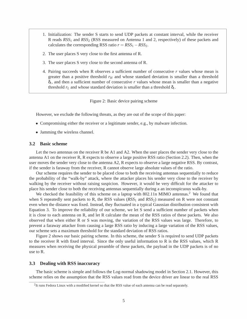
1. Initialization: The sender S starts to send UDP packets at constant interval, while the receiverR readsRSS1 andRSS2 (RSS measured on Antenna 1 and 2, respectively) of these packets andcalculates the corresponding RSS ratior = RSS1−RSS2.
2. The user places S very close to the first antenna of R.
3. The user places S very close to the second antenna of R.
4. Pairing succeeds when R observes a sufficient number of consecutive r values whose mean isgreater than a positive thresholdrH and whose standard deviation is smaller than a thresholdδt , and then a sufficient number of consecutiver values whose mean is smaller than a negativethresholdrL and whose standard deviation is smaller than a thresholdδt .
Figure 2: Basic device pairing scheme
However, we exclude the following threats, as they are out of the scope of this paper:
• Compromising either the receiver or a legitimate sender, e.g., by malware infection.
• Jamming the wireless channel.
3.2 Basic scheme
Let the two antennas on the receiver R be A1 and A2. When the user places the sender very close to theantenna A1 on the receiver R, R expects to observe a large positive RSSratio (Section 2.2). Then, when theuser moves the sender very close to the antenna A2, R expects to observea large negative RSS. By contrast,if the sender is faraway from the receiver, R cannot observe large absolute values of the ratio.
Our scheme requires the sender to be placed close to both the receiving antennas sequentially to reducethe probability of the “walk-by” attack, where the attacker places his sender very close to the receiver bywalking by the receiver without raising suspicion. However, it would be very difficult for the attacker toplace his sender close to both the receiving antennas sequentially during aan inconspicuous walk-by.
We checked the feasibility of this scheme on a laptop with 802.11n MIMO antennas.2 We found thatwhen S repeatedly sent packets to R, the RSS values (RSS1 andRSS2) measured on R were not constanteven when the distance was fixed. Instead, they fluctuated in a typical Gaussian distribution consistent withEquation 3. To improve the reliability of our scheme, we let S send a sufficientnumber of packets whenit is close to each antenna on R, and let R calculate the mean of the RSS ratios ofthese packets. We alsoobserved that when either R or S was moving, the variation of the RSS valueswas large. Therefore, toprevent a faraway attacker from causing a large RSS ratio by inducing alarge variation of the RSS values,our scheme sets a maximum threshold for the standard deviation of RSS ratios.
Figure 2 shows our basic pairing scheme. In this scheme, the sender S is required to send UDP packetsto the receiver R with fixed interval. Since the only useful information to R is theRSS values, which Rmeasures when receiving the physical preamble of these packets, the payload in the UDP packets is of nouse to R.
3.3 Dealing with RSS inaccuracy
The basic scheme is simple and follows the Log-normal shadowing model in Section 2.1. However, thisscheme relies on the assumption that the RSS values read from the device driver are linear to the real RSS
2It runs Fedora Linux with a modified kernel so that the RSS value of eachantenna can be read separately.
5
values. Unfortunately, the RSS values provided by the driver can be distorted due to several factors. Wediscuss these factors and describe how we eliminate or mitigate them.
3.3.1 RSS Saturation
TheRSSvalue reported by the wireless driver (Intel iwlwifi)is an integer in the range [−95,−10]. Thisis usually much smaller than the dynamic range of the actual received signal strength. As we moved thesender from a few meters away to closer to the receiver, at first we observed a continuous increase ofRSS.Then, RSS stopped increasing around the value−10. We conjecture that theRSSvalue reported by thisdriver saturates at the upper bound of−10.
To overcome this problem, we can reduce the transmission power of the sender. But if we reduce thetransmission power too much, we risk saturating RSS at its lower bound. To probe for the best power level,our scheme requires the sender to transmit a sequence of packets using different power levels3 during theinitialization stage of the protocol. The receiver then chooses the power level at which the received packetshave the maximum RSS ratio and notifies the sender. Then, the sender will transmit all the subsequentpackets at this power level.
3.3.2 Automatic Rate adaptation
Another undesirable artifact that affects RSS measurement is automatic rateadaptation. It allows aWi-Fi device to automatically select the optimal data rate for the current wireless channel conditions.
Data rate change may trigger the change of the physical layer preamble modulation scheme, which willaffect theRSSvalues. For example, 802.11g uses the OFDM modulation scheme when the datarate is54Mbps. When the data rate is decreased to 11Mbps or lower (5.5M, 2M or1M), it begins to use CCK,the modulation scheme for 802.11b. Switching between modulation scheme can causes a large variation inreportedRSSvalues, and make our scheme less stable. In a multiple antenna system such as802.11n, theautomatic rate adaptation feature might even change the transmission antenna.This will completely defeatour scheme. Therefore, the automatic rate adaptation feature must be disabled before the packets are sent inour scheme.
3.4 Key generation
The basic protocol in Figure 2 authenticates the sender, but it does not generate a shared secret key forfurther communication. [11, 27] provide approaches to derive a shared key from the characteristics of thewireless channel.
Alternatively, we could use cryptographic techniques to derive a shared secret. Note that key generationdoes not affect the device pairing scheme in Figure 2 and in fact can proceed in parallel with device pairing.This is because the device pairing scheme only measures the RSS value in the preamble of each packet whilekey generation uses the payload of the packet.
We propose a straightforward key generation protocol, where the sender receives a public key fromthe receiver, chooses a shared secret key, encrypts the key with thereceiver’s public key, and sends theencrypted key to the receiver. The receiver then decrypts the key. Since we are only concerned with oneway authentication, there is no need to verify the receiver’s public key.
3.5 Final Protocol
Our final protocol integrates both device pairing and key generation, asshown in Figure 3.
1. The user moves the sender S very close to the first antenna on the receiver R and starts the protocol(e.g., by pressing a real or virtual button on S).
3A typical driver provides 15 different transmission power levels from1dbm to 15dbm
6
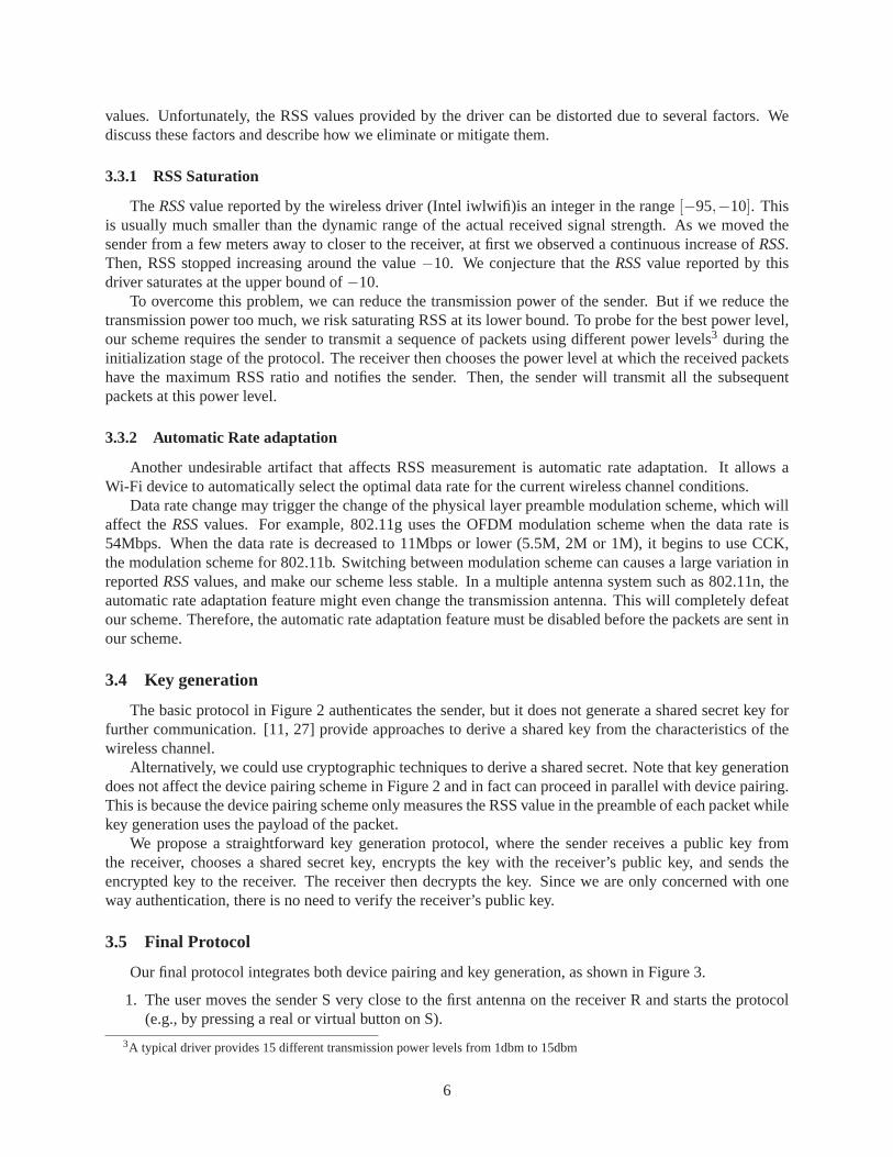
2. S→R: PairRequest(). S sends a pairing request to R.
3. R→S: PairResponse(KR). R responds with its public keyKR.
4. S→R: PowerQuery(i,n), wherei = 1, . . . ,n andn is the number of power levels. S sends a sequenceof packets from the lowest to the highest power levels.
5. R←S: PowerResponse(l). After receiving all then power query packets, R responds with the bestpower levell that maximizesr = RSS1−RSS2.
6. S→R: RSSMeasuring(EKR(k)). S generates a random session keyk and encrypts it with R’s public keyKR, and continually sends the copies of the encrypted session key to R at fixed interval. Meanwhile,the user moves the S from nearby the first antenna on R to nearby the second antenna on R.
7. R←S: Success(). R examines the RSS values of all packets (containing the encrypted session key)received at both its antennas. If R detects a sufficient number of consecutive packets whoser ’s meanis above a thresholdrH and whoser ’s standard deviation is below a thresholdδt , then R decides thatthe sender is nearby R’s first antenna. Similarly, R detects if the sender is then nearby R’s secondantenna. After R detects both these conditions, R replies with a success message.
Figure 3: Messages in the final protocol
The protocol runs above the MAC layer of the network stack. All messages exceptPowerQueryandRSSMeasureneed reliable transmission, i.e. a message needs to be repeated if it is lost.
4 Experiments and results
4.1 Setup
Our experimental system consists of a receiver and a sender, where the sender wishes to be paired withthe receiver.
7

Receiver The receiver is a Dell E5400 laptop running a modified Fedora Linux kernel version 2.6.29-rc5-wl based on the wireless-testing tree. The laptop has an integrated 802.11nIntel Wi-Fi Link 5300 wirelesscard, and is equipped with three internal antennas. We did not use any ofthe 802.11n-specific functions onthe card – all we needed is the ability to read the RSS values on each antenna individually. We modified thewireless device driver, the kernel-to-user space communication library (radiotap), and tcpdump to read theagcand RSSI values of each frame received by Antenna 1 and 2, respectively. RSS is computed as:
RSS= RSSI−agc−OFFSET
whereOFFSETis 44, a constant set by this Wi-Fi module, andagc(automatic gain control) is variable foreach packet.
Sender The sender is also a Dell E5400 laptop. Two of its antennas are disabled in the driver, and all thedata packets are sent via an external antenna connecting to it.
Antennas We conducted our experiments on the following four types of antennas. Inaddition to thebuild-in antenna on the laptop, we also used three types of external antennas, which can be connected to thebuilt-in Wi-Fi card via its IPX/U.fl connectors. Note that our scheme requiresno external antennas. Thereasons for using external antennas in this experiment are: (1) to measure the impact of the distance betweenthe two receiving antennas on the RSS ratio since we cannot vary the distance between the internal antennas;and (2) to evaluate whether our scheme works on different antennas.
• Type 1: These are the internal antennas in the Dell E5400 laptop. After disassembling the laptop, wefound that Antenna 1 is fixed at the top left of its LCD screen frame while Antenna 2 is at the top rightof the screen frame. We did not use Antenna 3.
• Type 2: These are Wi-Fi antennas for laptop mini PCI cards with 61cm (2 feet) IPX/U.fl cables.
• Type 3: These are 5 dBi omni-directional Wi-Fi antennas for access points. Each of them has aRP-SMA male interface. We connected them to the laptop using 60cm RPSMA female to IPX/U.flcables.
• Type 4: These are 60cm RP-SMA female to IPX/U.fl cables, which we used to connect Type 3antennas to the laptop. Here we used these cables directly as antennas. Wetried this type of antennabecause on some mobile devices, such as Openmoko freerunner smartphone, the antenna socket isused as a default antenna. Although they allow users to attach external antennas, few users do.
RSS measurement During all the following experiments, we measure RSS values as follows. First, wedisable all but one antenna on the sender, so that only one antenna is used to send all the packets. Weassociate the sender with the receiver in ad-hoc mode, i.e., packets travelfrom the sender to the receiverdirectly without going through a base station. Both the sender and the receiver are stationary. The packets areping packets with 10ms interval. To eliminate the Gaussian noise in the Log-normalshadowing model, wealways read RSS from 100 consecutive packets and calculate their mean. We conducted all the experimentsin an indoor environment (our lab).
4.2 Effect of distance on RSS
Based on Equation 3, the average RSS value should be a logarithmic functionof distanced between thesender and receiver antennas as follows:
RSS= P0−10αlog10(dd0
) (4)
8

whereP0 is the RSS value at unit distanced0.However, the Log-normal model usually applies whend is much larger than the size of the antennas. In
our scheme, when the sender is very close to the receiver,d could be as small as less than 1cm. So we wishto evaluate how well Equation 4 approximates RSS values whend is small.
During the evaluation, we tried to rule out other factors that may affect RSS. For instance, we alwaysaligned the sending and receiving antennas. We set the sender to use thelowest transmission powertx =1dBmand disabled the automatic rate adaptation feature. For antenna pairs 1, 2, and 4, we measured RSSvalues at various distances up to 10cm to avoid the multipath effect. However, since antenna pair 3 has amuch larger gain, their RSS is saturated when their distance is smaller than 2cm, so we measured their RSSat distances ranging from 2cm to 30cm. The result (Figure 4) shows thatthe logarithmic relationship inEquation 4 still approximates the measured RSS values vs distance where the path loss exponentα falls inthe range [1.057, 1.365].P0 is related with the gain of each antennas pair. It is measured as -11.15, -19.71,-3.59, and -43.21 for antenna pairs 1, 2, 3, 4 respectively.
Figure 4: Logarithmic relationship between RSS value and the sender-receiver distance
4.3 Antenna gains
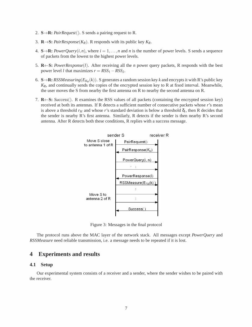
To show that the RSS ratio is independent of antenna gain, we read RSS values when the packets weresent with different transmission power. Our experimental results indicate that the RSS value is a linearfunction of the transmission power for different antenna distance:
RSS(d) = rss0(d)+ tx
wheretx is the transmission power of the sender measured in dBm andrss0(d) is the measured RSS valuewhen the sender uses the base transmission powertx= 0dBm. We can userss0(d) as a gain indicator of theantenna pair at distanced.
Figure 5 plots the RSS values when packets are sent at various transmissionpower for each antenna pair.The distance between the sender and receiver was fixed at 10cm. A very small distance tends to cause RSSvalues to saturate when the transmission power increases, while a very large distance could introduce moreinterference from the environment, such as the multipath effect (Section 6.1.2). The figure also shows thatthe gains of the four antennas pairs are ordered asType3 > Type1 > Type2 > Type4. This is consistentwith the order ofP0 values measured in the experiment in Section 4.2.
9
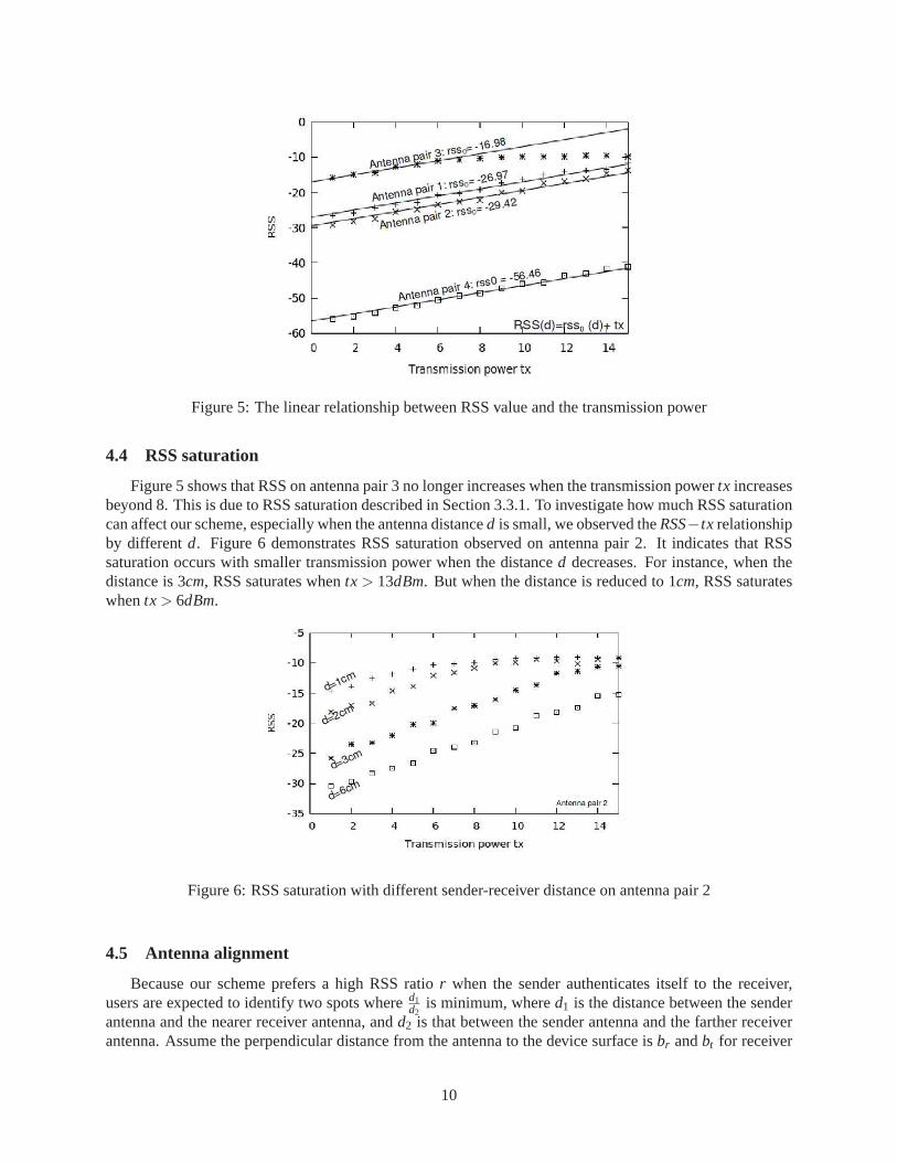
Figure 5: The linear relationship between RSS value and the transmission power
4.4 RSS saturation
Figure 5 shows that RSS on antenna pair 3 no longer increases when the transmission powertx increasesbeyond 8. This is due to RSS saturation described in Section 3.3.1. To investigate how much RSS saturationcan affect our scheme, especially when the antenna distanced is small, we observed theRSS−tx relationshipby differentd. Figure 6 demonstrates RSS saturation observed on antenna pair 2. It indicates that RSSsaturation occurs with smaller transmission power when the distanced decreases. For instance, when thedistance is 3cm, RSS saturates whentx> 13dBm. But when the distance is reduced to 1cm, RSS saturateswhentx> 6dBm.
Figure 6: RSS saturation with different sender-receiver distance on antenna pair 2
4.5 Antenna alignment
Because our scheme prefers a high RSS ratior when the sender authenticates itself to the receiver,users are expected to identify two spots whered1
d2is minimum, whered1 is the distance between the sender
antenna and the nearer receiver antenna, andd2 is that between the sender antenna and the farther receiverantenna. Assume the perpendicular distance from the antenna to the devicesurface isbr andbt for receiver
10

and sender, respectively, the minimumd1 is br +bt . We called the sender and the receiver arealignedin thiscase. In reality, the user may not be able to align the sender with the receiver perfectly. This misalignmentwould adversely affect RSS because it increases the distance betweenthe sending and receiving antennasand thus decreases the RSS value. Letx be the distance between the current location of the sender andits ideal aligned location with thedominantantenna (the antenna on the receiver that the sender should bealigned with), the theoretical RSS value read from the dominant antenna should be:
RSS= P0−10αlog10
√d2+x2
d0
We evaluated how much our scheme tolerates the misalignment between the sender and the dominantreceiving antenna. We conducted experiments using antenna pair 2 and 4. We setd to be 2cm and measuredRSS at differentx.
Figure 7: The relation between the RSS value and the offset
Figure 7 shows that RSS value is insensitive to misalignment when the misalignmentis small (< 1cm),but the effect becomes noticeable when the misalignment increases. To avoid large misalignment, the de-vices could mark the location of their antennas on their surfaces. Moreover, when we select the thresholdsrL andrH in the device pairing protocol in Section 3.2, we need to take into account howmuch we tolerateantenna misalignment.
4.6 Distance between the receiving antennas
To take advantage of the antenna diversity [15], most laptops have their antennas mounted on the cornersof their LCD frames or the two sides of their bodies. Therefore, the receiving antennas are usually more than20cm away from each other. However, handheld mobile devices have much smaller sizes. Even though ourscheme requires only the receiver to have two antennas, will our scheme be applicable to handheld mobiledevices that have multiple antennas and that are used as the receiver?
To answer the above question, we conducted the following experiment. We used a Dell E5400 laptopconnected with two external antennas (Type 2) as the receiver. We chose an Openmoko Freerunner smart-phone as the sender and placed it only 1cm away from one of the two external antennas on the receiver.Similar to all the previous experiments, the sender phone established an ad hoc connection with the receiverand continually sent ping packets with an interval of 10ms. The transmission power was tuned in advance toavoid RSS saturation. We measured the RSS ratios of 100 consecutive packets when the sender was alignedwith the left receiving antenna and right receiving antenna, respectively. We repeated this measurement for
11

L (cm) RSS on Antenna 1 RSS on Antenna 2r δ r δ
10 13.72 0.86 -13.77 0.4220 14.69 0.46 -16.90 0.4430 20.49 0.52 -18.04 0.31
Table 1: Measured RSS ratios under various distance between two receiving antennas.L is the distancebetween two receiving antennas.
different distances between the two external antennas on the receiver: 10cm, 20cm, and 30cm. Table 1shows the mean and standard deviation of the RSS.
The experiment indicates that even when the distance between the two receiving antennas decreases to10cm, which is a reasonable lower bound on most handheld devices, the RSS ratio is still large enough(13.72) to be usable in our scheme.
5 Prototype
We developed a prototype of our device pairing scheme to evaluate its security and usability.
5.1 Set up
Sender The sender is an Openmoko Free Runner smartphone running Linux. It has a single antenna anda Wi-Fi module.
Receiver The receiver is a Dell E5400 laptop running a modified Fedora Linux kernel version 2.6.29-rc5-wl based on the wireless-testing tree. The laptop has an integrated 802.11nIntel Wi-Fi Link 5300 wirelesscard, and is equipped with three internal antennas, although our prototype uses only two of these antennas.We marked the locations of the antennas on the surface of the laptop.
Pairing procedure The sender and receiver share no prior secret. The receiver continuously runs a pairingserver program. The user pairs the sender with the receiver via the following steps:
1. The user places the sender next to the left antenna of the receiver.
2. The user starts our pairing program on the sender. Then, the program sends a sequence of packets tothe receiver.
3. After receiving a sufficient number of measurement packets that satisfy the pairing criteria below(usually within a few seconds), the receiver notifies the user via a beep.Then, the user places thesender next to the right antenna of the receiver.
4. After receiving another sufficient number of measurement packets that satisfy the pairing criteria , thereceiver notifies the user of a successful pairing via multiple beeps.
Pairing criteria The receiver decides whether the sender is close by measuring the RSS ratios (i.e., theratio between the RSS on the left and right antennas) of the RSSIQuery packets from the sender. In bothStep 3 and 4 above, the receiver places the packets into a FIFO queue ofsize 40 and checks if the RSS ratiosof all the packets in the queue satisfy:
• The mean ¯r of the RSS ratios exceeds a threshold (¯r > rH in Step 3, and ¯r < rL in Step 4).
12

Distance range < 20cm [20cm,100cm] > 100cm
Success Rage 90% 0% 0%Failure Rate 10% 100% 100%
Max Mean RSS Ratio 15.62 6.35 3.43
Table 2: Authentication Accuracy. Authentication in each distance range is tried 20 times.
• The standard deviation of the RSS ratios is smaller than a thresholdδt .
The sender sends about 40 packets per second. To be robust against signal interference, the receiver keepscomputing the above pairing criteria (i.e., whenever a new packet arrives, it is inserted into the FIFO queueof 40 packets, and the receiver reruns the pairing criteria on the queue) for 20 seconds until the pairingsucceeds or the receiver times out.
In the above criteria,rH andrL depend on the distanced between the two antennas on the receiver. In ourprototype system,d = 26cm. Based on our experiment in Section 4.2, the RSS ratio from a nearby sendershould be larger than 16. We setrH = 11 andrL =−11 to leave some room for antenna misalignment. Wesetδt = 0.6 based on our observations.
5.2 Security evaluation
We evaluated the security of our prototype by trying to authenticate the sender at different distancesfrom the receiver:
1. Close-range: The sender is placed next to the receiver, e.g., whenthe user places the Openmoko phonenext to the screen of the laptop where an antenna is located.
2. Mid-range: The sender is between 20 – 100cm away from the receiver.
3. Long-range: The sender is more than 100cm away from the receiver.
We believe that 100cm is a reasonable estimate of the minimum distance that the attacker can place herdevice wherever without alarming the receiver owner. However, we also conducted our evaluation with amore conservative estimate of the minimum distance, 20cm. For each distance range, we attempted devicepairing 20 times. In the experiments for mid-range and long-range, at eachdevice pairing attempt werandomly placed the sender within that range.
Table 2 shows that the success rate for close-range (< 20cm) device pairing is 90%. The two failedpairings in this range happened when we failed to align the sender’s antenna with that of the receiver. Bycontrast, our prototype rejected all the device pairing attempts when the sender was in either mid-range([20cm,100cm]) or long-range (> 100cm). Table 2 also shows the maximum mean RSS ratios of the packetsin different distance ranges. When the sender is in close-range, the maximum mean RSS ratio is above 15,while this ratio drops to 6.35 and 3.43 when the sender is in mid-range and long-range, respectively.
5.3 Usability evaluation
We measured the time that it takes the user to complete a successful device pairing. From the user’sperspective, the pairing consists of three steps:
0. Move the sender to the left antenna of the receiver.
1. Click a button on the sender to start the pairing, and wait for the receiver to beep (indicating that thereceiver has received enough measurement packets that satisfy its criteria).
13

2. Move the sender to the right antenna of the receiver, and wait for thereceiver to beep multiple times(indicating that the pairing has succeeded).
We did not measure the time for Step 0 because it is irrelevant to the design of our protocol. We measuredthe time for Steps 1 and 2 shown in Table 3.
Distance range < 20cm [20cm,100cm] > 100cm
Time for Step 1Average 5.29s 6.53s Timeout
Minimum 5.06s 5.33s TimeoutMaximum 5.52s 7.72s TImeout
Time for Step 2Average 6.35s Timeout Timeout
Minimum 2.77s Timeout TimeoutMaximum 17.59s Timeout TImeout
Total Time Average 11.64s Timeout Timeout
Table 3: Authentication Time.
The user took an average of 5.29s to complete Step 1. A large portion of this time(3.67s) is spent onwaiting for the sender to send 15 power query packets. Currently, to send a packet at a different power level,our prototype implementation in the sender needs to execute theiwconfig command, which takes about200ms each time. To reduce the time spent on Step 1, we could use more efficient ways to adjust the powerlevels of packets, or to find the best power level more efficiently than a linear search (e.g., a binary searchbetween all the power levels). The user took an average of 6.35s to complete Step 2. Compared to Step 1,the variation in the time for Step 2 is larger because it includes the time for the userto move the senderfrom the left antenna to the right antenna of the receiver. The averagetotal time for the pairing is 11.64s.This is faster than or comparable to most other wireless device pairing schemes[9]. Moreover, this schemerequires no user decision and has a fail-safe default: if the user fails to follow the simple procedure, thepairing simply fails.
6 Security and usability
6.1 Security
6.1.1 Probability of success of random attacks
We calculate the probability of successful attack if a faraway attacker justrandomly picks two loca-tions during the device pairing. Assume RSS ratior induced by the attacker follows Gaussian distributions
N(µH ,σ2H) andN(µL,σ2
L), the means ofn RSS ratioµH andµL should followN(µH ,σ2
Hn ) andN(µL,
σ2L
n ), re-
spectively. The sample variancesσ2H andσ2
L have distributions proportional to chi-square asσ2Hn ·χ2(n−1)
and σ2L
n ·χ2(n−1), respectively.Let the threshold of the mean asµt and that of the variance asσ2
t , the attacker’s device will be pairedonly whenµH is larger than its threshold and ˆµL is smaller than its threshold, and the sample variancesσ2
Hand σ2
L are smaller than their threshold. Note that for normal distribution, the sample mean and samplevariance are independent. Therefore, ˆµH , σ2
H , µL, andσ2L are independent of each other. The probability of
a successful attack is:
Pa = Pr(µH > µt) ·Pr(−µL > µt) ·Pr(σ2H < σ2
t ) ·Pr(σ2L < σ2
t )= Q( µt−µH
σH/√
n) · (1−Q(−µt−µLσL/√
n ))
· γ((n−1)/2,(nσ2t )/(2σ2
H))Γ((n−1)/2) · γ((n−1)/2,(nσ2
t )/(2σ2L))
Γ((n−1)/2)
(5)
14

whereQ(x) is the Q-function computing the right-tail probability for normal random variables,γ(k,x) is thelower incomplete Gamma function, andΓ(k) is the Gamma function.
Using the parameters set for our prototype system, the probability of successful attack is less than10−15.4
6.1.2 Attacks leveraging multipath effects
In our experiments on the prototype system, the Openmoko smartphone survived the first phase of thedevice pairing for 4 times in 20 when it was at least 20cm away from either antenna on the laptop. Itindicates that the laptop has a relatively high possibility to receive a sufficient number of packets that havestable and large RSS ratio even when the sender is not in its close proximity. This is inconsistent with theabove calculation of false positive rate. To explain it, we have to look at the other factors that affect RSSvalue. Multipath effects is the most significant factor.
As the result of multipath effect, the received signal can become strongeror weaker if there is a con-structive or destructive superposition of the signals coming from different paths, respectively. In an indoorenvironment, multipath effect is often caused by reflection on the surface of the floor, ceiling, wall, furniture,and even people. Using our scheme, when the sender is paired with a nearby receiver, the multipath effectwill unlikely affect the RSS values significantly because the sender is veryclose to the receiver. However, afaraway attacker could take advantage of the multipath effect to cause a large RSS ratio measured at the twoantennas on the receiver, therefore breaking our scheme.
Figure 8: Two paths model
We use the following simplified two-path model to show how much multi-path effect can affect ourscheme. Assume the signal strength is determined by only two dominating paths: astraight path from thesender to the receiver, and a path reflected on the ground, as shown inFigure 8. LetHS be the heightof the sending antenna,HR be the height of the two receiving antennas,L be the distance between tworeceiving antennas,LD1 andLD2 be the length of two direct paths, andLR1 andLR2 be the length of tworeflect paths. We also defineΓ as the reflection coefficient, which depends on the polarization of the radiowave. According to [24], we have:
r = 10log10(LR1 ·cos∆θ1+ΓLD1)
2+(LR1 ·sin∆θ1)2
(LR2 ·cos∆θ2+ΓLD2)2+(LR2 ·sin∆θ2)2
4We compute the probability in Matlab, which gives answer 0. Since Matlab supports 10−15 precision, we conclude that theprobability is less than 10−15.
15
where∆θ1 and∆θ2 are phase delays, which are determined byLR1, LD1 andLR2, LD2 respectively. Clearly,attacker can choose appropriate path lengths to maker a large value.
We can mitigate this attack by incorporating frequency hopping into our protocol. With frequencyhopping, the attacker’s optimal path lengths in different channels are likelydifferent, so it would be verydifficult to find a path length that keeps the RSS ratio high in all the channels. Incorporating frequencyhopping in our scheme is straightforward: instead of using only one channel, S sendsRSSIMeasuringpacketswhile cycling through all the channels. However, it is not easy to implement frequency hopping on theplatform where we implemented our prototype, because it takes substantial timeto switch wireless channelsfrom the user space. We believe that this limitation can be overcome by an implementation of frequencyhopping in the device driver or the firmware.
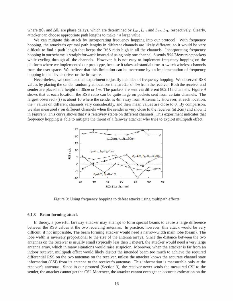
Nevertheless, we conducted an experiment to justify this idea of frequency hopping. We observed RSSvalues by placing the sender randomly at locations that are 2mor 4m from the receiver. Both the receiver andsender are placed at a height of 30cmor 1m. The packets are sent via different 802.11a channels. Figure 9shows that at each location, the RSS ratio can be quite large on packets sent from certain channels. Thelargest observedr(t) is about 10 where the sender is 4m away from Antenna 1. However, at each location,the r values on different channels vary considerably, and their mean valuesare close to 0. By comparison,we also measuredr on different channels when the sender is very close to the receiver (at 2cm) and show itin Figure 9. This curve shows thatr is relatively stable on different channels. This experiment indicates thatfrequency hopping is able to mitigate the threat of a faraway attacker who tries to exploit multipath effect.
Figure 9: Using frequency hopping to defeat attacks using multipath effects
6.1.3 Beam-forming attack
In theory, a powerful faraway attacker may attempt to form special beamsto cause a large differencebetween the RSS values at the two receiving antennas. In practice, however, this attack would be verydifficult, if not impossible, The beam forming attacker would need a narrow-width main lobe (beam). Thelobe width is inversely proportional to the size of the antenna arrays. Sincethe distance between the twoantennas on the receiver is usually small (typically less then 1 meter), the attacker would need a very largeantenna array, which in many situations would raise suspicion. Moreover,when the attacker is far from anindoor receiver, multipath effect would likely distort the intended beam too much to achieve the requireddifferential RSS on the two antennas on the receiver, unless the attackerknows the accurate channel stateinformation (CSI) from its antenna to the receiver’s antennas. This information is measurable only at thereceiver’s antennas. Since in our protocol (Section 3), the receiver never sends the measured CSI to thesender, the attacker cannot get the CSI. Moreover, the attacker cannot even get an accurate estimation on the
16
CSI based on its observation of the reverse channel (the channel from the receiver to the attacker) becauseof the following two reasons. First, our protocol does not require the receiver to send messages via both itsantennas. Therefore, the attacker cannot measure the reverse CSI of both the channels. Second, even if thereceiver sends signals from both its antennas, the CSI of the reverse channel may be different from that ofthe forward one because reciprocity may not hold due to non-symmetric noise.
6.1.4 Time-of-check to time-of-use attack
Since RSS is measured in the physical layer preamble while the session key is carried in the frame, anattacker might try to attack Step 4 in the protocol described in Section 3.5 by sending his encrypted sessionkey when the receiver begins to receive the frame. However, this attackis nearly impossible. First, it isvery hard for the attacker to time his frame at the moment just after the receiver has received the preamblefrom another user. For 802.11a and 802.11g, a symbol lasts 4 microseconds, including an 800 nanosecondguard interval. If the attacker wants his first symbol to arrive at the receiver just after the genuine sender’spreamble, she must be able to control his transmission delay within one microsecond. However, it is nearlyimpossible to control the transmission delay in such fine granularity. Even if theattacker could achieve this,his frame would collide with the genuine sender’s frame, which would cause the receiver to drop the frame.Although the attacker can launch an DoS attack this way, he could launch DoSmore easily by jamming,which is out of the scope of this work.
6.2 Usability
Resilience against interference One advantage of our scheme is its ability to resist interference. Manydevice pairing schemes require the use of auxiliary “out-of-band” channels, such as acoustic [16], thatare subject to environment interference. By contrast, our scheme usesauxiliary information (RSS) in theexisting wireless channel. Therefore, it inherits the interference-resistance properties from the wirelesschannel. All our experiments were conducted in a typical computer sciencebuilding with several APs andmicrowave ovens.
Avoiding user errors Our scheme requires no decision from the user. All the user has to do is to move thesender from one place to another. Therefore, the user’s device cannot be erroneously paired with a deviceheld by a faraway attacker.
Ease of use The relatively challenging part of our scheme for the user is to align the antennas of twodevices; failure to align may result in device pairing failure. Similar efforts are required by other devicepairing schemes. [13], for instance, requires the user to align the cameraof one device to the screen of theother. In [16], users have to move one device along the direction of the other one. Both the above schemesrequire users to move one device in a 3D space. By contrast, our scheme only requires the user to move thesender in the 2D surface of the receiver. When the locations of the antennas are marked on the surface ofthe receiver, this becomes a simple task.
Pairing time The experiments showed that it takes an average of 11.64s to pair the devices in our pro-totype, which is faster than most schemes tested by [9]. Although we (the authors) conducted the tasksourselves in our experiments, we expect to observe a similar pairing time on ordinary users because ourscheme requires a simple movement and no user decision.
Versatility Our scheme requires the receiver to have two antennas separated by a reasonable distance. Forexample, when a user pairs a smartphone with his laptop, only the laptop needstwo antennas. Fortunately,
17

most current laptops, including the ones without 802.11n modules, use multipleantennas to take advantageof antenna diversity [15].
Additionally, there is an obvious trends towards embedding 802.11n Wi-Fi in handheld mobile devices(at least the chip manufacturers are ready [21]). When this becomes popular, our scheme can pair twohandheld mobile devices as well.
7 Related work
Wireless device paring With the proliferation of mobile wireless devices, researchers have proposedmany schemes for secure devices pairing. These schemes rely on trustedside-channels to pair the deviceswith each other. Earlier approaches required the user to be the channel,i.e., they asked the user to enter theshared secret into the devices, but these methods suffer from apparent usability and security problems dis-cussed in the introduction. To avoid these problems, researchers have since proposed newer schemes to usethe extra sensory and output hardware present on many wireless devices as the trusted communication chan-nel [9]. We can divide these schemes into two categories in terms of user interaction: (1) those that requirethe user to decide whether the device pairing succeeds by comparing visual [25] or audio [5, 22] output; (2)those that require the user to initiate the device pairing but let the device decide whether the pairing succeedsvia the reading from its sensors (e.g., a camera [13, 20], microphone [17, 19], or accelerometer [7, 12]). Ourproposed mechanism falls into the latter group, which has the advantage thatit is less fallible to user errorssince users do not need to decide the success of the authentication. However, while most wireless deviceshave some sensory or output hardware, two arbitrary devices may not have the required hardware to providesecure authentication. For example, [13, 20] applies only to devices with cameras. By contrast, our schemeuses the primary communication channel of wireless devices for authentication and thus requires no extrahardware. Although our scheme requires the receiver to have at leasttwo antennas, multiple antennas areincreasingly common as wireless device manufacturers are embracing the MIMO (Multiple-Input Multiple-Output) technology. (Note that our scheme does not require the sender tohave more than one antenna.)
Distance bounding protocols Distance bounding protocols [3] are cryptographic protocols that establishan upper-bound on the physical distance between two parties by timing the delay between sending out achallenge bit and receiving the response bit. They have been implemented for various wireless protocols [26,6], but all of them rely on a rapid bit exchange and require precise clocks to measure the delay betweenmessages traveling at the speed of light. Since electromagnetic waves propagate over 30cm in 1 nanosecond,the requirement for such high precision clocks is unsuitable for consumerelectronic devices.
Our scheme can reliably determine the proximity of the pairing devices without requiring high-precisionclocks; instead, our scheme measures the ratio between the receiving signal strength at multiple antennas.
Received signal strength Researchers have used Received signal strength (RSS) to detect thesybil attackin wireless sensor networks [4], where they used the RSS ratio between different monitors to locate users.There are many differences between our scheme and theirs, the biggestone being the purpose: our scheme isfor deciding whether the sender is close to the receiver, while their schemeis for deciding if the packets withdifferent identities come from the same location. As a result, our scheme enjoys the following advantages.(1) Our scheme needs only two antennas, while in theory their scheme requires at least four to achieve anaccurate localization. (2) The precision of their scheme is in meters, while ourscheme can reject attackersthat are merely 20cm away. On the other hand, our scheme also has to overcome extra challenges: sincethe user has to hold and move the sender during device pairing and the sender is very close to the receiver,our scheme is more susceptible to radio signal interference and variation. We used statistics and powerlevel probing to overcome this problem. Finally, since our goal is device pairing, we also need to design aprotocol that derive a shared secret.
18

Hu and Evans use directional antennas to verify proximity to prevent wormhole attacks [8]. By contrast,our scheme does not require directional antennas. In fact, our schemeprefers omnidirectional antennas be-cause they avoid the problem of misalignment between the sending and receiving antennas. Most consumerwireless devices also prefer omnidirectional antennas because the users would not have to orient the devicesin certain directions.
8 Conclusion
We have designed a reliable secure device pairing scheme based on device proximity. The scheme takesadvantage of multiple antennas built in many modern wireless devices and leverages a characteristic of wire-less channels - the power of the received signal is inversely proportional to some exponent of the distancebetween the sender and receiver. When a nearby sender is very close to one antenna on the receiver, thereceiver can observe a large difference between the power measured on its two antennas, whereas a farawaysender would be unable to induce this large difference. We validated our scheme through theoretical analysisand experimental measurements. We discussed factors that may affect our scheme, including antenna gain,antenna alignment, RSS saturation, dynamic rate adaptation and multipath effects. Finally, we evaluated aprototype of our scheme by pairing an Openmoko Free Runner mobile phonewith a laptop using thresholdvalues derived from our measurements. The experiment shows that ourscheme is easy, fast, and reliable.
References
[1] Eye-Fi SD card wiki page.http://en.wikipedia.org/wiki/Eye-Fi.
[2] Wi-Fi protected setup.http://en.wikipedia.org/wiki/Wi-Fi_Protected_Setup.
[3] Stefan Brands and David Chaum. Distance-bounding protocols. InEUROCRYPT ’93: Workshop on the theoryand application of cryptographic techniques on Advances incryptology, pages 344–359, Secaucus, NJ, USA,1994. Springer-Verlag New York, Inc.
[4] Murat Demirbas and Youngwhan Song. An rssi-based schemefor sybil attack detection in wireless sensornetworks. InWOWMOM ’06: Proceedings of the 2006 International Symposium on on World of Wireless,Mobile and Multimedia Networks, pages 564–570, Washington, DC, USA, 2006.
[5] Michael T. Goodrich, Michael Sirivianos, John Solis, Gene Tsudik, and Ersin Uzun. Loud and clear: Human-verifiable authentication based on audio. InICDCS ’06: Proceedings of the 26th IEEE International Conferenceon Distributed Computing Systems, page 10, Washington, DC, USA, 2006. IEEE Computer Society.
[6] G.P. Hancke and M.G. Kuhn. An rfid distance bounding protocol. In Security and Privacy for Emerging Areasin Communications Networks, 2005. First International Conference on, pages 67–73, Sept. 2005.
[7] Lars Erik Holmquist, Friedemann Mattern, Bernt Schiele, Petteri Alahuhta, Michael Beigl, and Hans-WernerGellersen. Smart-its friends: A technique for users to easily establish connections between smart artefacts.In UbiComp ’01: Proceedings of the 3rd international conference on Ubiquitous Computing, pages 116–122,London, UK, 2001.
[8] Lingxuan Hu and David Evans. Using directional antennasto prevent wormhole attacks. InNetwork andDistributed System Security Symposium (NDSS), San Diego, CA, February 2004.
[9] Alfred Kobsa, Rahim Sonawalla, Gene Tsudik, Ersin Uzun,and Yang Wang. Serial hook-ups: a comparativeusability study of secure device pairing methods. InSOUPS ’09: Proceedings of the 5th Symposium on UsablePrivacy and Security, pages 1–12, New York, NY, USA, 2009. ACM.
[10] John Krumm and Eric Horvitz. Locadio: Inferring motionand location from Wi-Fi signal strengths. Inin FirstAnnual International Conference on Mobile and Ubiquitous Systems: Networking and Services (Mobiquitous,2004.
19

[11] Suhas Mathur, Wade Trappe, Narayan Mandayam, ChunxuanYe, and Alex Reznik. Radio-telepathy: extract-ing a secret key from an unauthenticated wireless channel. In MobiCom ’08: Proceedings of the 14th ACMinternational conference on Mobile computing and networking, pages 128–139. ACM, 2008.
[12] Rene Mayrhofer and Hans Gellersen. Shake well before use: Intuitive and secure pairing of mobile devices.IEEE Transactions on Mobile Computing, 8(6):792–806, 2009.
[13] J.M. McCune, A. Perrig, and M.K. Reiter. Seeing-is-believing: using camera phones for human-verifiableauthentication. InSecurity and Privacy, 2005 IEEE Symposium on, pages 110–124, May 2005.
[14] Aleksandar Neskovic, Natasa Neskovic, and George Paunovic. Modern approaches in modeling of mobile radiosystems propagation environment.IEEE Communications Surveys, 3(3):1–12, 2000.
[15] Bob O’Hara and Al Petrick.The IEEE 802.11 Handbook: A Designer’s Companion. Standards InformationNetwork IEEE Press, 1999.
[16] Chunyi Peng, Guobin Shen, Yongguang Zhang, Yanlin Li, and Kun Tan. Beepbeep: a high accuracy acousticranging system using cots mobile devices. InSenSys ’07: Proceedings of the 5th international conference onEmbedded networked sensor systems, pages 1–14, New York, NY, USA, 2007. ACM.
[17] Chunyi Peng, Guobin Shen, Yongguang Zhang, and Songwu Lu. Point&connect: intention-based devicepairing for mobile phone users. InMobiSys ’09: Proceedings of the 7th international conference on Mobilesystems, applications, and services, pages 137–150, New York, NY, USA, 2009. ACM.
[18] Theodore S. Rappaport.Wireless Communications: Principles and Practice. Prentice Hall, New Jersey, 2001.
[19] Kasper Bonne Rasmussen, Claude Castelluccia, Thomas S. Heydt-Benjamin, and Srdjan Capkun. Proximity-based access control for implantable medical devices. InCCS ’09: Proceedings of the 16th ACM conference onComputer and communications security, pages 410–419, New York, NY, USA, 2009. ACM.
[20] Nitesh Saxena, Jan-Erik Ekberg, Kari Kostiainen, and N. Asokan. Secure device pairing based on a visualchannel (short paper). InSP ’06: Proceedings of the 2006 IEEE Symposium on Security and Privacy, pages306–313, Washington, DC, USA, 2006. IEEE Computer Society.
[21] Anton Shilov. Mobile phones with faster 802.11n Wi-Fi incoming. http://www.xbitlabs.com/news/networking/display/20091110182814_Mobile_Phones_with_Faster_802_11n_Wi_Fi_Incoming_Research_Firm.html, December 2009.
[22] Claudio Soriente, Gene Tsudik, and Ersin Uzun. Hapadep: Human-assisted pure audio device pairing. InISC ’08: Proceedings of the 11th international conference on Information Security, pages 385–400, Berlin,Heidelberg, 2008.
[23] Frank Stajano and Ross Anderson. The resurrecting duckling: Security issues for ubiquitous computing (supple-ment to computer magazine).Computer, 35:22–26, 2002.
[24] Tsenka Stoyanova, Fotis Kerasiotis, Aggeliki Prayati, and George Papadopoulos. Evaluation of impact fac-tors on rss accuracy for localization and tracking applications. InMobiWac ’07: Proceedings of the 5th ACMinternational workshop on Mobility management and wireless access, pages 9–16, New York, NY, USA, 2007.
[25] Serge Vaudenay. Secure communications over insecure channels based on short authenticated strings. InAd-vances in Cryptology - CRYPTO 2005: 25th Annual International Cryptology Conference, volume 3621 ofLecture Notes in Computer Science, pages 309–326, 2005.
[26] SrdjanCapkun, Levente Buttyan, and Jean-Pierre Hubaux. Sector: secure tracking of nodeencounters in multi-hop wireless networks. InSASN ’03: Proceedings of the 1st ACM workshop on Security of ad hoc and sensornetworks, pages 21–32, New York, NY, USA, 2003. ACM.
[27] K. Zeng, D. Wu, A. Chan, and P. Mohapatra. Exploiting multiple-antenna diversity for shared secret key gener-ation in wireless networks. InIEEE Infocom 2010, March 2010.
20