gong jiayi 699151 partb
DESCRIPTION
Part BTRANSCRIPT


1. 21.
3
PART.BCRITERIA DESIGN
B.1 RESEARCH FIELD
STRUCTURE
One of the research field I found interesting is the Structure. As structure involves intersections, tension and compression, it is possible to achieve with the help from drones. Some of the precedents in Part A relating to structure are the Bird Nest and the roof of the Smithsonian institute. To narrow my field, I will be focusing on the Structure system in the Lunchbox plug-in. It forms average trusses and lattice within a defined surface. In testing various shapes and radius, patterns and waffles can be achieved in computational structural design as well. Focusing on structure might shift a bit away from traditional building design, but meanwhile, it opens more opportunities on engineering structures. Shelters, bridges, and towers are some possibilities that worth a try. The concerns for fabricating a structural design might range from material performance to load bearing capability. Simulations for tension and compression are vital, therefore testing different phases in Kangaroo Physics will be helpful to develop a more optimized result.
HERZOG DEMURON - BIRDS NEST
STUDIO GANG - SOUTH POND
IBA ARCHITECTS - CANTON TOWER
1. 41.
5
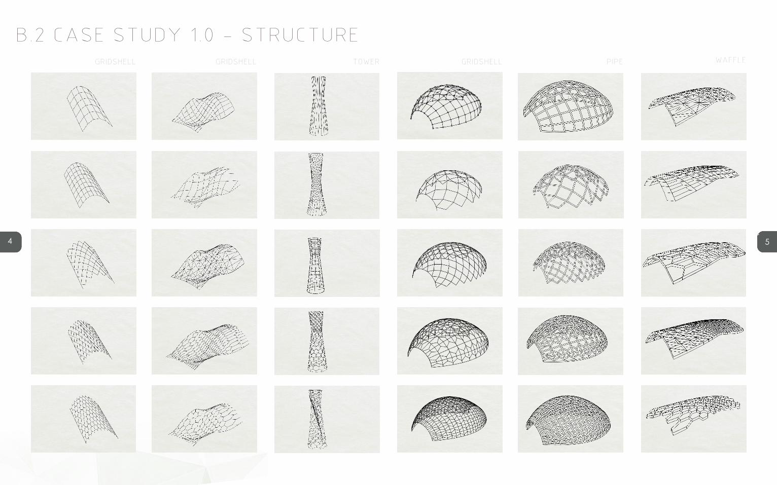
B.2 CASE STUDY 1.0 - STRUCTUREGRIDSHELL GRIDSHELL TOWER GRIDSHELL PIPE WAFFLE
1. 61.
7
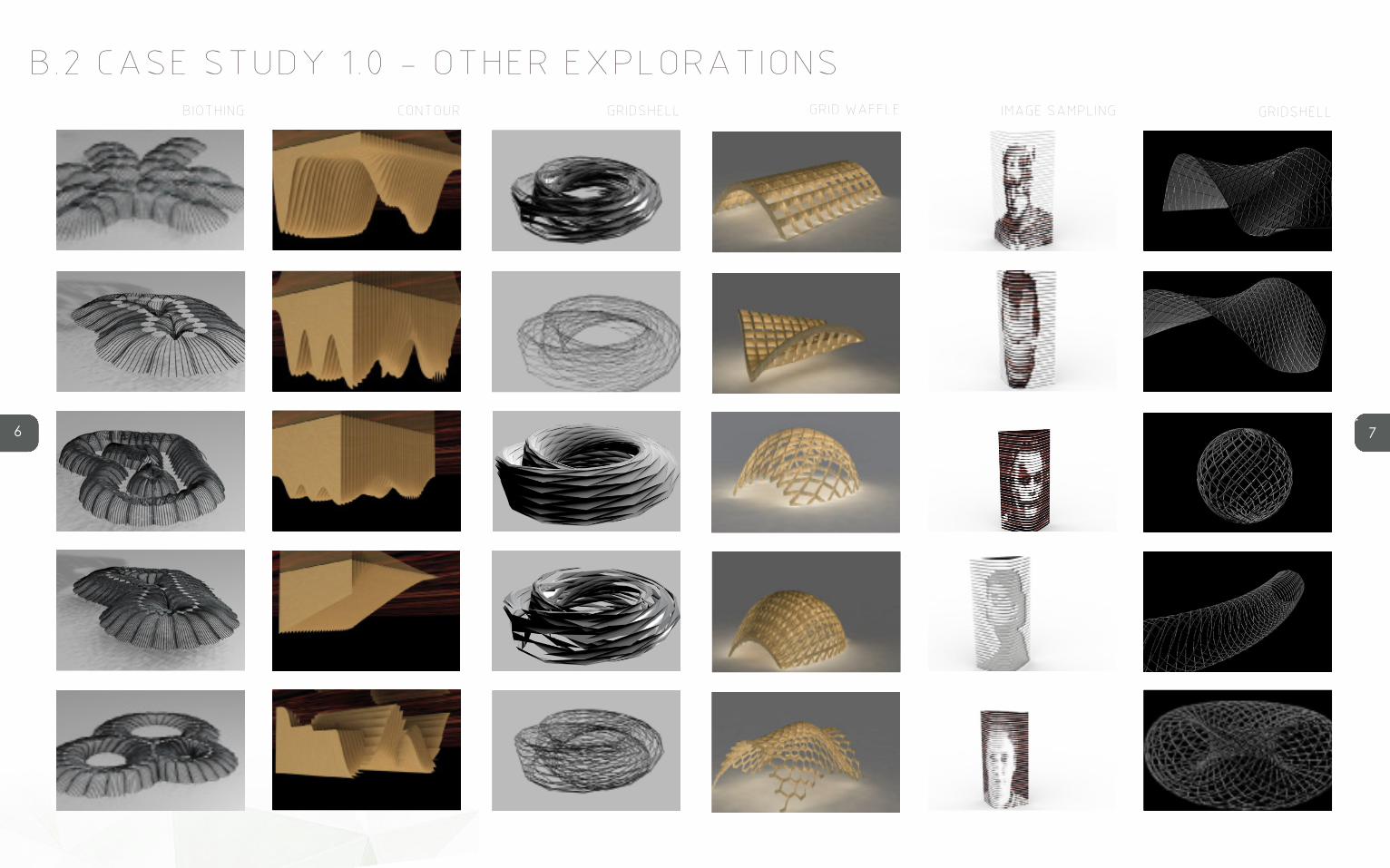
B.2 CASE STUDY 1.0 - OTHER EXPLORATIONSBIOTHING CONTOUR GRIDSHELL GRIDSHELLIMAGE SAMPLINGGRID WAFFLE

1. 81.
9
SELECTION CRITERIA
My selection criteria will be corresponding to the brief of building with drones. The outcomes that I am satisfied with should be applicable with strechting cable construction and rely on tension force as much as possible. Interesting patterns should be formed through drone technologies such as knotting and weaving.
The first outcome is barrel vault structure with a relatively dense diagonal grid. Through changing the parameter of the number of rows and columns, I found that the denser the grid is, the tighter the cables are. Tension force is what I want to achieve in a drone-built structure therefore this one meets my expectation. The second grid is formed with a combination of perpendicular and diagonal lines, which make the cable structure look similar to a panel structure. This outcome inspired me a possibility in applying panels to cable beam structures for future development.
The third one, a tower constructed from inclined cables, is the one I found most interesting and applicable in a structure based on tension force. Stretching the cables into different degrees of inclination creates an illusion of a twisted tower.
The fourth dome structure is formed by the combination of perpendicular and hexagonal gird. The parameter for rows and columns were set different for two components therefore it formed a new pattern which looks like a knitting design.
SPECULATE
Stretching cables through tension force opens a new possibility for building a tower structure. Or further it can be applied to a tower in a suspension bridge structure because tension force allows a wide span over cross a large area. In grasshopper definition, the bottom of cables can be extended to two or more directions to hold a bridge panel. Patterns formed through weaving have a more soft characteristic therefore I would consider not to count them as part of structure but a decorative or directive ones. They can go around the cables with tension force, and through changing density or shape to create different emotions.

1. 101.
11
B.3 CASE STUDY 2.0 - CANTON TOWER
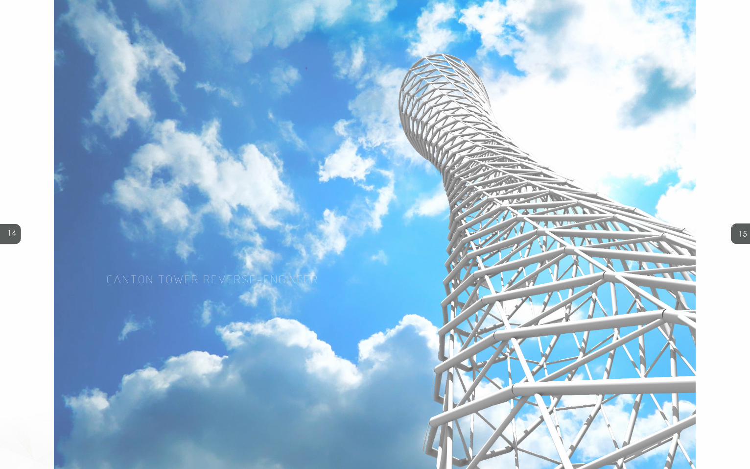
To explore the filed on structure, I chose Canton Tower for a case study. Canton Tower is designed by Information Based Architecture (IBA) , a Dutch architecture firm based in Amsterdam. The concept of the tower consists of a simple idea of a twisted tower. The form, volume and structure of the towers is generated by two ellipses, one at foundation level and the other at a horizontal plane at 450 m. These two ellipses are rotated relative to another. The tightening caused by the rotation between the two ellipses forms a "waist" and a densification of material halfway up the tower. This means that the lattice structure, which at the bottom of the tower is porous and spacious, becomes denser at waist level. The waist itself becomes tight, like a twisted rope. Further up the tower the lattice opens again. [1]Columns rings and diagonals form together a web that varies over the section of the tower. The columns are all perfectly straight although the lean over to one direction, giving the tower a dynamic twist.In this section, I will try to reverse-engineer the structure of Canton Tower using Grasshopper, and explore how a hyperboloid structure can be applied to my design.
1. China Highlights, Canton Tower, retrieved April 2016 from http://www.chinahighlights.com/guangzhou/attraction/canton-tower.htm
INCLINED ELLIPSE
FOUNDATION ELLIPSE
WAIST
RINGS
STRAIGHT COLUMNS
DIAGONAL LATTICE
1. 121.
13
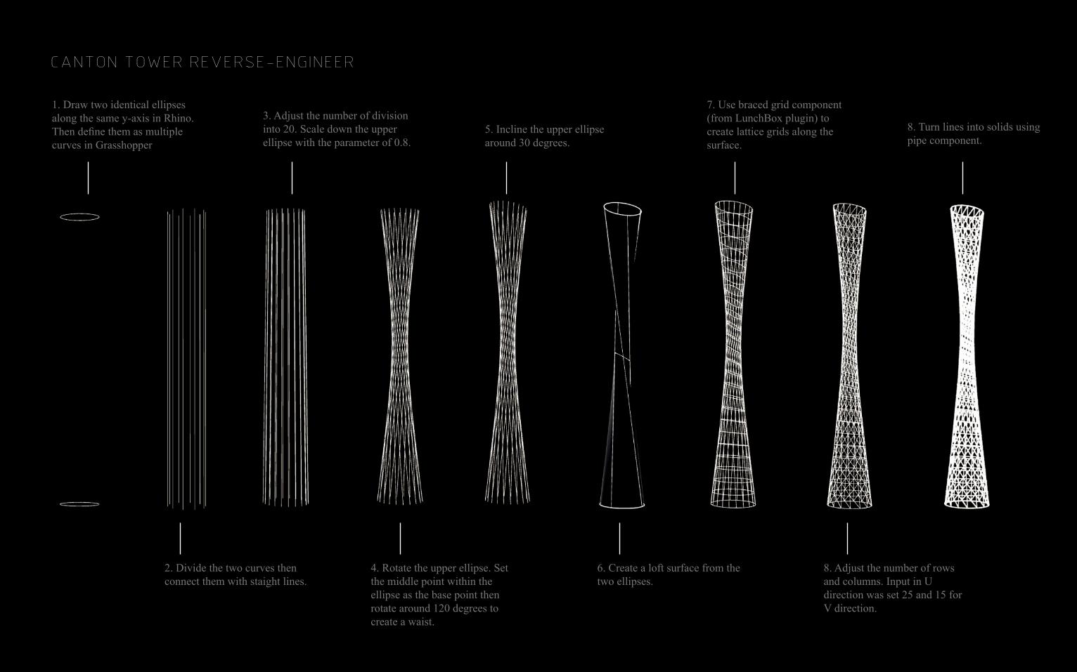
CANTON TOWER REVERSE-ENGINEER
1. Draw two identical ellipses along the same y-axis in Rhino. Then define them as multiple curves in Grasshopper
2. Divide the two curves then connect them with staight lines.
3. Adjust the number of division into 20. Scale down the upper ellipse with the parameter of 0.8.
4. Rotate the upper ellipse. Set the middle point within the ellipse as the base point then rotate around 120 degrees to create a waist.
5. Incline the upper ellipse around 30 degrees.
6. Create a loft surface from the two ellipses.
7. Use braced grid component (from LunchBox plugin) to create lattice grids along the surface.
8. Adjust the number of rows and columns. Input in U direction was set 25 and 15 for V direction.
8. Turn lines into solids using pipe component.
1. 141.
15
CANTON TOWER REVERSE-ENGINEER

1. 161.
17
B.4 TECHNIQUE DEVELOPMENT
In this section, I developed some iterations derived from the Grasshopper definition for Canton Tower. Variables for these iterations are basically the curve type, number of rows, columns, and the degree of rotation. Through the exploration, I found that the number of rows and columns would affect the overall
visual impact, as the smaller the numbers are, the less curvy the structure seems. But in all iterations, the basic idea remains unchanged, that all lines are in perfectly straight.
Developing the technique which I learned from Canton Tower actually inspired me on some new opportunities. Decreasing the number of rows and columns not only makes the whole structure look much simpler, but also shows a more tensile structure. Each line does not represent a steel tube anymore.
It’s no longer a compression element as in Canton Tower, but instead it turns into a tension element, which represents strings, cables, ropes etc. Adjusting the subtle angle of each string is the key to give the whole structure a dynamic form.

1. 181.
19
I would want my design to achieve dynamic and continuity in form. Strings are different from normal construction materials. In most cases, they are not even included in conventional architecture or housings because they are soft and almost invisible. But on another hand, a series of strings compose a surface, which can be vague and easily integrate to its surrounding environment. Therefore dynamic and continuity are the two crucial criteria for my design. Meanwhile, considering the fabrication of an actual model can be complicated, simplicity is another important factor I will count in my design.
My most satisfied iteration is the triangular twisting tunnel outlined by perfectly straight strings, as it meets my criteria of dynamic, continuity, and simplicity. The form reminds me on stringed instruments. Therefore I would explore the possibility on a huge walk-in musical instrument, which plays actual sound when strings are vibrating.
1. 201.
21
B.5 TECHNIQUE: PROTOTYPE
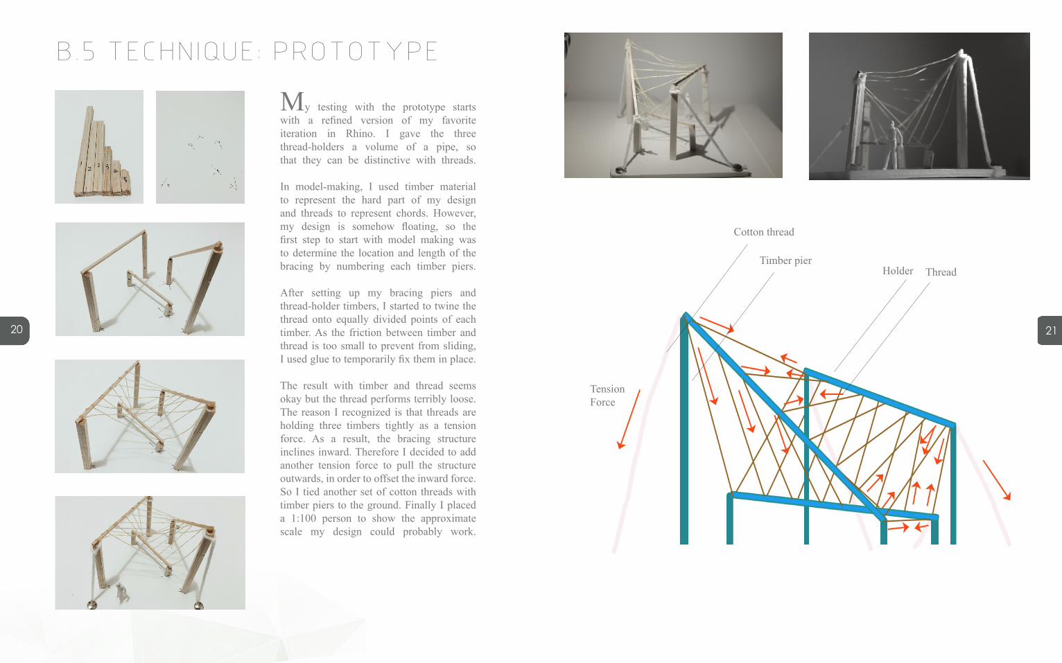
My testing with the prototype starts with a refined version of my favorite iteration in Rhino. I gave the three thread-holders a volume of a pipe, so that they can be distinctive with threads.
In model-making, I used timber material to represent the hard part of my design and threads to represent chords. However, my design is somehow floating, so the first step to start with model making was to determine the location and length of the bracing by numbering each timber piers.
After setting up my bracing piers and thread-holder timbers, I started to twine the thread onto equally divided points of each timber. As the friction between timber and thread is too small to prevent from sliding, I used glue to temporarily fix them in place.
The result with timber and thread seems okay but the thread performs terribly loose. The reason I recognized is that threads are holding three timbers tightly as a tension force. As a result, the bracing structure inclines inward. Therefore I decided to add another tension force to pull the structure outwards, in order to offset the inward force. So I tied another set of cotton threads with timber piers to the ground. Finally I placed a 1:100 person to show the approximate scale my design could probably work.
Timber pierHolder
Tension Force
Thread
Cotton thread

1. 221.
23
ANCHORING THREAD
In the first attempt, glue was used to anchor the thread onto the timber temporarily. However it’s not a practical nor a stable way to proceed. Therefore my group mate and I worked together particularly on the joint of timber and thread. We’ve discovered three ways to connect two elements:
ONE. Twine the thread onto the pin which was inserted into the timber. It’s the easiest and quickest way to do, but the thread is very likely to slide off.
TWO. Pass through the pin with a hole on its end. It’s easy and efficient. But it can be loose if either end of the thread is not anchored tightly.
THREE. Twine the thread onto the pin then knot. It’s time-consuming but tight, and each thread works independently in terms of tightness and stiffness.
Yet, our options are not limited to these three ways. There are certainly much more options to be discovered, such as sewing, or customized 3D printed joint elements, as long as the structure is stable, strings are tight, and preferably each string works independently to make different sound. Besides, the materials are not limited to timber and thread either. More case studies on actual musical instruments can be done to help discover more opportunities on acoustic materials, such as base wood, ebony, bamboo for a hard part, and brass, bronze or even natural fibers.
B.6 TECHNIQUE: PROPOSAL
1. 241.
25
B.6 TECHNIQUE:PROPOSAL- CHORD BRIDGE
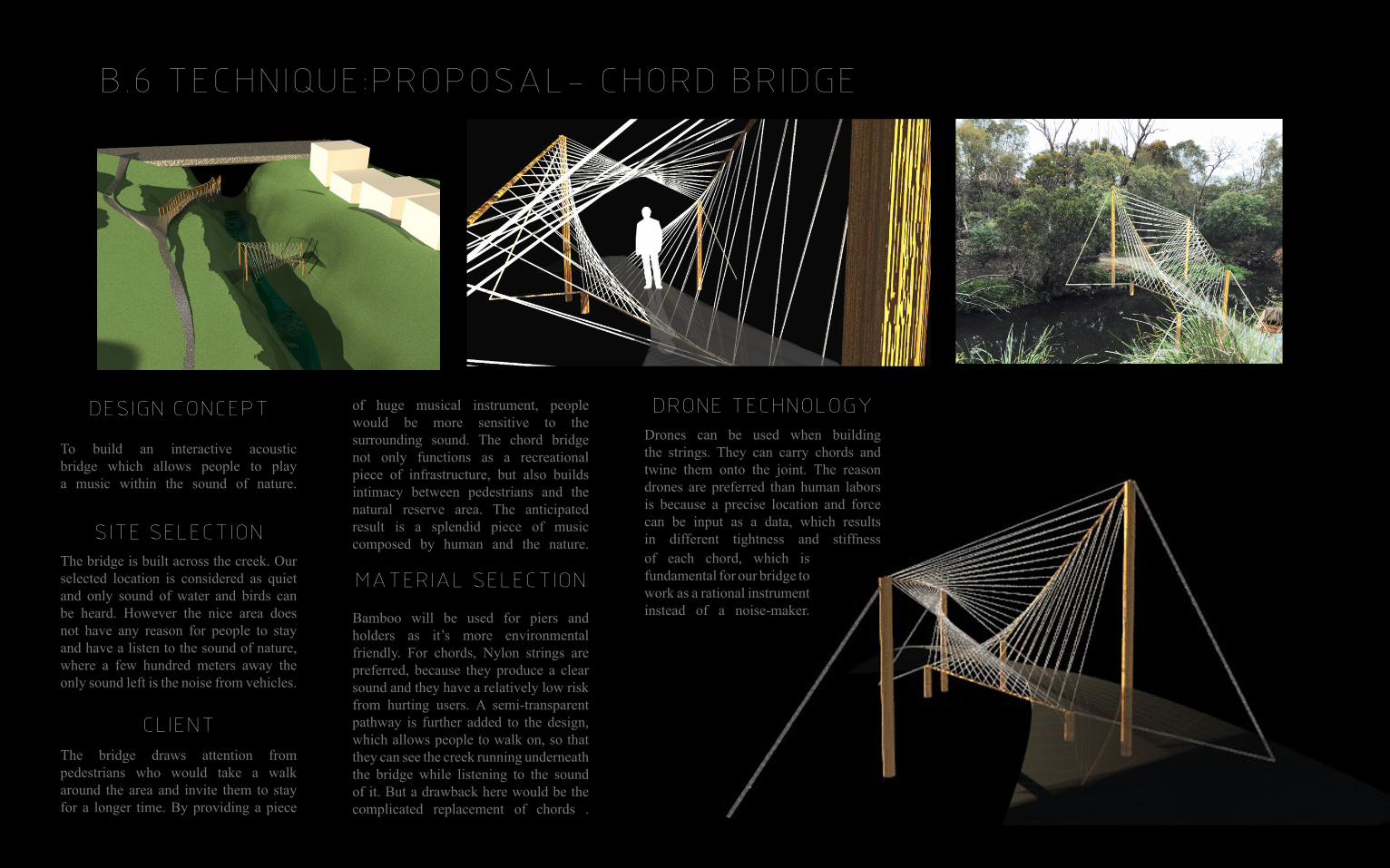
DESIGN CONCEPT
To build an interactive acoustic bridge which allows people to play a music within the sound of nature.
SITE SELECTIONThe bridge is built across the creek. Our selected location is considered as quiet and only sound of water and birds can be heard. However the nice area does not have any reason for people to stay and have a listen to the sound of nature, where a few hundred meters away the only sound left is the noise from vehicles.
CLIENTThe bridge draws attention from pedestrians who would take a walk around the area and invite them to stay for a longer time. By providing a piece
of huge musical instrument, people would be more sensitive to the surrounding sound. The chord bridge not only functions as a recreational piece of infrastructure, but also builds intimacy between pedestrians and the natural reserve area. The anticipated result is a splendid piece of music composed by human and the nature.
MATERIAL SELECTION
Bamboo will be used for piers and holders as it’s more environmental friendly. For chords, Nylon strings are preferred, because they produce a clear sound and they have a relatively low risk from hurting users. A semi-transparent pathway is further added to the design, which allows people to walk on, so that they can see the creek running underneath the bridge while listening to the sound of it. But a drawback here would be the complicated replacement of chords .
DRONE TECHNOLOGYDrones can be used when building the strings. They can carry chords and twine them onto the joint. The reason drones are preferred than human labors is because a precise location and force can be input as a data, which results in different tightness and stiffness of each chord, which is fundamental for our bridge to work as a rational instrument instead of a noise-maker.

1. 261.
27
B.7 LEARNING OBJECTIVES AND OUTCOMES
Our studio looks into the construction technology of building with drones. In the ETH Zurich's article of ‘Building a Bridge with Flying Robots2, the author has particularly researched on the fabrication of tensile structures with quadrocopters. The same idea is applicable with my design of a chord bridge. In terms of construction for our design, it will be good to divide them into two phases. The first phase will be erecting supporting bamboo structures with human labor force. For the second phase, using quadrocopter is a good option to stretch the strings.
FIG1. DJI PHANTOM VISION+ QUADCOPTER FIG2. DRONE-BUILT ROPE BRIDGE
NODESIntersections of strings and structure can be realized by flying machines. In prototyping models, we found the nodes can be easily slid away. Therefore we decided to carve a thin piece, smaller than ¼ of the bamboo tube, to form a notch where can anchor the nodes. Follow the drawing of knots, a node is realized as a series of circular movements. Assuming there is enough flying space.
In previous research and experiments, the flying machine creates a surface-like structure by flying a zigzag with an additional pullback movement after every crossing. Similarly, a pullback is necessary for our structure in order to achieve tightness and independency of each string.
DRONE SET UPA quadcopter is able to move in every direction but the unpredictability is the problem that needs to be overcome. GPS and IMU would make the flying machine more precise on x-y axis as they tell locations and horizontal movement. And pressure sensor with a LiDar would provide feedback on the height spontaneously. Futher, a semi-dense visual odometry for a monocular camera would allow for a better control in an environment. However, the unpredictability still results in a 2-meter deviation, which is the most destructive factor for the bridge construction. Unless the deviation is controlled in 20cm (which is the proximate interval of each string), a simple shift away could cause crossing of strings, and unpredictable sound, and more importantly, it might ruin the whole aesthetic experience of a parametric design. Another factor needs to be concerned is whether the drone has the capability to pull the strings in a particular force, for example, 10 Newtons. It’s the most crucial part of the final performance of chords, as well as the strongest reason to build in a drone instead of human labors. If the force cannot be controlled, substitutions need to be found to achieve similar outcome, such as acceleration and vectors, which might affect the force.
LEARNING OUTCOMEIn doing part B, I became more familiar and able to use Grasshopper as a parametric design tool. By doing iterations I explored how different parameters could have a large effect on the basic model and how they generates new opportunities. The form of my design is actually derived from one of the iterations from Canton Tower, but it has a completely different looking and function. Using Grasshopper has now taken place of my original purpose of using Rhino, even a simple command I would prefer to do it in Grasshopper because it allows changes to happen and opens more possibilities for an innovative design. Fabricating physical model prototype helps it make more sense of my design in terms of scale, material effects, geometry, and assembly. My research on drone technologies enabled me to be critical on my design as some parts are not practical. Drone technologies set limit for my design, not only the material weight and complexity of construction process, but also a deeper meaning behind the design and constructability. In next stage I will focus into detailed design, where each joint will be specified and a more detailed drone construction workflow will be outlined.
2. Ammar Mirjan et, al. (2016). Building a Bridge with Flying Robots. Springer International Publishing Switzerland

1. 281.
29
B.8 APPENDIX -ALGORITHMIC SKETCHES
JOKER PORTRAI BUILDINGIMAGE SAMPLING
PANELEVALUATING FIELDS
1. 301.
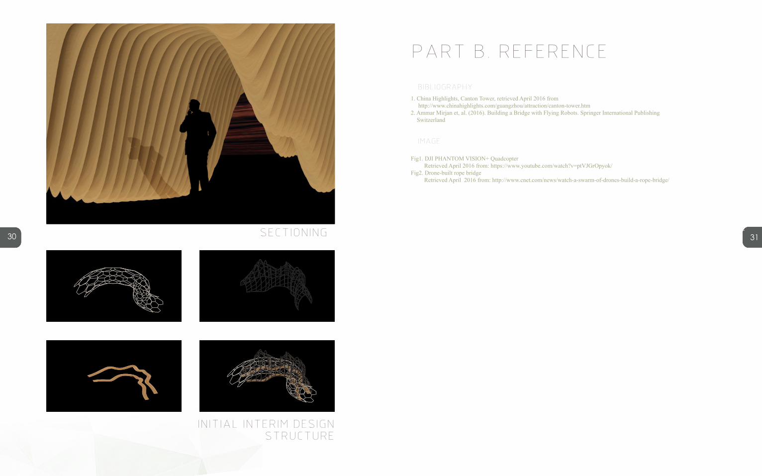
31SECTIONING
INITIAL INTERIM DESIGN STRUCTURE
PART B. REFERENCE
1. China Highlights, Canton Tower, retrieved April 2016 from http://www.chinahighlights.com/guangzhou/attraction/canton-tower.htm2. Ammar Mirjan et, al. (2016). Building a Bridge with Flying Robots. Springer International Publishing Switzerland
Fig1. DJI PHANTOM VISION+ Quadcopter Retrieved April 2016 from: https://www.youtube.com/watch?v=ptVJGrOpyok/Fig2. Drone-built rope bridge Retrieved April 2016 from: http://www.cnet.com/news/watch-a-swarm-of-drones-build-a-rope-bridge/
BIBLIOGRAPHY
IMAGE