gone through enough circuits - the-eye.euthe-eye.eu/public/books/electronic...
TRANSCRIPT

A radio signal has to start in an oscillator circuit, so you definitely have a "need to know"
BY THOMAS McMULLEN, W1 SL
Before I became a Radio Amateur, I thought I knew about oscillators. After all, I had tuned many a transmitter in my Navy days, and it was a snap - set dial A to 34.9, turn on the "TUNE" switch, and adjust knob B for minimum plate current on the master oscillator. Next, tune knob C ... etc.
The FCC exams of the day specified that you must draw a circuit diagram, and I lucked
18 m July 1979
out - they asked for a neutralized-triode power amplifier. Those I knew about, because we had those in the Navy, too, and it was essential to know how to neutralize the beasts.
However, I met my Waterloo when I tried to build my first oscillator for my first ham rig. I built it "just like the book, except .... " It didn't work. I rebuilt, and rebuilt, and rebuilt. It didn't work. By the time I had
gone through enough circu its to begin to see what was happening, or not happening, the orig inal circuit was so out of date that I never did go back and try to make it work. Bu t, I did learn about oscillators. (The next step was learning how to stop a circu it from oscillating, but that's a whole nuther story!)
So, here's the inside workings of oscillator circuits, presented in the hope that you'll have an easier time with them than I did, and that these words will be of some help when you find an oscillator circuit in a rig you're work ing on, or on your General Class (or higher) exam.
Amplifiers
No, no, I'm not off the track when I start talking about an ampl ifier circuit. It's just that , in order to understand what makes an oscillator work, you must first know about amplif iers. It is a fact of electronic li fe that an oscillator is simply an amplifier with positive feedback, i.e., feedback that is aiding the original applied voltage. It is also true that, in order to sustain oscillation, an amp lifier must have enough gain to overcome the losses in the circu it.
Tubes and transistors have a trait called, natural ly enough, amplification factor. This is simply the amount by which a signal is increased as it goes through the .device. You' ll find a column listing the amplification factor in most vacuumtube manuals and tables. The nearest equivalent listing for a bipolar transistor is the beta (/3), or current amplification factor, sometimes expressed hFE or hte· It's the ratio of base current to collector current. For example, if a transistor has a beta of 50, then 1 mA of current through the base would cause 50 mA of collector current to flow.
If you'll look at Fig. 1, you will see a representative ampli-

tier circuit with sine-wave drawings - one as an input signal, the other as the output. I've chosen arbitrary values to make the action easy to follow. Assuming an ampl ification of 10, a 1-volt input signal will produce an output voltage of 10. This is actually a variable de voltage on the plate of the tube, caused by variations in plate current through the dropping resistor (RP.) to the plate. However, it will be interpreted by following stages (and an osci lloscope) as an alternating current (ac) voltage. (I suppose, if you really want to be picky about it, that it is an alternating-polarity voltage, because it swings both posit ive and negative with respect to a zero-reference point. However, convention says we've always called it an ac voltage; so be it.)
Phase That plate resistor brings the
discussion to another critical part of amplifier circuitry, which will require a bit of explanation so you can follow what is happening.
Note that the sine wave at the plate is upside-down compared with that at the grid. This is called out-of-phase. Here's why it happens that way.
The current that flows through the plate circuit of a tube is determined by the volt-
.-----+----<l OUTPUT
Fig. 1. An amplifier inc reases the ampli· tude of a signal applied to the grid. In ad· di ti on to the i ncreased strength (voltage) of the output signal , note that it is oppo· site in phase, that is, where the grid volt· age goes in a positive direction, the out· put vo ltage is moving in a negative direction, and vice versa.
age on the grid. In Fig. 2, let's assume the tube has zero volts on the grid, and a plate current of 5 mA. This current flow through the plate resistor causes a voltage drop across it of 50 volts. This is called a " static," or nonmoving voltage; nothing is changing. Now, increase the grid voltage to +1 volt. A positive grid voltage causes more current to flow, which means that the de voltage on the plate decreases to 40 volts. It's simple Ohm's law; E = IR = 6 m A (. 006A) X 10,000 ohms = 60 volts. Subtract the voltage across the resistor from the plate supply, (1 OOV - 60V) and you have 40 volts left.
Okay, you can see that a positive voltage on the grid causes a plate voltage swing in the opposite (decreasing) direction, so let's try it for a nega· tive voltage. Now, apply negative 1 volt to the grid. This causes less plate current to flow, which means that the voltage drop across the resistor decreases, allowing the plate voltage to climb back up, toward the positive supply voltage. Thus, you can see that the voltage on the plate always does the opposite of that on the grid (out of phase), while the current through the plate circuit follows the grid voltage, therefore is in phase. See Appendix A at the end of this article for further discussion of phase.
Feedback
Here's the trick that makes an oscillator different from an amplifier. For an amplifier to amplify, you must first give it a voltage to work with. Now, suppose you pried loose a bit of the output voltage and fed it back to the input, letting the amplifier supply its own input voltage to work on. Perpetual motion? Well, no, but selfsustaining ... almost. As long as the gain of the amplifier is great enough to overcome any losses (resistors in the signal
~-----c sov
- IOOV +
Fig. 2. For purposes of discussion in the text, an ampl ifier is set up in a zero sig· nal condition, wi th zero bias on the grid, to draw a plate current of 5 milliamperes, causing the voltage drop across t he plate resistor to be 50 vo lts. Changi ng the bias in either a pos itive or negat ive direct ion w ill cause a co rresponding change in plate current and voltage drop across the resistor.
path, poor insulation , capacitance to ground), the signal will sustain itself, producing an output voltage, which is fed back to the grid, which produces an output voltage . . . on and on.
Just a minute! What's to keep the plate voltage from getting bigger and bigger and bigger? A thing called saturation, that's what. When the grid vol tage gets negative enough to completely cut-off the flow of plate current; zero current through the resistor means a voltage drop of zero, and the voltage on the plate is now equal the supply vo ltage. That 's as far as it can swing in that direction. When the grid is positive enough to cause maximum plate current to f low through the resistor, the vo ltage across the res istor is equal to the supply voltage, and the plate has zero voltage on it (well, almost zero - nothing is perfect). That' s as far as it can go in that di rection. At either of these two points, the ampli fier is saturated; it just can' t work any harder, and that's al l you can get out of it.
Now, here is where things begin to get tricky: In order for the amp I ifier to osci I late, the voltage fed back to the grid must be in phase wi th what is already there. Think about it. If you have a negat ive voltage on the grid, causing the plate voltage to increase (in a positive direction), and take a
July 1979 m 19

+ RFC
~-
Fig. 3. One type of ampli fier can be thought of as a cathode follower - the output voltage is taken from the cathode of the tube (or from the emitter in a transistor), and has the same phase as the input voltage. This feature, plus the two capaci tors, C1 and C2, serving as a voltage divider, is particularly useful in one type of osci llator, as explained in Fig. 4 and the text
slice of that positive voltage and apply it to the grid, it'll immediately cause the plate voltage to decrease, thus turning itself off! Obviously, there's something mi ssing here.
Reactance
That's the missing word; reactance. Now, don't get scared - it's not al I that hard to understand. Reactance in an electronic circuit is pretty much the same as it is in people. It means you (or the circui t) react to a stimulus or input. The result of people reacting is often unpredictable; sometimes the act ion is delayed, sometimes it is the exact opposite of what was expected. Fortunately, electronic circuits are much more predictable, and they will follow the rules very closely.
Both capacitors and inductors have reactance - they oppose a change in the way things are. A capaci tor causes the current to lead (go ahead of) the voltage. An inductor does just the opposite; current lags (falls behind) the voltage. Another term for what these gadgets do is phase shift -they shift the phase of the vo ltage or current wi th respect to each other. Does a spark of an idea begin to glimmer about here? How about connecting a capac itor between the plate
20 m July 1979
and the grid of the tube? Introduce some phase shift, allowing the amplifier to keep itself going (oscillate).
Nope, it doesn't work. (You didn't really think it would be that simple, did you?) A capacitor shi fts the phase by 90 degrees, and the plate is 180 degrees out of phase, which leaves the other 90 trying to turn the works off again. (Oh, yes, there are some circuits which will oscillate with such simple feedback arrangements, caused most ly by stray circu it defects - it's not always a dependable or predictable thing, however.)
Here's the secret: Get rid of that resistor in the plate circuit! Why? All it is doing is soaking up power, and keeping the plate at exactly 180 degrees out of phase with the grid. Put an inductance in there, or better yet, a tuned c ircu it (inductance and capacitance in parallel). Now, things can happen! The voltage at the plate end of the tuned circuit doesn' t have to stay exact ly out of phase with the grid, and if you detour a bit of the vo ltage and feed it back to the grid (through a capac itor with its 90-degree shift), you'll get the right kind of act ion through the circuit to keep the oscillations going as long as you feed power to it.
Improvements
This osc illator is pretty basic, and can stand considerable improvement. For one thing, because the plate voltage is deliberately misadjusted (with the tuned circuit) to be something other than precisely 180 degrees out of phase, it is ineffic ient. It also produces a lot of harmonics because of this slightly off-resonan ce condition. As the saying goes: "there's gotta be a better way."
There defin itely is, and one of them is shown in Fig. 3. Note that the plate circuit now has a simple inductance in it - no tuned circuit at all. You could even put the resistor
back in. That inductor, by the way, is called an rf choke (RFC). In combination with C3, it keeps any rf voltage that may be on the plate from getting into the power supply where it could cause trouble. Where's the feedback? Look at the cathode. It has a resistor connected to it, right? Note that the resistor is still in the path t he current must take to get from the power supply through the tube, and back to the supply again.
That means that whatever goes through the plate also must go through the cathode, which means that the signal (a voltage change caused by varying current) w ill appear on the cathode too (as long as there is no big capaci tor to shunt it to ground, that is).
So, just connect a capaci tor from the cathode to the grid, and there's the feedback path again, you say? Goll y, you're almost right. You've noticed that the phase is the same (the cathode voltage is in phase with the grid), so the feedback will help the ampl if ier, creating oscillations. Actual ly, there is no need to apply the entire cathode vol tage to the grid -you would drive it in to saturation right away. Let's use a voltage divider. Remember, capacitors have reactance, wh ich appears to be res istance at rad io frequenc ies. The larger the value of capacitance
Fig. 4. In thi s osci llator, cal led a Colpi tts, the feedback path is from the cathode to the grid, through C3. C4 helps l imit the maximum va lue that the vol tage can reach. The frequency of osci llation is determined by the tuned ci rcuit L 1/C1. The plate of the tube is at rt ground because o f the bypass capacitor, C5. The rt choke prevents st ray rt from gett ing into the power su pply.

(bigger numbers), the smaller the apparent resistance (and vice versa). Two capacitors in series make a convenient voltage divider for rt energy, with C2 (in Fig. 3) shunting part of the cathode voltage to ground, and C1 feeding some of that voltage to the grid. This circuit is called a Colpitts oscillator, by the way, in honor of its inventor.
How does it know what frequency to oscillate at? Well, if you left it alone, it would work at whatever frequency was "fed back" the most efficiently, i.e., with the correct amount of phase shift. Fortunately, it is easy to coerce (that's a polite word for arm-twisting) it into doing what we want - just connect a tuned circuit to the grid, as in Fig. 4. A tuned circuit appears to be a high resistance at its resonant frequency, but a very low resistance at all other frequencies. Any signal that was fed back to the grid, but not at the same frequency as the tuned circuit, would see what appeared as a short-circuit to ground. A signal at the proper frequency would face several thousand ohms to ground, and thus would reach the grid and be amplified.
If you change the value of the variable capacitor (C1), or the inductor (L1), or both, you'll change the frequency at which the combination is resonant, thus changing the frequency of oscillation; you've just invented a variable-frequency oscillator (VFO)!
Oscillator types
There are many different ways of providing proper feedback for an oscillator, and Figs. 5 through 7 show some of the more common circuits. They travel by different names, usually based on the early experimenter who developed them. Some are called by different names in foreign countries because they, too, had plenty of experimenters and some of them worked on a particular circuit at the same
111 II I 11 1 ...
u
•
Cl
- +
RFC
LI
Fig. 5. Some representative oscillator types. The one at A is an Armstrong circuit, with the feedback path by means of magnetic coupling shown by the dashed l ines between the top coil and the one to the grid. This small coi l was called the " tickler," and in early receivers, the strength of oscillation could be adjusted by changing the position of the ti ckler with respect to the grid coi l. Many circuits had the grid resistor, R2, positioned across capacitor C2 as shown by the dotted A2A - it was then referred to as a " gridleak" resistor because it allowed a small amount of current to leak across the capacitor. Frequency of oscillation was determined by L 1/C1. The oscillator at B is a " tunedplatel tuned-grid" type, with the feedback path being mainly the internal capacitance from grid to plate of the tube. A Hartley oscillator is shown at C, with its characteristic tapped coil. The feedback path is shown in heavy lines, from the cathode, through the coil to ground. This induces current in the upper half, which reaches the grid. The Colpitts oscillator, at D, avoids the nuisance of a tapped coi l by usi ng the voltage-divider principle to control the amount of signal on the grid. Feedback is from the plate to the bottom of the oscillator coil.
time as Americans did. Some circuits are simply variations of a basic type, named after the guy who made a modification or improvement to the original. As an example, you might hear of a Clapp oscillator - in England it's called a Gouriet· Clapp oscillator - which is basically a modification of the Colpitts wherein the tuned circuit is arranged so that the capacitor and inductor are in series, rather than arranged in parallel.
Another version of the Colpitts is called a Vackar oscillator in some parts of the world, and a Vackar-Tesla in others. Many improvements or modifications were made in an attempt to obtain an oscillator that was more stable than the original.
At any rate, the object is to find the basic feedback path so you can identify the oscillator and understand what makes it work. The feedback is not always provided by capacitors, as you'll note in Fig. SA, which
is called an Armstrong circuit, and Fig. SC, a Hartley circuit. The path in both is inductive, meaning that the magnetic lines of force around a coil of wire cut across another coil of wire, thus inducing a voltage across it. It's easy to follow in the Armstrong circuit, but perhaps not so obvious in the Hartley. The current from the cathode, through the lower portion of the coi I, causes a build-up of lines of force, which cut across the windings above the tap point, thus providing some voltage on the grid.
Incidentally, if you're worried about remembering the names of some of these oscillators -it's not absolutely vital that you do, except as a means of impressing newcomers with your knowledge - a trick I've used is to say, " It's hard to tap the coil in a Hartley, but easy to split the capacitor in a Colpitts."
The Armstrong oscillator circuit saw a lot of use in the early days; it was a favorite for
July 1979 m 21
regenerat ive receiver types, but is seldom seen in modern equipment.
The representative circuits I've shown here have the feedback path emphasized by heavy
0
RI
CJ
+
Fig. 6. Crystal-controlled oscillators use a quartz crystal in place of a t uned circu it. Shown at A is the familiar Colpitts circui t with the capacitors forming a feedback-control circuit. The Pierce c ir· cuit, B, is somewhat of a " brute force" osci llator, with the crystal connected di· rect ly from plate to grid. Some circuits use a capacitor in series with the crystal to keep plate voltage from appearing at the crystal socket.
lines in the drawings. Also, I have included a couple of circuits which are crystal con-trol led. A crystal is simply another means of selecting one particular frequency; it takes the place of a tuned circuit made up of a coil and capacitor.
One of the crystal-controlled circuits which has been a favorite among vhf enthusiasts for years is the Pierce, Fig. 68. Note the crystal between the plate and grid of the tube. The crystal in this instance is providing the correct amount of phase shift, at the proper frequency, to allow the circuit to oscillate.
I've used tubes in the circuits talked about, mainly because it is a bit easier to follow the signal path and current flow with vacuum tubes. Some transistor circuits require tricky de biasing circuits, and the feedback path
22 m July 1979
is not always so obvious as with tubes. However, a transistorized Colpitts (note the split capaci tor, C1a/C1 b) is shown in Fig. 7.
Identification, please
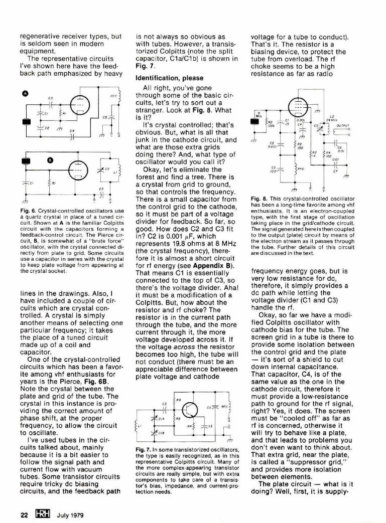
All right, you've gone through some of the basic ci rcuits, let's try to sort out a stranger. Look at Fig. 8. What is it?
It's crystal controlled; that's obvious. But, what is all that junk in the cathode circuit, and what are those extra grids doing there? And, what type of oscillator would you call it?
Okay, let's eliminate the forest and find a tree. There is a crystal from grid to ground, so that controls the frequency. There is a small capacitor from the control grid to the cathode, so it must be part of a voltage divider for feedback. So far, so good. How does C2 and C3 fit in? C2 is 0.001 µ.F, which represents 19.8 ohms at 8 MHz (the crystal frequency), therefore it is almost a short circuit for rf energy (see Appendix B). That means C1 is essentially connected to the top of C3, so there's the voltage divider. Aha! it must be a modification of a Colpitts. But, how about the resistor and rf choke? The resistor is in the current path through the tube, and the more current through it, the more voltage developed across it. If the voltage across the resistor becomes too high, the tube will not conduct (there must be an appreciable difference between plate voltage and cathode
LI CJ
Fig. 7. In some transistorized oscil lators, the type is easily recognized, as in this representative Colpitts circuit. Many of the more complex-appearing transistor circuits are really simple, but with extra components to take care of a transistor's bias, impedance, and current-protection needs.
voltage for a tube to conduct). That's it. The resistor is a biasing device, to protect the tube from overload. The rf choke seems to be a high resistance as far as radio
8 MHr
RZ 100/t.
CZ 0 .001
CJ 100
+
Fig. 8. This crystal -control led oscillator has been a long-t ime favorite among vhf enthusiasts. It is an electron-coupled type, with the first stage of osci llat ion taking place in the grid/cathode ci rcuit. The signal generated here is then coupled to t he output (plate) ci rcui t by means of the electron stream as it passes t hrough the tube. Further details of this circuit are discussed in the text.
frequency energy goes, but is very low resistance for de, therefore, it simply provides a de path while letting the voltage divider (C1 and C3) handle the rf.
Okay, so far we have a modified Colpitts oscillator with cathode bias for the tube. The screen grid in a tube is there to provide some isolation between the control grid and the plate - it's sort of a shield to cut down internal capacitance. That capacitor, C4, is of the same value as the one in the cathode circu it, therefore it must provide a low-resistance path to ground for the rf signal, right? Yes, it does. The screen must be "cooled off" as far as rt is concerned, otherwise it will try to behave like a plate, and that leads to problems you don't even want to think about. That extra grid, near the plate, is called a " suppressor grid," and provides more isolation between elements.
The plate circuit - what is it doing? Well, first, it is supply-

ing a de path to keep things going. Second, it has a tuned (resonant) circuit connected to it , and the circuit is working at three times the crystal frequency! It emphasizes the harmonic energy that is produced by the crystal-oscillator portion of the circuit, thus providing useful output on multiples of the crystal frequency. Because of the peculiar phase relationships that exist in a circuit of this type, it works out that the odd multiples are most emphasized. You can get useful output on three, five, seven, or nine times the crystal frequency. The higher the order of
Appendix A
The term "cycle" is another way of saying circle - returning to the point of start. When you push a person on a swing, you start a cycle with a push, the swing moves away, goes through an arc, swings back toward you, and you give it another push. That's one complete cycle. Electrical (and electronic) terms use degrees around a circle to keep track of the exact position of a voltage or current as it goes through a cycle, see Fig. 9A. The importance in being in phase or out of phase can be seen in Fig. 98. Sine wave X starts at
multiplication, the lower the power output , however. In practice, most circuits of this type are limited to a multiplication of either three or five.
So, there you have it. The oscillator is a modified Colpitts, with harmonic output at three times the crystal frequency. It has been used in many vhf rigs to obtain some of the frequency multiplication necessary for transmitters operating at 50 or 144 MHz. Oh, yes, just to cover the remaining unexplained components - R3 and R4 are in the circuit to provide a bit of over-current protection for the tube, and C6 and C?
the zero-voltage point, moves toward the positive side, then negative, and completes a cycle. If you start sine wave Y just a bit later, it is said to "lag" sine wave X by 90 degrees. In an extreme case, sine wave Z is started after X has already completed half of its cyc le - Z is going positive at the same time X is going negative, therefore Z "lags" X by 180 degrees. The two voltages cancel each other, and the net result is zero, assuming that both are of equal strength.
Appendix B
Capacitors have reactance (resistance) to alternating cur-
-- - - -- - ----- -- - --- ----- - ~ - -v- 2ro A 2r o CYCLE (C IRCLE) 'W SIN [ - WAV£(CYCL C)
Fig. 9. The term "phase" is often used in alternating-current discussions, including radio frequencies. It is a means of identifying the prec ise position of any part of a sine wave as it travels through a cycle - starting at O degrees and ending at 360, as in A. Carrying the phase shift to an extreme can cause one wave to cancel another by being 180 degrees out of phase, as shown by wave Z at B.
bypass any stray rt energy to ground, keeping it out of the power supply wiring.
That's what oscillators are all about. It wasn't too difficult , really. Oh, of course there are any number of refinements that can be made to these basic circuits, but once you know what to look for it is easy to ignore the distractions. Note that I've left a lot of bias circuits and the filament (heater) connections out of the diagrams, just for clarity. These are just incidental to the operation of an amplifier with positive feedback - alias an oscillator!
rent energy, and it varies with frequency, that's why you cannot buy a "1-ohm" capaci-tor, as you can with resistors. The formula for calculating capacitive reactance is:
x - 1 c - 27rFC
Where F is in megahertz (MHz) and c is in microfarads (µF).
To work out the reactance of C2 at 8 MHz in Fig. 8:
x, = 1 6. 28 x 8 x 0.001
= _l_ = 19.9 ohms 0.05024
The reactance of C2. at the output frequency, 24 MHz, is:
1 x, = 6.28 x 24 x 0.001
= - 1- = 6. 63 ohms 0.15072
You can see that this valuable feature of reactance dependent upon frequency allows you to play all sorts of games with the circuit. Radio-frequency energy can be led through a circuit just the way you want, simply by providing a series of high- or low-resistance paths for it.
HRH
July 1979 m 23