gold rx/px/cx/sd manual for alarms and information messages · manual for alarms and information...
TRANSCRIPT

MANUAL FOR ALARMS AND INFORMATION MESSAGES
GOLD RX/PX/CX/SDGeneration FApplicable to Program Version 1.28 and newer versions

2 www.swegon.com We reserve the right to alter specifications without notice.
GB.GOLDSKFLARM.181221
Content
The document was originally written in Swedish.
Innehåll
1. Alarm Descriptions with Factory Settings ............. 3
2. Information Messages .......................................... 24

www.swegon.com 3We reserve the right to alter specifications without notice.
GB.GOLDSKFLARM.181221
Alarm No. Alarm textFunction
Priority Stop Delay Resetting
0 = Blocked 0 = In oper. s = second 0 = manual
Dis
pla
y
Co
mm
. A = A alarm 1 = Stop m = minute 1 = automatic
B = B alarm h=hour
Alarm group 1: Fire alarm1:1 1 EXTERNAL FIRE ALARM NO. 1 TRIPPED
For the fire protection function connected to terminals 6-7.
A1) 1 3 s 0
1:2 2 EXTERNAL FIRE ALARM NO. 2 TRIPPEDFor the fire protection function connected to terminals 8-9.
A1) 1 3 s 0
1:3 3 INTERNAL FIRE ALARM TRIPPEDThe air handling unit’s supply air sensor measures more than 70 °C and/or its extract air temperature sensor measures more than 50 °C. The function must be activated manually.
A1) 1 3 s 0
Alarm group 2: External alarm2:1 16 EXTERNAL ALARM NO. 1 TRIPPED
External alarm, connected to control unit terminals 10-11, has tripped..
A 13) 1 s2) 0
2:2 17 EXTERNAL ALARM NO. 2 TRIPPEDExternal alarm, connected to control unit terminals 12-13, has tripped..
B 03) 1 s2) 0
Alarm group 3: Pre-heating3:1 31 PRE-HEAT, I/O MODULE NO. 9 COMMUNICATION ER-
RORThe air handling unit’s control unit cannot establish correct communication with I/O module No. 9 for pre-heating.
A 03) 10 s 1
3:2 32 PRE-HEATING, OVERHEATING PROTECTION TRIPPED OR NO SUPPLY VOLTAGE TO THE ELECTRICAL HEATERThe overheating protection has tripped or there is no supply voltage to the electrical heater.
A1) 03) 10 s 0
3:3 33 PRE-HEAT, FROST GUARD TRIPPEDFrost guard temperature sensor measures temperature less than preset alarm limit.Factory setting: 7 °C.
A1) 1 5 s 0
3:4 34 PRE-HEAT, FROST GUARD TEMPERATURE SENSOR DEFECTIVEFrost guard temperature sensor is defective or is not connected.
A1) 1 3 s 1
3:5 35 PRE-HEAT, TEMPERATURE SENSOR DEFECTIVESensor is defective or is not connected.
A 03) 3 s 1
3:6 36 PRE-HEAT, VALVE MONITORING TRIPPEDValve actuator, air heater for water is defective.
A 03) 10 m 0
3:7 37 PRE-HEAT, TEMPERATURE BELOW SET POINT ALARM LIMITTemperature is below preset set point longer than 20 minutes.
A 03) 20 m 0
3:8 38 PRE-HEAT, ALARM INPUT TRIPPEDAlarm input pre-heat has tripped.
A 0 20 s 0
Alarm group 4: Extra regulation sequence4:1 46 EXTRA REGULATION SEQUENCE 1, I/O-MODULE No E
COMMUNICATION ERRORThe air handling unit's control unit cannot establish correct communication with I/O module No. E for extra regulation sequence.
A 03) 10 s 1
1. Alarm Descriptions with Factory Settings

4 www.swegon.com We reserve the right to alter specifications without notice.
GB.GOLDSKFLARM.181221
Alarm No. Alarm textFunction
Priority Stop Delay Resetting
0 = Blocked 0 = In oper. s = second 0 = manual
Dis
pla
y
Co
mm
. A = A alarm 1 = Stop m = minute 1 = automatic
B = B alarm h=hour
4:2 47 EXTRA REGULATION SEQUENCE 1, OVERHEATING PROTECTION TRIPPED OR NO SUPPLY VOLTAGE TO THE ELECTRICAL HEATER The overheating protection has tripped or there is no supply voltage to the electrical heater.
A1) 03) 10 s 0
4:3 48 EXTRA REGULATION SEQUENCE 1, FROST GUARD TRIPPEDFrost guard temperature sensor measures temperature less than preset alarm limit.Factory setting: 7 °C.
A1) 1 5 s 0
4:4 49 EXTRA REGULATION SEQUENCE 1, FROST GUARD TEMPERATURE SENSOR DEFECTIVEFrost guard temperature sensor is defective or is not connected.
A1) 1 3 s 1
4:5 50 EXTRA REGULATION SEQUENCE 1, VALVE MONITOR-ING TRIPPED Valve actuator, air heater for water, is defective.
B 03) 10 m 0
4:6 51 EXTRA REGULATION SEQUENCE 1, ALARM INPUT TRIPPEDAlarm input extra regulation sequence has tripped.
A 0 20 s 0
4:7 52 EXTRA REGULATION SEQUENCE 1, TEMPERATURE PROTECTION VIA COMMUNICATION, COMMUNICA-TION ERRORThe air handling unit’s control unit is not receiving any temperature reading via the external communication interface within the preset time limit.
B 0 5 m 1
4:8 53 EXTRA REGULATION SEQUENCE 1, COMBI COIL SENSOR DEFECTIVETemperature sensor to the combi coil is defective or not connected.
A 1 3 s 1
4:9 54 EXTRA REGULATION SEQUENCE 2, I/O-MODULE No F COMMUNICATION ERRORThe air handling unit's control unit cannot establish correct communication with I/O module No. E for extra regulation sequence.
A 03) 10 s 1
4:10 55 EXTRA REGULATION SEQUENCE 2, OVERHEATING PROTECTION TRIPPED OR NO SUPPLY VOLTAGE TO THE ELECTRICAL HEATERThe overheating protection has tripped or there is no supply voltage to the electrical heater.
A1) 03) 10 s 0
4:11 56 EXTRA REGULATION SEQUENCE 2, FROST GUARD TRIPPEDFrost guard temperature sensor measures temperature less than preset alarm limit.Factory setting: 7 °C.
A1) 1 5 s 0
4:12 57 EXTRA REGULATION SEQUENCE 2, FROST GUARD TEMPERATURE SENSOR DEFECTIVEFrost guard temperature sensor is defective or is not connected.
A1) 1 3 s 1
4:13 58 EXTRA REGULATION SEQUENCE 2, VALVE MONITOR-ING TRIPPED Valve actuator, air heater for water, is defective.
B 03) 10 m 0
4:14 59 EXTRA REGULATION SEQUENCE 2, ALARM INPUT TRIPPEDAlarm input extra regulation sequence has tripped.
A 0 20 s 0

www.swegon.com 5We reserve the right to alter specifications without notice.
GB.GOLDSKFLARM.181221
Alarm No. Alarm textFunction
Priority Stop Delay Resetting
0 = Blocked 0 = In oper. s = second 0 = manual
Dis
pla
y
Co
mm
. A = A alarm 1 = Stop m = minute 1 = automatic
B = B alarm h=hour
4:15 60 EXTRA REGULATION SEQUENCE 2, COMBI COIL SENSOR DEFECTIVETemperature sensor to the combi coil is defective or not connected.
A 1 3 s 1
Alarm group 5: Reheating5:1 61 RE-HEATING, OVERHEATING PROTECTION TRIPPED OR
NO SUPPLY VOLTAGE TO THE ELECTRICAL HEATERThe overheating protection has tripped or there is no supply voltage to the electrical heater.
A1) 03) 10 s 0
5:2 62 REHEAT, FROST GUARD TRIPPEDFrost guard temperature sensor measures temperature less than preset alarm limit.Factory setting: 7 °C.
A1) 1 5 s 0
5:3 63 REHEAT, FROST GUARD TEMPERATURE SENSOR DE-FECTIVEFrost guard temperature sensor is defective or is not connected.
A1) 1 3 s 1
5:4 64 REHEAT, VALVE MONITORING TRIPPED Valve actuator, air heater for water is defective.
B 03) 10 m 0
5:5 65 RE-HEATING, ALARM INPUT TRIPPEDAlarm input reheating has tripped.
A 0 20 s 0
Alarm group 6: Xzone I/O-module no. A6:1 76 Xzone, I/O-MODULE NO. A COMMUNICATION ERROR
The air handling unit's control unit cannot establish correct communication with I/O module No. A for Xzone.
A 03) 10 s 1
6:2 77 Xzone, OVERHEATING PROTECTION TRIPPED OR NO SUPPLY VOLTAGE TO THE ELECTRICAL HEATERThe overheating protection has tripped or there is no supply voltage to the electrical heater.
A1) 03) 10 s 0
6:3 78 Xzone, FROST GUARD TRIPPEDFrost guard temperature sensor measures temperature less than preset alarm limit.Factory setting: 7 °C.
A1) 1 5 s 0
6:4 79 Xzone, FROST GUARD TEMPERATURE SENSOR DEFEC-TIVEFrost guard temperature sensor is defective or is not connected.
A1) 1 3 s 1
6:5 80 Xzone, SUPPLY AIR TEMPERATURE SENSOR DEFECTIVESupply air sensor is defective or is not connected.
A 13) 3 s 1
6:6 81 Xzone, HEATING VALVE MONITORING TRIPPED Valve actuator, air heater for water is defective.
B 03) 10 m 0
6:7 82 Xzone, SUPPLY AIR TEMPERATURE BELOW SET POINT ALARM LIMITThe supply air temperature is below the preset set point (ERS and Supply air regulation) or Min SA temp (Extract air regulation) longer than 20 minutes.
A 03) 20 m 0
6:8 83 Xzone, SUPPLY AIR TEMPERATURE ABOVE SET POINT ALARM LIMITThe supply air temperature is above the preset set point (ERS and Supply air regulation) or Max. SA temp (Extract air regulation) longer than 20 minutes.
B 03) 20 m 0
6:9 84 Xzone, HEAT, ALARM INPUT TRIPPEDAlarm input Xzone heat has tripped.
A 0 20 s 0
Alarm group 7: Xzone I/O-module no. B

6 www.swegon.com We reserve the right to alter specifications without notice.
GB.GOLDSKFLARM.181221
Alarm No. Alarm textFunction
Priority Stop Delay Resetting
0 = Blocked 0 = In oper. s = second 0 = manual
Dis
pla
y
Co
mm
. A = A alarm 1 = Stop m = minute 1 = automatic
B = B alarm h=hour
7:1 91 Xzone, I/O-MODULE NO. B COMMUNICATION ERRORThe air handling unit's control unit cannot establish correct communication with I/O module No. B for Xzone.
A 03) 10 s 1
7:2 92 Xzone, EXTRACT AIR TEMPERATURE SENSOR DEFEC-TIVEExtract air sensor is defective or is not connected.
A 13) 3 s 1
7:3 93 Xzone, COOLING VALVE MONITORING TRIPPED Valve actuator, air cooler for water is defective.
B 03) 10 m 0
7:4 94 Xzone, EXTRACT AIR TEMPERATURE SENSOR BELOW SET POINT ALARM LIMITThe extract air temperature is below preset alarm limit for more than 20 minutes.
A 03) 20 m 0
7:5 95 Xzone, COOL, ALARM INPUT 1 TRIPPEDAlarm input 1 Xzone cool has tripped.
A 0 20 s 0
7:6 96 Xzone, COOL, ALARM INPUT 2 TRIPPEDAlarm input 2 Xzone cool has tripped.
A 0 20 s 0
Alarm group 8: Cooling8:5 110 COOLING, VALVE MONITORING TRIPPED
Valve actuator, air cooler, is defective.B 03) 10 s 0
8:6 111 COOLING ALARM INPUT 1 TRIPPEDAlarm input 1 cooling has tripped.
A 0 20 s 0
8:7 112 COOLING ALARM INPUT 2 TRIPPEDAlarm input 2 cooling has tripped.
A 0 20 s 0
Alarm group 9: SpareAlarm group 10: AHU, internal temperature sensor
10:1 136 SUPPLY AIR TEMPERATURE SENSOR DEFECTIVESupply air sensor is defective or is not connected.
A 13) 3 s 1
10:2 137 SUPPLY AIR TEMPERATURE SENSOR FOR DENSITY COMPENSATION DEFECTIVESupply air sensor in the supply air fan intake cannot establish correct communication or shows an incorrect value.
B 03) 3 s 1
10:3 138 EXTRACT AIR TEMPERATURE SENSOR DEFECTIVEExtract air sensor is defective or is not connected.
A 13) 3 s 1
10:4 139 EXTRACT AIR TEMPERATURE SENSOR FOR DENSITY COMPENSATION DEFECTIVE (GOLD RX/PX/CX) Temperature sensor in extract air fan intake cannot establish correct communication or shows incorrect value.GOLD RX Exhaust air regulation has been selected, but the tem-perature sensor in the exhaust air is defective or is not connected.
B 03) 3 s 1
10:5 140 EXTRACT AIR TEMPERATURE SENSOR FOR HEAT EX-CHANGER DEFROSTING DEFECTIVETemperature sensor, for heat exchanger defrosting is defective.
A 13) 10 s 1
10:6 141 EXTRACT AIR TEMPERATURE SENSOR FOR DENSITY COMPENSATION IN SD AHU DEFECTIVE Temperature sensor in extract air fan intake cannot establish correct communication or shows incorrect value.
A 13) 10 s 1
www.swegon.com 7We reserve the right to alter specifications without notice.
GB.GOLDSKFLARM.181221
Alarm No. Alarm textFunction
Priority Stop Delay Resetting
0 = Blocked 0 = In oper. s = second 0 = manual
Dis
pla
y
Co
mm
. A = A alarm 1 = Stop m = minute 1 = automatic
B = B alarm h=hour
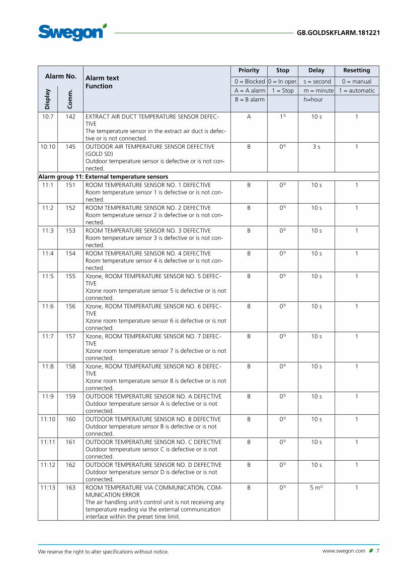
10:7 142 EXTRACT AIR DUCT TEMPERATURE SENSOR DEFEC-TIVE The temperature sensor in the extract air duct is defec-tive or is not connected.
A 13) 10 s 1
10:10 145 OUTDOOR AIR TEMPERATURE SENSOR DEFECTIVE (GOLD SD)Outdoor temperature sensor is defective or is not con-nected.
B 03) 3 s 1
Alarm group 11: External temperature sensors11:1 151 ROOM TEMPERATURE SENSOR NO. 1 DEFECTIVE
Room temperature sensor 1 is defective or is not con-nected.
B 03) 10 s 1
11:2 152 ROOM TEMPERATURE SENSOR NO. 2 DEFECTIVERoom temperature sensor 2 is defective or is not con-nected.
B 03) 10 s 1
11:3 153 ROOM TEMPERATURE SENSOR NO. 3 DEFECTIVERoom temperature sensor 3 is defective or is not con-nected.
B 03) 10 s 1
11:4 154 ROOM TEMPERATURE SENSOR NO. 4 DEFECTIVERoom temperature sensor 4 is defective or is not con-nected.
B 03) 10 s 1
11:5 155 Xzone, ROOM TEMPERATURE SENSOR NO. 5 DEFEC-TIVEXzone room temperature sensor 5 is defective or is not connected.
B 03) 10 s 1
11:6 156 Xzone, ROOM TEMPERATURE SENSOR NO. 6 DEFEC-TIVEXzone room temperature sensor 6 is defective or is not connected.
B 03) 10 s 1
11:7 157 Xzone, ROOM TEMPERATURE SENSOR NO. 7 DEFEC-TIVEXzone room temperature sensor 7 is defective or is not connected.
B 03) 10 s 1
11:8 158 Xzone, ROOM TEMPERATURE SENSOR NO. 8 DEFEC-TIVEXzone room temperature sensor 8 is defective or is not connected.
B 03) 10 s 1
11:9 159 OUTDOOR TEMPERATURE SENSOR NO. A DEFECTIVEOutdoor temperature sensor A is defective or is not connected.
B 03) 10 s 1
11:10 160 OUTDOOR TEMPERATURE SENSOR NO. B DEFECTIVEOutdoor temperature sensor B is defective or is not connected.
B 03) 10 s 1
11:11 161 OUTDOOR TEMPERATURE SENSOR NO. C DEFECTIVEOutdoor temperature sensor C is defective or is not connected.
B 03) 10 s 1
11:12 162 OUTDOOR TEMPERATURE SENSOR NO. D DEFECTIVEOutdoor temperature sensor D is defective or is not connected.
B 03) 10 s 1
11:13 163 ROOM TEMPERATURE VIA COMMUNICATION, COM-MUNICATION ERRORThe air handling unit’s control unit is not receiving any temperature reading via the external communication interface within the preset time limit.
B 03) 5 m2) 1

8 www.swegon.com We reserve the right to alter specifications without notice.
GB.GOLDSKFLARM.181221
Alarm No. Alarm textFunction
Priority Stop Delay Resetting
0 = Blocked 0 = In oper. s = second 0 = manual
Dis
pla
y
Co
mm
. A = A alarm 1 = Stop m = minute 1 = automatic
B = B alarm h=hour
11.14 164 Xzone, ROOM TEMPERATURE VIA COMMUNICATION, COMMUNICATION ERRORThe air handling unit’s control unit is not receiving any temperature reading via the external communication interface within the preset time limit.
B 03) 5 m2) 1
11:15 165 OUTDOOR TEMPERATURE VIA COMMUNICATION, COMMUNICATION ERRORThe air handling unit’s control unit is not receiving any temperature reading via the external communication interface within the preset time limit.
B 03) 5 m2) 1
Alarm group 12: AHU, temperature diff.12:1 166 SUPPLY AIR TEMPERATURE BELOW SET POINT ALARM
LIMITThe supply air temperature is lower than the preset set point (ERS, ORS, ORE and Supply air regulation) or has deviated from the supply air controller’s current set point (Extract air regulation) longer than 20 minutes.
A 13) 20 m 0
12:2 167 SUPPLY AIR TEMPERATURE ABOVE SET POINT ALARM LIMITThe supply air temperature is above the preset set point (ERS, ORS, ORE and Supply air regulation) or has deviated from the supply air controller’s current set point (Extract air regulation) longer than 20 minutes.
B 03) 20 m 0
12:6 171 EXTRACT AIR TEMPERATURE BELOW ALARM LIMITThe extract air temperature is below preset alarm limit for more than 20 minutes.
A 13) 20 m 0
12:11 176 TEMPERATURE PROTECTION BELOW ALARM LIMITThe temperature protection reading is below preset alarm limit.
A 13) 30 s2) 0
12:13 178 HEAT EXCHANGER EFFICIENCY BELOW ALARM LIMITThe heat exchanger's efficiency is below the preset alarm limit for more than 2 minutes.
B 03) 2 hrs. 0
Alarm group 13: Humidity/VOC13:1 181 HUMIDIFICATION, I/O MODULE NO. 4 COMMUNICA-
TION ERRORThe air handling unit's control unit cannot establish correct communication with I/O module No. 4 for humidity.
B 03) 10 s 1
13:2 182 SUPPLY AIR HUMIDITY SENSOR DEFECTIVEThe humidity sensor in the supply air duct is defective or is not connected.
A 03) 10 s 1
13:3 184 EXTRACT AIR HUMIDITY SENSOR DEFECTIVEThe humidity sensor in the extract air duct is defective or is not connected.
A 03) 10 s 1
13:4 184 EXHAUST AIR HUMIDITY SENSOR DEFECTIVEThe humidity sensor in the exhaust air duct is defective or is not connected.
A 03) 10 sec. 1
13:9 189 HUMIDIFIER, ALARM OUTPUT TRIPPEDThe humidifier has tripped alarm output.
A 03) 10 s 0
13:11 191 VOC SENSOR COMMUNICATION ERRORThe air handling unit's control unit cannot establish correct communication with the VOC sensor.
B 03) 10 s 1
13:12 192 VOC SENSOR, INTERNAL COMMUNICATION ERRORThe air handling unit's control unit cannot achieve cor-rect communication with the VOC sensor.
B 03) 60 s 1
13:13 193 VOC SENSOR, INTERNAL ERRORVOC sensor defective.
B 03) 60 s 1

www.swegon.com 9We reserve the right to alter specifications without notice.
GB.GOLDSKFLARM.181221
Alarm No. Alarm textFunction
Priority Stop Delay Resetting
0 = Blocked 0 = In oper. s = second 0 = manual
Dis
pla
y
Co
mm
. A = A alarm 1 = Stop m = minute 1 = automatic
B = B alarm h=hour
13:14 194 VOC SENSOR, LEVEL BELOW/ABOVE SET POINT ALARM LIMITThe VOC sensor has read a level below or above the set point alarm limit for more than 60 seconds.
B 03) 60 s 1
Alarm group 14: SpareAlarm group 15: Plate heat exchanger
15:1 211 PLATE HEAT EXCHANGER, I/O-MODULE NO. 2 COM-MUNICATION ERRORThe air handling unit's control unit cannot establish correct communication with I/O module No. 2 for plate heat exchanger.
A 13)4) 10 s 1
15:2 212 PLATE HEAT EXCHANGER, TEMPERATURE SENSOR NO. 1 DEFECTIVETemperature sensor 1 for frost guard in heat exchanger cube is defective or is not connected.
A 13)4) 3 s 1
15:3 213 PLATE HEAT EXCHANGER, TEMPERATURE SENSOR NO. 2 DEFECTIVETemperature sensor 2 for frost guard in heat exchanger cube is defective or is not connected.
A 13)4) 3 s 1
15:4 214 PLATE HEAT EXCHANGER, DAMPER MONITORING TRIPPEDDamper actuator for plate heat exchanger is defective.
A 03)4) 10 m 0
15:7 217 PLATE HEAT EXCHANGER, I/O-MODULE NO. 3 COM-MUNICATION ERRORThe air handling unit's control unit cannot establish correct communication with I/O module No. 3 for the plate heat exchanger.
A 13)4) 10 s 1
15:8 218 PLATE HEAT EXCHANGER, BYPASS DAMPER MONI-TORING TRIPPEDThe bypass damper monitoring function of the plate heat exchanger has tripped.
A 03)4) 10 m 0
15:9 219 PLATE HEAT EXCHANGER, DAMPER NO. 1 MONITOR-ING TRIPPEDThe section damper 1 monitoring function of the plate heat exchanger has tripped.
A 03)4) 10 m 0
15:10 220 PLATE HEAT EXCHANGER, DAMPER NO. 2 MONITOR-ING TRIPPEDThe section damper 2 monitoring function of the plate heat exchanger has tripped.
A 03)4) 10 m 0
15:11 221 PLATE HEAT EXCHANGER, I/O-MODULE NO. 3 COM-MUNICATION ERRORThe air handling unit's control unit cannot establish correct communication with I/O module No. 3 for the plate heat exchanger.
A 13)4) 10 s 1
15:12 222 PLATE HEAT EXCHANGER, BYPASS DAMPER MONI-TORING TRIPPEDThe bypass damper monitoring function of the plate heat exchanger has tripped.
A 03)4) 10 m 0
15:13 223 PLATE HEAT EXCHANGER, COUNTER-FLOW, DEFROST-ING PRESSURE OVER ALARM LIMITThere has been a continuous need for full defrosting for 2 hours.
B 13)4) 2 h 0
15:14 224 PLATE HEAT EXCHANGER, DEFROSTING SENSOR NO. C COMMUNICATION ERRORThe air handling unit’s control unit cannot establish correct communication with defrosting sensor C for the heat exchanger.
B 0 10 m 1

10 www.swegon.com We reserve the right to alter specifications without notice.
GB.GOLDSKFLARM.181221
Alarm No. Alarm textFunction
Priority Stop Delay Resetting
0 = Blocked 0 = In oper. s = second 0 = manual
Dis
pla
y
Co
mm
. A = A alarm 1 = Stop m = minute 1 = automatic
B = B alarm h=hour
15:15 225 PLATE HEAT EXCHANGER, DEFROSTING PRESSURE OVER ALARM LIMITThe need for defrosting has been over 95% continu-ously for 144 minutes.
B 1 2.4 h 0
Alarm group 16: Coil heat exchangers16:1 226 COIL HEAT EXCHANGER, I/O-MODULE NO. 1 COM-
MUNICATION ERRORThe air handling unit's control unit cannot establish correct communication with I/O module No. 1 for coil heat exchanger.
A 13)4) 10 s 1
16:2 227 COIL HEAT EXCHANGER, TEMPERATURE SENSOR DEFECTIVEThe temperature sensor on the coil heat exchanger’s pipework package for the frost guard is defective or is not connected.
A 13)4) 3 s 1
16:3 228 COIL HEAT EXCHANGER, VALVE MONITORING TRIPPEDValve actuator of the coil heat exchanger is defective.
A 03)4) 10 m 0
16:4 229 COIL HEAT EXCHANGER, PUMP MONITORING TRIPPEDNo in-service indication from the pump is obtained.
A 13)4) 20 s 0
16:5 230 COIL HEAT EXCHANGER, I/O-MODULE NO. C COM-MUNICATION ERRORThe air handling unit's control unit cannot establish correct communication with I/O module No. C for coil heat exchanger.
A 1 10 s 1
16:6 231 COIL HEAT EXCHANGER, PRESSURE SENSOR DEFEC-TIVEPressure sensor for the coil heat exchanger is defective or is not connected.
A 1 10 m 1
16:7 232 COIL HEAT EXCHANGER, LOW PRESSURE IN HYDRONIC CIRCUITPressure gauge registers a too low pressure.
A 1 5 m 0
16:8 233 COIL HEAT EXCHANGER, PRESSURE BELOW ALARM LIMITFluid pressure sensor registers a too low pressure.
A 1 10 s 1
Alarm group 17: Rotary heat exchanger17:1 241 ROTARY HEAT EXCHANGER, MOTOR CONTROLLER
COMMUNICATION ERRORThe air handling unit’s control unit cannot establish correct communication with the heat exchanger mo-tor controller.
A 13)4) 10 s 1
17:2 242 ROTARY HEAT EXCHANGER, DEFROSTING PRESSURE SENSOR NO. 7 COMMUNICATION ERRORThe air handling unit’s control unit cannot establish correct communication with the heat exchanger pres-sure sensor no. 7. Applicable to the defrosting function only.
B 03) 10 s 1
17:3 243 ROTARY HEAT EXCHANGER, DEFROSTING PRESSURE OVER ALARM LIMITThe need for defrosting has been over 95% continu-ously for 144 minutes.
B 13)4) 2,4 h 0
17:4 244 ROTARY HEAT EXCHANGER, ROTATION DETECTOR TRIPPED No impulses from the rotation detector are registered with the heat exchanger controller.
A1) 13)4) 3 s 0

www.swegon.com 11We reserve the right to alter specifications without notice.
GB.GOLDSKFLARM.181221
Alarm No. Alarm textFunction
Priority Stop Delay Resetting
0 = Blocked 0 = In oper. s = second 0 = manual
Dis
pla
y
Co
mm
. A = A alarm 1 = Stop m = minute 1 = automatic
B = B alarm h=hour
17:5 245 ROTARY HEAT EXCHANGER, MOTOR CONTROLLER OVERCURRENTHeat exchanger motor controller has registered exces-sively high current supplier to the drive motor.
A1) 13)4) 3 s 0
17:6 246 ROTARY HEAT EXCHANGER, MOTOR CONTROLLER UNDERVOLTAGELow feed voltage is supplied to the rotary heat ex-changer’s motor controller.
A1) 13)4) 3 s 0
17:7 247 ROTARY HEAT EXCHANGER, MOTOR CONTROLLER OVERVOLTAGEHigh feed voltage is supplied to the rotary heat ex-changer's motor controller.
A1) 13)4) 3 s 0
17:8 248 ROTARY HEAT EXCHANGER, MOTOR CONTROLLER EXCESS TEMPERATUREHigh temperature (90°C) inside the heat exchanger’s motor controller.
A1) 13)4) 3 s 0
17:9 249 ROTARY HEAT EXCHANGER, MOTOR CONTROLLER START UP ERRORDrive motor does not rotate during start up.
A1) 13)4) 3 s 0
Alarm group 18: AYC18:1 256 AYC, I/O MODULE No. 7 COMMUNICATION ERROR
The air handling unit's control unit cannot establish correct communication with I/O module No. 7 for AYC.
A 03) 10 s 1
18:2 257 AYC HEATING, TEMPERATURE SENSOR DEFECTIVEHeating temperature sensor is defective or is not con-nected.
A 03) 3 s 1
18:3 258 AYC HEATING, VALVE MONITORING TRIPPEDThe heated water valve actuator is defective.
B 03) 10 m 0
18:4 259 AYC HEATING, PUMP MONITORING TRIPPEDThe heated water pump is defective.
A 03) 20 s 0
18:5 260 AYC HEATING, TEMPERATURE BELOW SET POINT LIMITHeating water temperature is below preset set point longer than 30 minutes.
A 03) 30 m 0
18:6 261 AYC HEATING, TEMPERATURE ABOVE SET POINT ALARM LIMIT 5)
Heating water temperature exceeds preset set point longer than 30 minutes.
B 03) 30 m 0
18:9 264 AYC COOLING, TEMPERATURE SENSOR DEFECTIVETemperature sensor for the AYC function (All Year Comfort) cooling is defective or is not connected.
A 03) 3 s 1
18:10 265 AYC COOLING, VALVE MONITORING TRIPPEDThe chilled water valve actuator is defective.
B 03) 10 m 0
18:11 266 AYC COOLING, PUMP MONITORING TRIPPEDThe chilled water pump is defective.
A 03) 20 s 0
18:12 267 AYC COOLING, TEMPERATURE BELOW SET POINT ALARM LIMITHeating water temperature is below preset set point longer than 30 minutes.
A 03) 30 m 0
18:13 268 AYC COOLING, TEMPERATURE ABOVE SET POINT ALARM LIMIT 5)
Cooling water temperature exceeds preset set point longer than 30 minutes.
B 03) 30 m 0
Alarm group 19-20: SpareAlarm group 21: COOL DX
12 www.swegon.com We reserve the right to alter specifications without notice.
GB.GOLDSKFLARM.181221
Alarm No. Alarm textFunction
Priority Stop Delay Resetting
0 = Blocked 0 = In oper. s = second 0 = manual
Dis
pla
y
Co
mm
. A = A alarm 1 = Stop m = minute 1 = automatic
B = B alarm h=hour
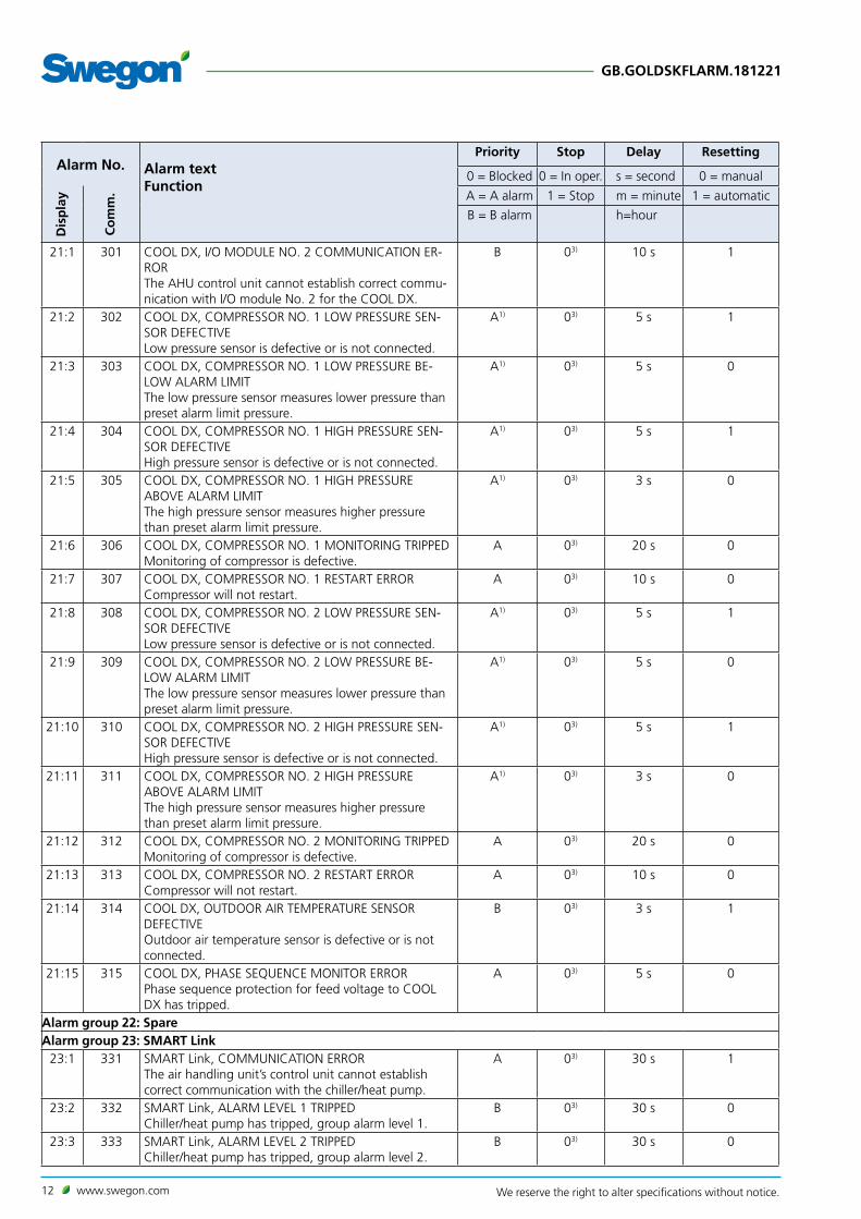
21:1 301 COOL DX, I/O MODULE NO. 2 COMMUNICATION ER-RORThe AHU control unit cannot establish correct commu-nication with I/O module No. 2 for the COOL DX.
B 03) 10 s 1
21:2 302 COOL DX, COMPRESSOR NO. 1 LOW PRESSURE SEN-SOR DEFECTIVELow pressure sensor is defective or is not connected.
A1) 03) 5 s 1
21:3 303 COOL DX, COMPRESSOR NO. 1 LOW PRESSURE BE-LOW ALARM LIMITThe low pressure sensor measures lower pressure than preset alarm limit pressure.
A1) 03) 5 s 0
21:4 304 COOL DX, COMPRESSOR NO. 1 HIGH PRESSURE SEN-SOR DEFECTIVEHigh pressure sensor is defective or is not connected.
A1) 03) 5 s 1
21:5 305 COOL DX, COMPRESSOR NO. 1 HIGH PRESSURE ABOVE ALARM LIMITThe high pressure sensor measures higher pressure than preset alarm limit pressure.
A1) 03) 3 s 0
21:6 306 COOL DX, COMPRESSOR NO. 1 MONITORING TRIPPEDMonitoring of compressor is defective.
A 03) 20 s 0
21:7 307 COOL DX, COMPRESSOR NO. 1 RESTART ERRORCompressor will not restart.
A 03) 10 s 0
21:8 308 COOL DX, COMPRESSOR NO. 2 LOW PRESSURE SEN-SOR DEFECTIVELow pressure sensor is defective or is not connected.
A1) 03) 5 s 1
21:9 309 COOL DX, COMPRESSOR NO. 2 LOW PRESSURE BE-LOW ALARM LIMITThe low pressure sensor measures lower pressure than preset alarm limit pressure.
A1) 03) 5 s 0
21:10 310 COOL DX, COMPRESSOR NO. 2 HIGH PRESSURE SEN-SOR DEFECTIVEHigh pressure sensor is defective or is not connected.
A1) 03) 5 s 1
21:11 311 COOL DX, COMPRESSOR NO. 2 HIGH PRESSURE ABOVE ALARM LIMITThe high pressure sensor measures higher pressure than preset alarm limit pressure.
A1) 03) 3 s 0
21:12 312 COOL DX, COMPRESSOR NO. 2 MONITORING TRIPPEDMonitoring of compressor is defective.
A 03) 20 s 0
21:13 313 COOL DX, COMPRESSOR NO. 2 RESTART ERRORCompressor will not restart.
A 03) 10 s 0
21:14 314 COOL DX, OUTDOOR AIR TEMPERATURE SENSOR DEFECTIVE Outdoor air temperature sensor is defective or is not connected.
B 03) 3 s 1
21:15 315 COOL DX, PHASE SEQUENCE MONITOR ERRORPhase sequence protection for feed voltage to COOL DX has tripped.
A 03) 5 s 0
Alarm group 22: SpareAlarm group 23: SMART Link
23:1 331 SMART Link, COMMUNICATION ERRORThe air handling unit’s control unit cannot establish correct communication with the chiller/heat pump.
A 03) 30 s 1
23:2 332 SMART Link, ALARM LEVEL 1 TRIPPED Chiller/heat pump has tripped, group alarm level 1.
B 03) 30 s 0
23:3 333 SMART Link, ALARM LEVEL 2 TRIPPED Chiller/heat pump has tripped, group alarm level 2.
B 03) 30 s 0

www.swegon.com 13We reserve the right to alter specifications without notice.
GB.GOLDSKFLARM.181221
Alarm No. Alarm textFunction
Priority Stop Delay Resetting
0 = Blocked 0 = In oper. s = second 0 = manual
Dis
pla
y
Co
mm
. A = A alarm 1 = Stop m = minute 1 = automatic
B = B alarm h=hour
23:4 334 SMART Link, ALARM LEVEL 3 TRIPPED Chiller/heat pump has tripped, group alarm level 3.
B 03) 30 s 0
23:10 340 AQUA Link, I/O MODULE NO. 5 COMMUNICATION ERRORThe air handling unit’s control unit cannot establish correct communication with I/O module no. 5, AQUA Link
B 03) 10 s 1
23:11 341 AQUA Link, PUMP MONITORING TRIPPEDPump to AQUA Link is defective.
B 03) 10 s 0
Alarm group 24: SMART Link DX24:1 346 SMART Link, no. 1 communication error
The air handling unit's control unit cannot establish correct communication with the chiller/heat pump 1.
A 03) 30 s 1
24:2 347 SMART Link, no. 1 alarm trippedChiller 1 defective.
A 03) 30 s 1
24:4 349 SMART Link, no. 2 communication errorThe air handling unit's control unit cannot establish correct communication with the chiller/heat pump 2.
A 03) 30 s 1
24:5 350 SMART Link, no. 2 alarm trippedChiller 2 defective.
A 03) 30 s 1
24:7 352 SMART Link, no. 3 communication errorThe air handling unit's control unit cannot establish correct communication with the chiller/heat pump 3.
A 03) 30 s 1
24:8 353 SMART Link, no. 3 alarm trippedChiller 3 defective.
A 03) 30 s 1
24:10 355 SMART Link, no. 4 communication errorThe air handling unit's control unit cannot establish correct communication with the chiller/heat pump 4.
A 03) 30 s 1
24:11 356 SMART Link, no. 4 alarm trippedChiller 4 defective.
A 03) 30 s 1
24:13 358 SMART Link, supply air alarm flow below alarm limitThe alarm supply air flow below alarm limit has tripped.
A 0 10 m 1
Alarm group 24-25: SpareAlarm group 26: Pre-filter
26:1 376 PRE-FILTER, SUPPLY AIR PRESSURE SENSOR NO. 8 COMMUNICATION ERRORThe air handling unit’s control unit cannot establish correct communication with the sensor of the supply air pre-filter.
B 03) 10 s 1
26:2 377 PRE-FILTER, SUPPLY AIR FOULEDThe pressure across the supply air pre-filter exceeds the preset alarm limit for more than 10 minutes.
B 03) 10 m 0
26:7 382 PRE-FILTER, EXTRACT AIR PRESSURE SENSOR NO. 9 COMMUNICATION ERRORThe air handling unit's control unit cannot establish correct communication with the sensor of the extract air pre-filter.
B 03) 10 s 1
26:8 383 PRE-FILTER, EXTRACT AIR FOULEDThe pressure across the extract air pre-filter exceeds the preset alarm limit for more than 10 minutes.
B 03) 10 m 0
Alarm group 27: AHU, internal filters

14 www.swegon.com We reserve the right to alter specifications without notice.
GB.GOLDSKFLARM.181221
Alarm No. Alarm textFunction
Priority Stop Delay Resetting
0 = Blocked 0 = In oper. s = second 0 = manual
Dis
pla
y
Co
mm
. A = A alarm 1 = Stop m = minute 1 = automatic
B = B alarm h=hour
27:1 391 AHU FILTER, SUPPLY AIR PRESSURE SENSOR NO. 3/4 COMMUNICATION ERRORThe air handling unit's control unit cannot establish correct communication with the sensor of the AHU supply air filter.
B 03) 10 s 1
27:2 392 AHU FILTER, SUPPLY AIR FOULEDThe pressure across the AHU supply air filter has exceeded the preset alarm limit for more than 10 minutes.
B 03) 10 m 0
27:7 397 AHU FILTER, EXTRACT AIR PRESSURE SENSOR NO. 3/4 COMMUNICATION ERRORThe air handling unit's control unit cannot establish correct communication with the sensor of the AHU extract air filter.
B 03) 10 s 1
27:8 398 AHU FILTER, EXTRACT AIR FOULEDThe pressure across the AHU extract air filter has exceeded the preset alarm limit for more than 10 minutes.
B 03) 10 m 0
Alarm group 28: Final filter28:1 406 END FILTER, SUPPLY AIR PRESSURE SENSOR NO. A
COMMUNICATION ERRORThe air handling unit's control unit cannot establish correct communication with the sensor of the supply air end filter.
B 03) 10 s 1
28:2 407 END FILTER, SUPPLY AIR, FOULEDThe pressure across the supply air end filter has exceed-ed the preset alarm limit for more than 10 minutes.
B 03) 10 m 0
Alarm group 29: SpareAlarm group 30: Flow measurement
30:1 436 AIRFLOW MEASUREMENT, SUPPLY AIR PRESSURE SEN-SOR NO. 1/2 COMMUNICATION ERRORThe air handling unit's control unit cannot establish correct communication with the flow pressure sensor in the supply air.
A 13) 10 s 1
30:2 437 AIRFLOW MEASUREMENT, SUPPLY AIRFLOW BELOW SET POINT ALARM LIMITThe supply airflow has gone below its set point by more that 10%, during a longer period than 20 min-utes.
B 03) 20 m 0
30:3 438 AIRFLOW MEASUREMENT, SUPPLY AIRFLOW ABOVE SET POINT ALARM LIMITThe supply airflow has exceeded its set point by more that 10%, during a longer period than 20 minutes.
B 03) 20 m 0
30:6 441 AIRFLOW MEASUREMENT, EXTRACT AIR PRESSURE SENSOR NO. 1/2 COMMUNICATION ERRORThe air handling unit's control unit cannot establish correct communication with the flow pressure sensor in the extract air.
A 13) 10 s 1
30:7 442 AIRFLOW MEASUREMENT,EXTRACT AIRFLOW BELOW SET POINT ALARM LIMITThe extract airflow has gone below its set point by more that 10%, during a longer period than 20 min-utes.
B 03) 20 m 0
30:8 443 AIRFLOW MEASUREMENT, EXTRACT AIRFLOW ABOVE SET POINT ALARM LIMITThe extract airflow has exceeded its set point by more that 10%, during a longer period than 20 minutes.
B 03) 20 m 0

www.swegon.com 15We reserve the right to alter specifications without notice.
GB.GOLDSKFLARM.181221
Alarm No. Alarm textFunction
Priority Stop Delay Resetting
0 = Blocked 0 = In oper. s = second 0 = manual
Dis
pla
y
Co
mm
. A = A alarm 1 = Stop m = minute 1 = automatic
B = B alarm h=hour
30:11 446 AIRFLOW MEASUREMENT, PURGING PRESSURE SEN-SOR NO. B COMMUNICATION ERRORThe air handling unit's control unit cannot establish correct communication with the sensor of the rotary heat exchanger purging sector.
B 03) 10 s 1
Alarm group 31: Pressure regulation31:1 451 PRESSURE REGULATION, SUPPLY AIR PRESSURE SEN-
SOR NO. 5 COMMUNICATION ERRORThe air handling unit's control unit cannot establish correct communication with the duct pressure sensor in the supply air. Applies only to pressure regulation of the supply air.
A 13) 10 s 1
31:2 452 PRESSURE REGULATION, SUPPLY AIR PRESSURE BELOW SET POINT ALARM LIMITThe duct pressure has gone below its set point by more that 10%, during a longer period than 20 minutes ( if pressure sensors are connected).
B 03) 20 m 0
31:3 453 PRESSURE REGULATION, SUPPLY AIR PRESSURE ABOVE SET POINT ALARM LIMITThe supply air duct pressure has exceeded its set point by more that 10%, during a longer period than 20 minutes (if pressure sensors are connected).
B 03) 20 m 0
31:6 456 PRESSURE REGULATION, EXTRACT AIR PRESSURE SEN-SOR NO. 6 COMMUNICATION ERRORThe air handling unit's control unit cannot establish correct communication with the duct pressure sensor in the extract air. Applies only to pressure regulation of the extract air.
A 13) 10 s 1
31:7 457 PRESSURE REGULATION, EXTRACT AIR PRESSURE BELOW SET POINT ALARM LIMITThe extract air duct pressure has gone below its set point by more that 10%, during a longer period than 20 minutes (if pressure sensors are connected).
B 03) 20 m 0
31:8 458 PRESSURE REGULATION, EXTRACT AIR PRESSURE ABOVE SET POINT ALARM LIMITThe extract air duct pressure has exceeded its set point by more that 10%, during a longer period than 20 minutes (if pressure sensors are connected).
B 03) 20 m 0
Alarm group 32: ReCO2/Intermittent night heating32:1 466 ReCO2, I/O MODULE NO. 0 COMMUNICATION ERROR
The air handling unit's control unit cannot establish correct communication with I/O module no. 0.
A 03) 10 s 1
32:2 467 ReCO2, PRESSURE SENSOR NO. 0 COMMUNICATION ERRORThe air handling unit's control unit cannot establish correct communication with the pressure sensor.
A 03) 10 s 1
32:3 468 ReCO2/INTERMITTENT NIGHT HEATING, RECIRCULATED AIR DAMPER MONITORING TRIPPEDThe damper actuator does not move to the right posi-tion. The position-confirming output signal from the damper is not the same as the input control signal.
B 03) 10 m 0
32:4 469 ReCO2, OUTDOOR AIR DAMPER MONITORING TRIPPEDThe damper actuator does not move to the right posi-tion. The position-confirming output signal from the damper is not the same as the input control signal.
B 03) 10 m 0
Alarm group 33: Service

16 www.swegon.com We reserve the right to alter specifications without notice.
GB.GOLDSKFLARM.181221
Alarm No. Alarm textFunction
Priority Stop Delay Resetting
0 = Blocked 0 = In oper. s = second 0 = manual
Dis
pla
y
Co
mm
. A = A alarm 1 = Stop m = minute 1 = automatic
B = B alarm h=hour
33:1 481 PERIOD BETWEEN SERVICING PAST ALARM LIMITThe preset service period has expired.If the alarm is RESET via the hand-held terminal, the alarm will be initiated again after 7 days. A new service period can be set and reset under ALARM SETTINGS.
B 03) 5 s 2) 0
33:15 495 LOCK FUNCTION TRIPPEDContact Swegon or their representative.
– – – 06)
Alarm group 34: External controls34:1 496 EXTERNAL CONTROL, I/O MODULE NO. 3 COMMUNI-
CATION ERRORThe air handling unit's control unit cannot establish correct communication with I/O module No. 3 for external control.
B 03) 10 s 1
34:2 497 EXTERNAL CONTROL, I/O MODULE NO. 6 COMMUNI-CATION ERRORThe air handling unit's control unit cannot establish correct communication with I/O module No. 6 for external control.
B 03) 10 s 1
Alarm group 35: Booster diffusers35:1 511 BOOSTER AIR TERMINALS, I/O MODULE NO. 8 COM-
MUNICATION ERRORThe air handling unit's control unit cannot establish correct communication with I/O module No. 8 for Booster diffusers.
B 03) 10 s 1
Alarm group 36: External communication, I/O-modules36:1 526 EXTERNAL COMMUNICATION, I/O MODULE NO. A
COMMUNICATION ERRORThe air handling unit's control unit cannot establish correct communication with I/O module No. A.
B 03) 10 s 1
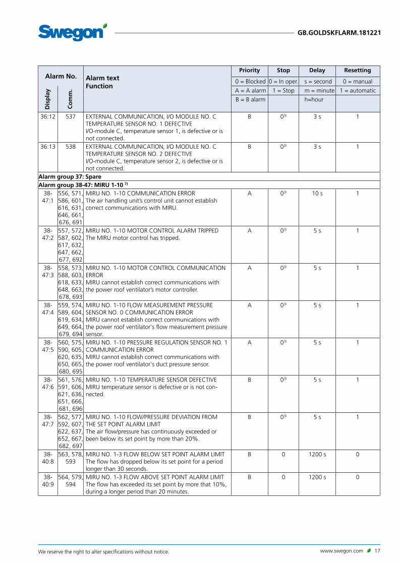
36:2 527 EXTERNAL COMMUNICATION, I/O MODULE NO. A TEMPERATURE SENSOR NO. 1 DEFECTIVEI/O-module A, temperature sensor 1, is defective or is not connected.
B 03) 3 s 1
36:3 528 EXTERNAL COMMUNICATION, I/O MODULE NO. A TEMPERATURE SENSOR NO. 2 DEFECTIVEI/O-module A, temperature sensor 2, is defective or is not connected.
B 03) 3 s 1
36:6 531 EXTERNAL COMMUNICATION, I/O MODULE NO. B COMMUNICATION ERRORThe air handling unit's control unit cannot establish correct communication with I/O module No. B.
B 03) 10 s 1
36:7 532 EXTERNAL COMMUNICATION, I/O MODULE NO. B TEMPERATURE SENSOR NO. 1 DEFECTIVEI/O-module B, temperature sensor 1, is defective or is not connected.
B 03) 3 s 1
36:8 533 EXTERNAL COMMUNICATION, I/O MODULE NO. B TEMPERATURE SENSOR NO. 2 DEFECTIVEI/O-module B, temperature sensor 2, is defective or is not connected.
B 03) 3 s 1
36:11 536 EXTERNAL COMMUNICATION, I/O MODULE NO. C COMMUNICATION ERRORThe air handling unit's control unit cannot establish correct communication with I/O module No. C.
B 03) 10 s 1
www.swegon.com 17We reserve the right to alter specifications without notice.
GB.GOLDSKFLARM.181221
Alarm No. Alarm textFunction
Priority Stop Delay Resetting
0 = Blocked 0 = In oper. s = second 0 = manual
Dis
pla
y
Co
mm
. A = A alarm 1 = Stop m = minute 1 = automatic
B = B alarm h=hour
36:12 537 EXTERNAL COMMUNICATION, I/O MODULE NO. C TEMPERATURE SENSOR NO. 1 DEFECTIVEI/O-module C, temperature sensor 1, is defective or is not connected.
B 03) 3 s 1
36:13 538 EXTERNAL COMMUNICATION, I/O MODULE NO. C TEMPERATURE SENSOR NO. 2 DEFECTIVEI/O-module C, temperature sensor 2, is defective or is not connected.
B 03) 3 s 1
Alarm group 37: SpareAlarm group 38-47: MIRU 1-10 7)
38-47:1
556, 571, 586, 601, 616, 631, 646, 661, 676, 691
MIRU NO. 1-10 COMMUNICATION ERRORThe air handling unit’s control unit cannot establish correct communications with MIRU.
A 03) 10 s 1
38-47:2
557, 572, 587, 602, 617, 632, 647, 662, 677, 692
MIRU NO. 1-10 MOTOR CONTROL ALARM TRIPPEDThe MIRU motor control has tripped.
A 03) 5 s 1
38-47:3
558, 573, 588, 603, 618, 633, 648, 663, 678, 693
MIRU NO. 1-10 MOTOR CONTROL COMMUNICATION ERRORMIRU cannot establish correct communications with the power roof ventilator’s motor controller.
A 03) 5 s 1
38- 47:4
559, 574, 589, 604, 619, 634, 649, 664, 679, 694
MIRU NO. 1-10 FLOW MEASUREMENT PRESSURE SENSOR NO. 0 COMMUNICATION ERRORMIRU cannot establish correct communications with the power roof ventilator's flow measurement pressure sensor.
A 03) 5 s 1
38-47:5
560, 575, 590, 605, 620, 635, 650, 665, 680, 695
MIRU NO. 1-10 PRESSURE REGULATION SENSOR NO. 1 COMMUNICATION ERRORMIRU cannot establish correct communications with the power roof ventilator's duct pressure sensor.
A 03) 5 s 1
38-47:6
561, 576, 591, 606, 621, 636, 651, 666, 681, 696
MIRU NO. 1-10 TEMPERATURE SENSOR DEFECTIVEMIRU temperature sensor is defective or is not con-nected.
B 03) 5 s 1
38-47:7
562, 577, 592, 607, 622, 637, 652, 667, 682, 697
MIRU NO. 1-10 FLOW/PRESSURE DEVIATION FROM THE SET POINT ALARM LIMITThe air flow/pressure has continuously exceeded or been below its set point by more than 20%.
B 03) 5 s 1
38-40:8
563, 578, 593
MIRU NO. 1-3 FLOW BELOW SET POINT ALARM LIMITThe flow has dropped below its set point for a period longer than 30 seconds.
B 0 1200 s 0
38-40:9
564, 579, 594
MIRU NO. 1-3 FLOW ABOVE SET POINT ALARM LIMITThe flow has exceeded its set point by more that 10%, during a longer period than 20 minutes.
B 0 1200 s 0

18 www.swegon.com We reserve the right to alter specifications without notice.
GB.GOLDSKFLARM.181221
Alarm No. Alarm textFunction
Priority Stop Delay Resetting
0 = Blocked 0 = In oper. s = second 0 = manual
Dis
pla
y
Co
mm
. A = A alarm 1 = Stop m = minute 1 = automatic
B = B alarm h=hour
38-40:10
565, 580, 595
MIRU NO. 1-3 PRESSURE BELOW SET POINT ALARM LIMITThe pressure has dropped below its set point for a period longer than 30 seconds.
B 0 1200 s 0
38-40:11
566, 581, 596
MIRU NO. 1-3 PRESSURE ABOVE SET POINT ALARM LIMITThe pressure has exceeded its set point by more that 10%, during a longer period than 20 minutes.
B 0 1200 s 0
Alarm group 49-54: Supply air fan no. 1A-3B 8)
49-54:1
721, 736, 751, 766, 781, 796
SUPPLY AIR FAN 1-3/A-B COMMUNICATION ERRORThe air handling unit's control unit cannot establish correct communication with the supply air fan motor controller.
A 13) 10 s 1
49-54:2
722, 737, 752, 767, 782, 797
SUPPLY AIR FAN 1-3/A-B MOTOR CONTROLLER OVER-CURRENTHigh current supplied to motor
A1) 13) 10 s 0
49-54:3
723, 738, 753, 768, 783, 798
SUPPLY AIR FAN 1-3/A-B MOTOR CONTROLLER UN-DERVOLTAGEVoltage below the normal level is supplied.
A1) 13) 60 s 0
49-54:4
724, 739, 754, 769, 784, 799
SUPPLY AIR FAN 1-3/A-B MOTOR CONTROLLER OVER-VOLTAGEExcessively high voltage is supplied.
A1) 13) 10 s 0
49-54:5
725, 740, 755, 770, 785, 800
SUPPLY AIR FAN 1-3/A-B MOTOR CONTROLLER EX-CESS TEMPERATUREHigh internal temperature.
A1) 13) 10 s 0
49-54:6
726, 741, 756, 771, 786, 801
SUPPLY AIR FAN 1-3/A-B MOTOR CONTROL START UP ERRORSupply air fan does not rotate on a start up, rotates in wrong direction or rotates at excessively high speed.
A1) 13) 10 s 0
49-54:7
727, 742, 757, 772, 787, 802
SUPPLY AIR FAN 1-3/A-B MOTOR CONTROLLER UN-EVEN PHASE VOLTAGEHigh voltage difference between the phases (3-phase, 400 V), which causes rippling.
A1) 13) 10 s 1
49-54:8
728, 743, 758, 773, 788, 803
SUPPLY AIR FAN 1-3/A-B MOTOR CONTROLLER PHASE FAILUREPhase failure in motor controller.
A1) 13) 10 s 1
49-54:9
729, 744, 759, 774, 789, 804
SUPPLY AIR FAN 1-3/A-B MOTOR CONTROLLER MEMORY ERRORInternal memory error in motor controller.
A1) 13) 10 s 1
49-54:10
730, 745, 760, 775, 790, 805
SUPPLY AIR FAN 1-3/A-B MOTOR CONTROLLER CUR-RENT LIMITATIONCurrent/Voltage limitation in motor controller.
B 03) 60 s 1
49-51:11
731, 746, 761
SUPPLY AIR FAN 1A-3A MOTOR CONTROLLER INTER-NAL COMMUNICATION ERRORInternal communication error in motor controller.
A 13) 10 s 1
Alarm group 55-60: Extract air fan no. 1A-3B 9)
55-60:1
811, 826, 841, 856, 871, 886
EXTRACT AIR FAN 1-3/A-B COMMUNICATION ERRORThe air handling unit's control unit cannot establish correct communication with the extract air fan motor controller.
A 13) 10 s 1

www.swegon.com 19We reserve the right to alter specifications without notice.
GB.GOLDSKFLARM.181221
Alarm No. Alarm textFunction
Priority Stop Delay Resetting
0 = Blocked 0 = In oper. s = second 0 = manual
Dis
pla
y
Co
mm
. A = A alarm 1 = Stop m = minute 1 = automatic
B = B alarm h=hour
55-60:2
812, 827, 842, 857, 872, 887
EXTRACT AIR FAN 1-3/A-B MOTOR CONTROLLER OVERCURRENTHigh current supplied to motor
A1) 13) 3 s 0
55-60:3
813, 828, 843, 858, 873, 888
EXTRACT AIR FAN 1-3/A-B MOTOR CONTROLLER UNDERVOLTAGEVoltage below the normal level is supplied.
A1) 13) 60 s 0
55-60:4
814, 829, 844, 859, 874, 889
EXTRACT AIR FAN 1-3/A-B MOTOR CONTROLLER OVERCURRENTExcessively high voltage is supplied.
A1) 13) 3 s 0
55-60:5
815, 830, 845, 860, 875, 890
EXTRACT AIR FAN 1-3/A-B MOTOR CONTROLLER EXCESS TEMPERATUREHigh internal temperature.
A1) 13) 3 s 0
55-60:6
816, 831, 846, 861, 876, 891
EXTRACT AIR FAN 1-3/A-B MOTOR CONTROLLER START UP ERRORExtract air fan does not rotate on a start up, rotates in wrong direction or rotates at excessively high speed.
A1) 13) 3 s 0
55-60:7
817, 832, 847, 862, 877, 892
EXTRACT AIR FAN 1-3/A-B MOTOR CONTROLLER UN-EVEN PHASE VOLTAGEHigh voltage difference between the phases (3-phase, 400 V), which causes rippling.
A1) 13) 5 s 1
55-60:8
818, 833, 848, 863, 878, 893
EXTRACT AIR FAN 1-3/A-B MOTOR CONTROLLER PHASE FAILUREPhase failure in motor controller.
A1) 13) 5 s 1
55-60:9
819, 834, 849, 864, 879, 894
ETRACT AIR FAN 1-3/A-B MOTOR CONTROLLER MEMORY ERRORInternal memory error in motor controller.
A1) 13) 5 s 1
55-60:10
820, 835, 850, 865, 880, 895
EXTRACT AIR FAN 1-3/A-B MOTOR CONTROLLER CUR-RENT LIMITATIONCurrent/Voltage limitation in motor controller.
B 03) 60 s 1
55-57:11
821, 836, 851
EXTRACT AIR FAN 1A-3A MOTOR CONTROLLER INTER-NAL COMMUNICATION ERRORInternal communication error in motor controller.
A 13) 5 s 1
Alarm group 61: Supply air fan, I/O module61:1 901 SUPPLY AIR FAN NO. 1A I/O MODULE COMMUNICA-
TION ERRORThe air handling unit's control unit cannot establish correct communication with supply air fan no. 1A I/O module.
A 13) 10 s 1
61:6 906 SUPPLY AIR FAN NO. 2A I/O MODULE COMMUNICA-TION ERRORThe air handling unit's control unit cannot establish correct communication with supply air fan no. 2A I/O module.
A 13) 10 s 1
61:11 911 SUPPLY AIR FAN NO. 3A I/O MODULE COMMUNICA-TION ERRORThe air handling unit's control unit cannot establish correct communication with supply air fan no. 3A I/O module.
A 13) 10 s 1
Alarm group 62: Extract air fan, I/O module62:1 916 EXTRACT AIR FAN NO. 1A I/O MODULE COMMUNICA-
TION ERRORThe air handling unit's control unit cannot establish correct communication with extract air fan no. 1A I/O module.
A 13) 10 s 1
20 www.swegon.com We reserve the right to alter specifications without notice.
GB.GOLDSKFLARM.181221
Alarm No. Alarm textFunction
Priority Stop Delay Resetting
0 = Blocked 0 = In oper. s = second 0 = manual
Dis
pla
y
Co
mm
. A = A alarm 1 = Stop m = minute 1 = automatic
B = B alarm h=hour
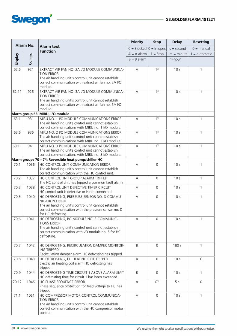
62:6 921 EXTRACT AIR FAN NO. 2A I/O MODULE COMMUNICA-TION ERRORThe air handling unit's control unit cannot establish correct communication with extract air fan no. 2A I/O module.
A 13) 10 s 1
62:11 926 EXTRACT AIR FAN NO. 3A I/O MODULE COMMUNICA-TION ERRORThe air handling unit's control unit cannot establish correct communication with extract air fan no. 3A I/O module.
A 13) 10 s 1
Alarm group 63: MIRU, I/O module63:1 931 MIRU NO. 1 I/O MODULE COMMUNICATIONS ERROR
The air handling unit’s control unit cannot establish correct communications with MIRU no. 1 I/O module.
A 13) 10 s 1
63:6 936 MIRU NO. 2 I/O MODULE COMMUNICATIONS ERRORThe air handling unit’s control unit cannot establish correct communications with MIRU no. 2 I/O module.
A 13) 10 s 1
63:11 941 MIRU NO. 3 I/O MODULE COMMUNICATIONS ERRORThe air handling unit’s control unit cannot establish correct communications with MIRU no. 3 I/O module.
A 13) 10 s 1
Alarm groups 70 – 74: Reversible heat pump/chiller HC70:1 1036 HC CONTROL UNIT COMMUNICATION ERROR
The air handling unit's control unit cannot establish correct communication with the HC control unit.
A 0 10 s 1
70:2 1037 HC CONTROL UNIT GROUP ALARM TRIPPEDThe HC control unit has tripped a common fault alarm
A 0 10 s 1
70:3 1038 HC CONTROL UNIT DEFECTIVE TIMER CIRCUITHC control unit is defective or is not connected.
A 0 10 s 1
70:5 1040 HC DEFROSTING, PRESSURE SENSOR NO. D COMMU-NICATION ERRORThe air handling unit's control unit cannot establish correct communication with the pressure sensor no. D for HC defrosting.
A 0 10 s 1
70:6 1041 HC DEFROSTING, I/O MODULE NO. 5 COMMUNIC-TIONS ERRORThe air handling unit’s control unit cannot establish correct communication with I/O module no. 5 for HC defrosting.
A 0 10 s 1
70:7 1042 HC DEFROSTING, RECIRCULATION DAMPER MONITOR-ING TRIPPEDRecirculation damper alarm HC defrosting has tripped.
B 0 180 s 1
70:8 1043 HC DEFROSTING, EL. HEATING COIL TRIPPEDElectric air heating coil alarm HC defrosting has tripped.
A 0 10 s 0
70:9 1044 HC DEFROSTING TIME CIRCUIT 1 ABOVE ALARM LIMITHC defrosting time for circuit 1 has been exceeded.
B 0 10 s 1
70:12 1046 HC PHASE SEQUENCE ERRORPhase sequence protection for feed voltage to HC has tripped.
A 03) 5 s 0
71:1 1051 HC COMPRESSOR MOTOR CONTROL COMMUNICA-TION ERRORThe air handling unit's control unit cannot establish correct communication with the HC compressor motor control.
A 0 10 s 1

www.swegon.com 21We reserve the right to alter specifications without notice.
GB.GOLDSKFLARM.181221
Alarm No. Alarm textFunction
Priority Stop Delay Resetting
0 = Blocked 0 = In oper. s = second 0 = manual
Dis
pla
y
Co
mm
. A = A alarm 1 = Stop m = minute 1 = automatic
B = B alarm h=hour
71:2 1052 HC COMPRESSOR MOTOR CONTROL START-UP FAIL-UREThe compressor motor does not rotate during start up.
A 0 10 s 1
71:3 1053 HC COMPRESSOR MOTOR CONTROL OVER OR UNDER VOLTAGELow or high power supply to compressor motor con-trol.
A 0 10 s 1
71:4 1054 HC COMPRESSOR OUTSIDE WORKING RANGEHC compressor works outside its ordinary working range.
A 0 10 s 1
71:9 1059 HC EXPANSION VALVE CONTROL CIRCUIT 1 COMMU-NICATION ERRORThe air handling unit's control unit cannot establish correct communication with the HC expansion valve control circuit 1.
A 0 10 s 1
72:1 1066 HC HIGH PRESSURE MONITOR CIRCUIT 1 TRIPPEDThe high pressure monitor alarm HC circuit 1, has tripped.
A 0 10 s 1
72:2 1067 HC HIGH PRESSURE CIRCUIT 1 ABOVE ALARM LIMITThe high pressure alarm HC circuit 1, has tripped.
A 0 10 s 1
72:3 1068 HC THERMOSTATIC CONTACT CIRCUIT 1 TRIPPEDThe thermostatic contacts alarm HC circuit 1, has tripped.
A 0 10 s 1
72:4 1069 HC HOT GAS TEMPERATURE CIRCUIT 1 ABOVE ALARM LIMITThe hot gas temperature alarm HC circuit 1, has tripped.
A 0 10 s 1
72:5 1070 HC HOT GAS TEMPERATURE CIRCUIT 1 DEFECTIVEHot gas temperature sensor is defective or is not con-nected.
A 0 10 s 1
72:6 1071 HC HIGH PRESSURE SENSOR CIRCUIT 1 DEFECTIVEHigh pressure sensor HC circuit 1, is defective or is not connected.
A 0 10 s 1
72:7 1072 HC LOW PRESSURE SENSOR CIRCUIT 1 DEFECTIVELow pressure sensor HC circuit 1, is defective or is not connected.
A 0 10 s 1
72:8 1073 HC SUCTION GAS TEMPERATURE CIRCUIT 1 DEFEC-TIVESuction gas line temperature sensor HC circuit 1, is defective or is not connected.
A 0 10 s 1
72:9 1074 HC PRESSURE DIFFERENCE CIRCUIT 1 BELOW ALARM LIMITThe pressure difference HC circuit 1, has tripped.
A 0 10 s 1
72:10 1075 HC SERVICE OF CIRCUIT 1 AND COMPRESSORService of circuit 1 and compressor required.
A 0 10 s 1
72:11 1076 HC OVERHEATING TEMPERATURE CIRCUIT 1 BELOW ALARM LIMITHC overheating temperature circuit 1 falls below the set alarm limit.
A 0 10 s 1
72:12 1077 HC PRESSURE EQUALISATION OF LOW PRESSURE CIRCUIT 1HC pressure equalisation low pressure circuit 1, has tripped.
A 0 10 s 1

22 www.swegon.com We reserve the right to alter specifications without notice.
GB.GOLDSKFLARM.181221
Alarm No. Alarm textFunction
Priority Stop Delay Resetting
0 = Blocked 0 = In oper. s = second 0 = manual
Dis
pla
y
Co
mm
. A = A alarm 1 = Stop m = minute 1 = automatic
B = B alarm h=hour
72:13 1078 HC PRESSURE EQUALISATION OF HIGH PRESSURE CIRCUIT 1HC pressure equalisation high pressure circuit 1, has tripped.
A 0 10 s 1
72:14 1079 HC LOW PRESSURE CIRCUIT 1 BELOW ALARM LIMITHC low pressure circuit 1 falls below the set alarm limit.
A 0 10 s 1
Alarm group 77 – 79: MIRU, motor controllers77-79:2
1142, 1157, 1172
MIRU NO. 1-3 MOTOR CONTROLLER OVERCURRENTMotor controller for roof ventilator MIRUVENT has registered excessively high current to the drive motor.
A 0 10 s 0
77-79:3
1143, 1158, 1173
MIRU NO. 1-3 MOTOR CONTROLLER UNDERVOLTAGELow supply voltage to the roof ventilator MIRUVENT’s motor controller.
A 0 60 sec. 0
77-79:4
1144, 1159, 1174
MIRU NO. 1-3 MOTOR CONTROLLER OVER VOLTAGEHigh supply voltage to the roof ventilator MIRUVENT’s motor controller.
A 0 10 s 0
77-79:5
1145, 1160, 1175
MIRU NO. 1-3 MOTOR CONTROLLER OVER TEMPERA-TUREHigh internal temperature.
A 0 10 s 0
77-79:6
1146, 1161, 1176
MIRU NO. 1-3 MOTOR CONTROLLER START-UP FAIL-UREDrive motor does not rotate during start up.
A 0 10 s 0
77-79:7
1147, 1162, 1177
MIRU NO. 1-3 MOTOR CONTROLLER UNEVEN PHASE VOLTAGEHigh voltage difference between the phases (3-phase, 400 V), which causes rippling.
A 0 10 s 1
77-79:8
1148, 1163, 1178
MIRU NO. 1-3 MOTOR CONTROLLER PHASE ERRORPhase failure in motor controller.
A 0 10 s 1
77-79:9
1149, 1164, 1179
MIRU NO. 1-3 MOTOR CONTROLLER INTERNAL MEMORY ERRORInternal memory error in motor controller.
A 0 10 s 1
77-79:10
1150, 1165, 1180
MIRU NO. 1-3 MOTOR CONTROLLER CURRENT LIMITA-TIONCurrent/Voltage limitation in motor controller.
A 0 60 sec. 1
77-79:11
1151, 1166, 1181
MIRU NO. 1-3 MOTOR CONTROLLER INTERNAL COM-MUNICATIONS ERRORInternal communication error in motor controller.
A 0 10 s 1
Alarm group 81 – 84: SMART Link, supply air flow81-84:2
1202, 1217, 1232, 1247
SMART LINK NO. 1-4 SUPPLY AIR FLOW BELOW DEFROSTING ALARM LIMITThe alarm for supply air flow below defrosting alarm limit has tripped.
A 0 70 m 1
81- 84:3
1203, 1218, 1233, 1248
SMART LINK NO. 1-4 HIGH PRESSURE MONITOR TRIPPEDThe high pressure monitor alarm has tripped.
A 0 30 s 1
81- 84:4
1204, 1219, 1234, 1249
SMART LINK NO. 1-4 HIGH PRESSURE ABOVE ALARM LIMITThe high pressure sensor measures higher pressure than preset alarm limit pressure.
A 0 30 s 1
81- 84:5
1205, 1220, 1235, 1250
SMART LINK NO. 1-4 LOW PRESSURE BELOW ALARM LIMITThe low pressure sensor measures lower pressure than preset alarm limit pressure.
A 0 30 s 1

www.swegon.com 23We reserve the right to alter specifications without notice.
GB.GOLDSKFLARM.181221
1) Cannot be blocked.2) The delay is adjustable.3) Adjustable.4) Stops the AHU if the temperature is below the adjustable limit.5) Inactive as factory setting.6) Contact Swegon or their representative.7) Alarm group 38 = MIRU Control 1. Alarm group 39 = MIRU Control 2. Alarm group 40 = MIRU Control 3. Alarm group 41 = MIRU Control 4. Alarm group 42 = MIRU Control 5. Alarm group 43 = MIRU Control 6. Alarm group 44 = MIRU Control 7. Alarm group 45 = MIRU Control 8. Alarm group 46 = MIRU Control 9. Alarm group 47 = MIRU Control 10.8) Alarm group 49 = Supply air fan 1A. Alarm group 50 = Supply air fan 2A. Alarm group 51 = Supply air fan 3A. Alarm group 52 = Supply air fan 1B. Alarm group 53 = Supply air fan 2B. Alarm group 54 = Supply air fan 3B.9) Alarm group 55 = Extrat air fan 1A. Alarm group 56 = Extrat air fan 2A. Alarm group 57 = Extrat air fan 3A. Alarm group 58 = Extrat air fan 1B. Alarm group 59 = Extrat air fan 2B. Alarm group 60 = Extrat air fan 3B.
Alarm No. Alarm textFunction
Priority Stop Delay Resetting
0 = Blocked 0 = In oper. s = second 0 = manual
Dis
pla
y
Co
mm
. A = A alarm 1 = Stop m = minute 1 = automatic
B = B alarm h=hour
81- 84:6
1206, 1221, 1236, 1251
SMART LINK NO. 1-4 EVAPORATION TEMPERATURE BELOW ALARM LIMITThe evaporation temperature drops below the preset alarm limit for more than 30 seconds.
A 0 30 s 1
81- 84:7
1207, 1222, 1237, 1252
SMART LINK NO. 1-4 GROUP ALARM FREQUENCY CONVERTER The frequency converter has tripped a group alarm
A 0 30 s 1
81- 84:8
1208, 1223, 1238, 1253
SMART LINK NO. 1-4 OUTSIDE WORKING RANGESMART Link works outside its ordinary working range.
A 0 30 s 1
81- 84:9
1209, 1224, 1239, 1254
SMART LINK NO. 1-4 COMPRESSOR, START-UP FAIL-UREThe compressor motor does not rotate during start up.
A 0 30 s 1
81- 84:10
1210, 1225, 1240, 1255
SMART LINK NO. 1-4 HOT GAS TEMPERATURE ABOVE ALARM LIMITHot gas temperature has exceeded the alarm limit.
A 0 30 s 1
81- 84:11
1211, 1226, 1241, 1256
SMART LINK NO. 1-4 PRESSURE DIFFERENCE BELOW ALARM LIMITThe pressure difference drops below the preset alarm limit for more than 30 seconds.
A 0 30 s 1

24 www.swegon.com We reserve the right to alter specifications without notice.
GB.GOLDSKFLARM.181221
2. Information MessagesInformation messages are displayed in the hand-held terminal. Information messages are displayed only when the terminal is in the Dashboard image.
Message No. Message text
96:1 HC DEFROSTING CALIBRATION NOT PERFORMED HC defrosting calibration cannot be performed.
96:2 HC DEFROSTING CALIBRATION NOT APPROVEDHC defrosting calibration is performed, but read values are not approved.
96:3 HC LIMIT FOR SUPPLY AIR FLOW IS BELOW THE FACTORY SETTINGThe set limit for the supply air flow is below the factory setting that permits HC operation.
96:4 HC LIMIT FOR EXTRACT AIR FLOW IS BELOW THE FACTORY SETTINGThe set limit for the extract air flow is below the factory setting that permits HC operation.
96:5 HC OUTDOOR TEMPERATURE LIMIT FOR HEATING BELOW THE FACTORY SETTINGThe set limit for the outdoor air temperature is below the factory setting that permits HC operation.
97:12 PLATE HEAT EXCHANGER, BYPASS OPTIMIZATION NOT PERFORMEDBypass optimization of plate heat exchanger cannot be performed.
97:13 PLATE HEAT EXCHANGER, BYPASS OPTIMIZATION FAILUREBypass optimization of the plate heat exchanger has been performed, but the readings are not satisfactory.
97:14 PLATE HEAT EXCHANGER DEFROSTING CALIBRATION NOT PERFORMEDDefrosting calibration of the plate heat exchanger cannot be performed.
97:15 PLATE HEAT EXCHANGER DEFROSTING CALIBRATION FAILUREDefrosting calibration of the plate heat exchanger has been performed, but the readings are not satisfactory.
98:1 SUPPLY AIR PRE-FILTER CALIBRATION NOT PERFORMEDPre-filter calibration, supply air, not performed after first start. Recurrent at 30 minute intervals. The message is not received after completed filter calibration.
98:2 SUPPLY AIR PRE-FILTER CALIBRATION FAILUREPre-filter calibration failure, supply air. Recurrent at 5 second intervals.
98:3 EXTRACT AIR PRE-FILTER CALIBRATION NOT PERFORMEDPre-filter calibration, extract air, not performed after first start. Recurrent at 30 minute intervals. The message is not received after completed filter calibration.
98:4 EXTRACT AIR PRE-FILTER CALIBRATION FAILUREPre-filter calibration failure, extract air. Recurrent at 5 second intervals.
98:5 SUPPLY AIR AHU FILTER CALIBRATION NOT PERFORMEDsupply air AHU filter calibration, supply air, not performed after first start. Recurrent at 30 minute intervals. The message is not received after completed filter calibration.
98:6 SUPPLY AIR AHU FILTER CALIBRATION FAILUREAHU filter calibration failure, supply air. Recurrent at 5 second intervals.
98:7 EXTRACT AIR AHU FILTER CALIBRATION NOT PERFORMEDAHU filter calibration, extract air, not performed after first start. Recurrent at 30 minute intervals. The message is not received after completed filter calibration.
98:8 EXTRACT AIR AHU FILTER CALIBRATION FAILUREAHU filter calibration failure, extract air. Recurrent at 5 second intervals.
98:9 SUPPLY AIR END FILTER CALIBRATION NOT PERFORMEDEnd filter calibration, supply air, not performed after first start. Recurrent at 30 minute intervals. The message is not received after completed filter calibration.
98:10 SUPPLY AIR END FILTER CALIBRATION FAILUREEnd filter calibration failure, supply air. Recurrent at 5 second intervals.
98:11 ROTARY HEAT EXCHANGER DEFROSTING CALIBRATION NOT PERFORMEDDefrost calibration, rotary heat exchanger, not performed after function was activated for first time. Recurrent at 30 minute intervals. The message is not received after completed heat exchanger calibration.
Information messages provide information e.g. about necessary settings that have not been entered or unfavourable operating conditions.The information message is indicated by a blue circle in the alarm log button on the instrument panel.

www.swegon.com 25We reserve the right to alter specifications without notice.
GB.GOLDSKFLARM.181221
Ala
rm N
o. Alarm text
Function
98:12 ROTARY HEAT EXCHANGER DEFROSTING CALIBRATION FAILUREDefrost calibration failure, rotary heat exchanger. Recurrent at 5 second intervals.
98:13 ReCO2 CALIBRATION NOT PERFORMEDReCO2 calibration not performed after function was activated for first time. Recurrent at 30 minute intervals. Message is not received after completed ReCO2 calibration.
98:14 ReCO2 CALIBRATION FAILUREReCO2 calibration failure. Recurrent at 5 second intervals.
98:15 ReCO2 WRONG SETTINGPressure regulation, slave control or wrong type of AHU is selected. Recurrent at 5 second intervals.
99:1 E-MAIL ERRORError when sending e-mail. The message is received after ten tries.
99:5 FTP ERRORError when sending to ftp. The message is received after ten tries.
99:7 SD SHORT MEMORY SOON FULLThe SD card's memory is soon full. The oldest log data will sonn be deleted. Factory default Off.
99:8 SD SHORT MEMORY FULLThe SD card's memory is full. The oldest log data is being deleted. Factory default Off.
99:11 NO EXTERNAL OUTDOOR TEMPERATURE SENSOR CONNECTED FOR HEAT-RETAINING FUNCTIONTemperature sensor for heat-retaining function is not fitted or is not connected correctly.
99:14 INTERNAL SERIAL MEMORY ERROR CPEx1Internal serial memory error CPEx1
99:15 CLOCK CIRCUIT DEFECTIVECircuit for the clock is defective

26 www.swegon.com We reserve the right to alter specifications without notice.
GB.GOLDSKFLARM.181221