goals of dva-1 meeting overall goal: build an ska antenna with ska feeds/receivers, verify...
Post on 20-Dec-2015
215 views
TRANSCRIPT
Goals of DVA-1 Meeting• Overall goal: build an SKA antenna with SKA feeds/receivers,
verify performance and fabrication/costs for the next stages of the SKA
• Project description and definition– purpose and scope– cost– schedule
• Partnership– resources (in-kind, cash)
• Management – as in MoU draft?
• Technical decisions• Program/project decisions
15-16 April 2010 DVA1 Meeting at NSF 1

Technical Decisions• Required technical specifications• Aperture size (12m – 15m)• Optics (offset gregorian): shaping?• Backup structure: spars, shell• Pedestal type• Feed and receiver plan
– SPFs– PAFs– Indexer
15-16 April 2010 DVA1 Meeting at NSF 2

Program/Project Decisions• Management plan and MoU/LoI• Schedule
– milestones (TDP, PrepSKA, SKA program)– deliverables (hardware test results, reports)
• Site– which facility and where on site?
• Testing program– single dish tests:
• those necessary for the costed system by end-2012• those needed for antennas program leading to the Phase-I dish array
– interferometric tests not within timeline/scope of end-2012 project
15-16 April 2010 DVA1 Meeting at NSF 3
Scope of the DVA-1 Project
• The first in a series of converging prototypes that will optimize performance at minimum cost (e.g. A/T per dollar + imaging performance)
• A primary deliverable of the US SKA TDP– optimized antenna + feeds for SKA-mid– WBSPFs and PAFs accommodated
• A global project but centered in North America• Delivered to the project by end of 2012 (including testing)• Current plan (to be agreed on):
– fabrication, integration and testing at EVLA site by end of 2012 to provide input to the costed system design
– single-dish tests with suite of feeds – extended testing program as needed for lead-up to Phase-I
construction (with post-TDP, post-PrepSKA funding)
15-16 April 2010 DVA1 Meeting at NSF 4
Overall Context in TDP• System cost
• Costs that scale with N (antennas, feeds)• Processing costs that scale as N2 x number of beams
• Maximize A/T per antenna in a low-cost design• minimizes number of antennas needed for total A/T• also maximizes survey speed via the (A/T)2 factor
• Target high imaging dynamic range and minimum susceptibility to RFI (clear aperture)
• Demonstrate imaging capability through simulation by Calibration and Processing Group et al. using as input measurements on DVA-1
15-16 April 2010 DVA1 Meeting at NSF 5
Basic specifications• Offset Gregorian optics• Frequency range: 0.3 to 10 GHz (1 to 10 GHz)• Aperture efficiency: >60% above 1 GHz• Antenna noise temperature <10K• Pointing stability: <1% gain variation @half-power point
at 1.4 GHz• Minimum 30 year lifetime• Minimum 1 year maintenance interval (target 5 year)• Design to be as close as possible to the final SKA dish
design– Assessment of real performance– Good cost estimate
15-16 April 2010 DVA1 Meeting at NSF 6

Optical design of reflectors
Working plan:
• Dual shaped, offset reflectors with a Gregorian subreflector.
• Subreflector opening angle chosen to accommodate wide band feed(s).
• Shaped optics having very low spillover and high aperture efficiency to maximize A/T in a design intended to minimize costs
• Usage of available real estate for multiple feeds and a PAF; DVA-1 will include a feed indexer
15-16 April 2010 DVA1 Meeting at NSF 7

Reflector design options
Single composite shell and sparse support framing
Dual shell reflector and support, composites
15-16 April 2010 8DVA1 Meeting at NSF
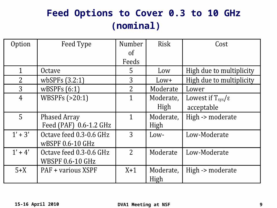
Feed Options to Cover 0.3 to 10 GHz (nominal)
15-16 April 2010 9DVA1 Meeting at NSF

Canadian CART program + TDP Work by Matt Fleming:
15-16 April 2010 10DVA1 Meeting at NSF
Issues and Decisions• Diameter: 15m nominal (12m still possible as a choice)• Optical design: offset Gregorian optics
– rationale for shaped optics in TDP Memo (in prep)– final choice depends on assessment of imaging performance and
long-term flexibility as well as optimized A/T @ minimum cost• Fabrication material
– dual-shell composite vs composite + metal spar structure– (segmented metal is a possible parallel approach)
• Full suite of TDP-developed feed antennas that cover 0.3 to 10 GHz– various combinations of WBSPFs and octave feeds– antenna will accommodate a PAF when appropriate
• Feed indexer included in design with deployment at appropriate phase of testing
15-16 April 2010 11DVA1 Meeting at NSF
Developing DVA-1 Partnership• Cornell/TDP
– Optical design: Baker, Cortes, Imbriale (JPL)– WBSPFs:
• Cortes (Cornell)• Weinreb (Caltech)• Welch (UCB)
– Mechanical design: Fleming (Minex)– Calibration and Processing: Kemball (UIUC) et al
• DRAO (CART program for composite reflector)– G. Lacy (mechanical, composites)– G. Hovey– S. Dougherty
• SPDO– N. Roddis and P. Dewdney
• NRAO– Project management and integration with EVLA
• Australia/CASS• China/JLRAT• South Africa/MeerKAT• Testing:
– single dish tests by TDP team + other partners– array tests: in 2012+ post-preparatory/engineering design phase
15-16 April 2010 DVA1 Meeting at NSF 12

Management of DVA-1To be agreed upon:
• Project Manager
• Project Engineer
• Collaboration Board (Cornell, DRAO, NRAO, SPDO, …) – determined by groups that sign on to the project
• DVA-1 design reviews– coordinated with (but separate from) SPDO design
reviews
15-16 April 2010 DVA1 Meeting at NSF 13
DVA Context&
DVP Goals
P. DewdneyApr 15, 2010
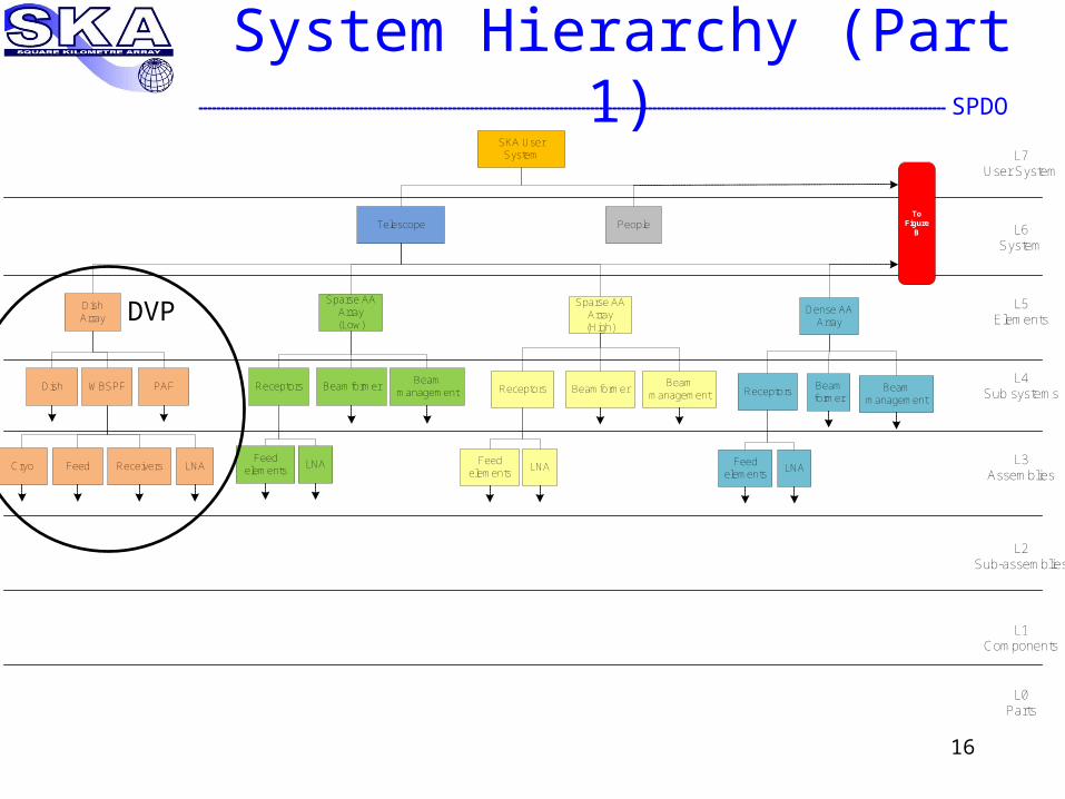
SPDOSystem Hierarchy (Part 1)
16
Telescope
Dish WBSPF
Receivers
SKA User System
Dish Array
Sparse AAArray (Low)
Dense AAArray
Receptors
Feed elements
LNA
People L6System
L7User System
L5Elements
L4Sub systems
L3Assemblies
L2Sub-assemblies
L1Components
Beamformer
Cryo Feed
L0Parts
PAF
LNA
Receptors
Feed elements
LNA
Beam former
Beam management
Beam management
Sparse AAArray (High)
Receptors
Feed elements
LNA
BeamformerBeam
management
To Figure
B
DVP

SPDO
System Hierarchy (Part 2)
17
Facilities L6System
L7User System
L5Elements
L4Sub systems
L3Assemblies
L2Sub-assemblies
L1Components
L0Parts
Power Infra-structure
STaN
Operations and Maintenance
Centre(s)
Regional Centres
Regional Engineering
Centres
Core site
Central site
Off site
SupportVisitor centre
Support HQSupport
Trenches RoadsAntenna
foundations
Core site
Central site
Outlying stations
Core site
Central site
Outlying stations
Water FencesGrid Backup Alternative Stores Workshops Offices
Computing and Software
From Figure
A
Signal Processing
Facility
SignalProc
Channeliser and
Correlator
Non visibility
processor
SPDO• Process to verify performance of dishes for the Dish
Array in the System Hierarchy.– Element level.
• Dishes equipped with well defined interfaces to other system elements:– Power– Signal transport– Monitor and Control – Other infrastructure
• Verified to be capable of handling all feeds and receivers needed to carry out the dish-based science.– May not be so-equipped at initial roll-out.
Dish Verification Program (DVP)
18
SPDO• Risk reduction
– When built up into the SKA system, show that dishes will meet all the science requirements;
– Also meet all other requirements needed to integrate into a system and operate in the field.
• Design, produce and test one or more SKA antennas;– with the greatest system sensitivity (Ae/Tsys and/or Survey Speed) per
unit system cost (total cost of ownership);– As well as possible, ensure that the contribution of antenna-related
systematic errors is within acceptable limits;
– Designs/testing programs converging to a detailed design that is
manufacturable in production quantities.
• Understand the costs.• Converge to a production-ready, documented antenna
design (production data-pack).
DVP Goals
19

SPDO
Integrated Approach
20
SKA Science Case
DRM Analysis
ConceptsMemo 100
Risk Management
Plan
Technologies
DRM
Requirements DevelopmentAnalysis Validation
Risk mitigation strategies and projectsVerification programmes (DVP, AAVP, other domains), Design studies, Precursors, Pathfinders
PDR
Selections for reference designRisks
System Definition Phase System Prelim Design Phase
DesignFunctional analysis, verification and synthesisDesign verification
High level requirements
SRR
CODR
Requirements (Development, Analysis , Validation)PDR
Definition Phase Prelim Design Phase
Design (Functional analysis, verification and synthesis, Design verification)
SRR
Concept Phase
Concepts
CODR
ELEMENTS
Concept Phase
SYSTEM
RISK MANAGEMENT
Tradeoffs
Tradeoffs
RisksDVAs

SPDO
Time Scale
21
PreliminaryDesign
Concept definition Sub-System DefinitionDetailedDesign Site Assembly, Integration and Testing
CoDR
Preliminary Design
CoDR SRR PDR
rep
ortRFI Monitoring
Site Acceptance tests including RFI qualificationSite
Engineering
Dishes
Signal Processing
Imaging ConceptSoftware Requirements DefinitionPreliminary high level architecture
On-site TestingPhase 1 Refinement and Roll-out
CoDR PDR
Software & Computing
Signal transport & Networks
Concept Definition Dishes, AAs
Dish Sub-Sys. Definition
DVA1Dish Prototype
Fabrication
DVA1Prototype Dish Testing
Site Assembly, Integration and Testing
2009 2010 2011 2012 2013 2014 2015 2016 2017 2018
Prototype AAVS1 Testing
SRR PDR
Sub-System Definition
CoDR PDR CDR
CDR
RQZSite characteristicsAtmospheric studiesConfiguration studies
CDR
Milestones
Baseline design for Phase 1
Site decision Costed system design
AA Sub-Sys. Definition
AA Prototype Fabrication
2009 2010 2011 2012 2013 2014 2015 2016 2017 2018
Remote Station Land Acquisition & Environmental Studies
Continued RFI and Tropo Monitoring
Temporary Software Correlator
Phase 2 Continuation
Phase 2 Continuation
Phase 2 Continuation
Phase 2 Continuation
Phase 2 Continuation
S/W Development & Roll-out for Phase 2
Baseline design for Phase 2
Phase 2 Correlator Design
Monitoring & Control
Data Storage
CDR PR
CDR PR
SRR
Hardware Correlator Early Fabrication
PRFactory Assembly, Integration and Testing
Site Assembly, Integration and Testing
SRR
PDR
Front End and Channeliser
Beamformer and Correlator
Pulsar and Transient Processor
Start of Phase 2
Construction
Phase 2 …..
Phase 1 Construction, Verification, Commissioning, Acceptance, Integration & First Science
Detailed Design, Prod. Eng& Tooling
SKA Preparatory Phase
Refine high level architecturePreliminary Design
Ops and Maintenance Facility
Tooling and Early Fabrication
Purchase or Fabrication
Detailed Design
Detailed Design, Coding, Integration with platforms and testing
Central Data Processing Facility
Science Computing Facility
Start of Phase 1 Construction
Factory Assembly, Integration and Testing
Factory Assembly, Integration and Testing
Rev 7a2010-04-13
Definition and DesignPhase 1 System Testing
SRR
System Engineering
CoDRPhase 1 Systems integration
PDR CDR
Phase 1 Verification and CommisioningSystem refinement, change management
Final SKA Deployment PlanProject management
PM Plan &
Schedule
SKA Scope definitionPrepSKA Plan Project staffing & developmentWBS, resource allocation
CoDR PDR CDR
REV REV
Science DRM Development
Revision of Science Case
REV
Refinement of Early Science Shared Risk Science Operations
REVPhase 2 Science Development
REV REV
Science / Engineering tradeoffs
Early Science Proposals
Continued System Engineering for Phase 2
Continuous Performance Evaluation
Project execution, monitor and control
Infrastructure Detailed Design (fibre & power)
Antenna Foundations and Trenching Roll out
Phase 1 construction
approval
Infrastructure Detailed Design (buildings)
CDR
Concept Definition AAsAperture Arrays
DVA2 development and testing
AAVS2 development and testing AAVS2 demo
PDRSRRCoDR CDR
DVPReview dates are preliminary.

SPDO
Time Scale
22
Review dates are preliminary.
CoDR
Dishes Concept Definition
Dish Sub-Sys. Definition
DVA1 Prototype Fabrication
DVA1Prototype Testing
2009 2010 2011 2012 2013 2014 2015 2016
SRR PDR
Milestones
Baseline design for Phase 1
Site decision Costed system design
2009 2010 2011 2012 2013 2014 2015 2016
CDR PR
Phase 1 Construction
Detailed Design, Prod. Eng& Tooling
SKA Preparatory Phase
Tooling and Early Fabrication
Start of Phase 1 Construction
Rev 7a2010-04-13
Phase 1 construction
approval
DVA2 development and testing

End23

Extra
15-16 April 2010 DVA1 Meeting at NSF 24
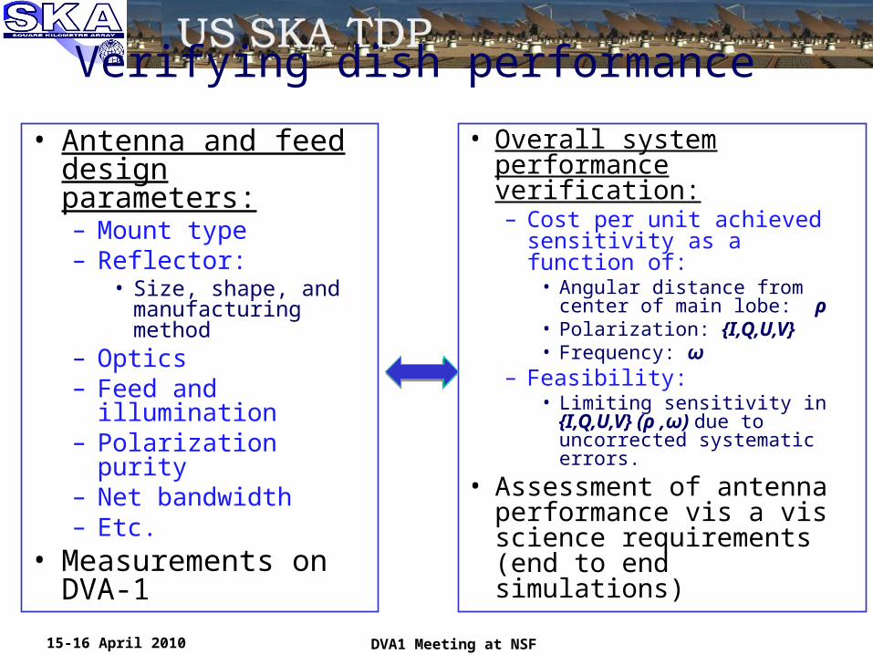
Verifying dish performance
• Antenna and feed design parameters:– Mount type– Reflector:
• Size, shape, and manufacturing method
– Optics– Feed and illumination– Polarization purity– Net bandwidth– Etc.
• Measurements on DVA-1
• Overall system performance verification:– Cost per unit achieved
sensitivity as a function of:• Angular distance from center
of main lobe: ρ• Polarization: {I,Q,U,V}• Frequency: ω
– Feasibility:• Limiting sensitivity in
{I,Q,U,V} (ρ ,ω) due to uncorrected systematic errors.
• Assessment of antenna performance vis a vis science requirements (end to end simulations)
15-16 April 2010 DVA1 Meeting at NSF

15-16 April 2010 DVA1 Meeting at NSF 26
• Optical design of reflectors.Dual shaped, offset reflectors with a Gregorian subreflector.Subreflector opening angle chosen to accommodate wide band feed(s).Shaped optics having very low spillover and high aperture efficiency.Incorporation of “real estate” for multiple feeds and a PAF.
• Light weight, optimized mechanical design
Utilization of single shell reflectors as integral structural members.Inclusion of a feed indexer to mount multiple feeds.Design for low cost in mass production.
• Mount and test multiple feeds and receivers.
Optics designed to accommodate feeds of intermediate gain which achieves a practical primary reflector size. • Basic specifications:
Frequency range: .3 to 10 GHz.Aperture efficiency: >60%Antenna noise temperature <10KPointing stability: <1% gain variation @ ½ power point (1.4 GHz.)Minimum 30 year lifetimeMinimum 1 year maintenance interval (target 5 year)
•
15-16 April 2010 DVA1 Meeting at NSF 27

15-16 April 2010 DVA1 Meeting at NSF 28

Meeting Motivations and Outcomes• NSF review of TDP and DVA plan forthcoming
• Overall timelines for SKA, TDP and PrepSKA
• Readiness for convergence in D&D
• Parallel development plan for SKA antennas– DVA-1, DVA-2 …– Large volume manufacturing options and costs
• conventional, composites, hydroforming
• SKA project decision tree over next 5yr– tradeoffs between science, costs and schedule
15-16 April 2010 DVA1 Meeting at NSF 29
DVA-1 Project Book• Purpose of DVA-1
– Relationship to DVA-2• How it fits into overall DVP activity• Technical description
• Reflectors• Backup structure• Pedestal• Indexer• Feeds and receivers• Interface to EVLA network and correlator
• Test site (and reflector fab)• Testing plan and elements
• single-dish tests• array tests
• Decommissioning of DVA-1• Detailed schedule• Management
• Organizations, Personnel and Org chart• Funding and funding profile• MoA or MoU?
15-16 April 2010 DVA1 Meeting at NSF 30