gn1300 manual 20130711 - smithy operator's...granite 1300 series combination lathe/mill/drill...
TRANSCRIPT

GRANITE 1300 SERIESCOMBINATION LATHE/MILL/DRILL
OPERATOR’S MANUALUpdated April, 2008
170 Aprill Dr., Ann Arbor, MI, USA 48103 Toll Free 1-800-476-4849
www.smithy.com

© 2008 Smithy Co. All rights reserved (Revision 3).
170 Aprill Dr., Ann Arbor, Michigan, USA 48103 Toll Free Hotline: 1-800-476-4849
Fax: 1-800-431-8892 International: 734-913-6700 International Fax: 734-913-6663
All images shown are from Granite Classic 1324 model.All other images for other Granite models are specified.
All rights reserved. No part of this manual may be reproduced or transmitted in any form by any means, electronic, mechanical, photocopying, recording, or otherwise, without prior written permission of Smithy Co. For information on getting permission for reprints and excerpts, comments, or suggestions, contact [email protected]
While every precaution has been taken in the preparation of this manual, Smithy Co. shall nothave any liability to any person or entity with respect to any loss or damage caused or alleged to be caused directly or indirectly by the instructions contained in this manual.Please see section on warranty and safety precautions before operating the machine.
Printed and bound in the United States of America.
Table of Contents
Chapter 1: Introduction
Welcome . . . . . . . . . . . . . . . . . . . . . . . . . . . . . . . . . . . . . . . . . . . . . . . . .1-1Contact Information and Customer Information . . . . . . . . . . . . . . . .1-2
Chapter 2: Safety
Overview . . . . . . . . . . . . . . . . . . . . . . . . . . . . . . . . . . . . . . . . . . . . . . . . .2-1Symbols Used in this Manual . . . . . . . . . . . . . . . . . . . . . . . . . . . . . . .2-1Shop Safety Rules . . . . . . . . . . . . . . . . . . . . . . . . . . . . . . . . . . . . . . . . .2-2Machine Safety Rules . . . . . . . . . . . . . . . . . . . . . . . . . . . . . . . . . . . . . .2-3
Chapter 3: Inventory Check List
Overview . . . . . . . . . . . . . . . . . . . . . . . . . . . . . . . . . . . . . . . . . . . . . . . . .3-1Items Mounted to your machine . . . . . . . . . . . . . . . . . . . . . . . . . . . . .3-1Items Packed in the larger Smithy Box . . . . . . . . . . . . . . . . . . . . . . .3-2Items Packed in smaller Smity Box . . . . . . . . . . . . . . . . . . . . . . . . . .3-4Items Packed in Plastic Bag . . . . . . . . . . . . . . . . . . . . . . . . . . . . . . . .3-5Additional Items for GN-IMX Series . . . . . . . . . . . . . . . . . . . . . . . . . .3-5
Chapter 4: Machine Overview
Overview . . . . . . . . . . . . . . . . . . . . . . . . . . . . . . . . . . . . . . . . . . . . . . . . .4-1Major Features Identified . . . . . . . . . . . . . . . . . . . . . . . . . . . . . . . . . . .4-1Millhead Components and Functions . . . . . . . . . . . . . . . . . . . . . . . . .4-3Powerhead Components and Functions . . . . . . . . . . . . . . . . . . . . . .4-5Pulley Box . . . . . . . . . . . . . . . . . . . . . . . . . . . . . . . . . . . . . . . . . . . . . . . .4-7Carriage Asssembly . . . . . . . . . . . . . . . . . . . . . . . . . . . . . . . . . . . . . . .4-8Carriage Assembly - Compound Angle Toolpost . . . . . . . . . . . . . .4-11Tailstock . . . . . . . . . . . . . . . . . . . . . . . . . . . . . . . . . . . . . . . . . . . . . . . .4-12For Granite MAX and IMX Series Machine . . . . . . . . . . . . . . . . . .4-13
Chapter 5: Preparing Your Machine For Operation
Overview . . . . . . . . . . . . . . . . . . . . . . . . . . . . . . . . . . . . . . . . . . . . . . . . .5-1Assembly of Minor Components . . . . . . . . . . . . . . . . . . . . . . . . . . . . .5-1Drill Chuck and Arbor . . . . . . . . . . . . . . . . . . . . . . . . . . . . . . . . . . . . . .5-1Arbor Plug . . . . . . . . . . . . . . . . . . . . . . . . . . . . . . . . . . . . . . . . . . . . . . . .5-2Mill Spindle Cover . . . . . . . . . . . . . . . . . . . . . . . . . . . . . . . . . . . . . . . . .5-2Cleaning and Lubricating Your Machine . . . . . . . . . . . . . . . . . . . . . .5-3Lubrication Schedule . . . . . . . . . . . . . . . . . . . . . . . . . . . . . . . . . . . . . .5-3
Lubrication Points . . . . . . . . . . . . . . . . . . . . . . . . . . . . . . . . . . . . . . . . .5-3Gearbox . . . . . . . . . . . . . . . . . . . . . . . . . . . . . . . . . . . . . . . . . . . . . . . . . .5-4

Ways . . . . . . . . . . . . . . . . . . . . . . . . . . . . . . . . . . . . . . . . . . . . . . . . . . . .5-5Carriage Assembly - Saddle . . . . . . . . . . . . . . . . . . . . . . . . . . . . . . . .5-5Carriage Assembly - Cross-Slide Table . . . . . . . . . . . . . . . . . . . . . . .5-6Compound Angle Toolpost . . . . . . . . . . . . . . . . . . . . . . . . . . . . . . . . . .5-6Cross-Slide Screw . . . . . . . . . . . . . . . . . . . . . . . . . . . . . . . . . . . . . . . . .5-6Leadscrew . . . . . . . . . . . . . . . . . . . . . . . . . . . . . . . . . . . . . . . . . . . . . . . .5-7Oil Drip . . . . . . . . . . . . . . . . . . . . . . . . . . . . . . . . . . . . . . . . . . . . . . . . . . .5-7Quick Change Gearbox . . . . . . . . . . . . . . . . . . . . . . . . . . . . . . . . . . . . .5-7Tailstock Barrel . . . . . . . . . . . . . . . . . . . . . . . . . . . . . . . . . . . . . . . . . . .5-8Mill/Drill Clutch . . . . . . . . . . . . . . . . . . . . . . . . . . . . . . . . . . . . . . . . . . . .5-8
Adjusting Gibs . . . . . . . . . . . . . . . . . . . . . . . . . . . . . . . . . . . . . . . . . . . .5-9Carriage Assembly - Saddle . . . . . . . . . . . . . . . . . . . . . . . . . . . . . . . .5-9Carriage Assembly - Cross-Slide Table . . . . . . . . . . . . . . . . . . . . . .5-10Compound Angle Toolpost . . . . . . . . . . . . . . . . . . . . . . . . . . . . . . . . .5-11Tailstock . . . . . . . . . . . . . . . . . . . . . . . . . . . . . . . . . . . . . . . . . . . . . . . .5-12Adjusting Backlash . . . . . . . . . . . . . . . . . . . . . . . . . . . . . . . . . . . . . . .5-13Cross-Slide Screw . . . . . . . . . . . . . . . . . . . . . . . . . . . . . . . . . . . . . . . .5-13Cross-Slide Screw to the Front Screw Mount . . . . . . . . . . . . . . . .5-13Cross-Slide Screw to Brass Nut and Nut to the Saddle . . . . . . . .5-14Longitudinal Leadscrew . . . . . . . . . . . . . . . . . . . . . . . . . . . . . . . . . . .5-15Half-Nut to Leadscrew Backlash . . . . . . . . . . . . . . . . . . . . . . . . . . .5-16Mill Feed Backlash . . . . . . . . . . . . . . . . . . . . . . . . . . . . . . . . . . . . . . .5-16
Adjusting the fit between the Worm Gearand Pinion Gear Shaft . . . . . . . . . . . . . . . . . . . . . . . . . . . . . . . . . . . . .5-16Adjusting the fit of the Quill Gear to the Quill Rack . . . . . . . . . . . .5-17Adjusting Drive Belt Tension . . . . . . . . . . . . . . . . . . . . . . . . . . . . . . .5-19Adjusting Millhead Belt Tension . . . . . . . . . . . . . . . . . . . . . . . . . . . .5-19Adjusting Lathe Belt Tension . . . . . . . . . . . . . . . . . . . . . . . . . . . . . . .5-19Becoming Familiar with Operating Your Smithy Granite . . . . . . .5-20Running in the Lathe . . . . . . . . . . . . . . . . . . . . . . . . . . . . . . . . . . . . . .5-21Running in the Mill/Drill . . . . . . . . . . . . . . . . . . . . . . . . . . . . . . . . . . .5-22
Chapter 6: Tooling Installation
Overview . . . . . . . . . . . . . . . . . . . . . . . . . . . . . . . . . . . . . . . . . . . . . . . . .6-1Setting-up Lathe Turning . . . . . . . . . . . . . . . . . . . . . . . . . . . . . . . . . . .6-1Lathe Spindle . . . . . . . . . . . . . . . . . . . . . . . . . . . . . . . . . . . . . . . . . . . . .6-1Removing D1-4 Camlock Tooling from the Lathe Spindle . . . . . . . .6-2Installing D1-4 Camlock Tooling . . . . . . . . . . . . . . . . . . . . . . . . . . . . .6-2Installing Tailstock . . . . . . . . . . . . . . . . . . . . . . . . . . . . . . . . . . . . . . . . .6-3Installing Compond Angle Toolpost . . . . . . . . . . . . . . . . . . . . . . . . . .6-3Installing Tooling into the Compound Angle Toolpost . . . . . . . . . .6-3Setting-up Tooling in the Mill/Drill Spindle . . . . . . . . . . . . . . . . . . . .6-4Aligning Tooling . . . . . . . . . . . . . . . . . . . . . . . . . . . . . . . . . . . . . . . . . . .6-4Installing R-8 Tooling with the Drawbar . . . . . . . . . . . . . . . . . . . . . .6-4Removing R-8 Tooling from the Drawbar . . . . . . . . . . . . . . . . . . . . .6-5

Chapter 7: Manual Operations
Overview . . . . . . . . . . . . . . . . . . . . . . . . . . . . . . . . . . . . . . . . . . . . . . . . .7-1Changing Between Lathe and Mill Operation . . . . . . . . . . . . . . . . . .7-1Manual Feeding . . . . . . . . . . . . . . . . . . . . . . . . . . . . . . . . . . . . . . . . . . .7-2Mill/Drill Spindle . . . . . . . . . . . . . . . . . . . . . . . . . . . . . . . . . . . . . . . . . . .7-2Coarse Feed Operation . . . . . . . . . . . . . . . . . . . . . . . . . . . . . . . . . . . . .7-3Fine Feed Operation . . . . . . . . . . . . . . . . . . . . . . . . . . . . . . . . . . . . . . .7-3Cross-Slide Table and Carriage Assembly . . . . . . . . . . . . . . . . . . . .7-3Cross-Slide Table . . . . . . . . . . . . . . . . . . . . . . . . . . . . . . . . . . . . . . . . . .7-3Carriage Assembly . . . . . . . . . . . . . . . . . . . . . . . . . . . . . . . . . . . . . . . .7-4
Chapter 8: Speeds and Feeds
Overview . . . . . . . . . . . . . . . . . . . . . . . . . . . . . . . . . . . . . . . . . . . . . . . . .8-1Speed and Feed Rates Defined . . . . . . . . . . . . . . . . . . . . . . . . . . . . . .8-1Setting the Spindle Rotational Speed . . . . . . . . . . . . . . . . . . . . . . . .8-2High Range Speed Set-up . . . . . . . . . . . . . . . . . . . . . . . . . . . . . . . . . .8-3Mid Range Speed Set-up . . . . . . . . . . . . . . . . . . . . . . . . . . . . . . . . . . .8-3Low Range Speed Set-up . . . . . . . . . . . . . . . . . . . . . . . . . . . . . . . . . . .8-4Feed Chart Explained . . . . . . . . . . . . . . . . . . . . . . . . . . . . . . . . . . . . . .8-5Sample Settings . . . . . . . . . . . . . . . . . . . . . . . . . . . . . . . . . . . . . . . . . . .8-8
Chapter 9: Powerfeeding
Overview . . . . . . . . . . . . . . . . . . . . . . . . . . . . . . . . . . . . . . . . . . . . . . . . .9-1Powerfeeding Defined . . . . . . . . . . . . . . . . . . . . . . . . . . . . . . . . . . . . .9-1The Jog Knob . . . . . . . . . . . . . . . . . . . . . . . . . . . . . . . . . . . . . . . . . . . . .9-4Step-by-Step Lathe Powerfeeding . . . . . . . . . . . . . . . . . . . . . . . . . . .9-4Step-by-Step Mill Powerfeeding . . . . . . . . . . . . . . . . . . . . . . . . . . . . .9-5
Chapter 10: Threading
Overview . . . . . . . . . . . . . . . . . . . . . . . . . . . . . . . . . . . . . . . . . . . . . . . .10-1Leadscrew Safety Clutch Adjustment . . . . . . . . . . . . . . . . . . . . . . .10-1Basic Threading . . . . . . . . . . . . . . . . . . . . . . . . . . . . . . . . . . . . . . . . . .10-2Changing Gears . . . . . . . . . . . . . . . . . . . . . . . . . . . . . . . . . . . . . . . . . .10-3Cutting Inch Threads . . . . . . . . . . . . . . . . . . . . . . . . . . . . . . . . . . . . . .10-4Using the Threading Dial to Cut Inch Threads . . . . . . . . . . . . . . . .10-5Cutting Metric Threads . . . . . . . . . . . . . . . . . . . . . . . . . . . . . . . . . . . .10-6
Chapter 11: Machine Maintenance Schedule
Overview . . . . . . . . . . . . . . . . . . . . . . . . . . . . . . . . . . . . . . . . . . . . . . . .11-1Before Each Use . . . . . . . . . . . . . . . . . . . . . . . . . . . . . . . . . . . . . . . . .11-1After Each Use . . . . . . . . . . . . . . . . . . . . . . . . . . . . . . . . . . . . . . . . . . .11-110 Hours (Daily) . . . . . . . . . . . . . . . . . . . . . . . . . . . . . . . . . . . . . . . . . .11-225 Hours (Daily) . . . . . . . . . . . . . . . . . . . . . . . . . . . . . . . . . . . . . . . . . .11-2110 Hours (Yearly) . . . . . . . . . . . . . . . . . . . . . . . . . . . . . . . . . . . . . . . .11-2

Chapter 12: Troubleshooting
Powerfeed and Thread Cutting . . . . . . . . . . . . . . . . . . . . . . . . . . . . .12-1Carriage/Milling Table . . . . . . . . . . . . . . . . . . . . . . . . . . . . . . . . . . . .12-2Lathe Turning . . . . . . . . . . . . . . . . . . . . . . . . . . . . . . . . . . . . . . . . . . . .12-3Milling . . . . . . . . . . . . . . . . . . . . . . . . . . . . . . . . . . . . . . . . . . . . . . . . . .12-4Drilling . . . . . . . . . . . . . . . . . . . . . . . . . . . . . . . . . . . . . . . . . . . . . . . . . .12-4Drive System . . . . . . . . . . . . . . . . . . . . . . . . . . . . . . . . . . . . . . . . . . . . .12-5Motor . . . . . . . . . . . . . . . . . . . . . . . . . . . . . . . . . . . . . . . . . . . . . . . . . . .12-6Chuck and Accessories . . . . . . . . . . . . . . . . . . . . . . . . . . . . . . . . . . .12-6Leadscrew . . . . . . . . . . . . . . . . . . . . . . . . . . . . . . . . . . . . . . . . . . . . . . .12-8Granite Series Leadscrew Handwheel Fabrication and Installation . . . . . . . . . . . . . . . . . . . . . . . . . . . . . . .12-18
Chapter 13: Machine Specifications
Granite 1324 Series . . . . . . . . . . . . . . . . . . . . . . . . . . . . . . . . . . . . . . .13-1Granite 1340 Series . . . . . . . . . . . . . . . . . . . . . . . . . . . . . . . . . . . . . . .13-3
Chapter 14: Diagrams and Parts List
Lathe Bed . . . . . . . . . . . . . . . . . . . . . . . . . . . . . . . . . . . . . . . . . . . . . . .14-1Lathe Bed and Handwheel . . . . . . . . . . . . . . . . . . . . . . . . . . . . . . . . .14-2Motor and Mount . . . . . . . . . . . . . . . . . . . . . . . . . . . . . . . . . . . . . . . . .14-3Headstock . . . . . . . . . . . . . . . . . . . . . . . . . . . . . . . . . . . . . . . . . . . . . . .14-4Headsctock Clutch Mechanism . . . . . . . . . . . . . . . . . . . . . . . . . . . .14-7Pulley Box for Models Prior to May 2003 . . . . . . . . . . . . . . . . . . . .14-8Pulley Box for Models After May 2003 . . . . . . . . . . . . . . . . . . . . . .14-9Pulley Box (Prior to May 2003) List . . . . . . . . . . . . . . . . . . . . . . . . .14-10Pulley Box (After May 2003) List . . . . . . . . . . . . . . . . . . . . . . . . . . .14-11Mill/Drill Head . . . . . . . . . . . . . . . . . . . . . . . . . . . . . . . . . . . . . . . . . . .14-12Compound Angle Toolpost . . . . . . . . . . . . . . . . . . . . . . . . . . . . . . . .14-17Tailstock . . . . . . . . . . . . . . . . . . . . . . . . . . . . . . . . . . . . . . . . . . . . . . .14-19Carriage Table . . . . . . . . . . . . . . . . . . . . . . . . . . . . . . . . . . . . . . . . . .14-22Apron . . . . . . . . . . . . . . . . . . . . . . . . . . . . . . . . . . . . . . . . . . . . . . . . . .14-25Gearbox . . . . . . . . . . . . . . . . . . . . . . . . . . . . . . . . . . . . . . . . . . . . . . . .14-30Speed Reduction Pulley 40-300G . . . . . . . . . . . . . . . . . . . . . . . . . .14-34Granite 1340 Stand . . . . . . . . . . . . . . . . . . . . . . . . . . . . . . . . . . . . . . .14-35
Appendix A: Machining Reference Guide
How to Determine Speeds and Feeds for Lathe Turning . . . . . . . . . . . . . . . . . . . . . . . . . . . . . . . . . . . . . . . . . . . . .A-1Turning Speed . . . . . . . . . . . . . . . . . . . . . . . . . . . . . . . . . . . . . . . . . . . .A-1Cutting Speed and Feed for High Speed Steel Tools . . . . . . . . . . .A-3How to Determine Speeds and Feeds for Milling . . . . . . . . . . . . . .A-5Feeds . . . . . . . . . . . . . . . . . . . . . . . . . . . . . . . . . . . . . . . . . . . . . . . . . . . .A-6Up Milling . . . . . . . . . . . . . . . . . . . . . . . . . . . . . . . . . . . . . . . . . . . . . . . .A-6Down Milling . . . . . . . . . . . . . . . . . . . . . . . . . . . . . . . . . . . . . . . . . . . . .A-6Feed Rates . . . . . . . . . . . . . . . . . . . . . . . . . . . . . . . . . . . . . . . . . . . . . . .A-6How to Form Blank Cutters . . . . . . . . . . . . . . . . . . . . . . . . . . . . . . . . .A-6High Speed Steel Cutters . . . . . . . . . . . . . . . . . . . . . . . . . . . . . . . . . .A-6Materials Other Than Steel . . . . . . . . . . . . . . . . . . . . . . . . . . . . . . . . .A-8Bits for Turning and Machining Brass . . . . . . . . . . . . . . . . . . . . . . .A-9Special Chip Craters and Chip Breakers . . . . . . . . . . . . . . . . . . . . .A-9Using a Center Gauge to Check V-Thread Forms . . . . . . . . . . . . . .A-9Acme or Other Special Threads . . . . . . . . . . . . . . . . . . . . . . . . . . . .A-10Carbide-Tipped Cutters and Cutter Forms . . . . . . . . . . . . . . . . . . .A-10When To Use Differnt Kinds of Endmills . . . . . . . . . . . . . . . . . . . . .A-11Endmill Cutters . . . . . . . . . . . . . . . . . . . . . . . . . . . . . . . . . . . . . . . . . . .A-11Plain Milling Cutters . . . . . . . . . . . . . . . . . . . . . . . . . . . . . . . . . . . . . .A-12Side Milling Cutters . . . . . . . . . . . . . . . . . . . . . . . . . . . . . . . . . . . . . .A-13Slitting Saws . . . . . . . . . . . . . . . . . . . . . . . . . . . . . . . . . . . . . . . . . . . .A-13Angle Milling Cutters . . . . . . . . . . . . . . . . . . . . . . . . . . . . . . . . . . . . .A-13Form-Relieved Cutters . . . . . . . . . . . . . . . . . . . . . . . . . . . . . . . . . . . .A-14Flycuttters . . . . . . . . . . . . . . . . . . . . . . . . . . . . . . . . . . . . . . . . . . . . . . .A-14How to do Threading . . . . . . . . . . . . . . . . . . . . . . . . . . . . . . . . . . . . .A-14Cutting Right-hand Threads . . . . . . . . . . . . . . . . . . . . . . . . . . . . . . .A-16Cutting Left-hand Threads . . . . . . . . . . . . . . . . . . . . . . . . . . . . . . . . .A-17Cutting Multiple Threads . . . . . . . . . . . . . . . . . . . . . . . . . . . . . . . . . .A-17Cutting Internal Threads . . . . . . . . . . . . . . . . . . . . . . . . . . . . . . . . . .A-17Cutting Speed From Internal Threads . . . . . . . . . . . . . . . . . . . . . . .A-18Cutting Threads on a Taper . . . . . . . . . . . . . . . . . . . . . . . . . . . . . . . .A-18
Appendix B: Inch Feed Rates . . . . . . . . . . . . . . . . . . . . . . . . . . . . . . . . . .B-1
Machine Warranty . . . . . . . . . . . . . . . . . . . . . . . . . . . . . . . . . . . . . . . . . . . . . . . .C-1

Welcome
Congratulations on the purchase of your Smithy Granite machine. We welcomeyou to the Smithy family. Smithy strives to provide you with the best in machinetools. Please read through this manual carefully to ensure that you get the mostout of your Granite 3-in-1 lathe-mill-drill.
The purpose of this manual is to give beginning thru advanced machinists theinformation needed to operate the Smithy Granite 1300 series. It will teach youabout the machine’s parts and how to care for them. Most of the photographsin this manual show the GN-1324 model. Individual model variations will benoted as necessary. This manual is complete and current at the time ofprinting*. In our continuing effort to bring you the best in machine tools,changes may be made. Please visit us at www.smithy.com for the latestupdates.
This manual—and any other manuals associated with this Smithy machine—should remain with the machine. If ownership changes, please include the QuickStart Manual and the Operating Manual with the machine.
Please read the operating manual carefully and closely follow the proceduresdescribed. If you don’t understand how your machine works, you risk injury toyourself or others. Misuse of the machine can lead to damaging it or yourproject. To learn more about general machining practices, Smithy offers booksthat meet the needs of machinists with varying levels of experience. We alsosuggest your local library as a resource. Enrolling in a machining class will giveyou the best knowledge of machining.
*Last Update: 06/16/2008Version 1.02
1-1
1Introduction

Granite 1300 Series Operator’s Manual
1-2 For Assistance: Call Toll Free 1-800-476-4849
Suggestions or Comments
We are interested in any suggestions you might have to improve our productsand services. Feel free to contact us with your suggestions by phone or inwriting. If you have comments about this operator’s manual, or if you have aproject you’d like to share with other Smithy owners, contact the SmithyCompany, P.O. Box 1517, Ann Arbor, MI 48106-1517. You can also [email protected] 24 hours a day.
Questions?
If you have questions not covered in the manuals, please call our toll-free number:
11--880000--447766--44884499Our friendly service technicians are available Monday through Friday from 8:00 a.m. to5:00 p.m. Eastern Standard Time. You can also e-mail your questions 24 hours a day [email protected].
Customer Information
Please record the information below about your Smithy machine. Having this informationreadily available will save time if you need to contact Smithy for questions, service,accessories, or replacement parts.
Model number:_____________________________________
Serial Number: ____________________________________
Purchase Date: ____________________________________
Delivery Date: ____________________________________
We look forward to a long working relationship with you, and thank you againfor putting your trust in Smithy.

Overview
Smithy machines are proven to be safe and reliable; however, if abused or operatedimproperly, any machine can cause injury. Please read this manual carefully before youstart machining. Proper use will create a safe working environment and prolong the lifeof your machine.
Symbols Used In This Manual
In this manual, the symbols below draw attention to specific operating issues.
Potential hazard, unsafe situation, or potential equipment damage that mayresult in injury to yourself or damage to your machine.
Hazardous situation which if not avoided could result in series injury or death.
Potential hazard, unsafe situation, or equipment damage could result in death or serious injury.
Alerts user to helpful and proper operating instructions.
2Safety
CAUTION
DANGER
WARNING
! NOTICE !
2-1Or Visit www.smithy.com

Shop Safety Rules
Your workshop is only as safe as you make it. Take responsibility for the safety of thosewho use or visit it. This list of rules is by no means complete, so remember that commonsense is a must.
Smithy strongly discourages the use of casters or wheels on metal-working machinebenches. The weight of the machine could result in the bench tipping while being moved.Once the machine is mounted, consider your workbench to be permanent. If you mustmove the machine, first remove it from the bench
1. Read this manual thoroughly before operating your machine. Don’t try to domore than you or your machine can handle. Understand the hazards of operating amachine tool. In particular, remember never to change speeds or setups until the machineis completely stopped and never operate it without first rolling up your sleeves.
2. Wear proper clothing. Avoid loose-fitting clothes, gloves, neckties, or jewelry thatcould get caught in moving parts. If you have long hair, tie it up or otherwise keep it fromgetting into the machine. Always wear non-slip footwear.
3. Protect yourself. Use ANSI approved safety glasses, goggles, or a face shield at alltimes. Use safety glasses designed for machinery operation; regular glasses will not do.Have extras available for visitors. Know when to wear a face mask or earplugs as well.
4. Keep your work area clean and organized. Cluttered work areas and benchesinvite accidents. Have a place for everything and put everything in its place.
5. Childproof your work area and keep children away from the machine whileit is in use. Childproof your shop with padlocks, master switches, and starter keys orstore the machine where children do not have access to it.
6. Never operate your machine under the influence of drugs and alcohol.
7. Keep track of tools. Remove adjusting keys and wrenches from the machine beforeoperating. A chuck key or misplaced Allen wrench can be a safety hazard.
8. Avoid accidental starts. Turn the switch to the OFF position before plugging in themachine. Turn the speed dial to zero before starting your machine.
9. Ground your machine. The machine has a three-conductor cord and three-prong,grounding-type plug. Never connect the power supply without proper grounding
10. Keep your mind on your work. By paying attention to what you are doing andavoiding distractions you will spend many safe, enjoyable hours in your workshop.
11. Never leave your machine running unattended.
DANGER
Granite 1300 Series Operator’s Manual
2-2 For Assistance: Call Toll Free 1-800-476-4849
WARNING

Machine Safety Rules
1. Stop the machine before servicing. Stop the machine before making changes,removing debris, or measuring your work.
2. Don’t over reach. Don’t reach over the machine when it’s operating. Keep your handsout of the way.
3. Turn the switch OFF. Turn the switch to off before plugging in the machine. Turnthe speed dial to zero before starting your machine.
4. Use proper tooling. Use only recommended accessories and understand how theyshould be used before trying them out. Don’t try to make a tool into something it isn’t orattempt to use a tool in inappropriate ways. Remember to always use the proper toolingfor the material you are cutting. Reference a general machining guide such as MachinistReady Reference for recommended tooling for your material.
5. Secure your work. Before starting your machine, be certain that your workpiece isproperly and securely mounted. Flying metal is dangerous!
6. Do not run you machine beyond its limits of travel. Before starting yourproject, ensure that your work area does not go beyond the limits of travel on yourmachine. Going beyond the limits of travel will cause serious damage to your machinewhich will not be covered by your warranty.
7. Run your machine at recommended spindle speeds and feed rates. Alwayscut at the recommended speed and feed rates for the type of metal that you are cuttingfor optimum performance. Do not begin your cut until the machine has reached the fulland proper speed.
8. Do not change the direction of the spindle rotation or leadscrew rotationwhile your machine is running. Changing the rotation direction of the spindle orleadscrew while your machine is running could cause serious damage to your machine.
9. Do not stop the spindle by hand. Always use your on/off switch to stop the spin-dle from rotating.
10. Do not clear chips by hand. Metal chips are very sharp and can easily cut yourhand. Use a brush to clear chips.
11. Protect bed ways. When removing or installing tooling from your lathe spindle,place a piece of wood or other material across the bed to protect the ways from beingdamaged if the tooling is dropped.
12. Keep your machine maintained. Always replace worn or damaged parts beforeusing your machine to prevent damage to your machine or the operator. Follow themaintenance schedule outline in this manual for peak performance.
2: Safety
WARNING
2-3Or Visit www.smithy.com

Overview
It is a good idea to take inventory of the parts of your machine soon after it isunpacked. By doing so, you can quickly determine if any parts are missing. In addition,should you find it necessary to return the machine to Smithy for any reason, theinventory will ensure that all the parts you received have been returned.
A third reason to perform an inventory is to become familiar with the names of all ofthe parts of your Smithy machine. To aid with this, the following parts lists haveindividual photos of the items listed.
Items Mounted To Your Machine
The items listed below are shipped mounted on the Smithy Granite. Kindly check if thefollowing items are present. Use the box before the item as your reference.
! 6” 3 Jaw ChuckPart # G03046Quantity 1
! Compound Angle ToolpostPart # 45-110Quantity 1
! 7/16” DrawbarPart # K99-168Quantity 1
3 Inventory Check List
3-1 For Assistance: Call Toll Free 1-800-476-4849
3-2Or Visit www.smithy.com
Items Packed in the Larger Smithy Box
The following items are packed in the larger of the two Smithy boxes.
3: Inventory Check List
! Air MaskPart # 15-020Quantity 1
! Protective GogglesPart # 15-015Quantity 1
! Ear PlugsPart # 15-025Quantity 1 Set
! Oil CanPart # 80-100Quantity 1
! 7/16” T-Slot NutsPart # 35-105Quantity 2
! Vise, 0-90º Adjustable AnglePart # 32-110Quantity 1
! End Mill, 4 FL HSS 1/4” w/3/8” ShankPart # 50-402Quantity 1
! End Mill, 4 FL HSS 3/8” w/3/8” ShankPart # 50-406Quantity 1
! End Mill, 4 FL HSS 1/2” w/3/8” ShankPart # 50-410Quantity 1
! End Mill Adapter R-8 Part # 65-028Quantity 1
! Lathe Bit SetPart # 43-000Quantity 1 Set(AR-8,AL-8,BR-8,BL-8 & E8)
! Lathe Chuck KeyPart # C30532Quantity 1

! Drill Chuck, JT3, 0.8-16 mm with key (for millhead)Part # 72-003 Quantity 1
! Drill Chuck Arbor, R-8/JT3Part # 73-080Quantity 1
! Drill Chuck,JT33, 0.8-13 mmwith key (for tailstock)Part #72-001Quantity 1
! Drill Chuck Arbor,MT3/JT33Part # C30523Quantity 1
! Arbor Plug (M12 x 1.5 x 20 mm setscrew)Part # S12898Quantity 1
! MT3 Dead CenterPart #41-003Quantity 1
! MT4 Dead CenterPart # 41-004Quantity 1
! 6” Adjustable WrenchPart # G20006Quantity 1
! 13/16 mm Open End WrenchPart # G20131Quantity 1
! 10/12 mm Open End WrenchPart # G20101Quantity 1
! Allen Wrench, 3 mmPart # G20003Quantity 1
! Allen Wrench, 4 mmPart # C30540Quantity 1
! Allen Wrench, 5 mmPart # C30542Quantity 1
! Allen Wrench, 8 mmPart # C30536Quantity 1
! Allen Wrench, 10 mmPart # G20002Quantity 1
! Belt Set Millhead Belt (Shipped On Machine)Part # G05042 -A900 OrPart # G05042A 1/2”Quantity 1
3-3 For Assistance: Call Toll Free 1-800-476-4849
Granite 1300 Series Operator’s Manual

3: Inventory Check List
3-4Or Visit www.smithy.com
! Spindle to Speed Reduction Pulley BeltPart # G02043-A630 OrPart # G02043A 1/2” x 27Quantity 1
! Speed Reduction Pulley To Motor Pulley BeltPart # G02034-A710 OrPart# G02034A-1/2” X 30Quantity 1
! Outside Jaws for Lathe ChuckPart # Quantity 1
! Spindle CoverPart # G05057Quantity 1
! Millhead CrankPart # G05123Quantity 1
! Handle for Leadscrew HandwheelPart # G01028Quantity 1
! Wrench, Compound Angle ToolpostPart # G06039Quantity 1
! Spanner WrenchPart # G20001Quantity 1
! Metric Gear SetGear,33 Teeth Part # G10116Quantity 1
! Gear,63 TeethPart # G10117Quantity 1
! Gear,64 TeethPart # G10118Quantity 1
! Gear,66 Teeth Part # G10119Quantity 1
! Gear,80 TeethPart # G10120Quantity 1
! Spindle to Motor Pulley Belt (Shipped On Machine)Part # G03020 OrPart # G03020A-1/2” x 41”Quantity 1
! Crossfeed Handle &Rack & Pinion Travel HandlePart # G08031Quantity 2
Items Packed in Smaller Smithy Box

! DVD, Machine Tool BasicsPart # 12-003Quantity 1
! Manual CoverPart # 83-942Quantity 1
! Quick Change Toolpost* (Mounted)Part # 45-271Quantity 1
! Chuck Guard(Mounted)Part # 15-610Quantity 1
! Operator’s ManualPart # 83-950Quantity 1
! Live Center** (Large Box)Part # 41-103Quantity 1
! 3” Superlock Vise***(Large Box)Part # K99-310Quantity 1
Items Packed in Plastic Bag
Additional Items for GN-IMX Series
* Quick Change Toolpost replaces standard turret for IMX series.** Live Center additional item for IMX series.*** Superlock Vise replaces angle vise for IMS series.
Missing Items?
If you find that an item is missing or defective from your Quick Start Tool Pack
Call Us TOLL FREE 1-800-476-4849 or send an e-mail to [email protected]
within 30 days of receiving your machine so that we may assist you immediately.Our sales and service technicians are available 8am to 5pm ET, Mondays to Fridays.
3-5 For Assistance: Call Toll Free 1-800-476-4849
Granite 1300 Series Operator’s Manual
4-1Or Visit www.smithy.com
Overview
This chapter will help you to familiarize yourself with the Smithy Granite 1300 models andstandard accessories. Figures 4.1 through 4.15 identify the major components andfunctions of your machine. The photographs in this section depict a Granite 1324 model.Distinguishing features are noted.
Major Features Identified
4Machine Overview
Millhead
Powerhead
CarriageAssembly &Compound
Angle Toolpost
Figure 4.1 Granite 1324 Front View
Tailstock

Figure 4.2 Granite 1324 Back View
Tailstock
Millhead
CarriageAssembly
MotorAssembly
Granite 1300 Series Operator’s Manual
4-2 For Assistance: Call Toll Free 1-800-476-4849

Millhead Components & Functions
The photos below show the front and back of the millhead of the Smithy Granite machine.The millhead holds the tooling necessary to perform milling and drilling operations. Thefollowing section identifies the components and functions of the millhead.
A. Spindle Cover - The spindle cover protects the spindle from dust and debris. It alsoprotects the operator from injury. The spindle cover should be in place whenever themachine is in operation. The drawbar is located under the spindle cover.
B. Millhead Cover - The Millhead cover protects the belt and pulleys of the millhead.The cover should always be in place when the machine is in operation.
C. Quill Lock - The quill lock locks the mill/drill quill in place during a horizontal millingoperation or while changing tools.
D. Mill/Drill Spindle - The mill drill spindle is an R-8 taper. It holds and rotates the thetooling used during milling and drilling operation. The spindle also moves in and out ofthe millhead quill. The quill is an internal part which is not seen in this picture.
E. Drill Press Handles - The drill press handles move the quill in and out of the millhead during a drilling operation. Rotating the handles in a clockwise direction moves thequill downward, out of the millhead casting.
F. Coarse Feed/Fine Feed Clutch - Pulling out the coarse feed/fine feed clutch knobengages the drill press handles/coarse feed. Pressing the knob in engages drill/mill finefeed hand wheel. To easily engage/disengage the clutch, rotate the drill press handlesslightly while pulling/pushing the knob.
A
B
CDE
FG
HI
J
Figure 4.3 Granite Millhead (Front & Back)
4: Machine Overview
4-3Or Visit www.smithy.com

G. Drill/Mill Fine Feed Handwheel - The handwheel controls the fine feed movementof the quill in and out of the millhead.
H. Height Adjustment Drive - The height adjustment drive works with the millheadcrank to raise and lower the millhead. Insert the millhead crank over the stud, as inFigure 4.4, rotate clockwise to raise the millhead and counter clockwise to lower themillhead.
One revolution of the crank handle will move the millhead 0.25 inches.
I. Millhead Locking Studs - The locking studs secure the millhead in position. Insertthe millhead crank over the upper stud, rotate counterclockwise to unlock the stud.Repeat the process on the lower stud. Position the millhead in the desired position andlock BOTH locking studs before starting your machine.
J. Bellows - Bellows keep debris off of the Z-Axis column and rack.
Figure 4.4 Adjusting Millhead Height
Granite 1300 Series Operator’s Manual
4-4 For Assistance: Call Toll Free 1-800-476-4849

Powerhead Components & Functions
A. Lathe/Mill Clutch - This clutch engages the mill portion of the Smithy Granite Lathe-Mill-Drill when pulled out and moved to the left. When moved to the right the lathe isengaged. Center position is neutral.
B. Speed Dial - The speed dial controls the motor rpm. Rotating clockwise increases thespeed.
C. Forward/Reverse & On/Off Switch - The red toggle button underneath the yellowcover reverses the direction of the motor. The green middle button is the “power-on”button. The large red button is the stop button and cuts power to the machine.
D. Powerfeed Function Lever - Moving the lever to the left, powers the lathepowerfeed. Moving the lever to the right powers the mill powerfeed.
E. Leadscrew Rotation Direction Handle - Positioning this handle to the rightcauses the leadscrew to rotate clockwise. Positioning to the left causes the leadscrew torotate counterclockwise.
F. Selector Lever 1-7 - Used in conjunction with Selector Lever I-III to set feed rate orpitch setting for cutting threads.
G. Selector Lever I-III - Used in conjunction with Selector Lever I-7 to set feed rateor pitch setting for cutting threads.
H. Jog Knob - Assists in meshing gears inside the quick change gear box which iscontrolled by selector levers 1-7 and I-III. Rotating the knob helps align gears
I. Oil Level/Sight Glass - Normal oil level is at the half way point, add oil if the levelof oil in the sight glass drops below this level.
J. Quick Change Gear Box - Houses the gears that determine feed rates and gearsettings for cutting threads.
Figure 4.5 Granite Powerhead Parts (Front View)
AB
CD
E
F GH
I
J
4: Machine Overview
4-5Or Visit www.smithy.com

A. Oil Fill Port - Located directly above the motor, it holds 8-10 oz of 30 weight oil.Remove the screw to add oil as necessary.
B. Belt Tension - Moves the motor pulley up and down releasing tension on the belts.Pull the lever down to loosen the tension on the belt and push the lever up to addtension to the belts.
C. DC Motor - Runs on standard 110 volt power.
AB
C
Figure 4.6 Granite Powerhead Parts (Back View)
Granite 1300 Series Operator’s Manual
4-6 For Assistance: Call Toll Free 1-800-476-4849

Pulley Box
The pulley box houses the drive pulleys, gears and power components.
L-1. Motor Pulley - A three-step pulley attached to the shaft of the motor.
L-2. Speed Reduction Pulley - Sits between the motor and spindle pulley and is usedfor low speed operations when increased torque is desired.
L-3. Spindle Pulley - A two-step pulley attached to the main lathe spindle.
L-4. Change Gear A - A 30-tooth gear installed at the factory. The change gears onlyneed to be reconfigured when cutting metric threads.
L-5. Change Gear B - A 60 tooth gear installed at the factory. The change gears onlyneed to be reconfigured when cutting metric threads.
L-6. Change Gear C - A 66 tooth gear that rides behind change gear B (60 tooth gear)and is installed at the factory. The change gears only need to be reconfigured whencutting metric threads.
L-7. Change Gear D - A 60 tooth gear installed at the factory.
L-8. SCR Module - Converts the AC power coming into the machine to DC power for themotor.
L-9. Inch/Metric Selector - Used when cutting threads. Pull the lever out toward theoperator when cutting metric threads. When cutting inch (SAE) threads, make sure thelever is pushed in toward the machine.
Figure 4.7 Granite Pulley Box (Inside)
L-1
L-2
L-3
L-8
L-4
L-5
L-6
L-7
L-9
L-10
4: Machine Overview
4-7Or Visit www.smithy.com

L-10. Leadscrew Clutch- Is designed to slip to reduce damage to the machineapron if the carriage is accidentally run into the head of the machine.
Carriage Assembly
The carriage assembly consists of:
• Crossslide table• Carriage; the lower portion of the table that rides on the bed ways,• Apron; the portion that hangs from the cross-slide table in front of the
machine.
The carriage moves by hand or by power along the bed ways. Its function is to supportthe cutting tool rigidly while in the lathe mode and to secure the workpiece while in themill mode. The carriage can be locked into place with the lock found on the back of thecarriage.
The figure to the above right identifies and defines the major components of the carriageassembly.
A. Cross-SlideTable - The top portion of the carriage assembly. It supports thecompound angle toolpost (not pictured) which holds the lathe cutters and tooling. Thetable also supports your workpiece when operating the mill. The cross-slide table has four,7/16” sized t-slots for securing tooling and mounting workpieces.
! NOTICE !There is a neutral position with this selector. Be sure that it is completeyengaged in either the metric or inch mode before you begin your threadingoperation.
Figure 4.8 Granite Carriage Assembly
A
B
CD
E
F
G
H
I
Granite 1300 Series Operator’s Manual
4-8 For Assistance: Call Toll Free 1-800-476-4849

B. Cross-Slide Handwheel - This handwheel moves the table toward and away fromthe operator along the Y-Axis. Rotating the handwheel clockwise moves the table awayfrom the operator while moving it counterclockwise moves the table toward the operator.
C. Longitudinal Handwheel - This handwheel is located at the bottom left of thecarriage assembly. Manually rotating the handwheel clockwise will move the carriageassembly along the X-Axis towards the tailstock end of the machine. Rotating thehandwheel counter clockwise will move the the carriage assembly towards the headstockend of the machine.One revolution moves the assembly approximately .040”.
NOTE: This handwheel is for coarse movements only. Use the handwheel at the end ofthe leadscrew for fine movement (0.001”)
D. Half-Nut Engagement Lever - This lever closes the half-nut on to the leadscrew.When the half-nut is engaged, in the down position, the table assembly will be poweredto move right and left along the X-Axis leadscrew.
E. Longitudinal and Lateral Powerfeed Selector - This selector determines whetherthe carriage will be powered to move along the X-Axis (longitudinal axis) or the Y-Axis(lateral axis). When the lever is in the upper position the table will move along the Y-Axis.When moved into the lower position, the table will move along the X-Axis. Centerposition is neutral.
F. Threading Dial - The threading dial is used to coordinate consecutive cuts whencutting threads. Restarting each cut from the same point on the dial ensures that eachcut follows the same path, leading to accurately machined threads.
G. Saddle - The saddle supports the cross-slide table and moves along the X-Axis of themachine.
H. Apron - The apron houses the gear mechanism for the X and Y-Axis powerfeed.
! NOTICE !The half-nut engagement lever is only engaged for rapidtravel or threading operations.
! NOTICE !The threading dial can only be used when cutting inch(SAE) threads.
4: Machine Overview
4-9Or Visit www.smithy.com

I. Carriage Gib Adjustment Screws - These screws press a small metal plate (the gib)to the ways of the bed, increasing or decreasing the tension when moving the cross-slideassembly. (Figure 4.9)
J. Carriage Lock (Y-Axis) - is an M8 screw. Turning the screw clockwise will prohibitmovement of the carriage along the Y-Axis. (Figure 4.10)
K. Carriage Lock X-Axis - is an M8 screw located on the back side of the carriage.Turning this screw clockwise locks the carriage to the bedways.
L. Travel Indicators - mark the limit of travel on the crossfeed table. Running the topportion of the indicator located on the tailstock side of the cross-slide table past the lowerindicator on the bottom portion of the table (carriage) will cause serious damage to yourmachine.
Figure 4.9 Granite Carriage Gib Adjustment Screws (Quantity 4)
Figure 4.11 Granite Carriage Lock X-Axis (Rear View)
Figure 4.12 Granite Carriage Travel Indicators
Figure 4.10 Granite Carriage Lock Y-Axis
Granite 1300 Series Operator’s Manual
4-10 For Assistance: Call Toll Free 1-800-476-4849

M. Carriage Gib Adjustments Screws - when screwed in, these screws press a smallmetal plate (the gib) to the ways of the bed, increasing or decreasing the tension whenmoving the carriage assembly along the bed ways.
Carriage Assembly-Compound Angle Toolpost
The compound angle toolpost is bolted to the cross-slide table with 10mm T-Bolts. Thecompound angle toolpost swivels to any angle horizontal to the lathe axis. Thecalibrations on the swivel base are in degrees, (60º-0º-60º). The following sectionidentifies and explains the functions of the toolpost.
A. CATP (Compound Angle Toolpost) Lock down handle - The handle rotatescounterclockwise to loosen the tension on the four position turret, allowing the user toturn the turret 90º per turn.
Figure 4.13 Granite Carriage Gib Adjustment Screws (Rear View)
Figure 4.14 Granite Compound Toolpost
Do not let the top indicator mark travel past the bottom indicatormark on the right side (side facing tailstock) of the carriage assembly.
WARNING
A
B
C
D E
FG
H
I
4: Machine Overview
4-11Or Visit www.smithy.com

B. Turret Bolts - These bolts secure your tooling to the turret.
C. 4 Position Turret - The turret holds up to 1/2” tooling. The turret can support up to4 tools.
D. Compound Slide - The compound slide moves the tooling in towards and away fromthe workpiece.
E. Floating Dial - The floating dial can be repositioned to zero at any point to measuretool feed in or out.
F. CATP Carriage -The carriage supports the compound slide and is bolted directly tothe swivel base.
G. Swivel Base - The swivel base secures the CATP and allows it to rotate 360º in eitherdirection. A calibrated scale at the bottom of the base shows positioning in degrees from60º-0º-60º.
H. Slide lock - This slide lock locks the compound slide to the carriage to secure the slidein position.
I. Compound Gib Adjustment Screws - These screws press a small metal plate (thegib) to the ways of the bed, increasing or decreasing the tension when moving thecompound slide.
Tailstock
The tailstock holds tooling that supports the end of a workpiece. It also holds tooling suchas center drills, reamers and taps. It moves along the bed of the machine and can bestopped and locked in position at any point on the bedways. The photos above depict thetailstock of the Granite machine. This section will identify and define major componentsand functions of the Granite tailstock.
A C
D
E
F
GB
Figure 4.15 Granite Tailstock (Front & Back)
Granite 1300 Series Operator’s Manual
4-12 For Assistance: Call Toll Free 1-800-476-4849

A. Tailstock Body - This is the main casting of the tailstock.
B. Off-Setting Lock Bolts -These bolts lock the top base of gthe tailstock and preventit from moving off center.
C. Tailstock Handwheel -This handwheel moves the tailstock barrel in and out of thetailstock body.
D. Tailstock Lock -This locks the tailstock body to the bed ways.
E. Tailstock Barrel Lock -This locks the barrel into position.
F. Tailstock Barrel -The barrel holds the MT3 tooling that supports the end of theworkpiece.
G. Tailstock Off-Setting Bolts -These bolts allow the user to offset the toolpost forcutting tapers.
For Granite MAX and I-MAX Series Machines
The following are some of the modifications and improvements for the Granite MAX andGranite Industrial MAX machine series.
A. 30% Longer Millhead - An extended millhead toaccept larger workpieces for more efficient millingoperations.
B. Crash Protection System (Y-Axis) - A unique shear pin design that protects yourmachine from major damage if the machine is run past its limits of travel. Found insidethe carriage assembly.
C. Electrical Overload Protection - Improvement on the powerhead section of themachine that safely shut offs the machine for prolonged motor life.
D. Extended Tailstock Travel - Drill or ream deeper with 3” travel, also reach fartheracross the table with the center securely placed in the tailstock.
E. Quick Change Toolpost (For Idustrial MAX SeriesOnly) - The fastest, most convenient way to change a tool.
4: Machine Overview
4-13Or Visit www.smithy.com

Overview
The Quick-Start Manual you received before delivery of your Smithy machineprovides detailed instructions for mounting and locating your machine. Pleasecomplete those instructions if you have not already done so. As you unpack, itis a good idea to inventory the parts. (See chapter 3 for a complete list.) Beforeoperating your machine, you should assemble the remaining components ofyour machine, clean the machine, and lubricate it. This section will guide youthrough those steps.
Assembly of Minor Components
The installation of the drill chuck, arbor and arbor plug; mill spindle covers; and several handles should be completed according to the procedures described below.
Drill Chuck and Arbor
Before proceeding both the arbor and the chuck should be thoroughly cleaned to ensurea good fit. Once cleaned attach the chucks to the respective arbors. Follow the stepsbelow to achieve the best possible fit.
Step 1: Place the arbor in a freezer for about 1 hour to slightly shrink the metal.
Step 2: Remove the cold arbor from the freezer and place it into the drill chuck.
Step 3: Use a soft mallet or a block of wood to tap the end of the arbor.
Step 4: Allow the arbor to return to room temperature.
5 Preparing Your MachineFor Operation
Figure 5.1 Installing Arbor into Chuck
5-1 For Assistance: Call Toll Free 1-800-476-4849
Chuck
Jacobs Taper
MT3 Arbor

Mill Spindle Cover
The mill spindle cover slides over the flange on the top of the millhead.
! NOTICE !Arbor Plug
Install the plug setscrew (S12898 into the tailstock arbor before inserting thearbor into the tailstock. A plug is installed in the tailstock arbor (the MT3 to JT33arbor, part number C30523), which allows the ejector pin inside the tailstock toeject the arbor when the tailstock barrel is retracted.
Morse Taper 3 (MT3) tooling is used in the tailstock of the machine. R-8tooling is used in the millhead of the machine and used in conjunction with adrawbar.
Figure 5.2 Installing Arbor Plug
Figure 5.3 Installing Mill Spindle Cover
Do not operate your machine without the mill spindlecover. Doing so could cause harm to yourself or yourmachine.
WARNING
5: Preparing Your Machine For Operation
5-2Or Visit www.smithy.com
MT3 Arbor
Plugs

Handles
Install any handles or handwheels that have been removed for shipping. Handles can behand installed and tightened with a flat-head screwdriver. Remove and reverse thetailstock handwheel.
Cleaning & Lubricating Your Machine
Smithy machines are shipped with a light protective grease coating that must be removedprior to use. Use a noncorrosive kerosene or white mineral spirits to remove the coating.WD-40® also works well.
Once cleaned, your Smithy must be lubricated. Make sure to lubricate carefully andthoroughly before starting the machine. Use a pump oil can and a supply of goodquality SAE30 weight nondetergent oil or 30-weight compressor oil. Lubricants can beobtained at most home and building supply stores. A lubrication point chart can be foundon the backside of the millhead.
Lubrication Schedule
Lubrication depends a lot on the use of your machine and your climate. The schedulebelow is intended to be used as a guide, use your best judgement for lubricating yourmachine based on your use and environment.
Check Oil Before each useOil Ports Before each useAdd Oil As Needed
See Chapter 11 for a complete maintenance schedule.
Lubrication Points
Follow the instructions on the next page and refer to the lubrication chart on thebackside of the millhead.
Figure 5.4 Installing Handles
Granite 1300 Series Operator’s Manual
5-3 For Assistance: Call Toll Free 1-800-476-4849

Gearbox
Open the gearbox door. Lightly grease the gears with a good quality molybdenum orlithium grease or motorcycle-chain lubricant.
Check the oil sight glass under the chuck. If necessary, add oil until the sight glass is halffull. The oil-fill plug is at the back of the headstock above the motor. Be careful not tooverfill, the gearbox requires only 8 to 10 ounces of oil.
Figure 5.5 Brush a thin layer of lithium grease over the gear quadrant in the pulley box
Figure 5.6 The oil level should be half way in the oil site glass located under the lathe spindle.
Figure 5.7 Add oil through the oil port located on the back side of the headstock.
Oil should be atthe mid point in the
site glass.
5: Preparing Your Machine For Operation
5-4Or Visit www.smithy.com

Ways
Run the carriage as far to the left as possible. Put a few drops of oil on the ways. Runthe carriage to the extreme right and repeat.
Carriage Assembly-Saddle
Lubricate the four oil buttons of the cross-slide table
There are two buttons on both the right (tailstock) side and left side (head stock) of thecarriage for the ways.
Figure 5.8 Carriage Assembly Saddle Oil Points
Granite 1300 Series Operator’s Manual
5-5 For Assistance: Call Toll Free 1-800-476-4849

Carriage Assembly-Cross-Slide Table
There is one button on each side of the cross slide for the cross-slide ways.
Compound Angle Toolpost
Oil the two buttons on the top of the compound rest.
Figure 5.9 Carriage Assembly Cross Slide Table Points
Figure 5.10 Oil the Compound Angle Toolpost at its oil points
5: Preparing Your Machine For Operation
5-6Or Visit www.smithy.com

Cross-Slide Screw
Oil the cross-slide screw. The first oil button is located on the apron next to the cross-slide dial and the other is found on the top of the cross-slide table.
Oil the buttons between the cross-slide and longitudinal-feed handwheels (at right).
LeadscrewOil the support for the right end of the leadscrew. Put a few drops of oil along theleadscrew itself.
Oil Drip
Oil the end of the oil-drip trough from inside the gear box.
Figure 5.11 A & B Cross-Slide Screw Apron Oil Points and Cross-Slide Screw Table Oil Points
Figure 5.12 Leadscrew Oil Point
Figure 5.13 Oil Drip
Granite 1300 Series Operator’s Manual
5-7 For Assistance: Call Toll Free 1-800-476-4849

Quick Change Gear Box
Use a spray can of lithium grease or motorcycle-chain lubricant. Spray inside thequick-change gearbox through the slot for the powerfeed (1-7) selector.
Tailstock Barrel
Oil the two buttons on top of the tailstock.
Mill/Drill Clutch, Fine FeedOil the button on top of the mill/drill clutch housing.
Figure 5.14 Oil the Quick Change Gear Box through the Powerfeed Slot
Figure 5.15 Tailstock Barrel Oil Points
Figure 5.16 Mill/Drill Clutch Oil Points
5: Preparing Your Machine For Operation
5-8Or Visit www.smithy.com

Adjusting Gibs
The Granite 1300 models have a series of straight gibs. The gibs are found on thecarriage, the cross-slide table, compound angle toolpost and the tailstock. These gibsshould be adjusted periodically to maintain accuracy and smooth operation.
Carriage Assembly-Saddle
Adjust the gibs on the saddle assembly using the procedure below.
Step1: Loosen the four jam nuts on the back side of the saddle with the 6” adjustablewrench that was shipped with your machine.
Step 2: Back out the gib adjusting screws found on the back side of the saddle two turnswith the 4 mm allen wrench.
Step 3: Using the 4 mm Allen wrench, tighten each of the four gib adjustment screwsuntil they are lightly touching the gib.
Step 4: Back the gib adjustment screws out 1/8 to 1/4 turn.
Step 5: With the adjustment screws now set at roughly the same position, make thefine adjustments on each individual screw. Starting with one of the inner screws, slowlytighten the screw while moving the carriage assembly by turning the leadscrewhandwheel until you feel slight resistance.
! NOTICE !Always make sure your machine is well lubricated beforeadjusting the gibs.
Do not apply excessive force.
Figure 5.17 Carriage Gibs
CAUTION
Granite 1300 Series Operator’s Manual
5-9 For Assistance: Call Toll Free 1-800-476-4849

Step 6: Once slight resistance is felt, hold the gib adjustment screw in position andtighten the jam nut.
Step 7: Repeat steps 5 and 6 with the other inner screw and then with the two outerscrews.
Adjusting the Gibs on the Carriage Assembly -Cross-Slide Table
Adjust the gibs on the cross-slide table using the procedure below.
Step 1: Loosen the four jam nuts on the tailstock side on the table with the 6” adjustablewrench that was shipped with your machine.
Step 2: Back out the gib adjusting screws two turns.
Step 3: Using the 4 mm Allen wrench, tighten each of the four gib adjustment screwsuntil they are lightly touching the gib.
Step 4: Back the gib adjustment screws out 1/8 to 1/4 turn.
Step 5: With the adjustment screws now set at roughly the same position, make thefine adjustments on each individual screw. Starting with one of the inner screws, slowlytighten the screw while moving the cross-slide table by turning the cross-slide handwheeluntil you feel slight resistance.
Step 6: Once slight resistance is felt, hold the gib adjustment screw in position andtighten the jam nut.
Step 7: Repeat steps 5 and 6 with the other inner screw and then with the two outerscrews.
Do not apply excessive force.
Figure 5.18 Gib Adjustment Screws - Cross-Slide Table
CAUTION
5: Preparing Your Machine For Operation
5-10Or Visit www.smithy.com

Adjusting the Gibs on the Compound AngleToolpost
Adjust the gibs on the compound-angle toolpost using the procedure below.
Step 1: Loosen the jam nuts on the side of the compound-angle toolpost with the6 inch adjustable wrench.
Step 2: Back out the gib adjustment screws out two turns .
Step 3: Using the a flat-head screw driver, tighten the two gib adjustment screws untilthey are lightly touching the gib.
Step 4: Back the gib adjustment screws out 1/8 to 1/4 turn.
Step 5: With the adjustment screws now set at roughly the same position, make thefine adjustments on each individual screw. Starting with the screw closest to the handle,slowly tighten the screw while moving the compound angle toolpost by turning thecompound-slide handle until you feel slight resistance.
Step 6: Once slight resistance is felt, hold the gib adjustment screw in position andtighten the jam nut.
Step 7: Repeat steps 5 and 6 with the remaining gib adjustment screw.
Figure 5.19 Gib Adjustment Screws - Compound Angle Toolpost
Do not apply excessive force.
CAUTION
Granite 1300 Series Operator’s Manual
5-11 For Assistance: Call Toll Free 1-800-476-4849

Adjusting the Gibs on the Tailstock
Adjust the gibs on the tailstock using the procedure below.
Step 1: Unlock the tailstock.
Step 2: Remove the outer setscrews with the 4 mm Allen wrench provided.
Step 3: Using the 4 mm Allen wrench, tighten each gib adjustment screw until ittouches the gib lightly.
Step 4: Back each gib adjustment screw out 1/4 turn.
Step 5: Reinstall each outer setscrew and bottom it against the inner screws to lock thecorresponding inner screw in place.
Step 6: Repeat steps 2 through 5 on the remaining screw.
Figure 5.20 Gib Adjusting Screws - Tailstock (Shown with tailstock lock removed)
! NOTICE !There are two setscrews in each hole. To tighten thetailstock gibs the outer setscrews need to be removed.
! NOTICE !Unlike the carriage, cross-slide and compound-angle toolpost gibadjustments, you will not feel a slight resistance when moving thetailstock. The tailstock will be locked to the ways with the tailstocklock. The objective of adjusting the tailstock is to ensure that thetailstock remains parallel to the ways.
5: Preparing Your Machine For Operation
5-12Or Visit www.smithy.com

Adjusting Backlash
Backlash is lost motion in the screw. The user will notice an initial small movement in thehandwheel before the screw responds. The procedures in this section will help minimizebacklash.
Adjusting Backlash from the Cross-Slide Screw
Before making any adjustments to the cross-feed screw system, all the gibs on the tableand carriage system should be checked and adjusted as described previously.
Excessive backlash in the cross-slide can come from three different places.
• The fit of the cross-slide screw to the front screw mount
• The fit of the cross-slide screw into the brass crossfeed nut
• The fit of the brass cross-feed nut into the carriage casting
There are adjustments for each of these areas. Follow the procedures below to makeeach adjustment.
Adjusting Backlash Cross-Slide Screw to the FrontScrew Mount
Step 1: Loosen the two nuts that hold the cross-slide handwheel on to the end of thecross-slide screw.
Step 2: Tighten the inner nut slowly while checking the ease of movement of thecross-slide handwheel. When the screw starts to become difficult to turn, loosen the nutslightly so that the screw turns freely.
Step 3: Hold the inner nut in place with a wrench and tighten the outer nut against theinner nut to lock both nuts in position.
Step 4: Recheck the backlash.
Figure 5.21 Loosen the two outer nuts holding the handwheel
Granite 1300 Series Operator’s Manual
5-13 For Assistance: Call Toll Free 1-800-476-4849

Cross-Slide Screw to Brass Nut & Nut to Saddle
If there is still excess backlash after the previous adjustment, the backlash is eitherbetween the cross-slide screw and the brass nut or between the brass nut and thesaddle. The following procedure covers both adjustments.
Step 1: Remove the rear support on the backside of the cross-slide table.
Step 2: Loosen the allen bolt that locks the brass nut into the saddle. (See Figure 5.23)
Step 3: Use the handwheel to move the cross-slide table toward the operator side ofthe machine. Watch under the table from the backside and stop before the cross-slidescrew comes out of the brass nut.
Step 4: Slowly tighten the four adjusting screws on the brass nut, one at a time, untila slight drag is felt while turning the cross-slide handwheel. It is best to continueturning the handwheel back and forth while adjusting the nut to balance ease ofoperation and backlash.
Figure 5.22 Remove mount on backside of the table to access the brass cross slide nut
Figure 5.23 Tighten the adjusting screws on the brass nut
Cross-slide table
Cross-slide screw2 Piece Brass Nut
Adjusting Screws
SaddleLocking Bolt
SaddleBrass Nut
Adjusting Screws
Table view fromrear of machine.
5: Preparing Your Machine For Operation
5-14Or Visit www.smithy.com

Step 5: Reinstall the rear support and tighten the locking bolt for the brass nut.
Step 6: Recheck the backlash on the cross-slide.
Adjusting Backlash from the LongitudinalLeadscrew
Excessive backlash in the longitudinal feed can come from two places.
• The fit of the longitudinal feed screw to the right-hand mounting trestle• The fit of the half-nut to the feed screw
Engage the half-nut lever. Slowly turn the longitudinal handwheel clockwise as viewedfrom the right end of the machine and watch the gap between the dial and the feed screwmounting trestle. Reverse the direction you are turning the feed screw and see if the gapincreases slightly. If so then there is some backlash in the mounting. Follow theprocedure below to reduce the backlash.
Adjusting the fit of the longitudinal feed screwto the right-hand mounting trestle
Step 1: Remove the retaining screw and washer in the right end of the longitudinal feedhandwheel.
! NOTICE !If you find that the four adjusting screws will not stay in place, usea small amount of thread-locking compound to keep the screwstight. If you use a Lock-Tite® product, use the Lock-Tite® Purple,not Red which will not allow for future adjustments
Figure 5.24 Adjusting backlash from the leadscrew
Granite 1300 Series Operator’s Manual
5-15 For Assistance: Call Toll Free 1-800-476-4849
Lead Screw &Dial
MountingTrestle
SpannerNut Handwheel
Retaining Screw& Washer

Step 2: Unscrew the handwheel from the end of the feed screw.
Step 3: Using a punch and a small hammer, tighten the spanner nut about one-eighthof a turn and recheck the backlash in the leadscrew.
Step 4: If backlash is acceptable, replace the handwheel, washer, and retaining screw.If more adjustment is needed, repeat step 3 above.
Half-Nut to Leadscrew Backlash
Worn threads on the half-nut can cause excessive backlash in the longitudinal direction.Half nuts are made of a brass-like material and do wear out over a period of time. Theonly fix for a worn half nut is to replace the worn nut with a new one.
Adjusting Mill Feed Backlash
Excessive backlash in the vertical fine feed can come from two places.
• The fit between the worm gear and the pinion gear shaft• The fit of the quill gear to the quill rack
Adjusting the Fit Between the Worm Gear andPinion Gear Shaft
Follow the procedure below to adjust the fit between the worm gear and pinion gear.
Step 1: Remove the fine-feed handwheel and dial.
Step 2: Loosen the two setscrews that hold the left and right worm gear bearing sup-ports in place. They are located on top of the vertical feed housing at the left and rightend of the worm gear.
! NOTICE !The longitudinal handwheel (Rack & Pinion) is intended for rapid,coarse feed and is not calibrated for fine measurement. There is nobacklash procedure for this mechanism.
5: Preparing Your Machine For Operation
5-16Or Visit www.smithy.com
! NOTICE !The bearing housing has two holes in the outside surfaceto allow a punch or spanner wrench to turn the housing.

Step 3: Use a small spanner wrench or a punch with a small mallet to rotate thebearing supports one at a time. The support bearings are mounted slightly off center inthese housings and rotation of the housings will raise or lower the worm gear downtowards the pinion gear. The bearing support on the right should be rotated clockwiseand the left should be rotated counter clockwise. Rotating the right and left bearingsupports should be done in conjunction with each other.
Step 4: Turn the right housing and watch the worm gear shaft to see in which directionit moves. Turn the housing in the direction that will move the worm gear down towardsthe pinion gear.
Step 5: Move to the left housing and repeat step 4.
Step 6: Alternate moving the front a little and then the rear a little while turning theworm gear to check for binding.
Step 7: Stop as soon as resistance is felt in the rotation of the worm gear. Theadjustment is completed.
Step 8: Tighten the setscrews to the bearing housings to lock adjustment in place.
Adjusting the fit of the Quill Gear to the QuillRackAdjusting the fit between the quill shaft feed gear and the quill rack is done using thesplit section of the feed gear. The feed gear is made up of two parts.
• A wide section that is locked to the feed shaft by a key and has a fixedposition on the shaft
Granite 1300 Series Operator’s Manual
5-17 For Assistance: Call Toll Free 1-800-476-4849
Figure 5.25 Adjusting backlash from the mill feed
Setscrews
BearingHousing
Worm Gear & Shaft(Inside Casting)
Pinion Gear(Inside Casting)
Dial
Handwheel
Drill Press Handles

• Another section that is not as wide and is not keyed to the shaft. It is held in place on the shaft via a locking nut and can be repositioned as desired.
The narrow section can be offset from the wide section to give the effect of a gear withthicker teeth. This in turn will give a tighter tooth-to-tooth fit between the feed shaft gearand the rack on the spindle.
Adjustments are made on the split gear from up inside the mill head casting. This isaccessible from under the mill head between the quill and the support column. Follow theprocedure below to make these adjustments.
Step 1: Look into the millhead casting and locate the items shown in the drawing 5.26.
Step 2: Turn the feed shaft with the coarse feed handwheel until the locking tab of thelocking washer is accessible. Lock the quill in that position with the quill lock lever on therear of the millhead.
Step 3: Bend the locking tab straight and use a small punch to loosen the spanner nutjust enough to be able to rotate the adjustable gear with the same punch and small ham-mer.
Step 4: With the quill still locked in position, have someone turn the coarse feedhandwheel clockwise until it removes any backlash. Then have them hold the handlein this position until the completion of step 6. This will move the bottom part of thewide fixed gear to the left as viewed from below.
Step 5: Using the punch and small hammer, tap the narrow movable gear toward theright. This will make the gear assembly appear to have thicker teeth.
Step 6: Tighten the spanner nut with the punch and hammer.
Figure 5.26 Adjusting the quill gear to the quill rack
5: Preparing Your Machine For Operation
5-18Or Visit www.smithy.com
Figure 5.27 Adjusting the quill gear to the quill rack

Step 7: With the quill still locked, move the coarse feed handle and check for areduction in backlash.
Step 8: Bend the locking tab back into one of the slots in the spanner nut.
Adjusting Drive Belt Tension
Adjust the belt tension before using your machine and recheck it periodically.
Adjusting Millhead Belt Tension
Step 1: Remove the millhead cover.
Step 2: Position the roller to the outside of the belt.
Step 3: Loosen the shaft with a wrench on the two flats at thetop of the shaft.
Step 4: Position the roller against the flat side of the belt andapply light thumb pressure to tension the belt.
Step 5: Tighten the roller shaft.
Adjusting Lathe Belt Tension
The lathe-belt tensioner is made up of a Quick Release Handle and the TensionAdjustment Knobs. Raise the Quick Release Handle to apply tension and down to releasetension. Proper setting of the tension follows: Step 1: Raise Quick Release Tension handle all the way up
Step 2: Adjust the tension by turning the knurled knob clockwise to increase tension orcounter clockwise to loosen tension. Once the belt tension is adjusted the Quick ReleaseHandle can be used to release and apply tension for positioning belts.
Figure 5.28 AdjustingMillhead Belt Tension
Figure 5.29 Adjusting Lathe Belt Tension - Shown in the down position
Granite 1300 Series Operator’s Manual
5-19 For Assistance: Call Toll Free 1-800-476-4849

Becoming Familiar with Operating Your SmithyGranite
Once the machine has been lubricated and adjusted and before you begin working, taketime to become familiar with the operation of your Smithy machine.
Although all Smithy machines are run at the factory, it is wise to put your machinethrough a break-in run before putting it to work.
Follow the steps below.
Step 1: With the machine unplugged, set the variable speed selector to 0.
Step 2: Set the leadscrew direction selector in neutral and disengage the powerfeed/thread selector (1-7).
Step 3: Verify that the single belt on the machine in the pulley box is on the medium-speed range. (Granite machines are shipped in this position, but it is always best toconfirm this before starting your machine.)
Step 4: Place the lathe/mill clutch selector into the lathe position.
Step 5: Plug the machine into an appropriately grounded circuit.
Step 6: Push the green button to start the motor. There is an intentional 6 to 8 seconddelay before the lathe chuck begins turning.
To reverse the motor, push the red button to stop the button. Lift the cover overthe rocker switch only after the motor has stopped, and push the rocker switch only afterthe motor has stopped. Press the rocker switch either up or down to reverse the motorrotation. Set the variable speed selector to zero and then push the green button to startthe machine
Step 7: Use the variable speed selector to increase the speed gradually toapproximately 1000 rpm and let the lathe run for 15 minutes.
Step 8: Turn the variable speed selector to zero and push the red stop button.
5: Preparing Your Machine For Operation
5-20Or Visit www.smithy.com
Do not change motor rotation until the motor and spindleare fully stopped. Changing directions while the motor isrunning can damage the motor.
CAUTION
Running in the Lathe
Perform these operations to familiarize yourself with lathe operation.
Step 1: Position the carriage and cross-slide table to a mid-range position.
Step 2: Keep the lathe/mill clutch in the lathe position from the previous steps.
Step 3: Position the powerfeed function selector to lathe operation.
Step 4: Position the leadscrew direction selector. This is just an operation check, itdoesn’t matter if the position is in the clockwise or counter clockwise position.
Step 5: Position the powerfeed/thread selector lever (1-7) in position 7.
Step 6: Position the powerfeed/thread selector lever (I-III) in position III.
Step 7: Push the green button to start the motor.
Step 8: Use the variable speed selector to slowly increase motor speed to between 150and 200 rpm.
Step 9: Engage the half nut engagement lever and observe the longitudinal movementof the carriage assembly. Disengaged the half nut.
Step 10: Move the longitudinal and lateral powerfeed selector to the longitudinalposition. (Move the handle to the left and down.) Observe the slower longitudinalmovement of the carriage assembly.
Step 11: Move the longitudinal and lateral powerfeed selector to the neutral position.
Step 12: Move the longitudinal and lateral powerfeed selector to the lateral position.(Move the handle to the right and up.) Observe the lateral movement of the cross-slidetable.
Step 13: Move the longitudinal and lateral powerfeed selector to the neutral position.
Step 14: Turn the variable speed selector to zero.
Step 15: Push the red mushroom stop switch to stop the lathe.
! NOTICE !The half nut engagement lever is used primarily forthreading operations and for manual longitudinal feedmovement.
! NOTICE !The longitudinal and lateral powerfeed selector is used tomove the carriage assembly for all lathe operationsexcept threading.
Granite 1300 Series Operator’s Manual
5-21 For Assistance: Call Toll Free 1-800-476-4849

Running in the Mill/Drill
Perform these operations to familiarize yourself with mill and drill press operation.
Step 1: Position the carriage and cross-slide table to a mid-range position.
Step 2: Engage the mill with the lathe/mill clutch.
Step 3: Position the powerfeed function selector to mill operation.
Step 4: Push the green button to start the motor.
Step 5: Use the variable speed selector to slowly increase motor speed rpm. Verify thatthe speed rotation is correct. It the rotation is not correct, the STOP the machine, reversethe toggle switch under the yellow cover on the main switch panel and then restart.
Step 6: Move the longitudinal and lateral powerfeed selector to the longitudinalposition. (Move the handle to the left and down.) Observe the slower longitudinalmovement of the carriage assembly.Step 7: Move the longitudinal and lateral powerfeed selector to the neutral position.
Step 8: Move the longitudinal and lateral powerfeed selector to the lateral position.(Move the handle to the right and up.) Observe the lateral movement of the cross-slidetable.
Step 9: Move the longitudinal and lateral powerfeed selector to the neutral position.
Step 10: Turn the variable speed selector to zero.
Step 11: Push the red mushroom stop switch to stop the machine.
Remain aware of the travel limits, Figure 5.30, during the initial runningin. To prevent damage to your machine, do not run the table past thetravel indicator marks.
CAUTION
Figure 5.30 Travel indicator marks
5: Preparing Your Machine For Operation
5-22Or Visit www.smithy.com

Overview
This section contains information on installing tooling for your lathe and mill.
Setting-up Lathe Tooling
There are three main areas to set-up tooling when you are using the latheportion of your Granite 1300 series tool:
•Lathe Spindle•Compound Angle Toolpost•Tailstock
Lathe Spindle
Any tooling that is mounted to the lathe spindle will use the D1-4 camlockmounting system.
Three studs on each attachment are inserted into matching holes in the lathespindle. (See figure 6.1 for example.) A camlock socket for each stud is rotatedwith the lathe chuck key to lock it securely in place. Index marks on the spin-dle as well as the camlock sockets must be aligned properly for installation orremoval of the studs from the holes.
The position of the index marks on the spindle flange and on the tooling shouldmeet at the 12 o’clock position when they are in the unlocked position.Standard rotation is clockwise to lock the studs into postion and counterclockwise to loosen. Each cam should turn approximately 140º to 180º for asecure lock on the stud. Adjustment of stud depths can be made if necessary toobtain proper rotation.
6 Tooling Installation
Spindle Flange
Figure 6.1 D1-4 Lathe Chuck
6-1 For Assistance: Call Toll Free 1-800-476-4849

Removing D1-4 Camlock Tooling From theLathe Spindle Step 1: Protect the ways by placing a wooden board or protective materialsuch as styrofoam on the ways below the lathe spindle.
Step 2: Insert the chuck key provided into each of the three camlock socketson the spindle nose and turn counterclockwise to the unlocked position.
Step 3: Using a soft mallet, tap the tooling off the spindle.
If you prefer you can also mount a piece of stock in the chuck and then“wiggle” the tooling loose.
Installing D1-4 Camlock Tooling
Tooling attaches quickly to the lathe spindle with three camlocks.
Step 1: Check the sockets on the spindle flange to make sure the index marksare at the 12 o’clock/unlocked position.
Step 2: Align the three mounting studs to the spindle nose and slide the chuckinto place.
Step 3: With the chuck in position, insert the chuck key provided into each
Figure 6.2 D1-4 Lathe Spindle in Locked & Unlocked Positon
SpindleFlange
Unlocked
D1-4 CamlockTooling
Cam in Unlocked Position
SpindleFlangeLocked
D1-4 CamlockTooling
Cam in Locked Position
When the tooling comes loose, be prepared tosupport it immediately.
WARNING
6: Tooling Installation
6-2Or Visit www.smithy.com

socket on the spindle flange and rotate each camlock clockwise to the lockedposition. The indicator hashmark on each camlock socket should be somewherebetween the 5 and 6 o’clock position.
If the desired rotation on any cam lock cannot be obtained, the mounting studsmay need to be adjusted. (See Troubleshooting in chapter 12.)
Tailstock
The tailstock will accept any tooling with a Morse Taper #3 shank or arbor. Thistype of mount is a friction-fit taper, so it is important that the mountingsurfaces be clean and dry. You will need to extend the tailstock barrelapproximately 1/2 to 3/4 inches before inserting any tooling, and then firmhand pressure is all that is needed to lock tooling into the taper.
Installing Compound Angle Toolpost
The compound-angle toolpost (CATP) is mounted to the top of the cross-slidetable using 10mm t-bolts, washers and nuts. You can substitute t-nuts and theproper length studs in place of the t-bolts if desired. Mount the toolpost on thetable surface wherever there is a t-slot that allows the tooling to reach yourworkpiece.
Installing Tooling into the Compound AngleToolpostThe four-sided turret can hold up to four individual cutters up to a 1/2 inch insize. To insert tooling, loosen the screws on top of the turret with the providedwrench. Insert tooling and tighen the screws again. Each cutter can be movedinto place by loosening the top turret lock and rotating the turret counterclockwise 90º. Each cutter in the turret must be adjusted so that the cutting tipis aligned with the center line of the workpiece. This is achieved by installingshims or feeler gauges under the cutter before tightening it in place.
! NOTICE !You can use either the tang or drawbar style arbors, however,it is important that the threaded drawbar hole be plugged witha bolt or setscrew before inserting into the barrel so that theitem will be automatically ejected when you retract the barrel.
Figure 6.3 Install a plug into MT3 arbors when using them in the tailstock of a Granite machine
Granite 1300 Series Operator’s Manual
6-3 For Assistance: Call Toll Free 1-800-476-4849

Setting-up Tooling in the Mill/Drill Spindle
This section will explain tool mounting in the mill/drill spindle.
The mill spindle of the Granite 1300 series machines is an R-8 (Bridgeport®)standard. It features a straight shank with a flared nose for centering the tooland a keyway for alignment.
Aligning Tooling
Use the procedure below to align your tooling in the R-8 spindle:
Step 1: Select the appropriate tool or fixture.
Step 2: Wipe the surfaces of the tooling and spindle interior to ensure aproper fit. Grease or debris on either surface will cause misalignment.
Step 3: Align the keyway in your tooling with the key inside the mill spindleand insert the fixture in the lower mill spindle opening.
You can feel the key in the mill spindle with your finger. It is located just beyondthe tapered portion of the spindle.
Securing R-8 Tooling with the Drawbar
Use the procedure below for the drawbar:
Step 1: Remove the mill spindle cap located on the top of the mill belt coverand insert a drawbar (SAE standard 7/16-20) from the top of the spindle.
Step 2: Tighten the drawbar clockwise into the fixture or tooling that isinserted into the mill spindle opening. Use the spanner wrench to stabilize thespindle while tightening the drawbar.
Turret
Turret Lock
Figure 6.4 Compound Angle Toolpost Installed on Cross-Slide Table
6: Tooling Installation
6-4Or Visit www.smithy.com

Step 3: Use a wrench to apply torque to the drawbar. This will draw thefixture firmly into the spindle.
Step 4: Reinstall the spindle cap when the fixture/tooling is in place.
Removing R-8 Tooling from the Drawbar
Use the procedure below to remove tooling using the drawbar method:
Step 1: Stabilize the drawbar with the spanner wrench and use a wrench toapply force counterclockwise to the drawbar nut.
Step 2: Loosen the drawbar two to three turns counterclockwise.
Step 3: Use a deadblow or brass hammer to strike a downward blow on thetop of the drawbar to loosen the fixture from the spindle.
Unscrew the drawbar only two to three turns before striking. Unscrewing itfurther before striking the drawbar can damage the threads on the drawbar orthe fixture.
Step 4: Continue turning the drawbar until it unscrews from the tooling.
Step 5: After the tool is free from the spindle, hold the fixture with your freehand or use a catch box to prevent the tooling from dropping onto your machineor workpiece.
Figure 6.5 Use the supplied spanner wrench to hold the spindle in place while tightening the drawbar
! NOTICE !When installing or removing tooling with sharp edges, alwayscover the sharp edges with a shop towel or appropriate coversor guards to prevent injuries. Always shield yourselfappropriately when using hammers.
Granite 1300 Series Operator’s Manual
6-5 For Assistance: Call Toll Free 1-800-476-4849

A common catch box consists of a cardboard or wooden box eight to teninches square with four- to six-inch high sides. Rags loosely thrown in thebottom of the box provide padding for the tool to land in when the drawbar isremoved from the fixture and the fixture falls from the mill spindle.
NOTES:
6: Tooling Installation
6-6Or Visit www.smithy.com

Overview
This section contains information on manual machine operations that arespecific to the Granite 1300 series machines. General machining practices canbe found in one of the many machining reference books that Smithy carriessuch as the Home Machinist Handbook, item 10-005. Appendix A includes amachining guide.
Instructions in this section apply to both lathe and mill operations.
Changing Between Lathe and Mill Operation
The lathe/mill clutch lever is located on the upper front surface of the lathepulley box. Turning the spindle slowly by hand will help align the drive gearssmoothly when engaging the lathe/mill clutch.
To change the position of the selector, pull the knob outward and move theselector to the desired position. There are three positions for the selector.
• The center position is marked with an “O.” This is the neutral positionwhere neither the mill or lathe spindle are engaged.
7 Manual Operations
General Safety Operations
For your own safety and the safety of those around you,follow the rules below.
Never leave or walk away from an operating machine.
Do not change motor rotation direction until the motor andspindle are fully stopped. Changing directions while themotor is running can damage the motor.
Observe all general safety rules as presented in Chapter 2.
CAUTION
DANGER
DANGER
! NOTICE !
7-1 For Assistance: Call Toll Free 1-800-476-4849

• The right position is marked with a lathe-chuck icon. This position engages the lathe spindle for all lathe operations.
• The left position is marked with a mill-spindle icon. This position engages the mill spindle for all mill operations
Manual Feeding
Feeding is the act of moving the cutter through the workpiece or moving theworkpiece along the cutter while the machine is in operation.
Manual feeding uses a handwheel to move the quill or the carriage and cross-slide table.
When manually feeding your machine, make sure the selector lever (1-7)is not engaged into any position before attempting to manually feed thecarriage assembly or cross-slide table.
Position the carriage assembly and table in the mid-range position at thebeginning of any setup to ensure the pending operation will not proceed pastthe mechanical limits of travel on any moveable axis.
Mill/Drill Spindle
When in the mill mode, the rotating cutter can be fed down into the stationaryworkpiece one of two ways:
• The spindle coarse feed is used for positioning during setup and for feeding drill-press operations.
• The spindle fine feed is used for milling operations and can also be used for drilling where a more precise control of the drill bit may be required.
Figure 7.1 Lathe/Mill Clutch Shown in the Neutral Position
Turn the machine off and wait for the motor andspindle to stop turning before shifting betweenpositions.
WARNING
7: Manual Operations
7-2Or Visit www.smithy.com

Coarse Feed Operation
Pull the fine-feed clutch knob outward while slowly rotating the drill presshandles back and forth. Once the knob is pulled out, the drill press handles canbe used for coarse feeding by rotating the handles clockwise to feed into theworkpiece and counter clockwise to feed away from the workpiece.
Fine Feed Operation
Push the fine-feed clutch knob inward while slowly rotating the drill presshandles to engage the fine feed. Turning the fine-feed handwheel allows forslow and precise movement of the spindle up or down. The dial behind thehandwheel indicates the amount of vertical movement. The dial is calibrated in0.001”
There is no powerfeed available for vertical movement of the mill spindle.
Cross-Slide Table and Carriage Assembly
In milling, the crossfeed table and carriage assembly feed the workpiece intothe rotating cutter. In lathe work, the same mechanisms move the tool into therotating workpiece.
Cross-Slide Table
The cross-slide table is moved laterally by rotating the cross-slide handwheel.Rotate the handwheel clockwise to move the cross-slide table away from the
Figure 7.2 Mill/Drill Press Clutch pulled out, engaging the Drill Press
Figure 7.3 Mill/Drill Clutch pushed in engaging the Fine Feed
Granite 1300 Series Operator’s Manual
7-3 For Assistance: Call Toll Free 1-800-476-4849

operator or counterclockwise to move it toward the operator.The dial iscalibrated in 0.001”. One rotation moves the table 0.10”.
Carriage Assembly
The carriage assembly (crossfeed table and saddle) is moved left and right bythe longitudinal handwheel (coarse feed) on the front of the apron or the fine-feed handwheel on the right end of the leadscrew.
Rotate the handwheel clockwise to move the carriage assembly toward thetailstock end of the machine and counter-clockwise to move the carriageassemble toward the headstock end of the machine.
The longitudinal handwheel is always engaged and movement is measured bythe dial behind the handwheel. This feed is typically used for rapid movementof the carriage assembly.
Figure 7.4 The Cross-Slide Table Handwheel
Figure 7.5 Manually moving the carriage assembly for coarse feed
Figure 7.6 Longitudinal Fine Feed Handwheel (Left) & Half-Nut Engaged (Right)
7: Manual Operations
7-4Or Visit www.smithy.com

Before using the longitudinal fine feed handwheel disengage Selector Lever (1-7) and the Selector Lever (I-III). Move the half-nut engagement lever to theengaged position (handle pointing down). Turn the leadscrew handwheel tofeed the carriage assembly left or right. The movement is measured by the dialon the right end of the leadscrew. This is a very precise feed that is used formost lathe and mill operations.
NOTES:
Granite 1300 Series Operator’s Manual
7-5 For Assistance: Call Toll Free 1-800-476-4849

Overview
Before using the more advance features of your Granite 1300 Series Lathe-Mill-Drill, it is important to have a basic understanding of feeds and speeds. Thissection contains information on how to set the speed and feeds rates for yourmachine. We encourage you to learn and understand as much as you can aboutthis fundamental element of machining. A general reference guide such as theHome Machinist Handbook or the Ready Reference are good reference guides toassist you with this task. As always, remember to follow the general safely ruleslisted below and in Chapter 2 of this manual.
Speed and Feed Rates Defined
Speed is how fast the spindle rotates. Feed rate is how fast the cutter movesalong the workpiece.
Speed and feed rates are calculated based on the type of material you arecutting, the size of the material and the type of cutter being used. Refer to theHome Machinist Handbook (Item # 10-005) or Ready Reference (Item #10-015)for more detail. Remember, speed and feed rates are given in a range and youwill need to adjust within that range for your machine’s size and power.
8Speeds and Feeds
For your own safety and the safety of those around you,follow the rules below.
Never leave or walk away from an operating machine.
Do not change motor rotation direction until the motor andspindle are fully stopped. Changing directions while the motoris running can damage the motor.
CAUTION
DANGER
WARNING
8-1Or Visit www.smithy.com
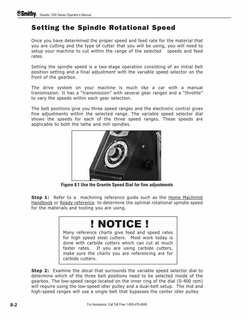
Setting the Spindle Rotational Speed
Once you have determined the proper speed and feed rate for the material thatyou are cutting and the type of cutter that you will be using, you will need tosetup your machine to cut within the range of the selected speeds and feedrates.
Setting the spindle speed is a two-stage operation consisting of an initial beltposition setting and a final adjustment with the variable speed selector on thefront of the gearbox.
The drive system on your machine is much like a car with a manualtransmission. It has a “transmission” with several gear ranges and a “throttle”to vary the speeds within each gear selection.
The belt positions give you three speed ranges and the electronic control givesfine adjustments within the selected range. The variable speed selector dialshows the speeds for each of the three speed ranges. These speeds areapplicable to both the lathe and mill spindles.
Step 1: Refer to a machining reference guide such as the Home MachinistHandbook or Ready reference to determine the optimal rotational spindle speedfor the materials and tooling you are using.
Step 2: Examine the decal that surrounds the variable speed selector dial todetermine which of the three belt positions need to be selected inside of thegearbox. The low-speed range located on the inner ring of the dial (0-400 rpm)will require using the low-speed idler pulley and a dual-belt setup. The mid andhigh-speed ranges will use a single belt that bypasses the center idler pulley.
Figure 8.1 Use the Granite Speed Dial for fine adjustments
! NOTICE !Many reference charts give feed and speed ratesfor high speed steel cutters. Most work today isdone with carbide cutters which can cut at muchfaster rates. If you are using carbide cutters,make sure the charts you are referencing are forcarbide cutters.
Granite 1300 Series Operator’s Manual
8-2 For Assistance: Call Toll Free 1-800-476-4849

Step 3: Set up the belts as necessary to obtain the desired speed range. Thevariable speed selector dial can be used to adjust the speed within the range.
High Range-Speed Set-up
Use the procedure below to set up for high speed (1500 to 3000 RPM)operations.
Step 1: Release the belt tensioned at the motor by rotating the tension leverdown.
Step 2: Position the belt around the largest sheave of the motor and thesmallest sheave on the spindle pulley.
Step 3: Tension the belt by rotating the tension lever on the motor all the wayup.
Mid Range-Speed Set-upUse the procedure below to set up for middle speed (400 to 1500 RPM)operations.
Step 1: Release the belt tensioned at the motor by rotating the tension leverdown.
Step 2: Position the belt around the center sheave of the motor and thelargest sheave on the spindle pulley.
Step 3: Tension the belt by rotating the tension lever on the motor all the wayup.
! NOTICE !The life of the electrical system will be greatly extended andavailable machine torque increased by using the lower pulleysetting and keeping the motor speed up.
Machines purchased after mid-2003 have the speed reducerpulley installed on the machine. A retrofit kit, part number 40-300G, to add this feature to earlier machines is available fromthe Smithy Sales Department at 1-800-476-4849 or atwww.smithy.com.
8: Speeds & Feeds
8-3Or Visit www.smithy.com

Low Range-Speed Set-upFor low-speeds (optional on early machines), you must convert to a doubledrive belt configuration. Use the procedure below to set up for low speed (400RPM or less) operations.
Step 1: Release the belt tensioned at the motor by rotating the tension leverdown.
Step 2: Remove the belt from the motor pulley by following steps 3-6 below.
Step 3: Loosen the cap screw on the shaft of the lathe/mill clutch inside thepulley box and pull the selector lever outward to move the shifter fork arm awayfrom the shifter fork.
Step 4: Slide the single belt off the spindle pulley and the end of the maindrive spindle.
Step 5: Loosen the bolt that holds the gear quadrant and the reduction pulleybracket in place. This will allow the two belts you are about to install to beproperly tensioned.
Step 6: Place the larger of the two belts on the smallest motor pulley sheaveand on the largest pulley sheave of the speed reduction pulley. Place thesmaller belt on the smallest sheave on the speed reduction pulley and thelargest sheave on the main drive spindle pulley.
Motor Motor
High SpeedRange
Mid SpeedRange
Figure 8.2 The high & mid-speed ranges only require the use of one belt
Figure 8.3 Loosen the cap screw from the lathe-mill clutch lever
Lathe/MillClutch Lever
Shifter Fork Arm
Granite 1300 Series Operator’s Manual
8-4 For Assistance: Call Toll Free 1-800-476-4849

Step 7: Tension the belts by rotating the tension lever on the motor all theway up. Tighten the bolt on the gear quadrant to lock the quadrant and thereduction pulley in place.
Step 8: Reassemble the lathe/mill selector arm and tighten the cap screw tosecure the selector shaft in place.
Feed Chart Explained
Before setting the feed rates, it is important to know how to correctly read thefeed rate and threading chart found on the headstock of your Granite 1300series machine.
The chart is comprised of six vertical sections (one header and five datasections) and four horizontal sections (one header and three data sections).
Section 1 is headed by the symbol at the left. The meaning is“Do NOT change selector handle positions while themachine is running”. Please stop the machine while changingfeed directions, gear selections, feed-rate selections, etc.”
Figure 8.5 Low Range Belt Setting
Figure 8.4 Loosen the bolt of the speed reduction pulley bracket when installing belts for the low speed
Low SpeedRange
Motor
8: Speeds & Feeds
8-5Or Visit www.smithy.com

Below the symbol is a representation of the feed gears, A, B, C, and D on thegear quadrant. These gears are located inside the pulley box. Immediately tothe right of the gear symbols are the numbers 1 through 7, which refer to theposition of the powerfeed selection lever (1-7) on the feed transmission.
Below the gear symbols is the location guide for the gear numberswhich are stamped on the face of the gears. This formula refers towhich gear number belongs in which location in order to move the
carriage or table for threading and powerfeeding.
A CB D
X
1”N
in in in in
A
B
C
D
7 14 28 0.125 0.250 0.500 0.039 0.079 0.157 0.35 0.70 1.75 3.50
8 16 32 0.109 0.218 0.437 0.034 0.069 0.138 0.40 0.80 1.00 2.00 4.00
9 18 36 0.097 0.194 0.388 0.031 0.061 0.122 0.45 4.50
10 20 40 0.087 0.175 0.349 0.028 0.055 0.110 0.50 1.00 1.25 2.50 5.00
11 22 44 0.079 0.159 0.317 0.025 0.050 0.100 2.75 5.50
12 24 48 0.073 0.146 0.291 0.023 0.046 0.092 0.60 1.50(0.75) 3.00 6.00
13 26 52 0.067 0.134 0.269 0.021 0.042 0.085 3.25 6.50
II III III II I III II I III II I III II I
X 30 6066 60
X 33 6380 60
X (33)66 6364 60
X
1
2
3
4
5
6
7
A CB D
I
INCH METRIC INCH METRIC
Header Section 1 Section 2 Section 3 Section 4 Section 5
Figure 8.6 Feed Rate Chart
Granite 1300 Series Operator’s Manual
8-6 For Assistance: Call Toll Free 1-800-476-4849

Below the gear formula is a repetition of the “Do not change selectorhandle positions while the machine is running” symbol.
The Header Row contains a number of symbols explained below:
This symbol refers to inch thread pitches (threads per inch).The “N” represents the distance the carriage assemblytravels for each rotation of the spindle based on the positionsof the selector lever (I-III) and selector lever 1-7. Forexample, if the distance traveled in one rotation of thespindle is 1/10 inch per rotation, the machine will travel 1inch in 10 rotations, yielding 10 threads per inch (tpi).
This symbol represents the longitudinal (X-Axis Travel) ininches per spindle revolution.
This symbol represents the lateral Y-Axis Travel) ininches per spindle revolution.
This symbol refers to the the inch thread pitch. Inch pitchesmeasures the distance between each thread peak.
Directly below this set of symbols is a row of Roman Numbers I-III, This rowrepresents the position of the selector lever (I-III) when cutting a threads ordetermining a feed rate.
Section one of the chart list the inch thread pitches that can be cut with theGranite series machines. The last row corresponding with the gear locationguide shows the position of the gears inside the pulley box. When cutting inchthreads the following gears are required:
A=30B=66C=60D=60
This is the default setting from the factory.
Section two of the chart list the feed rates for the X-Axis (longitudinal feed).The same gear set-up is required as for cutting inch threads.
Section three of the chart list the feed rates for the Y-Axis (lateral feed). Thesame gear set-up is required as for cutting inch threads.
1”N
in
in
in
8: Speeds & Feeds
8-7Or Visit www.smithy.com

Section four and five of the chart list the metric thread pitches when using thefollowing gear set-up:
Section 4 Section 5A=33 A=66B=80 B=64C=63 C=63D=60 D=60
Changing gears will be covered in the Threading chapter.
Sample Settings
Here are a couple of examples to illustrate the speed/feed chart.
Example 1Settings to thread 10 threads per inch.
In section 1, locate number 10. Follow the row over to the column next to themeshing gears which is the number 4. Follow the column up to the RomanNumerals which is Roman Numeral I. To cut this thread you will need:
1. Selector lever (1-7) in position 42. Selector lever (I-III) in position I3. 30 tooth gear in position A4. 66 tooth gear in position B5. 60 tooth gear in position C 6. 60 tooth gear in position D. 7. Set the Inch/Metric selector, found in the pulley box, to Inch.
Example 2Setting to move the carriage assembly 0.0069 in per spindlerevolution.
Locate the rate 0.159 in section 2. Follow the row over to the column next tothe diagram of the meshing gears which is 5. Follow the column up to theRoman Numerals which is II. To feed your carriage at this rate you will need to:
1. Selector lever (1-7) in position 52. selector lever (I-III) in position II3. 30 tooth gear in position A4. 66 tooth gear in position B5. 60 tooth gear in position C 6. 60 tooth gear in position D. 7. The Inch/Metric selector found in the gear box would need to be set to Inch.
These example settings will aid you in correctly setting up your machine forpowerfeeding which will be covered in the next section of this manual.
Granite 1300 Series Operator’s Manual
8-8 For Assistance: Call Toll Free 1-800-476-4849

NOTES:
! NOTICE !The feed chart on your machine is in millimetersper spindle revolution. Please see Appendix B forfeed rates based in inches per spindle revolution.
8: Speeds & Feeds
8-9Or Visit www.smithy.com

Overview
The previous section of this manual explained speeds and feed and how theyare determined. This section will give you step by step instructions for usingthe powerfeed on your Granite 1300 series lathe-mill-drill.
General machining practices can be found in the one of the many machiningreference books that Smithy carries such as the Home Machinist Handbook, item10-005.
Powefeeding Defined
Power feeding is using the motor and gear train of the machine to providepower to move the cross-slide table and carriage assembly along the X andY-axes.
The carriage can be moved longitudinally and the cross-slide table laterallyusing the powerfeed capabilities of the machine. Power feeding will give a moreuniform finish on the workpiece and is available for both milling and lathe work.
9 Using Powerfeeds
General Safety Operations
For your own safety and the safety of those around you, followthe rules below and those listed in chapter 2 of this manual.
Never leave or walk away from an operating machine.
Do not change motor rotation direction until the motor andspindle are fully stopped. Changing directions while the motoris running can damage the motor.
CAUTION
CAUTION
DANGER
9-1 For Assistance: Call Toll Free 1-800-476-4849

The powerfeed operates in either the x- or y-axis. It incorporates the quickchange gear box by engaging the Selector Lever (1-7) and Selector Lever (I-III)as well as the carriage gearing by engaging the powerfeed lever into theproper position.
The two-position powerfeed function selector mustbe in either the lathe or mill position according towhich machine function is being used at the time.
CAUTION
Figure 9.1 Always match the Powerfeed Function lever to the appropriate operation
Figure 9.2 Selector Lever (1-7) & Selector Lever (I-III)
! NOTICE !If the mill/lathe clutch is in the mill position, youmust also position the powerfeed function selectorin the mill position to enable the machine to movethe table.
9:Using Powerfeeding
9-2Or Visit www.smithy.com

The powerfeed engagement lever is located on the upper right side of the apronand has a three-position gate with neutral, longitudinal (x axis) and cross feed(y axis). The powerfeed engagement lever can be operated while the machineis running.
Engagement of the x axis is achieved by moving the lever to the left andpushing down and the engagement of the y axis is to the right and lifting up.
Figure 9.3 Powerfeed Engagement Lever Shown with Y-Axis powerfeed engaged
Figure 9.4 Half Nut Disengaged
Don’t allow the table to move beyond the travel limitations.Before running the powerfeed, do a “dry run” by manuallyfeeding the cross-slide table and carriage assembly thedistance that you will be feeding your project. This willprevent any unnecessary crashes that can cause seriousdamage to your machine.
DANGER
Granite 1300 Series Operator’s Manual
9-3 For Assistance: Call Toll Free 1-800-476-4849

The Jog Knob
The chrome knurled knob located on the upper right side of the gearbox can be used tomanually turn the gear shafts and allow the straight cut gears to mesh easier whenmoving the powerfeed selector levers.
Step-By-Step Lathe Powerfeeding
Step 1: Determine the proper speed and feed rate for the material you arecutting and the cutter you will be using from a general reference guide such asthe Machinist Ready Reference.
Step 2: With your workpiece and tooling properly mounted, place the power-feed selection lever in the lathe mode by moving the lever to the lathe chuckicon all the way to the left.
Step 3: Referencing the chart on the front of the machine’s headstock, find thedesired feed rate (or the closest to the listed range for your work materialcutter.) See section 8 for a detailed chart explanation.
Step 4: Position the selector (1-7) into the position listed on the chart for thedesired feed rate.
Figure 9.5 Jog Knob
! NOTICE !When using the X-Axis powerfeed for a given feed rate,make sure the the half nut is DISENGAGED.
If the powerfeed lever will not engage, first check thehalf-nut lever. The powerfeed will not engage if thehalf-nut is engaged (down position). You may also have asituation where the teeth on the respective gears are notmeshing. Rotate the leadscrew handwheel slightly to allowthe teeth to mesh.
! NOTICE !
9:Using Powerfeeding
9-4Or Visit www.smithy.com
Step 5: Position the selector (I-III) into the position listed on the chart for thedesired feed rate.
Step 6: Set the recommeded speed for the work stock material and cutter thatyou are using. (See chapter 8 for setting speeds.)
Step 7: Before running the powerfeed do a “dry run” by manually feeding thecross-slide table and carriage assembly the distance that you will be feedingyour project. Also, rotate the chuck by hand to verify tool clearances. This willprevent any unnecessary crashes.
Step 8: Once your speed has been set start the machine and engage thepowerfeed selector into the desired position. (Pushing the lever up will run thepowerfeed along the Y-Axis. Pushing the lever down will engage the X-Axispowerfeed.)
Step 9: To stop powerfeeding, disengage the powerfeed by moving the leverinto the neutral position which is half way between the Y-Axis and X-Axisengagement.
Step I0: If you wish to reverse the direction of your cut,stop the machine andmove the leadscrew rotation lever into the opposite direction. Restart themachine and engage the powerfeed selector lever.
Step-By-Step Mill Powerfeeding
Step 1: Determine the proper speed and feed rate for the material your cuttingand the cutting material you will be using from a general reference guide suchas the Machinist Ready Reference.
Step 2: With your workpiece and tooling properly mounted, place thepowerfeed selection lever in the mill mode by moving the lever to the millspindle icon all the way to the right. (Reference figure 9.1 above.)
Step 3: Referencing the chart on the front of the machine’s headstock, find thedesired feed rate (or the closest to the listed range for your work material andcutter.)
Step 4: Position the selector (1-7) into the position listed on the chart for thedesired feed rate.
Step 5: Position the selector (I-III) into the position listed on the chart for thedesired feed rate.
! NOTICE !For optimum performance, be certain to set the belts to run in theupper portion of the suggested spindle rotation speed range.
Granite 1300 Series Operator’s Manual
9-5 For Assistance: Call Toll Free 1-800-476-4849
Step 6: Set the recommended speed for the work stock material and cutterthat you are using. (See chapter 8 for setting speeds.)
Step 7: Before running the powerfeed do a “dry run” by manually feeding thecross-slide table and carriage assembly the distance that you will be feedingyour project. This will prevent any unnecessary crashes.
Step 8: Once your speed has been set start the machine and engage thepowerfeed selector into the desired position. (Pushing the lever up will run thepowerfeed along the Y-Axis. Pushing the lever down will engage the X-Axispowerfeed.)
Step 9: To stop powerfeeding, disengage the powerfeed by moving the leverinto the neutral position which is half way between the Y-Axis and X-Axisengagement.
! NOTICE !For optimum performance be certain to set the belts to run in theupper portion of the suggested spindle rotation speed range.
9:Using Powerfeeding
9-6Or Visit www.smithy.com

Overview
This section of your manual covers threading operations on your Granite 1300series lathe-mill-drill. This section will build the information presented inchapters 8 and 9. If you have not read these sections, please do so beforecontinuing.
Leadscrew Safety Clutch Adjustment
Before begining your threading operation, note the leadscrew safety clutch mayneed to be adjusted.
The lead screw safety clutch is functioning in the threading mode. It will slip toprevent damage to the machine apron if the carriage is accidentally run into thehead of the machine.
NOTE: The clutch will not prevent damage if the carriage or cross-slide tablepass the end of their mechanical limits
The clutch assembly is located inside the lathe pulley box. It is a round flat nubin the change gear shaft with the “D” gear. There are six setscrews above thesprings and ball bearings located radially around the clutch in front of the gear.The setscrews screw inward toward the center of the clutch.
10 Threading
General Safety Operations
For your own safety and the safety of those around you, followthe rules below and those listed in chapter 2 of this manual.
Never leave or walk away from an operating machine.
Do not change motor rotation direction until the motor andspindle are fully stopped. Changing directions while the motoris running can damage the motor.
CAUTION
CAUTION
DANGER
10-1 For Assistance: Call Toll Free 1-800-476-4849

If slippage occurs during your threading operation adjust the safety clutch byturning each setscrew one at a time a half turn each time untill the clutch issolid and no slippage occurs. Do not bottom the screws completely of the clucthwill not work.
An approximate initial setting is when the set screws have two threads exposedfrom the surface of the clutch housing.
Basic Threading
Refer to a machining reference guide such as the Machinist Ready Reference forthreading theory and spindle speeds based on the material type and diameterthat you will be machining.
Step 1: Select the thread pitch which you want to cut from the chart locatedon the headstock of your Granite series machine (The is also reprinted on page8-5 of this manual.) Chose the desired pitch from the chart and follow thehorizontal row and vertical columns to set the correct positions for selectorlevers (1-7) and selector lever (I-III).
Step 2: Consult the thread chart on the headstock support column for thethread pitch that you wish to cut. The bottom row of the chart will show youthe gear set-up inside the pulley box that is required to cut the desired threadpitch.
Figure 10.1 Leadscrew Safety Clutch
Figure 10.2 Selector Lever (1-7) & Selector Lever (I-III)
10: Threading
10-2Or Visit www.smithy.com

Step 3: If changing the gear set-up is necessary to achieve the desired threadpitch, follow the procedure under the title “Changing Gears” in the next section.
Changing Gears
Step 1: The A gear is secured with a bolt and washer assembly and thelocation is fixed. To remove the gear remove the bolt and washer.
Step 2:The B and C gears share the same shaft and are secured with a snapring. Remove the snap ring from the shaft to remove the gears.
Step 3: Place the proper gear in the A position for cutting the desired threadpitch. Reinstall the washer and bolt.
Step 4:The shaft for the B/C gears mounts on a slotted plate to adjust for thedifferent diameters of the gears. There are two flats on the end of the shaft toloosen and tighten the assembly to allow for adjustment. Adjust the B/C gearshaft as needed to accommodate the B and C gears needed for cutting yourdesired thread pitch.
Figure 10.3 Make certain that your gears are properly set-up to obtain the desired thread pitch
A
BC
Figure 10.4 Inch/metric Selector located inside the pulley box
Granite 1300 Series Operator’s Manual
10-3 For Assistance: Call Toll Free 1-800-476-4849

Step 5: Loosen the hex head bolt. This allows the assembly to drop down.
Step 6: Position the installed B/C gear unit to mesh with the D gear.
Step 6: Rotate the gear assembly until the B gear meshes with the A gear.Lock the assembly in place by tightening the hex head bolt.
The hex head bolt also tensions the speed reduction pulley support arm. Besure the belts are in the appropriate position before tightening the hex headbolt.
Cutting Inch Threads
Step 1: Select the desired thread pitch that you wish to cut from the chartlocated on the headstock of the Granite 1300 series lathe-mill-drill.
Step 2: Engage selector levers (1-7) and selector lever (I-III). Remember, youcan use the jog knob located on the right side of the gear box to help align thegears if the levers are difficult to engage.
Step 3: Check the gear set-up inside the pulley box to confirm the gearing isset-up correctly to cut your desired thread pitch. If the gears are not correct,change gears using the previous procedure.
NOTE: The default factory setting is for cutting inch, SAE, threads.
Step 4: Confirm that your belts inside the pulley box are properly set-up toreach the recommended spindle speed for cutting your work piece material withyour specific cutter.
Step 5: Set your compound angle toolpost to 29-1/2º and install the E8carbide bit that came with your machine.
Step 6: Inside the pulley box at the left lower side of the gear cluster is theinch/metric lever, which must be pushed away from you for inch threading.
Step 7: Turn your machine on and adjust variable speed to the recommendedspeed.
Step 8: Once you have made all of your tooling and machine settings, you areready to begin the first pass. Set the dials on the compound angle toolpost andcross-slide table to zero. Move the compound angle toolpost into the desiredposition and feed the cutter into your workpiece using the small CATP feedhandle. Watch the threading dial rotate until one of the numbers is just aboutto the reference mark. At this point apply firm constant downward pressure onthe half-nut engagement lever until you feel the lever drop into position and thecarriage begins to move. (More information to follow on the threading dial.)
10: Threading
10-4Or Visit www.smithy.com

Step 9: When you reach the end of the first cut, lift up on the half-nutengagement lever, back the cutter out using the CATP feed and return thecutter to the starting point.
Step 10: Feed the cutter in the desired amount for the next cut, wait for thesame number as before to come up on the dial and engage the half nut.Continue making passes until you have completed the full depth of cut.
Using the Threading Dial to Cut InchThreads
The threading dial is used for cutting inch threads only. Special procedures forcutting metric threads can be found in the section under “ Cutting MetricThreading” on the next page.
The threading dial is a mechanical indicator for engaging the cutter at the exactsame point for each consecutive pass. The numbers on the dial have nospecific reference to pitch, but they provide a reference point so you can startat the earliest available point and use the same number again for eachconsecutive pass.
No t e : When the carriage is moving and the half nut is engaged, you will noticethat the dial no longer rotates. This is normal.
Figure 10.5 Half Nut Engaged
Figure 10.6 Note the number on the threading dial as your halfnut engages
Granite 1300 Series Operator’s Manual
10-5 For Assistance: Call Toll Free 1-800-476-4849

Cutting Metric Threads
Step 1: Select the desired thread pitch that you wish to cut from the chartlocated on the headstock of the Granite 1300 series lathe-mill-drill.
Step 2: Engage selector levers (1-7) and selector lever (I-III). Remember, you can use the jog knob located on the rightside of the gear box to help align the gears if the levers are difficult to engage.
Step 3: Check the gear set-up inside the pulley box to confirm the gearing isset-up correctly to cut your desired thread pitch. If the gears are not correct,change gears using the previous procedure.
Step 4: Confirm that your belt set-up inside the pulley box is properly set-upto reach the recommended spindle speed for cutting your work piece materialwith your specific cutting tool material.
Step 5: Set your compound angle toolpost to 29-1/2º and install the E8carbide bit that came with your machine.
Step 6: Inside the pulley box at the left lower side of the gear cluster is theinch/metric lever, which must be pulled toward you for metric threading.
Step 7: Turn your machine on and adjust the variable speed to therecommended rpm.
Step 8: Once you have made all of your tooling and machine settings, you areready to begin the first pass. Apply firm constant downward pressure on thehalf-nut engagement lever until you feel the lever drop into position and thecarriage begins to move. .Step 9: Do not disengage the half nut at the end of the pass, stop yourmachine and reverse the feed direction. Rotate the handle on the compoundangle toolpost counter clockwise to back out your cutter.
Step 10: Restart your machine and bring the cutter back to is originalposition. Stop your machine, reverse the direction again.
Step 11: Feed the cutter in the desired amount for the next cut using the CATPand restart your machine. Continue this process until you have reached thedesired depth of cut.
10: Threading
10-6Or Visit www.smithy.com

Overview
To keep your Smithy Granite machine running at optimum performance, followthis basic maintenance schedule:
Before Each Use
1. Make sure your work area is clean and free of all obstructions.
2. Clear machine cross-slide table, bed ways and tool post of all chips builtup from your previous job.
3. Oil all oil buttons.
4. Clean tailstock barrel taper and mill spindle taper with a clean shop towel.
5. Check the oil site gauge under the lathe chuck and add oil if the level is below thehalf-way point.
6. Check all tooling and holding devices for tightness before you turn on the machine.
7. Check the condition and tension of the drive belts.
After Each Use
1. Clean chip build up from machine.
2. Brush chips off the longitudinal feed screw.
3. Remove any excess cutting fluid that may have accumulated on the machine.
4. Apply protective oil coating to all bare metal surfaces that may rust or corrode.
11 Machine MaintenanceSchedule
Do not clear chips by hand. Metal chips are very sharp and caneasily cut your hand. Use a brush or shop vaccum to clear chips.
CAUTION
11-1 For Assistance: Call Toll Free 1-800-476-4849

10 Hours (Daily)
1. Clean chip build up from machine.
2. Brush chips off the longitudinal feed screw.
3. Check the oil site gauge under the lathe chuck and add oil if the level is below thehalf-way point.
4. Oil all oil buttons
25 Hours (Monthly)1. Check the oil site gauge under the lathe chuck and add oil if the level is below the
half-way point.
2. Oil all oil buttons
3. Apply a light coating of oil to the outside of the mill spindle and the top of the millspindle splines.
4. Lubricate the change gears in the lathe pulley box with an aerosol chain lubricant.
5. Lubricate the inside of the quick change gearbox with an aerosol chain lubricateby spraying through the openings in the front of the gearbox.
6. Remove and clean the lathe chuck and the spindle nose. Lubricate the chuck andthe cam locks with oil.
7. Check all gib adjustments.
8. Check and adjust backlash as necessary.
9. Check the condition of all drive belts and replace if necessary.
100 Hours (Yearly)
1. Change oil in the headstock.
2. Remove the X and Y-Axis gibs and clean with solvent. Coat gibs with wayoil and reinstall.
11: Maintenance Schedule
11-2Or Visit www.smithy.com

Powerfeed and Thread Cutting
1. Powerfeed does not move carriage
Cause Solution
• Carriage locked • Unlock carriage• Speed selector not engaged • Select speed I or II or III, engage
drive selector• Sheared pin • Replace pin• Gears not meshing or teeth missing • Check gears and adjust• Inch/metric lever in neutral • Engage fully
2. Cut is not smooth
Cause Solution
• Tool dull • Sharpen or replace tool• Tool not on center • Center tool (shim, if needed)• Tools not mounted tightly in post • Remount tools• Cross-slide gibs to bed and base loose • Adjust gibs • Gibs in toolpost loose • Adjust gibs in toolpost• Tool turret not tight • Tighten toolpost• Feed rate too fast • Choose correct setting• Gear loose • Tighten gears and posts
3. Thread is not smooth
Cause Solution
• Tool dull • Sharpen tool• Tool not centered • Center tool• Tools not mounted tight in post • Remount tool• Cross-slide gibs to bed and base loose • Adjust gibs• Gibs in compound loose • Adjust gibs• Tool turret not tight • Tighten toolpost• Gears loose • Tighten gears and posts
4. Tools is not cutting “on thread”
Cause Solution
• Powerfeed slipping • Engage halfnut fully• Clutch slipping • Tighten screws (6)
12 Troubleshooting
12-1 For Assistance: Call Toll Free 1-800-476-4849

Carriage/Milling Table
1. Table won't move
Cause Solution
• Table locks engaged • Loosen locks• Gibs too tight • Loosen gibs
2. Horizontal and vertical movement in cross-slide table
Cause Solution
• Carriage gib improperly adjusted • Adjust carriage gib• Table gib improperly adjusted • Adjust table gib
3. Carriage moves smoothly in only one direction
Cause Solution
• Debris on way or gib • Remove debris• Burr on gib • Remove burr with fine file• Gib improperly tensioned • Loosen gib and re-tension• One or more wipers mounted too low • Reposition wiper(s)
4. Cross-slide handwheel turns during cutting operations
Cause Solution
• Cross-slide brass nut worn • Tighten or replace brass nut• Carriage lock not tight • Tighten carrriage locks• Gibs too loose • Readjust gibs
5. Too much backlash in the cross-slide
Cause Solution
• Loose screw • Tighten screw, review how to eliminate backlash
• Loose brass nut • Put a shim between the stud on the nut and the side of the hole
• Worn brass nut • Replace brass nut or adjust screw at end of nut
• Excessive space between bearing • Add shim washer and dial
12: Troubleshooting
12-2Or Visit www.smithy.com

Lathe Turning
Cause Solution
• Tool dull • Sharpen or replace tool• Tool not ground properly • Regrind tool• Tool at wrong angle • Correct tool position • Tools not held tightly • Tighten toolholder• Wrong cutter for material • Use correct cutter• Cutting speed incorrect • Increase or reduce speed
2. Work has unwanted taper
Cause Solution
• Work improperly aligned • Realign centers on work• Debris in spindle, setup, or tools • Clean and reset setup, work, or
tool• Offset tailstock incorrectly positioned • Correct position of tailstock• Spindle bearings loose • Tighten taper bearings to return to
alignment, replace spindle bearings
3. Machine vibrates
Cause Solution
• Work mounted wrong • Remount work• Speed too high • Reduce Speed• Too much pressure at tailstock • Reduce pressure and increase
lubrication
4. Work stops turning but machine continues to run
Cause Solution
• Work not mounted securely • Remount work• Tools forced into work/ excessive cut • Reduce force on tools• Belts slipping • Tension belts, use belt dressing, or
replace belts
5. Diameter of work is not consistent
Cause Solution
• Too much flex in workpiece • Use a follow rest, use tailstock center
• Too much flex compound rest, • Tighten gibs, clean ways cross slide, or carriage
Granite 1300 Series Operator’s Manual
12-3 For Assistance: Call Toll Free 1-800-476-4849

6. Too much backlash in the compound
Cause Solution
• Loose spanner nuts • Tighten spanner nuts• Worn Nut • Replace nut
7. Machine slings oil from behind the chuck or in belt box
Cause Solution
• Oil reservior overfilled • Check oil lever• Worn oil seal • Replace felt in seal
Milling
1. Tool chatter
Cause Solution
• Gibs too loose on cross slide, • Readjust gibs compound, or carriage
• Unused feeds not locked • Lock all axes but the one moving • Millhead not locked • Lock millhead• Quill too loose • Tighten quill lock• Tool not on center • Center tool• Improper tool shape, tool dull • Reshape, sharpen, or replace tool• Feed too light or slow • Adjust feed rate
2. Depth of cut is not consistent
Cause Solution
• Quill moving • Lock quill• Setup wrong • Make sure setup is parallel to
table
Drilling
1. Hole is off center or bit wanders
Cause Solution
• Bit dull • Use sharp bits• Bit not mounted correctly in chuck • Remount tool• Bit bent • Replace bit• Chuck loose in spindle • Remount chuck on arbor• Drawbar not secured • Tighten drawbar• Debris on spindle • Clean debris and arbor and
remount tool• Bearing loose or worn • Tighten or replace bearings
12: Troubleshooting
12-4Or Visit www.smithy.com

• Cutting too fast • Reduce speeed• Incorrect bit • Use correct bits• No pilot hole • Drill small pilot hole
2. Entrance hole is out of round
Cause Solution
• Bit dull • Use sharp bit• Incorrect drill bit • Use correct drill bit
3. Bit turns erratically or stops
Cause Solution
• Bit fed into work too fast • Reduce feed rate• Belts slipping • Reduce feed rate, re-tension belts
4. Chuck is difficult to tighten or loosen
Cause Solution
• Chuck sticking • Apply lubricant• Debris in chuck • Clean chuck
5. Chuck wobbles
Cause Solution
• Chuck loose on arbor • Clean arbor and remount• Drawbar not tight • Clean spindle and replace drawbar
Drive System
1. Turn on the machine and nothing happens
Cause Solution
• Breaker Blown • Re-set circuit breaker• Machine unplugged • Plug in the machine• Loose electrical connections • Tighten wiring connections• Electrical components bad • Replace defective parts
2. Motor and pulleys turn, but not lathe or mill
Cause Solution
• Mill or lathe not selected • Select proper function
Granite 1300 Series Operator’s Manual
12-5 For Assistance: Call Toll Free 1-800-476-4849

Motor
How to check a Motor
Get a car battery and attach the two wires coming from the motor to the terminals of thebattery. If the motor runs, the motor is okay, if not it needs to be replaced.
Uncscrew brush caps and inspect the brush carbon, spring and wire. If damaged or wornout replace it.
Chuck and Accessories
If the chuck does not seat properly.
Adjusting the chuck mounting studs
The D1-4 mounting system used on all Granite machines consists of three adjustablestuds mounted on the chuck and three rotating cam locks on the spindle flange. This isa very fast and accurate method of chuck mounting; however, there are someadjustments to be made to insure optimum fit and accuracy.
Removing the chuck
1. The first step in removing the chuck is to place a piece of wood on top of the machinebed underneath the chuck. This will protect the bed if the chuck accidentally slips out ofyour hand and falls onto the machine.
2. There is an alignment mark on each cam and on the spindle flange adjacent to eachcam. Using the chuck key, turn the cam counter clockwise until the two marks align witheach other as shown below.
3. Position all three cams in the unlocked position, put your right hand under the chuckfor support and tap the chuck with a block of wood to break it loose from the spindle.
SpindleFlange
Unlocked
D1-4 CamlockTooling
Cam in Unlocked Position
SpindleFlangeLocked
D1-4 CamlockTooling
Cam in Locked Position
Figure 12.1 D1-4 Lathe Chuck in Locked & Unlocked Position
12: Troubleshooting
12-6Or Visit www.smithy.com

4. Inspect the mating surfaces on the end of the spindle and the back of the chuck forburrs or foreign matter. Clean and deburr these areas as necessary.
Installing and Adjusting the chuck
1. Make sure that the cams are aligned in the unlocked position and slide the chuckonto the spindle.
2. Turn each cam clockwise to lock the chuck in place.
3. Each cam should turn between 140o to 180o of a turn to lock correctly. See the dia-gram below.
4. If the cam turns less than one fourth of a turn, it will be necessary to remove thechuck and adjust the corresponding chuck stud.
5. Before removing the chuck, mark each location on the chuck that will needadjusting.
6. Remove the chuck and place it face down on a work surface.
7. There is a locking screw along side each chuck stud. Remove the locking screws forthe studs that need adjusting.
8. Unscrew the studs one turn and install the locking screws.
Prefered locking area
StudLock Screw
Figure 12.2 Locking area positon
Figure 12.3 Back of the chuck
Granite 1300 Series Operator’s Manual
12-7 For Assistance: Call Toll Free 1-800-476-4849

9. Install the chuck and check the cam rotation. Repeat as necessary.
Since there are three studs and cam mounts on the chuck, there are three possibleposition that the chuck may be mounted. You will find that one of these positions will beslightly more accurate than the others. Try the chuck in all three possible positions. Oncethe most accurate position is determined, mark the chuck and spindle flange so that thechuck can be installed in the same position each time that it is mounted onto themachine. This is best done by putting a punch mark on the chuck and a correspondingmark on the spindle flange.
This next step is only for the 3-jaw self centering chuck.
Mark each of the three jaws, and the slot it is in. Remove the jaws, and keeping themin the same order, reinsert them into the next slot over making sure the scroll plateengages the first thread on the first jaw. Try the jaws in all three positions; one shouldbe more accurate than the other two.
Leadscrew
Having trouble on the leadscrew backlash particularly on engaging the halfnut?
Leadscrew Backlash Adjustment
Excessive backlash in the longitudinal feed can come from two places:
1. The fit of the longitudinal feed screw to the right hand mounting trestle.
2. The fit of the half nut to the feed screw.
Screw to mount backlash
Engage the half nut lever. Slowly turn the longitudinal feed screw clockwise as viewedfrom the right end of the machine and watch the gap between the dial and the feed screwmounting trestle. Reverse the direction you are turning the feed screw and see if the gapincreases slightly. If so then there is some play in the mounting. To reduce the play,accomplish the following.
1. Remove the bolt/ washer from the right end of the longitudinal feed screw.
2. Unscrew the handle from the end of the feed screw.
3. Using a punch and a small hammer, tighten the spanner nut about one eigth of a turnand recheck the play in the screw.
4. If the play is acceptable, replace the handle and retaining bolt. If more adjustment isneeded, repeat the step above.
12: Troubleshooting
12-8Or Visit www.smithy.com

Half nut to screw backlash
Worn threads on the half nut can cause excessive backlash in the longitudinal direction.Half nuts are made of brass and do wear out over a period of time. The only fix for aworn half nut is to replace the worn nut with a new one.
Crossfeed Backlash Adjustment
Excessive backlash in the crossfeed can be coming from three different places:
1. The fit of the crossfeed screw to the front screw mount.
2. The fit of the crossfeed screw into the brass crossfeed nut.
3. The fit of the brass crossfeed nut into the carriage casting.
There are adjustments for each of the above areas. Before making any adjustments tothe crossfeed screw system, it is recommended that all the gibbs on the table andcarriage system be checked and adjusted as per the owners’ manual.
Crossfeed Screw To Front Mount
Slowly turn the crossfeed handle clockwise and watch the gap between the dial and thefront screw support mount. Change directions and note if the gap increases slightly. If sothis is a sign that there is some play in the mounting. To reduce this play, follow theprocedure below.
1. Loosen the two nuts that hold the crossfeed handle on the end of the screw.
2. Tighten the inner nut slowly while checking the ease of movement of the crossfeed
Lead Screw & Dial Mounting Trestle
Spanner Nut
Handwheel
Retaining Bolt &Washer
Figure 12.4 Parts of the Handwheel
Granite 1300 Series Operator’s Manual
12-9 For Assistance: Call Toll Free 1-800-476-4849

handle. When the screw starts to get hard to turn, loosen the nut slightly so the screwturns free.
3. Hold the inner nut in place and tighten the outer nut against it to lock the nuts inposition.
4. Recheck the backlash.
Crossfeed Screw to Brass Nut & Nut to Carriage (Locking Bolt)
If there is still an excess of backlash after the above adjustments are made, the play willbe either between the crossfeed screw and the brass nut or between the brass nut andthe carriage. The following procedure covers both adjustments at the same time:
1. Remove the crossfeed screw rear support.
2. Loosen the Allen head bolt that locks the brass nut into the carriage.
3. Crank the crossfeed table toward the operator side of the machine. Watch under thetable from the backside and stop before the crossfeed screw comes out of the brass nut.
Figure 12.5 Crossfeed Screw Parts
Figure 12.6 Crossfeed Table Cross Section
Handle
Inner & OuterNuts
Dial
Support
Note: Watch for gap in this area
CrossfeedTable
12: Troubleshooting
12-10Or Visit www.smithy.com
Cross-slide table
Cross-slide screw
2 Piece Brass Nut
Adjusting Screws
SaddleLocking Bolt

4. Slowly tighten the four adjusting screws on the brass nut, one at a time, until a slightdrag is felt while turning the crossfeed handle.
5. Install the rear crossfeed support and tighten the locking bolt for the brass nut.
6. Recheck the backlash on the crossfeed.
If you find that the four adjusting screws are not staying in place, you can use a smallamount of a thread-locking compound to keep the screws tight.
Granite Series Leadscrew Handwheel Fabrication& Installation (Earlier Machines) Purchase part # G91027 or use the instructions below.
Installation of a handwheel to the right end of the leadscrew will allow a more preciselateral feeding of the carriage travel than is now possible using the carriage feed hand-wheel. The following is a simple handwheel plan that can be made using the Granitemachine. The wheel portion can be made from a piece of mild steel, aluminum, or castiron. The handle portion should be made of mild steel.
Hole is drilled & tapped to matchthe thread of the handle that wasselected. The handle may befabricated from scratch orpurchased already made.
Center hole drilled 27/64and threaded M12 x 1.25
Handwheel dimension - 85mmDiameter - 9mm
9mm long & threaded to match thesmall hole in the handwheel
Diameter & length of the handleyour preference
Screw the handwheel on the end ofthe leadscrew. Install a bolt &fender washer into the 5/16 x 24hole that is in the end of theleadscrew to hold the handwheelin place. Screw the handle into thehandwheel & tighten into place.
Figure 12.7 Crossfeed Table Rear View Cross Section
Figure 12.8 Handwheel Fabrication & Installation
Granite 1300 Series Operator’s Manual
12-11 For Assistance: Call Toll Free 1-800-476-4849
SaddleBrass Nut
Adjusting Screws
Table view from rear ofmachine.

Note: If you have an older Granite model, the end of the lead screw may not be drilledand tapped. This is a very simple process. You will need a 5/16 x 24 tap, a 17/64 or a “I”drill bit, and an electric hand drill. Set up your machine on the slow speed pulley, full RPM,with leadscrew turning counter clockwise as viewed from the right end and the gearboxset on 1 and “I”. By having the leadscrew turning as well as the drill, the drill bit willcenter itself and go straight down the center of the lead screw. Drill the hole about 5/8inch deep. Tap the hole with the 5/16 tap. Do not forget to use oil when drilling andtapping.
NOTES:
12: Troubleshooting
12-12Or Visit www.smithy.com

Granite 1324 Series Machine
General SpecificationsGeneral Dimension: 39” height X 46” length X 22-1/2” widthMachine Weight: Shipping 770 lbs, Machine 661 lbsCrate Size: 49-1/2” X 22-3/4” X 44”Footprint (static): 48” X 36”Footprint (operating): 72-1/2” X 45-1/4”T-Slot Size: 7/16”Spindle Accuracy TIR: 0.00078”Powerfeed (X-Axis): YesPowerfeed (Y-Axis): YesPowerfeed (Z-Axis): NoTable Size: 6-3/4” X 17-3/4”Threading Dial: Yes
Lathe SpecificationsDistance Between Centers: 24”Dial Calibration on Crossfeed: 0.001”Dial Calibration on Toolpost: 0.001”Dial Calibration on Leadscrew: 0.001”Dial Calibration on Tailstock: 0.001”Dial Calibration on Longfeed Rack: 0.01”Headstock Taper: MT4Lathe Chuck- Max. diameter workpiece: 6”Lathe Chuck- Min. diameter workpiece: 1/8”Lathe Chuck Bore: 1.6”Lathe Chuck Diameter: 6”Lathe Chuck Mount: D1-4 CamlockLathe Chuck Type: 3 Jaw Self CenteringSpindle Bore: 1.125”Spindle Speeds: Variable (Range 0-2800 RPM)X-Axis Travel (w/ tailstock installed): 20”Y-Axis Travel: 7-5/8”Feed Rate (X-Axis): 0.003”- 0.020”Feed Rate (Y-Axis): 0.001”- 0.006”Tailstock Offset: 19/32”Tailstock Barrel Travel: 3”Tailstock Taper: MT3Swing Over Bed: 13”Swing Over Work Table: 7-1/2”Threads: SAE 7-52 TPIToolbit Size: 1/2”Toolpost Travel: 3-3/16”
13 Machine Specifications
13-1 For Assistance: Call Toll Free 1-800-476-4849

Mill SpecificationsColumn Diameter: 3-3/16”Dial Calibration Drill-Coarse Feed: 0.05”Dial Calibration Mill-Fine Feed: 0.001” Drawbars Size (included): 7/16”Drill Chuck Size (included): 5/8”Drill Chuck Arbor Size (included): R-8/JT3Head Rotation: 360 DegreesQuill Diameter: 2-3/4”Quill Travel: 4-7/8”Spindle Taper: R-8Spindle to Table Distance (min-max): 4” to 13-3/8”Tool Size Limits: 1”X-Axis Travel: 9-1/2”Y-Axis Travel: 7-5/8”Head Travel (Z-Axis): 4-3/8”Feed Rate (Y-Axis): 0.001”- 0.006”Feed Rate (X-Axis): 0.003”- 0.020”Spindle Speeds: Variable (Range 0-2800 RPM)Spindle Center to Front of Chuck:
GN Classic: 4-5/8”GN-MAX & GN-IMX: 8-1/2”
Spindle Center to Lathe Spindle Flange: GN Classic: 7-1/4”GN-MAX & GN-IMX: 11-1/4”
Spindle Center to Support Column: GN Classic: 9-1/2”GN-MAX & GN-IMAX: 13-3/8”
Electrical SpecificationsAmperage:
GN Classic & GN-MAX: 15 ampsGN-IMAX: 8-10 amps
Horsepower: GN Classic: 1.5 HPGN-MAX & GN-IMX: 2.0 HP
Motor Type: GN Classic: D/C Variable Speed
(Permanent Magnet)GN-MAX & GN-IMX: D/C Variable Speed
(Brushless Servo)Voltage:
GN Classic & GN-MAX: 110 Volts A/CGN-IMX: 220 Volts A/C
Phase: Single
Recommended Oil for LubricantFor Gear Box: SAE30 weight non-detergent
oil or 30 weight compressor oilFor External : Regular Oil For Cleaning: Noncorrosive Kerosene or
White Mineral Spirits or even WD-40
13: Machine Specifications
13-2Or Visit www.smithy.com

Granite 1340 Series Machine
General SpecificationsGeneral Dimention: 39” height X 62” length X 22-1/2” widthMachine Weight: Shipping 910 lbs, Machine 728 lbsCrate Size: 64-1/2” X 22-3/4” X 44”Footprint (static): 64” X 36”Footprint (operating): 88-1/2” X 45-1/4”T-Slot Size: 7/16”Spindle Accuracy TIR: 0.00078”Powerfeed (X-Axis): YesPowerfeed (Y-Axis): YesPowerfeed (Z-Axis): NoTable Size: 6-3/4” X 17-3/4”Threading Dial: Yes
Lathe SpecificationsDistance Between Centers: 40”Dial Calibration on Crossfeed: 0.001”Dial Calibration on Toolpost: 0.001”Dial Calibration on Leadscrew: 0.001”Dial Calibration on Tailstock: 0.001”Dial Calibration on Longfeed Rack: 0.01”Headstock Taper: MT4Lathe Chuck- Max. diameter workpiece: 6”Lathe Chuck- Min. diameter workpiece: 1/8”Lathe Chuck Bore: 1.6”Lathe Chuck Diameter: 6”Lathe Chuck Mount: D1-4 CamlockLathe Chuck Type: 3 Jaw Self CenteringSpindle Bore: 1.125”Spindle Speeds: Variable (Range 0-2800 RPM)X-Axis Travel (w/ tailstock installed): 20”Y-Axis Travel: 7-5/8”Feed Rate (X-Axis): 0.003”- 0.020”Feed Rate (Y-Axis): 0.001”- 0.006”Tailstock Offset: 19/32”Tailstock Barrel Travel: 3”Tailstock Taper: MT3Swing Over Bed: 13”Swing Over Work Table: 7-1/2”Threads: SAE 7-52 TPIToolbit Size: 1/2”Toolpost Travel: 3-3/16”
Mill SpecificationsColumn Diameter: 3-3/16”Dial Calibration Drill-Coarse Feed: 0.05”Dial Calibration Mill-Fine Feed: 0.001” Drawbars Size (included): 7/16”
Granite 1300 Series Operator’s Manual
13-3 For Assistance: Call Toll Free 1-800-476-4849

Drill Chuck Size (included): GN Classic: 1/2”GN-MAX & GN-IMX: 5/8”
Drill Chuck Arbor Size (included): R-8/JT3Head Rotation: 360 DegreesQuill Diameter: 2-3/4”Quill Travel: 4-7/8”Spindle Taper: R-8Spindle to Table Distance (min-max):
GN Classic: 4” to 13-1/3” GN-MAX & GN-IMX: 4” to 13-3/8”
Tool Size Limits: 1”X-Axis Travel: 9-1/2”Y-Axis Travel: 7-5/8”Head Travel (Z-Axis): 4-3/8”Feed Rate (Y-Axis): 0.001”- 0.006”Feed Rate (X-Axis): 0.003”- 0.020”Spindle Speeds: Variable (Range 0-2800 RPM)Spindle Center to Front of Chuck:
GN Classic: 4-5/8”GN-MAX & GN-IMX: 8-1/2”
Spindle Center to Lathe Spindle Flange: GN Classic: 7-1/4”GN-MAX & GN-IMX: 11-1/4”
Spindle Center to Support Column: GN Classic: 9-1/2”GN-MAX & GN-IMX: 13-3/8”
Electrical SpecificationsAmperage:
GN Classic & GN-MAX: 15 ampsGN-IMX: 8-10 amps
Horsepower: GN Classic: 1.5 HPGN-MAX & GN-IMX: 2.0 HP
Motor Type: GN Classic: D/C Variable Speed
(Permanent Magnet)GN-MAX & GN-IMX: D/C Variable Speed
(Brushless Servo)Voltage:
GN Classic & GN-MAX: 110 Volts A/CGN-IMAX: 220 Volts A/C
Phase: Single
4: Machine Overview
13-4Or Visit www.smithy.com

How to Determine Speeds and Feeds for LatheTurning (machine, materials, and tools)
The lathe rotates a workpiece against a cutting edge. With its versatility and numerousattachments, accessories, and cutting tools, it can do almost any machining operation.
The modern lathe offers the following:
• The strength to cut hard, tough materials• The means to apply power• The means to hold the cutting point tight• The means to regulate operating speed• The means to feed the tool into or across, or into and across, the work, either
manually or by engine power, under precise control• The means to maintain a predetermined ratio between the rates of rotating
works and the travel of the cutting point or points
Turning Speed
When metal cuts metal at too high a speed, the tool burns up. You can machine softmetals like aluminum at fast speeds without danger or trouble, but you must cut hardsteels and other metals slowly.
You must also consider the diameter of the workpiece. A point on a 3” diameter shaft willpass the cutting tool three times as fast as a point an a 1”-diameter shaft rotating at thesame speed. This is because the point travels a tripled circumference. For work in anygiven material, the larger the diameter, the slower the speed in spindle revolutionsneeded to get the desired feet-per-minute (fpm) cutting speed.
Lathes cut threads in various numbers per inch of materials threaded, according to theoperator's needs. The Smithy Granite Series machine cuts threads to metric or inchstandards.
In thread cutting, the carriage carries the thread-cutting tool and moves by the rotatingleadscrew. The basic principle is that the revolving leadscrew pulls the carriage in thedesired direction at the desired speed. The carriage transports the toolrest and thethreading tool, which cuts the screw thread into the metal being machined.
The faster the leadscrew revolves in relation to the spindle, the coarser the thread. Thisis because the threading tool moves farther across the revolving metal with eachworkpiece revolution.
Appendix AMachining Reference Guide
A-1Or Visit www.smithy.com

The lathe spindle holding the workpiece revolves at a selected speed (revolution perminute, or rpm) according to the type and size of the workpiece. The leadscrew, whichruns the length of the lathe bed, also revolves at the desired rpm. There is a definite andchangeable ration between spindle and leadscrew speeds.
Cutting Speeds for Various Diameters
FPM 50 60 70 80 90 100 110 120 130 140 150 200 300
DIAM
1/16” 3056 3667 4278 4889 5500 6111 6722 7334 7945 8556 9167 12229 18344
1/8” 1528 1833 2139 2445 2751 3056 3361 3667 3973 4278 4584 6115 9172
3/16” 1019 1222 1426 1630 1833 2037 2241 2445 2648 2852 3056 4076 6115
1/4” 764 917 1070 1222 1375 1538 1681 1833 1986 2139 2292 3057 4586
5/16” 611 733 856 978 1100 1222 1345 1467 1589 1711 1833 2446 3669
3/8” 509 611 713 815 917 1019 1120 1222 1324 1426 1528 2038 3057
7/16” 437 524 611 698 786 873 960 1048 1135 1222 1310 1747 2621
1/2” 382 458 535 611 688 764 840 917 993 1070 1146 1529 2293
5/8” 306 367 428 489 550 611 672 733 794 856 917 1223 1834
3/4” 255 306 357 407 458 509 560 611 662 713 764 1019 1529
7/8” 218 262 306 349 393 426 480 524 568 611 655 874 1310
1” 191 229 267 306 366 372 420 458 497 535 573 764 1146
1-1/8” 170 204 238 272 306 340 373 407 441 475 509 679 1019
1-1/4” 153 183 216 244 275 306 336 367 397 428 458 612 918
1-3/8” 139 167 194 222 250 278 306 333 361 389 417 556 834
1-1/2” 127 153 178 204 229 255 280 306 331 357 382 510 765
1-5/8” 117 141 165 188 212 235 259 282 306 329 353 470 705
1-7/8” 102 122 143 163 183 204 224 244 265 285 306 408 612
2” 95 115 134 153 172 191 210 229 248 267 287 382 573
2-1/4” 85 102 119 136 153 170 187 204 221 238 255 340 510
2-1/2” 76 91 107 122 137 153 168 183 199 214 229 306 459
2-3/4” 69 82 97 111 125 139 153 167 181 194 208 278 417
3” 64 76 89 102 115 127 140 153 166 178 191 254 371
RPM
Granite 1300 Series Operator’s Manual
A-2 For Assistance: Call Toll Free 1-800-476-4849

Cutting Speed and Feeds for High Speed Steel Tools
The energy expended at the lathe's cutting point converts largely into heat, and becausethe energy expended is great, the heat is intense. Before today's HSS, carbide, andceramic tool, this heat created a serious machining problem. Machining could be doneonly under a steady flow of coolant, which kept the tool from heating to its annealingpoint, softening, and breaking down.
With HSS, you can cut dry on cast iron or non-ferrous metals unless a small lathe is running at extremely high speed on continuous, heavy-duty production work. Becausesteel expands when heated, it is a good idea, especially when working on long shafts, tocheck the tightness of the lathe centers frequently and make sure workpiece expansiondoes not cause the centers to bind.
Cutting Speeds and Feeds for High Speed Steel Tools
! NOTICE !The data table provides exact speeds (RPM). Itdoes not take machine speed limitations intoaccount. Determine the desired rate of speed andfind the closest speed available on your machine.
Low-CarbonSteel
High-CarbonSteel
Annealed
Alloy SteelNormalized
AluminumAlloys Cast Iron Bronze
Speed (sfm)RoughingFinishing
90120
5065
4560
200300
7080
100130
Feed (ipr)RoughingFinishing
0.010-0.2020.003-0.005
1.101-0.0200.003-0.005
0.010-0.0200.003-0.005
0.015-0.0300.005-0.010
0.010-0.0200.003-0.010
0.010-0.0200.003-0.10
Appendix A: Machining Reference Guide
A-3Or Visit www.smithy.com

In everyday lathe operations like thread cutting and knurling, always use a cutting oil orother lubricant. On such work, especially if the cut is light and lathe speed low, dippinga brush in oil occationally and holding it against the workpiece will provide sufficientlubrication. For continuous, high-speed, heavy-duty production work, however, especiallyon tough alloy steels, using a cutting oil or coolant will increase cutting efficiency. It'sessential if you're using a non-HSS cutting tool. When you use coolant, direct it againstthe cutting point and cutter. Consider installing a coolant system if you don't have one.
To set up safe rpm rates, you should follow the list for cutting speeds and feeds for HSScutters. The formula is as follows:
rpm = CS x 4 / D”
where:
CS - cutting speed in surface feet per minute (sfm)D” - diameter of the workpiece in inches.
To use this formula, find the cutting speed you need on the chart and plug that numberinto the CS portion of the formula. After calculating the rpm, use the nearest or next-lower speed on the lathe and set the speed.
If you were to make a finish cut on a piece of aluminum 1” in diameter, for example, youwould see the desired sfm is 300. Then
rpm = 300 sfm x 4 / 1
rpm = 1200 / 1
rpm = 1200 or next lower speed.
For high-carbon steel, also 1” in diameter,
rpm = 50 sfm x 40 / 1
rpm = 200 / 1
rpm = 200 or next slower speed.
The four-turret toolpost lets you mount up to four different tools at the same time. Youcan install all standard-shaped turning and facing tools with 1/2” or smaller shanks. Thecenterline is approximately 5/8” above the bottom of the turret. Smithy also offers quick-change tool sets that greatly speed up lathe operations. Contact a Smithy technician fordetails.
Granite 1300 Series Operator’s Manual
A-4 For Assistance: Call Toll Free 1-800-476-4849

How to Determine Speeds and Feeds for Milling(machine, materials, and tools)
Speeds
Milling cutting rates vary according to the machinability of the material being cut; whethercutting fluid is used and, if so, what kind; the type, size, and material of the cutter andthe coarseness of its teeth; and the amount of metal being removed. Cutting speed formilling is the distance the cutting edge of a tooth travels in one minute. If cutting speedis too high, the cutter overheats and becomes dull. If it's too low, production is inefficientand rough.
There is no exact right cutting speed for milling a particular material. Machinist usuallystart with an average speed, then increase or decrease it as needed. For light cuts, usethe upper end. Use the lower end for heavy cuts and when you don't use cutting fluid.
Determining rpm. To set the spindle speed, you have to know the cutter rpm (revolutionsper minute). For inch measurements, use this formula:
rpm = 12 x CS (fpm) / D” x !
where: CS - cutting speedfpm - feet per minute D” - diameter of the cutter in inches! - 3.14 You can use an rpm chart for selected diameters of cutting tools at
different cutting speeds.
For metric measurement, use this formula:
rpm = CS (mpm) x 1000 / D (mm) x !
where:CS - cutting speedmpm - meters per minuteD (mm) - diameter of the cutter in millimeters! - 3.14. You can use an rpm chart for selected diameters of cutting tools at
different cutting speeds.
Change Speeds by selecting the belt location and turning the speed dial
Feeds
Set the direction of feed before you begin milling. Up milling, or conventional milling, iswhen the direction of feed is opposite to the direction of cutter rotation. Down milling, orclimb milling, is when the direction of feed is the same as the direction of cutter rotation.
Appendix A: Machining Reference Guide
A-5Or Visit www.smithy.com

Up MillingIn up milling, forces on the workpiece tend to pull it out of the vise or fixture holding it,so fasten it securely. These forces also push the workpiece away from the cutter, whicheliminates backlash. Up milling is advised for milling cast iron, softer steels, and otherductile materials. In general, it's how you should perform milling operations.
Down MillingDown milling usually produces good surface finishes because chips do not sweep backinto the cut. Setups are more rigid, an advantage when cutting thin workpieces held in avise or workpieces held in a magnetic chuck. Down milling also produces straighter cuts.We recommend down milling when using carbide cutters because there is less wear onthe cutting tool. In general, however, avoid it because of the backlash problemsassociated with it.
Feed RatesYour feed rates should be as high as your machine, cutting tool, workholding method, andworkpiece can tolerate while giving a good finish. Feed rate is usually given in inches perminute (ipm). You determine feed rate by the speed of the cutter in rpm and the num-ber of teeth in the cutter.
There are many factors to consider in selecting the feed per tooth, and there is no easyformula to follow. Here are several principles to guide you:
• Use the highest feed rate conditions allow• Avoid using a feed rate below 0.001” per tooth• Harder materials required lower feed rates than softer materials • Feed wider, deeper cuts more slowly than narrow, shallow cuts• Slower feed rates gives a better surface finish• Never stop the feed before finishing the cut
If you know the feed in inches per tooth, use the formula to calculate table feed rate ininches per minute (ipm):
ipm = ipt x N x rpm
where: ipt - inches per toothN - number of teeth in the milling cutterrpm - spindle speed of the milling machine.
High-speed-steel Cutters
The advantage of HSS cutter bits is you can shape them to exact specifications throughgrinding. This lets you grind a stock shape into any form. Stock shapes come in anassortment of types, including squares, flats, and bevels. Many shops buy their cutters asready-ground or ready-to-grind bits or blades.
Granite 1300 Series Operator’s Manual
A-6 For Assistance: Call Toll Free 1-800-476-4849

Ready-to-grind bits and blades are of specially selected HSS, cut to length and properlyheat-treated. They are fine tools in the rough and generally superior to HSS shapes soldby the pound.
In grinding HSS cutter bits, you have five major goals:
• A strong, keen cutting edge or point• The proper cutting form (the correct or most convenient shape for a specific
operation)• Front clearance away from the toolpoint• Clearance away from the side of the tool (side rake)• Free chip movement over the tool and away from the cutting edge
Keenness angles can vary from 60° for mild softness to 90° for hard steels and castings(Figure A.1).
Front clearance must always be sufficient to clear the work. If it is too great, however,the edge weakens and breaks off (Figure A.2). Side and back-rate requirements vary withthe material used and operation performed. Back rake is important to smooth chip flow,which is needed for a uniform chip and good finish, especially in soft materials. Side rakedirects the chip flow away from the point of cut.
Grind cutters on a true-surfaced, good-quality, medium-grit grinding wheel (preferably an8”, 46-60A-grit or 68A-grit Carborundum wheel) at 3000 or 3500 rpm. When starting withan unground cutter bit, the procedure in Figure A.3 is usually to:
1. grind the left-side clearance2. grind the right-side clearance3. grind the end form or radius4. grind the end clearance5. grind the top rake, touching in a chipbreaker.
If you are honing the cutting edge (for fine finishing or machining soft materials), draw the cutter away from the cutting edge across the oilstone (Figure A.4).
Figure A.1 Keenness angles vary from 60°to 90°.
Figure A.2 The edge weakens if frontclearance is too great.
Appendix A: Machining Reference Guide
A-7Or Visit www.smithy.com
Side Clearance3-10o
Angle ofKeenness
SideRake
Back Rake
Front Clearance3-15o

Materials other than Steel
As pointed out earlier,when grinding HSS cutters, we determine cutting angles primarilyby strength requirements, not keenness requirements. Angles and rakes for generalindustrial shops use are established. In machining steel, the softer the steel, the keenerthe angle of the cutting edge. For soft steels, angles as acute as 61° are possible (FigureA.5).
The same general rule applies to cast iron. Chilled or very hard cast iron requires toolswith cutting-edge angles as great as 85°. For ordinary cast iron, you obtain greatestefficiency with a more accurate cutting edge – approximately 71° (Figure A.6).
Figure A.3 Grinding sequence for an unground cutter bit
Figure A.4 When honing, draw the cutter away from the cutting edge across the oilstone
Figure A.5 With soft steels, 61° angles are possibleFigure A.6 With cast iron, a 71° angle is most efficient
Granite 1300 Series Operator’s Manual
A-8 For Assistance: Call Toll Free 1-800-476-4849
Grinding Wheel
Cutter Bit
1. Left SideClearance
2. Rigt SideClearance
3. EndClearance
4. Radius 5. Top Rake
Oilstone

Bits for Turning and Machining Brass
Brass tends to pull or drag when machined. It's best to machine it on dead center withthe top rake in the horizontal plane of the lathe centers. Softer than steel, brass needsless support for the cutting edge. Brass cutters require an almost flat top angle and cangain greater angle keenness only in increased side and end rakes. It is often advisable tohone the cutting edges of cutters used to machine brass.
Note: All roundnose cutters are ground with flat tops and equal side rake because theyare fed across the work, to both right and left.
Special Chip Craters and Chip Breakers
When grinding cut-off blades, and occasionally on other cutter bits where the material'sextreme hardness or toughness makes it difficult to control the chip leaving the work, itsometimes helps to grind a smooth, round crater just behind the cutting edge. This servesas a chip guide and starts the chip curling smoothly (Figure A.7).
Using a Center Gauge to Check V-Thread Form
It may be convenient to grind a standard cutter bit for thread cutting, especially for cut-ting standard 60° V-threads. When grinding an ordinary square cutter into a thread-cut-ting tool, take care to ensure a true thread form. The easiest way is to use an ordinarycenter gauge for a standard V-thread tool or a special thread gauge for special threadforms.
To grind a cutter for an ordinary V-thread, grind first the left side of the tool, then theright side, to 30°. Be careful to grind equally from both sides to center the toolpoint. Thentest for true form by inserting the newly ground point in the closest-sized V in a standardcenter gauge (Figure A.8)
Examine the gauge and cutter above a light. When the cutter is ground perfectly, no lightstreak shows between the tool and gauge. Use a grinding chart for other rakes.
Figure A.7 A crater starts the chip curling smoothly
Appendix A: Machining Reference Guide
A-9Or Visit www.smithy.com

Acme or Other Special Thread
Thread gauge are available for all standard threads. Before grinding such cutters,ascertain the correct pitch angle of the particular thread profile. For example, the pitchof an acme thread is 29° to a side, and the toolpoint is ground back square to an exactthread profile that requires a different end width for each thread size.
Thread forms must be accurate if threads are to fit snugly and smoothly. Everyresharpening of this type of cutter requires regrinding the entire form. It is far better,when doing any amount of threading, to use a threading tool with a special form cutter.Sharpening such cutters requires only flat, top grinding, whch does not alter the cuttingprofile.
Carbide-Tipped Cutters and Cutter Forms
Carbide is a compound of carbon and a metal. In cutting tools, it is usually carbon andtungsten. The hardness of carbide cutting materials approaches that of diamond. Whilecarbides permit easy machining of chilled cast iron, hard and tough steels, hard rubber,bakelite, glass, and other difficult or “unmachinable” materials, its primary use inindustry is for long production runs on ordinary steel. On such work, carbide-tipped toolspermit higher running speeds and much longer runs between resharpenings. The cuttingedge of carbide tools stands up 10 to 200 times as long as the edge of HSS tools.
The advantage of carbide is that it tolerates much higher heat than HSS or other alloysso you can run at higher speeds. The disadvantage is that it is more brittle than HSS andmust have adequate support in the toolpost to prevent vibration and breakage.
The table on the next page shows the different Carbide grades used in differentapplications and uses.
Figure A.8 Insert the point into the nearest-sized V in the center gauge
Granite 1300 Series Operator’s Manual
A-10 For Assistance: Call Toll Free 1-800-476-4849

When to Use Different Kind of Endmills
Choose milling cutters for the type of cut, the number of parts, and the material. Rakeangles depend on both cutter and work material. Clearance angles range from 3° to 6°for hard or tough materials to 6° to 12° for soft materials.
To determine the number of teeth you want, consider the following:
• There should not be so many teeth that they reduce the free flow of chips.• The chip space should be smooth so chips don't clog.• Don't engage more than two teeth at a time in a cut.
Endmill Cutters
Endmill cutters cut on their ends and sides. They are either solid (cut from a single pieceof material) or shell (separate cutter body and shank). They have two, three, four, ormore teeth and may do right or left-handed cutting. Their flute twist or helix may also beright or left-handed. Solid endmills have straight or tapered shanks; shell endmill adaptershave tapered shanks.
Endmills machine horizontal, vertical, angular, or irregular surfaces in making slots,keyways, pockets, shoulders, and flat surfaces.
• Two-flute or center-cutting endmills have two teeth that cut to the centerof the mill. They may feed into the work like a drill (called plunge milling), thengo lengthwise to form a slot. Teeth may be on one end (single-ended) or both ends (double-ended).
• Multiple-flute endmills have three, four, six, or eight flutes and may be single or double-ended. Multiple-flute mills are center-cutting or non-center cutting. Don't use noncenter-cutting endmills for plunge milling.
Application Use Grade
Cast Iron Roughing cuts C-1
Non-ferrous, non-metallic,high-temperature alloys General purpose C-2*
200 and 300 Seriesstainless steels
Light finishingPrecision boringRoughing cutsGeneral Purpose
C-3C-4C-5C-6*
Alloy steels Finishing cuts C-7
400 Series stainless steel,high velocity Precision boring C-8
*C-2 and C-6 are the most commonly used carbides.
Appendix A: Machining Reference Guide
A-11Or Visit www.smithy.com

• Geometry-forming endmills form particular geometries. They include ball endmills, roughing endmills, dovetail endmills, T-slot cutters, keyseat cutters, and shell endmills.
• Ball endmills cut slots or fillets with a radius bottom, round out pockets andbottoms of holes, and do diesinking and diemaking. Four-flute ball endmills withcenter cutting lips are available.
• Roughing endmills remove large amounts of metal rapidly with minimum horsepower. They have three to eight flutes. Also called hogging endmills, theyhave wavy teeth on their periphery that provide many cutting edge, minimizingchatter.
• T-slot Cutters cut T-slots. After machining a groove for the narrow part of theT-slot with an end or side mill, finish up with the T-slotcutter.
• Keyseat cutters cut keyseats for Woodruff keys (shaped like a half circle)
• Shell endmills, which mill wide, flat surfaces, have a hole for mounting on a short arbor. The center of the shell is recessed to provide space for the screw ornut that fastens the cutter to the arbor. The teeth are usually helical, and diameters are as large as 6”.
• Insert-type endmills use replaceable HSS or carbide inserts. Small endmills use two inserts; larger endmills, three or more.
• Face milling cutters start in size at 2” and have inserted teeth on the periphery and face. Most of the cutting takes place on the periphery. They are similar to, but larger than, shell endmills.
Plain Milling Cutters
Plain milling cutters have teeth only on their periphery. Used to mill plain, flat surfaces,they may combine with other cutters to produce various shapes. Thay are cylindrical andcome in many widths and diameters.
• Light-duty plain cutters for light cuts and fine feeds come in two forms. Narrow ones have straight teeth parallel to the cutter axis. Wide ones havehelical teeth at a 25° angle. Features include ease of starting cuts, little chatter,and good surface finishes.
• Heavy-duty plain cutters, or coarse-tooth cutters, come in a larger widths and have larger and fewer teeth. Strongly supported cutting edges and wide flutes provide strength and space for heavy chip removal. The helix angle of theirteeth is 25° to 45°.
• Helical plain milling cutters have even fewer and coarser teeth with a helixangle of 45°-60° or greater. These cutters are for wide, shallow profiling cuts onbrass or soft steel.
Granite 1300 Series Operator’s Manual
A-12 For Assistance: Call Toll Free 1-800-476-4849
Side Milling Cutters
Similar to plain milling cutters, side milling cutters also have teeth on one or both sides.The teeth on the periphery do most of the cutting; those on the sides finish the side ofthe cut to size. They cut grooves or slots and often work with other cutters to millspecial shapes in one operation.
• Plain side milling cutters have straight teeth on the periphery and both sides.Side teeth taper toward the center of the cutter, giving side relief or clearance.
• Half side milling cutters have helical teeth on the periphery and one side. These cutters do heavy-duty face milling and straddle milling where teeth are needed on only one side. The side teeth are deeper and longer for more chip clearance.
• Staggered-tooth side milling cutters are narrow cutters with teeth alternating on opposite sides. There is less dragging and scoring and more spacefor chip removal. These cutters do heavy-duty keyway and slotting cuts.
Slitting Saws
Slitting saws do narrow slotting and cut-off operations.
• Plain slitting saws are thin, plain milling cutters with only peripheral teeth. The teeth are fine, and the sides taper slightly toward the hole, giving side relief.
• Slitting saws with side teeth are like side milling cutters and are for deeperslotting and cut-off operations normally done with plain slitting saws.
• Staggered-tooth slitting saws have peripheral teeth with alternate right andleft hand helix and alternate side teeth. They are for 0.2” and wider cuts and may do deeper cuts with standard feeds.
• Screw-slotting cutters are plain slitting saws with fine-pitch teeth that cut slots in screwheads. Their sides are straight and parallel and offer no side relief.
Angle Milling Cutters
Angle milling cutters, for such operations as cutting V-grooves, dovetails, and reamerteeth, come as single and double-angle cutters.
• Single-angle cutters have one angular surface. Teeth are on the angular surface and the straight side, and they usually have 45° or 60° angles.
• Double-angle cutters machine V-grooves. Those with equal angles on both faces usually have an included angle of 45°, 60°, or 90°.
Appendix A: Machining Reference Guide
A-13Or Visit www.smithy.com

Form-relieved Cutters
• Formed-tooth cutters machine surfaces with curved outlines. You can sharpen them without changing the tooth outline. Concave cutters mill convex half-circles; Convex cutters cut concave surfaces.
• Corner-rounding cutters round outside corners. Gear cutters cut gear teeth.Fluting cutters cut flutes in reamers and milling cutters. Formed-tooth cutters come in right and left-hand styles various special shapes.
Flycutters
With one or more single-point toolbits or cutters, flycutters perform end milling eventhough they're not endmills. They take light face cuts from large surface areas. You mustgrind the toolbit properly to get correct rake and clearance angles. Grind toolbits forflycutters as you grind lathe tools. You can also use flycutters for boring.
Note: When the tool revolves, the cutting tool becomes almost invisible, so be careful.
How To Do Threading
Before beginning to cut threads, it's useful to learn the major terms used in threadcutting:
• Pitch. Metric pitch is the distance from the center of a thread to the center ofthe next thread. To measure pitch in inches, measure an inch on a bolt and countthe threads.
• Pitch Diameter. This is the diameter of an imaginary cylinder superimposed on a straight screw thread, the surface of which would make an equal width ofthe thread and the spaces cut by the cylinder.
• Lead. The lead is the distance a screw thread advances axially (as through a nut) with one complete revolution.The lead and pitch of a single thread are identical, but they differ on multiple threads (the lead of a double thread is twiceits pitch; of a triple thread, three times its pitch).
Because screw-thread cutting is generally a part of machine work, anyone interested inbuilding things of metal should master it. Threading requires a bit of patience and skill.Before attempting to cut a thread on a workpiece, cut a few practice threads on odd bitsof steel, iron, and aluminum.
Built for thread cutting, the Smithy Granite Series machine, cuts standard internal andexternal threads, as well as special threads. You may cut coarse or fine threads in a greatrange of threads per inch, in V or square shapes, in established profiles like UnifiedNational, acme, and metric. You can cut single threads or multiple threads that areconcurrently along the shaft. You determine the type of thread by how you'll use thescrew. Each thread form requires a different shaped tool to cut or chase it.
Granite 1300 Series Operator’s Manual
A-14 For Assistance: Call Toll Free 1-800-476-4849

For most work, the beginner will use the Unified National Standard, which is a V-formthread slightly flat on top and at the root. Screw threads are usually referred to by pitchnumbers, such as 18 or 24, meaning 18 or 24 threads per inch (tpi). The Smithy GraniteSeries machine cuts standard threads in pitches from 7 to 52 tpi and metric threads from0.35 to 6.5 mm.
Because the lathe spindle, which carries the work, connects by gearing to the leadscrew,which moves the cutting tool along the lathe bed, a ratio exist between spindle speed inrevolutions per minute and cutting tool movement in inches. When you change thegearing, you change this ratio. For this reason you can cut screw threads of variouspitches by changing both the thread selection lever and the rate-of-feed selection leverat the head of the lathe.
Thread charts on the machine show both inch and metric measures. The inch chart onthe headstock shows the tpi from 7 to 52. The metric chart show the distance fromthread crest to crest from 0.35 to 6.5 mm.
For right-hand threads, start the threading or chasing tool at the right end of theworkpiece and feed it toward the headstock. For left-hand threads, reverse theleadscrew's rotation direction using the direction lever on the headstock and feed thethreading tool from left to right. (You actually have the choice of changing the spindlerotation and/or cutting off the backside).
With practice, you can grind cutters to almost any profile. It is difficult, however, tosharpen such cutters without altering the cutting form, and almost every resharpeningrequires a complete regrinding of profile and clearance angles.
After turning the work to be threaded to the outside diameter of the thread and settingthe gears for the desired thread, put a threading tool in the toolpost. Set it exactly on thedead center of the workpiece you'll be threading, using a center gauge as a guide.
To make sure your cutter is on dead center, place a credit card or shim between thecutter point and workpiece. When the tool is on dead center, the credit card or shim willremain vertical. With a credit card, there in no possibility of chipping the cutter as theworkpiece and cutter come together.
Set the compound perpendicular tothe line of centers and rotate it29-1/2° to the right. Place thethread gauge on the point of thethreading tool and feed the tooltoward the workpiece (Figure A.9).Adjust the tool so the edge of thegauge is exactly parallel to theworkpiece. A slip of white paper heldbelow the gauge will help check theparallel of the gauge to the shaft andthe fit of the tool point in the V ofthe gauge. Placing the threading toolperpendicular to the surface of theworkpiece assures a true-formthread.
Figure A.9 Using a center gauge, set the threadingtool at exactly dead center on the workpiece
Appendix A: Machining Reference Guide
A-15Or Visit www.smithy.com
Workpiece
Toolbit
CenterGauge
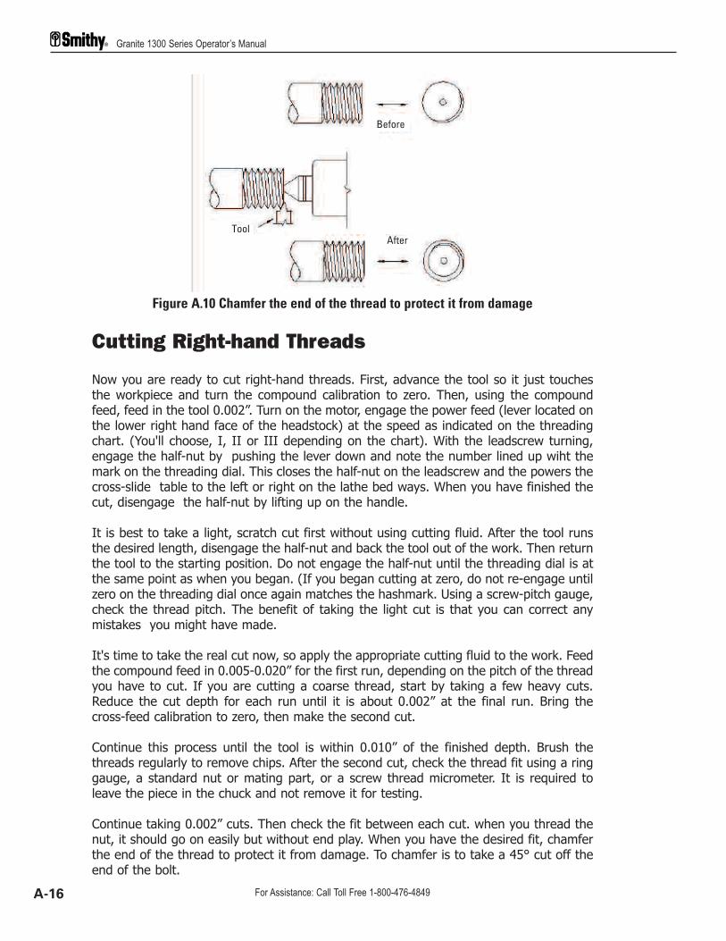
Cutting Right-hand Threads
Now you are ready to cut right-hand threads. First, advance the tool so it just touchesthe workpiece and turn the compound calibration to zero. Then, using the compoundfeed, feed in the tool 0.002”. Turn on the motor, engage the power feed (lever located onthe lower right hand face of the headstock) at the speed as indicated on the threadingchart. (You'll choose, I, II or III depending on the chart). With the leadscrew turning,engage the half-nut by pushing the lever down and note the number lined up wiht themark on the threading dial. This closes the half-nut on the leadscrew and the powers thecross-slide table to the left or right on the lathe bed ways. When you have finished thecut, disengage the half-nut by lifting up on the handle.
It is best to take a light, scratch cut first without using cutting fluid. After the tool runsthe desired length, disengage the half-nut and back the tool out of the work. Then returnthe tool to the starting position. Do not engage the half-nut until the threading dial is atthe same point as when you began. (If you began cutting at zero, do not re-engage untilzero on the threading dial once again matches the hashmark. Using a screw-pitch gauge,check the thread pitch. The benefit of taking the light cut is that you can correct anymistakes you might have made.
It's time to take the real cut now, so apply the appropriate cutting fluid to the work. Feedthe compound feed in 0.005-0.020” for the first run, depending on the pitch of the threadyou have to cut. If you are cutting a coarse thread, start by taking a few heavy cuts.Reduce the cut depth for each run until it is about 0.002” at the final run. Bring thecross-feed calibration to zero, then make the second cut.
Continue this process until the tool is within 0.010” of the finished depth. Brush thethreads regularly to remove chips. After the second cut, check the thread fit using a ringgauge, a standard nut or mating part, or a screw thread micrometer. It is required toleave the piece in the chuck and not remove it for testing.
Continue taking 0.002” cuts. Then check the fit between each cut. when you thread thenut, it should go on easily but without end play. When you have the desired fit, chamferthe end of the thread to protect it from damage. To chamfer is to take a 45° cut off theend of the bolt.
Figure A.10 Chamfer the end of the thread to protect it from damage
Granite 1300 Series Operator’s Manual
A-16 For Assistance: Call Toll Free 1-800-476-4849
Before
ToolAfter
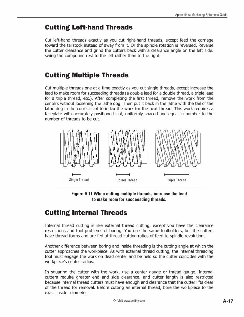
Cutting Left-hand Threads
Cut left-hand threads exactly as you cut right-hand threads, except feed the carriagetoward the tailstock instead of away from it. Or the spindle rotation is reversed. Reversethe cutter clearance and grind the cutters back with a clearance angle on the left side.swing the compound rest to the left rather than to the right.
Cutting Multiple Threads
Cut multiple threads one at a time exactly as you cut single threads, except increase thelead to make room for succeeding threads (a double lead for a double thread, a triple leadfor a triple thread, etc.). After completing the first thread, remove the work from thecenters without loosening the lathe dog. Then put it back in the lathe with the tail of thelathe dog in the correct slot to index the work for the next thread. This work requires afaceplate with accurately positioned slot, uniformly spaced and equal in number to thenumber of threads to be cut.
Cutting Internal Threads
Internal thread cutting is like external thread cutting, except you have the clearancerestrictions and tool problems of boring. You use the same toolholders, but the cuttershave thread forms and are fed at thread-cutting ratios of feed to spindle revolutions.
Another difference between boring and inside threading is the cutting angle at which thecutter approaches the workpiece. As with external thread cutting, the internal threadingtool must engage the work on dead center and be held so the cutter coincides with theworkpiece's center radius.
In squaring the cutter with the work, use a center gauge or thread gauge. Internalcutters require greater end and side clearance, and cutter length is also restrictedbecause internal thread cutters must have enough end clearance that the cutter lifts clearof the thread for removal. Before cutting an internal thread, bore the workpiece to theexact inside diameter.
Figure A.11 When cutting multiple threads, increase the lead to make room for succeesding threads.
Appendix A: Machining Reference Guide
A-17Or Visit www.smithy.com
Single Thread Double Thread Triple Thread

Because the feed of successive cuts is toward, not away from the operator, thethread-cutting set is reversed. Also, you must take lighter cuts because of the cutter'sextension from the toolpost. Take an extra finishing cut without changing the setting ofthe compound rest.
Cutting Special-form Internal Threads
You can cut internal forms in all the thread forms used for external threads. There is onlyone factor that calls for special attention in cutting special-shaped internal threads: thedifference of clearances between the nut and screw recommended for different threadtypes. If you don't have recommended clearances, it is safe to cut a nut (internal thread)thread 0.005” to 0.010” per inch larger than the screw's outside diameter.
Cutting Threads on a Taper
Cut thread on a taper the same as on a straight shaft, except in the setup of the tools.set the threading tool at 90° to the axis of the taper, rather than at 90° to its surface.
Granite 1300 Series Operator’s Manual
A-18 For Assistance: Call Toll Free 1-800-476-4849

Appendix BInch Feed Rates
Inch threadsare defined asthe number of
threads in one inch.
Metric threads aredefined as the dis-tance between two
adjacent crests.
METRICTHREADSINCH THREADS
”Longitudinal Feed Cross FeedFEED RATES =
I II III I II III
0.0197” 0.0098” 0.0049” 0.0062” 0.0031” 0.0015”
0.0172” 0.0086” 0.0043” 0.0054” 0.0027” 0.0014”
0.0153” 0.0076” 0.0038” 0.0048” 0.0024” 0.0012”
0.0137” 0.0069” 0.0034” 0.0043” 0.0022” 0.0011”
0.0125” 0.0062” 0.0031” 0.0039” 0.0020” 0.0010”
0.0115” 0.0057” 0.0029” 0.0036” 0.0018” 0.0009”
0.0106” 0.0053” 0.0026” 0.0033” 0.0017” 0.0008”
Distance traveled perSpindle Revolution
”
I II III I II III
0.70 0.35 3.50 1.75
0.80 0.40 4.00 2.00 1.00
0.45 4.50
1.00 0.50 5.00 2.50 1.25
5.50 2.75
0.60 6.00 3.00 1.50
6.50 3.25
I II III
7 14 28
8 16 32
9 18 36
10 20 40
11 22 44
12 24 48
13 26 52
1
2
3
4
5
6
7
GearSelection
X = Teeth per gear A = 30 B = 66 C = 60 D = 60A = 33 C = 63B = 80 D = 60
A = 66 C = 63B = 64 D = 60
SelectorI - III
SELECTOR
1-7
Lever locatedinside Pully Box
below gear cluster I N C H INCHM E T R I C METRIC
THREADINGCHART
B-1Or Visit www.smithy.com

Machine Warranty30 Day Trial Offer
Try a Smithy for 30 days. If, for any reason within that time, you decide to return yourSmithy, just call our Customer Service department at 1-800-476-4849. We will help youarrange shipping back to us. When we receive the machine back, we’ll refund your fullpurchase price. Please note: return shipping charges and any shipping damage fromimproper repacking is your responsibility.
Smithy Warranty
Smithy 3-in-1 and Dedicated Machines are warranted for two years (unless otherwisenoted)to the original purchaser against defects in materials and workmanship. Duringthat time, Smithy will replace any defective parts that are returned to our warehouse, freeof charge. Upon receipt of the defective parts, Smithy technicians will arrange with youto send replacement parts immediately. This warranty does not cover parts that are wornout through the negligence on the part of the operator nor does it cover consequentialdamages resulting from defects in material or workmanship.
SmithyCNC warrants its machines and control systems for a period of one (1) year to theoriginal purchaser from the date of purchase. If within one (1) year form the date ofpurchase a SmithyCNC machine and/or control system fails due to defect in material orworkmanship, SmithyCNC will at their choice repair and/or replace components with newor remanufactured parts free of charge.
(Some have asked why SmithyCNC machines have a shorter warranty period than Smithymanual machines. There are several reasons, but the greatest factor is that, on average,CNC automated machine tools, are operated a significantly greater number of hours perday than the average manual machine. Also, by comparison, most of our competitorsselling benchtop CNC machines only offer a six (6) months warranty. Whereas SmithyCNCmachine have a full one (1) year warranty.)
Most warranty repairs and/or replacements are handled routinely, but sometimes requestfor warranty service many not be appropriate. This warranty does not apply to defectsdue directly or indirectly to misuse, abuse, negligence, accidents, repairs, or lack ofroutine maintenance. This warranty is also void if the serial number of the machine orSmithyCNC control system has been removed or has been altered or modified.
In no event shall Smithy be liable for indirect, incidental or consequential damages for thesale or use of the product. This disclaimer applies to both during and after the term ofthis warranty.
C-1 For Assistance: Call Toll Free 1-800-476-4849

We do not warrant or represent that the merchandise complies with the provisions of anylaw or acts unless Smithy Company so warrants. In no event shall Smithy's liability underthis warranty exceed the purchase price paid for the product. Legal actions broughtagainst Smithy Co. shall be tried in the State of Michigan, County of Washtenaw.
Smithy Co. shall in no event be liable for death, injuries to persons or property forincidental, contingent, special or consequential damages arising from the use of ourproducts.
This is Smithy Co.’s sole warranty and any and all warranties that may be implied by law,including any merchantability or fitness, for any particular purpose, are hereby limited tothe duration of this written warranty.
This warranty gives you specific legal rights, and you may also have other rights, whichvary from state to state. Some states do not allow the exclusion or limitation ofincidental or consequential damages, so the above limitation or exclusions may not applyto you.
Telephone Support (Service engineers are available 8 am to 5 pm EST)
Service and Parts
Tel No. 1-800-476-4849Fax No. 1-734-913-6663Email Address: [email protected]
Software and Programming Consultancy Services
In addition to our customary technical support for the machines and controls, we alsoprovide technical consulting support to our customers by providing engineering and G-code programming services. The standard rate for these services is $28.00 per hour. Ourprincipal objective is to support you and to increase your productivity while reducing themachining cost. Give us a call for such support as and when required.
Tel No. 1-800-476-4849Fax No. 1-734-913-6663Email Address: [email protected]
C-2Or Visit www.smithy.com