globally controlled multiple relays using node mcu · this is to certify that the project work...
TRANSCRIPT
Globally controlled multiple relays using NODE MCU
A Project report submitted in partial fulfillment of the requirements for the degree of B. Tech in Electrical Engineering
by
KUNDAN GHOSH (11701614025) MONIDIP BHOWMICK (11701614028) DIPANWITA JODDAR (11701614020)
Under the supervision of
Mr. Budhaditya Biswas Assistant Professor
Department of Electrical Engineering
Department of Electrical Engineering
RCC INSTITUTE OF INFORMATION TECHNOLOGY CANAL SOUTH ROAD, BELIAGHATA, KOLKATA – 700015, WEST BENGAL
Maulana Abul Kalam Azad University of Technology (MAKAUT) © 2018

To
o heelp

Department of Electrical Engineering RCC INSTITUTE OF INFORMATION TECHNOLOGY
CANAL SOUTH ROAD, BELIAGHATA, KOLKATA – 700015, WEST BENGAL PHONE: 033-2323-2463-154, FAX: 033-2323-4668
Email: [email protected], Website: http://www.rcciit.org/academic/ee.aspx
CERTIFICATE
To whom it may concern
This is to c ertify that the project work entitle d Globally Controlled multiple relays using NODE MCU is the bonafide work carried out by Kundan Ghosh (11701614025), Monidip Bhowmick (11701614028) and Dipanwita Joddar (11701614020), the students of B.Tech in the Department of Electrical Engineering, RCC Institute of Information Technology (RCCIIT), Canal South Road, Beliaghata, K olkata-700015, affiliated to Maulana Abul Kalam Azad University of Technology (MAKAUT), West Bengal, India, during the academic year 2016-17, in partial fulfillment of the requirements for the degree of Bachelor of Technology in Electrical Engineering and that this project has not su bmitted previously f or the award of any other degree, diploma and fellowship.
(Budhaditya Biswas) Assistant Professor
Department of Electrical Engineering RCC Institute of Information Technology
Countersigned by
(Dr. Alok Kole) HOD, Electrical Engineering Dept (External Examiner) RCC Institute of Information Technology

ACKNOWLEDGEMENT
It is our great fortune that we have got opportunity to carry out t his project work under the supervision of Mr. Budhaditya Biswas in the Department of Electrical Engineering, RCC Instit ute of Inform ation Technology (RCCIIT), Canal South Road, Beliaghata, Kolkata-700015, affilia ted to Maulana Abul Kalam Azad University of Technology ( MAKAUT), West Bengal, Indi a. We express our sincere thanks and deepest sense of gratitude to our guide for his constant support, unparalleled guidance and limitless encouragement. We would also like to convey our gratitude to all the faculty mem bers and staffs of the Department of Electrical Engin eering, RCCIIT for their whole hearted cooperation to make this work turn into reality. We are v ery thankful to our Department and t o the authority of R CCIIT for providing all kinds of infrastructural facility towards the research work. Thanks to the fellow members of our group for working as a team.
KUNDAN GHOSH (11701614025) MONIDIP BHOWMICK (11701614028) DIPANWITA JODDAR (11701614020)

To The Head of the Department Department of Electrical Engineering RCC Institute of Information Technology Canal South Rd. Beliagahata, Kolkata-700015 Respected Sir,
In accordance with th e requirements of the degree of Bachelor of Technology in th e
Department of Electrical Engineerin g, RCC Ins titute of Information Technology, We presen t
the following thesis entitled “ Globally controlled multiple relays using NODE MCU”. This
work was perform ed under the valuable guid ance of Mr. Budhadtiya Biswas, Assistant
Professor in the Dept. of Electrical Engineering.
We declare that th e thesis submitted is our own, expected as acknowledge in the test and
reference and has not been previously submitted for a degree in any other Institution.
Yours Sincerely,
KUNDAN GHOSH (11701614025) MONIDIP BHOWMICK (11701614028) DIPANWITA JODDAR (11701614020)

Contents
Topic Page No. List of figures i
List of tables ii
Abbreviations and acronyms iii
Abstract iv
Chapter 1 (Introduction)
Introduction 2
1.1 Home Automation 2
1.2 Overview & Benefits 3
1.3 Organization of Thesis 4
Chapter 2 (Literature Review) 5
Chapter 3 (Theory)
3.1 IoT (Internet of Things) 9
3.1.1 IoT – Key Features 9
3.1.2 IoT – Advantages 9
3.1.3 IoT - Disadvantages 10
3.1.4 IoT Software 10
3.1.5 IoT – Technology and Protocols 11
3.1.6 IoT common uses 12
3.2 Node MCU 13
3.2.1 Pin Configuration of Node MCU Dev Board 13
3.2.2 Installation of Node MCU and coding 14
3.2.3 Interfacing of Node MCU with Arduino IDE 15
3.2.4 aREST Frameworks 17
3.3 Overview of the projects 18
3.4 Circuit Diagram 19
Chapter 4 (Hardware modelling)
4.1 Main Features of the Prototype 22
4.2 Photographs of the prototype 22
4.3 Step by step operation of the prototype 23
4.4 Components Required 24
4.5 Hardware Interfacing 25
4.5.1 Relay Driver Interfacing with µC 25
Chapter 5 (Logic & Operation)
5.1 Introduction 27
5.2 Flow chart 27
5.3 Principle & operations 28
5.4 Advantages of the NODE MCU 28
5.5 Disadvantages 28
5.6 Cost estimation of the project 29
5.7 Photographs of the prototype 29
Chapter 6 (Conclusion & Future scope)
6.1 Conclusion 34
6.2 Results 34
6.3 Future works 34
Chapter 7 (Reference) 35
Appendix A (Hardware Description) 37 – 44
Appendix B (Software Coding) 45 – 47
Appendix C (Datasheets) 48

List of Figures
Sl. No. Figure numbers Page No.
1 Concept of home automation 2 2 NODE MCU Development Board 13 3 NODE MCU with inbuilt wifi module 13 4 NODE MCU pin configuration 14 5 Snapshot of the installation process of NODE MCU 15 6 Driver installation for NODE MCU 15 7 Arduino IDE preferences 16 8 Arduino IDE board manager installation 169 ESP 8266 board installation in Arduino 17 10 NODE MCU interfacing with Arduino 17 11 Snapshot of aREST framework 18 12 Account creation and generation of unique API key in
aREST server 18
13 Working process of globally controlled relays 19 14 Connection diagram of the project 19 15 Screenshot of dashboard server 20 16 Main Controller and Relay board 22 17 ULN2003A interfacing with microcontroller 2518 Flowchart of the program 27 19 Main Controller Board 29 20 The Relay Board 30 21 The SMART Home 30 22 Different messages on the LCD 31 23 Complete setup of the project 32 24 Two different user interface for controlling the load 32 25 Transformer less SMPS 5volt power supply 38 26 ULN2003A internal block diagram 39 27 Resistor 39 28 Colour Code for resistance 40 29 6 volt Cube Relay 41 30 Types of capacitors 42 31 Crystal Oscillator 43 32 Pizeo Buzzer 43 33 Blank Glass Epoxy PCB Board 44
i

List of Tables
Sl. No. Table Page No.
1 Node MCU index ↔ GPIO mapping 14 2 Component Listing 24 3 Cost estimation of the project 29
ii
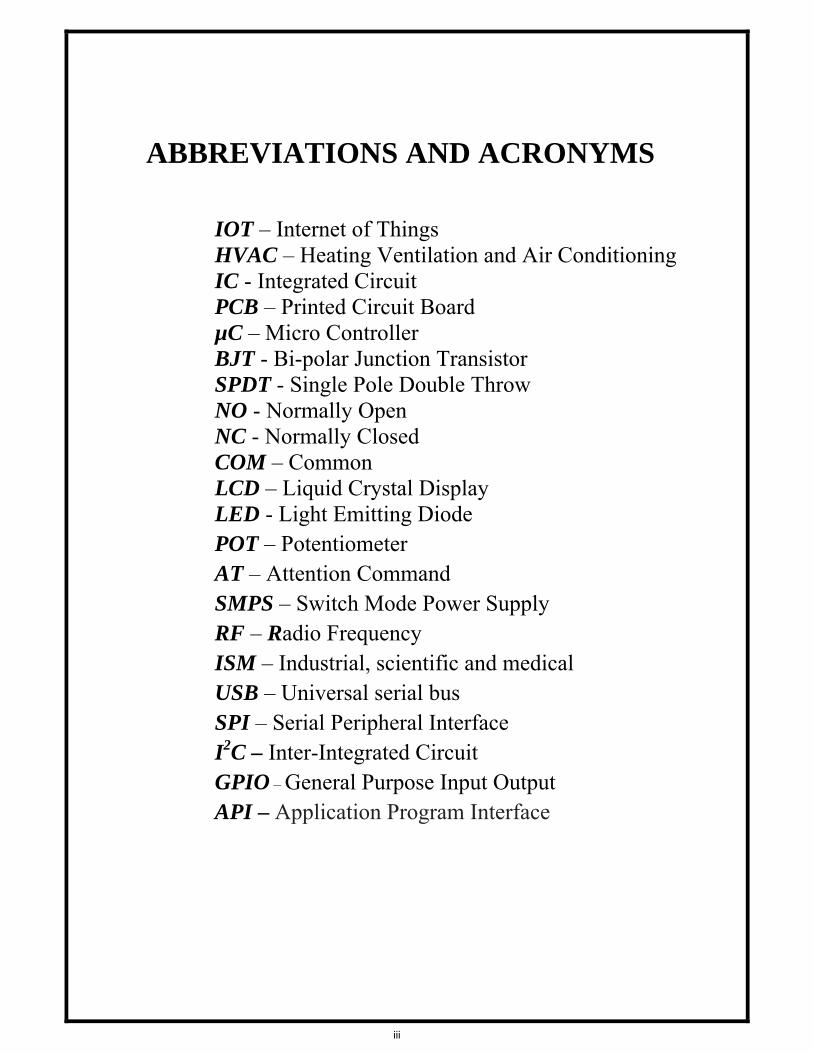
ABBREVIATIONS AND ACRONYMS
IOT – Internet of Things HVAC – Heating Ventilation and Air Conditioning IC - Integrated Circuit PCB – Printed Circuit Board µC – Micro Controller BJT - Bi-polar Junction Transistor SPDT - Single Pole Double Throw NO - Normally Open NC - Normally Closed COM – Common LCD – Liquid Crystal Display LED - Light Emitting Diode POT – Potentiometer AT – Attention Command SMPS – Switch Mode Power Supply RF – Radio Frequency ISM – Industrial, scientific and medical USB – Universal serial bus SPI – Serial Peripheral Interface I2C – Inter-Integrated Circuit GPIO – General Purpose Input Output
API – Application Program Interface
iii

ABSTRACT
Traditionally electrical appliances in a home are controlled via switches that regulate the electricity to these devices. As the world gets more and more technologically advanced, we find new technology coming in deeper and deeper into our personal lives even at home. Home automation is becoming more and more popular around the world and is becoming a common practice. The process of home automation works by making everything in the house automatically controlled using technology to control and do the jobs that we would normally do manually. Home automation takes care of a lot of different activities in the house.
The project proposes an efficient implementation for IoT (Internet of Things) used for monitoring and controlling the home appliances via World Wide Web. Home automation system uses the portable devices as a user interface. They can communicate with home automation network through an Internet gateway, by means of low power communication protocols like Zigbee, Wi-Fi etc. This project aims at controlling home appliances via web browser using Wi-Fi as communication protocol and node MCU as server system. The user here will move directly with the system through a web-based interface over the web, whereas home appliances like lights, fan etc are remotely controlled through easy website. The server will be interfaced with relay hardware circuits that control the appliances running at home. The server communicates with the corresponding relays. If the web affiliation is down or the server isn't up, the embedded system board still will manage and operate the appliances domestically. By this we provide a climbable and price effective Home Automation system
iv

CHAPTER 1
(Introduction)
Page 1

INTRODUCTION The project proposes an efficient implementation for IoT (Internet of Things) used for monitoring and controlling the home appliances via World Wide Web. Home automation system uses the portable devices as a user interface. They can communicate with home automation network through an Internet gateway, by means of low power communication protocols like Zigbee, Wi-Fi etc. This project aims at controlling home appliances via web browser using Wi-Fi as communication protocol and node MCU as server system.
NodeMCU is an open source IoT platform. The user here will move directly with the system through a web-based interface over the web, whereas home appliances like lights, fan etc are remotely controlled through easy website. The server will be interfaced with relay hardware circuits that control the appliances running at home. The server communicates with the corresponding relays. 1.1 HOME AUTOMATION
Home automation is the residential extension of building automation. It is automation of the home, housework or household activity. Home automation may include centralized
Figure 1: Concept of Home Automation
control of lighting, HVAC (heating, ventilation and air conditioning), appliances, security locks of gates and doors and other systems, to provide improved convenience, comfort, energy efficiency and security. Home automation for the elderly and disabled can provide increased quality of life for persons who might otherwise require caregivers or institutional care.
Page 2
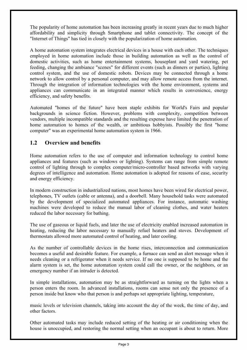
The popularity of home automation has been increasing greatly in recent years due to much higher affordability and simplicity through Smartphone and tablet connectivity. The concept of the "Internet of Things" has tied in closely with the popularization of home automation.
A home automation system integrates electrical devices in a house with each other. The techniques employed in home automation include those in building automation as well as the control of domestic activities, such as home entertainment systems, houseplant and yard watering, pet feeding, changing the ambiance "scenes" for different events (such as dinners or parties), lighting control system, and the use of domestic robots. Devices may be connected through a home network to allow control by a personal computer, and may allow remote access from the internet. Through the integration of information technologies with the home environment, systems and appliances can communicate in an integrated manner which results in convenience, energy efficiency, and safety benefits.
Automated "homes of the future" have been staple exhibits for World's Fairs and popular backgrounds in science fiction. However, problems with complexity, competition between vendors, multiple incompatible standards and the resulting expense have limited the penetration of home automation to homes of the wealth, or ambitious hobbyists. Possibly the first "home computer" was an experimental home automation system in 1966.
1.2 Overview and benefits
Home automation refers to the use of computer and information technology to control home appliances and features (such as windows or lighting). Systems can range from simple remote control of lighting through to complex computer/micro-controller based networks with varying degrees of intelligence and automation. Home automation is adopted for reasons of ease, security and energy efficiency.
In modern construction in industrialized nations, most homes have been wired for electrical power, telephones, TV outlets (cable or antenna), and a doorbell. Many household tasks were automated by the development of specialized automated appliances. For instance, automatic washing machines were developed to reduce the manual labor of cleaning clothes, and water heaters reduced the labor necessary for bathing.
The use of gaseous or liquid fuels, and later the use of electricity enabled increased automation in heating, reducing the labor necessary to manually refuel heaters and stoves. Development of thermostats allowed more automated control of heating, and later cooling.
As the number of controllable devices in the home rises, interconnection and communication becomes a useful and desirable feature. For example, a furnace can send an alert message when it needs cleaning or a refrigerator when it needs service. If no one is supposed to be home and the alarm system is set, the home automation system could call the owner, or the neighbors, or an emergency number if an intruder is detected.
In simple installations, automation may be as straightforward as turning on the lights when a person enters the room. In advanced installations, rooms can sense not only the presence of a person inside but know who that person is and perhaps set appropriate lighting, temperature,
music levels or television channels, taking into account the day of the week, the time of day, and other factors.
Other automated tasks may include reduced setting of the heating or air conditioning when the house is unoccupied, and restoring the normal setting when an occupant is about to return. More
Page 3

sophisticated systems can maintain an inventory of products, recording their usage through bar codes, or an RFID tag, and prepare a shopping list or even automatically order replacements.
Home automation can also provide a remote interface to home appliances or the automation system itself, to provide control and monitoring on a Smartphone or web browser.
An example of remote monitoring in home automation could be triggered when a smoke detector detects a fire or smoke condition, causing all lights in the house to blink to alert any occupants of the house to the possible emergency. If the house is equipped with a home theater, a home automation system can shut down all audio and video components to avoid distractions, or make an audible announcement. The system could also call the home owner on their mobile phone to alert them, or call the fire department or alarm monitoring company.
1.3 Organisation of thesis
The thesis is organised into five chapters including the chapter of introduction. Each chapter is different from the other and is described along with the necessary theory required to comprehend it.
Chapter 2 deals with the literature reviews. From this chapter we can see before our project who else works on this topic and how our project is different and advance from those projects. Chapter 3 deals with the theory required to do the project. The basic of operation of NODE MCU and the required connections. Chapter 4 deals with the hardware modelling of the projects. The main features, photographs, step by step operation of the prototype, component listing and the hardware interfacing of the required components are described here. Chapter 5 describes the basic operation of the circuit. A flow chart is presented on the actions that would take in the programming the NODE MCU with help of Audrino and to connect the device to aREST for controlling it globally. Chapter 6 concludes the work performed so far. The possible limitations in proceeding research towards this work are discussed. The future work that can be done in improving the current scenario is mentioned. The future potential along the lines of this work is also discussed.
Chapter 7 References are listed in this chapter
Appendix A, B & C Hardware description, software coding and datasheets are listed here.
Page 4

CHAPTER 2 (Literature Review)
Page 5

The system proposed in [1] uses stable communication plays an important role in autonomous applications with mobile robots, especially in the environments without communication infrastructures. There are high demands for quickly building wireless communication network for robots. To ensure stable wireless communication, the bottleneck of the data transmission is needed eliminating to make the communication ability best amongst base station, mobile robots and clients. The paper proposes an efficient approach to address the problem, by equipping WiFi routers on robots to enable and enhance communication ability. The system proposed in [2] develops home automation to improves the lifestyle of the control of home devices. Technology advancements have made the implementation of embedded systems within home appliances. The abilities and benefits are increased by the home automation. The value of our lives can be improved by automating various instruments or electrical appliances. The system proposed in [3] makes every system to be automated in order to face new challenges in the present day situation. Automated systems have less manual operations, so that the flexibility, reliabilities are high and accurate. Hence every field prefers automated control systems. Especially in the field of electronics automated systems are doing better performance. Nowadays, there are lots of good-quality motor speed controls on the market. However, their costs are relatively high. A speed control with both low cost and good performance will be highly marketable, especially for small mobility applications. On the other hand, the wireless connectivity has a nature of low cost and less environmental limitations. The system proposed in [4] incorporates with today’s world has seen rapid and lucent spread of Android Devices. Any system, thus, developed which has support of the ubiquitous Android –enabled devices will be much appreciated. Our project is based on this idea along with the much-needed Automation System interfaced with the Android Systems. We have harnessed the easy-to-understand Android GUI to a constructive work whereby we see to it that the home is automated and energy is saved. This makes our home intelligent enough to save electricity, which is the need of the hour. We have elucidated this idea into realization with the help of Wi-Fi technology, which really offers easy and really much awaited Home Automation Systems (HASs). This system has an upper hand from other similar developments made with the technologies such as Bluetooth since it works on Wi-Fi. Thus we have offered a scalable and cost-effective Home Automation Systems (HASs). The system proposed in [5] means home automation is becoming popular due to its numerous benefits. Home automation refers to the control of home appliances and domestic features by local networking or by remote control. Artificial Intelligence provides us the framework to go real-time decision and automation for Internet of Things (IoT).The work
Page 6

deals with discussion about different intelligent home automation systems and technologies from a various features standpoint. The work focuses on concept of home automation where the monitoring and control operations are facilitating through smart devices installed in residential buildings. Heterogeneous homeautomation systems and technologies considered in review with central controller based (Arduino or Raspberry pi), web based, email based, Bluetooth-based, mobile-based, SMS based, ZigBee based, Dual Tone Multi Frequency-based, cloud-based and the Internet with performance. The system proposed in [6] indicates Mobile devices part of our day-to-day life from last few years. Consequently, providing facilities and security are becoming increasingly prominent features on mobile devices. In this paper, we have to developed a home automation system that interfaces with Android mobile devices. The mobile device and system can communicate with each other from long-range via Wi-Fi. The mobile application can be loaded and interfaces with system from any compatible device. Commands to ON/OFF electrical equipment like lights, fans, air conditioners etc at home or any organization can be sent easily and quickly from the mobile devices via a simple and comfortable GUI application, which is easy to use for the any normal users. The system then acts and responds to these commands by taking actions per commands and gives the result to the user. The user can also see the result on Android mobile application from anywhere. Therefore, it's a good choice to design a home automation for luxurious life.
The system proposed in [7] helps to make process of controlling or operating various equipment, machinery, industrial processes, and other applications using various control systems and also with less or no human intervention is termed as automation. There are various types of automation based on the application they can be categorized as home automation, industrial automation, autonomous automation, building automation, etc. In this article,
The system proposed in [8] turns the Internet of Things(IoT) into a hot topic in the present tech-driven world. Internet of Things is one of the promising technology used to control objects connected to Internet through IP address, which enables objects to collect and exchange data. Internet of Things is expanding itself into different areas. Home Automation is one of the trend in application of IoT for realizing smart cities. In the paper, we are developing a system which will control through MQTT protocol. MQTT has been utilized as a platform to provide IoT services which will monitor the applications and generate alerts or take intelligent decisions using concept of IoT. Nodemcu was used as aIoT end device connecting relays to the platform via wifi channel. Home scenario is created and designed IoT messages satisfying the scenario requirement. We also implemented Automation through HTML web page. A main contribution of this paper is that it summarizes uses of Intenet of Things in Home Automation with Artificial Intelligence to monitor and control the appliances.
Page 7

CHAPTER 3 (Theory)
Page 8

3.1 IoT (Internat of Things)
IoT (Internet of Things) is an advanced automation and analytics system which exploits networking, sensing, big data, and artificial intelligence technology to deliver complete systems for a product or service. These systems allow greater transparency, control, and performance when applied to any industry or system.
IoT systems have applications across industries through their unique flexibility and ability to be suitable in any environment. They enhance data collection, automation, operations, and much more through smart devices and powerful enabling technology.
3.1.1 IoT − Key Features
The most important features of IoT include artificial intelligence, connectivity, sensors, active engagement, and small device use. A brief review of these features is given below
AI − IoT essentially makes virtually anything “smart”, meaning it enhances every aspect of life with the power of data collection, artificial intelligence algorithms, and networks. This can mean something as simple as enhancing your refrigerator and cabinets to detect when milk and your favorite cereal run low, and to then place an order with your preferred grocer.
Connectivity − New enabling technologies for networking, and specifically IoT networking, mean networks are no longer exclusively tied to major providers. Networks can exist on a much smaller and cheaper scale while still being practical. IoT creates these small networks between its system devices.
Sensors − IoT loses its distinction without sensors. They act as defining instruments which transform IoT from a standard passive network of devices into an active system capable of real-world integration.
Active Engagement − Much of today's interaction with connected technology happens through passive engagement. IoT introduces a new paradigm for active content, product, or service engagement.
Small Devices − Devices, as predicted, have become smaller, cheaper, and more powerful over time. IoT exploits purpose-built small devices to deliver its precision, scalability, and versatility.
3.1.2 IoT − Advantages
The advantages of IoT span across every area of lifestyle and business. Here is a list of some of the advantages that IoT has to offer
Improved Customer Engagement − Current analytics suffer from blind-spots and significant flaws in accuracy; and as noted, engagement remains passive. IoT completely transforms this to achieve richer and more effective engagement with audiences.
Technology Optimization − The same technologies and data which improve the customer experience also improve device use, and aid in more potent improvements to technology. IoT unlocks a world of critical functional and field data.
Reduced Waste − IoT makes areas of improvement clear. Current analytics give us superficial insight, but IoT provides real-world information leading to more effective management of resources.
Page 9

Enhanced Data Collection − Modern data collection suffers from its limitations and its design for passive use. IoT breaks it out of those spaces, and places it exactly where humans really want to go to analyze our world. It allows an accurate picture of everything.
3.1.3 IoT − Disadvantages
Though IoT delivers an impressive set of benefits, it also presents a significant set of challenges. Here is a list of some its major issues
Security − IoT creates an ecosystem of constantly connected devices communicating over networks. The system offers little control despite any security measures. This leaves users exposed to various kinds of attackers.
Privacy − The sophistication of IoT provides substantial personal data in extreme detail without the user's active participation.
Complexity − Some find IoT systems complicated in terms of design, deployment, and maintenance given their use of multiple technologies and a large set of new enabling technologies.
Flexibility − Many are concerned about the flexibility of an IoT system to integrate easily with another. They worry about finding themselves with several conflicting or locked systems.
Compliance − IoT, like any other technology in the realm of business, must comply with regulations. Its complexity makes the issue of compliance seem incredibly challenging when many consider standard software compliance a battle.
3.1.4 Iot Software IoT software addresses its key areas of networking and action through platforms, embedded systems, partner systems, and middleware. These individual and master applications are responsible for data collection, device integration, real-time analytics, and application and process extension within the IoT network. They exploit integration with critical business systems (e.g., ordering systems, robotics, scheduling, and more) in the execution of related tasks.
Data Collection This software manages sensing, measurements, light data filtering, light data security, and aggregation of data. It uses certain protocols to aid sensors in connecting with real-time, machine-to-machine networks. Then it collects data from multiple devices and distributes it in accordance with settings. It also works in reverse by distributing data over devices. The system eventually transmits all collected data to a central server.
Device Integration Software supporting integration binds (dependent relationships) all system devices to create the body of the IoT system. It ensures the necessary cooperation and stable networking between devices. These applications are the defining software technology of the IoT network because without them, it is not an IoT system. They manage the various applications, protocols, and limitations of each device to allow communication.
Page 10

Real-Time Analytics These applications take data or input from various devices and convert it into viable actions or clear patterns for human analysis. They analyze information based on various settings and designs in order to perform automation-related tasks or provide the data required by industry.
Application and Process Extension These applications extend the reach of existing systems and software to allow a wider, more effective system. They integrate predefined devices for specific purposes such as allowing certain mobile devices or engineering instruments access. It supports improved productivity and more accurate data collection.
3.1.5 Internet of Things - Technology and Protocols
IoT primarily exploits standard protocols and networking technologies. However, the major enabling technologies and protocols of IoT are RFID, NFC, low-energy Bluetooth, low-energy wireless, low-energy radio protocols, LTE-A, and WiFi-Direct. These technologies support the specific networking functionality needed in an IoT system in contrast to a standard uniform network of common systems.
NFC and RFID
RFID (radio-frequency identification) and NFC (near-field communication) provide simple, lowenergy, and versatile options for identity and access tokens, connection bootstrapping, and payments.
RFID technology employs 2-way radio transmitter-receivers to identify and track tags associated with objects.
NFC consists of communication protocols for electronic devices, typically a mobile device and a standard device.
Low-Energy Bluetooth
This technology supports the low-power, long-use need of IoT function while exploiting a standard technology with native support across systems.
Low-Energy Wireless
This technology replaces the most power hungry aspect of an IoT system. Though sensors and other elements can power down over long periods, communication links (i.e., wireless) must remain in listening mode. Low-energy wireless not only reduces consumption, but also extends the life of the device through less use.
Radio Protocols
ZigBee, Z-Wave, and Thread are radio protocols for creating low-rate private area networks. These technologies are low-power, but offer high throughput unlike many similar options. This increases the power of small local device networks without the typical costs.
LTE-A
LTE-A, or LTE Advanced, delivers an important upgrade to LTE technology by increasing not only its coverage, but also reducing its latency and raising its throughput. It gives IoT a tremendous power through expanding its range, with its most significant applications being vehicle, UAV, and similar communication.
Page 11

WiFi-Direct
WiFi-Direct eliminates the need for an access point. It allows P2P (peer-to-peer) connections with the speed of WiFi, but with lower latency. WiFi-Direct eliminates an element of a network that often bogs it down, and it does not compromise on speed or throughput.
3.1.6 Internet of Things - Common Uses
IoT has applications across all industries and markets. It spans user groups from those who want to reduce energy use in their home to large organizations who want to streamline their operations. It proves not just useful, but nearly critical in many industries as technology advances and we move towards the advanced automation imagined in the distant future.
Engineering, Industry, and Infrastructure
Applications of IoT in these areas include improving production, marketing, service delivery, and safety. IoT provides a strong means of monitoring various processes; and real transparency creates greater visibility for improvement opportunities.
The deep level of control afforded by IoT allows rapid and more action on those opportunities, which include events like obvious customer needs, nonconforming product, malfunctions in equipment, problems in the distribution network, and more.
Government and Safety
IoT applied to government and safety allows improved law enforcement, defense, city planning, and economic management. The technology fills in the current gaps, corrects many current flaws, and expands the reach of these efforts. For example, IoT can help city planners have a clearer view of the impact of their design, and governments have a better idea of the local economy.
Home and Office
In our daily lives, IoT provides a personalized experience from the home to the office to the organizations we frequently do business with. This improves our overall satisfaction, enhances productivity, and improves our health and safety. For example, IoT can help us customize our office space to optimize our work.
Health and Medicine
IoT pushes us towards our imagined future of medicine which exploits a highly integrated network of sophisticated medical devices. Today, IoT can dramatically enhance medical research, devices, care, and emergency care. The integration of all elements provides more accuracy, more attention to detail, faster reactions to events, and constant improvement while reducing the typical overhead of medical research and organizations.
Page 12
3.2
NodeMCthe ESP8"NodeMCthe Lua scfor ESP82
NodeMCsystem beXtensa LX
The ESP8produced
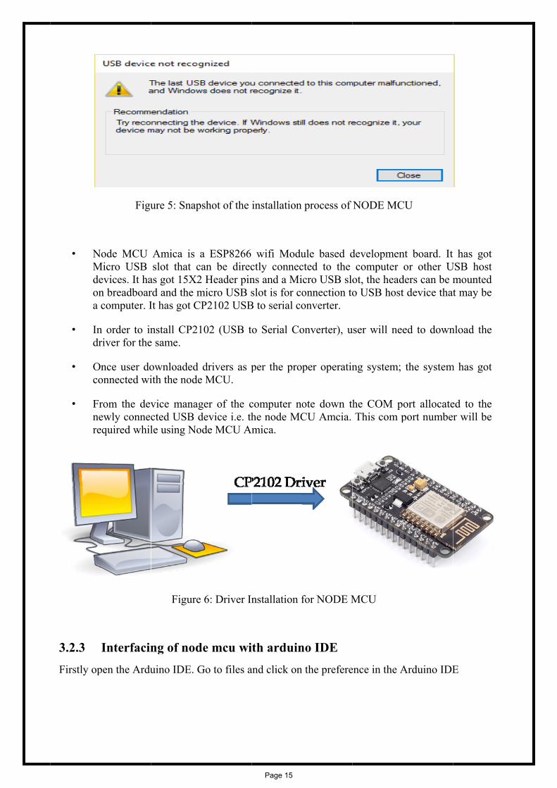
3.2.1 This modbased on the D0 piPlease ref
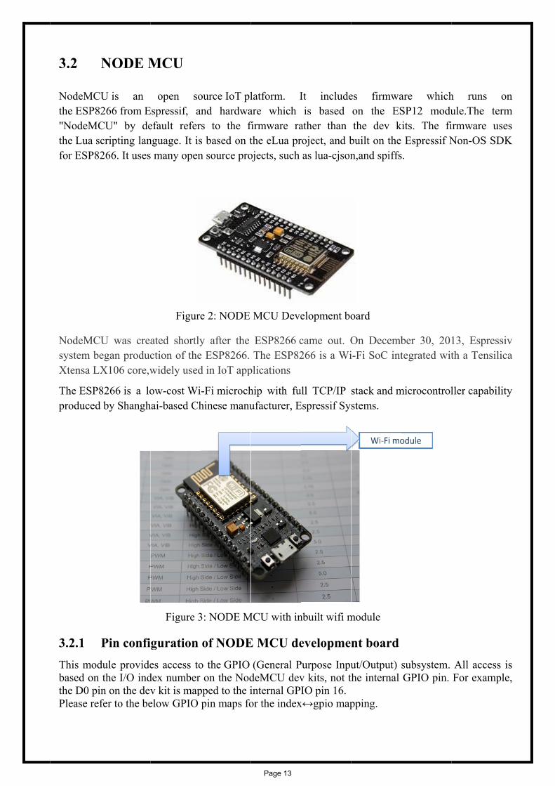
NODE M
U is an 266 from ECU" by decripting lan266. It uses
U was creaegan producX106 core,w
8266 is a lod by Shangh
Pin confidule providethe I/O indn on the devfer to the be
MCU
open soEspressif, aefault refernguage. It iss many open
ated shortlyction of thewidely used
ow-cost Wihai-based Ch
Figure 3
guration es access to
dex number v kit is mapelow GPIO
Figure
ource IoT pland hardwars to the fs based on tn source pro
y after thee ESP8266. d in IoT app
-Fi microchhinese manu
3: NODE M
of NODEo the GPIO
on the Nodpped to the ipin maps fo
e 2: NODE
latform. Iare which firmware rathe eLua projects, such
ESP8266 cThe ESP82
plications
hip with fuufacturer, E
MCU with in
E MCU de(General P
deMCU devinternal GPor the index
MCU Deve
It includeis based
ather than roject, and bas lua-cjson
came out. O266 is a Wi
ull TCP/IP Espressif Sy
nbuilt wifi m
evelopmePurpose Inpuv kits, not tIO pin 16.
x↔gpio map
elopment bo
es firmwaon the ESthe dev k
built on the n,and spiffs
On Decembi-Fi SoC int
stack and mstems.
module
nt board ut/Output) the internal
pping.
oard
are whichSP12 modu
kits. The fi Espressif N
s.
ber 30, 20tegrated wit
microcontrol
subsystem. GPIO pin.
h runs oule.The terirmware usNon-OS SD
13, Espressth a Tensili
ller capabili
All access For examp
on rm ses DK
siv ica
ity
is le,
Page 13
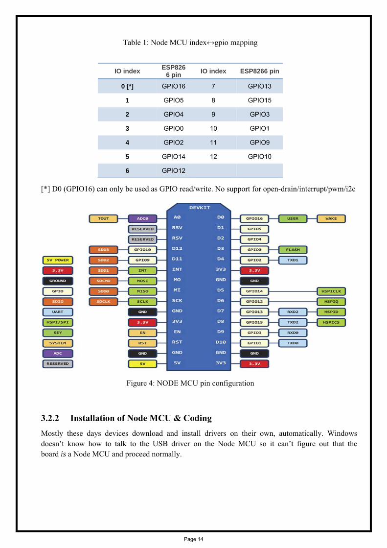
Table 1: Node MCU index↔gpio mapping
[*] D0 (GPIO16) can only be used as GPIO read/write. No support for open-drain/interrupt/pwm/i2c
Figure 4: NODE MCU pin configuration
3.2.2 Installation of Node MCU & Coding Mostly these days devices download and install drivers on their own, automatically. Windows doesn’t know how to talk to the USB driver on the Node MCU so it can’t figure out that the board is a Node MCU and proceed normally.
IO index ESP8266 pin IO index ESP8266 pin
0 [*] GPIO16 7 GPIO13
1 GPIO5 8 GPIO15
2 GPIO4 9 GPIO3
3 GPIO0 10 GPIO1
4 GPIO2 11 GPIO9
5 GPIO14 12 GPIO10
6 GPIO12
Page 14
• NMdeona
• Indr
• Oco
• Frnere
3.2.3 Firstly op
Figu
Node MCU Micro USB
evices. It han breadboarcomputer. I
n order to inriver for the
nce user doonnected wi
rom the devewly connecequired whil
Interfacinpen the Ardu
ure 5: Snap
Amica is aslot that ca
as got 15X2rd and the mIt has got CP
nstall CP21e same.
ownloaded ith the node
vice managcted USB dle using No
Figure
ng of noduino IDE. G
shot of the
a ESP8266 an be direc
2 Header pinmicro USB sP2102 USB
102 (USB t
drivers as pe MCU.
ger of the cdevice i.e. thde MCU Am
6: Driver In
de mcu wiGo to files a
installation
wifi Moductly connecns and a Mislot is for co
B to serial co
o Serial Co
per the pro
computer nohe node MCmica.
nstallation f
ith arduinand click on
process of
ule based dcted to the cro USB sloonnection toonverter.
onverter), u
per operatin
ote down thCU Amcia.
for NODE M
no IDE n the prefere
NODE MC
developmencomputer
ot, the heado USB host
user will nee
ng system;
he COM pThis com p
MCU
ence in the A
CU
nt board. It or other U
ders can be mt device that
ed to down
the system
ort allocateport numbe
Arduino IDE
has got USB host
mounted t may be
nload the
m has got
ed to the r will be
E
Page 15
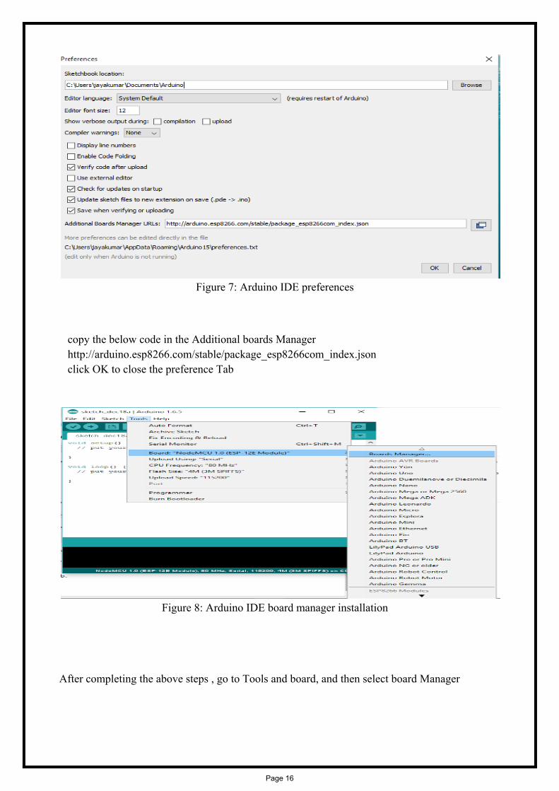
Figure 7: Arduino IDE preferences
copy the below code in the Additional boards Manager http://arduino.esp8266.com/stable/package_esp8266com_index.json click OK to close the preference Tab
Figure 8: Arduino IDE board manager installation
After completing the above steps , go to Tools and board, and then select board Manager
Page 16
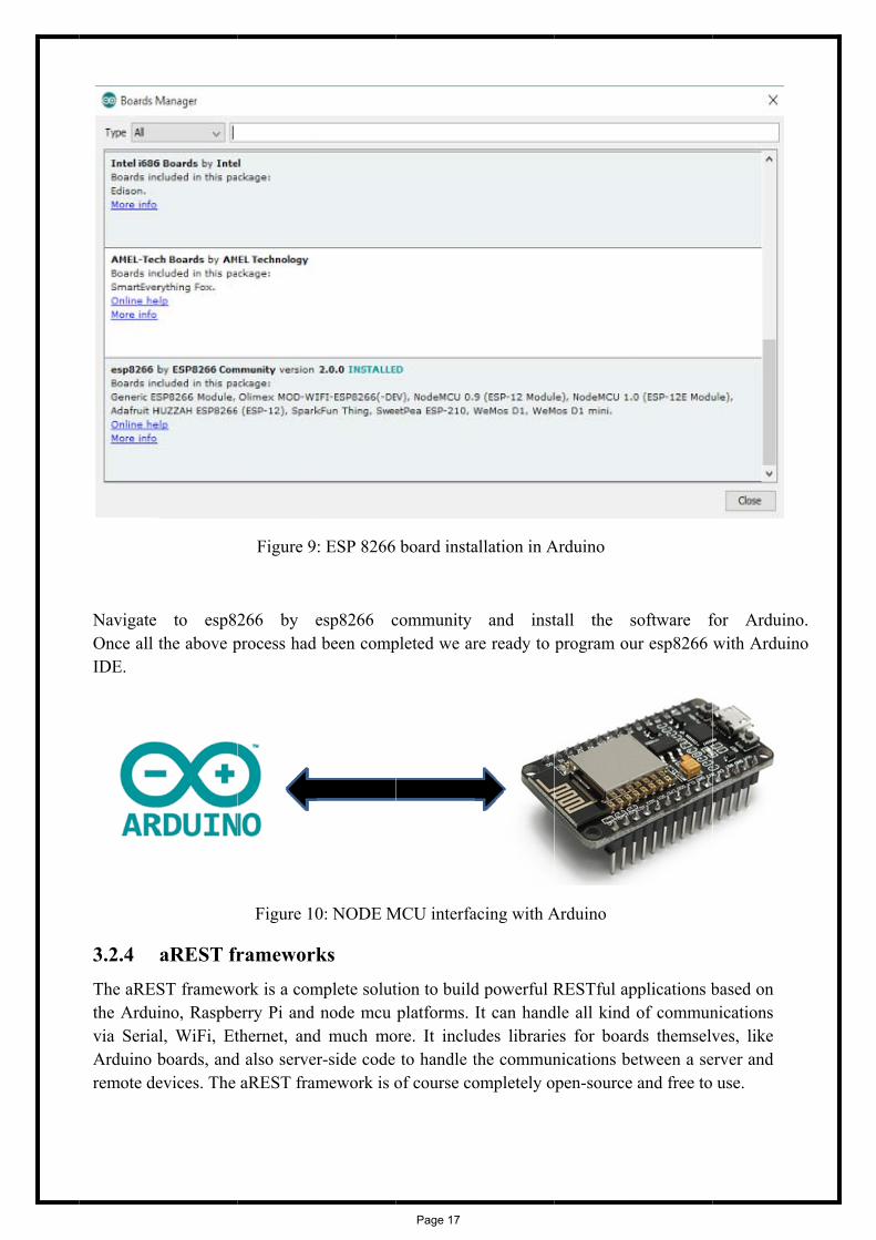
Navigate Once all IDE.
3.2.4 The aRESthe Arduivia SeriaArduino bremote de
to esp82the above p
aREST frST framewoino, Raspbe
al, WiFi, Etboards, andevices. The
Figure 9
266 by eprocess had
Figure 10
rameworkork is a comerry Pi and thernet, andd also server
aREST fram
: ESP 8266
esp8266 cbeen comp
0: NODE M
ks mplete solut
node mcu d much mor-side code mework is o
board insta
community pleted we ar
MCU interfa
tion to buildplatforms.
ore. It incluto handle t
of course co
allation in A
and instre ready to
acing with A
d powerful RIt can hand
udes librariethe communompletely o
Arduino
tall the sprogram ou
Arduino
RESTful apdle all kind es for boarnications be
open-source
software fur esp8266
pplications bof communds themselvetween a seand free to
for Arduinwith Arduin
based on nications ves, like
erver and use.
no. no
Page 17

3.3 The follounique Adevice in
F
Once the written inprocess is
Goto da
Acby
Overvieowing proceAPI key aga
the arrest s
Figure 12: A
unique APIn embeddeds described
ashboard.a
ccount crey a mail id a
An uniqdevice I
Thawri
Figur
ew of thess describeainst a partserver.
Account cre
I key is gend C for combelow.
arest.io
ated undeand passwo
que API keyD which w
at API Key itten in em
Thus aREprovides
re 11: Snaps
he projees how to crticular devi
eation and g
nerated the nmmunicatio
r dashboord
y is generawas provide
is put intombedded C
EST indents particular
shot of aRE
ect reate an accce. The AP
generation o
next step is
on between
oard.are
ated by theed to aRES
o the progrC
tifies the pr server fo
EST framew
count in dasPI key is th
of unique AP
to include the NODE
est.io
e unique ST
ram which
articular dor its work
work
shboard.arehe identifie
PI key in ar
that key in E MCU and
is
device and king
st.io and geer for the p
rest server
the coding d arest serv
enerate a particular
which is ver. The
Page 18

3.4
The NO
thein
Fig
Circuit
DE MCU sh
e SSID and pthe cooding
open das
creawit
gure 13: wo
Diagram
ould be con
password og
shboard.are
ate the ON/h proper GP
control thdashboar
Figure
orking proce
m
nnected thr
f the wifi sh
est.io and c
/OFF controPIO mentio
he relays cord
e 14: Conne
ess of the gl
rough wifi
hould be inc
reate a new
ol button in ned in the c
nnected wi
ection diagra
lobally cont
cluded
w dashboard
the dashbocooding
th the node
am of the pr
trolled relay
d
oard
e mcu from
roject
ys
Page 19

The Node MCU Device has a unique device ID. It is to be inserted into aREST.
A Unique API KEY from aREST is generated. That API Key is to be mentioned
into the embedded c program of Arduino. The program is burnt into NODE MCU.
Hence the NODE MCU is connected to aREST and it can be globally controlled
By signing into aREST.dashboard.com with help of log in id and password.
Figure 15: Screenshot of the dashboard server
Page 20

CHAPTER 4
(Hardware Modelling)
Page 21

4.1 Main features of the prototype
The features of the developed prototype are:
Globally controlled (throughout the world)
Real time load status display in the web page
7 independent load control (250 volt, 7 amp max, ON/OFF control)
Inbuilt relay driver
Secure control
5 Volt operation (both control board and relay board)
Cost effective (approx. 650/-)
4.2 Photographs of the prototype
Figure 16: Main Controller and Relay board
Page 22

4.3
1.
2.
3. 4.
5. 6.
7.
Step by
Connect th
Enable thein the code
Power On Open the dcontrolled
login withOpen the d
In the pre-
step ope
he DC adap
e pre-specifie)
the circuit dashboard.a
d)
h user ID anddashboard t
-design user
eration o
pter (5V, 1A
fied wifi (kn
arest.io thro
d passwordab and click
r accessible
of the pr
A) to the DC
nown SSID
ough any br
d (secure) k on “globa
web page c
rototype
C jack.
and passwo
rowser using
ally controlle
check the st
ord mention
g any intern
ed relay”
tatus of the
ned
net connecti
circuit (mus
ion (globall
st be online
ly
e)
Page 23

8. Click the particular relay ON by clicking the ON button
9. Check the status of the relay by seeing the status mentioned in the web page (should be HIGH)
10. Click the particular relay OFF by clicking the OFF button 11. Check the status of the relay by seeing the status mentioned in the web page (should be
LOW).
4.4 Components required
Table 2: Component listing
Sl. No. Component Qtn 1. Node MCU 1 2. ULN 2003 A IC 1 3. Static Relay (5 volt) 7 4. 3 mm LED (Red/Green) 9 5. General blank PCB 1 6. Jumper wire 9 7. Single strand wire 3m 8. Wire nipper 1 9. Wire striper 1 10. Soldering Iron 1 11. Soldering material 1 12. De-soldering pump 1 13. Female pin header 1 14. Male pin header 1
Page 24

4.5 Hardware connection
4.5.1 Relay Driver interfacing with microcontroller
Figure 17: ULN2003A interfacing with microcontroller
The ULN2003A is a active high relay driver. 7 relays are controlled by this relay driver. Pin 1-7 are for controlling the relay which are connected to pin 10-16. For a ‘0’ from microcontroller the corresponding relay is turned off and a ‘1’ from microcontroller is turned on the relay.
Page 25

CHAPTER 5 (Logic & Operation)
Page 26

5.1 INTRODUCTION
After assembling the system, what remains is to observe its operation and efficiency of the system. The total system is divided in several sub systems, like
Node MCU Relay Board Relay
The operation of the whole circuit is depending on every sections performance.
5.2 Flow Chart
Figure 18: Flow chart of the program
START
MCU receive signal from server
NODE MCU is turned on and connected to preset wifi (known SSID and password)
Wait for aREST dashboard online
status Relay Board receive
signal from MCU
ON/OFF LOAD 1
ON/OFF LOAD 2
ON/OFF LOAD 3
ON/OFF LOAD 4
ON/OFF LOAD 5
ON/OFF LOAD 7
ON/OFF LOAD 6
Page 27

5.3 Principle & Operations
NodeMCU is an open source IoT platform. It includes firmware which runs on the ESP8266 Wi-Fi SoC from Espressif Systems, and hardware which is based on the ESP-12 module. The term "NodeMCU" by default refers to the firmware rather than the development kits. The firmware uses the Lua scripting language. It is based on the eLua project, and built on the Espressif Non-OS SDK for ESP8266. It uses many open source projects, such as lua-cjson, and spiffs.
The aREST framework is a complete solution to build powerful RESTful applications based on the Arduino, Raspberry Pi and node mcu platforms. It can handle all kind of communications via Serial, WiFi, Ethernet, and much more. At first we have to create an account in dashboard.arest.in website. It is giving us a platform to control the load through relays globally. After that an API Key is generated for that particular account. It is given to our main program and the device ID is attached with it.
On the other hand, Node MCU is to be connected with host device. When a Signal is given to Node MCU for controlling any of appliances(i.e. Electrical Loads) the particular Relay Switch which is connected to particular load to be controlled(ON/OFF) is getting signal from Node MCU and it is turned on as well as the load is switched on.
5.4 Advantages of the NODE MCU
Low cost : The Node MCU is less costlier than any other IOT based Devices. Because the wifi module which is used in it is of lowest cost.
Hardware Part: It has Arduino Like hardware I/O. It is becoming very popular in these
days that Arduino IDE has extended their software to work in the field of ESP 8266 Field module version.
Network API: Node MCU has easily configurable network API.
Integrated Wifi Module: ESP 8266 is incorporated in NODE MCU.It is an easily accessible
wifi module.
5.5 Disadvantages
The operation of the circuit depends on the working internet connection. If the working
internet connection is not available then it will not run.
It also depends on the free server provided by the third party, if the free server is not
working then it will not run.
NODE MCU has less resources of official documentation
Page 28
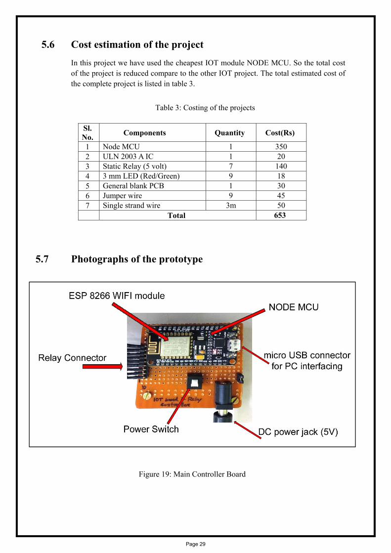
5.6 Cost estimation of the project In this project we have used the cheapest IOT module NODE MCU. So the total cost of the project is reduced compare to the other IOT project. The total estimated cost of the complete project is listed in table 3.
Table 3: Costing of the projects
Sl. No. Components Quantity Cost(Rs)
1 Node MCU 1 350 2 ULN 2003 A IC 1 20 3 Static Relay (5 volt) 7 140 4 3 mm LED (Red/Green) 9 18 5 General blank PCB 1 30 6 Jumper wire 9 45 7 Single strand wire 3m 50 Total 653
5.7 Photographs of the prototype
Figure 19: Main Controller Board
Page 29

Figure 20: The Relay Board
Figure 21: The SMART Home
Page 30

Figure 22: Different messages on the LCD
Page 31

Figur
Fig
re 24: Two
gure 23: Co
different us
omplete setu
ser interface
up of the Pro
e for control
oject
lling the loaad
Page 32

Chapter 6 (Conclusion & Future Scope)
Page 33

6.1 CONCLUSION
Here we have used NODEMCU which has inbuilt wifi module to control relays locally as well as globally. It is one of the easiest and most pocket friendly home automation control system based on IOT. The project proposes an efficient implementation for IoT (Internet of Things) used for monitoring and controlling the home appliances via World Wide Web. Home automation system uses the portable devices as a user interface. They can communicate with home automation network through an Internet gateway, by means of low power communication protocols like Zigbee, Wi-Fi etc. The user here will move directly with the system through a web-based interface over the web, whereas home appliances like lights, fan etc are remotely controlled through easy website. The server will be interfaced with relay hardware circuits that control the appliances running at home. The server communicates with the corresponding relays. If the web affiliation is down or the server isn't up, the embedded system board still will manage and operate the appliances domestically. By this we provide a climbable and price effective Home Automation system
6.2 RESULTS The experimental model was made according to the circuit diagram and the results were as expected. The loads are switched on when the NODE MCU gets the signal correctly from aREST and it drives the particular load relay correctly. The loads are switched off only when the NODE MCU gets the OFF signal from aREST i.e. from the user. 6.2 FUTURE SCOPE As we have already mentioned in the disadvantage of the prototype that the working of the circuit is depend on a third party server “aRest”. If the server will not work then the prototype is also not work. So our future plan is to build our own server so that we ensure that the working of the prototype will continues all the time.
Page 34

Chapter 7 (References)
Page 35

1 Yanjun Gao,H.Chen,Y.Li. “AUTONOMOUS WIFI RELAY CONTROL WITH MOBILE ROBOTS”,RCAR, 6-10 June ,2016.
2 N.S. Mubina , A. Anandhaveli, Bharati, “SMART HOME AUTOMATION CONTROL USING BLUETOOTH AND GSM”,IJIFR,8th March,2015, P-P 2547-2552.
3 ParthaSarathi, M.B. Patel,S.J. Bora,B.U. Parihar,” WIRELESS BASED D.C. MOTOR SPEED CONTROL USING ZIGBEE.”, IOSR-JCE, PP32-35. 2016.
4 Prof.R.S. Suryavanshi, Kunal Khivensara, G. Hussain, N. Bansal,V .Kumar,”HOME AUTOMATION SYSTEM USING ANDROID AND WIFI”, International Journal and Engnieering, 10th Oct 2014, PP-8792-8794.
5 Prof. A. Kumar, P.Kumar, R.Gupta,”HOME AUTOMATION: WIFI CONTROLLED RELAY.”, March 2015 Vol-2, PP-270-273
6 Prof. J. Dandge, R. Sridhwar,P.Gite,N.Odhekar,C. Kakad,”ELECTRIC SWITCH ON OFF SYSTEM USING ANDROID APP VIA WIFI.”, International Research Journal Of Engineering And Technology. Vol-3 issued Mar-2016. P.No-2395-0072.
7 Govind Prasad Arya, A. Mumtaz, S.Ghildiyal, “WIRELESS HOME APPLIANCE CONTROL USING IOT.”,IJCA(0975-8887),Vol-168-No.2,June 17.
8 C.Sekhar,N.Kumar,Raju K.N.,Sanjay N.,Chandrappa, “INTERNET OF THINGS BASED AUTOMATION USING ARTIFICIAL INTELLIGENCE.”,IJOERMNT,Vol-6,July 2017,P.No.-142-145
Page 36

Appendix A (Hardware description)
Page 37
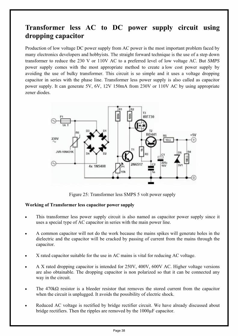
Transformer less AC to DC power supply circuit using dropping capacitor Production of low voltage DC power supply from AC power is the most important problem faced by many electronics developers and hobbyists. The straight forward technique is the use of a step down transformer to reduce the 230 V or 110V AC to a preferred level of low voltage AC. But SMPS power supply comes with the most appropriate method to create a low cost power supply by avoiding the use of bulky transformer. This circuit is so simple and it uses a voltage dropping capacitor in series with the phase line. Transformer less power supply is also called as capacitor power supply. It can generate 5V, 6V, 12V 150mA from 230V or 110V AC by using appropriate zener diodes.
Figure 25: Transformer less SMPS 5 volt power supply
Working of Transformer less capacitor power supply
This transformer less power supply circuit is also named as capacitor power supply since it uses a special type of AC capacitor in series with the main power line.
A common capacitor will not do the work because the mains spikes will generate holes in the dielectric and the capacitor will be cracked by passing of current from the mains through the capacitor.
X rated capacitor suitable for the use in AC mains is vital for reducing AC voltage.
A X rated dropping capacitor is intended for 250V, 400V, 600V AC. Higher voltage versions are also obtainable. The dropping capacitor is non polarized so that it can be connected any way in the circuit.
The 470kΩ resistor is a bleeder resistor that removes the stored current from the capacitor when the circuit is unplugged. It avoids the possibility of electric shock.
Reduced AC voltage is rectified by bridge rectifier circuit. We have already discussed about bridge rectifiers. Then the ripples are removed by the 1000µF capacitor.
Page 38

This circuit provides 24 volts at 160 mA current at the output. This 24 volt DC can be regulated to necessary output voltage using an appropriate 1 watt or above zener diode.
Here we are using 6.2V zener. You can use any type of zener diode in order to get the required output voltage.
Relay Driver
Figure 26: ULN2003A Internal Block Diagram
Resistor
Figure 27: Resistor
Resistance is the opposition of a material to the current. It is measured in Ohms Ω. All conductors represent a certain amount of resistance, since no conductor is 100% efficient. To control the electron flow (current) in a predictable manner, we use resistors. Electronic circuits use calibrated lumped resistance to control the flow of current. Broadly speaking, resistor can be divided into two groups viz. fixed & adjustable (variable) resistors. In fixed resistors, the value is fixed & cannot be varied. In variable resistors, the resistance value can be varied by an adjuster knob. It can be divided into (a) Carbon composition (b) Wire wound (c) Special type. The most common type of resistors used in our projects is carbon type. The resistance value is normally indicated by color bands. Each resistance has four colors, one of the band on either side will be gold or silver, this is called fourth band and indicates the tolerance, others three band will give the value of resistance (see table). For example if a resistor has the following marking on it say red, violet, gold. Comparing these colored
Page 39

rings with the color code, its value is 27000 ohms or 27 kilo ohms and its tolerance is ±5%. Resistor comes in various sizes (Power rating).The bigger the size, the more power rating of 1/4 watts. The four color rings on its body tells us the value of resistor value.
Color Code of the resistor
Figure 28: Color Code for resistance
Page 40

RELAY
F
i
g
u
r
e
Figure 29: 6 volt Cube Relay
A relay is an electrically operated switch. Current flowing through the coil of the relay creates a magnetic field which attracts a lever and changes the switch contacts. The coil current can be on or off so relays have two switch positions and they are double throw (changeover) switches.
The relay’s switch connections are usually labeled COM (POLE), NC and NO:
COM/POLE= Common, NC and NO always connect to this, it is the moving part of the switch.
NC = Normally Closed, COM/POLE is connected to this when the relay coil is not magnetized.
NO = Normally Open, COM/POLE is connected to this when the relay coil is MAGNETIZED and vice versa.
Page 41
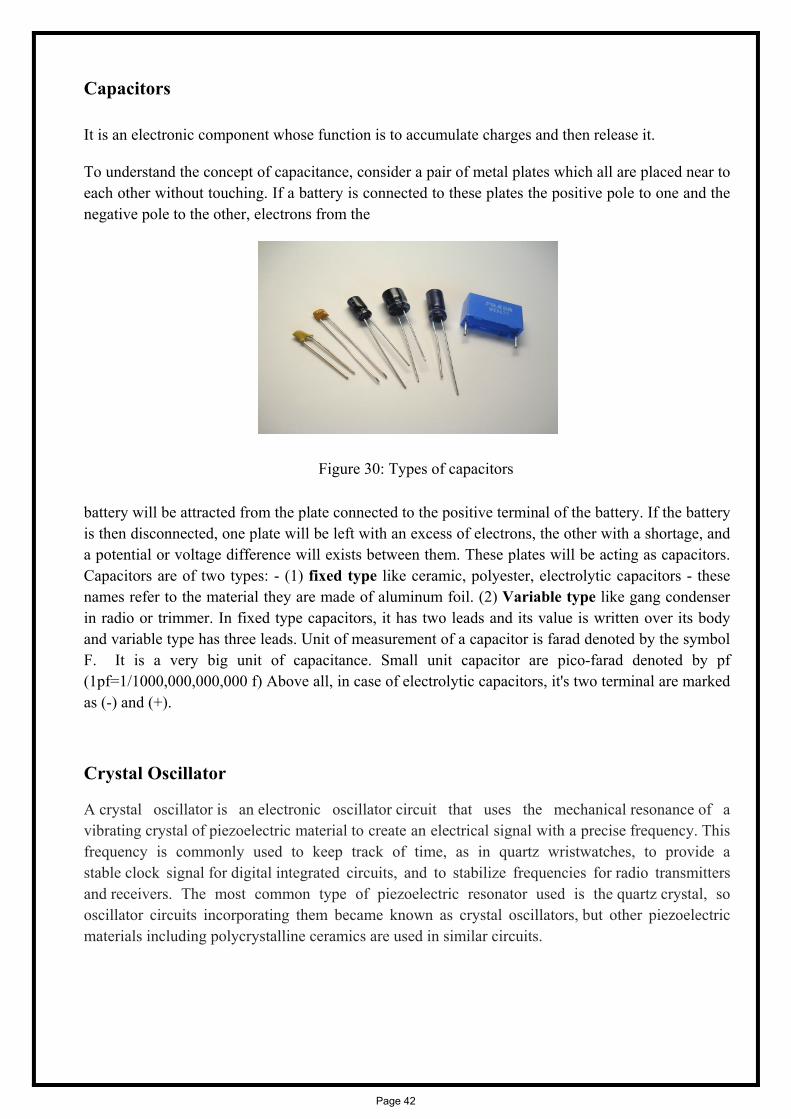
Capacitors
It is an electronic component whose function is to accumulate charges and then release it.
To understand the concept of capacitance, consider a pair of metal plates which all are placed near to each other without touching. If a battery is connected to these plates the positive pole to one and the negative pole to the other, electrons from the
Figure 30: Types of capacitors
battery will be attracted from the plate connected to the positive terminal of the battery. If the battery is then disconnected, one plate will be left with an excess of electrons, the other with a shortage, and a potential or voltage difference will exists between them. These plates will be acting as capacitors. Capacitors are of two types: - (1) fixed type like ceramic, polyester, electrolytic capacitors - these names refer to the material they are made of aluminum foil. (2) Variable type like gang condenser in radio or trimmer. In fixed type capacitors, it has two leads and its value is written over its body and variable type has three leads. Unit of measurement of a capacitor is farad denoted by the symbol F. It is a very big unit of capacitance. Small unit capacitor are pico-farad denoted by pf (1pf=1/1000,000,000,000 f) Above all, in case of electrolytic capacitors, it's two terminal are marked as (-) and (+).
Crystal Oscillator
A crystal oscillator is an electronic oscillator circuit that uses the mechanical resonance of a vibrating crystal of piezoelectric material to create an electrical signal with a precise frequency. This frequency is commonly used to keep track of time, as in quartz wristwatches, to provide a stable clock signal for digital integrated circuits, and to stabilize frequencies for radio transmitters and receivers. The most common type of piezoelectric resonator used is the quartz crystal, so oscillator circuits incorporating them became known as crystal oscillators, but other piezoelectric materials including polycrystalline ceramics are used in similar circuits.
Page 42

Figure 31: Crystal Oscillator
Quartz crystals are manufactured for frequencies from a few tens of kilohertz to hundreds of megahertz. More than two billion crystals are manufactured annually. Most are used for consumer devices such as wristwatches, clocks, radios, computers, and cell phones. Quartz crystals are also found inside test and measurement equipment, such as counters, signal generators, and oscilloscopes.
Piezo buzzer
A buzzer or beeper is an audio signaling device, which may be mechanical, electromechanical, or piezoelectric. Typical uses of buzzers and beepers include alarm devices, timers and confirmation of user input such as a mouse click or keystroke. A piezoelectric element may be driven by an oscillating electronic circuit or other audio signal source, driven with a piezoelectric audio amplifier. Sounds commonly used to indicate that a button has been pressed are a click, a ring or a beep.
Figure 32: Piezo Buzzer
Blank PCB
A printed circuit board (PCB) mechanically supports and electrically connects electronic components using conductive tracks, pads and other features etched from copper sheets laminated onto a non-conductive substrate. PCBs can be single sided (one copper layer), double sided (two copper layers) or multi-layer (outer and inner layers). Multi-layer PCBs allow for much higher component density. Conductors on different layers are connected with plated-through holes called vias. Advanced PCBs may contain components - capacitors, resistors or active devices - embedded in the substrate.
Page 43

Figure 33: Blank glass epoxy PCB Board
FR-4 glass epoxy is the primary insulating substrate upon which the vast majority of rigid PCBs are produced. A thin layer of copper foil is laminated to one or both sides of an FR-4 panel. Circuitry interconnections are etched into copper layers to produce printed circuit boards. Complex circuits are produced in multiple layers.
Printed circuit boards are used in all but the simplest electronic products. Alternatives to PCBs include wire wrap and point-to-point construction. PCBs require the additional design effort to lay out the circuit, but manufacturing and assembly can be automated. Manufacturing circuits with PCBs is cheaper and faster than with other wiring methods as components are mounted and wired with one single part. Furthermore, operator wiring errors are eliminated.
Page 44

Appendix B (Software coding)
Page 45
PROGRAM CODE:
//including Library #include <ESP8266WiFi.h> #include <PubSubClient.h> #include <aREST.h> // Clients WiFiClient espClient; PubSubClient client(espClient); // Create aREST instance aREST rest = aREST(client); // aREST Pro key (that you can get at dashboard.arest.io) char * key = "lbwu06are9gdn7wc"; // WiFi parameters const char* ssid = "Budhaditya"; const char* password = "buddy1234"; // Variables to be exposed to the API int temperature; int humidity; // Functions void callback(char* topic, byte* payload, unsigned int length); void setup(void) // Start Serial Serial.begin(115200); // Set aREST key rest.setKey(key, client); // Set callback client.setCallback(callback); // Give name to device rest.set_name("esp_relay"); // Connect to WiFi WiFi.begin(ssid, password); while (WiFi.status() != WL_CONNECTED)
Page 46

delay(500); Serial.print("."); Serial.println(""); Serial.println("WiFi connected"); // Set output topic char* out_topic = rest.get_topic(); void loop() // Connect to the cloud rest.handle(client); // Handles message arrived on subscribed topic(s) void callback(char* topic, byte* payload, unsigned int length) rest.handle_callback(client, topic, payload, length);
Page 47
Appendix C (Data sheets)
Page 48
1 www.handsontec.com
Handson Technology
User Manual V1.2
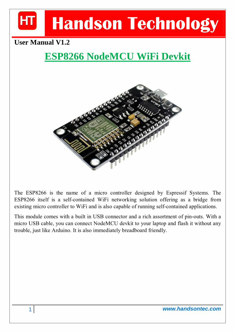
The ESP8266 is the name of a micro controller designed by Espressif Systems. The ESP8266 itself is a self-contained WiFi networking solution offering as a bridge from existing micro controller to WiFi and is also capable of running self-contained applications.
This module comes with a built in USB connector and a rich assortment of pin-outs. With a micro USB cable, you can connect NodeMCU devkit to your laptop and flash it without any trouble, just like Arduino. It is also immediately breadboard friendly.
ESP8266 NodeMCU WiFi Devkit

2 www.handsontec.com
Table of Contents 1. Specification:....................................................................................................................................................... 3
2. Pin Definition: ..................................................................................................................................................... 3
3. Using Arduino IDE ............................................................................................................................................... 3
3.1 Install the Arduino IDE 1.6.4 or greater ........................................................................................................ 4
3.2 Install the ESP8266 Board Package............................................................................................................... 4
3.3 Setup ESP8266 Support ............................................................................................................................... 5
3.4 Blink Test ..................................................................................................................................................... 7
3.5 Connecting via WiFi ..................................................................................................................................... 9
4. Flashing NodeMCU Firmware on the ESP8266 using Windows........................................................................... 12
4.1 Parts Required: ................................................................................................................................................ 12
4.2 Pin Assignment: ............................................................................................................................................... 12
4.3 Wiring: ............................................................................................................................................................ 13
4.4 Downloading NodeMCU Flasher for Windows ................................................................................................. 13
4.5 Flashing your ESP8266 using Windows ............................................................................................................ 13
5. Getting Started with the ESPlorer IDE ................................................................................................................ 15
5.1 Installing ESPlorer ............................................................................................................................................ 15
5.2 Schematics ...................................................................................................................................................... 18
5.3 Writing Your Lua Script .................................................................................................................................... 18
6. NodeMCU GPIO for Lua ......................................................................................................................................... 22
7. Web Resources: .................................................................................................................................................... 22
3 www.handsontec.com
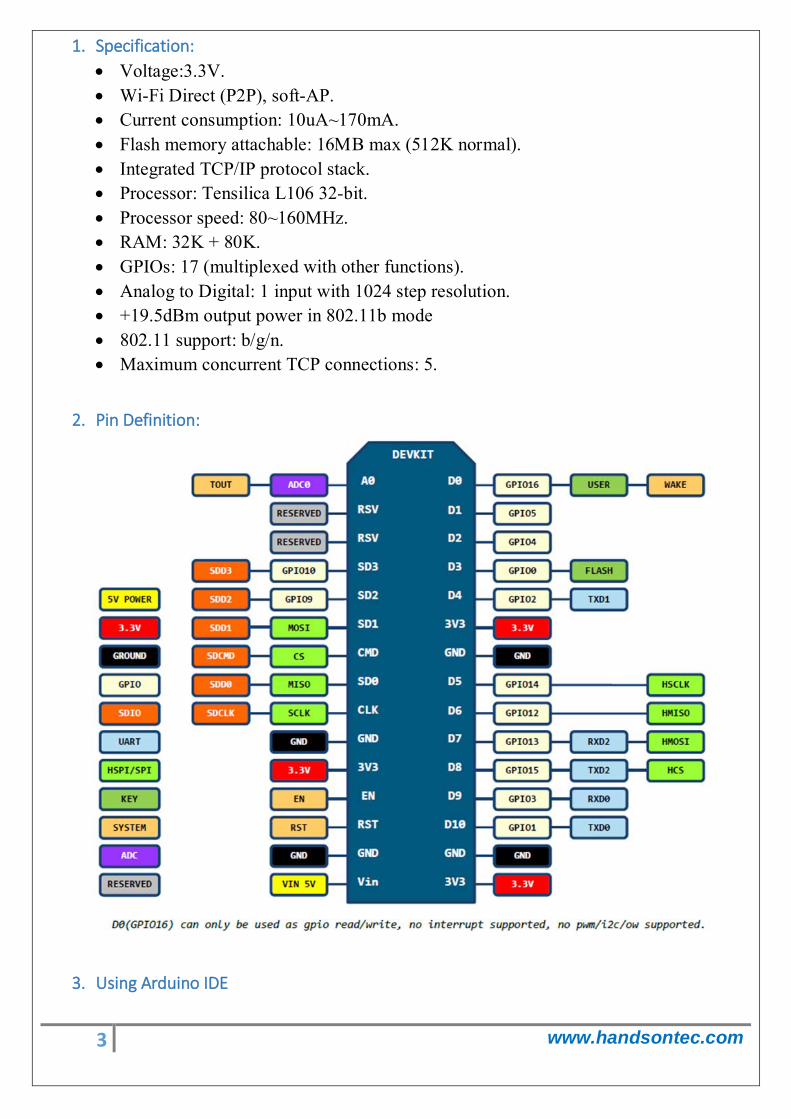
1. Specification: • Voltage:3.3V. • Wi-Fi Direct (P2P), soft-AP. • Current consumption: 10uA~170mA. • Flash memory attachable: 16MB max (512K normal). • Integrated TCP/IP protocol stack. • Processor: Tensilica L106 32-bit. • Processor speed: 80~160MHz. • RAM: 32K + 80K. • GPIOs: 17 (multiplexed with other functions). • Analog to Digital: 1 input with 1024 step resolution. • +19.5dBm output power in 802.11b mode • 802.11 support: b/g/n. • Maximum concurrent TCP connections: 5.
2. Pin Definition:
3. Using Arduino IDE

4 www.handsontec.com
The most basic way to use the ESP8266 module is to use serial commands, as the chip is basically a WiFi/Serial transceiver. However, this is not convenient. What we recommend is using the very cool Arduino ESP8266 project, which is a modified version of the Arduino IDE that you need to install on your computer. This makes it very convenient to use the ESP8266 chip as we will be using the well-known Arduino IDE. Following the below step to install ESP8266 library to work in Arduino IDE environment.
3.1 Install the Arduino IDE 1.6.4 or greater Download Arduino IDE from Arduino.cc (1.6.4 or greater) - don't use 1.6.2 or lower version! You can use your existing IDE if you have already installed it.
You can also try downloading the ready-to-go package from the ESP8266-Arduino project, if the proxy is giving you problems.
3.2 Install the ESP8266 Board Package Enter http://arduino.esp8266.com/stable/package_esp8266com_index.json into Additional Board Manager URLs field in the Arduino v1.6.4+ preferences.
Click ‘File’ -> ‘Preferences’ to access this panel.
Next, use the Board manager to install the ESP8266 package.

5 www.handsontec.com
Click ‘Tools’ -> ‘Board:’ -> ‘Board Manager…’ to access this panel.
Scroll down to ‘ esp8266 by ESP8266 Community ’ and click “Install” button to install the ESP8266 library package. Once installation completed, close and re-open Arduino IDE for ESP8266 library to take effect.
3.3 Setup ESP8266 Support When you've restarted Arduino IDE, select ‘Generic ESP8266 Module’ from the ‘Tools’ -> ‘Board:’ dropdown menu.
Select 80 MHz as the CPU frequency (you can try 160 MHz overclock later)

6 www.handsontec.com
Select ‘115200’ baud upload speed is a good place to start - later on you can try higher speeds but 115200 is a good safe place to start.
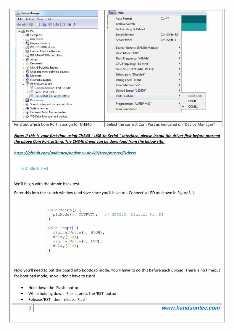
Go to your Windows ‘Device Manager’ to find out which Com Port ‘USB-Serial CH340’ is assigned to. Select the matching COM/serial port for your CH340 USB-Serial interface.
7 www.handsontec.com
Find out which Com Port is assign for CH340 Select the correct Com Port as indicated on ‘Device Manager” Note: if this is your first time using CH340 “ USB-to-Serial ” interface, please install the driver first before proceed the above Com Port setting. The CH340 driver can be download from the below site:
3.4 Blink Test
https://github.com/nodemcu/nodemcu-devkit/tree/master/Drivers
We'll begin with the simple blink test.
Enter this into the sketch window (and save since you'll have to). Connect a LED as shown in Figure3-1.
void setup() pinMode(5, OUTPUT); // GPIO05, Digital Pin D1 void loop() digitalWrite(5, HIGH); delay(900); digitalWrite(5, LOW); delay(500);
Now you'll need to put the board into bootload mode. You'll have to do this before each upload. There is no timeout for bootload mode, so you don't have to rush!
• Hold down the ‘Flash’ button. • While holding down ‘ Flash’, press the ‘RST’ button. • Release ‘RST’, then release ‘Flash’

8 www.handsontec.com
• When you release the ‘RST’ button, the blue indication will blink once, this means its ready to bootload.
Once the ESP board is in bootload mode, upload the sketch via the IDE, Figure 3-2.
Figure3-1: Connection diagram for the blinking test

9 www.handsontec.com
Figure 3.2: Uploading the sketch to ESP8266 NodeMCU module.
The sketch will start immediately - you'll see the LED blinking. Hooray!
3.5 Connecting via WiFi
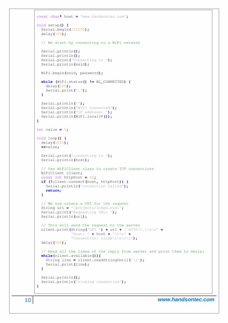
OK once you've got the LED blinking, let’s go straight to the fun part, connecting to a webserver. Create a new sketch with this code:
Don’t forget to update:
const char* ssid = "yourssid";
const char* password = "yourpassword";
to your WiFi access point and password, then upload the same way: get into bootload mode, then upload code via IDE.
/* * Simple HTTP get webclient test */
#include <ESP8266WiFi.h> const char* ssid = "handson"; // key in your own SSID const char* password = "abc1234"; // key in your own WiFi access point password
10 www.handsontec.com
const char* host = "www.handsontec.com"; void setup() Serial.begin(115200); delay(100); // We start by connecting to a WiFi network Serial.println(); Serial.println(); Serial.print("Connecting to "); Serial.println(ssid); WiFi.begin(ssid, password); while (WiFi.status() != WL_CONNECTED) delay(500); Serial.print("."); Serial.println(""); Serial.println("WiFi connected"); Serial.println("IP address: "); Serial.println(WiFi.localIP()); int value = 0; void loop() delay(5000); ++value; Serial.print("connecting to "); Serial.println(host); // Use WiFiClient class to create TCP connections WiFiClient client; const int httpPort = 80; if (!client.connect(host, httpPort)) Serial.println("connection failed"); return; // We now create a URI for the request String url = "/projects/index.html"; Serial.print("Requesting URL: "); Serial.println(url); // This will send the request to the server client.print(String("GET ") + url + " HTTP/1.1\r\n" + "Host: " + host + "\r\n" + "Connection: close\r\n\r\n"); delay(500); // Read all the lines of the reply from server and print them to Serial while(client.available()) String line = client.readStringUntil('\r'); Serial.print(line); Serial.println(); Serial.println("closing connection");
11 www.handsontec.com
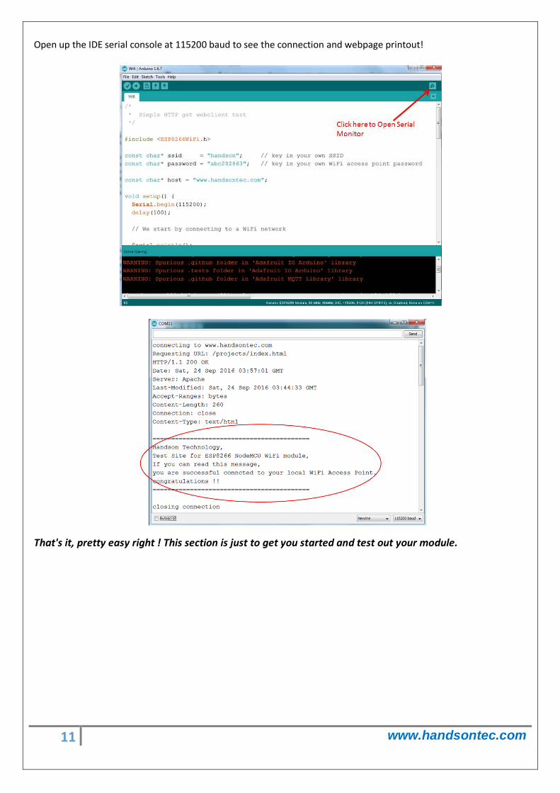
Open up the IDE serial console at 115200 baud to see the connection and webpage printout!
That's it, pretty easy right ! This section is just to get you started and test out your module.

7C
6C
5C
4C
3C
2C
1C
COM
7
6
5
4
3
2
1
7B
6B
5B
4B
3B
2B
1B
10
11
12
13
14
15
16
9
Product
Folder
Sample &Buy
Technical
Documents
Tools &
Software
Support &Community
An IMPORTANT NOTICE at the end of this data sheet addresses availability, warranty, changes, use in safety-critical applications,intellectual property matters and other important disclaimers. PRODUCTION DATA.
ULN2002A, ULN2003A, ULN2003AIULQ2003A, ULN2004A, ULQ2004A
SLRS027O –DECEMBER 1976–REVISED JANUARY 2016
ULN200x, ULQ200x High-Voltage, High-Current Darlington Transistor Arrays
1
1 Features1• 500-mA-Rated Collector Current (Single Output)• High-Voltage Outputs: 50 V• Output Clamp Diodes• Inputs Compatible With Various Types of Logic• Relay-Driver Applications
2 Applications• Relay Drivers• Stepper and DC Brushed Motor Drivers• Lamp Drivers• Display Drivers (LED and Gas Discharge)• Line Drivers• Logic Buffers
3 DescriptionThe ULx200xA devices are high-voltage, high-currentDarlington transistor arrays. Each consists of sevenNPN Darlington pairs that feature high-voltageoutputs with common-cathode clamp diodes forswitching inductive loads.
The collector-current rating of a single Darlington pairis 500 mA. The Darlington pairs can be paralleled forhigher current capability. Applications include relaydrivers, hammer drivers, lamp drivers, display drivers(LED and gas discharge), line drivers, and logicbuffers. For 100-V (otherwise interchangeable)versions of the ULx2003A devices, see the SLRS023data sheet for the SN75468 and SN75469 devices.
The ULN2002A device is designed specifically for usewith 14-V to 25-V PMOS devices. Each input of thisdevice has a Zener diode and resistor in series tocontrol the input current to a safe limit. TheULx2003A devices have a 2.7-kΩ series base resistorfor each Darlington pair for operation directly withTTL or 5-V CMOS devices.
The ULx2004A devices have a 10.5-kΩ series baseresistor to allow operation directly from CMOSdevices that use supply voltages of 6 V to 15 V. Therequired input current of the ULx2004A device isbelow that of the ULx2003A devices, and the requiredvoltage is less than that required by the ULN2002Adevice.
.
Device Information(1)
PART NUMBER PACKAGE BODY SIZE (NOM)ULx200xD SOIC (16) 9.90 mm × 3.91 mmULx200xN PDIP (16) 19.30 mm × 6.35 mmULN200xNS SOP (16) 10.30 mm × 5.30 mmULN200xPW TSSOP (16) 5.00 mm × 4.40 mm
(1) For all available packages, see the orderable addendum atthe end of the data sheet.
.
.
Simplified Block Diagram

2
ULN2002A, ULN2003A, ULN2003AIULQ2003A, ULN2004A, ULQ2004ASLRS027O –DECEMBER 1976–REVISED JANUARY 2016 www.ti.com
Product Folder Links: ULN2002A ULN2003A ULN2003AI ULQ2003A ULN2004A ULQ2004A
Submit Documentation Feedback Copyright © 1976–2016, Texas Instruments Incorporated
Table of Contents1 Features .................................................................. 12 Applications ........................................................... 13 Description ............................................................. 14 Revision History..................................................... 25 Pin Configuration and Functions ......................... 36 Specifications......................................................... 4
6.1 Absolute Maximum Ratings ...................................... 46.2 ESD Ratings.............................................................. 46.3 Recommended Operating Conditions....................... 46.4 Thermal Information .................................................. 46.5 Electrical Characteristics: ULN2002A ....................... 56.6 Electrical Characteristics: ULN2003A and
ULN2004A.................................................................. 56.7 Electrical Characteristics: ULN2003AI ...................... 66.8 Electrical Characteristics: ULN2003AI ..................... 66.9 Electrical Characteristics: ULQ2003A and
ULQ2004A ................................................................. 76.10 Switching Characteristics: ULN2002A, ULN2003A,
ULN2004A.................................................................. 76.11 Switching Characteristics: ULN2003AI .................. 76.12 Switching Characteristics: ULN2003AI .................. 86.13 Switching Characteristics: ULQ2003A, ULQ2004A 86.14 Typical Characteristics ............................................ 8
7 Parameter Measurement Information ................ 108 Detailed Description ............................................ 12
8.1 Overview ................................................................. 128.2 Functional Block Diagrams ..................................... 128.3 Feature Description................................................. 138.4 Device Functional Modes........................................ 13
9 Application and Implementation ........................ 149.1 Application Information............................................ 149.2 Typical Application ................................................. 149.3 System Examples ................................................... 17
10 Power Supply Recommendations ..................... 1811 Layout................................................................... 18
11.1 Layout Guidelines ................................................. 1811.2 Layout Example .................................................... 18
12 Device and Documentation Support ................. 1912.1 Documentation Support ........................................ 1912.2 Related Links ........................................................ 1912.3 Community Resources.......................................... 1912.4 Trademarks ........................................................... 1912.5 Electrostatic Discharge Caution............................ 1912.6 Glossary ................................................................ 19
13 Mechanical, Packaging, and OrderableInformation ........................................................... 19
4 Revision HistoryNOTE: Page numbers for previous revisions may differ from page numbers in the current version.
Changes from Revision N (June 2015) to Revision O Page
• Changed Pin Functions table to correct typographical error. ................................................................................................ 3
Changes from Revision M (February 2013) to Revision N Page
• Added Pin Configuration and Functions section, ESD Ratings table, Feature Description section, Device FunctionalModes, Application and Implementation section, Power Supply Recommendations section, Layout section, Deviceand Documentation Support section, and Mechanical, Packaging, and Orderable Information section .............................. 1
• Deleted Ordering Information table. No specification changes. ............................................................................................. 1• Moved Typical Characteristics into Specifications section. ................................................................................................... 8
Changes from Revision L (April 2012) to Revision M Page
• Updated temperature rating for ULN2003AI in the ORDERING INFORMATION table ........................................................ 1
Changes from Revision K (August 2011) to Revision L Page
• Removed reference to obsolete ULN2001 device.................................................................................................................. 1

1B 1 16
2B 2 15
3B 3 14
4B 4 13
5B 5 12
6B 6 11
7B 7 10
E 8 9
1C
2C
3C
4C
5C
6C
7C
COM
3
ULN2002A, ULN2003A, ULN2003AIULQ2003A, ULN2004A, ULQ2004A
www.ti.com SLRS027O –DECEMBER 1976–REVISED JANUARY 2016
Product Folder Links: ULN2002A ULN2003A ULN2003AI ULQ2003A ULN2004A ULQ2004A
Submit Documentation FeedbackCopyright © 1976–2016, Texas Instruments Incorporated
(1) I = Input, O = Output
5 Pin Configuration and Functions
D, N, NS, and PW Package16-Pin SOIC, PDIP, SO, and TSSOP
Top View
Pin FunctionsPIN
I/O (1) DESCRIPTIONNAME NO.1B 1
I Channel 1 through 7 Darlington base input
2B 23B 34B 45B 56B 67B 71C 16
O Channel 1 through 7 Darlington collector output
2C 153C 144C 135C 126C 117C 10COM 9 — Common cathode node for flyback diodes (required for inductive loads)E 8 — Common emitter shared by all channels (typically tied to ground)
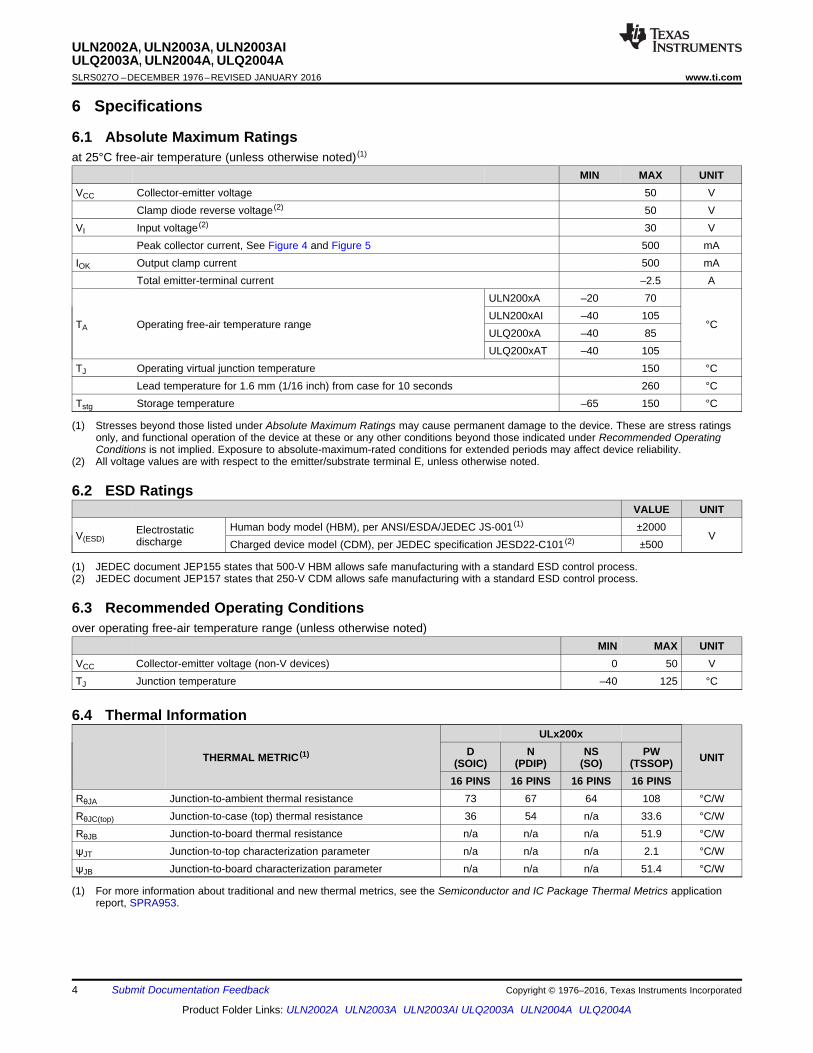
4
ULN2002A, ULN2003A, ULN2003AIULQ2003A, ULN2004A, ULQ2004ASLRS027O –DECEMBER 1976–REVISED JANUARY 2016 www.ti.com
Product Folder Links: ULN2002A ULN2003A ULN2003AI ULQ2003A ULN2004A ULQ2004A
Submit Documentation Feedback Copyright © 1976–2016, Texas Instruments Incorporated
(1) Stresses beyond those listed under Absolute Maximum Ratings may cause permanent damage to the device. These are stress ratingsonly, and functional operation of the device at these or any other conditions beyond those indicated under Recommended OperatingConditions is not implied. Exposure to absolute-maximum-rated conditions for extended periods may affect device reliability.
(2) All voltage values are with respect to the emitter/substrate terminal E, unless otherwise noted.
6 Specifications
6.1 Absolute Maximum Ratingsat 25°C free-air temperature (unless otherwise noted) (1)
MIN MAX UNITVCC Collector-emitter voltage 50 V
Clamp diode reverse voltage (2) 50 VVI Input voltage (2) 30 V
Peak collector current, See Figure 4 and Figure 5 500 mAIOK Output clamp current 500 mA
Total emitter-terminal current –2.5 A
TA Operating free-air temperature range
ULN200xA –20 70
°CULN200xAI –40 105ULQ200xA –40 85ULQ200xAT –40 105
TJ Operating virtual junction temperature 150 °CLead temperature for 1.6 mm (1/16 inch) from case for 10 seconds 260 °C
Tstg Storage temperature –65 150 °C
(1) JEDEC document JEP155 states that 500-V HBM allows safe manufacturing with a standard ESD control process.(2) JEDEC document JEP157 states that 250-V CDM allows safe manufacturing with a standard ESD control process.
6.2 ESD RatingsVALUE UNIT
V(ESD)Electrostaticdischarge
Human body model (HBM), per ANSI/ESDA/JEDEC JS-001 (1) ±2000V
Charged device model (CDM), per JEDEC specification JESD22-C101 (2) ±500
6.3 Recommended Operating Conditionsover operating free-air temperature range (unless otherwise noted)
MIN MAX UNITVCC Collector-emitter voltage (non-V devices) 0 50 VTJ Junction temperature –40 125 °C
(1) For more information about traditional and new thermal metrics, see the Semiconductor and IC Package Thermal Metrics applicationreport, SPRA953.
6.4 Thermal Information
THERMAL METRIC (1)
ULx200x
UNITD(SOIC)
N(PDIP)
NS(SO)
PW(TSSOP)
16 PINS 16 PINS 16 PINS 16 PINSRθJA Junction-to-ambient thermal resistance 73 67 64 108 °C/WRθJC(top) Junction-to-case (top) thermal resistance 36 54 n/a 33.6 °C/WRθJB Junction-to-board thermal resistance n/a n/a n/a 51.9 °C/WψJT Junction-to-top characterization parameter n/a n/a n/a 2.1 °C/WψJB Junction-to-board characterization parameter n/a n/a n/a 51.4 °C/W

5
ULN2002A, ULN2003A, ULN2003AIULQ2003A, ULN2004A, ULQ2004A
www.ti.com SLRS027O –DECEMBER 1976–REVISED JANUARY 2016
Product Folder Links: ULN2002A ULN2003A ULN2003AI ULQ2003A ULN2004A ULQ2004A
Submit Documentation FeedbackCopyright © 1976–2016, Texas Instruments Incorporated
6.5 Electrical Characteristics: ULN2002ATA = 25°C
PARAMETER TEST FIGURE TEST CONDITIONSULN2002A
UNITMIN TYP MAX
VI(on) ON-state input voltage Figure 14 VCE = 2 V, IC = 300 mA 13 V
VOHHigh-level output voltage afterswitching Figure 18 VS = 50 V, IO = 300 mA VS – 20 mV
VCE(sat)Collector-emitter saturationvoltage Figure 12
II = 250 μA, IC = 100 mA 0.9 1.1VII = 350 μA, IC = 200 mA 1 1.3
II = 500 μA, IC = 350 mA 1.2 1.6VF Clamp forward voltage Figure 15 IF = 350 mA 1.7 2 V
ICEX Collector cutoff currentFigure 9 VCE = 50 V, II = 0 50
μAFigure 10 VCE = 50 V,
TA = 70°CII = 0 100VI = 6 V 500
II(off) OFF-state input current Figure 10 VCE = 50 V, IC = 500 μA 50 65 μAII Input current Figure 11 VI = 17 V 0.82 1.25 mA
IR Clamp reverse current Figure 14VR = 50 V TA = 70°C 100
μAVR = 50 V 50
Ci Input capacitance VI = 0, f = 1 MHz 25 pF
6.6 Electrical Characteristics: ULN2003A and ULN2004ATA = 25°C
PARAMETER TESTFIGURE TEST CONDITIONS
ULN2003A ULN2004AUNIT
MIN TYP MAX MIN TYP MAX
VI(on)ON-state inputvoltage Figure 14 VCE = 2 V
IC = 125 mA 5
V
IC = 200 mA 2.4 6IC = 250 mA 2.7IC = 275 mA 7IC = 300 mA 3IC = 350 mA 8
VOH
High-level outputvoltage afterswitching
Figure 18 VS = 50 V, IO = 300 mA VS – 20 VS – 20 mV
VCE(sat)Collector-emittersaturation voltage Figure 13
II = 250 μA, IC = 100 mA 0.9 1.1 0.9 1.1VII = 350 μA, IC = 200 mA 1 1.3 1 1.3
II = 500 μA, IC = 350 mA 1.2 1.6 1.2 1.6
ICEXCollector cutoffcurrent
Figure 9 VCE = 50 V, II = 0 50 50μA
Figure 10 VCE = 50 V,TA = 70°C
II = 0 100 100VI = 6 V 500
VFClamp forwardvoltage Figure 16 IF = 350 mA 1.7 2 1.7 2 V
II(off)Off-state inputcurrent Figure 11 VCE = 50 V,
TA = 70°C, IC = 500 μA 50 65 50 65 μA
II Input current Figure 12VI = 3.85 V 0.93 1.35
mAVI = 5 V 0.35 0.5VI = 12 V 1 1.45
IRClamp reversecurrent Figure 15
VR = 50 V 50 50μA
VR = 50 V TA = 70°C 100 100Ci Input capacitance VI = 0, f = 1 MHz 15 25 15 25 pF
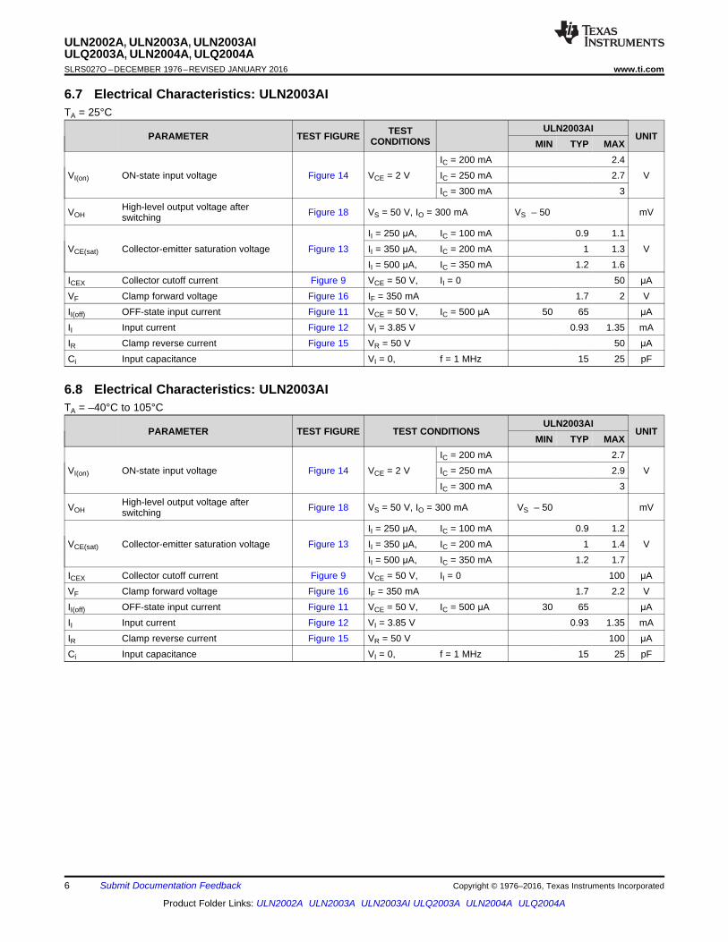
6
ULN2002A, ULN2003A, ULN2003AIULQ2003A, ULN2004A, ULQ2004ASLRS027O –DECEMBER 1976–REVISED JANUARY 2016 www.ti.com
Product Folder Links: ULN2002A ULN2003A ULN2003AI ULQ2003A ULN2004A ULQ2004A
Submit Documentation Feedback Copyright © 1976–2016, Texas Instruments Incorporated
6.7 Electrical Characteristics: ULN2003AITA = 25°C
PARAMETER TEST FIGURE TESTCONDITIONS
ULN2003AIUNIT
MIN TYP MAX
VI(on) ON-state input voltage Figure 14 VCE = 2 VIC = 200 mA 2.4
VIC = 250 mA 2.7IC = 300 mA 3
VOHHigh-level output voltage afterswitching Figure 18 VS = 50 V, IO = 300 mA VS – 50 mV
VCE(sat) Collector-emitter saturation voltage Figure 13II = 250 μA, IC = 100 mA 0.9 1.1
VII = 350 μA, IC = 200 mA 1 1.3II = 500 μA, IC = 350 mA 1.2 1.6
ICEX Collector cutoff current Figure 9 VCE = 50 V, II = 0 50 μAVF Clamp forward voltage Figure 16 IF = 350 mA 1.7 2 VII(off) OFF-state input current Figure 11 VCE = 50 V, IC = 500 μA 50 65 μAII Input current Figure 12 VI = 3.85 V 0.93 1.35 mAIR Clamp reverse current Figure 15 VR = 50 V 50 μACi Input capacitance VI = 0, f = 1 MHz 15 25 pF
6.8 Electrical Characteristics: ULN2003AITA = –40°C to 105°C
PARAMETER TEST FIGURE TEST CONDITIONSULN2003AI
UNITMIN TYP MAX
VI(on) ON-state input voltage Figure 14 VCE = 2 VIC = 200 mA 2.7
VIC = 250 mA 2.9IC = 300 mA 3
VOHHigh-level output voltage afterswitching Figure 18 VS = 50 V, IO = 300 mA VS – 50 mV
VCE(sat) Collector-emitter saturation voltage Figure 13II = 250 μA, IC = 100 mA 0.9 1.2
VII = 350 μA, IC = 200 mA 1 1.4II = 500 μA, IC = 350 mA 1.2 1.7
ICEX Collector cutoff current Figure 9 VCE = 50 V, II = 0 100 μAVF Clamp forward voltage Figure 16 IF = 350 mA 1.7 2.2 VII(off) OFF-state input current Figure 11 VCE = 50 V, IC = 500 μA 30 65 μAII Input current Figure 12 VI = 3.85 V 0.93 1.35 mAIR Clamp reverse current Figure 15 VR = 50 V 100 μACi Input capacitance VI = 0, f = 1 MHz 15 25 pF