global supplier quality manual revision 6 defense addendum.… · found on the website. 8. surface...
TRANSCRIPT

DEFENSE SEGMENT ADDENDUM
All rights reserved under the copyright laws. Printed copies of this document are uncontrolled. 1
Global Supplier Quality Manual
DEFENSE SEGMENT ADDENDUM
Revision 1.2 November 15, 2017

DEFENSE SEGMENT ADDENDUM
All rights reserved under the copyright laws. Printed copies of this document are uncontrolled. 2
Table of Contents 1. Defense Segment Quality Assurance Requirements Introduction .............................. 3 2. Record and Documentation Retention Requirements ................................................ 3 3. Certificate of Conformance ......................................................................................... 3 4. Counterfeit/Used Parts ............................................................................................... 3 5. Ball Studs and Ball Socket Assemblies ...................................................................... 4 6. Source Inspection....................................................................................................... 5 7. Packaging and Shipping ............................................................................................. 5 8. Surface Preparation, Painting and Finishing .............................................................. 5 9. Part Marking / Identification and Traceability ............................................................... 6 10. Casting Radiography Introduction ............................................................................ 7 11. Welding Procedure Introduction ............................................................................... 8 12. Component First Article Testing (CFAT) ................................................................ 10 13. PPAP Requirements Overview............................................................................... 12 14. Revision Control Table ........................................................................................... 26
DEFENSE SEGMENT ADDENDUM
All rights reserved under the copyright laws. Printed copies of this document are uncontrolled. 3
1. Defense Segment Quality Assurance Requirements Introduction Suppliers shall have a quality assurance program that is compliant to ISO 9001-2015, as a minimum. Suppliers to the JLTV contract (#W56HZV15C0095) shall have a quality assurance program that is certified to ISO 9001:2015 or ISO/IATF16949 registered by an accredited third party registrar. In addition, all suppliers shall have a quality management system that meets the requirements of the Oshkosh GSQM. Suppliers are subject to audit by Oshkosh Corporation to assure that a documented quality system is in place which includes development, implementation, and maintenance of Control Plans for all Defense programs and products. 2. Record and Documentation Retention Requirements While in storage, records and documents shall be protected from damage, loss and deterioration due to environmental conditions. Records shall be maintained for (5) years. At the end of (5) years, the Supplier shall provide Oshkosh Defense with the option of having the records forwarded to Oshkosh Defense for further retention, as required by the contract, or authorizing disposal of the records and documents at the Supplier’s location. Disposition shall be done in a timely and appropriate manner. Oshkosh Defense shall be notified when disposition has taken place. 3. Certificate of Conformance The Supplier shall establish, implement and maintain documented procedures, which ensure adherence to the Oshkosh Defense Certificate of Conformance requirement. The supplier shall have an authorized representative certify that the parts ordered have been processed to procedures that ensure the material is conforming and free of counterfeit material. The certificate of conformance will also acknowledge proper adherence to Purchase Orders, drawings, and contract requirements. Suppliers shall utilize the Oshkosh Certificate of Conformance form (QC-0899) located on http://osn.oshkoshcorp.com/ or another Certificate of Conformance form that at minimum contains all the information required per the Oshkosh Certificate of Conformance form. The supplier shall complete and retain a Certificate of Conformance for each shipment of material. This record shall be retained at the supplier’s location for 5 years. This document must be made available at the request of Oshkosh within 24 hours. 4. Counterfeit/Used Parts The Defense Supplier shall establish, implement and maintain documented procedures, which shall preclude and/or detect the use of counterfeit/used parts. All Suppliers providing “electronic parts” (as defined within DFARS 252.246.7007, a) shall have developed and documented Purchasing procedures that reduce the risk of purchasing and utilizing counterfeit material. Suppliers shall have defined and documented Product Verification procedures that assure the detection of counterfeit parts prior to formal product acceptance. Suppliers shall have developed and documented a Material Control Procedure that includes quarantining, reporting, and dispositioning suspect and/or counterfeit components. Reference the Supplier Standard Guide,

DEFENSE SEGMENT ADDENDUM
All rights reserved under the copyright laws. Printed copies of this document are uncontrolled. 4
Section F, Attachment 2, Contractor Counterfeit Electronic Parts Detection and Avoidance for compliance requirements. https://osn.oshkoshcorp.com/docs/ssg/SECT_F_Attach_2.pdf 5. Ball Studs and Ball Socket Assemblies Defense suppliers of these components and/or assemblies shall demonstrate product and feature conformance as referenced within SAE J491 and outlined below.
5.1 Definitions • Master Gage: a taper gage that serves as a standard or base, designed to specific
dimensions within blueprint specifications • Bluing Paste: a non-drying light paste with a pigment or dye (such as “Prussian Blue”)
that colors a contacting surface • The level of contact must be 60% minimum area of contact when blued (see acceptable
patterns below) 5.2 Instructions for Testing
The following process must be followed when performing taper testing 1. The bore (female) and stud (male) features must be free of rough spots 2. Visually inspect the surfaces for dark spots or areas that are not cleaned-up 3. Check rocking motion of the stud or gage before applying blueing dye. The gage
should not rock when seated within the bore. 4. Apply bluing - must be distributed completely and evenly with a minimum
thickness on the taper surface of the master gage. 5. Warning - excessive bluing will skew the results 6. Insert gage by hand pressure and with a slight twisting motion (1/4 turn clockwise
and counter clockwise) 7. Ensure gage is firmly seated 8. Remove and inspect the bluing pattern 9. Conforming conditions usually exceed the minimum 60% contact, and result in
90% + of contact (use the diagrams shown in Image 5A below for guidance of acceptability)

DEFENSE SEGMENT ADDENDUM
All rights reserved under the copyright laws. Printed copies of this document are uncontrolled. 5
Image 5A - Taper Engagement Acceptability 6. Source Inspection During performance on this subcontract, the Supplier’s manufacturing and associated processes, products and inspection and/or test data are subject to review, verification, examination, test and/or analysis by authorized Government and/or Oshkosh representatives. 7. Packaging and Shipping The Supplier shall provide for adequate facilities and instructions for handling, packaging and shipping to preserve the products and prevent damage during storage and transit. See Section 23 from the Global Supplier Quality Manual for more detail. For specific requirements pertaining to Supplier Product Labeling, Packaging, and Shipping Instructions the Supplier shall adhere to Section J in the Supplier Standards Guide which can be found on the http://osn.oshkoshcorp.com/ website. 8. Surface Preparation, Painting and Finishing The Supplier must comply with the Oshkosh finish requirement specified on the print. When finish requirements are “silent”, suppliers shall reference the OSK PS-100 Paint Standard and/or FM100 Finish Methods. These documents can be found on the http://osn.oshkoshcorp.com/ website. Note: The purchase order may contain specific instructions regarding paint applications to facilitate subsequent operations. Note: Product shipping in “raw” (unfinished state) shall be pretreated with a corrosion preventative specified within the FM100. As referenced in Section D.32 of the Oshkosh Supplier Standards Guide, the use of any pretreatment, plating, painting, or coating of any kind that contains Hexavalent Chrome is strictly prohibited. Any supplier to Oshkosh Corporation shall have systems in place to monitor and control the coating processes used by upstream suppliers when plating requirements are not strictly defined within the Oshkosh design record. Hexavalent Chrome can appear in several forms, and can be known by many several nomenclatures. Regardless of the specific nomenclature referenced on the coating certification, usage is strictly prohibited. Different ways of representing Hexavalent chromium are given below:
• Hexavalent chromium • Hexavalent chrome • Hex chrome
Different plating specifications that may contain Hex Chrome (the specifications below may be prohibited. Due diligence is required to verify conformance).
• ASTM B633 (Standard for Electro deposited coatings of Zinc on Iron and Steel) • ASTM B633 (Coating thickness) Type II • ASTM B633 (Coating thickness) Type III

DEFENSE SEGMENT ADDENDUM
All rights reserved under the copyright laws. Printed copies of this document are uncontrolled. 6
• Zn/Fe SC (Coating thickness in micrometers) Type II • Zn/Fe SC (Coating thickness in micrometers) Type III • Zinc Yellow • Zinc Clear • Chromate • Chromate conversion coating • Zinc chromate • Zinc Dichromate
In addition, Dacromet is not specifically a chromate coating, but a type of Zinc-Rich paint which contains Hex chrome. 9. Part Marking / Identification and Traceability The OSK print provides guidance for part marking identification in accordance with Military Standard 130, but it does not specify the method or location in all cases.
9.1 Location Requirements Some drawings specify only compliance to Military Standard 130, and may/may not include the marking method or location on the part. In those instances, it is important to ensure the identification is visible and legible during normal operational use (if it is affixed to the part), and it needs to be permanent through the life cycle of the part. For components that are physically marked (by etching or stamping for example), the identification MUST be legible in its final state (after coating). It is the tier one supplier’s responsibility to ensure conformance to this requirement. For small components that cannot be marked physically, or tagged, select other alternatives within the standard. It is important that some method be used in part marking identification.
9.2 Lot Traceability / Serialization
It is recommended that the supplier utilize some method of traceability for each order fulfillment such as serialization or your company’s CAGE (IAW Military Standard 130). Traceability requirements are referenced on drawing #3912088, and available upon request. This becomes important if a recall is needed or when distinguishing product between suppliers.
9.3 Armor Armor traceability shall be maintained and linked to the UID label. Information to be tracked and linked shall include at a minimum: serial number, part number, heat number, lot number, material certification number, materials standard, and MIL CAGE code. For complex weldments or multi-piece assemblies, all material lots utilized for construction of that end item shall be recorded and linked to the UID label. The process of tracking the information prior to the final IUID label shall be in accordance with the prime contractor’s material traceability requirement. Traceability requirements are referenced on drawing #3912088, and available upon request.
DEFENSE SEGMENT ADDENDUM
All rights reserved under the copyright laws. Printed copies of this document are uncontrolled. 7
10. Castings Introduction
Castings shall be in accordance with CORP-PROC-ENG002, unless specified otherwise.
10.1 Radiographic Inspection Radiographic inspection reports shall be signed by a certified ASNT (American Society for Non-Destructive Testing) inspector, level II minimum. For the JLTV program (contract #W56HZV15C0095), radiographic reports shall be signed by a NAS 410 certified technician.
10.2 Inspection Frequency The first casting shall be radiographed in all routine and random positions described on the position chart (or in the supplier’s Control Plan if not detailed on the drawing).
Subsequent castings shall be radiographed in those areas that were defective in the immediately preceding castings, until compliance with the required standard has been obtained. Objective evidence shall be provided by the producer that corrective action has been taken to eliminate the deficiency.
10.2.1 Radiographic Inspection Process
1. PPAP submission: One part per mold cavity. PPAP submittals to include:
a. Radiographic inspection reports b. Radiographic images (with evidence that IQI’s were utilized) c. NAS 410 Certifications / ASNT Certifications d. Laboratory accreditations
2. Initial Production (first 10 lots): One part per mold cavity from every 30
molds poured. 3. Production Sampling: One part per mold cavity twice per year.
• Oshkosh reserves the right to conduct process audits to verify conformance to the above
requirement.
10.3 Rework / Repair All non-conforming areas may be repaired in accordance with an approved and qualified repair procedure (when required by applicable specification), and must meet the standard specified on applicable position chart. Suppliers shall utilize the F1000 (Supplier Change Request) form to initiate Oshkosh approval. The producer retains the prerogative of repairing or scrapping defective material. After above requirements have been accomplished, normal sampling shall be applied.
10.4 Radiography Position Requirements All routine and random positions shall be radiographed for initial production castings except when the total exceeds the established number of radiographs that can be taken in a normal eight hour day.

DEFENSE SEGMENT ADDENDUM
All rights reserved under the copyright laws. Printed copies of this document are uncontrolled. 8
When the total number of positions to be radiographed for initial production castings exceeds the maximum capability of facilities, random position shall be selected for radiography by an NAS 410 qualified operator, and rotated in such a manner that complete coverage is achieved within a cycle of five castings radiographed.
10.5 Occurrence Reaction The occurrence of a rejectable defect in any area on a casting shall require the radiographic inspection of each subsequently poured casting in that area until the defective condition is corrected. If the results of radiographic inspection on ten consecutive lots of material indicate a satisfactory uniform product meeting the soundness requirements is being produced, the amount of radiographic testing can be in accordance with Production Sampling outlined above. Objective records must demonstrate justification to advance from Initial Production sampling to Production Sampling.
11. Welding Procedure Introduction The Supplier shall develop and deliver Welding Procedure Specifications (WPS), Procedure Qualification Records (PQRs), and Weld Repair Procedures and in accordance with welding standard(s) The Supplier shall follow the appropriate welding standard(s) scope to qualify the welding and weld repair procedures. The Supplier shall prepare weld samples and test the weld procedure for qualification in accordance with the appropriate standard(s). Changes to the Weld Repair Procedures and WPS, or PQR that requires requalification, shall be resubmitted as part of a Supplier Change Request (F-1000). Welding Procedure Specifications (WPS), and Procedure Qualification Records (PQRs) The use of pre-qualified weld joints as specified in American Welding Society (AWS) D1.1 does not preclude submittal of welding procedures. All Welding documentation referenced above and in any subsequent section shall be made available to Oshkosh upon request.
11.1 Armor Welding Procedure Design Prior to manufacturing, the Supplier shall develop welding procedures for all ballistic weldments in accordance with the Ground Combat Vehicle Welding Code for Steel and the Ground Combat Vehicle Welding Code for Aluminum as applicable. All base materials used for ballistic weldments shall be qualified under the applicable MIL-DTL to be qualified as armor. 11.2 Structural Welding Procedure Design Non-armor and structural welding design shall be performed by the Supplier and will ensure that all metallic weldments meet the welding design and fabrication requirements in the prescribed standards listed herein or an approved equivalent. The use of pre-qualified weld joints as specified in AWS D1.1 does not preclude submittal of welding procedures.
11.3 Previously Qualified Procedures

DEFENSE SEGMENT ADDENDUM
All rights reserved under the copyright laws. Printed copies of this document are uncontrolled. 9
Welding procedures that have been previously qualified under another DoD contract for a Supplier or sub-supplier to meet the requirements of other standards, specifications, codes or earlier versions of the standard(s) listed in Attachment 0059. Welding Standards may be used by the Supplier or sub-supplier to support a Weld Procedure Specification (WPS) under this contract.
11.4 Qualified Weld Repair Procedures When a repair is required, the Supplier shall provide written repair procedure(s) identifying proper technique and approach to correct defective products. The Welding procedures for the repairs shall be in accordance with the applicable welding standard(s). A repair is defined as the act of restoring the functional capability of a defective article in a manner that precludes compliance of the article with applicable drawings or specifications. Repairs are generally changes to an unacceptable end product to make it acceptable in accordance with original functional requirements.
11.5 Qualified Welding Equipment The Supplier shall develop and maintain a welding equipment calibration program. This program shall consist of, as a minimum, an annual comparison check of the machine output with instrumentation that has been certified and calibrated using standards traceable to the National Institute of Standards and Technology (NIST). 11.6 Qualified Welding Inspector Qualified inspectors trained to perform inspection functions shall be used for the verification of weld quality, and shall be in accordance with at least one of the following conditions:
• Current certification in accordance with the American Welding Society (AWS), Certified Welding Inspector (CWI) or Senior Certified Welding Inspector (SCWI), qualified and certified in accordance with provisions of AWS QC1.
• Current certified welding inspectors qualified by the Canadian Welding Bureau
(CWB) to Level II or the Level III requirements of the Canadian Standards Association (CSA) Standard W 178.2 Certification of Welding Inspectors.
11.7 Nondestructive Testing
11.7.1 Visual Inspection Visual inspections shall be IAW the applicable weld standards. Armor steel(s) and quenched and tempered steel(s) shall be visually inspected after the welds have been completed and cooled to ambient temperature and also after no less than a 48 hour hold period. 11.7.2 Nondestructive Critical Weld Joint Identification The Supplier shall clearly identify in the product drawings, all critical joints required for Non-Destructive Testing (NDT) other than visual inspection. 11.7.3 Qualified Nondestructive Inspectors When NDT is required, the inspectors shall be qualified IAW the current addition of American Society for Nondestructive Testing Recommended Practice No. SNT-TC-1A. Only individuals qualified for NDT LEVEL I and working under the NDT LEVEL II or individuals qualified for NDT LEVEL II may perform nondestructive testing except
DEFENSE SEGMENT ADDENDUM
All rights reserved under the copyright laws. Printed copies of this document are uncontrolled. 10
visual examination. The NDT personnel need not be an AWS CWI. The Supplier shall make available all NDT personnel qualification records upon request by Oshkosh. 11.7.4 Nondestructive Testing Acceptance Criteria (Armor Material) NDT is required for armor the procedures and acceptance criteria shall be IAW TACOM Ground Combat Vehicle Welding Code for Steel (drawing number 19207-12479550), and the Ground Combat Vehicle Welding Code for Aluminum (drawing number 19207-12472301). Steel Armor materials MIL-DTL-46100, MIL-DTL-12560, or low alloy steels that are 1/8 inch (3mm) or thicker with a minimum specified yield strength greater than 100ksi (600MPa) shall be held for a minimum of 48 hours and inspected after welding is completed and has cooled to an ambient temperature. 11.7.5 Nondestructive Testing Acceptance Criteria (Structural, Non-Armor Material) When NDT is required for non-armor and structural material(s) the acceptance criteria shall be as stated in the applicable standard. The acceptance criteria differ based on the design loads. The Supplier shall state what joints are critical load bearing members and clearly identify these weldments for inspection purposes). In the case of critical structures, the acceptance criteria for cyclic loads will be as stated in AWS D1.1 and Class II structures for Aluminum welds IAW AWS D1.2.
12. Component First Article Testing (CFAT) This addendum is intended to give general details on the Component First Article Test (CFAT) requirements for Defense contracts. Individual Government contracts have unique instructions on how CFATs must be handled, with regard to prior notification to the government, a test plan, and a summarized test report. Failure to follow the guidelines provided may be grounds for Oshkosh Corporation and/or the government to seek financial compensation for delays to the program. Additional costs to repeat a given CFAT will be borne by the Supplier. A general synopsis of the CFAT requirements is as follows: The Supplier shall conduct the appropriate CFAT testing as outlined on the Design Record (only applies if Design Record notes indicate requirement). Oshkosh Defense is required to notify the government within a preset number of days prior to the start of the CFAT testing. Oshkosh / Government Representatives reserve the right to be present at any such testing. Failure to notify Oshkosh / Government within the time limit may, at the Oshkosh / Government discretion, be grounds to reject the test. The Supplier shall work with the designated Oshkosh Defense person in reporting out and planning of these test activities. The Supplier shall conduct the testing at the Supplier’s facility or via third party accredited laboratory unless a waiver is signed and approved from Oshkosh Defense. CFAT shall be representative of items to be manufactured using the same process, facilities and procedures as will be used for contract production.
12.1 CFAT Requirements

DEFENSE SEGMENT ADDENDUM
All rights reserved under the copyright laws. Printed copies of this document are uncontrolled. 11
CFAT test item(s) must be from the first 10 units manufactured (unless otherwise specified). For example, if Oshkosh initially requires 10 components for production, the supplier must make a total of 11 parts, of which 1 of the first 10 is used for the CFAT test. Some CFAT tests may require more than 1 test item to validate all requirements. The CFAT test item(s) must be manufactured at the same location and use the same processes, technical data, and material as the full rate production items. If temporary tooling is required to meet the production deadlines, conditional acceptance of a CFAT can be obtained once the production tooling is in place. The Supplier will need to follow up with a full finalized CFAT as part of the full PPAP submission for approval. 12.2 CFAT Test Plan Requirements A CFAT test plan is required within a specific timeframe per the dictating contract. The purchase order will denote CFAT requirements if applicable. The test plan must include an intended schedule, tests to be performed (as noted on the Design Record), test method, test location, and the test authority (whether the supplier or an accredited outside lab). The due date will be provided by Oshkosh Defense Purchasing either via e-mail or on the purchase order for the given parts. The supplier and or test agency shall notify Oshkosh Defense within a specific timeframe per the contract prior to the start of CFAT testing. Failure to notify Oshkosh may be grounds to reject the test. Depending on the vehicle program, form A072 or E002 will be use. These are found at http://osn.oshkoshcorp.com/ 12.3 CFAT Test Report Requirements A CFAT Test Report summarizing the test is due to the Oshkosh / Government within a specific timeframe per contractual requirement. A level 3 PPAP package will be required with official submittal of the CFAT report. The CFAT report must contain all documentation test/inspection results, findings, and analysis that will enable Oshkosh / Government to evaluate compliance with system requirements, performance objectives, specifications and corresponding test plan. Such items may include, but are not limited to:
• Part number drawings and Quality Assurance Provisions; • A matrix summary that tabulates each test/inspection performed, the results of
that test (pass/fail), corresponding page where the data is located, and in the event of a failure, the corresponding corrective action plan, if required, shall be included in the report as well as the certification.
Depending on the vehicle program, form A073 or E003 will be used. These are found at http://osn.oshkoshcorp.com/ 12.4 CFAT Disapproval If the CFAT is disapproved by Oshkosh / Government, the supplier shall repeat the CFAT. After such repeat testing, the Supplier shall make any necessary changes, modifications or repairs to the First Article or select another First Article for testing. All costs related to these tests shall be borne by the Supplier, including any and all costs for additional tests following disapproval. Oshkosh / Government reserves the right to have any and/or all of the CFAT repeated whether to clarify missing information or to verify that a corrective action has fixed a previously noted failure. Oshkosh / Government reserves the right to require equitable adjustment for any delays to the vehicle delivery schedule or for any additional costs related to repeating a CFAT test.
DEFENSE SEGMENT ADDENDUM
All rights reserved under the copyright laws. Printed copies of this document are uncontrolled. 12
12.5 Changes If changes are made to the technical data, production processes, facilities, and/or type of material, a subsequent CFAT may be required by Oshkosh / Government. When any of the above conditions occur, the Supplier shall notify Oshkosh. Costs of CFATs resulting from Supplier’s production process change or material substitution shall be borne by the Supplier. 12.6 CFAT Conditional Acceptance Conditional acceptance of a CFAT will follow the same procedure as applying for interim PPAP approval. Conditional acceptance (Interim PPAP approval) of a CFAT can be granted pending successful completion of a CFAT if the supplier agrees to the following:
• To successfully complete all of the CFAT tests. • To be willing to rectify all deficiencies/discrepancies in each component that is
identified during subsequent CFAT testing, regardless of the location of the component at no cost to Oshkosh Corporation and/or the government.
13. PPAP Requirements Overview The Defense PPAP requirements are primarily based upon the AIAG PPAP Manual 4th edition. Any exceptions from standard AIAG requirements are denoted. Additional requirements shall be in accordance with PPAP Manual (Fourth Edition) Appendix H. In the event of a conflict the text of this document and the references cited herein takes precedence. It is expected that Oshkosh Defense Quality requirements flow down to the sub tier suppliers to fully support PPAP fulfillment. Suppliers shall manage the completion, and submittal of PPAP’s 7 calendar days (minimum) prior to the Purchase Order due date. This time is needed to review / approve / correct the documents for accuracy and completion. Timeliness and thoroughness of the PPAP submittals will impact the supplier PPAP First Pass Yield metric that guides business decisions. Defense PPAP’s are considered “living documents”, and are expected to be maintained to represent the current production process. Additionally, it is expected that Corrective and Preventative Actions cause revisions to the PFMEA and Control Plan. PPAP re-submittals are required when; a part drawing is revised, a supplier process change is made, or a lapse in order fulfillment occurs. In these instances, the supplier is required to re-submit a completed PPAP (and not the delta information only). Legacy elements of the original PPAP may be utilized, but the PPAP in general needs to be representative of the process, and be updated (current material certifications for example). Oshkosh’s P2000 PPAP Instructions Manual and F2000 PPAP Workbook (located http://osn.oshkoshcorp.com) must be adhered to in order for Approval status to be granted. Interim Approval may be temporarily granted by the assigned Oshkosh Quality Engineer representative, but must be considered the exception, and not the norm. Interim PPAP approval will not be granted if:
DEFENSE SEGMENT ADDENDUM
All rights reserved under the copyright laws. Printed copies of this document are uncontrolled. 13
• The QC-112 PPAP check list (within the PPAP workbook) is not completed and submitted
• Materials / Performance Test Reports are missing or incomplete • Qualified Laboratory documents are missing • Control Plan is not submitted
o Production control plan o Prototype control plan o 100% inspection for select features deemed important
13.1 QC-112 PPAP Check list The supplier shall complete and submit the PPAP check list with every level 3 PPAP. This document will assist in ensuring all elements are present and complete. 13.2 Commercial Off The Shelf (COTS) Commercial off the Shelf (COTS) Components are items sold in the commercial marketplace. These parts are commercially available, unaltered, and may be procured through distributors. The supplier is required to provide all APQP documentation that is available and representative of the OEM production process. The supplier is expected to demonstrate / affirm conformance with supporting PPAP documents or Certificates of Conformance. At times the contractor may be unable to attain the data for all 18 PPAP elements within the PPAP package for COTS components. In these cases the supplier must provide the minimum PPAP elements:
• Design Record (balloon drawing) • Engineering Change Documents • Customer Engineering Approvals • Dimensional Results • Sample Production Parts • Master Sample (photo) • Customer Specific Requirements (CFAT) • Parts Submission Warrant
In cases when the supplier does not have the remaining PPAP elements, a Certificate of Conformance (C of C) will be required. The C of C letter shall; affirm the article is commercially available, be on the supplier’s company letterhead, include the part number, include the part revision level, be signed by a representative within the contractor’s organization that has decision making authority. The C of C letter shall positively affirm that the part meets the requirements within the print. • “COTS Plus”: Parts that are commercially available, but have additional performance
requirements, or parts that are deemed important to the JLTV system design (because of the part’s application). If the suppliers catalog page does not include all print specifications, the contractor is responsible to complete the remaining testing
13.3 Design Record (AIAG PPAP 2.2.1) The Supplier shall comply with customer’s Design Record for the saleable product/part, including Design Records for components or details of the saleable product/part. Where the Design Record is in electronic format, the Supplier shall produce a hard copy. Examples include, but are not limited to pictorial of the parts, GD&T sheets, drawings and
DEFENSE SEGMENT ADDENDUM
All rights reserved under the copyright laws. Printed copies of this document are uncontrolled. 14
identifications of measurements taken. Engineering Drawings (Bubble Prints) shall accompany each PPAP submittal. 13.4 Authorized Engineering Change Documents (AIAG PPAP 2.2.2). Only fully-released / approved drawings shall be utilized for PPAP submittals. The Supplier shall maintain copies of any authorized engineering change documents for those changes not yet recorded in the Design Record but incorporated in the product, part or tooling. Marked drawings are acceptable for PPAP submission when a released drawing is not available due to timeline constraints. All marked drawings from Oshkosh Defense must be signed and approved by Oshkosh Design Engineering, and a copy of the approved OSK Supplier Change Request (F1000) must accompany the PPAP submittal.
13.5 Customer Engineering Approval (AIAG PPAP 2.2.3) Where specified by the customer, the organization shall have evidence of customer engineering approval.
13.6 Design FMEA (AIAG PPAP 2.2.4) DFMEA is required at the component level for all parts where the Supplier is considered design responsible for all Level 3 PPAP submittals.
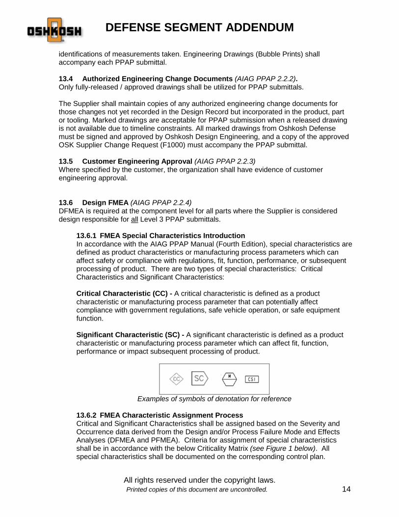
13.6.1 FMEA Special Characteristics Introduction In accordance with the AIAG PPAP Manual (Fourth Edition), special characteristics are defined as product characteristics or manufacturing process parameters which can affect safety or compliance with regulations, fit, function, performance, or subsequent processing of product. There are two types of special characteristics: Critical Characteristics and Significant Characteristics: Critical Characteristic (CC) - A critical characteristic is defined as a product characteristic or manufacturing process parameter that can potentially affect compliance with government regulations, safe vehicle operation, or safe equipment function. Significant Characteristic (SC) - A significant characteristic is defined as a product characteristic or manufacturing process parameter which can affect fit, function, performance or impact subsequent processing of product.
Examples of symbols of denotation for reference
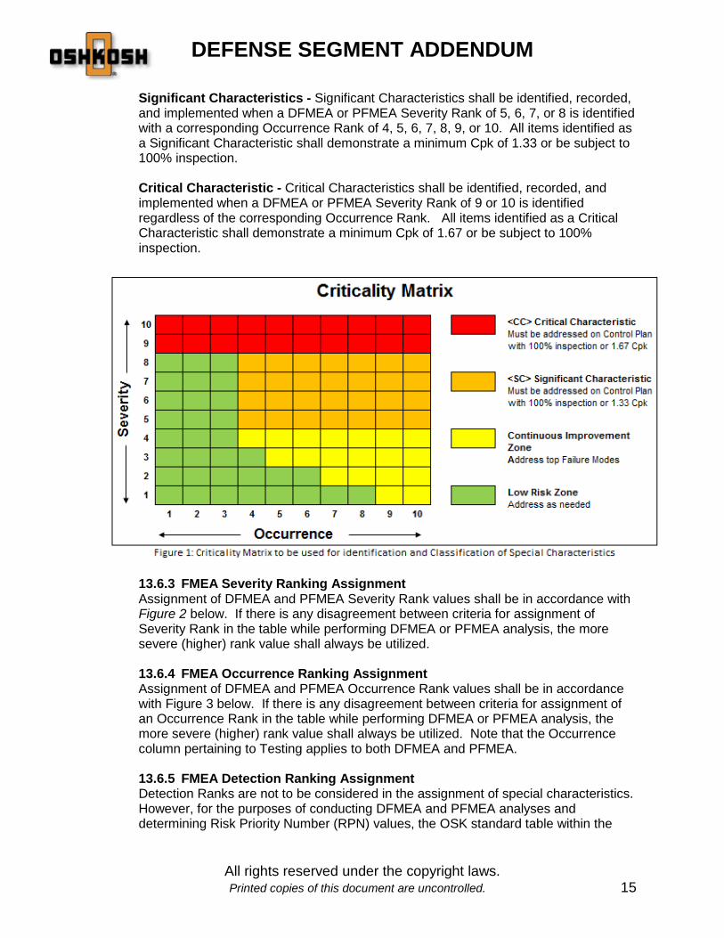
13.6.2 FMEA Characteristic Assignment Process Critical and Significant Characteristics shall be assigned based on the Severity and Occurrence data derived from the Design and/or Process Failure Mode and Effects Analyses (DFMEA and PFMEA). Criteria for assignment of special characteristics shall be in accordance with the below Criticality Matrix (see Figure 1 below). All special characteristics shall be documented on the corresponding control plan.
DEFENSE SEGMENT ADDENDUM
All rights reserved under the copyright laws. Printed copies of this document are uncontrolled. 15
Significant Characteristics - Significant Characteristics shall be identified, recorded, and implemented when a DFMEA or PFMEA Severity Rank of 5, 6, 7, or 8 is identified with a corresponding Occurrence Rank of 4, 5, 6, 7, 8, 9, or 10. All items identified as a Significant Characteristic shall demonstrate a minimum Cpk of 1.33 or be subject to 100% inspection. Critical Characteristic - Critical Characteristics shall be identified, recorded, and implemented when a DFMEA or PFMEA Severity Rank of 9 or 10 is identified regardless of the corresponding Occurrence Rank. All items identified as a Critical Characteristic shall demonstrate a minimum Cpk of 1.67 or be subject to 100% inspection.
13.6.3 FMEA Severity Ranking Assignment Assignment of DFMEA and PFMEA Severity Rank values shall be in accordance with Figure 2 below. If there is any disagreement between criteria for assignment of Severity Rank in the table while performing DFMEA or PFMEA analysis, the more severe (higher) rank value shall always be utilized.
13.6.4 FMEA Occurrence Ranking Assignment Assignment of DFMEA and PFMEA Occurrence Rank values shall be in accordance with Figure 3 below. If there is any disagreement between criteria for assignment of an Occurrence Rank in the table while performing DFMEA or PFMEA analysis, the more severe (higher) rank value shall always be utilized. Note that the Occurrence column pertaining to Testing applies to both DFMEA and PFMEA.
13.6.5 FMEA Detection Ranking Assignment Detection Ranks are not to be considered in the assignment of special characteristics. However, for the purposes of conducting DFMEA and PFMEA analyses and determining Risk Priority Number (RPN) values, the OSK standard table within the

DEFENSE SEGMENT ADDENDUM
All rights reserved under the copyright laws. Printed copies of this document are uncontrolled. 16
PPAP workbook (Table Cr3 from the AIAG Potential Failure Mode and Effects Analysis Manual Fourth Edition) shall be utilized.

DEFENSE SEGMENT ADDENDUM
All rights reserved under the copyright laws. Printed copies of this document are uncontrolled. 17

DEFENSE SEGMENT ADDENDUM
All rights reserved under the copyright laws. Printed copies of this document are uncontrolled. 18

DEFENSE SEGMENT ADDENDUM
All rights reserved under the copyright laws. Printed copies of this document are uncontrolled. 19
13.7 Process Flow Diagram (AIAG PPAP 2.2.5) Process Flow Diagrams are required for all Level 3 PPAP submittals.
13.8 Process FMEA (AIAG PPAP 2.2.6) PFMEAs are required for all Level 3 PPAP submittals. Additional FMEA requirements are outline in section 13.6
13.9 Control Plan (AIAG PPAP 2.2.7) Control Plans are required for all Level 3 PPAP submittals.
13.10 Measurement Systems Analysis (MSA) Studies (AIAG PPAP 2.2.8) For all Level 3 PPAP submittals, Oshkosh requires separate GR&R’s be submitted for each
DEFENSE SEGMENT ADDENDUM
All rights reserved under the copyright laws. Printed copies of this document are uncontrolled. 20
measurement gage or device family gage that is used to validate Special (Significant, Critical, Major or CSI) Characteristics identified on the Design Record or listed in the Control Plan.
Note: not all product and process characteristics listed in the Control Plan are expected
to require extensive measurement systems analysis scrutiny. Suppliers are encouraged to use a risk based approach when evaluating whether GR&R’s should be required for any non-Special Characteristic measurements listed in the Control Plan. However, where no Special Characteristics are identified in the Design Record or in the Control Plan, Oshkosh reserves the right to require MSAs and/or demonstration of Initial Process Capability on any other characteristics.
13.10.1 Definitions: • Measurement Systems are the collection of instruments or gages, standards,
operations, methods, fixtures, software, personnel, environment and assumptions used to quantify a unit of measure or fix assessment to the feature characteristic being measured.
• Gages are any devices used to obtain measurements or data (includes go/no-go
devices). • Device Family Gages are standard non-precision gages and measurement tools
(such as micrometers or calipers) that are of the same make and model. • Measurement System Analysis (MSA) is a mathematical method of
determining how much the variation within the measurement process contributes to overall process variability. MSA is used to ensure the use of the right measurement system for running production. Oshkosh requires suppliers to perform MSA in accordance with AIAG MSA Manual 4th edition. Additional training, analysis instruction, and worksheets are available within the PPAP workbook, and on the Oshkosh portal https://osn.oshkoshcorp.com/
• Gage Repeatability and Reproducibility (GR&R) is used to ensure that
measurements used in the manufacturing process are reasonably consistent regardless of how many times they are performed, or by who they are performed. GR&R can be useful to suppliers in that they can identify equipment that is in need of service, or operators who may need additional training on the equipment. In addition to repeatability and reproducibility (GR&R), MSA studies must also address bias, linearity and stability.
13.10.2 GR&R Requirements: The minimum number of appraisers, trials and parts when performing GR&R’s are as follows: • Variable data - 3 appraisers, 3 trials, 10 parts • Attribute data - 3 appraisers, 3 trials, 30 parts
Parts used in the study should represent the entire range of the tolerance. Whenever possible, the appraisers used to conduct the study should be the ones who normally perform the measurements in production. Measurements should be

DEFENSE SEGMENT ADDENDUM
All rights reserved under the copyright laws. Printed copies of this document are uncontrolled. 21
taken in the normal production location utilizing the production measuring equipment for the entire study. Assessment of the measurement system should be based on the Total Tolerance of the feature being measured (i.e. %GRR to TOLERANCE). Guidelines for measurement system acceptability are as follows (reference Table VIII-A): • The percent GRR should be less than 10% for gages used to measure Special
Characteristics • Gages whose percent GRR is between 10% to 30% may be acceptable for some
applications, but use of the gage must be approved by OSK Quality Engineering • Gages whose percent GRR is over 30% are considered unacceptable for the
application and cannot be used
GRR Decision
Less than 10 percent Gage considered to be acceptable for application
10 percent to 30 percent Gage may be acceptable for some applications. Use of gage must be approved by OSK
Over 30 percent Gage considered to be unacceptable for application
Table VIII-A: GR&R Criteria
13.10.3 Additional MSA Requirements All gages shall be properly calibrated. New MSA’s are to be conducted for all new devices used within studies. or modified gages / test equipment used within studies. It is recommended that GR&R’s be conducted annually. Any proposal to utilize an abbreviated GR&R must be pre-approved by OSK Quality Engineering. GR&R’s are also required for each measurement gage or device family gage that is used to validate Component First Article Test (CFAT) requirements. MSA’s for these gages and GR&Rs should be submitted with the PPAP.
13.11 Dimensional Results (AIAG PPAP 2.2.9) 100% dimensional inspection is required for a minimum of three (3) parts for each Level 3 PPAP submittal. 100% dimensional inspection is required for a minimum of one (1) part for each Level 2 PPAP submittal. One (1) piece dimensional results are required for any subcomponent outlined on the drawing being purchased for each Level 2 or Level 3 PPAP submittal.
Dimensional results for PPAP must be taken from production parts. For production parts that are produced from more than one die, mold, tooling, pattern, cavity or production process, the Supplier shall complete full dimensional layouts from each.
Measuring equipment should have a discrimination of at least one-tenth of the total tolerance being measured (AIAG MSA, chpt. 1 sect. E)
13.12 Records of Material / Performance Test Results (AIAG PPAP 2.2.10)
DEFENSE SEGMENT ADDENDUM
All rights reserved under the copyright laws. Printed copies of this document are uncontrolled. 22
13.12.1 Material Test Results It is the Supplier’s responsibility to confirm the conformance of their material to applicable standards for PPAP submission. The Supplier shall perform all chemical, physical, metallurgical, or mechanical property tests for all parts and product materials when chemical, physical, metallurgical or mechanical property requirements are specified by the Design Record or Control Plan. Examples of Material Test Results that are required for all PPAP submittals include: raw material certifications, painting, plating, heat-treating, welding (documentation necessary to demonstrate conformance to specified weld requirements such as Weld Procedure Qualification Requirements), etc. When the supplier maintains “design record authority” for the part (and sub-component parts), and material details are not documented on the design record, OSK requires all material test results (with Qualified Lab documentation) to be maintained by the supplier and made available to OSK upon request. Material test results may be presented on any AIAG compliant form (the OSK PPAP workbook also includes a template). Raw material composition result should be presented in a Certificate of Analysis (COA) form. Qualified Lab documentation must accompany each material test result form (reference the Qualified Lab Documents section of this Addendum).
Materials test results shall indicate and include: • The design record change level of the parts tested • Any authorized engineering changes that have not yet been incorporated into the
design record (if applicable) • The number, date, and change level of the specifications to which the part was
tested • The date on which the testing took place • The quantity tested • The specified parameters and actual results • The material supplier’s name
13.12.2 Performance Test Results The Supplier shall perform appropriate tests when performance or functional requirements are specified by the design record or Control Plan. The Supplier shall use the performance test form provided in the OSK PPAP workbook to document and submit the performance test results. Qualified Lab documentation must accompany each performance test result form (reference the Qualified Lab Documents section of this Addendum). Performance test results shall indicate and include the following: • The design record change level of the parts tested • Any authorized engineering changes that have not yet been incorporated into the
design record (if applicable)
DEFENSE SEGMENT ADDENDUM
All rights reserved under the copyright laws. Printed copies of this document are uncontrolled. 23
• The number, date, and change level of the specifications to which the part was tested
• The date on which the testing took place • The quantity tested • The specified parameters and actual results
Welding Procedure Specifications (WPS), and Procedure Qualification Records (PQRs) shall be included within the PPAP submittal when applicable, and shall be stamped / signed, dated as “approved” by a Qualified Welding Inspector (see 11.6).
13.12.3 On-going Testing It is the Supplier’s responsibility to plan for ongoing material and performance testing and to identify these as separate line items in the Control Plan. This ensures that the Supplier has a plan for continual conformance to the requirements. The interval of inspection is to be recommended by the Supplier, however, Oshkosh reserves the right to request a change in the frequency of this inspection
13.13 Initial Process Studies (AIAG PPAP 2.2.11) Initial Process Studies are required for all Level 3 PPAP submittals where Special (Significant, Critical, Major or CSI) Characteristics identified on the Design Record or listed in the Control Plan. 100% inspection is required until Cpk minimums are achieved.
• All Major or Critical Characteristics shall demonstrate a minimum Cpk of 1.67. • All Significant Characteristics shall demonstrate a minimum Cpk of 1.33. • 100% inspection to be conducted until Cpk thresholds met.
o Inspections to be reflected within the supplier’s Process Control Plan o Records as evidence of 100% inspection to be maintained, and submitted
upon request
The requirements for Significant Production Runs and Quality Indices shall be in accordance with PPAP Manual (Fourth Edition) Appendix H. All other PPAP Manual 2.2.11 requirements apply as written in the PPAP Manual (Fourth Edition). Where no Special Characteristics are identified in the Design Record or in the Control Plan, Oshkosh reserves the right to require demonstration of Initial Process Capability on any other characteristics.
13.14 Qualified Laboratory Documentation (AIAG PPAP 2.2.12) Material or Performance Tests for PPAP shall be performed by a qualified laboratory. If Material or Performance Tests are performed by an Internal or External Lab that:
IS NOT accredited, the Supplier must provide: • The name of the laboratory that performed the test • Documentation (work instruction) for each type of test conducted. • Training records / certifications of personnel who performed the testing (to show
competency) • List of all test equipment used to perform testing • Calibration records of all test equipment used

DEFENSE SEGMENT ADDENDUM
All rights reserved under the copyright laws. Printed copies of this document are uncontrolled. 24
• The date on which the testing took place IS accredited, the Supplier shall submit the test results on the laboratory letterhead or in the normal laboratory report format. The laboratory report must include: • The name of the laboratory that performed the test • The laboratory’s accreditation standard (and accreditation number and/or name of
the 3rd party organization that provided accreditation) o Note: OSK expects that all accredited labs be accredited to a known lab
accreditation standard such as ISO 17025 • List of standards used for testing • The date on which the testing took place
13.15 Appearance Approval Report (AAR) (AIAG PPAP 2.2.13) AAR’s are only required when requested by Oshkosh Quality Engineering representative. Note: Paint and/or Coating requirements are covered by section 13.10 Material Test Results.
13.16 Sample Production Parts (AIAG PPAP 2.2.14) The Supplier shall ensure that the “PPAP Parts Label” is filled out and attached appropriately to the outside of each package. Label should be in plain view of a fork lift / material handler / operator. In the event parts are “Loose” shipped, a label should be placed on each part (this would also apply to parts lying on pallets). Label on a painted part must be wire tied or attached in a way such that the painted surface is protected from label adhesion.
13.17 Master Sample (AIAG PPAP 2.2.15) A master sample is not required to be retained by the supplier unless specifically requested by OSK, however, the Supplier is required to photo document a Master Sample for all PPAP submittals. Photo documentation should illustrate how the parts will look like in the final state in which they are provided to Oshkosh. Specific focus of photo documentation should be on part labeling (to include any date codes, vendor codes, etc. if applicable), no paint zones if applicable.
13.18 Checking Aids (AIAG PPAP 2.2.16) Checking aids include all instruments, templates, attribute and variable gages, fixtures, or jigs that are used to determine acceptance/rejection of a product characteristic. The Supplier shall certify that all aspects of the checking aid agree with part dimensional requirements. The supplier shall document all released engineering design changes that have been incorporated in the checking aid at the time of PPAP submission. The supplier shall provide for preventative maintenance of any checking aids for the life of the part. In the event that a checking aid is used to verify a Special Characteristic, the Supplier shall conduct the appropriate MSA activities including Gage R&R (reference section 13.8).
13.19 Customer Specific Requirements (AIAG PPAP 2.2.17)

DEFENSE SEGMENT ADDENDUM
All rights reserved under the copyright laws. Printed copies of this document are uncontrolled. 25
If Component First Article Test (CFAT) is required per the Design Record, CFAT testing documentation shall be included with the PPAP submission.
13.20 Part Submission Warrant (PSW) (AIAG PPAP 2.2.18) PSW’s are required for all PPAP submissions. It is recommended that suppliers utilize the OSK version of the PSW. Equivalent forms may be considered.
DEFENSE SEGMENT ADDENDUM
All rights reserved under the copyright laws. Printed copies of this document are uncontrolled. 26
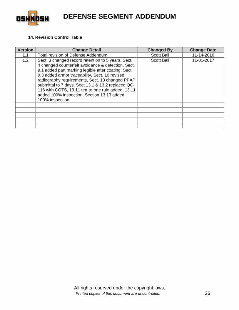
14. Revision Control Table
Version Change Detail Changed By Change Date 1.1 Total revision of Defense Addendum Scott Ball 11-14-2016 1.2 Sect. 3 changed record retention to 5 years, Sect.
4 changed counterfeit avoidance & detection, Sect. 9.1 added part marking legible after coating, Sect. 9.3 added armor traceability, Sect. 10 revised radiography requirements, Sect. 13 changed PPAP submittal to 7 days, Sect.13.1 & 13.2 replaced QC-116 with COTS, 13.11 ten-to-one rule added, 13.11 added 100% inspection, Section 13.13 added 100% inspection,
Scott Ball 11-01-2017