global fire resistance warm springs composite …...the legal validity of this report can only be...
TRANSCRIPT

The legal validity of this report can only be claimed on presentation of the complete report
Report for: Warm Springs Composite Products Ref: Chilt/A06218 Revision E
Page 1 of 38
Global Fire Resistance
Assessment
Sponsor:
Warm Springs Composite Products
PO Box 906
Warm Springs
Oregon 97761
USA CONFIDENTIAL
Report: Chilt/A06218 Revision E
Contract: CNA/F15171
Warm Springs Composite Products 60, 90 & 120
Minute Fire Resisting Doorsets
Valid From: 16th October 2015
Valid Until: 16th October 2020
Page 1 of 38 This document is confidential and remains the property of Chiltern International Fire Ltd. The legal validity of this report can only be claimed on the
presentation of the complete report.

The legal validity of this report can only be claimed on presentation of the complete report
Report for: Warm Springs Composite Products Ref: Chilt/A06218 Revision E
Page 2 of 38
Contents
Page No.
1 Introduction .................................................................................................................... 3
2 General Description of Construction ............................................................................... 3
3 Leaf Sizes ...................................................................................................................... 5
4 Configurations ................................................................................................................ 5
5 Leaf Size Adjustment ..................................................................................................... 5
6 Overpanels & Side Panels ............................................................................................. 6
7 Glazing ........................................................................................................................... 8
8 Door Frames ................................................................................................................ 12
9 Edging Materials .......................................................................................................... 14
10 Leaf Facing Materials ................................................................................................... 14
11 Intumescent Materials .................................................................................................. 17
12 Adhesives .................................................................................................................... 17
13 Tested Hardware .......................................................................................................... 18
14 Additional & Alternative Hardware ................................................................................ 18
15 Door Gaps .................................................................................................................... 21
16 Structural Opening ....................................................................................................... 21
17 Fixings ......................................................................................................................... 21
18 Sealing to Structural Opening ....................................................................................... 22
19 Insulation...................................................................................................................... 23
20 Smoke Control ............................................................................................................. 23
21 Conclusion ................................................................................................................... 23
22 Declaration by the Applicant ......................................................................................... 24
23 Limitations .................................................................................................................... 25
24 Validity ......................................................................................................................... 25
Appendix A - Performance Data 26
Appendix B - Tested Glazing System 28
Appendix C - Tectonite Door Frame Constructions 29
Appendix D - Revisions 31
Appendix E - Data Sheets 32

The legal validity of this report can only be claimed on presentation of the complete report
Report for: Warm Springs Composite Products Ref: Chilt/A06218 Revision E
Page 3 of 38
1 Introduction
This document constitutes a fire resistance assessment relating to composite doorsets, for Warm Springs Composite Products (WSCP). The assessment uses established extrapolation and interpretation techniques in order to extend the scope of application by determining the limits for the designs, based on the tested constructions and performances obtained. The assessment is an evaluation of the potential fire resistance performance, if the elements were to be tested in accordance with BS 476: Part 22: 1987.
2 General Description of Construction
The primary construction for door leaves covered by this assessment comprises the following:
2.1 WSCP Design
This door design comprises the following elements and is for 60, 90 and 120 minute fire resisting applications:
Element Material Dimensions (mm) Min. Density (kg/m3)
Stiles Tectonite Min. 25 (w) x 51 (t)
1000 ±10* Max. 43 (w) x 51 (t)
Rails (top & bottom) Tectonite Min. 51 (w) x 51 (t)
1000 ±10* Max. 102(w) x 51(t)
Core WSCP mineral core 51 thick 288 ±30*
Facings
Option 1 MDF 3 thick 750**
Option 2 HDF 3 thick 820**
Option 3 Plywood 3 thick 640**
Option 4 Chipboard 3 thick 640**
Lippings Hardwood 3 – 4 thick 640*
Adhesives (facings, lippings, internal framing, core)
See section 12 - -
* Stated by the client. ** Nominal density.
2.2 Multi-Piece Core, Stiles & Rails
2.2.1 Multi-Piece Core
The testing conducted on the designs tested in CFR1007071, CFR1007081, CFR1009081 and CFR1103111 used door cores comprising multiple pieces (between 3 & 7). It is therefore permitted to construct the WSCP design using multiple pieces of core up to a maximum number of 7 individual pieces and providing they are glued together using cross-linked PVA. The pieces may be rectangular or square, of different dimensions to suit the door construction.
The legal validity of this report can only be claimed on presentation of the complete report
Report for: Warm Springs Composite Products Ref: Chilt/A06218 Revision E
Page 4 of 38
2.2.2 Multi-Piece Stiles & Rails
The testing conducted on a sample of door leaf under WHI 495 PSV 1553 demonstrated that the Warm Springs design, when constructed with multi-piece stiles and rails, was capable of providing a minimum of 90 minutes fire resistance when tested to the time temperature curve specified in UBC Standard 7-2 (1997): Fire Tests of Door Assemblies. The door was further subjected to a hose stream that lasted 28 seconds.
Although the sample of door was subjected to a US test method, it can be used as suitable evidence to demonstrate the WSCP design can be constructed with multi-piece Tectonite stiles and rails meeting the following specification for 60 and 90 minutes fire resistance only:
1. Lengths of stiles and rails must be no shorter than 400mm.
2. The sections of stiles and rails must be glued together using cross-linked PVA.
NB: 120 minute fire resisting designs must use continuous lengths of Tectonite for the stiles and rails; jointed sections are not permitted.
2.3 Banded Door Core & Components
The WSCP design described in section 2.1 can be supplied by Warm Springs Composite Products as Banded Door Cores (BDC) or as separate components to be constructed by the end user. In either case, the door cores are to be constructed in strict accordance with the specification given in this global assessment.
2.4 Enhanced Acoustic Performance
It is permitted to alter the construction of the WSCP design to provide for enhanced acoustic performance, subject to the following provisos:
1. The outer facing may be increased to 6mm thick (MDF only).
2. Single leaf constructions only.
3. All leaf dimensions (for single leaf configurations) given in the data sheets contained in Appendix E are permitted at 60 and 90 minutes fire resistance.
4. For 120 minutes performance, the maximum permitted single leaf dimensions are 2292mm (h) x 1068mm (w).
5. Norseal NOR810s drop seal may be fitted in the bottom rail subject to the intumescent gasket remaining in the bottom of the leaf as specified in section 11.3 (intumescent seal will be interrupted by the fitting of the drop seal).
6. Norseal NOR710 may be fitted around the perimeter of the leaf providing the intumescent specification required in section 11.3 is not altered.
7. All other details to remain as specified in this assessment for the WSCP design.

The legal validity of this report can only be claimed on presentation of the complete report
Report for: Warm Springs Composite Products Ref: Chilt/A06218 Revision E
Page 5 of 38
3 Leaf Sizes
The approval for increased leaf dimensions is based on the tests listed in Appendix A and takes into account the margin of over-performance above 60, 90 & 120 minutes integrity (as applicable) for the design and the characteristics exhibited during test. Data sheets specifying the maximum approved leaf sizes and graphs showing the permitted gradient between maximum height and width are contained in Appendix E.
Doorsets with reduced dimensions are deemed to be less onerous. Therefore, doors with dimensions that are less than those tested and stated in Appendix E may be manufactured. Unequal leaf double doorsets are covered by this assessment with no restriction on the smaller leaf dimension.
4 Configurations
Based on the test evidence listed in Appendix A, this assessment covers the following doorset configurations:
4.1 60 Minutes Fire Resistance
Abbreviation Description
LSASD & ULSASD Latched & unlatched, single acting, single doorsets
DASD Double acting, single doorsets
LSADD & ULSADD Latched & unlatched, single acting, double doorsets
DADD Double acting, double doorsets
4.2 90 & 120 Minutes Fire Resistance
Abbreviation Description
LSASD & ULSASD Latched & unlatched, single acting, single doorsets
LSADD & ULSADD Latched & unlatched, single acting, double doorsets
5 Leaf Size Adjustment
The WSCP design door leaves may be altered as follows:
Element Reduction
Leaf The manufactured size of the leaf may be adjusted at any edge providing the stiles are not reduced below 25mm (w) and the rails are not reduced below 51mm (w) and the lipping is replaced in accordance with section 9.1
Lipping The dimensions stated in section 9.1 may be reduced by 20% for fitting purposes.

The legal validity of this report can only be claimed on presentation of the complete report
Report for: Warm Springs Composite Products Ref: Chilt/A06218 Revision E
Page 6 of 38
6 Overpanels & Side Panels
6.1 Overpanels
Overpanels of the same construction as the door leaves may only be used when separated by a transom. The overpanel must be fully contained within the door frame (see following diagram).
The transom required to separate the leaf heads from the overpanel must be to the same specification as the door frame (see the note under the table in section 8.1).
Door frame joints must utilise one of the following methods: mortice and tenon joints or butt joints (see section 8.2).
Both methods require joints to be tight, with no gaps, and require mechanical fixing with a minimum of 3No. nail or screw fixings penetrating by a minimum of 40mm and additionally bonded with cross-linked PVA or urea/resorcinol formaldehyde.
The overpanels must be fixed by screwing through the rear of the frame with coarsely threaded wood-type steel screws passing at least 40mm into the centre line of the overpanel. Fixings must be no more than 100mm from each corner and a maximum of 250mm centres in between. The intumescent seals specified for the jambs in Appendix E, must also be fitted to all concealed edges of the overpanel. The seals may be fitted in the overpanel edges or alternatively in the frame reveal.
Maximum overpanel heights are as follows:
Configuration Max. Overpanel Height (mm)
Single doorsets 500
Double doorsets 500
Note: Drawing is representative of doorset construction only; actual construction must be as the text within this document specifies.
Overpanel fixings
Door leaf
Transom
Intumescent seals

The legal validity of this report can only be claimed on presentation of the complete report
Report for: Warm Springs Composite Products Ref: Chilt/A06218 Revision E
Page 7 of 38
6.2 Side Panels
Side panels of the same construction as the door leaves may be used with this doorset design meeting the following specification:
1. Side panels may only be used with single leaf doorsets.
2. The swinging leaf must be hung from the door frame that is directly fixed back to the structural opening (i.e. it is not permitted to hang the leaf from the frame that separates the side panel from the leaf).
3. The maximum permitted dimensions of the side panel are for the height of the leaf and no more than 500mm in width.
4. The side panel must be located in the same plane as the door leaf.
5. The side panel may be used in conjunction with an overpanel providing the overpanel is located above the side panel, including a separating transom and the overall assembly is no wider than 1500mm in total.
6. The frame separating the side panel and door leaf must be of the same section and material assessed for the door frames, mortice and tenon or butt jointed to the frame head (with no gaps), bonded with cross-linked PVA or urea/resorcinol formaldehyde and fixed with a minimum of 3No. steel fixings penetrating by a minimum of 40mm (see section 8.1 for additional information on frame specification).
7. The side panel must be fixed by screwing the rear of the frame with coarsely threaded wood-type steel screws passing at least 40mm into the centreline of the side panel. Fixings must be no more than 100mm from each corner and a maximum of 250mm centres in between.
8. The intumescent seals specified for the jambs in Appendix E must be fitted to all edges of the side panel. The seals may be fitted in the side panel edges or alternatively in the frame reveal.

The legal validity of this report can only be claimed on presentation of the complete report
Report for: Warm Springs Composite Products Ref: Chilt/A06218 Revision E
Page 8 of 38
7 Glazing
7.1 Option 1 (up to 120 minutes)
The test referenced Warres 63295 was conducted on a similar composite door construction to the WSCP design and was fitted with a Lorient Polyproducts Ltd. 120 minute glazing system.
Based on the equivalence of the door constructions and the 24% margin of overrun in performance achieved by the glazing system, we consider that the Lorient FD120 system can be used for glazing the WSCP design. The maximum assessed glazed area when using this system is 0.18m2.
The approved system is to be installed as follows:
Element Product Dimensions (mm) Location
Glass type Firelite ceramic
glass 5 thick
Fitted a minimum of 115mm from leaf head & 115mm
from meeting/closing edge
Expansion allowance
- 2 – 3 all edges -
Beading 1.2 thick
stainless steel ‘Z’ section
25 over door face Fitted on both faces around the perimeter of the glazing
aperture & mitred at the corners
11 return across reveal
22 upstand to glass
Bead fixings Min. of 3No.
bolts per length M6 x length required to
pass through leaf
Through cover bead face with a fixing no more than 75mm from each corner
Glazing system
Lorient System 90+ ‘U’ channel
- Fitted to cradle the glass
Aperture liner
Palusol 100P 2 thick Fitted lining the full width of
the glazed aperture
Notes:
1. Glazed opening must not be less than 115mm from any door leaf edge.
2. Multiple apertures are acceptable within the permitted glazed area, with a minimum dimension of 100mm between apertures.
3. Aperture shape is restricted to square or rectangular.
4. A sectional drawing detailing the assessed glazing system is contained in Appendix B.
7.2 Option 2 (up to 90 minutes)
The test referenced Chilt/IF12047 was conducted on the WSCP design and was fitted with a Norseal Ltd. Norglaze Universal 90 glazing system.
Based on the overrun in performance achieved by the glazing system, we consider that the Norglaze Universal 90 glazing system can be used for glazing the WSCP doorset design for up to 90 minute fire resisting applications. The maximum assessed glazed area when using this system is 0.18m2.
The approved system is to be installed as follows:

The legal validity of this report can only be claimed on presentation of the complete report
Report for: Warm Springs Composite Products Ref: Chilt/A06218 Revision E
Page 9 of 38
Element Product Dimensions (mm) Location
Glass type Schott Pyran S 6 thick Fitted 165mm from the leaf
head & vertical edges
Expansion allowance
- 3 all round -
Beading
Profiled aluminium cover trim
24 (h) x 26 (d) overall
Fitted around the glazing aperture on both faces
Tectonite bead
12 (t) x 22 (d) Fitted under the cover trim
on both faces
Tectonite bead
fixings
PVA adhesive & steel screws
15 long
Fixed through the bead into the glazing fixing pads at 150mm nominal centres
& 50mm from corners
Cover trim fixings
12No. fixing pads/clips on each face – profiled
aluminium
50 (w) x 20 (d) x 3 (t) with a 1 (w) x 8 (d) slot in the outer
edge
3No. fitted on each edge 50mm from corners &
1No. central in height/width, fixed with
2No. 15mm (l) steel screws per clip
Cover trim fixings
12No. fixing tabs on each face – profiled aluminium
30 (w) x 10 (d) x 1.9 (t) overall
Fitted through the cover trim into slot in the outer face of the cover trims

The legal validity of this report can only be claimed on presentation of the complete report
Report for: Warm Springs Composite Products Ref: Chilt/A06218 Revision E
Page 10 of 38
Glazing Bead System
Notes:
1. Glazed opening must not be less than 165mm from any door leaf edge.
2. Multiple apertures are acceptable within the permitted glazed area, with a minimum dimension of 100mm between apertures.
3. Aperture shape is restricted to square or rectangular.
Tectonite lining glazed aperture
Cover trim
Tectonite bead
Tectonite bead fixing
Fixing pad/clip
Fixing tab
Fixing pad/clip screw
The legal validity of this report can only be claimed on presentation of the complete report
Report for: Warm Springs Composite Products Ref: Chilt/A06218 Revision E
Page 11 of 38
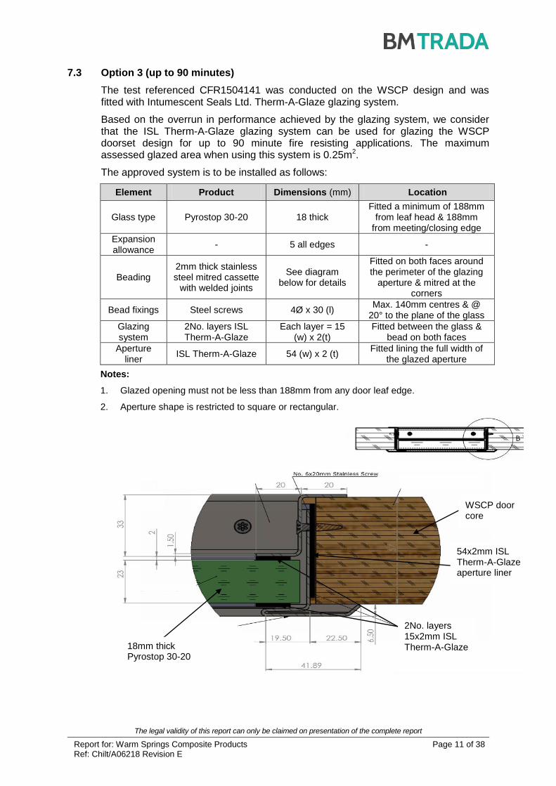
7.3 Option 3 (up to 90 minutes)
The test referenced CFR1504141 was conducted on the WSCP design and was fitted with Intumescent Seals Ltd. Therm-A-Glaze glazing system.
Based on the overrun in performance achieved by the glazing system, we consider that the ISL Therm-A-Glaze glazing system can be used for glazing the WSCP doorset design for up to 90 minute fire resisting applications. The maximum assessed glazed area when using this system is 0.25m2.
The approved system is to be installed as follows:
Element Product Dimensions (mm) Location
Glass type Pyrostop 30-20 18 thick Fitted a minimum of 188mm
from leaf head & 188mm from meeting/closing edge
Expansion allowance
- 5 all edges -
Beading 2mm thick stainless steel mitred cassette
with welded joints
See diagram below for details
Fitted on both faces around the perimeter of the glazing
aperture & mitred at the corners
Bead fixings Steel screws 4Ø x 30 (l) Max. 140mm centres & @
20° to the plane of the glass
Glazing system
2No. layers ISL Therm-A-Glaze
Each layer = 15 (w) x 2(t)
Fitted between the glass & bead on both faces
Aperture liner
ISL Therm-A-Glaze 54 (w) x 2 (t) Fitted lining the full width of
the glazed aperture
Notes:
1. Glazed opening must not be less than 188mm from any door leaf edge.
2. Aperture shape is restricted to square or rectangular.
18mm thick Pyrostop 30-20
WSCP door core
2No. layers 15x2mm ISL Therm-A-Glaze
54x2mm ISL Therm-A-Glaze aperture liner

The legal validity of this report can only be claimed on presentation of the complete report
Report for: Warm Springs Composite Products Ref: Chilt/A06218 Revision E
Page 12 of 38
8 Door Frames
8.1 Door Frame Construction
Door frames for the WSCP doorset design must be constructed to meet the following specification:
Material Minimum Section Size (mm) Min. Density (kg/m3)
Hardwood* 90 (w) x 38 (t) (excluding the stop) 640
Tectonite
(2 or 4mm hardwood or MDF veneer)
94 (w) x 43 (t) (excluding the stop) 1000 ±10
Tectonite
(Hardwood composite)
112 (w) x 47 (t) (excluding the stop)
(Overall frame dimension; see Appendix C for construction)
Tectonite = 1000 ±10
Hardwood = 680
Notes:
* Hardwood door frames are permitted for all assessed leaf configurations and all assessed leaf sizes for 60 and 90 minute applications. For 120 minute applications, hardwood door frames are permitted for all assessed leaf sizes but restricted to single leaf doorsets only.
If the doorset features a transomed overpanel, the door frame must meet the following specification:
Hardwood (min. density 680kg/m3) – 90mm (w) x 45mm (t) – Single leaf WSCP Design for 120 minutes fire resistance only.
Hardwood (min. density 680kg/m3) – 90mm (w) x 45mm (t) – Single & double leaf WSCP Design for 60 & 90 minutes fire resistance only.
Tectonite (2 or 4mm hardwood veneer or hardwood composite) – Single & double leaf WSCP Design.
All door frame timber must be straight grained, joinery quality, free from knots, splits and checks.
A 12mm deep stop, planted or rebated from solid is adequate for single acting frames. It is permitted to fix a planted stop through the rear of the frame using a suitable fixing for the frame material. The fixing must penetrate the stop to a depth of 8mm.
A planted stop may be hardwood or Tectonite meeting the specification in the table above for 60, 90 or 120 minutes fire resistance.
A T-Stop planted stop detail is acceptable and is depicted in Appendix C.
Timber frame joints may be mortice and tenon, mitred, half lapped or butted and with no gaps. All jointing methods require mechanical fixing with the appropriate size ring shank nails or screws.
Tectonite frame joints must be butt jointed or mortice and tenoned with 3No. coarsely threaded wood-type steel screws per joint. The Tectonite must have pilot holes drilled in order to facilitate construction (and the fitting of hardware).
It is possible to extend the width of the 94mm (w) Tectonite frame by joining a section of hardwood using either a butt joint or tongue and grooved joint.
See Appendix C for details on the 2No. Tectonite door frame constructions.

The legal validity of this report can only be claimed on presentation of the complete report
Report for: Warm Springs Composite Products Ref: Chilt/A06218 Revision E
Page 13 of 38
8.2 Door Frame Joints
Half Lapped Joint Mitre Joint
Mortice & Tenon Joint Butt Joint
Note: Drawing is representative of each type of door frame joint only; actual construction in terms of intumescent seal location and material, etc. must be as the text within this document specifies.
A = Min. 90 - 112mm (see table above) B = Min. 38 - 47mm (see table above) C = Min. 12mm
Standard

The legal validity of this report can only be claimed on presentation of the complete report
Report for: Warm Springs Composite Products Ref: Chilt/A06218 Revision E
Page 14 of 38
8.3 Door Frame Installation
The following diagrams indicate the permitted types of door frame installation (see section 17 for suitable frame fixing details and section 18 for sealing to structural opening):
6 to 10mm
Max 10 x 10mm shadow gap with 2mm
intumescent mastic capping or
10 x 4mm PVC encased intumescent seal
15mm
Permitted Permitted
PermittedNot PermittedNot Permitted
Permitted
6 to 10mm
Max 10 x 10mm shadow gap with 2mm
intumescent mastic capping or
10 x 4mm PVC encased intumescent seal
15mm
Permitted Permitted
PermittedNot PermittedNot Permitted
Permitted
Frame installation with architrave Frame installation without architrave
9 Edging Materials
9.1 Timber Lippings
The WSCP design must be lipped in accordance with the following specification:
Material Size (mm) Min. Density (kg/m3)
Timber must be straight grained, joinery quality hardwood, free from knots, splits and checks
Flat = 3 - 4 thick with a maximum of 2mm profiling permitted at corners of lipping.
640
Notes:
1. Rebated leaf edges are not permitted.
2. Door leaves must be lipped on the vertical edges, and may additionally be lipped on the horizontal edges, if required.
10 Leaf Facing Materials
10.1 General
Based on the type and thickness of the external facing materials tested for the WSCP design, the following facing materials are approved:
Facing Material Max. Permitted Thickness (mm) Min. Density (kg/m³)
MDF
3 – 4
(6mm is permitted for acoustic applications – see section 2.4)
750
HDF 3 – 4 820
Plywood 3 – 4 680
Chipboard 3 - 4 640

The legal validity of this report can only be claimed on presentation of the complete report
Report for: Warm Springs Composite Products Ref: Chilt/A06218 Revision E
Page 15 of 38
10.2 Decorative & Protective Facings
The following additional facing materials are permitted for this door design since they would degrade rapidly under test conditions without significant effect:
Facing Materials Maximum Permitted Thickness (mm)
Paint 0.5
Timber veneers 2
PVC/Plastic laminates 2
Decorative paper/Non-metallic foil 0.5
Notes:
1. Metallic facings are not permitted except for push plates and kick plates (see section 14.5).
2. The door leaf thickness may be reduced by a total maximum of 0.5mm for calibration purposes, only in order to accommodate one of the additional facings shown in the table above.
3. Materials must not conceal intumescent strips.
4. PVC/plastic laminates must not be applied to leaf edges.
10.3 Decorative Grooves
The outer facing has been deemed as having negligible influence on the structural stability of the door design. It is therefore permitted to groove/recess both faces of the door leaf with any decorative pattern subject to the following provisos:
1. The amount of material removed from any one face must not exceed 30%.
2. The depth of the groove/recess must not exceed 3mm.
3. The groove/recess may run to the leaf edge.
4. The groove/recess must not coincide with any glazed apertures, i.e. the groove or recess must stop short of the beading system for the glass.
The following picture provides an example of the type of pattern this groove/recess option would permit:

The legal validity of this report can only be claimed on presentation of the complete report
Report for: Warm Springs Composite Products Ref: Chilt/A06218 Revision E
Page 16 of 38
10.4 Decorative Grooves with Aluminium Inserts
The WSCP design may be grooved to the following specification and fitted with an aluminium insert:
Element Details
Max. Groove Size (mm) 10 wide x 4 deep
Proximity to Leaf Edges (mm) Horizontal Grooves ≥150 from top & bottom
Vertical Grooves ≥150 from sides
Groove Spacing (mm) ≥150
Orientation Vertical or horizontal
Configuration Latched & unlatched, single acting, single & double leaf doorsets
Leaf Size Range (mm) All
Notes:
1. The grooves must not coincide with any glazed apertures.
2. A maximum of 4No. vertical and 4No. horizontal grooves are permitted perpendicular and intersecting one another providing all other details meet the specification given in the table above.
3. The grooves may run to the leaf edges.
4. To accommodate the aluminium insert the outer facing for the WSCP design must be increased to a minimum of 5mm thick. The groove may be a maximum of 4mm deep and all other details must remain as specified in the table above.

The legal validity of this report can only be claimed on presentation of the complete report
Report for: Warm Springs Composite Products Ref: Chilt/A06218 Revision E
Page 17 of 38
11 Intumescent Materials
The intumescent materials tested and assessed for the WSCP design are as follows:
Application Make/type Size (mm) Location
Leaf edges
Head None fitted - -
Hanging edges None fitted - -
Leaf edges
Meeting edges
Left leaf
WSCP PVC-seal 22 x 4 Set within a groove 5mm from the exposed face
Right leaf
WSCP PVC-seal 22 x 4 Set within a groove 5mm from the unexposed face
Bottom of leaf WSCP Flex-seal (uncased graphite)
47 x 1 Fitted centrally in a groove in the leaf and over sailing the lippings
Frame reveal
Head WSCP PVC-seal
22 x 4 Set within a groove 7mm from the exposed face
22 x 4 Set within a groove 33 from the exposed face
Jambs WSCP PVC-seal
22 x 4 Set within a groove 7mm from the exposed face
22 x 4 Set within a groove 33 from the exposed face
Under hinge blade WSCP Strip-seal 2 thick Under both hinge blades of all hinges
Under latch forend WSCP Flex-seal 1 thick Fitted under latch forend
Under latch strike WSCP Flex-seal 1 thick Fitted under latch strike (also at base of latch & lock rebates in frame)
12 Adhesives
The following adhesives must be used in construction of the WSCP design:
Element Product
Facings Cross linked PVA
Lipping Cross linked PVA or Hotmelt adhesive
Internal framing (stiles & rails) Cross linked PVA
Core (bonded to perimeter framework) Cross linked PVA
Notes:
1. The adhesive spread rate recommendation for the facings of 200-300g/m2 is within the
tested tolerances declared by the manufacturer.
2. The adhesive must be applied directly to the facing material and not the mineral core due to the porosity and absorption rate of the mineral core and for controlling the spread rate being used (as listed above).

The legal validity of this report can only be claimed on presentation of the complete report
Report for: Warm Springs Composite Products Ref: Chilt/A06218 Revision E
Page 18 of 38
13 Tested Hardware
The following hardware has been successfully incorporated in the tests on the WSCP doorset design:
Element Manufacturer & Product Reference
Hinges
1. Royde & Tucker H105 lift-off type hinges
2. Royde & Tucker H207 lift-off type hinges
3. Hoppe UK Ltd. bearing-butt type hinges; Ref: AR8680
4. Cooke Brothers Ltd. bearing-butt type hinges; Ref: 7700
Closers
1. Dorma TS83V overhead closer
2. Briton 2003SES overhead closer
3. Hoppe UK Ltd. concealed overhead closer; Ref: AR73831
Locks & latches
1. 5 Lever Legge lock/latch
2. Dorma 752F sash lock & Dale NP30/10/30 double cylinder 7200
3. Dale 97170 tubular mortice latch
4. Hoppe UK Ltd. mortice sashlock; Ref: AR910
5. Hoppe UK Ltd. stainless steel eurocylinder; Ref: E42S
6. Hoppe UK Ltd. lock escutcheon plate; Ref: AR361/27
7. Zoo Architectural Hardware Ltd. steel latch; Ref: ZDL CE1121
Furniture
1. Aluminium lever handles
2. Necked barrel bolt (code 5528)
3. Hoppe UK Ltd. stainless steel handle; Ref: E138Z/42
4. Hoppe UK Ltd. steel lever handle; Ref: AR361/10
5. Zoo Architectural Hardware Ltd. steel flush bolts; Ref: ZAS 03 SS
6. Turentek Architectural steel lever handle; Ref: Ovation OV 75.001
Note:
1 The Hoppe UK Ltd. concealed overhead closer; Product Reference AR7383, may only be
used when the slide arm body and closer body are fully encased with 2mm thick Interdens from Lorient Polyproducts Ltd. or Dufaylite Developments Ltd. (see section 14.3).
14 Additional & Alternative Hardware
The following section details the permitted scope and constraints for fitting hardware to this door design.
The following items of hardware must also bear the CE Mark:
Latches & Locks: Standard EN 12209
Single Axis Hinges: Standard EN 1935
Controlled Door Closing Devices: Standard EN 1154
Panic Exit Hardware: Standard EN 1125.
The legal validity of this report can only be claimed on presentation of the complete report
Report for: Warm Springs Composite Products Ref: Chilt/A06218 Revision E
Page 19 of 38
14.1 Latches & Locks
Latches and locks must either be as tested, or alternatively components with the following specification are acceptable:
Element Specification
Maximum forend & strike plate dimensions
235mm high by 25mm wide by 4mm thick
Maximum body dimensions 165mm high by 100mm wide by 18mm thick
Intumescent protection See section 11
Materials All parts essential to the locking/latching action (including the latch bolt, forend and strike) to be steel
Location Between 1000mm and 1200mm from the threshold
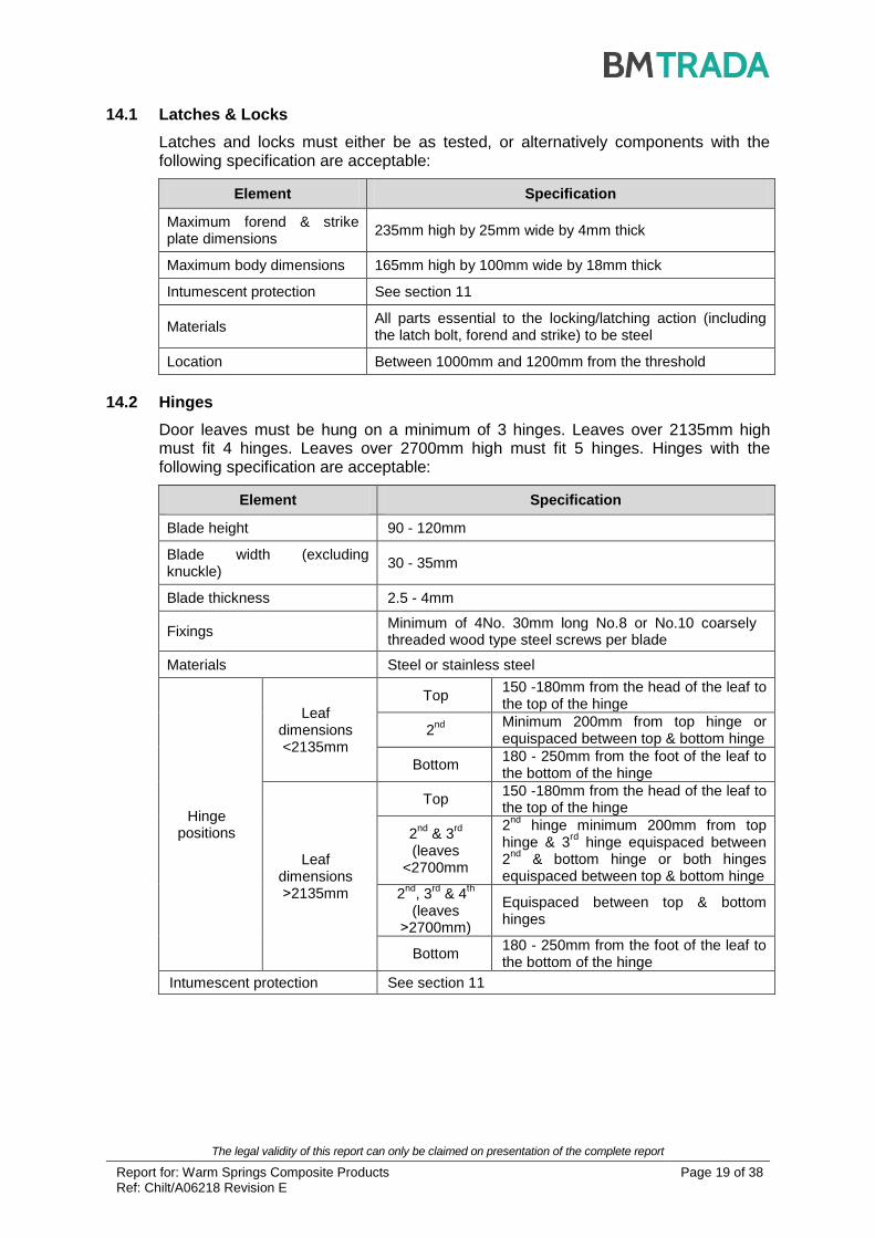
14.2 Hinges
Door leaves must be hung on a minimum of 3 hinges. Leaves over 2135mm high must fit 4 hinges. Leaves over 2700mm high must fit 5 hinges. Hinges with the following specification are acceptable:
Element Specification
Blade height 90 - 120mm
Blade width (excluding knuckle)
30 - 35mm
Blade thickness 2.5 - 4mm
Fixings Minimum of 4No. 30mm long No.8 or No.10 coarsely threaded wood type steel screws per blade
Materials Steel or stainless steel
Hinge positions
Leaf dimensions <2135mm
Top 150 -180mm from the head of the leaf to the top of the hinge
2nd
Minimum 200mm from top hinge or equispaced between top & bottom hinge
Bottom 180 - 250mm from the foot of the leaf to the bottom of the hinge
Leaf dimensions ˃2135mm
Top 150 -180mm from the head of the leaf to the top of the hinge
2nd
& 3rd
(leaves
<2700mm
2nd
hinge minimum 200mm from top hinge & 3
rd hinge equispaced between
2nd
& bottom hinge or both hinges equispaced between top & bottom hinge
2nd
, 3rd
& 4th
(leaves ˃2700mm)
Equispaced between top & bottom hinges
Bottom 180 - 250mm from the foot of the leaf to the bottom of the hinge
Intumescent protection See section 11

The legal validity of this report can only be claimed on presentation of the complete report
Report for: Warm Springs Composite Products Ref: Chilt/A06218 Revision E
Page 20 of 38
14.3 Automatic Closing
Automatic closing devices must either be as tested or components of equal specification that have demonstrated contribution to the required performance of this type of 60, 90 & 120 minute doorset design, when tested to BS 476: Part 22: 1987 or BS EN 1634-1.
Notes:
1. The top pivots to floor spring assemblies must be protected with 2mm thick WSCP Strip-seal or Interdens, on all edges of the mortices. Floor springs and pivots are only permitted for double acting door configurations at 60 minutes fire resistance.
2. Based on the results of RF12178, the Hoppe concealed overhead closer referenced AR7383 may be used for up to 120 minute fire resisting applications.
3. Alternative concealed overhead closers must have suitable fire resistance test evidence in timber or mineral composite doors to either BS 476: Part 22: 1987 or BS EN 1634-1, for the required integrity period.
14.4 Pull Handles
These may be surface-fixed or bolted through the door leaf provided that they are steel, the length is limited to 1000mm between fixing points, 1mm thick Interdens is wrapped around the full length of the stud and the hole through the leaf is tight to the stud.
14.5 Push Plates/Kick Plates/Generic Signage
Face-fixed hardware such as push plates, kick plates and metal signage (hotel door numbers, etc.) may be fitted to this doorset design provided that their fitting requires the removal of no part of the door leaf. These items of hardware must not amount to more than 20% of the door leaf area.
14.6 Panic Hardware
Panic hardware may be fitted provided that its installation does not require the removal of any timber from the leaf, stop or frame reveal and it does not interfere with the self-closing function of the doorset.
14.7 Signage
Plastic or metal fire safety signs may be glued or screwed to the face of door leaves. The signage must comply with BS 5499-5: 2002 according to whether the door is:
a. To be kept closed when not in use (Fire Door Keep Shut).
b. To be kept locked shut when not in use (Fire Door Keep Locked Shut).
c. Held open by an automatic release mechanism or free swing device (Automatic Fire Door Keep Clear).

The legal validity of this report can only be claimed on presentation of the complete report
Report for: Warm Springs Composite Products Ref: Chilt/A06218 Revision E
Page 21 of 38
14.8 Air Transfer Grilles
14.8.1 General
Air transfer grilles may be fitted providing the product has suitable test evidence to BS 476: Part 22: 1987 or BS EN 1634-1, that demonstrates a minimum 60, 90 or 120 minutes integrity performance, as applicable, when installed within a doorset of comparable thickness. Margins to the leaf edges will remain as detailed for glazing and the position of the unit will be dictated by the pressure regime tested in the proving evidence (normally below mid-height). The area occupied by the air transfer grille must not exceed 0.2m2 and must be deducted from the assessed glazed area, if both elements are fitted.
15 Door Gaps
For fire resistance applications, door gaps and alignment tolerances must fall within the following range:
Location Dimensions
Door edge gaps A minimum of 2mm and a maximum of 4mm
Alignment tolerances Leaves must not be proud of each other or from the door frame by more than 1mm
Threshold 10mm between bottom of leaf and top of floor covering
16 Structural Opening
The supporting construction must provide the required level of fire resistance designated for the doorset design and be a suitable medium to permit adequate fixity.
17 Fixings
The supporting construction must be capable of staying in place and intact for the full period of fire resistance required from the doorset. The frame jambs are to be fixed to the supporting construction using 5No. steel fixings (1No. fixing 200mm below the head, 1No. fixing 200mm above the threshold and 3No. fixings equally spaced in between). 2No. fixings are required in the frame head, set 500mm from the jambs. The fixings must be of the appropriate type for the supporting construction and must penetrate to a minimum depth of 50mm.

The legal validity of this report can only be claimed on presentation of the complete report
Report for: Warm Springs Composite Products Ref: Chilt/A06218 Revision E
Page 22 of 38
18 Sealing to Structural Opening
The door frame to structural opening gap must be protected using one of the following methods:
1. Gaps up to 10mm must be sealed on both sides with a 20mm depth of acrylic intumescent mastic that has demonstrated 90 or 120 minutes integrity to BS 476: Part 22: 1987 or BS EN 1634-1 (between masonry and timber or mineral composite). Joint must be fitted with 18mm thick architraves overlapping at least 15mm each side.
2. Gaps between 10 and 20mm must be tightly packed with mineral fibre and filled on both faces with a minimum of 20mm depth of intumescent mastic that has demonstrated 90 or 120 minutes integrity to BS 476: Part 22: 1987 or BS EN 1634-1 (between masonry and timber or mineral composite). The frame to structural opening gap must be covered with a minimum of 18mm thick hardwood architraves overlapping at least 15mm each side.
3. Proprietary gap filling product that has demonstrated 90 or 120 minutes integrity to BS 476: Part 22: 1987 or BS EN 1634-1 (between masonry and timber or mineral composite). The frame to structural opening gap must be covered with a minimum of 18mm thick hardwood architraves overlapping at least 15mm each side.
Notes:
Further to the options above it is permitted to install the door without architraves (or with architraves that do not meet the 15mm overlap requirement) providing the gap between the frame and the structural opening is suitably sealed with a proven linear gap seal that meets the following provisos:
1. The sealing medium has been tested at the required thickness and depth and has demonstrated 60, 90 or 120 minutes integrity, as appropriate, to BS 476: Part 22: 1987 or BS EN 1634-1 (between masonry and timber or mineral composite).
2. The sealing medium was tested without architrave or any other capping material.
Fire stopping product
Frame fixing Architrave
Architrave
Frame fixing
Mineral fibre infill for gaps up to 15mm
Acrylic intumescent mastic

The legal validity of this report can only be claimed on presentation of the complete report
Report for: Warm Springs Composite Products Ref: Chilt/A06218 Revision E
Page 23 of 38
19 Insulation
For fire resistance applications, insulation performance may be claimed for the WSCP doorset design meeting the following criteria:
Details Insulation Performance
Unglazed doorsets 90 minutes
20 Smoke Control
20.1 General
If the doorset design is required to provide a smoke control function to comply with Building Regulations, in the absence of a suitable pressurisation system, the doorset must meet one of the following criteria:
(a) have a leakage rate not exceeding 3m3/m/hour (head and jambs only) when tested at 25Pa under BS 476 Fire tests on building materials and structures, Section 31.1 - Methods for measuring smoke penetration through doorsets and shutter assemblies, Method of measurement under ambient temperature conditions; or
(b) meet the additional classification requirement of Sa when tested to BS EN 1634-3: 2004 - Fire resistance tests for door and shutter assemblies, Part 3 – Smoke control doors.
Smoke seals or combined intumescent/smoke seals that are fitted to the door to achieve the performance requirements specified above, must have been tested in accordance with the associated test method. Providing the smoke seals, any interruptions, door gaps, and the type/configuration of the doorset are consistent with the detail tested, the doorset will comply with current smoke control legislation under Approved Document B; and a suffix ‘S’ or ‘Sa’, as appropriate, may be added to the designation. Any other components installed where smoke leakage may occur must also be taken into account.
Note: The incorrect specification and fitting of smoke seals may impair the operation of a doorset and therefore compromise the fire resistance performance. Advice should be sought from the seal manufacturers regarding the correct specification and installation of smoke seals or combined smoke and intumescent seals.
20.2 Further Considerations
Note that there is other guidance available, including BS EN 9999-2008 - Code of practice for fire safety in the design, management and use of buildings, which may impose different or additional requirements, such as consideration of the gap between door leaf and threshold.
Responsibility for the appropriate smoke sealing specification and performance of the doors should be agreed between the relevant parties (i.e. specifier, manufacturer, contractor) prior to commencing manufacture and/or installation.
21 Conclusion
If the WSCP doorset design, constructed in accordance with the specifications documented in this Global Assessment, were to be tested in the appropriate configuration in accordance with BS 476: Part 22: 1987, it is our opinion that it would provide a minimum of 60, 90 or 120 minutes integrity, as appropriate.

The legal validity of this report can only be claimed on presentation of the complete report
Report for: Warm Springs Composite Products Ref: Chilt/A06218 Revision E
Page 24 of 38
22 Declaration by the Applicant
1) We the undersigned confirm that we have read and comply with obligations placed on us by FTSG Resolution No. 82: 2001.
2) We confirm that the component or element of structure, which is the subject of this assessment, has not to our knowledge been subjected to a fire test to the Standard against which this assessment is being made.
3) We agree to withdraw this assessment from circulation should the component or element of structure be the subject of a fire test to the Standard against which this assessment is being made.
4) We are not aware of any information that could adversely affect the conclusions of this assessment.
5) If we subsequently become aware of any such information, we agree to ask the assessing authority to withdraw the assessment.
Signed:
Name:
For and on behalf of: WARM SPRINGS COMPOSITE PRODUCTS
Jacob Coochise
Jacob Coochise

The legal validity of this report can only be claimed on presentation of the complete report
Report for: Warm Springs Composite Products Ref: Chilt/A06218 Revision E
Page 25 of 38
23 Limitations
The following limitations apply to this assessment:
1) This assessment addresses itself solely to the elements and subjects discussed and does not cover any other criteria. All other details not specifically referred to should remain as tested or assessed.
2) This assessment is issued on the basis of test data and information to hand at the time of issue. If contradictory evidence becomes available, BM TRADA reserves the right to withdraw the assessment unconditionally, but not retrospectively.
3) This assessment has been carried out in accordance with Fire Test Study Group Resolution No. 82: 2001.
4) Opinions and interpretations expressed herein are outside the scope of UKAS accreditation.
5) This assessment relates only to those aspects of design, materials and construction that influence the performance of the element(s) under fire resistance test conditions. It does not purport to be a complete specification ensuring fitness for purpose and long-term serviceability. It is the responsibility of the client to ensure that the element conforms to recognised good practice in all other respects and that, with the incorporation of the guidance given in this assessment, the element is suitable for its intended purpose.
24 Validity
1) The assessment is initially valid for five years from the date of issue, after which time it must be submitted to BM TRADA for re-appraisal.
2) This assessment report is not valid unless it incorporates the declaration given in Section 22, duly signed by the applicant.
Signature:
Name: J Godfrey A M Winning
Title: Product Assessor Senior Product Assessor

The legal validity of this report can only be claimed on presentation of the complete report
Report for: Warm Springs Composite Products Ref: Chilt/A06218 Revision E
Page 26 of 38
Appendix A
Performance Data
Primary Data
Report No. Configuration Leaf Size (mm) Test Standard Performance (mins)
RF03070 ULSADD 2100 x 900 x 55 BS 476: Pt 22: 1987 Integrity 122
1
Insulation 110
CFR1007071 LSADD 2265 x 1050 x 57 BS 476: Pt 22: 1987 Integrity 116
Insulation 95
CFR1007081
Right-hand specimen LSASD
2340 x 1075 x 57 BS 476: Pt 22: 1987
Integrity 91
Insulation 84
Left-hand specimen LSASD
Integrity 105
Insulation 93
CFR1009081 LSADD 2236 x 1036 x 57 BS 476: Pt 22: 1987 Integrity 131
Insulation 90
CFR1103111 ULSADD 2292 x 1068 x 57 BS 476: Pt 22: 1987 Integrity 151
Insulation 98
Note:
1. The tested specimen failed under the integrity criterion at 122 and 127 minutes due to continuous flaming from hinge positions. The specimen continued until 132 minutes at which time the facing ignited. Assessment has been made to use the later failure of 132 minutes integrity as the basis of leaf size calculations, by increasing the quantity of intumescent hinge protection by 100%, from 1mm thick Interdens to 2mm.

The legal validity of this report can only be claimed on presentation of the complete report
Report for: Warm Springs Composite Products Ref: Chilt/A06218 Revision E
Page 27 of 38
Supplementary Data
Report No. Configuration Leaf Size (mm) Test Standard Performance
(mins)
WF63295 (Glazing evidence)
ULSADD 2040 x 826 x 44 BS 476: Pt 22:
1987
Integrity 149
Insulation 70
WHI 495 PSV 1553 (Multi-piece stiles & rails)
Fixed sample 900 x 1000 x 44 UBC Standard
7-2 (1997)
90 (integrity) with 28 second hose
stream test
UL–100359573COQ-009 (Removal of intumescent gasket requirement around lock body
for 60 & 90 minute applications)
LSASD 2440 x 1220 x
44
UL 10(c) (2009) &
CAN/ULCS104 – 10
90 (integrity) with 48 second hose
stream
IF12047 (Norglaze Universal 90)
ULSASD sample
1040 x 996 x 58 Principles of BS
476: Pt 20: 1987
Integrity: 106
RF12178 (Hardwood door frames up to 120 minutes & Hoppe UK Ltd.
hardware)
A: ULSASD 2036 x 916 x 57 BS EN 1634-1 & BS EN 1363-
1
Integrity 121
Insulation 71
B: ULSASD 2040 x 918 x 57 Integrity 148
Insulation 82
CFR1504141 (Cooke Bros. Ltd. & Hoppe UK
Ltd. hardware)
ULSASD 2284 x 1068 x
58 BS EN 1634-1
Integrity 117
Insulation 76
CFR14103111
(Zoo Architectural and Turentek Architectural hardware)
ULSADD 2289 x
1068/1069 x 58 BS EN 1634-1
Integrity 200
Insulation 91
Note:
1. The perimeter intumescent specification tested in CFR1410311 has been used to justify the perimeter intumescent specification detailed in section 11 of this assessment, for all applications and configurations.

The legal validity of this report can only be claimed on presentation of the complete report
Report for: Warm Springs Composite Products Ref: Chilt/A06218 Revision E
Page 28 of 38
Appendix B
Lorient Tested Glazing System
25
22
2mm thick Palusol 100P sheet self adhered to perimeter of aperture for glazing for full width of leaf
1.6mm thick (16 gauge) ‘Z’ section mild steel beads
Lorient System 90+ glazing channel
Assessed glass
90o angle for
steel bead
Inter screw sleeve bolt – 37mm long x 4.9mm diameter sleeve with 43mm long x 3.8mm diameter screw bolt. The bolts are to be fitted at 125mm centres around the glazed aperture and at 45mm in from outside corners

The legal validity of this report can only be claimed on presentation of the complete report
Report for: Warm Springs Composite Products Ref: Chilt/A06218 Revision E
Page 29 of 38
Appendix C
Tectonite Door Frame Constructions
Tectonite (2-4mm hardwood or MDF veneer)
Tectonite (hardwood composite)
2 or 4mm hardwood or MDF veneer may be applied on all faces of the door frame
94mm (w) x 43mm (t) section of Tectonite
12mm deep planted or rebated stop (hardwood or Tectonite). The stop may be fixed by screwing through the rear of the frame. The fixing must penetrate the stop to a depth of 8mm
18mm thick architrave
72mm (d) x 43mm (w) Tectonite
4mm thick hardwood facing rebated to accommodate intumescent seals
12mm planted stop (hardwood)
Two layers of 20x47 hardwood or one layer 40x47 hardwood glued to Tectonite frame core

The legal validity of this report can only be claimed on presentation of the complete report
Report for: Warm Springs Composite Products Ref: Chilt/A06218 Revision E
Page 30 of 38
Warm Springs Composite Products T-Stop Detail (dimensions in mm)
Warm Springs Composite Products Frame Width Extension Detail
38
12
25
3
T-Stop with a 25mm (w) x 3mm (d) tongue to locate into a groove on the face of the frame. The stop is machined to have a slightly narrower end than the groove in the frame to give a snug fit. The stop is then mechanically fixed using pins or screws. The T-Stop may be constructed of hardwood or Tectonite meeting the specification in section 8 for 60, 90 or 120 minutes fire resistance
Tongue and groove joint

The legal validity of this report can only be claimed on presentation of the complete report
Report for: Warm Springs Composite Products Ref: Chilt/A06218 Revision E
Page 31 of 38
Appendix D
Revisions
Rev. BM TRADA Ref. Date Description
A Chilt/A10229 31/01/11 Technical review, update of assessment format and revalidation for a further 5 years including test data CFR1007071, CFR1007081 and CFR1009081.
B Chilt/A11145 18/07/11
Inclusion of test data CFR1103111 to rationalise the design options, allow for variable stile and rail widths, permit hotmelt adhesive for lipping door edges at all ratings and allow for additional leaf sizes at 60, 90 and 120 minutes in latched and unlatched configurations.
C Chilt/A12092 11/05/12
Removal of intumescent gasket requirement around the lock body for 60 and 90 minute applications (Design A and Design B) based on UL test evidence referenced 100359573COQ-009; concealed over head closers for 60 minute applications; air transfer grilles; increase in decorative groove scope to allow for different grooving patterns - limitation to be presented as a percentage of material removal from the outer face; alteration to construction to allow for enhanced acoustic performance; to include: 6mm MDF outer faces (all leaf dimensions permitted at 60 and 90 minutes fire resistance, 2292mm (h) x 1068mm (w) at 120 minutes fire resistance); NOR810s drop seal; NOR710 around perimeter of leaf; adjustment to leaf edge – stiles 25mm to 43mm, rails 51mm to 102mm (Design B only, all ratings); architrave and sealing to structural opening options (option for no architrave subject to suitably tested linear gap seal); door frame options – minimum section of Tectonite to be stated as 94mm (w) x 43mm (t) to allow for sizing during manufacture; veneer options for door frame to include hardwood and MDF; inclusion of drilling pilot holes in Tectonite for frame construction and fitting of hardware; repositioning the second hinge to within 100mm of the top hinge; inclusion of Norglaze Universal 90 glazing system.
D Chilt/A12092 03/08/12 Inclusion of metal signage, additional intumescent specification for WSCP Design B and alternative planted stop material.
E CNA/F15171 16/10/15
Inclusion of test data from RF12178, CFR1504141 & CFR1410311 covering hardwood door frames up to 120 minutes, a range of Hoppe UK Ltd, Zoo Architectural Hardware Ltd, Turentek Architectural Hardware Ltd. & Cooke Brothers Ltd. hardware; removal of all references to Door Design A and removal of option 2 from the intumescent options for the remaining doorset design.
The legal validity of this report can only be claimed on presentation of the complete report
Report for: Warm Springs Composite Products Ref: Chilt/A06218 Revision E
Page 32 of 38
Appendix E
Data Sheets for:
Warm Springs Composite Products
60, 90 & 120 Minute Fire Resisting Doorsets

The legal validity of this report can only be claimed on presentation of the complete report
Report for: Warm Springs Composite Products Ref: Chilt/A06218 Revision E
Page 33 of 38
2200
2300
2400
2500
2600
2700
2800
2900
3000
3100
3200
3300
3400
3500
3600
1000 1100 1200 1300 1400 1500 1600 1700
He
igh
t (m
m)
Width (mm)
Maximum Door Leaf Size
LSASD ULSASD & DASD
Warm Springs Composite Products – 60 Minutes Fire Resistance
Latched & Unlatched, Single & Double Acting, Single Doorsets
Leaf Sizes
Configuration Height (mm) Width (mm)
LSASD From:
To:
2292 x 1677
3588 x 1068
ULSASD & DASD
From: To:
2292 x 1652
3538 x 1068
Maximum Overpanel Height (mm) Transomed 500
Glazing Maximum Glazed Area See section 7 for details
Approved Systems See section 7 and Appendix B
Frame Specification
Material Tectonite Hardwood
Min. Density (kg/m3) See section 8 See section 8
Min. Section (mm) See section 8 See section 8
INTUMESCENT MATERIALS: WSCP
HEAD: See section 11.
JAMBS: See section 11.
HARDWARE PROTECTION: See section 11.
The legal validity of this report can only be claimed on presentation of the complete report
Report for: Warm Springs Composite Products Ref: Chilt/A06218 Revision E
Page 34 of 38
2200
2300
2400
2500
2600
2700
2800
2900
3000
3100
3200
3300
3400
3500
1000 1100 1200 1300 1400 1500 1600
He
igh
t (m
m)
Width (mm)
Maximum Door Leaf Size
LSADD ULSADD & DADD
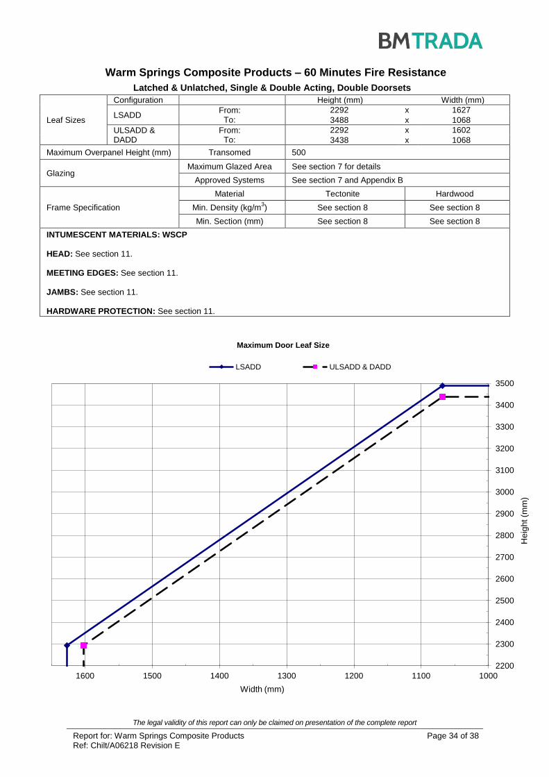
Warm Springs Composite Products – 60 Minutes Fire Resistance
Latched & Unlatched, Single & Double Acting, Double Doorsets
Leaf Sizes
Configuration Height (mm) Width (mm)
LSADD From:
To:
2292 x 1627
3488 x 1068
ULSADD & DADD
From: To:
2292 x 1602
3438 x 1068
Maximum Overpanel Height (mm) Transomed 500
Glazing Maximum Glazed Area See section 7 for details
Approved Systems See section 7 and Appendix B
Frame Specification
Material Tectonite Hardwood
Min. Density (kg/m3) See section 8 See section 8
Min. Section (mm) See section 8 See section 8
INTUMESCENT MATERIALS: WSCP
HEAD: See section 11.
MEETING EDGES: See section 11.
JAMBS: See section 11.
HARDWARE PROTECTION: See section 11.

The legal validity of this report can only be claimed on presentation of the complete report
Report for: Warm Springs Composite Products Ref: Chilt/A06218 Revision E
Page 35 of 38
2200
2300
2400
2500
2600
2700
2800
2900
3000
3100
3200
1000 1100 1200 1300 1400 1500
He
igh
t (m
m)
Width (mm)
Maximum Door Leaf Size
LSASD ULSASD
Warm Springs Composite Products – 90 Minutes Fire Resistance
Latched & Unlatched, Single Acting, Single Doorsets
Leaf Sizes
Configuration Height (mm) Width (mm)
LSASD From:
To:
2292 x 1500
3209 x 1068
ULSASD From:
To:
2292 x 1475
3159 x 1068
Maximum Overpanel Height (mm) Transomed 500
Glazing Maximum Glazed Area See section 7 for details
Approved Systems See section 7 and Appendix B
Frame Specification
Material Tectonite Hardwood
Min. Density (kg/m3) See section 8 See section 8
Min. Section (mm) See section 8 See section 8
INTUMESCENT MATERIALS: WSCP
HEAD: See section 11.
JAMBS: See section 11.
HARDWARE PROTECTION: See section 11.

The legal validity of this report can only be claimed on presentation of the complete report
Report for: Warm Springs Composite Products Ref: Chilt/A06218 Revision E
Page 36 of 38
2200
2300
2400
2500
2600
2700
2800
2900
3000
3100
1000 1100 1200 1300 1400 1500
He
igh
t (m
m)
Width (mm)
Maximum Door Leaf Size
LSADD ULSADD
Warm Springs Composite Products – 90 Minutes Fire Resistance
Latched & Unlatched, Single Acting, Double Doorsets
Leaf Sizes
Configuration Height (mm) Width (mm)
LSADD From:
To:
2292 x 1450
3109 x 1068
ULSADD From:
To:
2292 x 1425
3059 x 1068
Maximum Overpanel Height (mm) Transomed 500
Glazing Maximum Glazed Area See section 7 for details
Approved Systems See section 7 and Appendix B
Frame Specification
Material Tectonite Hardwood
Min. Density (kg/m3) See section 8 See section 8
Min. Section (mm) See section 8 See section 8
INTUMESCENT MATERIALS: WSCP
HEAD: See section 11.
MEETING EDGES: See section 11.
JAMBS: See section 11.
HARDWARE PROTECTION: See section 11.

The legal validity of this report can only be claimed on presentation of the complete report
Report for: Warm Springs Composite Products Ref: Chilt/A06218 Revision E
Page 37 of 38
2200
2300
2400
2500
2600
2700
2800
2900
3000
3100
1050 1100 1150 1200 1250 1300 1350 1400 1450
He
igh
t (m
m)
Width (mm)
Maximum Door Leaf Size
LSASD & ULSASD
Warm Springs Composite Products – 120 Minutes Fire Resistance
Latched & Unlatched, Single Acting, Single Doorsets
Leaf Sizes
Configuration Height (mm) Width (mm)
LSASD & ULSASD
From: To:
2289 x 1421
3048 x 1068
Maximum Overpanel Height (mm) Transomed 500
Glazing Maximum Glazed Area See section 7 for details
Approved Systems See section 7 and Appendix B
Frame Specification
Material Tectonite Hardwood
Min. Density (kg/m3) See section 8 See section 8
Min. Section (mm) See section 8 See section 8
INTUMESCENT MATERIALS: WSCP
HEAD: See section 11.
JAMBS: See section 11.
HARDWARE PROTECTION: See section 11.

The legal validity of this report can only be claimed on presentation of the complete report
Report for: Warm Springs Composite Products Ref: Chilt/A06218 Revision E
Page 38 of 38
2200
2300
2400
2500
2600
2700
2800
2900
3000
3100
1050 1100 1150 1200 1250 1300 1350 1400 1450
He
igh
t (m
m)
Width (mm)
Maximum Door Leaf Size
LSADD & ULSADD
Warm Springs Composite Products – 120 Minutes Fire Resistance
Latched & Unlatched, Single Acting, Double Doorsets
Leaf Sizes
Configuration Height (mm) Width (mm)
LSADD & ULSADD
From: To:
2289 x 1421
3048 x 1068
Maximum Overpanel Height (mm) Transomed 500
Glazing Maximum Glazed Area See section 7 for details
Approved Systems See section 7 and Appendix B
Frame Specification
Material Tectonite Hardwood
Min. Density (kg/m3) See section 8 See section 8
Min. Section (mm) See section 8 See section 8
INTUMESCENT MATERIALS: WSCP
HEAD: See section 11.
MEETING EDGES: See section 11.
JAMBS: See section 11.
HARDWARE PROTECTION: See section 11.

REGISTERED IN ENGLAND NO. 3125010