global finishing solutions accessories - dudley … · filtration media made for paint spray...
TRANSCRIPT

1 www.globalfinishing.com www.globalfinishing.com
spray booth Parts & components
Quality • Durability • service
®G L O B A L F I N I S H I N G S O L U T I O N S
Accessories
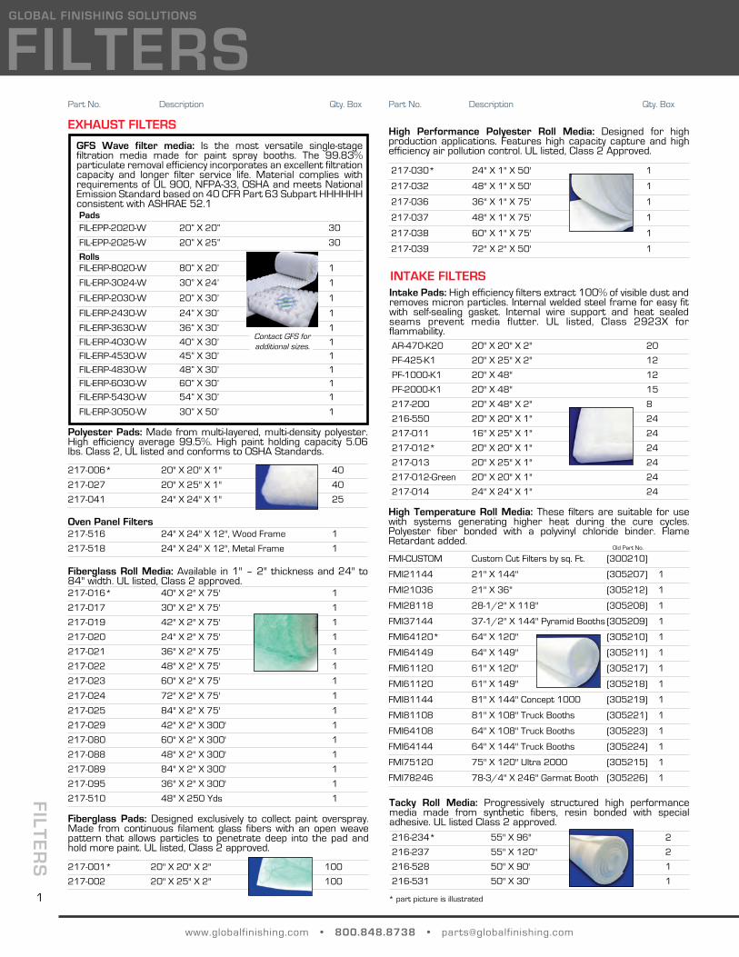
GFS Wave filter media: Is the most versatile single-stagefiltration media made for paint spray booths. The 99.83%particulate removal efficiency incorporates an excellent filtrationcapacity and longer filter service life. Material complies withrequirements of UL 900, NFPA-33, OSHA and meets NationalEmission Standard based on 40 CFR Part 63 Subpart HHHHHHconsistent with ASHRAE 52.1PadsFIL-EPP-2020-W 20” X 20” 30
FIL-EPP-2025-W 20” X 25” 30
RollsFIL-ERP-8020-W 80” X 20’ 1
FIL-ERP-3024-W 30” X 24’ 1
FIL-ERP-2030-W 20” X 30’ 1
FIL-ERP-2430-W 24” X 30’ 1
FIL-ERP-3630-W 36” X 30’ 1
FIL-ERP-4030-W 40” X 30’ 1
FIL-ERP-4530-W 45” X 30’ 1
FIL-ERP-4830-W 48” X 30’ 1
FIL-ERP-6030-W 60” X 30’ 1
FIL-ERP-5430-W 54” X 30’ 1
FIL-ERP-3050-W 30” X 50’ 1
Tacky Roll Media: Progressively structured high performancemedia made from synthetic fibers, resin bonded with specialadhesive. UL listed Class 2 approved.216-234* 55" X 96" 2
216-237 55" X 120" 2
216-528 50" X 90' 1
216-531 50" X 30' 1
Fiberglass Pads: Designed exclusively to collect paint overspray.Made from continuous filament glass fibers with an open weavepattern that allows particles to penetrate deep into the pad andhold more paint. UL listed, Class 2 approved.
217-001* 20" X 20" X 2" 100
217-002 20" X 25" X 2" 100
Polyester Pads: Made from multi-layered, multi-density polyester.High efficiency average 99.5%. High paint holding capacity 5.06lbs. Class 2, UL listed and conforms to OSHA Standards.
217-006* 20" X 20" X 1" 40
217-027 20" X 25" X 1" 40
217-041 24" X 24" X 1" 25
Oven Panel Filters217-516 24" X 24" X 12", Wood Frame 1
217-518 24" X 24" X 12", Metal Frame 1
Fiberglass Roll Media: Available in 1" – 2" thickness and 24" to84" width. UL listed, Class 2 approved. 217-016* 40" X 2" X 75' 1
217-017 30" X 2" X 75' 1
217-019 42" X 2" X 75' 1
217-020 24" X 2" X 75' 1
217-021 36" X 2" X 75' 1
217-022 48" X 2" X 75' 1
217-023 60" X 2" X 75' 1
217-024 72" X 2" X 75' 1
217-025 84" X 2" X 75' 1
217-029 42" X 2" X 300' 1
217-080 60" X 2" X 300' 1
217-088 48" X 2" X 300' 1
217-089 84" X 2" X 300' 1
217-095 36" X 2" X 300' 1
217-510 48" X 250 Yds 1
High Performance Polyester Roll Media: Designed for highproduction applications. Features high capacity capture and highefficiency air pollution control. UL listed, Class 2 Approved.
217-030* 24" X 1" X 50' 1
217-032 48" X 1" X 50' 1
217-036 36" X 1" X 75' 1
217-037 48" X 1" X 75' 1
217-038 60" X 1" X 75' 1
217-039 72" X 2" X 50' 1
FILT
ER
S
www.globalfinishing.com • 800.848.8738 • [email protected]
GLOBAL FINISHING SOLUTIONS
INTAKE FILTERSIntake Pads: High efficiency filters extract 100% of visible dust andremoves micron particles. Internal welded steel frame for easy fitwith self-sealing gasket. Internal wire support and heat sealedseams prevent media flutter. UL listed, Class 2923X forflammability.AR-470-K20 20" X 20" X 2" 20
PF-425-K1 20" X 25" X 2" 12
PF-1000-K1 20" X 48" 12
PF-2000-K1 20" X 48" 15
217-200 20" X 48" X 2" 8
216-550 20" X 20" X 1" 24
217-011 16" X 25" X 1" 24
217-012* 20" X 20" X 1" 24
217-013 20" X 25" X 1" 24
217-012-Green 20" X 20" X 1" 24
217-014 24" X 24" X 1" 24
EXHAUST FILTERS
Part No. Description Qty. Box Part No. Description Qty. Box
* part picture is illustrated
Contact GFS foradditional sizes.
High Temperature Roll Media: These filters are suitable for usewith systems generating higher heat during the cure cycles.Polyester fiber bonded with a polyvinyl chloride binder. FlameRetardant added.
FMI-CUSTOM Custom Cut Filters by sq. Ft. (300210)
FMI21144 21" X 144" (305207) 1
FMI21036 21" X 36" (305212) 1
FMI28118 28-1/2" X 118" (305208) 1
FMI37144 37-1/2" X 144" Pyramid Booths (305209) 1
FMI64120* 64" X 120" (305210) 1
FMI64149 64" X 149" (305211) 1
FMI61120 61" X 120" (305217) 1
FMI61120 61" X 149" (305218) 1
FMI81144 81" X 144" Concept 1000 (305219) 1
FMI81108 81" X 108" Truck Booths (305221) 1
FMI64108 64" X 108" Truck Booths (305223) 1
FMI64144 64" X 144" Truck Booths (305224) 1
FMI75120 75" X 120" Ultra 2000 (305215) 1
FMI78246 78-3/4" X 246" Garmat Booth (305226) 1
FILTERS
Old Part No.
1

FILT
ER
S
www.globalfinishing.com • 800.848.8738 • [email protected]
GLOBAL FINISHING SOLUTIONS
Part No. Description Qty. Box
2- and 3- STAGE FILTRATIONThree-stage system specifically designed for the collection ofaerospace chromate coating overspray,virtually eliminating dangerous chromiumemissions. Exceeds E.P.A Method 319: TestMethod 319 for Aerospace Manufacturingand Reworking (NESHAP).
Stage 1 - Roll Media, Multi-LayeredPolyester Media. The air-entry side isconstructed of a mixture of lofted denierfiber. The air-leaving side is comprised of amixture of heavily needled media to densify. Weighs 1.2oz persquare foot.
216-502 36" X 50' CPA 1
216-503 45" X 50' CPA 1
Stage 2 - MEPT panel, is constructed of two different layers oftackified polyester media, sealed together so the tackified layers ofeach media touch in the center. The air-entry layer is constructedof multi-layered, multi-density polyester with heavy, non-migratingtackifier on the air-leaving side. The air-leaving media is a heavilyneedled polyester, up to 1/4" thick, tackified on the air-entry sidewith a weight of 0.42oz per square foot.
216-501 20" X 20" X 1" MEPT 24
216-5011 20" X 20" CPA 24
216-517 24" X 24" X 1" MEPT 24
Stage 3 - 6-pocket bag filter, is constructed of a composite of pre-filter, melt blown and spun bound polyester fibers. The pockets aresewn together on the perimeter with two heat seals, forming threeair channels in each bag pocket. The bag pockets on the metalsupport are inserted into a galvanized metal header. The galvanizedheader contains an acceptable sealing agent inside of each headerto eliminate the possibility of paint bypass within the filter.
216-500 20" X 20" X 15", 2 Pocket 1
216-505 20" X 20" X 12", 6 Pocket 1
216-516 24" X 24" X 12", 6 Pocket 1
Filters to clean air entering air replacement units, fabric andcleanables.216-120* 24" X 24" X 2" 1
216-121 20" X 20" X 1" 1
216-122 16" X 25" X 1" 1
216-124 20" X 25" X 1" 1
216-125 20" X 20" X 2" 1
216-126 16" X 25" X 2" 1
216-128 20" X 25" X 2" 1
216-129 12" X 12" X 1" 1
AR-9022-K12* 20" X 20" 12
AR-9026-K12 20" X 25" 12
AR-9027-K12 20" X 16" 12
FS-2072-K6 20" X 72", Burner Filter 6
PF-500-K6 20" X 25"X 10", Cube 6
PF-879-K2 25" X 75" 2
POWDER & DUST FILTERS
Bag Filters: Pocketed filter, individual pocket edges and internaldividing bars are heat sealed for no stitch holes. The exceptionallyhigh dust holding capacity provides long life.
216-504 20" X 20" X 15", 2 Pocket 1
216-505* 20" X 20" X 12", 6 Pocket 1
Pad: Medium efficiency pleated panel filter. Contains up to 16pleats per linear foot. Radial pleat construction for minimumpressure. Available in UL listed, Class 2 or 1, in 4", 2" and 1" depths.Nonwoven cotton/ synthetic blend media.
216-003 20" X 20" X 4" 5
216-011* 20" X 20" X 2" 1
216-057 20" X 20" X 12" 1
Cartridge: For Powder Recovery booths and safe air dustcollection systems.
216-202 26" X 12 3/4" 1
216-203* 26" X 12 3/4" 1
216-204* 26" X 12 3/4" 1
PAINT ARRESTOR - PaperPaper Mesh: The mesh filters are comprised of numerous layersof UL listed, Class 2 approved kraft media.
216-088* 20" X 20" X 1" 60
216-089 20" X 25" X 1" 70
216-095 42" X 2" X 30' 1
216-113 42" X 1-1/2" X 30' 1
Paper Mesh Polyester Backing: These filters are highly efficientand are known for their high dust holding capacity. They areconstructed of seven layer expanded paper with a white polyesterbacking.
EF-2020-K40 20" X 20" X 2" 40
EF-2025-K40* 20" X 25" Pad 40
EF-3125-K2 31" X 25' Roll 2
EF-4253-K1 42" X 53' Roll 1
Pleated Cardboard: The unique collapsible pleated filter with roundholes captures paint particles outside the air stream in the holdingpockets.
PEF-330-K1* 3' X 30' 1
Part No. Description Qty. Box
* part picture is illustrated
AUTOMOTIVEFinal filters on automotive lines.33033 24" X 24" X 2" Prep Cartridge 4
405213 23 1/4" X 47" X 9", 6 Pocket Green 4
405214 23 1/2" X 47" Framed 5 Pocket 4
405216 19 1/4" X 37" X 4" Cartridge Hi-Cap. 4
405217 19 3/4" X 37" X 4" Cartridge Hi-Cap. 4
405219 19 1/2" X 36 3/4", 6 Pocket Hi- Cap. 4
FM2336 23 1/2" X 35 5/8", 4 Pocket SpaceSaver 4
Fiberglass Roll Media.
500200 20" X 2.5" X 300' 1
500250 25" X 2.5" X 300' 1
500300 30" X 2.5" X 300' 1
500360 36" X 2.5" X 300' 1
500400 40.5" X 2.5" X 300' 1Contact Parts & Filters Sales for other types
of filters that are available. 2

DO
OR
S
www.globalfinishing.com • 800.848.8738 • [email protected]
GLOBAL FINISHING SOLUTIONS
DOORS
A
B
A
B
A
B
A
B
Solid Swing Door Filtered Swing Door
PRODUCT DOORSProduct doors are constructed of tubular frames and sheet metal,and are factory painted. Filters, door handles, door safety latchesand foam tape are included.
> Solid Doors are used with pressurized input plenums toenclose open face paint booths in pressurized applications.Door size will be 2 feet shorter than interior booth height and4 feet narrower than interior booth width.
> Filter Doors allow product entry and exit while filtering theinput air. These doors are used with non-pressurized booths.They are attached directly to the front of the booth and addminimal depth.
PERSONNEL DOORS3' X 7' Universal Personnel AccessDoors are constructed of 18-gaugegalvanized sheet steel. The doorcan be located on either side ofbooth to meet user requirements.18" x 24" observation windows areavailable.
Door can be installed for either rightor left hand swing, includesinstallation kit. Also available in pre-coat white.
OBSERVATION WINDOWSDesigned for applications with booth panels and for use with solidproduct doors. An attractive option for personnel safety. Cleartempered glass for safe and unobstructed viewing of paintingoperations.
Personnel DoorsPart No. Description
MDUG-36084 36" w X 84" h, Galvanized
MDUG-36084-OSQ36" w X 84" h, with Observation Window,Galvanized
MDUW-36084 36" w X 84" h, pre-coat White
MDUW-36084-OSQ36" w X 84" h, with Observation Window, pre-coat White
Notes: > Indicate Width (A) and Height (B) when ordering.> Tri-Fold/Multi-Wing Doors are also available, please consult GFS.
Observation Windows
Part No. Description
Personnel Door Kit includes Tempered Glass, Weather Stripping, WindowFrame, Window Template, and Instructions
WK-1824-MANDOOR 18" X 24", Galvanized
WK-1824-MANDOOR-WH 18" X 24", Pre-coat White
Panel Kit includes Tempered Glass, Weather Stripping and WindowFrame.
WK-1824 18" X 24"
WK-1848 18" X 48"
Solid Bi-Fold Door Filtered Bi-Fold Door
Observation Window Optional Sizes
Part No. Dimension
230-001 18" x 24"
230-197 18" x 48"
230-196 24" x 30"
230-195 24" x 48"
230-235 30" X 30"
230--064 30" X 48"
GLS-25T-18024-SQ 18" x 24" Sq. Corners
Product Doors
FaceMount
FlangeMount Width Height Galvanized White
Solid Swing Door IPDS PDS2
A B G WSolid Bi-Fold Door N/A PDS4
Filter Swing Door IPDF PDF2
Filter Bi-Fold Door N/A PDF4
ROLL-UP DOORSRoll-up doors are manufactured per GFS'specifications. Finished product is delivereddirect to the jobsite by the manufacturer tobe installed, adjusted and serviced by trainedfactory personnel.
Product: Available in galvanized stainlesssteel and aluminum. Finished range from 21standard colors to 172 premium colors orcolor matched to customer specifications aswell as colored anodized aluminum.
3

Door Seals
Part No. Description
SS-0074815' x 7" x 1/8" Black Rubber S.S. Booths
SS-0074912-1/2' x 3/4" x 1-1/2"Foam Tape - S.S. Booths Grey
SS-00777.5 X .5 X 25' Roll (LT FXT)Foam Tape
SS-9688V Seal 108" Long w/Retainer Strip
SS-987434' x 1/4" x 3/8" Black Foam TapeSingle Skin Booths
Single Skin Booths
SS-00748 (3)SS-00749 (3)SS-9874 (1)
1960 - 1990'sSolid Backs
FlexbuiltSemi-Downdraft
Concept IIConcept II Cure
Old "Concept Booths"Old "XVS" series
Crossdrafts
SS-00748 (6)SS-00749 (6)SS-9874 (1)
Drive Thru's
SS-00748 (2)SS-00749 (3)SS-9688 (1)SS-9874 (1)
1990's - PresentSolid BacksThese seals come in kit-KDS
SS-00748 (4)SS-00749 (6)SS-9688 (1)SS-9874 (1)
Drive Thru's
Ovens
248-035Tadpole Gasket, .50 Bulb, 1.0" Tail
Insulated BoothsFor use on booth panels approximately 2" thick, constructed of two sheetsof metal with insulation in between.
39056
3/4" x 3/4"Black rubber hollow strip,Frontal and access doors,Blowtherm /Concept Cure
R8550
3/4" x 3/4"Black rubber hollow strip,Frontal and access doors.GFS Booths
DGK-2000
3/4" x 3/4" x 25'Black foam tape. Contains 4rolls to refoam a 3 doorfrontal and 1 access door.Older DeVilbiss, System2000's, Expert Performer &Professional
www.globalfinishing.com • 800.848.8738 • [email protected]
GLOBAL FINISHING SOLUTIONS
DO
OR
S
Door Seals
Part No. Description
248-003.50 x .25 Closed CellSeal Tape
248-004.50 x .50 Closed CellSeal Tape
248-0073/16" x 5/8" W, 30' RollTape Butyl
248-011.125 x 3.0 WRubber Strip
248-012.125 x 4.0 WRubber Strip
248-013.125 x 5.0 WRubber Strip
248-014.125 x 6.0 WRubber Strip
248-021.125 x 8.0 WRubber Strip
248-023.125 x 10.0 WRubber Strip
248-082P Seal - EPDMSeal Tape
248-0871/4" x 3/4" Wide Open CellTape Adhesive
248-0891/8" Thick x 5" WSilicone Rubber
29-148012' L x 3" W x 1/8"Door Wiper Seal - Binks
29-14818' L x 2" x 11/16"Bi-Fold Seal Binks
29-14829' L x 2" x 1 1/4" "T" Seal Binks
29-1484 30' Length - Binks "U" Seal
KDSSeal Kit Bi/Tri Fold DeVilbiss only
4

ELE
CT
RIC
AL
www.globalfinishing.com • 800.848.8738 • [email protected]
ELECTRICALGLOBAL FINISHING SOLUTIONS
3-Way Safety Air ValvePart No. Description
242-124 3/4" Ports
3 Port/2-Position air valve preventsspraying with air assist systems when boothexhaust is off. Compressed air between valveand spray equipment is vented out whenexhaust is shut off. 120 Volt coil.
242-019 1/2" Ports
3 Port/2-Position air valve preventsspraying with air assist systems when boothexhaust is off. Compressed air between valveand spray equipment is vented out whenexhaust is shut off. 120 Volt coil.
242-028 For LOGIC controls - Automotive
36267 Economy Spray Gun interlock - Automotive
Limit SwitchesElectronically operated switches shutdown the painting operations whenbooth doors are opened. Time delay relay allows access to the boothwithout stopping operations. Interior shutdown switch stops paintingoperations from inside.
242-012CL 1, Div. 1Explosion ProofSwitch
242-014CL 1, Div. 2 Standard Switch
Air Proving Switch242-004 Automatic pressure switch, measures air
pressure at the exhaust chamber.Recommended for use with Safety Air Valve.
Light Switches650-001 Explosion Proof
On/Off switch used in hazardous locations,front operated, and one pole will handle1400W- AC (Used with lights).
650-002 General Purpose
On/Off switch used in non-hazardouslocations and will handle 1400W- AC (Usedwith lights).
Start/Stop Part No. Description
127-221 Explosion Proof
Heavy-duty, start/stop, front operatedbutton can be mounted directly on booth(Used with motor starters).
127-219 General Purpose
NEMA Type 1 start/stop with N.O.-N.C.contacts. Must be mounted in non-hazardous location (Used with motorstarters).
650-003 Pneumatic
This system activates a pneumatic- electricinterface, start/stop switch that turns theexhaust fan on/off. A non-sparkingpneumatic switch is located inside the spraybooth allowing the operator to enter andleave the booth with the exhaust fan turnedoff – avoiding dirty unfiltered air fromentering the paint area.
Booth Gauges242-001 Manometer/Draft Gauge
Indicates when paint arrestors or air intakefilters have become sufficiently loaded andneed replacement. Meets codecompliance. Included with all exhaustchambers and booths.
GA-9706 Magnahelic Gauge - Automotive
Indicates when the booth cabin is balancedand ready for spraying, gauge must becalibrated prior to use.
Safety Shut-Down System automatically turns off compressed air to the spray gun when paintaccumulation in the exhaust filters reaches a preset load point thatprevents proper airflow through the booth. Complies with fire, health andinsurance code requirements.
600-003 Standard System
600-004 Standard System w/Audible Alarm
600-005 Explosion Proof System
600-035 Gun Hanger
Explosion proof, Class 1, Division 1.Automatic start-up of ventilation when thespray gun is lifted from the hanger, uponreturn of spray gun to hanger, the exhaustsystem purges and shuts down.
5

LIG
HT
ING
www.globalfinishing.com • 800.848.8738 • [email protected]
GLOBAL FINISHING SOLUTIONS
Corner Lighting
Part No. Tube Length Volt/Watt
LAC12-4 4 4' 120-277V / 32W
LAC12-6 6 4' 120-277V / 32W
Inside Access Lighting
Part No. Tube Length Lamp Size/Volt/Watt
230-306 2 4' T8 / 120V / 32W
230-308 4 4' T8 / 120V / 32W
230-501 4 4' T8 / 120-277V / 32W
230-400 2 3' T8 / 120V /25W
230-405 4 3' T8 / 120V / 25W
INCANDESCENT LIGHTINGFLUORESCENT LIGHTING
EXPLOSION PROOF LIGHTING> U.L. listed 844 hazardous location Class I Division 1, Groups C &
D. U.L. listed 595 outdoor type (salt water). U.L. paint spray boothapproved.
> CSA certified for hazardouslocations, Class I, Division 1,Groups C & D.
> 60 HZ, 40 or 60 Watt HOavailable. Multiple voltages.
Incandescent Lighting
Part No. Style Lamp Size/Watt
600-001 Ceiling Mount w/Dome 150/300W
600-002 Wall Mount w/ Dome 150/300W
600-006 Ceiling Mount w/Angle 150/300W
600-001
600-002
600-006
230-405
Rear Access Lighting
Part No. Tube Length Lamp Size/Volt/Watt
230-183 4 4' T12 / 110V /60W
230-551 4 4' 120V/32W
230-183
Explosion Proof Lighting
Part No. Tube Length Lamp Size/Watt
230-160 2 4' 120V/60W
230-162 4 4' 120V/40W
230-180 4 4' 277V/40W
230-181 4 4' 120V/60W
> Meets state and local safety specifications for Class I, Division 1, Hazardous location.
> Angle fixtures can be supported for mounting at face of booth withfixture bracket Part # 414-004
> Recommended for use in paint supply mixing and storage areas.
> GS Manufactured
> E.T.L. listed Class I, Div. 2
> T8 high efficiency colorcorrective tubes
> Optional 347 volt lighting
> Tubes are included withfixtures
REPLACEMENT TUBES/BULBS
Fluorescent Tubes
Part No. Length Replacement for:
230-281 4' T8 fixtures, 32W
230-283 4' T12 fixtures, 32W
230-285 4' T5 fixtures, 54W
230-279 3' LAB12 fixtures, 32W
Incandescent Bulbs
230-147600-001, 600-002,600-006
GFS - T5 Light Fixtures
Part No. Tube Length Volt/Watt
LABW-14T5-D12 4 4' 120-277V / 54W
LABW-16T5-D12 6 4' 120-277V / 54W
> High Output & Energy Efficient
> Recommended for boothswith high ceilings and areasworking with hightemperatures.
LABW-16T5-D12
LIGHTING
GFS - Inside Access LightingPart No. Tube Length Lamp Size/Volt/Watt
LABW12-4 4 4' T8 / 120-277V / 32W
LABW12-6 6 4' T8 / 120-277V / 32W
LABW12-4-LAM 4 4'T8 / 120-277V / 32W Blast Booths Only
LAR12-6 6 4' 120V, For Dual Skin Panels
LAB12-3-36 3 3' T8 / 120V / 32W
6

MO
TO
R
www.globalfinishing.com • 800.848.8738 • [email protected]
MOTORSGLOBAL FINISHING SOLUTIONS
All AC, polyphase induction motors are mounted on standard NEMA frame bases and are available in Totally Enclosed Fan-Cooled andExplosion-Proof types. All motors feature ball-bearing construction, heavy-duty corrosion resistant housings, and bearing brackets. Rotorsand shafts are dynamically balanced to assure smooth, vibration-free operation. Inner races are locked to shaft outer races to end bracket,reducing endplay, and maintaining alignment for V-belt drives. Windings are designed for long dependable life under adverse operatingconditions. Integral rotor fans in enclosed types direct cooling air over windings - reducing noise and prolonging motor life. Conduit boxeshave ample hand room for easy accessibility and quick connection of leads. All motors conform to state and local fire and safety regulations,and may be mounted in either a vertical or a horizontal position. Motor rated for exhaust fan units (at 1750 RPM). Various RPM motorsare also available. Motors as listed comply with the new EPACT Regulation for Maximum High Performance and Efficiency.
TEFC MotorsGFS guarantees qualityperformance by providing thebest components. For thatreason, Totally Enclosed Fan-Cooled Motors are standard inall our products. TEFC motorsare superior to open-drip typemotors and are UL approved.
Explosion-Proof MotorsA safety feature for hazardouslocations. UL approved forClass 1, Group D, Class 2,Group F & G. Corrosionresistant epoxy finish.Explosion-proof motors featurea cast UL approved conduitbox- standard. 1.00 S.F.
Standard Electric Motors
HP Single Phase Volt Three Phase Volt
1/3 MT003-DV1-0056 DualMT003-573-0056 575
MT003-TV3-0056 Tri
1/2 MT005-DV1-0056 Dual MT005-573-0056 575
MT005-TV3-0056 Tri
3/4 MT007-DV1-0056 DualMT007-573-0056 575
MT007-TV3-0056 Tri
1 MT010-DV1-0056 Dual
MT010-573-0056 575
MT010-TV3-0056 Tri
MT010-TV3-143T Tri
2 MT020-DV1-145T DualMT020-TV3-145T Tri
MT020-573-145T 575
3 MT030-DV1-184T DualMT030-573-182T 575
MT030-TV3-182T Tri
5 MT050-231-184T 230MT050-573-184T 575
MT050-TV3-184T Tri
7 1/2 MT075-231-215T 230
MT075-203-213T 200
MT075-573-213T 575
MT075-TV3-213T Tri
10 ---
MT100-203-215T 200
MT100-573-215T 575
MT100-TV3-215T Tri
Explosion Proof Motors
HP Single Phase Volt Three Phase Volt
1/3 MX003-TV1-0056 TriMX003-TV3-0056 Tri
MX003-573-0056 575
1/2 MX005-DV1-0056 Dual MX005-573-0056 575
MX005-TV3-0056 Tri
3/4 MX007-DV1-0056 DualMX007-573-0056 575
MX007-TV3-0056 Tri
1 MX010-DV1-0056 DualMX010-573-0056 575
MX010-TV3-0056 Tri
2 MX020-DV1-182T DualMX020-573-145T 575
MX020-TV3-145T Tri
3 ---MX030-573-182T 575
MX030-TV3-182T Tri
5 ---MX050-573-184T 575
MX050-DV3-184T Dual
7 1/2 ---MX075-573-213T 575
MX075-TV3-213T Tri
10 ---MX100-573-215T 575
MX100-DV3-215T Dual
7

FAN
S
www.globalfinishing.com • 800.848.8738 • [email protected]
GLOBAL FINISHING SOLUTIONS
TUBE AXIAL EXHAUST FANS - GFA ModelsGFS tube axial fans feature a continuously welded housing for an airtight seal. The propellers are non-sparking cast aluminum for consistentair velocity at higher static pressures. The universal motor plates will allow adjustable belt tensioning. The bearings are of premium airhandling quality, self-aligning, and have an L10 life of 40,000 hours. The belt guard provides protection from the rotating pulley (OSHARequirement). Fan has been designed per AMCA 210 Standards.
ModelARing to Ring
B Inside Dim.
C Mounting Bolt
D Outside Dim.
GFA-18 24" 18" 19 1/4" 20 1/2"
GFA-24 24" 24" 25 1/2" 26 7/8"
GFA-30 30" 30" 31 3/4" 33"
GFA-34 30" 34" 35 3/4" 37"
GFA-40 30" 40" 41 3/4" 43"
Note: Sound level data given in the fan chart was obtained under laboratory conditions. It is not likely that these results will permitdetermination of sound power in all site conditions.Data published in this chart may be used for the following purposes:
> Comparison of fans which are similar in type and size.> Scaling down fan noise from one size and speed to another size and speed.
Depending on the application, configuration of the apr duct, attention characteristics of material used, and acousticalcondition, etc. the reduction in dB will vary.
dBA is only an estimate of sound pressure @ 5 '.
* – This represents the lowest possible cfm at a particular static pressure due to instability of the fan curve.
The drive sheave cannot be set below a certain RPM for these ratings.
Air Flow
A
B C D
Chart Revised: 01-29-07
Model No.(Less Motor)
HP RPM Free Air 0.25" 0.375" 0.5" 0.75" 1.0" 1.25" dBA
18" Tube Axial Fan
GFA-18VP-003 1/3 1228-1332 2610-2831 1304-1608 -- -- -- -- -- 72 - 74
GFA-18VP-005 1/2 1437-1541 3054-3275 1940-2282 1430-1703 -- -- -- -- 76 - 78
GFA-18VP-007 3/4 1437-1854 3054-3941 1940-3326 1430-2686 *1618-2187 -- -- -- 76 - 82
GFA-18VP-010 1 1593-2116 3386-4498 2461-4081 1857-3570 *1748-3021 *1700-2231 -- -- 78 - 85
GFA-18VP-020 2 2116-2638 4498-5607 4081-5273 3570-5106 3021-4754 2231-3851 *2833-3140 -- 85 - 90
24" Tube Axial Fan
GFA-24VP-010 1 1437-1541 5691-6102 5142-5610 4796-5288 4353-4966 *3866 -- -- 82 - 84
GFA-24VP-020 2 1593-2011 6308-7964 5842-7669 5531-7422 5334-7175 4225-6681 *4621-6019 *4294-5141 85 - 90
GFA-24VP-030 3 1802-2220 7136-8791 6763-8550 6487-8340 6212-8116 5601-7669 4621-7221 *4294-6545 88 - 93
30" Tube Axial Fan
GFA-30VP-020 2 610-835 7618-10582 5571-9363 4150-8596 *5427-7579 -- -- -- 77 - 84
GFA-30VP-030 3 700-926 8804-11760 7217-10828 5979-10078 *5427-9377 *6959 -- -- 80 - 86
GFA-30VP-050 5 971-1197 12379-15357 11469-14617 10810-14211 10131-13725 8322-12615 *7898-11349 *8345-9377 87 - 92
34" Tube Axial Fan
GFA-34VP-020 2 915-1108 11978-14504 10164-13265 8740-12232 *9851-11063 -- -- -- 84 - 87
GFA-34VP-030 3 979-1236 12816-16180 11248-15069 9943-14392 *9851-13373 *11076 -- -- 86 - 92
GFA-34VP-050 5 1108-1429 14504-18706 13265-17746 12232-17265 11063-16649 *11076-14878 *12835 89 - 95
40" Tube Axial Fan
GFA-40VP-050 5 915-1140 21163-26367 18374-24197 16364-23032 13626-21693 *15746-17392 -- -- 87 - 93
GFA-40VP-075 7 1/2 937-1242 21672-28726 18974-26734 17189-25738 14424-24553 *1665-21157 -- -- 88 - 95
FANS
8

FA
NS
www.globalfinishing.com • 800.848.8738 • [email protected]
FANSGLOBAL FINISHING SOLUTIONS
TUBE AXIAL EXHAUST FANS - TAB ModelsThe ideal choice for installations with straight-through airflow in ducted or non-ducted systems. These tube axial fans are designed forcommercial and industrial applications where low to medium air volumes are required at lower pressures. Units are pre-assembled atthe factory and includes variable-pitch motor sheaves for maximum operating efficiency and on-site adjustment.
ModelARing to Ring
B Inside Dim.
C Mounting Bolt
D Outside Dim.
TAB-12 18" 12.25 14.00 14.88
TAB-18 22" 18.38 19.75 21.63
TAB-24 23" 24.38 25.75 27.63
TAB-30 24" 30.38 32.00 33.63
TAB-36 29" 36.38 38.00 39.63
TAB-42 30" 42.50 44.25 45.75
TAB-48 33" 48.50 50.75 52.75
Air Flow
D
A
CB
* – This represents the lowest possible cfm at a particular static pressure due to instability of the fan curve.The drive sheave cannot be set below a certain RPM for these ratings.
Performance shown is for installation type B: free inlet, ducted outlet. Power rating (Bhp) does not include drive losses. Performance ratings do not include the effects of appurtenances in the airstream. The AMCA Certified Ratings Seal applies to air performance ratings only.
* Sound power values listed are at 0.250 inches pressure wg for each rpm.** dBA sound pressure values are weighted with 11.5 dB attenuation for each octave band at 5 feet. Listed sound pressure value is for each rpm at 0.250 inches wg.
Chart Revised: 05-23-07
Model No(Less Motor)
HP RPM Free Air .25" .375" .5" .75" 1" 1.25" dBA
12" Tube Axial FanTAB-12-03 1/3 2400 1400 1200 1100 - - - - 8218" Tube Axial FanTAB-18H-3 1/3 880 - 1290 2196 - 3219 *1796 - 2659 *1858 - 2242 - - - - 70 - 72TAB-18H-5 1/2 1025 - 1502 2558 - 3743 1706 -3299 *1905 - 2999 *2209 - 2629 - - - 70 - 75TAB-18H-7 3/4 1263 - 1740 3145 - 4342 2563 - 3976 2110 - 3749 *2209 - 3489 *2555 - 2794 - - 71 - 79TAB-18H-10 1 1454 - 1931 3631 - 4817 3165 - 4493 2851 - 4313 2437 - 4089 *2555 - 3575 - - 74 - 81TAB-18H-20 2 1652 - 2193 4118 - 5465 3728 - 5189 3475 - 5031 3192 - 4869 *2632 - 4464 *3068 - 3982 - 78 - 86TAB-18H-21 2 1847 - 2281 4604 - 5690 4263 - 5424 4064 - 5276 3827 - 5124 3251 - 4750 *3068 - 4320 - 78 - 8624" Tube Axial FanTAB-24-5 1/2 713 - 1044 3977 - 5828 *2816 - 4720 *3326 - 3972 - - - - 69 - 74TAB-24-7 3/4 841 - 1232 4685 - 6859 3116 - 5984 *3479 - 5424 *4078 - 4779 - - - 70 - 76TAB-24-10 1 924 - 1353 5159 - 7529 3825 - 6772 3630 - 6271 *3927 - 5731 - - - 72 - 79TAB-24-20 2 1154 - 1533 6441 - 8533 5481 - 7882 4855 - 7485 4078 - 7041 *4633 - 6046 - - 76 - 82TAB-24-21 2 1325 -1687 7389 - 9397 6609 - 8817 6097 - 8497 5539 - 8099 *4797 - 7260 *5581 - 6282 - 78 - 85TAB-24-30 3 1454 - 1964 8114 - 10958 7425 - 10473 6985 - 10205 6514 - 9931 5399 - 9252 *5480 - 8530 *6704 80 - 8930" Tube Axial FanTAB-30-7 3/4 639 - 937 6373 - 9311 *3941 - 7503 *4627 - 6347 - - - - 65 - 75TAB-30-10 1 713 - 1044 7120 - 10406 4317 - 8812 *4490 - 7935 *5164 - 6717 - - - 67 - 77TAB-30-20 2 814 - 1192 8116 - 11850 5936 - 10465 *4627 - 9738 *4888 - 8928 *6211 - - 74 - 81TAB-30-21 2 985 - 1308 9809 - 13045 8111 - 11805 7080 - 11141 5439 - 10460 *5934 - 8761 - - 76 - 83TAB-30-30 3 1179 - 1502 11751 - 14938 10352 - 13887 9616 - 13294 8786 - 12718 5934 - 11506 *7197 - 9893 - 79 - 87TAB-30-50 5 1425 - 1760 14191 - 17527 13071 - 16648 12452 - 16169 11847 - 15664 10473 - 14682 8542 - 13639 *8147 - 10731 86 - 9436" Tube Axial FanTAB-36-10 1 587 - 860 9116 - 13356 *5175 - 10659 *5941 - 8728 - - - - 67 - 77TAB-36-20 2 670 - 981 10405 - 15219 6208 - 12922 *6727 - 11587 *6578 - 9717 - - - 73 - 81TAB-36-21 2 807 - 1072 12502 - 16617 9563 - 14531 7072 - 13383 *7664 - 11983 - - - 75 - 83TAB-36-30 3 966 - 1231 14986 - 19102 12650 - 17309 11250 - 16363 9297 - 15345 *8631 - 12723 - - 79 - 86TAB-36-50 5 1197 - 1478 18558 - 22907 16709 - 21440 15731 - 20660 14656 - 19872 11754 - 18175 *10350 - 16062 - 84 - 90TAB-36-75 7 1/2 1394 - 1676 21664 - 26013 20103 - 24731 19279 - 24058 18439 - 23371 16578 - 21976 13994 - 20429 12582 - 16203 89 - 9442" Tube Axial FanTAB-42-20 2 576 - 781 13489 - 18290 7837 - 15263 *10312 - 13020 - - - - 68 - 72TAB-42-21 2 620 - 841 14519 - 19695 9920 - 16922 *9774 - 15184 *11301 - 12374 - - - 73 - 75TAB-42-30 3 785 - 989 18383 - 23161 15375 - 20849 13179 - 19597 *11645 - 18100 - - - 77 - 79TAB-42-50 5 820 - 1112 19203 - 26041 16345 - 23964 14513 - 22946 11350 - 21795 *14864 - 18712 - - 80 - 84TAB-42-75 7 1/2 1060 - 1299 24823 - 30420 22654 - 28611 21542 - 27765 20309 - 26897 16591 - 24896 *15872 - 22199 *18068 85 - 87TAB-42-100 10 1206 - 1444 28242 - 33816 26311 - 32174 25400 - 31403 24386 - 30642 22001 - 28963 18301 - 27018 *18166 - 24490 88 - 9048" Tube Axial FanTAB-48-21 2 514 - 673 18620 - 24379 10248 - 19607 *13940 - 16370 - - - - 70 - 73TAB-48-30 3 611 - 771 22133 - 27929 16657 - 23842 *14094 - 21494 *16007 - 18445 - - - 74 - 77TAB-48-50 5 717 - 904 25973 - 32747 21590 - 29237 18785 - 27527 *15697 - 25476 *19520 - - 79 - 82TAB-48-75 7 1/2 855 - 1043 30972 - 37783 27270 - 34800 25439 - 33231 23096 - 31751 *18206 - 28073 *22474 - 83 - 86TAB-48-100 10 951 - 1138 34450 - 41224 31134 - 38532 29478 - 37055 27692 - 35676 23094 - 32662 *22552 - 28947 - 87 - 89
9

MIXED FLOW INLINE FANS
Mixed flow inline fans can be used with clean air for supply, exhaust, or return air installations. Designed toexcel in commercial applications where low sound is critical. In addition, these models are more efficient thancomparably sized tubular centrifugal and vane axial fans, thus reducing the required motor horsepower andlowering operating costs.
Consult GFS for specific Performance Data.
FAN
S
www.globalfinishing.com • 800.848.8738 • [email protected]
GLOBAL FINISHING SOLUTIONS
HIGH PERFORMANCE VANE AXIAL FANSDesigned for moving air through systems with resistance up to 4" water gauge loss. Vane axial fans are typicallycharacterized by a propeller with a large hub and short, wide, airfoil blades. In addition, a set of guide vanes isinstalled in the fan housing to straighten out the rotation of the air stream created by the propeller. Thiscombination of propeller design and guide vanes allows the fan to produce higher pressures and greaterefficiencies. At lower static pressures, the vane axial fan will move large air volumes at lower speeds.
F
E B A
C
D
OptionalInletBell
Air Flow
A B C D E F G
18" 18 3/8" 21 3/4" 13 1/2" 32" 23 1/2" 4 1/2"
20" 20 3/8" 23 3/4" 15" 32" 26" 4 3/4"
24" 24 3/8" 27 3/4" 17 1/2" 36" 21" 5 3/4"
30" 30 3/8" 33 3/4" 21 1/4" 40" 38 1/2" 7"
36" 36 3/8" 39 3/4" 25" 40" 46" 8 1/2"
42" 42 1/2" 47" 29" 44" 54" 10"
48" 48 1/2" 53" 34" 48" 62" 11 1/2"
18 In. Vane Axial Fan
24 In. Vane Axial Fan
30 In. Vane Axial Fan
36 In. Vane Axial Fan
42 In. Vane Axial Fan
48 In. Vane Axial Fan
18” Vane Axial Fan
24” Vane Axial Fan
30” Vane Axial Fan
36” Vane Axial Fan
42” Vane Axial Fan
48” Vane Axial Fan
RPM BHP RPM BHP RPM BHP RPM BHP RPM BHP
4000 2174 2171 2.19 2270 2.55 2369 2.94 2562 3.78 2758 4.72
8000 2469 1941 4.23 -- --
-- --
-- --
-- --
-- --
2063 5.56 2190 7.06 2322 8.71
10000 3086 1765 3.66 1855 4.51 1952 5.45 2139 7.52 2323 9.82
12000 2386 1510 5.45 1564 6.41 1618 7.42 1737 9.72 1863 12.4
14000 2783 1418 5.4 1494 6.69 1569 8.08 1720 11.2 1868 14.7
16000 3181 1458 1552 7.76 1642 9.48 1813 13.2 1973 17.4
16000 2216 1210 7.6 1309 10.4 1410 13.5 1511 17
18000 2493 1146 5.51 1233 7.36 1318 9.37 1486 13.9 1653 19
18000 2493 1181 6.14 1246 7.75 1312 9.51 1444 13.4 1575 17.8
20000 2770 1188 6.44 1285 8.54 1378 10.8 1555 15.7
22500 2284 1105 8.2 1156 10.1 1210 12.2 1321 17.1 1432 22.5
24000 2437 996 7.29 1064 9.53 1133 12 1267 17.6 1397 23.7
28000 2843 1096 9.15 1173 11.9 1249 14.9 1397 21.7
30000 2338 857 9.83 906 12.5 958 15.4 1062 21.8 1165 29
35000 2728 897 12.1 935 14.2 1005 18.7 1113 26.3 1220 34.8
40000 3118 932 13.7 997 17.7 1062 22 1189 31.6
STATIC PRESSURE IN INCHES W.G.
2 3SCFM
41 1.5Outside Velocity
--
10

EX
HA
US
T D
UC
T
www.globalfinishing.com • 800.848.8738 • [email protected]
EXHAUST DUCTGLOBAL FINISHING SOLUTIONS
DU-STK-12 12"DU-STK-18 18"DU-STK-24 24"DU-STK-30 30"DU-STK-34 34"DU-STK-36 36"DU-STK-40 40"DU-STK-42 42"DU-STK-48 48"
Part No. Fan Size
Part No. Fan Size
EXHAUST STACK KITS Exhaust Stack Kits include: (3) 3 ft-Plain Exhaust Duct sections,(1) 3 ft-Universal Stack with Access Door, and (1) Roof Ventilator.
DU-SHW-12-12 12" x 12" w/AFDU-SHW-18-18 18" x 18" w/AFDU-SHW-24-24 24" x 24" w/AFDU-SHW-30-30 30" x 30" w/AFDU-SHW-36-34 36" x 36" w/AF 34 DuctDU-SHW-36-36 36" x 36" w/AF 36 DuctDU-SHW-42-40 42" x 42" w/AF 40 DuctDU-SHW-42-42 42" x 42" w/AFDU-SHW-48-48 48" x 48" w/AF
45º
90º
DU-ARV-12- 12"DU-ARV-18- 18"DU-ARV-24- 24"DU-ARV-30- 30"DU-ARV-34- 34"DU-ARV-36- 36"DU-ARV-40- 40"DU-ARV-42- 42"DU-ARV-48- 48"
AUTOMATIC ROOF VENTILATORSDesign provides automatic protection against rain, snow and back-draft for the exhaust system, spray booth and operator. All sizesconstructed from galvanized steel.
ELBOWS Full radius throat and pipe diameter design/construction allow fora smooth interior surface. Minimized airflow resistance, turbulenceand exhaust air noise management is superior versus others andcan be utilized in most applications. All sizes constructed fromgalvanized steel.
AUTOMATIC WALL SHUTTER For exhausting through side of building. Non-motorized, gravitylouvers built into a square housing. Includes square to roundtransition. Adapter flange included.
45º 90ºDU-E45-12- DU-E90-12- 12"DU-E45-18- DU-E90-18- 18"DU-E45-24- DU-E90-24- 24"DU-E45-30- DU-E90-30- 30"DU-E45-34- DU-E90-34- 34"DU-E45-36- DU-E90-36- 36"DU-E45-40- DU-E90-40- 40"DU-E45-42- DU-E90-42- 42"DU-E45-48- DU-E90-48- 48"
CONNECTOR RINGS For connecting the exhaust fan to other exhaust stack components.Connector ring price is not included in duct pricing unless indicated.Indicate the number of rings and if rings are to be welded to ductor shipped loose. One (1) connector ring is supplied with fanassemblies as standard.
FAN STAND/SUPPORT FRAMESFor flat or pitched roofs. Outdoor roof-mounted unit specificallydesigned to support the exhaust fan and connected exhaust stack.GFS recommends using one for all outdoor roof-mounted exhaustfans. Constructed from angle iron and requires some assembly.
408-001 12" JF-9018 18” JH-9000 24” 408-018 30” JJ-434 34” 408-015 36” JJ-440 40" 408-006 42” 408-007 48”
Part No. Fan Size
Part No. Part No. Fan Size
Part No. Fan Size Part No. Fan Size
409-112 12"409-118 18"409-124 24" 409-130 30"409-134 34" 409-136 36"409-140 40" 409-142 42"409-148 48"
11

EX
HA
US
T D
UC
T
www.globalfinishing.com • 800.848.8738 • [email protected]
GLOBAL FINISHING SOLUTIONS
PLAIN EXHAUST DUCT Straight 3 ft long section, with one end corrugated for easyinstallation. Duct can also be ordered with a removable AccessDoor (CO) used for inspection and cleaning. All sizes constructedfrom galvanized steel and require some assembly.
GUY WIRE KITS Includes 50 ft of 1/8" cable, anchors, turnbuckles and clamps forinstallation of 3 guy wires to above roof exhaust stack. Note:Connector ring sold separately.
DU-GWK-12 12"DU-GWK-18 18"DU-GWK-24 24"DU-GWK-30 30"DU-GWK-34 34"DU-GWK-36 36"DU-GWK-40 40"DU-GWK-42 42"DU-GWK-48 48"
SOUND MANAGEMENT These units are to be installed between the exhaust systemorigination point and the exhaust fan. Each installed muffler canreduce the noise level from 2 - 5 dB in most situations. All sizes aremanufactured from galvanized steel and acoustical soundattenuation materials, and includes one fan connector ring.
MOTOR COVERS Weather-tight, ventilated enclosure designed to protect the electricfan motor when installed outside. Constructed from galvanizedsteel and requires some assembly.
DU-SPP-12- 12"DU-SPP-18- 18"DU-SPP-24- 24"DU-SPP-30- 30"DU-SPP-34- 34"DU-SPP-36- 36"DU-SPP-40- 40"DU-SPP-42- 42"DU-SPP-48- 48"
Flat
Pitched
STANDARD SPIRAL DUCT Available in 4 ft or 8 ft lengths. All sizes constructed fromgalvanized steel, will require connector rings on each end.
ROOF FLANGES Not recommended for corrugated metal roofs. GFS recommendsa custom curb on a roof pitch that exceeds 4" on 12, specify pitchwhen ordering.
MUF-18365 18"MUF-24361 24"MUF-34362 34"MUF-40363 40"
FMC-12 12"FMC-18 18"FMC-24 24"FMC-30 30"FMC-34 34"FMC-36 36"FMC-40 40"FMC-42 42"FMC-48 48"
Flat PitchedDU-FRF-12-WC DU-PRF-12-___-WC 12"
DU-FRF-18-WC DU-PRF-18-___-WC 18"
DU-FRF-24-WC DU-PRF-24-___-WC 24"
DU-FRF-30-WC DU-PRF-30-___-WC 30"
DU-FRF-34-WC DU-PRF-34-___-WC 34"
DU-FRF-36-WC DU-PRF-36-___-WC 36"
DU-FRF-40-WC DU-PRF-40-___-WC 40"
DU-FRF-42-WC DU-PRF-42-___-WC 42"
DU-FRF-48-WC DU-PRF-48-___-WC 48"
DU-PLP-12-3- 12"DU-PLP-18-3- 18"DU-PLP-24-3- 24"DU-PLP-30-3- 30"DU-PLP-34-3- 34"DU-PLP-36-3- 36"DU-PLP-40-3- 40"DU-PLP-42-3- 42"DU-PLP-48-3- 48"
Custom Ductwork also available, Contact GFS
Part No. Fan Size
Part No. Fan Size
Part No. Fan Size
Part No. Fan Size
Part No. Fan Size Part No. Part No. Fan Size
BAFFLES Baffles are recommended for rear exhaust applications.
EB1 12" to 24"EB2 30" to 42"
Part No. Fan Size
12
CO
NT
RO
LS
www.globalfinishing.com • 800.848.8738 • [email protected]
GLOBAL FINISHING SOLUTIONS
CONTROLSStandard and Optional Features
Prewired standard controlpanel features single pointconnection for quick andeasy wiring with NEMA rateenclosure.
Type
1 e
nclo
sure
Type
12
enc
losu
re
Type
4 e
nclo
sure
Type
7 e
nclo
sure
Mai
n di
scon
nect
Mai
n br
eake
r di
scon
nect
Mag
netic
mot
or s
tart
er
Exha
ust
Var
iabl
e Fr
eque
ncy
Dri
ve
Mot
or fu
se p
rote
ctio
n
Ligh
ting
cont
acto
r
Ligh
ting
fuse
pro
tect
ion
Syst
em o
pera
ting
cont
rols
Term
inal
str
ip fo
r fie
ld w
irin
g
Syst
em o
pera
tion
light
s
Air
rep
lace
men
t te
mp
sele
ctor
Pai
nt/
Cur
e sw
itch
Syst
em s
tart
-up
inte
rloc
k tim
er
Pur
ge t
imer
Hou
r m
eter
Dig
ital t
emp
read
out
Air
bal
ance
con
trol
sys
tem
Dir
ty fi
lter
inte
rloc
k
Air
sol
enoi
d co
ntac
t (In
terl
ock)
(A
ir S
olen
oid
not
incl
uded
)
Doo
r lim
it sw
itch
inte
rloc
k
Air
pro
ving
inte
rloc
k
Infr
ared
hea
t co
ntro
ls
UL
indu
stri
al li
stin
g
Pan
el v
iew
tou
ch s
cree
n
Pro
gram
mab
le L
ogic
Con
trol
ler
(PLC
)
Gun
han
ger
switc
h
S = Standard Feature
= Optional Feature
Standard Control Panel S S S S S S S S S S S
Power Saver Control Panel S S S S S S S S S S S S S
Deluxe Control Panel w/Air Replacement
S S S S S S S S S S S S S S
Deluxe Control Panel w/Economizer
S S S S S S S S S S S S S S S S S S S
CONTROL PANELS UL 508 & CUL Listed Panels
Notes:
• 6 light maximum capacity for standard panels
• 480-Volt systems with suffix - 4 use 277-Volt for light fixtures
• 230/208-Volt systems use 110-Volt for light fixtures
• Not recommended for spray booths featuring air make-up units or air balancing systems.
Deluxe Control Panels
Deluxe Control Panels built by GFS are forspecial applications such as booths with airmakeup units, multiple booth operations orbooths with automatic air balancingsystems. Each control panel is designed fora single point wiring connection. All controlwires are numbered for easy wireidentification. All components are labeled to
match electrical schematic.Includes terminal strip for field
wiring.
Control Packages:
Includes NEMA-1 components: Fused disconnect with fuses,magnetic motor starter with overloads & 120 volt control coil, pushbutton motor starter, 1/2" air solenoid valve with 120 volt coil, and120 or 277 volt light switch. Some booths may require multiplecontrol packages based on the fan configuration. Not forHazardous Areas.
REFINISH CONTROLS
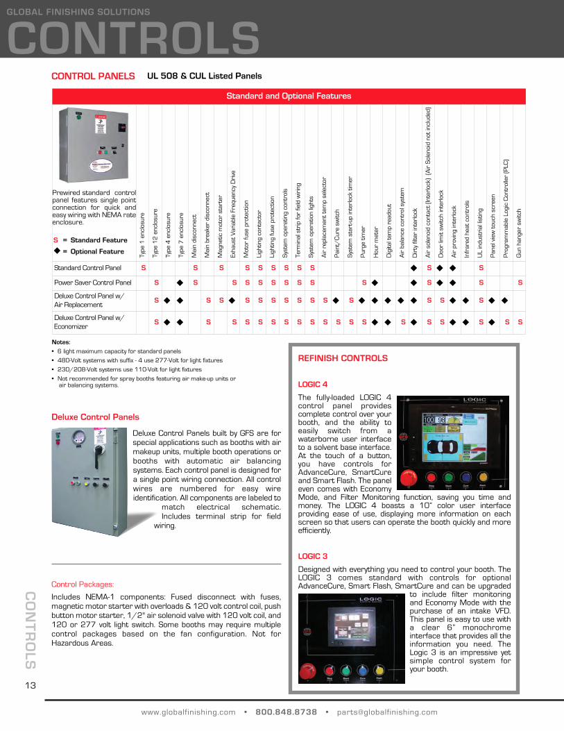
LOGIC 4
The fully-loaded LOGIC 4control panel providescomplete control over yourbooth, and the ability toeasily switch from awaterborne user interfaceto a solvent base interface.At the touch of a button,you have controls forAdvanceCure, SmartCureand Smart Flash. The paneleven comes with EconomyMode, and Filter Monitoring function, saving you time andmoney. The LOGIC 4 boasts a 10” color user interfaceproviding ease of use, displaying more information on eachscreen so that users can operate the booth quickly and moreefficiently.
LOGIC 3
Designed with everything you need to control your booth. TheLOGIC 3 comes standard with controls for optionalAdvanceCure, Smart Flash, SmartCure and can be upgraded
to include filter monitoringand Economy Mode with thepurchase of an intake VFD.This panel is easy to use witha clear 6” monochromeinterface that provides all theinformation you need. TheLogic 3 is an impressive yetsimple control system foryour booth.
13
AUTOMOTIVE - VFDs
Part No. Volt H.P.
134-069
575
20-30
134-071 40
134-073 60
134-240 1
134-241 2
134-242 3
134-243 5
134-244 7.5
134-245 10
134-250
200-240
1
134-251 2
134-252 3
134-253 5
134-254 7.5
134-255 10
134-256 15-20
134-260 25
134-261 30
134-262 50
134-265
380-480
1
134-266 2
134-267 3
134-268 5
134-269 7.5
134-270 10
134-271 15-20
134-273 25
134-274 30
134-275 40
134-276 50
134-500
230
7.5
ATV31HU55M3X
134-501 10
134-502 15
134-503 7.5
134-504 10
134-505 15
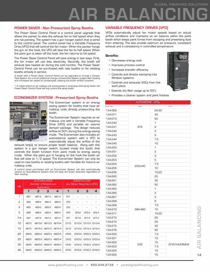
VARIABLE FREQUENCY DRIVES (VFD)VFDs automatically adjust fan motor speeds based on actualairflow conditions and maintains an air balance within the paintbooth which keeps paint fumes from escaping and preventing dustfrom entering. The also provide optimum air pressure, consistentexhaust and a consistency in controlled temperature.
Benefits:> Decreases energy cost
> Improves process control
> Increases transfer efficiency
> Controls and directs overspray intofiltration systems
> Controls and exhausts VOCs from thework place
> Extends dry filter usage up to 50%
> Provides a cleaner system and paint finishes
AIR
BA
LAN
CIN
G
www.globalfinishing.com • 800.848.8738 • [email protected]
GLOBAL FINISHING SOLUTIONS
HP
AUTO-BALANCENumber of Motors per
Application
1 2 3 4
1 AB1 AB1-2 AB1-3 AB1-4
2 AB2 AB2-2 AB2-3 AB2-4
3 AB3 AB3-2 AB3-3 AB3-4
5 AB5 AB5-2 AB5-3 AB5-4
7.5 AB7 AB7-2 AB7-3 AB7-4
10 AB10 AB10-2 AB10-3 AB10-4
15 AB15 AB15-2 AB15-3 AB15-4
20 AB20 AB20-2 AB20-3 AB20-4
25 AB25 AB25-2 AB25-3 AB25-4
30 AB30 AB30-2 AB30-3 AB30-4
40 AB40 AB40-2 AB40-3 AB40-4
CONSTA-FLOW(ea. Motor Requires a VFD)
1 2 3 4
CF1 -- -- --
CF2 -- -- --
CF3 -- -- --
CF5 CF5-2 CF5-3 CF5-4
CF7 CF7-2 CF7-3 CF7-4
CF10 CF10-2 CF10-3 CF10-4
CF15 CF15-2 CF15-3 CF15-4
CF20 CF20-2 CF20-3 CF20-4
CF25 CF25-2 CF25-3 CF25-4
CF30 CF30-2 CF30-3 CF30-4
CF40 CF40-2 CF40-3 CF40-4
POWER SAVER - Non Pressurized Spray BoothsThe Power Saver Control Panel is a control panel upgrade thatallows the painter to slow the exhaust fan to half speed when theyare not painting. The system has a gun hanger switch that is wiredto the control panel. The control panel has a Variable FrequencyDrive (VFD) that will control the fan motor. When the painter hangsthe gun on the hook, the VFD will slow the fan to half speed. Whenthe paint gun is taken off the hook, the fan returns to full speed.
The Power Saver Control Panel will save energy in two ways. First,the fan motor will use less electricity. Secondly, the booth willexhaust less heated air during the cold months. The Power SaverControl Panel can be purchased with new booths or for existingbooths already in service. A booth with a Power Saver Control Panel can be upgraded to include a Consta-Flow System for a small additional charge. Consta-Flow System judges filter loadingand increases fan speed to compensate, keeping the booth airflow constant.
ECONOMIZER SYSTEM - Pressurized Spray BoothsThe Economizer system is an energysaving system for booths that have airmakeup units directly pressurizing thebooth.
The Economizer System requires an airmakeup unit with a Variable FrequencyDrive (VFD) and variable air volumedamper package. This design reducesairflow to 50% during the energy savingmode. The Economizer also includes anauto-balance system with a VFD toautomatically adjust the airflow of the
exhaust fan(s), to ensure proper booth balance. Along with thissystem is a gun hanger switch, located inside the booth thatcontrols the booth function from paint mode to energy savingmode. When the paint gun is hanging on the hook the booth airflow will slow to 1/2 speed. The Economizer System can only beused on new booths or existing booths with Variable Air Volume airmakeup units.A control panel purchased with an Economizer System will also automaticallyreceive an Auto-Balance System that will keep the booth balanced regardless offilter loading.
AIR BALANCING
* In cases where an air makeup unit accompanies a nonpressurized spray booth, thePower Saver Control Panel will only control the spray booth.
14

4 - GUNHANGERTM
218-011 Spray booths, prep areas or anywhere inthe shop. Also works great in paint mixingrooms. Equipped with a tape holding hookfor storing tape, spray gun wrench andother needed items.
Dimensions; 7.5"w, 18.75"h, 7"d.
Approximate shipping weight: 7lb.
AC
CE
SS
OR
IES
www.globalfinishing.com • 800.848.8738 • [email protected]
ACCESSORIESGLOBAL FINISHING SOLUTIONS
SINGLE SPRAY GUNHANGERTM
218-004 A Magnetic spray gun holder, designed tohold all types of spray guns and mosttypes of air tools. Soft Edge guard toeliminate scratching of gun or gun cup.
Dimensions: 3"w, 5"d.
Approximate shipping weight: 2 lbs.
MEGAHOOKTM
218-014
218-015"U" Style
All purpose magnetic hooks that aregreat for the shop and, industrial orhome use. The Magahooks™ are usefulin holding a variety of objects to a metalsurface such as spray booth walls, partscaddys, lockers, toolboxes, warehouseracking, refrigerators and much more!
Dimensions: 2.65" Base, 65lb pull.
BOOTHSHELF CMTM
218-007 Corner mounted, 3-Position spray gunhanger and vented working shelf. Use the BoothShelf CM™ in the corner ofyour spray booth, mixing room or prep deck to hold spray guns, tack cloth, paint cups etc, for easy accesswhile painting. Works great as a smallmixing shelf. Equipped with soft edgeguard to eliminate scratching of gun orgun cup.
Dimensions: 21"w, 12.5"d.
Approximate shipping weight: 5 lbs.
BOOTHSHELF WMTM
218-009 A magnetic, 3-Position spray gun holder and vented working shelf combination. Usethe BoothShelf WM™ anywhere in thespray booth, mixing room or prep deck to hold spray guns, tape, tack cloth andother painting items for easy access while painting.
Dimensions: 14"w, 10"h, 8.5"d.
Approximate shipping weight: 8lb.
BOOTHBOX MINITM
--
218-006 A magnetic, single compartment cabinetand double spray gun holder, designed forthe interior of spray booths. Increaseefficiency and productivity by storing yourneeded painting items close at hand whenpainting. Avoid trips in and out of thebooth during a paint job!
Dimensions: 14"w, 7.25"h, 6"d.
Approximate shipping weight: 9 lb.
BOOTHBOX 2TM
218-002 A magnetic, double compartment cabinetand double spray gun holder, designed for the interior of spray booths. Increaseefficiency and productivity while eliminatingtime wasting trips in and out of the spraybooth. Store commonly used supplieswithin arms reach.
Dimensions: 15"w, 14"h, 6.5"d.
Approximate shipping weigh: 14 lb.
HOSE & GUNHANGERTM
218-013 Used for spray booths, prep areas oranywhere in the shop. Equipped witha tape holding hook for storing tapeor other needed items.
Dimensions: 7.5"w, 18.75"h, 7"d.
Approximate shipping weight: 7lb.
GFS SPRAY BOOTH ACCESSORIESPart No. Description Part No. Description
15
Karajen Corp. patent pending on all products GFS Spray Booth Accessories.
www.globalfinishing.com • 800.848.8738 • [email protected]
GLOBAL FINISHING SOLUTIONS
BLOWER HANGERTM
218-034 Use the Magnetic BLOWER HANGER™anywhere you need it, and easily aim yourportable blowers at the targets. Its widereach and pivoting movement make itextremely easy to use. There is no airpiping or booth retrofitting necessary.Maximize floor space in the booth byavoiding floor stands that are intendedfor the shop area.
Dimensions: 20” h, 12” w, 3” d with armsretracted, up to 24” d with armsextended fully extended.
Approximate ship weight: 16 lbs.
MIRROR HANGERTM
218-033 2-Part system for holding all sizes of mirrors, and other parts for painting.Just attach the mirror to the holdinghandle, lift the handle from the base andspray. Then, replace the handle back on the powerful magnetic base whileyour paint dries. No more hanging wiresin the booth or part horses just to paint a mirror.
PUMP BOTTLE HOLDERTM
218-032 Double magnetic hook sized for thecommon degreaser bottles that areusually scattered across prep carts, lyingon the floor or hanging from any ledgeavailable. Use the Magnetic Pump BottleHolder™ anywhere in the booth or preparea to keep bottles easily accessible.
The Pump Bottle Holder is also great forhanging a variety of pneumatic tools,spray guns and just about anything youcan imagine!
TEST PANEL HOLDERTM
218-023withClipboard
218-024withoutClipboard
Simplify Your Test Panel Process!
Attach paper or metal test panels, holdand spray! For flash and dry times, oreveryday storage, place the Test PanelHolder on the booth wall or other sheetmetal surface by its magnets.
GFS SPRAY BOOTH ACCESSORIESPart No. Description
Overspray accumulates quickly on spray booth walls, lights andwindows, potentially a highly flammable and spontaneouscombustion hazard. Consider using the following items to reducethe amounts of buildup, and improve booth illumination andoperator efficiency.
Strippable Spray Booth Coating
Part No. Description
236-040 5 Gal Clear Booth Coating, Solvent Base
236-041 5 Gal White Booth Coating, Solvent Base
Spray Booth Floor Covering
Part No. Description
217-081 Roll 36" x 500 ft, 70 mil Fire Retardant Paper
217-083 Roll 60" x 500 ft, 70 mil Fire Retardant Paper
217-084 Roll 72" x 500 ft, 70 mil Fire Retardant Paper
Light Fixture Lens Protector
Part No. Dimensions
230-210 12" x 100'
230-004 18" x 100'
230-211 Dispenser Handle
Cling-on clear plastic film for overspray. 2mil thickness, with custom acrylic adhesive.Easy to apply and easy to replace.
SPRAY BOOTH PROTECTION
Fast drying strippable coatings for spraybooths, paint booths, industrial floors andvarious surfaces such as paint boothsspray booths, glass, decal, storage partswood and others to protect it temporarilyduring industrial process or in materialhandling.
Call GFS for different products andadditional sizes available.
Blowers shown in picture are not included with the
BLOWER HANGER™.
AC
CE
SS
OR
IES
16
Karajen Corp. patent pending on all products GFS Spray Booth Accessories.
Spray Booth Wall & Floor Protection Material
Part No. Description
217-112 28" wide x 300' roll
217-110 Dispenser
A specially engineered adhesive-backedwhite material designed to protect boothwalls and floors, to trap dirt and paintoverspray, and brighten the work area.

MY
PA
RT
S LIS
T
www.globalfinishing.com • 800.848.8738 • [email protected]
GLOBAL FINISHING SOLUTIONS
MY PARTS LIST
Common Parts Ordered
GFS Part Number Description
Spray Boothy Serial #:_______________________
Model:_____________________
Common Parts Ordered
GFS Part Number Description
Spray Boothy Serial #:_______________________
Model:_____________________
17

GLOBAL (the Sellers) warrants to the original end-user buyer (the buyer) that the equipment manufactured by, and purchased from,the Seller (the Equipment), if properly installed in accordance with the Seller’s Service Manual, operated, and maintained, and usedunder normal conditions, shall be free from defects in workmanship and materials for a period of one (1) year from the date theEquipment is shipped from the facilities of the Seller. The obligation of the Seller, and the Buyer’s SOLE AND EXCLUSIVE REMEDYhereunder, shall be limited to one of the following, at the Seller’s option:
(01) The repair or replacement of defective parts or components (collectively, the Parts) of the Equipment; provided, however,the Buyer shall be responsible for the payment of all labor costs associated with any such repair or replacement.
(02) In the event the Seller is unable to repair or replace the defective Parts, the Buyer shall be entitled to a refund of the costof the Parts.
The Seller shall have no obligation under this Limited Warranty for ordinary wear and tear of the Equipment; if installation of theEquipment does not comply with local, state and federal requirements or laws; or if the Equipment is modified by any other personor organization. The Seller makes no warranty of any kind whatsoever with respect to Parts, which are manufactured or supplied byother persons or organizations (an OEM); provided, however, the Seller shall reasonably assist the Buyer in connection withwarranties, if any, provided by an OEM.
Warranty Performance Procedures
In the event the Buyer believes the Seller may be responsible for the performance of any warranty obligation, the Buyer mustimmediately send written notice of a claimed defect, and must immediately refrain from any further use of the affected Equipment.No attempted repair of the claimed defect may be made without the prior written consent of the Seller. Before any Parts can bereturned to the Seller, the Buyer must contact the Seller and request a Return Authorization. Upon the Buyer’s receipt of the ReturnAuthorization form, the Parts may be shipped, freight prepaid, to the facility designated on the Return Authorization. All Partsreturned for repair, replacement, or refund (a refund may be made in the form of a credit to the Buyer’s account), must beaccompanied by the Return Authorization. All returned parts are subject to a thirty percent (30%) handling charge. Partsmanufactured or supplied by an OEM are subject to the warranties, if any provided by such OEM’s; and repair or replacement of suchParts are subject to the approval of the OEM. The Buyer shall be responsible for the payment of any handling or restocking chargesassociated with OEM Parts.
Disclaimers of Warranties
THE WARRANTIES CONTAINED HEREIN ARE EXPRESSLY IN LIEU OF ANY OTHER EXPRESSED OR IMPLIED WARRANTIES, OR ANYOTHER OBLIGATION ON THE PART OF THE SELLER, INCLUDING WITHOUT LIMITATION, ANY IMPLIED WARRANTY OFMERCHANTABILITY OR FITNESS FOR A PARTICULAR PURPOSE. ANY MODELS, DRAWINGS, PLANS, SPECIFICATIONS,AFFIRMATION OF FACT, PROMISES, OR OTHER COMMUNICATIONS BY THE SELLER WITH THE REFERENCE TO THE EQUIPMENTOR THE PERFORMANCE OF THE EQUIPMENT ARE SOLELY FOR THE CONVENIENCE OF THE BUYER AND SHALL NOT IN ANY WAYMODIFY THE EXPRESSED WARRANTIES AND DISCLAIMERS SET FORTH HEREIN. THE BUYER ACKNOWLEDGES IT IS PURCHASINGTHE EQUIPMENT SOLELY ON THE BASIS OF THE COMMITMENTS FOR THE SELLER AS EXPRESSLY SET FORTH HEREIN. NOAGENTS OR OTHER PARTIES ARE AUTHORIZED TO MAKE ANY WARRANTIES ON BEHALF OF THE COMPANY OR TO ASSUME FORTHE COMPANY ANY OTHER LIABILITY OR OBLIGATION IN CONNECTION WITH THE EQUIPMENT.
Consequential Damages
The Seller shall not be liable for any incidental or consequential damages arising from the use of the equipment by the Buyer, thebreach of any warranties, the failure to deliver, delay in delivery, delay on nonconforming condition, or for any other breach of contractor duty between the Seller and the Buyer.
Limitation of Actions
Any action resulting from the breach of any warranty contained herein by the Seller must be commenced within one (1) year afterthe cause of action accrues. In no event shall the Seller’s total liability for any or all breaches of any warranty exceed the actualpurchase price paid by the Buyer for the Equipment.
12731 Norway Road l P.O. Box 250 l Osseo, Wisconsin 54758-0250Phone: (800) 848-8738 l Fax: (715) 597-2193
www.globalfinishing.com
®
LIMITED WARRANTY

Contact GFS for your local distributor!
gfs’ quest for product quality and performance has resulted in a full line of accessories that have been designed and manufactured for durability and long lasting, trouble-free service. great emphasis is placed on our engineering and workmanship so that gfs customers will receive the best products at competitive prices.
gfs is also your approved full-line supplier for Parts and filters for:
> binks booths
> DeVilbiss booths
> Jbi booths & ovens
> blu-surf systems
> milbanks systems
> other spray booth manufacturers
(800) [email protected]
Approved Replacement Parts and Filters
© 2011 global finishing solutions®
all Rights Reserved
accEssoRiEs 02222011
consult your global finishing solutions sales representative for details of required installation, concrete pit, electrical wiring, conduit, air piping, roof penetrations and automatic fire suppression. The equipment installation location should be reviewed and approved by the local authorities having jurisdiction. all designs, specifications and components are subject to change at the manufacturer’s sole discretion at any time without notice. Data published herein is informational in nature and shall not be construed to warrant suitability of the unit for any particular purpose as performance may vary with the conditions encountered.
global finishing solUTions • 800-848-8738 • [email protected]
w w w . g l o b a l f i n i s h i n g . c o m
follow gfs:
twitter.com/globalfinishing
facebook.com/globalfinishing
Use your smart phone to visit our website:
®G L O B A L F I N I S H I N G S O L U T I O N S