glenfield structure plan - city of greater geraldton · 4.1 community design 9 4.1.1 sense of place...
TRANSCRIPT

Glenfield Structure Plan
- 1 -
GLENFIELD STRUCTURE PLAN
November 2010
Adopted by Council on 23 November 2010

Glenfield Structure Plan
- 2 -
1 INTRODUCTION 4
1.1 DEVELOPMENT OF THE PLAN 4
1.2 PURPOSE OF THE PLAN 5
2 EXISTING SITE AND CONTEXT ANALYSIS 6
2.1 LOCATION, AREA AND OWNERSHIP 6
2.2 EXISTING AND SURROUNDING LAND USE 6
2.3 LANDFORM 6
2.4 VEGETATION 7
2.4.1 Regionally Significant Vegetation 7
2.5 ABORIGINAL SITES 7
3 PLANNING CONTEXT 8
3.1 REGIONAL PLANNING 8
3.1.1 Geraldton Region Plan 8
3.1.2 Northern Geraldton District Structure Plan (draft) 8
3.2 LOCAL PLANNING 8
3.2.1 Local Planning Scheme 8
3.2.2 Local Rural Strategy 8
3.2.3 Local Planning Strategy 8
3.2.4 Geraldton-Greenough Retail and Services Strategy 8
4 THE STRUCTURE PLAN 9
4.1 COMMUNITY DESIGN 9
4.1.1 Sense of Place 9
4.1.2 Land Use Rationale 9
4.2 MOVEMENT NETWORK 10
4.2.1 Road Network 10
4.2.1.1 North-West Coastal Highway 10
4.2.1.2 Chapman Road 10
4.2.1.3 Other Roads 10
4.2.2 Public Transport 10
4.2.3 Pedestrians and Cyclists 11
4.3 ACTIVITY CENTRES AND EMPLOYMENT 11
4.3.1 Mixed Use 11
4.3.2 Local Activity Nodes 12
4.3.3 Community Purpose Sites 12
4.3.4 Special Use 12
4.3.5 Employment 13
4.4 LOT LAYOUT 13
4.4.1 Lot Size and Variety 13
4.4.1.1 Alexander Drive R5 13
4.4.1.2 Chapman Road R5/40 14
4.4.1.3 Residential R20 14
4.4.1.4 Residential R40 14
4.4.1.5 Residential R60 15
4.4.1.6 Mixed Use R80 15
4.4.1.7 Special Use 15
4.4.2 Density Target and Population 15
4.4.3 Climate Responsive Design 16
4.5 PUBLIC PARKLAND 16
4.6 SCHOOLS 18
4.7 URBAN WATER MANAGEMENT 18
4.8 UTILITIES 19
4.8.1 Water 19
4.8.2 Sewerage 19
4.8.3 Power 19

Glenfield Structure Plan
- 3 -
5 IMPLEMENTATION 20
5.1 ACTIVITY CENTRE PLANNING 20
5.2 SUBDIVISION GUIDE PLANS 20
5.3 DETAILED AREA PLANNING 21
5.4 INTERIM SUBDIVISION 21
5.4.1 Chapman Road Residential R5 21
5.4.2 Subdivision of Existing Housing 22
5.5 DEVELOPER CONTRIBUTIONS 22
5.5.1 Drainage 22
5.5.2 Major Roads 22
5.5.3 Schools 22
5.5.4 Servicing 23
5.5.5 Public Open Space 23
6 CONCLUSION 24
TABLES
Table 1 – PROPOSED BROAD LAND USES 9
Table 2 – RETAIL CALCULATIONS 12
Table 3 – POTENTIAL EMPLOYMENT 13
Table 4 – URBAN DENSITY CALCULATIONS 15
Table 5 – OVERALL PUBLIC OPEN SPACE SCHEDULE 17
Table 6 – PUBLIC OPEN SPACE SCHEDULE BY LOT 17
FIGURES
Figure 1 – LOCATION PLAN
Figure 2 – STRUCTURE PLAN AREA
Figure 3 – AERIAL PHOTOGRAPH
Figure 4 – VEGETATION MAPPING
Figure 5 – GERALDTON REGION PLAN
Figure 6 – ZONING PLAN
Figure 7 – PEDESTRIAN & CYCLE NETWORK
Figure 8 – INDICATIVE AREA FOR PRIMARY SCHOOL
GLENFIELD STRUCTURE PLAN
APPENDICES
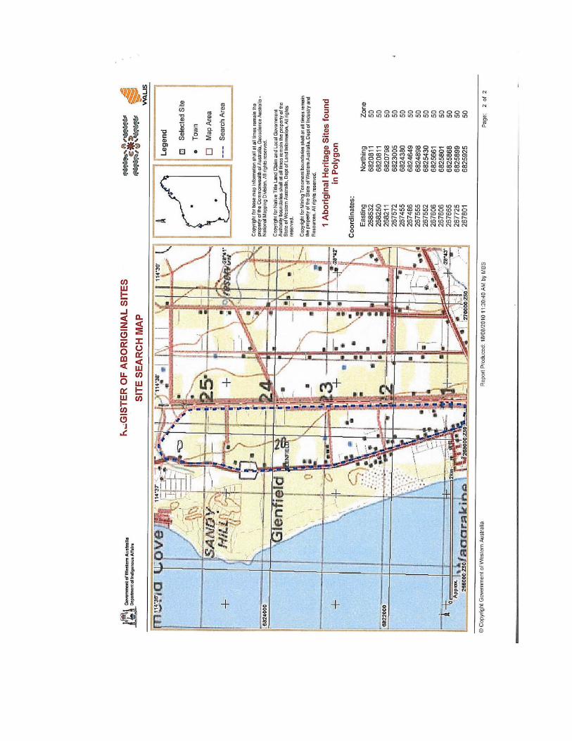
Appendix A – REGISTER OF ABORIGINAL SITES
Appendix B – MAIN ROADS WA ADVICE
Appendix C – DEPARTMENT OF EDUCATION ADVICE
Appendix D – STORMWATER AND DRAINAGE MANAGEMENT PLAN
Glenfield Structure Plan
- 4 -
1 INTRODUCTION
1.1 Development of the Plan
The Glenfield strip bordered by
Chapman Road to the west and the
North-West Coastal Highway to the east
was zoned for residential purposes
under Town Planning Scheme No. 4
(Greenough), on 30 March 1984. The
subsequent structure planning for the
Glenfield area was undertaken
sporadically, involving several drafts
and rounds of public consultation prior
to endorsement of the Glenfield
Structure Plan by the former Shire of
Greenough at its meeting held on 30
January 2002 and by the WA Planning
Commission (WAPC) on 12 March 2002.
In August 2007, the WAPC advised that
there was now not enough detail
shown on the Glenfield Structure Plan to
allow subdivision to be approved with
confidence. They further advised that,
“…a decision has been made not to
approve any further subdivision in the
Glenfield locality until a structure plan
with sufficient detail has been prepared
and adopted …”
In light of this approach by the WAPC,
the City undertook updates to the
Glenfield Structure Plan regarding
(amongst other things) Main Roads WA
requirements for widening of the North-
West Coastal Highway and engaged
consultants to prepare a district
drainage investigation.
A preliminary draft of the updated
Glenfield Structure Plan was emailed in
January 2008 to the [then] Department
of Planning & Infrastructure, Geraldton
office seeking preliminary feedback.
In March 2008, the WAPC
“…considered the currently endorsed
Glenfield Structure Plan 2002 and
resolved to advise the City that it is not
prepared to support any further
subdivision at this time and considers
the Glenfield Structure Plan 2002 as
suspended.” Additionally, the WAPC
asked the [then] Department for
Planning & Infrastructure to assist the
City in developing a new Plan and also
advised that a request would be made
for the WAPC to financially support the
City in addressing specific issues.
Since then the City had been working
with the Department of Planning on
finalising a new Glenfield Structure Plan
and significant progress was made in
addressing the strategic issues
identified.
In August 2008 the City received
correspondence from the WAPC
advising that it had now resolved to
advise the City that the Department of
Planning did not have any further
resources available to assist in
progressing the Glenfield Structure Plan
and further, to issue conditional
approval for the outstanding subdivision
applications where they are in general
accordance with the existing Glenfield
Structure Plan 2002 (which had been
suspended in March 2008).
As a result of this the City expedited the
preparation of this new Structure Plan
for Glenfield.
Glenfield Structure Plan
- 5 -
1.2 Purpose of the Plan
It is envisaged that with the future
development of the Oakajee Industrial
Site that considerable increases in the
population of the northern suburbs of
the City of Geraldton-Greenough will
occur, and hence the City recognises
the need to provide structure planning
for existing residential zoned areas such
as Glenfield.
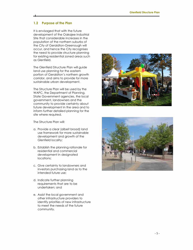
The Glenfield Structure Plan will guide
land use planning for the eastern
portion of Geraldton’s northern growth
corridor, and aims to provide for more
sustainable urban development.
The Structure Plan will be used by the
WAPC, the Department of Planning,
State Government agencies, the local
government, landowners and the
community to provide certainty about
future development in the area and to
inform further detailed planning for the
site where required.
The Structure Plan will:
a. Provide a clear (albeit broad) land
use framework for more sustainable
development and growth of the
Glenfield locality;
b. Establish the planning rationale for
residential and commercial
development in designated
locations;
c. Give certainty to landowners and
investors purchasing land as to the
intended future use;
d. Indicate further planning
requirements that are to be
undertaken; and
e. Assist the local government and
other infrastructure providers to
identify priorities of new infrastructure
to meet the needs of the future
community.

Glenfield Structure Plan
- 6 -
2 EXISTING SITE AND CONTEXT
ANALYSIS
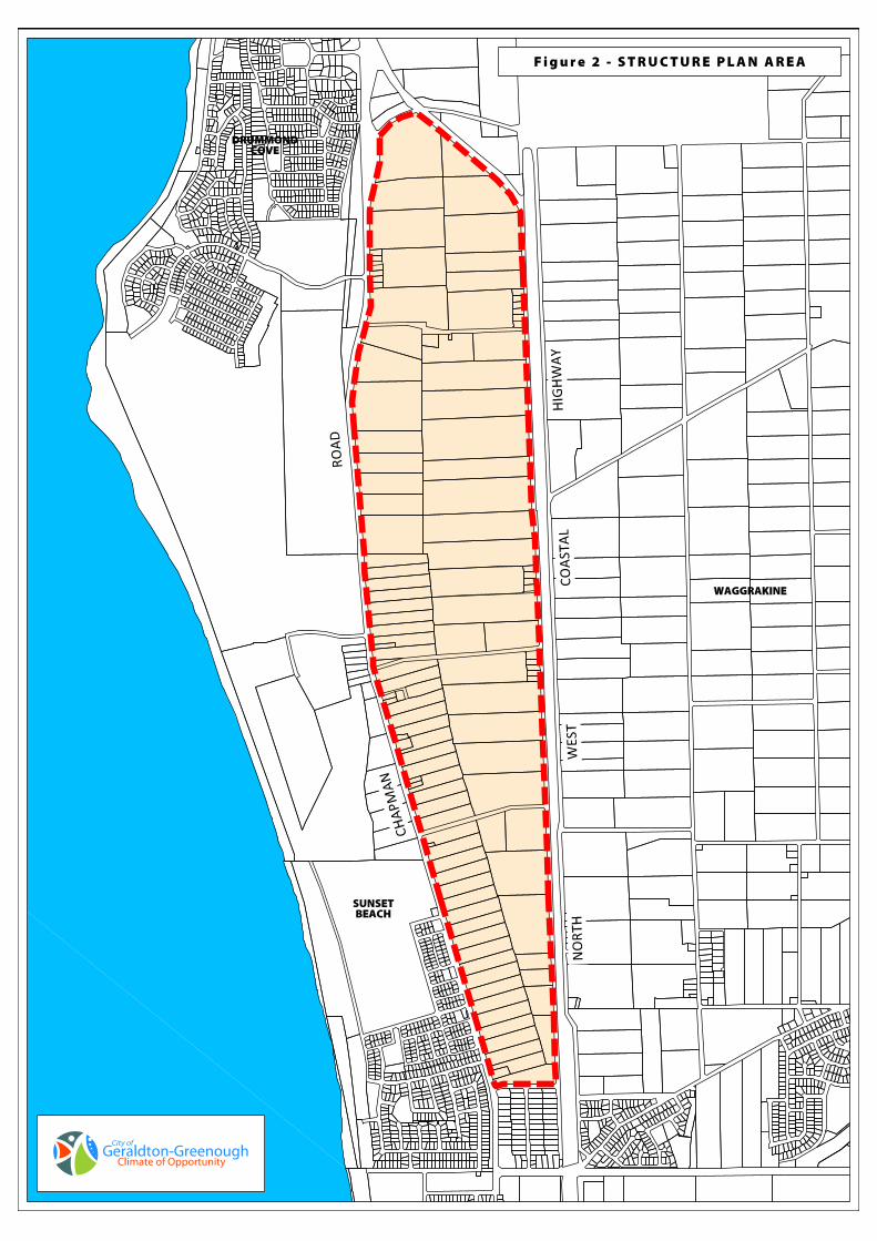
2.1 Location, Area and Ownership
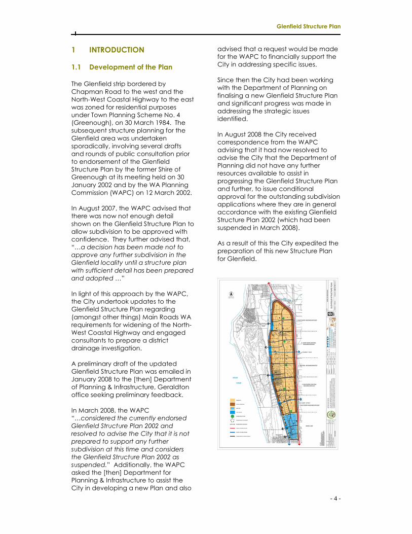
The Glenfield Structure Plan area is
located approximately 7km north of the
Geraldton CBD and is situated in the
northern growth corridor of the
Geraldton townsite. It is located
approximately 1km from the Indian
Ocean coastline and fringes the Sunset
Beach and Drummond Cove localities
to the West (Figure 1).
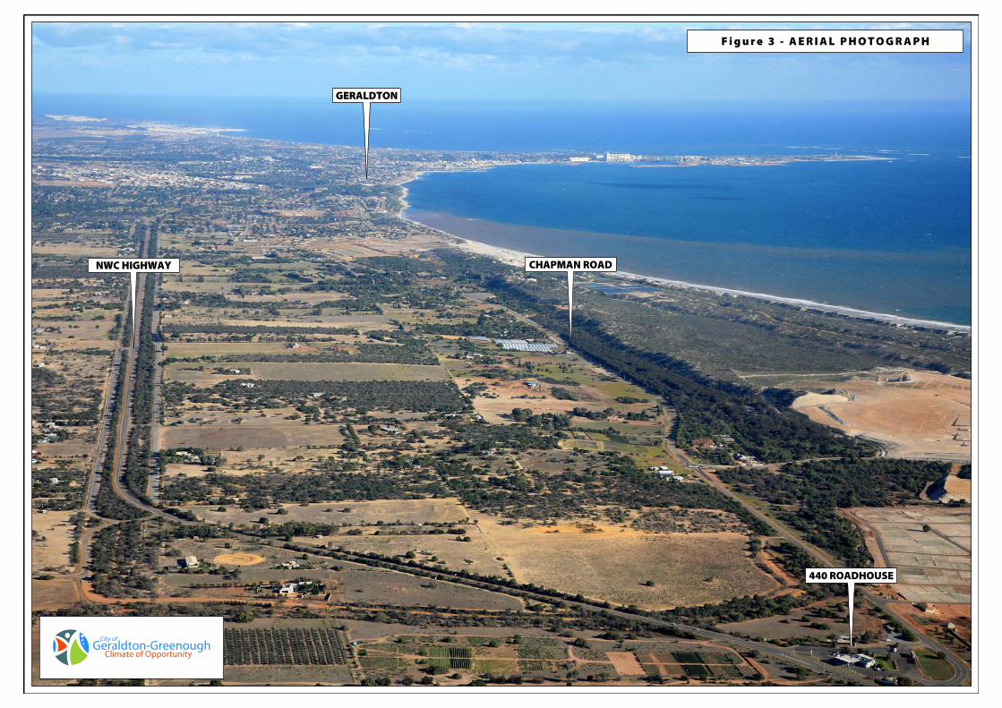
The Structure Plan covers approximately
368ha of land and relates to the area
generally bounded by the North-West
Coastal Highway to the east and north-
east, Chapman Road to the west,
Dulchev Way to the north-west and
Stella Street to the south (Figures 2 & 3).
The area comprises over 120 private
land holdings, and whilst several
properties are in common ownership,
the area predominantly comprises
multiple land ownership.
2.2 Existing and Surrounding Land Use
The major existing land uses within the
Structure Plan area comprises of
residential, rural-residential, market
gardening and other mixed uses. The
mixed uses invariably include a
residence as well as some other activity.
These other activities range from nursery
activities to a large building material
supply business. Market gardening has
lessened as an activity in this locality
over recent times and the predominant
use is now low density and rural-
residential.
Land to the north of the study area, on
the east side of the North-West Coastal
Highway has been mooted for “Special
Residential” use and a small section
known as “Drummond Heights Estate”
has been developed. Also to the north
a future neighbourhood shopping
centre is proposed at the 440
Roadhouse site.
East of the study area the land is
presently occupied by rural lots in the
range of 4-10ha. This area has been
identified for future “Rural-Residential”
development. The Waggrakine
Development Scheme area is located
to the south-east of the study area and
facilitates traditional single residential
development.
West of the study area, the coastal
fringes require structure planning for
future residential and associated land
uses (such as schools and shopping)
which connect the existing residential
subdivisions of Sunset Beach in the south
with Drummond Cove in the north.
Central to this area the Water
Corporation’s Geraldton Wastewater
Treatment Plant No. 3 is located.
Residential uses occur to the south of
the study area with a neighbourhood
shopping centre (Sunset) located south
of Stella Street.
2.3 Landform
A dominant ridge dissects the area from
Okahoma Road to Dulchev Way. Land
situated above the ridge line gently
slopes upwards towards Alexander
Drive and has ocean and city views.
The land below, west of the ridge
extending from Macedonia Drive to
Okahoma Road inclines from 20m to
flatten out at 4m along Chapman
Road. As the ridge veers eastward the
topography below the ridgeline
changes to gently undulating slopes
which incline southwards. South of
Okahoma Road the land dips and
inclines to flatten out near Chapman
Road.
Glenfield Structure Plan
- 7 -
The study area is situated on a belt of
coastal limestone which is part of the
pleistocene consolidated dune swale
system of Tamala limestone. Two major
soil types are prevalent in the study
area.
A belt of deep red coarse to loamy
sand on the seaward side, and a
uniform yellow sand plain which
commonly has a loose brown or dark
brown loam sand surface over a
yellowish brown loamy sand. Both soils
show a high capability to sustain both
urban and rural-residential
developments as they are
characteristically rapidly drained, allow
for foundation soundness, ease of
excavation, nil slope instability risk and
have moderate agricultural potential.
2.4 Vegetation
The vegetation cover reflects the
topography and rainfall patterns. A
large proportion of the land has been
cleared especially within a wide belt
through the centre of the study area.
Road reserves are generally lined by
scrub and residential blocks close to
these road reserves are landscaped
with trees and bush.
Vegetation (based on Beard’s
vegetation mapping) associated with
the deep red soils are Acacia ligulata,
low woodland with low refociffium and
Acacia spathulatum as other common
trees. Remnants of the sand plain
include open Banksia/Acacia
woodland. Common species include
Acacia rostellifera, Banksia priomotes,
Dryandra sessilis and Grevillea
candelabroides.
2.4.1 Regionally Significant Vegetation
The WAPC produced the Geraldton
Regional Plan in 1999 to provide a
regional framework for planning
decisions. It was acknowledged by the
Environmental Protection Authority
(EPA) in its comments on the plan, that
a regional native vegetation survey was
required for the Geraldton region to
provide a regional context for decisions
on development proposals that have
the potential to impact on remnant
vegetation. The EPA recommended
that areas supporting regionally
significant vegetation be identified for
conservation.
In 2008, the WAPC in partnership with
relevant State government agencies
and local government, commenced
the Geraldton Regional Flora and
Vegetation Survey Project (GRFVS). The
GRFVS has mapped and described
vegetation types occurring in the
Geraldton region, focusing on areas
where significant land use change or
development is proposed.
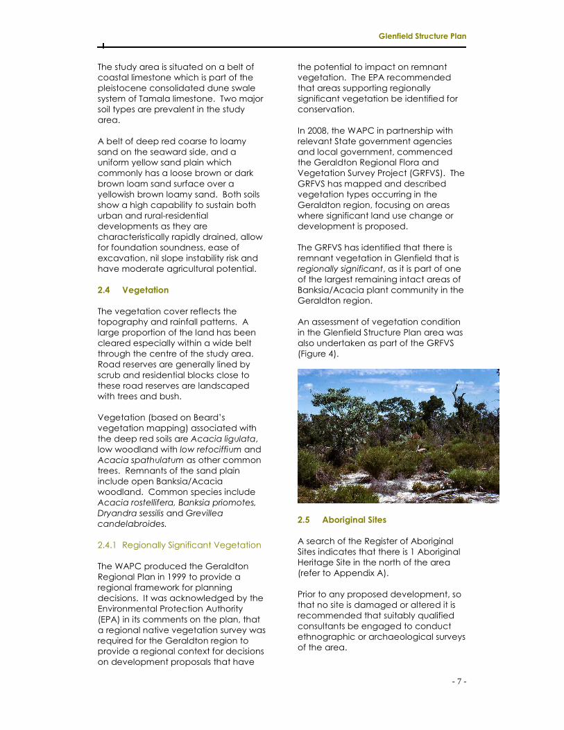
The GRFVS has identified that there is
remnant vegetation in Glenfield that is
regionally significant, as it is part of one
of the largest remaining intact areas of
Banksia/Acacia plant community in the
Geraldton region.
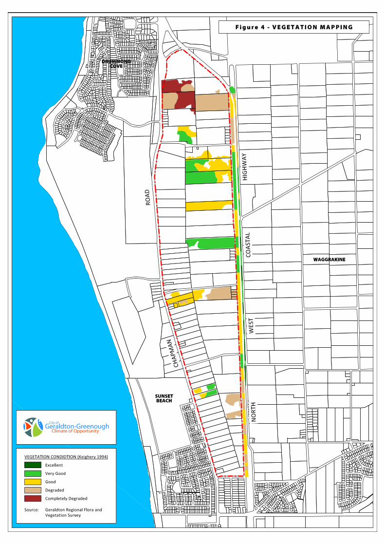
An assessment of vegetation condition
in the Glenfield Structure Plan area was
also undertaken as part of the GRFVS
(Figure 4).
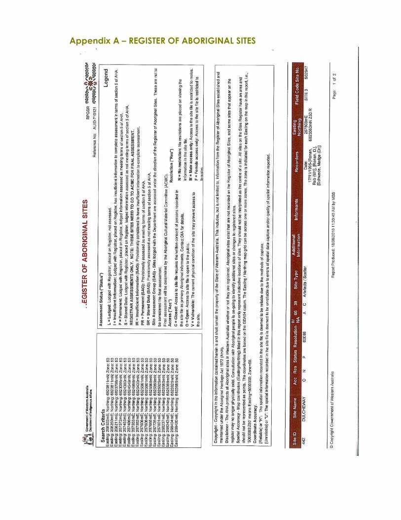
2.5 Aboriginal Sites
A search of the Register of Aboriginal
Sites indicates that there is 1 Aboriginal
Heritage Site in the north of the area
(refer to Appendix A).
Prior to any proposed development, so
that no site is damaged or altered it is
recommended that suitably qualified
consultants be engaged to conduct
ethnographic or archaeological surveys
of the area.
Glenfield Structure Plan
- 8 -
3 PLANNING CONTEXT
3.1 Regional Planning
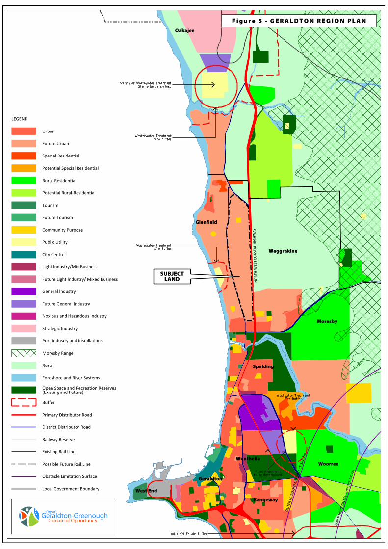
3.1.1 Geraldton Region Plan
The Geraldton Region Plan provides a
broad regional planning framework for
the growth and development of the
greater Geraldton urban area over the
next 20 to 30 years. It seeks to provide a
framework for the future management,
protection and coordination of regional
planning in the region and allocates the
general location and extent of land
uses at a broad scale. The document
identifies the Structure Plan area as
future urban (Figure 5).
3.1.2 Northern Geraldton District
Structure Plan (draft)
The purpose of this study is to provide a
district structure plan for northern
Geraldton that progresses key elements
of the Greater Geraldton Structure Plan
(produced as part of the Geraldton
Region Plan 1999) and identifies
principles that will guide future
development within the study area.
The district structure plan is in a draft
stage only but incorporates many of
the design elements within this Structure
Plan.
3.2 Local Planning
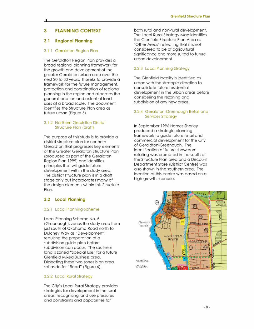
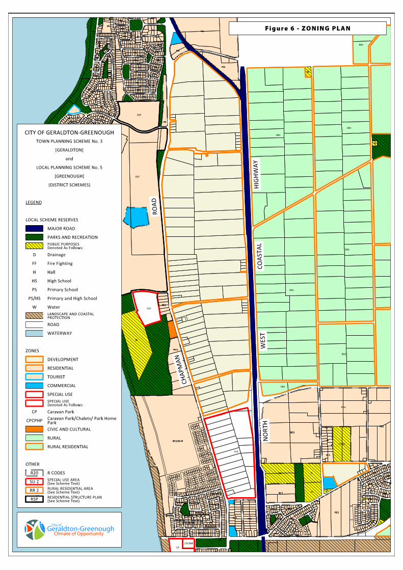
3.2.1 Local Planning Scheme
Local Planning Scheme No. 5
(Greenough), zones the study area from
just south of Okahoma Road north to
Dulchev Way as “Development”
requiring the preparation of a
subdivision guide plan before
subdivision can occur. The southern
land is zoned “Special Use” for a future
Glenfield Mixed Business area.
Dissecting these two zones is an area
set aside for “Road” (Figure 6).
3.2.2 Local Rural Strategy
The City’s Local Rural Strategy provides
strategies for development in the rural
areas, recognising land use pressures
and constraints and capabilities for
both rural and non-rural development.
The Local Rural Strategy Map identifies
the Glenfield Structure Plan Area as
‘Other Areas’ reflecting that it is not
considered to be of agricultural
significance and more suited to future
urban development.
3.2.3 Local Planning Strategy
The Glenfield locality is identified as
urban with the strategic direction to
consolidate future residential
development in the urban areas before
considering the rezoning and
subdivision of any new areas.
3.2.4 Geraldton-Greenough Retail and
Services Strategy
In September 1996 Hames Sharley
produced a strategic planning
framework to guide future retail and
commercial development for the City
of Geraldton-Greenough. The
identification of future showroom
retailing was promoted in the south of
the Structure Plan area and a Discount
Department Store (District Centre) was
also shown in the southern area. The
location of this centre was based on a
high growth scenario.
Glenfield Structure Plan
- 9 -
4 THE GLENFIELD STRUCTURE
PLAN
4.1 Community Design
4.1.1 Sense of Place
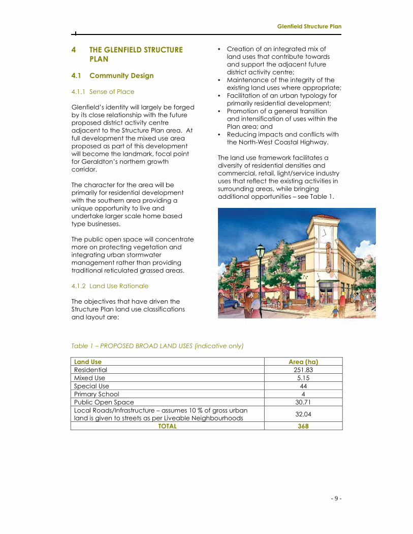
Glenfield’s identity will largely be forged
by its close relationship with the future
proposed district activity centre
adjacent to the Structure Plan area. At
full development the mixed use area
proposed as part of this development
will become the landmark, focal point
for Geraldton’s northern growth
corridor.
The character for the area will be
primarily for residential development
with the southern area providing a
unique opportunity to live and
undertake larger scale home based
type businesses.
The public open space will concentrate
more on protecting vegetation and
integrating urban stormwater
management rather than providing
traditional reticulated grassed areas.
4.1.2 Land Use Rationale
The objectives that have driven the
Structure Plan land use classifications
and layout are:
• Creation of an integrated mix of
land uses that contribute towards
and support the adjacent future
district activity centre;
• Maintenance of the integrity of the
existing land uses where appropriate;
• Facilitation of an urban typology for
primarily residential development;
• Promotion of a general transition
and intensification of uses within the
Plan area; and
• Reducing impacts and conflicts with
the North-West Coastal Highway.
The land use framework facilitates a
diversity of residential densities and
commercial, retail, light/service industry
uses that reflect the existing activities in
surrounding areas, while bringing
additional opportunities – see Table 1.
Table 1 – PROPOSED BROAD LAND USES (indicative only)
Land Use Area (ha)
Residential 251.83
Mixed Use 5.15
Special Use 44
Primary School 4
Public Open Space 30.71
Local Roads/Infrastructure – assumes 10 % of gross urban
land is given to streets as per Liveable Neighbourhoods 32.04
TOTAL 368

Glenfield Structure Plan
- 10 -
4.2 Movement Network
The key to enabling the intensive, mixed
use redevelopment of Glenfield is the
establishment of a safe, legible and
effective movement network for all
users.
4.2.1 Road Network
4.2.1.1 North-West Coastal
Highway
The major north-south road that runs
through Geraldton is the North-West
Coastal Highway which is classified as a
primary distributor road. Currently full
interchanges are provided onto the
Highway from Macedonia Drive and
Okahoma Road only.
The Highway’s suitability for heavy
vehicle usage should not be
compromised and for this reason, future
development along the Highway needs
to minimise lot frontage and
commercial activity. At present the
Highway is constructed to a 2 lane
undivided carriageway standard. Main
Roads WA (MRWA) in their future
planning have allowed for upgrading to
a 4 lane divided carriageway standard.
The Structure Plan proposes to retain
the connection from Macedonia Drive
with the Highway and close the
connection with Okahoma Road. A
new connection is proposed north of
Hagan Road on the northern boundary
of Lot 123 which will provide the main
east-west ‘spine’ connecting the
Highway with the future district activity
centre. A third, 4-way connection is
proposed utilising the existing road
reservation shown in the town planning
scheme. This will provide permeability
across the Highway from the
Waggrakine residential area to the
east.
4.2.1.2 Chapman Road
Chapman Road is classified as an
integrator road primarily servicing the
city centre. It is considered to provide
the appropriate combination of traffic
exposure and volumes to support
neighbourhood and district activity
centres. No further road connections
should be permitted other than those
shown on the Plan.
Although at this stage direct access
onto Chapman Road is permitted, it is
envisaged that with the development
of the Structure Plan that this access will
be restricted.
Should direct access to Chapman
Road from adjacent lots be restricted in
the future, access is to be provided
from a local road parallel to Chapman
Road within the Structure Plan area.
The exact alignment of the road will be
determined at further detailed planning
stages. Subdividers in this location may
be required to provide land for road
reserve purposes.
4.2.1.3 Other Roads
The road concept for the Structure Plan
has been influenced in the first instance
by the existing road configurations, and
secondly by the need to achieve a
basic grid configuration to maximise
permeability, legibility and robustness.
The roads are diagrammatically shown
on the Structure Plan and are
considered essential to ensure a basic
level of permeability is achieved
throughout the area. Other local road
networks will be detailed through the
subdivision process.
4.2.2 Public Transport
Bus services currently connect Sunset
with Drummond Cove via Chapman
Road. In the longer term it is proposed
that this primary route be retained to
connect the proposed activity centres.
Additional routes may be provided
along the three road connections with
the North-West Coastal Highway.
Glenfield Structure Plan
- 11 -
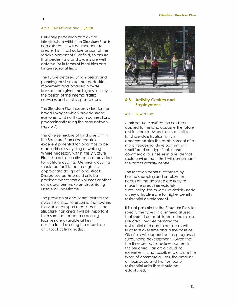
4.2.3 Pedestrians and Cyclists
Currently pedestrian and cyclist
infrastructure within the Structure Plan is
non-existent. It will be important to
create this infrastructure as part of the
redevelopment of Glenfield, to ensure
that pedestrians and cyclists are well
catered for in terms of local trips and
longer regional trips.
The future detailed urban design and
planning must ensure that pedestrian
movement and localised bicycle
transport are given the highest priority in
the design of the internal traffic
networks and public open spaces.
The Structure Plan has provided for the
broad linkages which provide strong
east-west and north-south connections
predominantly using the road network
(Figure 7).
The diverse mixture of land uses within
the Structure Plan area creates
excellent potential for local trips to be
made either by cycling or walking.
Where necessary within the Structure
Plan, shared use paths can be provided
to facilitate cycling. Generally, cycling
should be facilitated through the
appropriate design of local streets.
Shared use paths should only be
provided where traffic volumes or other
considerations make on-street riding
unsafe or undesirable.
The provision of end of trip facilities for
cyclists is critical to ensuring that cycling
is a viable transport mode. Within the
Structure Plan area it will be important
to ensure that adequate parking
facilities are available at key
destinations including the mixed use
and local activity nodes.
4.3 Activity Centres and
Employment
4.3.1 Mixed Use
A mixed use classification has been
applied to the land opposite the future
district centre. Mixed use is a flexible
land use classification which
accommodates the establishment of a
mix of residential development with
small “boutique type” retail and
commercial businesses in a residential
scale environment that will compliment
the district activity centre.
The location benefits afforded by
having shopping and employment
needs on the doorstep are likely to
make the areas immediately
surrounding the mixed use activity node
a very attractive site for higher density
residential development.
It is not possible for the Structure Plan to
specify the types of commercial uses
that should be established in the mixed
use area. Market demand for
residential and commercial uses will
fluctuate over time and in the case of
Glenfield will depend on the progress of
surrounding development. Given that
the time period for redevelopment in
the Structure Plan area could be
extensive, it is not possible to dictate the
types of commercial uses, the amount
of floorspace and the number of
residential units that should be
established.

Glenfield Structure Plan
- 12 -
The provision of retail/commercial
floorspace was based on the floor
space provision requirements of the
WAPC Perth Metropolitan Centres
Policy and the Guidelines for the
Preparation of Local Structure Plans for
Urban Release Areas June 1992 (ie. a
total of 1.49m2 per household). In order
to determine the land area requirement
for commercial uses a floor space to
land area ratio was adopted, which is
reflective of the existing commercial
centres in Geraldton and was used in
the Northern Geraldton District Structure
Plan. The retail calculations excluded
retail/commercial facilities that may
eventuate in the Special Use area – see
Table 2.
Table 2 – RETAIL CALCULATIONS (indicative only)
Total Estimated Dwellings 5,324 dwellings
NLA Floorspace Provision 1.49 m² x 5,324 dwellings 7,933m2
Land Requirement * 2.4 ha
Mixed Use ** 2.58 ha
* Assumes 1/3 floor space and 2/3 land for parking, landscaping, access etc.
** Assumes 50% of land area will not be used for retail purposes.
4.3.2 Local Activity Nodes
Local activity nodes may quite
appropriately occur throughout the
Structure Plan area and are
encouraged to provide for the needs of
the communities and provide for the
daily shopping needs. Market demand
for these nodes will dictate the
development of these areas and
accompanying them should be a
‘mantle’ of medium density residential
development in and around the nodes.
It is anticipated that these areas will be
developed to a density of R40. Retail
use should be street based in its built
form with any off-street car parking
located to the rear of the properties.
4.3.3 Community Purpose Sites
Sites for community facilities such as
community centres, meeting halls,
branch libraries, kindergartens, pre-
schools and day care centres are
increasingly important for community
development. The mixed use area
should be the focus for locating high-
end community facilities whilst the local
activity nodes may also support other
community based uses.
Specific sites are not shown on the
Structure Plan and should be allocated
as a result of detailed subdivision design
and/or a community needs assessment.
Given the estimated number of
dwellings, it is envisaged that 3 sites
may develop over time.
4.3.4 Special Use
The City is keen to encourage a
composite business/residential zone
where residents may reside on larger
lots and undertake large scale home
based businesses. The Structure Plan
proposes to create a low density
special use development with minimum
lot sizes of 1,250m². The Structure Plan
recognises the existing large scale
home based businesses in this area and
the potential for similar uses to develop
over time. The special use classification
has been applied or two reasons:
1. To protect areas with existing light
industrial uses from pressure to
relocate as a result of any perceived
or actual co-location of
incompatible uses; and
2. To ensure employment opportunities
in the Structure Plan area by
providing enough suitably zoned
and serviced land to allow a level of
economic self-sufficiency for
Glenfield.

- 13 -
4.3.5 Employment
Commercial and land use data
collected by the Department of
Planning over a substantial period of
time suggests that retailing and offices
could generate 1 employee per 30m2
of floorspace.
Schools also provide significant
opportunities for local employment. In
this regard primary schools can be
expected to offer up to 50 jobs.
The Special Use (composite
business/residential zone) promotes
large scale home based businesses and
an assumption has been made that
each lot could potentially generate 1
employment opportunity in addition to
the resident conducting the business.
Based on the above assumptions it is
expected that at full development the
Structure Plan area could generate the
following job opportunities:
Table 3 – POTENTIAL EMPLOYMENT (indicative only)
Land Use Employees
Mixed Use Retailing / Commercial (7,933m2 floorspace) 264
Primary School 50
Special Use (1,250m2 lot sizes, 264 lots) 264
TOTAL 578
4.4 LOT LAYOUT
4.4.1 Lot Size and Variety
Residential densities and diversity of
dwelling types should be achieved by
providing a wide range of lot sizes and
building forms. The Structure Plan
proposes a wide range of residential
densities from R5 to R80 which provides
for greater housing and lifestyle choice.
4.4.1.1 Alexander Drive R5
It is proposed to accommodate larger
lots that abut Alexander Drive to
separate residences from the North-
West Coastal Highway.
In its submission upon the Northern
Geraldton District Structure Plan, MRWA
noted that future upgrading of the
North-West Coastal Highway is under
consideration and may require the
expansion of the Highway reserve to
include Alexander Drive and Beattie
Road when the ultimate upgrading is
required. MRWA also noted that:
“The local structure plans,
incorporating the subdivision, need
to ensure direct access to primary
and regional distributor roads is not
required and also removes the need
for parallel roads that have an affect
on the suitability for heavy vehicle
usage and the safety and amenity
of through traffic. Main Roads
requests the requirement for lot
frontage be amended to reflect lot

- 14 -
frontage requiring access to the
highway will not be permitted and
access to all lots must be through
internal subdivision roads.
The use of ‘service roads’ is
acceptable as an alternative for
short distances but must not utilise
the existing Alexander and Beattie
Roads. Local roads that run parallel
to a highway have safety issues that
are difficult to address for
intersections with local distributor
roads being too close to the
highway for safe vehicles
movements and spill vehicle light
affects on the higher speed through
traffic on the highway.”
Refer to Appendix B for Main Roads WA
advice.
As a result of the above it is necessary
to amend the previous Glenfield
Structure Plan to accommodate the
above comments and lots that
originally ‘fronted’ Alexander Drive will
now front an internal subdivision road.
The lots will have a dual road frontage
and there will be a need to identify
building envelopes to ‘set-back’
housing from the Highway. The
following condition will be requested at
the time of subdivision.
A Restrictive Covenant, pursuant to
section 129BA of the Transfer of Land
Act 1893 (as amended) is to be
placed on the Certificates of Title of
the proposed lots advising of the
existence of a restriction on the use
of the land. Notice of this restriction
to be included on the Deposited
Plan. The restrictive covenant is to
state as follows:
“No development is to take place
outside the defined building
envelope(s), unless otherwise
approved by the local
government.”
As there is no defined timeframe for the
upgrading of the North-West Coastal
Highway it is considered appropriate
that lots which abut Alexander Drive still
be allowed access to this road.
Accordingly it will be requested that at
the time of subdivision the internal road
reserve is ceded by the subdivider but
not required to be formally constructed
until such time as MRWA formally
advises of the future requirements for
the Highway, or the future subdivision of
the land.
4.4.1.2 Chapman Road R5/R40
It is intended that Chapman Road
develops into the attractive and vibrant
‘spine’ of Geraldton’s northern growth
corridor as the residential community
develops and demand grows for a
diversity of lifestyle opportunities. Thus it
is considered particularly important to
ultimately allow for a higher density
along Chapman Road than has
previously been planned. This vitality
will centre on the district and
neighbourhood activity centres but
should eventually stretch for the length
of Chapman Road through the
Structure Plan area connecting it to the
Geraldton CBD.
4.4.1.3 Residential R20
The majority of the Structure Plan area is
proposed for development to a density
of R20 which will cater for single family
housing traditionally associated with
suburban Geraldton.
4.4.1.4 Residential R40
Medium density housing (R40) should
be made more appealing by being
located in high amenity areas such as
overlooking parks or close to activity
nodes.
- 15 -
4.4.1.5 Residential R60
Smaller lots and lots capable of
supporting higher density (R60) are
proposed surrounding the mixed use
activity centre. This higher density will
provide a minimum local resident
population to support the activity node.
4.4.1.6 Mixed Use R80
The average density for residential use
within the mixed use area is likely to be
R80 although the actual densities will
vary and be dependant on the area
and development potential of each
individual site.
4.4.1.7 Special Use
The Structure Plan proposes to create a
special use area with minimum lot sizes
of 1,250m² to encourage composite
business/residential uses and large scale
home based businesses.
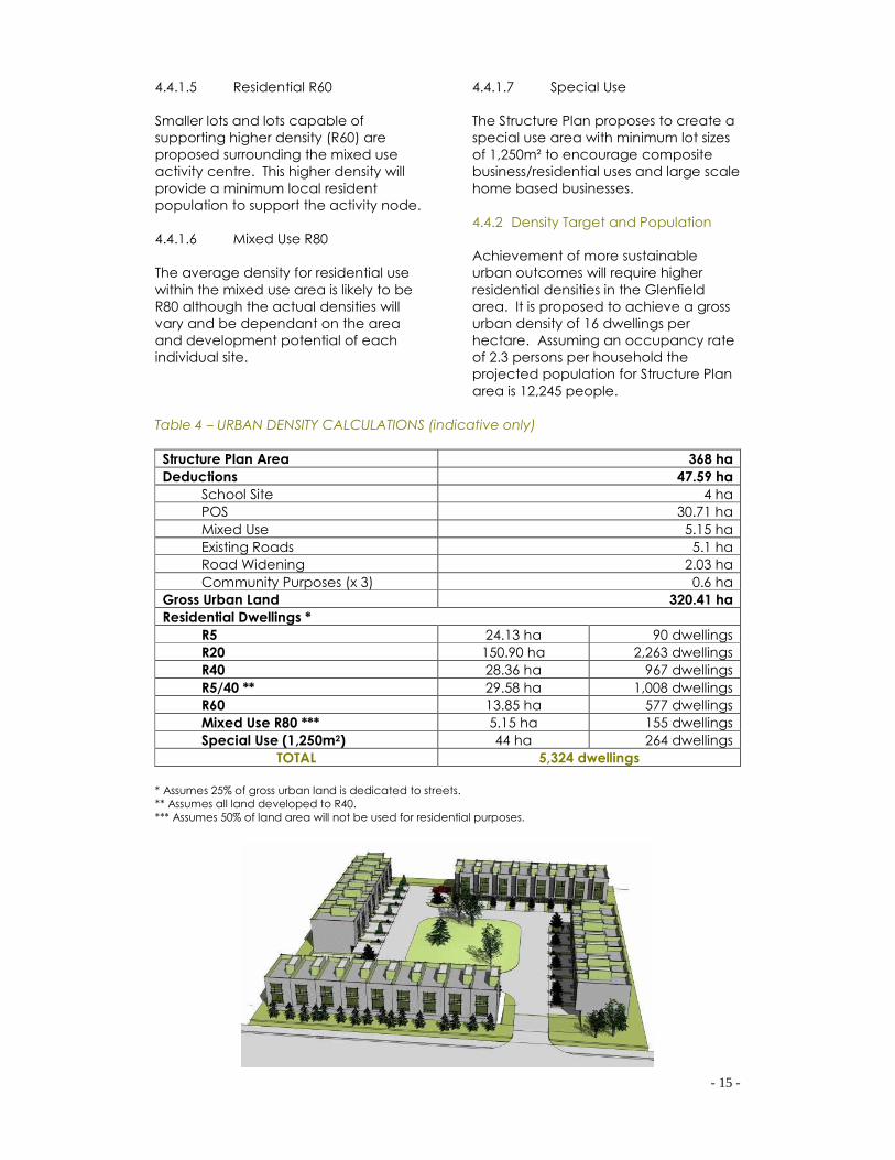
4.4.2 Density Target and Population
Achievement of more sustainable
urban outcomes will require higher
residential densities in the Glenfield
area. It is proposed to achieve a gross
urban density of 16 dwellings per
hectare. Assuming an occupancy rate
of 2.3 persons per household the
projected population for Structure Plan
area is 12,245 people.
Table 4 – URBAN DENSITY CALCULATIONS (indicative only)
Structure Plan Area 368 ha
Deductions 47.59 ha
School Site 4 ha
POS 30.71 ha
Mixed Use 5.15 ha
Existing Roads 5.1 ha
Road Widening 2.03 ha
Community Purposes (x 3) 0.6 ha
Gross Urban Land 320.41 ha
Residential Dwellings *
R5 24.13 ha 90 dwellings
R20 150.90 ha 2,263 dwellings
R40 28.36 ha 967 dwellings
R5/40 ** 29.58 ha 1,008 dwellings
R60 13.85 ha 577 dwellings
Mixed Use R80 *** 5.15 ha 155 dwellings
Special Use (1,250m2) 44 ha 264 dwellings
TOTAL 5,324 dwellings
* Assumes 25% of gross urban land is dedicated to streets.
** Assumes all land developed to R40.
*** Assumes 50% of land area will not be used for residential purposes.

- 16 -
4.4.3 Climate Responsive Design
The Structure Plan proposes a modified
grid pattern of streets predominantly on
north-south / east-west alignments. This
results in lots being able to be
orientated to take good advantage of
solar access.
4.5 PUBLIC PARKLAND
Through a focus on water sensitive
urban design, sustainability and
conservation, the Structure Plan aims to
primarily protect regionally significant
vegetation and integrate urban
stormwater management whilst
providing for a limited range of active
recreation opportunities.
The Structure Plan features three types
of public open space, being the linear
‘living stream’, the regionally significant
vegetation and the neighbourhood
park.
The City has concerns over the possible
number and size of local or
neighbourhood parks. The major issue is
the on-going cost to the City of
maintaining smaller areas of public
open space. It is therefore preferable
that the POS as shown on the Plan be
the only land areas that are provided
with cash-in-lieu contributions from
other land parcels.
There is currently a small Reserve 48448
on Macedonia Drive that was given up
for POS as part of a previous subdivision.
This Reserve is only 524m2 and there is
an opportunity for this land to be
converted to a freehold residential lot
and sold, with the proceeds to be
directed into POS development or land
acquisition.
The Structure Plan area is located
relatively close to the Indian Ocean to
the west and as such it is considered
that when this land is developed
(enabling greater public access) that
this foreshore and beach area will cater
for a number of recreational pursuits.
Tables 5 & 6 below are a POS schedule
that has been prepared for the purpose
of this Structure Plan. Whilst exact areas
of POS are likely to change in the future
as a result of detailed subdivision
designs, the principles that underlay the
POS will not change and the general
location of POS areas will also not
change significantly.

- 17 -
Table 5 – OVERALL PUBLIC OPEN SPACE SCHEDULE (indicative only)
Structure Plan Area 368 ha
Deductions
School Site
Mixed Use
Special Use
Existing Roads
Road Widening
Community Purposes (x 3)
60.88 ha
4 ha
5.15 ha
44 ha
5.1 ha
2.03 ha
0.6 ha
Gross Subdivisible Area 307.12 ha
POS (10%) 30.71 ha
POS Provided
Regionally Significant Vegetation 15.86 ha
Living Stream 12.78 ha
Neighbourhood Park 2.07 ha
Table 6 – PUBLIC OPEN SPACE SCHEDULE BY LOT (indicative only)
Regionally Significant Vegetation
Lot 146 Macedonia Drive
Lot 131 Alexander Drive
Lot 130 Alexander Drive
Lot 125 Alexander Drive
15.86 ha
1.89 ha
2.72 ha
4.91 ha
6.34 ha
Living Stream
Lot 35 Hagan Road
Lot 120 Alexander Drive
Lot 122 Alexander Drive
Lot 118 Alexander Drive
Lot 117 Okahoma Road
12.78 ha
2.38 ha
2.56 ha
2.27 ha
2.46 ha
3.16 ha
Neighbourhood Park
Lot 135 Alexander Drive
2.07 ha
2.07 ha

- 18 -
4.6 SCHOOLS
The Department of Education (DOE)
requires three primary schools in the
Glenfield/Drummond Cove/Sunset
Beach localities, based on population
numbers derived from the information
for the Northern Geraldton District
Structure Plan and the Geraldton
Region Plan.
One school site has already been
allocated in Sunset Beach (west of
Chapman Road) and the DOE advises
that this will serve a catchment of 1,570
lots.
The second primary school site would
be located north of Glenfield Drive and
west of Chapman Road and will serve
about 1,550 lots.
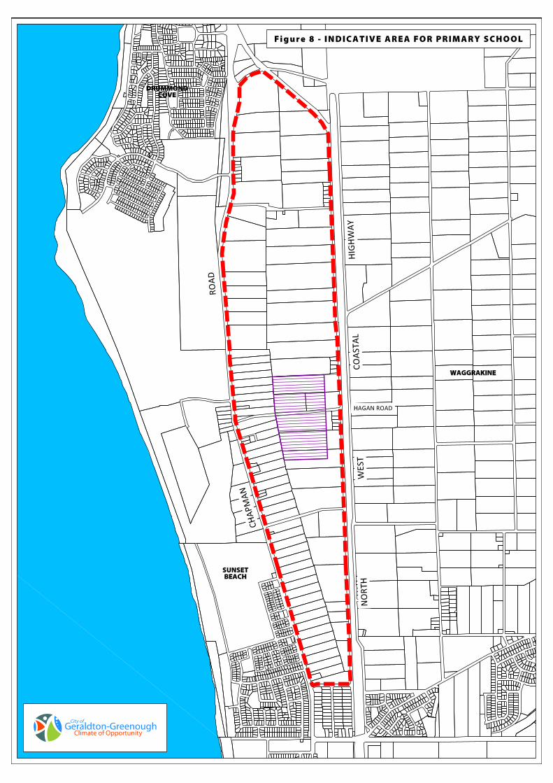
The DOE have advised that the third
primary school site will be required
around the central portion of Hagan
Road and east of Chapman Road and
will serve about 1,670 lots (Figure 8).
In its submission upon the Northern
Geraldton District Structure Plan the
DOE noted that it:
“would like the Hagan Road Primary
School site to be on the flat land half
way between Chapman Road and
North-West Coastal Highway. As for
the acquisition of this site, it would be
up to the landowners to approach
DET to initiate negotiations. We do
not necessarily have to wait to
acquire a site until we actually need
it for construction but the actual
timing would depend on the
availability of funding in the
Department's land acquisition
budget.”
Once a final site has been determined
and acquired by the DOE it will be
necessary to modify the Structure Plan
accordingly. The DOE has advised that
as the land in Glenfield is under multiple
ownership it would be prepared to
purchase a site from the open market
ahead of need, subject to the
availability of funds. The Department
would then be reimbursed by way of
pro rata contributions from affected
landowners as their subdivisions
proceed. Preliminary subdivisions in the
Glenfield locality have proceeded with
a condition of subdivisional approval
that payment be made to the DOE on
pro rata basis for the later acquisition of
a primary school site off the open
market.
Refer to Appendix C for the
Department of Education’s advice.
4.7 URBAN WATER MANAGEMENT
A district drainage analysis with regional
study options for stormwater drainage
has been undertaken to guide water
management in the Structure Plan area
(refer to Appendix D).
Best planning practice for stormwater
management involves integrating land
and water planning and implementing
water sensitive urban design. Water
sensitive urban design seeks to
incorporate stormwater drainage into
the urban fabric, in a new manner that
ensures the protection of surface and
ground water quality and enhances
opportunities for reuse of stormwater.
It is possible to incorporate the
principles of water sensitive urban
design within the Structure Plan area,
however there are major difficulties
coordinating drainage and siting of POS
locations due to the variation in
topography and soil types.
The other major issues in pre-planning a
major drainage system for the Structure
Plan area is the fragmented ownership,
size of the area and the unknown
sequence of development. The
combination of these factors will most
likely necessitate drainage systems of
micro or minor nature that will tend to
- 19 -
be more self-contained rather than
linked to a major system.
Developers should prepare Urban
Water Management Plans at the
detailed subdivision design stage to
ensure that appropriate water sensitive
design strategies are adhered to. There
is a presumption against fenced
drainage sumps for any subdivision
within the Structure Plan area.
4.8 UTILITIES
4.8.1 Water
The Water Corporation has indicated
that this area is presently serviced with
an adequate water supply although
some upgrading could be required. It
was suggested by the officers of the
Corporation that a staging of
development within Glenfield should be
considered as there is a need to try to
achieve a frontal approach with
respect to the provision of water in this
area. Due to the location of existing
services, it was suggested that the
development of lots in either the
northern or southern sections of the
Structure Plan could take place first with
infill toward the centre as later stages
occur. The market will largely dictate
that this approach is the most viable
however if landowners are prepared to
endure high up front costs for the
provision of services to non-frontal
development they should be permitted
to do so.
4.8.2 Sewerage
There will be a need to service the area
with a reticulated sewerage system as
residential subdivision occurs. There is
presently design and construction work
being undertaken with respect to the
provision of sewerage to the Sunset
Beach Estate subdivision. It would be
possible to service the northern section
of the Structure Plan area by way of
gravity feed to Chapman Road and
then pump the effluent to the
wastewater treatment plan at the
southern end of the Ocean Heights
Estate. The southern section of the
Structure Plan area could be serviced
relatively easily by way of gravity feed
direct to the existing mains in the Sunset
Beach subdivision.
The Water Corporation’s preference for
development in relation to the
sewerage, is that it proceed from the
south to the north. The preferred option
as suggested in this Report is to allow
development to occur either way with
only the possibility of the central section
of the Structure Plan area having some
difficulties in being serviced at this point
in time. Again, a frontal approach to
development was advocated by the
Water Corporation.
It is intended that all lots will be
ultimately connected to a reticulated
sewerage system. The Water
Corporation’s sewage planning has
included the Chapman
Road/Alexander drive R5 lots, however
‘house lot’ excisions and the Chapman
Road/Alexander R5 lots, given their
larger size, may not warrant connection
and effluent disposal should be in
accordance with the Country
Sewerage Policy and other relevant
legislation.
4.8.3 Power
With the recent introduction of the
Chapman Substation to the south of this
area, Western Power indicates that they
have capacity available in their system
sufficient to cater for full urban
development of Glenfield. One 27MVA
transformer is presently in place to
service the area however, there is
capacity within the substation to allow
for expansion to an additional two or
three such transformers which would
adequately cater for the future
densities of development.
The existing mains servicing the area
could easily be extended along
Alexander Road and Chapman Road
by an 11,000V service feeding into the
required underground residential
development system to all lots.
Padmounted substations within the
subdivisions will then supply the required
240 volts to the residential lots. Provision
within the subdivision may be required
to cater for power infrastructure
however, this will become a specific
requirement at the subdivision stage.

- 20 -
5 IMPLEMENTATION
Implementation of the Glenfield
Structure Plan presents some challenges
due primarily to the fragmented
ownership of the land. It is
recommended that the following
actions be undertaken to implement
the findings of the Structure Plan.
1. In conjunction with the Department
of Education, actively seek the
acquisition of a school site from the
open market. Once a school site
has been acquired amend the
Structure Plan accordingly.
2. Support subdivision provided that it
generally accords with the Structure
Plan and pays regard to:
• Major land use locations;
• Neighbourhood Connector and
Integrator road locations; and
• The need to ensure that adjoining
landowners are not
disadvantaged by any changes
to the Structure Plan.
3. Require the contribution towards
public open space at the time of all
initial subdivision applications. The
POS contribution shall be determined
according to the created residential
lot area and not the ‘balance’ land
area which shall be subject to further
POS contribution at the time of its
further subdivision.
5.1 ACTIVITY CENTRE PLANNING
Activity centres are major generators of
travel demand and have the physical
capacity to accommodate a greater
range and intensity of activity, therefore
the appropriate design is likely to make
a major contribution to creating a more
sustainable urban environment.
Appendix 2: Model Centre Framework
contained within the “State Planning
Policy, Activity Centres for Perth and
Peel” includes a detailed suite of
actions that should be undertaken in
the planning and design of activity
centres in order to create a more
sustainable urban environment.
These centre plans will be required prior
to any development or subdivision of
the Mix Use/Residential R80/Activity
Centre land, (with the exception of
2,000m2 lots fronting Chapman Road
which require a detailed area plan). As
part of the centre plans design
guidelines should be prepared to
address the following (where relevant):
• Height
• Plot Ratio
• Setbacks
• Car Parking
• Land uses and mix
• Heritage considerations
• Protection and enhancement of
views
• Pedestrian access and
movement
• Landscaping and streetscape
• Building materials and colours
• Public art and/or facilities
• Desired urban character.
- 21 -
5.2 SUBDIVISION GUIDE PLANS
To ensure that subdivision/development
proceeds in an orderly and proper
manner, and to avoid ad-hoc
subdivisional approvals, it is a
requirement that a subdivision guide
plan be prepared (where considered
warranted by the local government) to
show how an individuals’ lot design is
part of an overall plan for an area (with
the area defined by the local
government on a case-by-case basis).
Once these detailed plans have been
advertised to affected landowners (21
day period), and approved by the local
government, the Structure Plan will be
updated accordingly.
Guide plans should incorporate the
following:
• Additional access streets that
allow the urban fabric to respond
to change;
• Intersection treatments that
provide physical clues to assist in
legibility;
• The retention of landmarks,
habitats, significant vegetation
with environmental connectivity
where required;
• The location of public transport
facilities, cycleways and
pedestrian networks;
• The location of higher density
housing; and
• The provision of a School site
around the central section of
Hagan Road, following advice
from the Department of
Education on the purchase of a
site.
5.3 DETAILED AREA PLANNING
Detailed Area Plans (DAP’s) are
required for all the R5 lots along
Alexander Drive and any interim R5 lots
created abutting Chapman Road
(excluding lots in the Special Use area).
The DAP’s are required to address the
issue of interim access from Alexander
Drive, building envelopes, setbacks and
dual road frontage. In addition it
should clearly advise that Main Roads
WA will require Alexander Drive in the
future to become part of the future
North-West Coastal Highway and it will
not provide direct road access to
abutting residential properties.
For 2,000m2 lots fronting Chapman
Road in the residential area the DAP’s
will also need to show how future
intensification of the lots can be
achieved to an R40 standard including
access arrangements taking into
consideration future restrictions of
access onto Chapman Road.
5.4 INTERIM SUBDIVISION
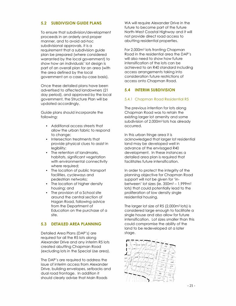
5.4.1 Chapman Road Residential R5
The previous intention for lots along
Chapman Road was to retain the
existing larger lot amenity and some
subdivision of 2,000m2 lots has already
occurred.
In this urban fringe area it is
acknowledged that larger lot residential
land may be developed well in
advance of the envisaged R40
development. In these instances a
detailed area plan is required that
facilitates future intensification.
In order to protect the integrity of the
planning objective for Chapman Road
support will not be given for ‘in-
between’ lot sizes (ie. 350m2 – 1,999m2
lots) that could potentially lead to the
proliferation of low density single
residential housing.
The larger lot size of R5 (2,000m2 lots) is
considered large enough to facilitate a
single house and also allow for future
intensification. Lot sizes smaller than this
could compromise the ability of the
land to be redeveloped at a later
stage.

- 22 -
5.4.2 Subdivision of Existing
Housing
The Structure Plan provides for the
retention of existing dwellings on larger
lots and the City will continue to support
the excision of ‘house lots’ without
requiring reticulated sewer connection
where those dwellings were existing or
had building approval prior to or on the
date of original adoption of the
Structure Plan (13 March 2002). The size
of the lot should have no further
subdivision potential itself (generally up
to 2,000m²), however, where
improvements are pertinent to the
dwelling, larger lot sizes may be
approved.
5.5 DEVELOPER CONTRIBUTIONS
The large physical size of the Glenfield
area and the predicted slow rate of
subdivision development could result in
difficulties in operating an effective
common cost fund. Due to problems
experienced with managing common
cost funds or costs associated with
guided development schemes (such as
Waggrakine), the City will minimise its
involvement in cost sharing. To this
extent the City will only be involved with
cost sharing arrangements relating to
public open space. The following
describes the rationale behind the
approach for common cost sharing in
relation to items traditionally considered
to form part of a common cost regime.
5.5.1 Drainage
In the past structure plans have
provided for large areas for district
drainage, accounting for all
landowners in the area. Under this
scenario redistribution of drainage
common costs is complex. As the dual
use of parks for recreation and
drainage is now part of contemporary
subdivision design, it would be almost
impossible to arrange any common
costs associated with drainage. If a
number of landowners jointly develop,
they can reach their own internal
agreement as to the size and location
of drainage requirements, alternatively
individual subdividers can provide
smaller areas to serve their individual
proposals. Either way the City need not
be involved in the cost equities of
district drainage facilities and
subdividers will be responsible for their
own drainage requirements at the time
of subdivision.
5.5.2 Major Roads
The Structure Plan shows a basic road
framework with the Neighbourhood
Connector and Integrator roads
forming the basis of the Structure Plan.
The new North-West Coastal Highway
alignment has down graded the
function of Chapman Road to that of
an Integrator A.
The City does not need to get involved
in the cost equities associated with
roads and individual subdividers will be
responsible for construction of internal
roads and contribution towards
upgrading of existing abutting roads.
Subdividers have the opportunity of
reclaiming costs for road construction
pursuant to the Planning and
Development Act.
5.5.3 Schools
The Department of Education & Training
has indicated that it is willing to
purchase a suitable site for a Primary
School from the open market and
ahead of need. The City is not required
to redistribute costs inequities as the
Department organises a pro rata
contribution from subdividers at the
time of subdivision.
- 23 -
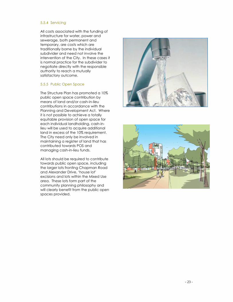
5.5.4 Servicing
All costs associated with the funding of
infrastructure for water, power and
sewerage, both permanent and
temporary, are costs which are
traditionally borne by the individual
subdivider and need not involve the
intervention of the City. In these cases it
is normal practice for the subdivider to
negotiate directly with the responsible
authority to reach a mutually
satisfactory outcome.
5.5.5 Public Open Space
The Structure Plan has promoted a 10%
public open space contribution by
means of land and/or cash-in-lieu
contributions in accordance with the
Planning and Development Act. Where
it is not possible to achieve a totally
equitable provision of open space for
each individual landholding, cash-in-
lieu will be used to acquire additional
land in excess of the 10% requirement.
The City need only be involved in
maintaining a register of land that has
contributed towards POS and
managing cash-in-lieu funds.
All lots should be required to contribute
towards public open space, including
the larger lots fronting Chapman Road
and Alexander Drive, ‘house lot’
excisions and lots within the Mixed Use
area. These lots form part of the
community planning philosophy and
will clearly benefit from the public open
spaces provided.
- 24 -
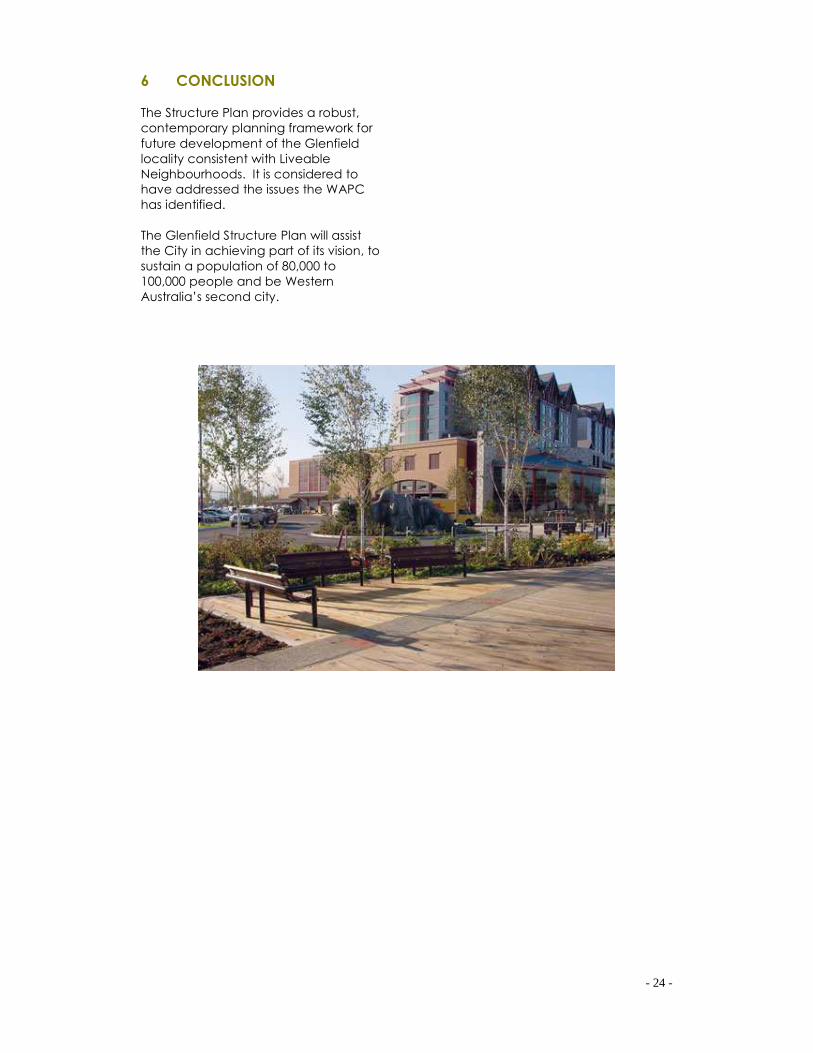
6 CONCLUSION
The Structure Plan provides a robust,
contemporary planning framework for
future development of the Glenfield
locality consistent with Liveable
Neighbourhoods. It is considered to
have addressed the issues the WAPC
has identified.
The Glenfield Structure Plan will assist
the City in achieving part of its vision, to
sustain a population of 80,000 to
100,000 people and be Western
Australia’s second city.


Appendix A – REGISTER OF ABORIGINAL SITES

Appendix B – MAIN ROADS WA ADVICE

Appendix C – DEPARTMENT OF EDUCATION ADVICE

Appendix D – STORMWATER AND DRAINAGE MANAGEMENT
PLAN
Glenfield Structure Plan Stormwater and Drainage Management Plan Department for Planning and Infrastructure
22 December 2008 Reference 36866 Revision 1
Connell Wagner Pty Ltd ABN 54 005 139 873 Unit 1 5 Chapman Road Geraldton Western Australia 6530 Australia Telephone: +61 8 9964 2764 Facsimile: +61 8 9964 2053 Email: [email protected] www.conwag.com
Document Control
Document ID: P:\8 - CITY OF GERALDTON GREENOUGH\GLENFIELD STRUCTRUE PLAN 2\FINAL\REP36866 FINAL.DOC
Rev No Date Revision Details Typist Author Verifier Approver
1 22 December 2008 Final RN RN MC LS
0 16 October 2008 Draft for comment RN RN MC LS
A person using Connell Wagner documents or data accepts the risk of: a) Using the documents or data in electronic form without requesting and checking them for accuracy against the original hard copy version. b) Using the documents or data for any purpose not agreed to in writing by Connell Wagner.

Department for Planning and Infrastructure Glenfield Structure Plan Stormwater and Drainage Management Plan
22 DECEMBER 2008 REVISION 1 PAGE i
Contents Section Page
1. Background and Objectives 1 1.1 Background 1 1.2 Objectives of the Study 1 1.3 Limitations of the study 1
2. Review of Current Plans 3 2.1 Draft revised Glenfield Structure Plan 3 2.2 Previous District Drainage Investigation for the GSP 3 2.3 Draft Northern Geraldton District Structure Plan 4 2.4 Approved and Proposed Subdivision Applications 4
3. Site Characteristics 5 3.1 Land Use 5 3.2 Climate 5 3.3 Site Geology 5 3.4 Surface Water and Waterways 5 3.5 Hydrogeology and Groundwater 6 3.6 Acid Sulphate Soils 6
4. Proposed Development and Impacts 7 4.1 Proposed Development 7 4.2 Potential Impacts 7
5. Water Management Objectives 8
6. Approaches to Stormwater Management 9
7. Analysis of Individual Neighbourhood Units 10 7.1 Special Use Zone 10 7.1.1 Recommendations 10 7.2 Southern and Southern Central Neighbourhoods 11 7.2.1 Recommendations 12 7.3 Central Neighbourhood 14 7.3.1 Recommendations 14 7.4 Northern Central Neighbourhood 15 7.4.1 Recommendations 15 7.5 Northern Neighbourhood 16 7.5.1 Recommendations 16
8. Summary of Recommendations 18 8.1 Special Use Zone - Drainage Management Area 1 18 8.2 Southern and Southern Central Neighbourhoods - Drainage Management Area 2, 3, 4, 5 18 8.3 Central Neighbourhood - Drainage Management Area 6, 7, 8 18 8.4 Northern Central Neighbourhood - Drainage Management Area 9 18 8.5 Northern Neighbourhood - Drainage Management Area 10 19
9. Stormwater Quality 20

Department for Planning and Infrastructure Glenfield Structure Plan Stormwater and Drainage Management Plan
22 DECEMBER 2008 REVISION 1 PAGE ii
10. Water Conservation 21
11. Groundwater Management 22
12. Wastewater Management 23
13. Conclusions 24
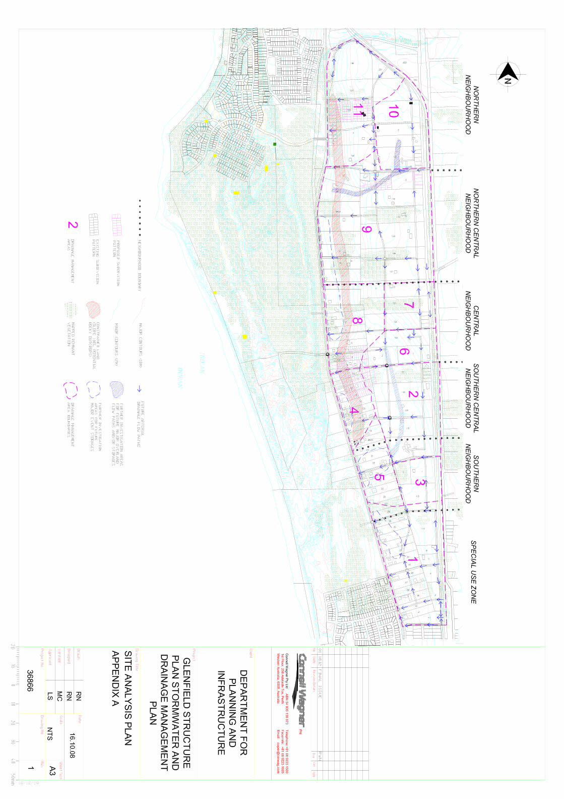
Appendix A – Site Analysis Plan 25
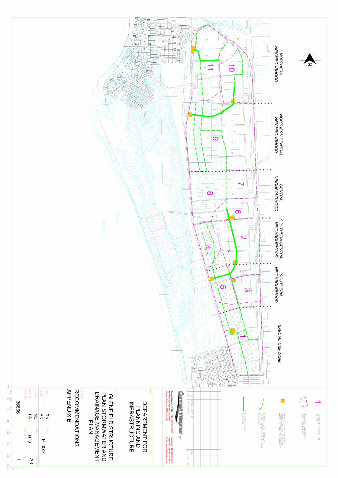
Appendix B – Recommendations 27
Appendix C – Study Brief 29
Department for Planning and Infrastructure Glenfield Structure Plan Stormwater and Drainage Management Plan
22 DECEMBER 2008 REVISION 1 PAGE 1
1. Background and Objectives
1.1 Background
A District Drainage Investigation was prepared in January 2008 by Connell Wagner for the City. The conclusions of the study were that water sensitive urban design within the study area is possible; however there are major difficulties in coordinating drainage and POS locations due to topography and soil types. Other difficulties identified were the fragmented ownership and unknown sequence of development. The investigation study suggested that the drainage systems will most likely be self-contained, rather than linked to any major district system, with the exception of one sub-catchment area, where there is potential to incorporate a drainage system into a linear POS network. At its meeting in March 2008 the Western Australian Planning Commission (WAPC) considered that while the Glenfield Structure Plan (GSP) stated there was a general presumption against fenced drainage sumps and agreement to integrate stormwater drainage that the approach of handling drainage on a small subdivision by subdivision basis would make a more integrated drainage system difficult to achieve. The Commission believes that a coordinated drainage system incorporating water sensitive urban design principles within the GSP area will not be achieved without an overall approach to stormwater management, which will involve investigating the integration of the location of POS areas with a drainage function and cooperation between all landowner within the GSP area and specifying in more detail how drainage requirements will be achieved. Connell Wagner was appointed by the WAPC to prepare an updated stormwater management plan in accordance with the study brief outlined in Appendix C.
1.2 Objectives of the Study
Best planning practice for stormwater management involves integrating land and water planning and implementing water sensitive urban design. An appropriate level of consideration needs to be given to the total water cycle at each stage of the planning system. The overall objective of the study, in accordance with the study brief, is to prepare a Stormwater and Drainage Management Plan for the Glenfield Structure Plan area that:
• Takes in to consideration the principles, objectives and requirements for total water cycle management as outlined in the draft Water Resources SPP, Liveable Neighbourhoods, and the Stormwater Management Manual for WA;
• reviews and builds on the District Drainage Investigation for the GSP area undertaken by Connell Wagner in January 2008;
• identifies appropriate methods to locate future stormwater attenuation areas integrated with Public Open Space (POS);
• seeks to maximise the opportunity to achieve integration of stormwater disposal with open space reserves and vegetation protection across the GSP area;
• provides a guide for the coordinated disposal of stormwater, across the GSP area.
1.3 Limitations of the study
This study addresses the treatment and disposal of runoff from future road reserves. It has been assumed that Council policy will address the control of stormwater for residential house construction through the building licensing process. It is assumed that post-development conditions will meet pre-development conditions through the use of soakwells and/or rain water tanks within the lots using council building controls. To meet pre-development conditions the City of Geraldton Greenough may need to update existing policy.

Department for Planning and Infrastructure Glenfield Structure Plan Stormwater and Drainage Management Plan
22 DECEMBER 2008 REVISION 1 PAGE 2
Recommendations on areas to be allocated for use as stormwater attenuation are based on estimates derived from simplified calculations. The areas are substantially smaller than Public Open Space requirements. Further investigations including development of a rainfall-runoff model are required to confirm assumptions. The recommendations of the study have been developed utilising the best available data. Soils information has been extracted from a 1:50,000 soil and landform inventory for the region. Remnant vegetation has been identified from mapping produced in 2005 which does not include detail on the quality of the mapped vegetation. Because of the limitations imposed by the accuracy of the data a probabilistic approach has been adopted to identifying potential constraints and opportunities present on the site. The recommendations should be primarily used for guiding further investigation.
Department for Planning and Infrastructure Glenfield Structure Plan Stormwater and Drainage Management Plan
22 DECEMBER 2008 REVISION 1 PAGE 3
2. Review of Current Plans
2.1 Draft revised Glenfield Structure Plan
A meeting was held with the CGG on 9 July 2008 to discuss the project and obtain a copy of the Draft Revised Glenfield Structure Plan (GSP). A copy of the plan was provided that incorporates the main change recommended in the Previous District Drainage Investigation. The draft revised GSP shows an area set aside for a linear POS network over the Eastern Portion of the Central and Southern Central Neighbourhoods. The purpose of the Glenfield Structure Plan is to provide a concept plan to guide future subdivision of the area. There are six neighbourhood cells proposed in the structure plan. The report proposes that the detailed design of each neighbourhood unit be considered individually. Detailed design of individual subdivisions would be subject to providing an overall plan for the area, the area being defined by local government on a case by case basis. Where contributions may be required, the GSP comments that their contribution areas may be defined by the neighbourhood units. The use of the planning unit provides scope to plan for cost sharing for Public Open Space and Infrastructure within each unit. The GSP proposes that each neighbourhood unit be self contained for provision of Public Open Space (POS). POS requirements are drawn from ‘Livable Neighbourhood’. Each neighbourhood planning unit is to contain one neighbourhood park of 3000-5000 square metres, a community purpose site of approximately 2000 square metres, and local parks to make up the difference. The GSP comments that neighbourhood parks be defined in the structure plan, and local parks to be determined at the detailed design stage. An overall density of R12.5 is proposed in the GSP as a reasonable estimate of the net density of the area. This includes an allowance of road reserves to occupy approximately 30% of the entire site area.
2.2 Previous District Drainage Investigation for the GSP
Connell Wagner undertook an investigation report of options for stormwater drainage for the structure plan area in January 2008. The report concluded that;
“It is possible to incorporate the principles of Water Sensitive Drainage Design within the study area. There are major difficulties however, coordinating drainage and siting of POS locations in the study area due to the variation in topography and soil types.
The other major issues in pre-planning a major drainage system for the Glenfield Structure Plan area are the fragmented ownership, size of the area and the unknown sequence of development. The combination of these factors will most likely necessitate drainage systems of micro or minor nature that will tend to be more self-contained rather than linked to a major system, with the possible exception of sub-catchment 2.
Sub-catchment 2 contains suitable soils, and topography for the provision of a major drainage system integrated in to a linear public open space network. The existing land use pattern is of an appropriate scale to incorporate an integrated land and water strategy over the entire sub-catchment.
It is recommended that a linear public open space network be further investigated at the detailed subdivision stage for land within sub-catchment 2 and that for the remainder of the site,

Department for Planning and Infrastructure Glenfield Structure Plan Stormwater and Drainage Management Plan
22 DECEMBER 2008 REVISION 1 PAGE 4
developers prepare Stormwater Management Plans at the detailed subdivision design stage to ensure that appropriate water sensitive design strategies are adhered to.”
2.3 Draft Northern Geraldton District Structure Plan
The GSP forms part of the Draft Northern Geraldton District Structure plan (NGDSP). The NGDSP makes several recommendations in relation to drainage. The majority of the GSP area drains to an area known as the ‘Rum Jungle’. This area is identified as future POS, Landscape and Recreation Reserves in the NGDSP. This will allow its existing drainage function to be maintained. Detailed recommendations outlined in the NGDSP on drainage include;
• a presumption against the use of fenced drainage sumps;
• where possible drainage should make use of swales and compensating basins located in POS
• buffers to surface water features 10m for drainage lines, and 30m for creeklines
2.4 Approved and Proposed Subdivision Applications
A number of subdivisions have been proposed for the Glenfield area. The majority of subdivision applications have been deferred or not approved pending modifications to be made to the GSP and the endorsement of a modified structure plan by City of Geraldton - Greenough and WAPC. The majority of approved subdivisions have occurred in the proposed R5 areas fronting Chapman Road and Alexander Drive. The approved subdivisions fix the location of some roads, however the limited number of approvals does not impose unreasonable restrictions on future planning. Three areas warrant further discussion; the proposed subdivision pattern over the seven lots fronting Chapman Road in the Central and Southern Central neighbourhood, lot 144 fronting Chapman Road in the Northern Neighbourhood, and former Lot 1 on D87978 (now lot 62 Macedonia Drive) in the Central Neighbourhood. These areas are discussed further in section 7 in the detailed analysis of individual neighbourhoods. In order to achieve a more integrated approach to the drainage issues it is important that decisions made on subdivisions approvals fit within an agreed overall drainage plan.

Department for Planning and Infrastructure Glenfield Structure Plan Stormwater and Drainage Management Plan
22 DECEMBER 2008 REVISION 1 PAGE 5
3. Site Characteristics
3.1 Land Use
The current land use of the site is a mixture of large lot residential, special use/home based commercial industry, and small scale agriculture. The majority of the catchment is grassland, being largely cleared of native vegetation except for a few pockets of remnant vegetation.
3.2 Climate
The climate of the area is Dry Warm Mediterranean, characterised by warm to hot, dry summers and mild, wet winters. The summer season is characterised by high average maximum daily temperatures and high net evaporation. Average daily maximum temperatures range from 19C in July to 32C in February. The average annual rainfall is approximately 475 mm, typically, most rainfall occurs during the months of May to August.
3.3 Site Geology
The majority of the site has been identified as the Tamala soil-landscape system. The landforms and soils associated with the study area are:
Teakle – Gently undulating sandplain with loose to soft, yellowish brown sand over yellow clayey sand over limestone. Teakle 1 – Crests and ridges comprise a shallow variant, limestone at less than 500mm Bookara 1 – Undulating rises and swales with loose, deep dark brown calcerous sands over limestone.
3.4 Surface Water and Waterways
Excess runoff from the site in its present condition has not formed any mappable channels or streams. The sandy soils in the area have high infiltration rates. Only larger events will result in runoff from the site. The site discharges to two surface water features, Dolby Creek and the low lying area to the east of the Quindalup dune system along Chapman Road. There is limited information available on the characteristics or significance of these two surface water features. The Department of Water provided some information from the report undertaken by Cardno BSD “Glenfield Beach Estate Soil and Vegetation Assessment” (Cardno BSD, April 2006, Unpublished) which is discussed below. The “Glenfield Beach Estate Soil and Vegetation Assessment” references the previous investigations for the Northern Geraldton District Structure Plan (Cardno BSD, 2005) noting that no specific studies exist that delineate the Dolby Creek channel or document its hydrologic or flooding characteristics. The creek is a blind system and discharges into a low lying swale area immediately east of the Quindalup Dune system which is known as the ‘Rum Jungle’. A portion of the GSP study area drains to Dolby’s Creek. The unknown flooding characteristics should be considered in developing management objectives. The “Glenfield Beach Estate Soil and Vegetation Assessment” also notes that there is no Wetland Mapping for the area and provides the recommendation that the vegetation of the 'Rum Jungle’ does not indicate that “it is part of an active waterway or considered to be a wetland. It does however

Department for Planning and Infrastructure Glenfield Structure Plan Stormwater and Drainage Management Plan
22 DECEMBER 2008 REVISION 1 PAGE 6
indicate that the site is likely to be part of a flood plain (that is likely to be) subjected to inundation and flooding during major storm events (in the order of 50 year or 100 year ARI events).” The ‘Rum Jungle’ area is considered locally significant and should be considered in developing goals and objectives for stormwater management within the study area. The study area is bounded on the upslope side by the North West Coastal Highway and service roads. The modified landscape provides a barrier to any potential flow from upslope. The southern section of the adjacent North West Coastal Highway is constructed on a fill embankment providing a barrier to upslope runoff. On the northern section there is a sag point approximately 100m north of Macedonia Drive. A small (375mm) culvert discharges to a long wide drainage swale within the road reserve. The combined affect of road levels, table drains, and sump/infiltration areas within the road reserve minimise the potential for upslope runoff contributing to the study area.
3.5 Hydrogeology and Groundwater
There is limited data available on the groundwater conditions across the study area. Senior hydrologist Midwest – Gascoyne Region for the Department of Water, Lazarus Leonhard has provided a best of knowledge assessment of groundwater conditions based upon the available data extrapolated across the site and general dynamics of coastal hydrogeology in a coastal/limestone environment. “The [Surface Water Level] SWL falls in a westerly direction from about 20 m below ground level (bgl) or 15 m AHD at the north eastern border to about 7 m bgl (3 m AHD) at the south western border. Groundwater will be unconfined and located within unconsolidated sand (probably synonymous with the Tamala Sand of the Perth coastal region. Regional groundwater flow will be in a general west - south-westerly direction. Groundwater levels are expected to fluctuate an average of 0.5 to 1 m. The greatest fluctuations would be expected in the western central portion of the GSP area, within the "saddle" east of the coastal dune - surface elevation high (approx. centred point 267447mE & 6823825mN). Groundwater levels in this area, situated between surface elevation highs, will respond quickly to groundwater recharge events forming a localised and temporal 'mound' of groundwater. The superficial formation would appear to be over 40 m in thickness and comprises about 20 m of sand overlying limestone. The thickness of sand will decrease in an easterly direction…The quality of groundwater would be expected to be fresh (500 mg/L) near the top of the aquifer. Groundwater salinity may increase with depth…The underlying sand will be highly transmissive…[and] Groundwater will be susceptible to the infiltration and movement of nutrients and agricultural/lawn chemicals.”
3.6 Acid Sulphate Soils
The north eastern portion of the GSP area has a high risk of associated acid sulphate soil. There is areas of medium risk present adjacent Chapman Road along the Western boundary of the structure plan area. The rest of the site is mapped as having low risk of potential acid sulphate soils. To determine the depths of potential acid sulphate soils drill sampling needs to be carried out. Investigations should be undertaken to below the lowest invert depth of any proposed sewer mains/pumping stations. Further assessment and management strategies can then be determined.
Department for Planning and Infrastructure Glenfield Structure Plan Stormwater and Drainage Management Plan
22 DECEMBER 2008 REVISION 1 PAGE 7
4. Proposed Development and Impacts
4.1 Proposed Development
The future development of the site consists of;
• a special use zone in the southern portion of the site;
• a commercial node fronting Chapman Road in the Central Neighbourhood;
• a proposed school site in the Central Neighbourhood (location to be confirmed) adjacent the commercial node;
• large lot residential (2000 square metre lots) fronting Chapman Road and Alexander Drive;
• and residential (550-800 square metre lots) for the remainder of the site. The study area is currently made up of 111 parcels of land with potentially a similar number of owners. The sequence and nature of development is difficult to anticipate given that the existing owners are many and varied and may choose not to develop their land further than they have to date. The fragmented ownership of the land provides a challenge for implementing a co-ordinated approach to future development of the area.
4.2 Potential Impacts
The proposed development has the potential to adversely impact on existing water quality and quantity throughout the site. Development will result in an increase in the proportion of impervious areas across the site. This in turn will lead to an increase in the volume of runoff that can enter water bodies during rainfall events. Increased impervious areas will also increase the potential for pollutants such as hydrocarbons, sediment, etc, being discharged to the local water bodies. In addition to impacts on the surface waters an increase in the proportion of impervious areas across the site may have an impact on groundwater levels.

Department for Planning and Infrastructure Glenfield Structure Plan Stormwater and Drainage Management Plan
22 DECEMBER 2008 REVISION 1 PAGE 8
5. Water Management Objectives
To take in to account the principles, objectives and requirements for total water cycle management as outlined in the draft Water Resources SPP, Better Urban Water Management 2008, Liveable Neighbourhoods, and the stormwater Management manual for WA, a set of water management objectives are provided in Table 5.1. These water management objectives are based on a literature review, providing objectives for stormwater management, water conservation, and groundwater management. Table 5.1 Water Management Objectives and Criteria
Objective Criteria Comments
Water balance and drain management (Stormwater Quantity)
To maintain the quantity of water to ensure protection of the ecosystem and environmental values in the area
1 in 1 year ARI discharges to the ‘Rum Jungle’ to match pre-
development flows.
To ensure that the quality of the modified runoff does not adversely affect the environmental values and meets all the statutory requirements
The post development flows shall be consistent with the pre development flows. For 1 year ARI the post development peak flows and volume shall be maintained relative to the pre development conditions.
Better Urban Water Management, WAPC 2008
Flood management for the entire catchment up to 1 in 100 year ARI event to match predevelopment flows
Better Urban Water Management, WAPC 2008
Stormwater Quality Minimise pollutants entering the waterways from stormwater runoff
Minimise runoff velocities and volumes to maximise retention times and allow for effective pollutant removal to achieve targets set
Excessive retention of stormwater to be avoided to enable riparian environmental flows to be maintained.
Maintain stormwater quality at pre development levels, or alternatively achieving at least:
• 80% reduction of total suspended solids • 60% reduction of total phosphorus • 45% reduction of total nitrogen • 70% reduction of gross pollutants
Better Urban Water Management, WAPC 2008
Comply with the requirements of the Department of Water Stormwater Management Manual for Western Australia
Soil and water erosion control
Identify areas susceptible to erosion and implement BMP’s
Areas with high slopes susceptible to erosion are identified in Appendix B
To achieve long-term Water Quality Objectives
No direct discharge of effluent, washwater or untreated stormwater to waterways
Water Conservation Potable water usage should be minimised where drinking water quality is not required
Better Urban Water Management, WAPC 2008
Protect potential public groundwater supplies from contamination

Department for Planning and Infrastructure Glenfield Structure Plan Stormwater and Drainage Management Plan
22 DECEMBER 2008 REVISION 1 PAGE 9
6. Approaches to Stormwater Management
To achieve the stormwater management objectives provided in section 5 a range of stormwater management tools are available. Stormwater management can be addressed through Source Controls, Conveyance Controls, and Discharge Controls. Overall management of stormwater systems can be aided through natural systems planning.
• Source Controls – Treating and disposing of excess stormwater at the source. May include measures such as retention, detention and infiltration systems.
• Conveyance Controls – Treating and disposing of stormwater during the conveyance of runoff from the source of generation to point of discharge. May include such measures as conventional kerb and gutter with a piped system, or a water sensitive urban design approach such as grass swales, bio-retention and natural channel designs.
• Discharge Controls – Treating and disposing of excess runoff at the point where water leaves the allotment, estate or catchment. Measures may include centralised stormwater retention/detention/infiltration facilities, and Gross pollutant traps.
• Natural Systems Planning – Natural systems planning is an approach to local area planning and neighbourhood design that recognises the essential hydrological and ecological functions of natural watercourses, floodplains, wetlands and remnant vegetation. Measures that can be incorporated include retaining natural drainage systems for trunk drainage and designing the neighbourhood features such as allotments, roads and public space around natural drainage systems, remnant vegetation, and contours.
The extent to which these measures and principles can be adopted will be limited by physical constraints of the site, the nature of the development proposed, and the sequence of development. The actual elements incorporated into any drainage strategy or subdivision design must therefore account for all local and regional environmental factors including climate, soils, groundwater, slope, vegetation, waterways, urban setting, and the existing pattern of land use. They should also be selected so as to minimise the life cycle cost of the system, particularly any ongoing maintenance/replacement costs. The GSP plan area is suited to utilising Natural Systems Planning to develop a trunk drainage system based on the natural contours of the site. The high infiltrative capacity of soils, make the site suitable for incorporating Source and Conveyance Controls that utilise infiltration, such as swales and bio-retention. To maintain pre-development discharges for low flows a piped network will also be required. Some discharge controls may be required at the bottom of each catchment.
Department for Planning and Infrastructure Glenfield Structure Plan Stormwater and Drainage Management Plan
22 DECEMBER 2008 REVISION 1 PAGE 10
7. Analysis of Individual Neighbourhood Units
For each neighbourhood unit the following was undertaken;
• Topography and soil landscape mapping was reviewed to identify the most suitable locations for combining POS with drainage.
• The distribution of remnant vegetation based on mapping in 2005 was overlayed on the soil and landscape mapping to identify possible locations for combining retention of existing remnant vegetation with POS and drainage.
• The topography and proposed road network was reviewed to identify potential post development flow paths.
• A Site Analysis Plan was prepared and discussed with the CGG and DPI (Appendix A)
• Assumptions were made regarding the future pattern of landuse and acceptable drainage solutions.
The following sections on each neighbourhood briefly describe the topography, soils, distribution of remnant vegetation, pre-development conditions, post development conditions, proposed road network, and surface water drainage for each neighbourhood. This is followed by recommendations for combining POS with drainage and remnant vegetation. Further recommendations regarding drainage, and for providing a more coordinated approach to stormwater management across the structure plan area are also provided. A graphical representation of the recommendations is included in Appendix B.
7.1 Special Use Zone
Drainage management area 1, Appendix B. Topography – The area consists of a gently sloping ridge, and moderate slopes extending from the ridge down to the gentle lower slopes. The lower slopes are widest at the northern end of the neighbourhood. Soils – Expected to be Teakle for the majority of the catchment with possibly Bookara 1 adjacent Chapman Road. Deeper sands are expected through the lower slopes and along the depression on the Northern end of the neighbourhood. Distribution of remnant vegetation – Remnant vegetation is shown covering parts of lots 29, 36, 38 fronting Chapman Road and lot 114 and 3 fronting Alexander Drive. Pre-development conditions – The subcatchment area is approximately 51 hectares. Lot sizes ranging from 4,400m2 to 7.1 hectares. Existing large scale home businesses are located in this area. Post development conditions – Mixed uses with a minimum lot size of 1,250m2. Proposed Road Network – Three East-West and two North-South neighbourhood connector roads are shown on the draft structure plan. Surface Water Drainage –Drainage is generally towards the North Western portion of the neighbourhood. It is difficult to assess wether or not this catchment is self contained, or if the catchment has an outlet and drains North along Chapman Road to the low lying area to the east of the Quindalup dune system along Chapman rd.
7.1.1 Recommendations
The Northern end of the neighbourhood is ideally suited to providing centralised drainage infrastructure. A shallow sided detention basin combined with POS in the northern portion of the area in the vicinity of lots 29,30,31,32 and 33 could be provided.
Department for Planning and Infrastructure Glenfield Structure Plan Stormwater and Drainage Management Plan
22 DECEMBER 2008 REVISION 1 PAGE 11
A small area of remnant vegetation with a local depression on Lot 29 may be suitable for a combined drainage and POS area. Sizing of land requirements for reduction of peak flows to meet pre-development conditions is subject to a high degree of unpredictability due to the range of possible variables. It is recommended that for reduction of peak flows to meet pre-development conditions 1-5% of the catchment area be allocated for stormwater attenuation. This is less than the POS allocation and will vary dependant on how much storage is provided in swales and other water sensitive urban design elements. An indicative location for siting the stormwater attenuation and infiltration area combined with POS is shown in Appendix B. To provide better coordination of stormwater management across the neighbourhood, North-South road linkages should be aligned with contours to provide better opportunities to manage stormwater at source. A revised internal road network has been developed over the drainage management area to provide an overland flow path to the centralised storage location. It is recommended that this internal road network incorporate a wider road reserve to accommodate an approximately five metre wide swale drain, such as the example given in Liveable Neighbourhoods, Figure 19.
7.2 Southern and Southern Central Neighbourhoods
Drainage management area 2, 3, 4 and 5. Topography – A ridge runs along the North Western side of the catchment. A wide depression extends from just north of Hagan Road to Okahoma Road, continuing on to Chapman Road. A slight ridge runs along the Southern end of the Southern Neighbourhood. Soils – Expected to be Teakle 1 through the ridge along the North Western side of the catchment and on the steeper slopes, Teakle through the wide depression and the mild slopes associated with the ridge at the Southern end, and potentially Bookara 1 adjacent Chapman Road. Distribution of remnant vegetation – Stands of trees and mapped remnant vegetation are located in the vicinity of the low point of the wide depression. Some mapped remnant vegetation exists on lot 2 fronting Okahoma Road and along the southern ridge over lots 27 and 28. Patches of remnant vegetation also occur on over lots 10, 11, 12, 121, 27, fronting Chapman Road. Pre-development conditions – Rear lots along Alexander Drive generally 4 to 7 hectares while the lots fronting Chapman Road are approximately 2 hectares with some 2000 square metre lots where subdivision has already taken place. Post development conditions – Standard residential development with a minimum lot size of 700m2 and 2,000m2 lots fronting Chapman Road and abutting Alexander Drive. POS is shown along the wide depression, and in the North Western corner of lot 118. Proposed Road Network –Three East-West and two North-South neighbourhood connector roads are shown on the draft structure plan. A portion of road reserve for a local access road has been dedicated on lot 12, fixing the future location of the local access roads for the Western section of the Southern Central Neighbourhood. Surface Water Drainage – The Eastern Section of the Southern and Southern Central Neighbourhoods drain towards Oakahoma Road. The western section of the Central Neighbourhood drains to Chapman
Department for Planning and Infrastructure Glenfield Structure Plan Stormwater and Drainage Management Plan
22 DECEMBER 2008 REVISION 1 PAGE 12
Road. The western portion of the Southern Neighbourhood is split by a ridge, some drainage being directed towards Oakahoma Road, while the majority of the area drains towards Chapman Road.
7.2.1 Recommendations
Discussion of the Southern and Southern Central Neighbourhoods is broken down in to four distinct drainage management areas;
• The eastern section of the Central Neighbourhood and including Lot 117 in the Southern Neighbourhood (Drainage management area 2)
• The remainder of the eastern section of the Southern Neighbourhood(Drainage management area 3)
• The western section of the Central Neighbourhood (Drainage management area 4), and
• The Western section of the Southern Neighbourhood (Drainage management area 5). The eastern section of the Central Neighbourhood and including Lot 117 in the Southern Neighbourhood- Drainage Management Area 2 The wide depression that extends from just north of Hagan Road to Oakahoma Road, continuing on to Chapman Road provides an opportunity for consideration of a planned major drainage system incorporated in the neighbourhood urban design. Liveable Neighbourhoods Figure 61: Example of Integrated Urban Water Management and Public Open Space – Cliff Sadlier Memorial Park, Daglish illustrates the application of these principles. The location of a combined drainage and POS area should take advantage of significant natural features such as mature stands of trees and remnant vegetation, and incorporate a series of informal shallow detention basins integrated with the topography and neighbourhood design To assist in achieving better stormwater management outcomes it is recommended that the distributor road network be modified to focus neighbourhood urban design on the proposed linear drainage/ POS network. Realigning the North South distributor road with the alignment of the natural drainage depression will provide for better integration of local street and lot layout with drainage / POS. It is recommended that planning mechanisms are incorporated in the structure plan, that require subdivision design to incorporate POS with drainage and where applicable vegetation protection, and to provide for connectivity for a major overland flow path following the low point of the natural wide depression. A 10-20m wide strip of land incorporating a living stream concept, bounded by local access roads, is required along the full length of the linear drainage / POS network to create an integrated corridor. It is recommended that for reduction of peak flows to meet pre-development conditions 1-5% of the catchment area be allocated to stormwater attenuation integrated with POS. An indicative corridor location is shown in Appendix B. The remainder of the eastern section of the Southern Neighbourhood- Drainage Management Area 3 Lots 115 fronting Alexander Drive and Lots 1 and 2 fronting Oakahoma Road drain in a North Westerly direction towards the corner of lot 2. Indicative grades are approximately 2.5 to 3 % across Lot 2 making it suitable for incorporating shallow detention basins. It is recommended that the potential for integrating POS, with drainage, on Lot 2 be further investigated. It is recommended that for reduction of peak flows to meet pre-development conditions 1-5% of the catchment area be allocated to stormwater attenuation areas integrated with POS. An indicative location is shown in Appendix B. The gentle grades and favourable soil conditions associated with the

Department for Planning and Infrastructure Glenfield Structure Plan Stormwater and Drainage Management Plan
22 DECEMBER 2008 REVISION 1 PAGE 13
topography provide many opportunities for integrating source and conveyance controls in subdivision design to reduce this requirement. It is recommended that the main North South distributor road shown on the GSP incorporates a widened road reserve to accommodate a 5m wide swale drain. The western section of the Southern Central Neighbourhood- Drainage Management Area 4 The most suitable location for a centralised storage location is the natural low lying area fronting Chapman Road in the vicinity of lots 13, 14, 125, 130, and 124. Mapped remnant vegetation exists on Lots 10, 11, 12. Existing structures on Lot 14, 125, and 130 limit the area available for combination of remnant vegetation with POS. The location of a proposed North South local access road has been defined and is shown over lots 10, 11, 12, and 13 on the draft GSP. The North South local access road shown generally follows the contour, however steep cross slopes will result in poor urban form and increased erosion risk. It is recommended that the road network be modified to provide North South access roads located at the top and bottom of the steep slopes, and that these roads incorporate a 5m wide central drainage swale. It is recommended that each lot control drainage through suitable source and conveyance controls and that any additional land requirements for stormwater management be addressed at the subdivision scale. Alternatively excess stormwater could be conveyed via drainage swales to the Chapman Road reserve area in the vicinity of abutting lots 12, 13, 14, 125, 130, and 124. It is recommended that for reduction of peak flows to meet pre-development conditions 1-5% of the catchment area be allocated to stormwater attenuation areas integrated with POS. An indicative swale drainage location is shown in Appendix B. The Western section of the Southern Neighbourhood - Drainage Management Area 5 The most suitable location for a centralised drainage management area is the northern end of the Southern Neighbourhood. This area is an extension of the wide depression that runs through the eastern part of the Southern Central Neighbourhood and extends through to Chapman Road. There is a small area of overlap of remnant vegetation with the wide depression on Lot 23. However, existing structures on Lot 23 limit the area available for inclusion in POS. It is recommended that for reduction of peak flows to meet pre-development conditions 1-5% of the catchment area be allocated to stormwater attenuation areas integrated with POS. An indicative location is shown in Appendix B. A continuation of the living stream corridor along the natural low lying land that runs through the eastern part of the Southern Central Neighbourhood is recommended. The living stream corridor adjacent a local road could be provided as a 10-20m wide strip of land incorporating drainage and POS functions is recommended. The anticipated initial sequence of development is for 2000 square metre lots fronting Chapman Road to be subdivided off the parent properties. To achieve a more coordinated approach to stormwater management it is recommended that planning mechanisms are incorporated in the structure plan, that require dedication of a widened road reserve, with a central drainage swale as shown in Appendix B, over lots 17, 18, 9000, 20, 21, 22, 23, 24, 25, 26, 27 and 28 fronting Chapman Road. A suitable treatment is shown in Liveable Neighbourhoods, Figure 19.
Department for Planning and Infrastructure Glenfield Structure Plan Stormwater and Drainage Management Plan
22 DECEMBER 2008 REVISION 1 PAGE 14
The natural topography of the land should be utilised to drain the road swale drains to the living stream corridor along the low point of the drainage management area.
7.3 Central Neighbourhood
Drainage Management Area 6, 7 and 8 Topography – A ridge terminates at the centre of the neighbourhood. The South Eastern section of the Neighbourhood slopes gently to the South West. The remainder of the neighbourhood is characterised by an upper sand plain that moderately slopes to the west down to a gently undulating sandplain along the frontage to Chapman Road. Soils – Expected to be Teakle through the upper sandplain and middle slopes. Teakle 1 through the section of the ridge and potentially extending to some areas of the middle slopes, and a combination of Bookara 1 and Teakle through the lower sandplain adjacent Chapman Road. Distribution of remnant vegetation – A significant mapped remnant vegetation link is shown on lot 125 fronting Alexander Drive. Some mapped remnant vegetation exists on Lot 1 2, 3, 4, 7, and 8 fronting Chapman Road. Pre-development conditions – Rear lots along Alexander Drive generally 4 to 7 hectares while the lots fronting Chapman Road range from 2 to 4 hectares. Post development conditions – The area fronting Chapman Road has been identified as a potential neighbourhood centre with higher density mixed use development. The central area of the neighbourhood has been identified as a potential school site. The remainder of the neighbourhood is Standard residential development. Proposed Road Network –Two East-West and three North-South neighbourhood connector roads are shown on the draft structure plan. Surface Water Drainage – The South Eastern Section of the Neighbourhood drains to the wide depression that runs through the Eastern part of the Southern Central Neighbourhood. The remainder of the catchment drains towards Chapman Road.
7.3.1 Recommendations
The South Eastern section of the neighbourhood (Drainage Management Area 6) can be treated in a similar fashion to the Eastern part of the Southern Central Neighbourhood, with inclusion of a living stream corridor incorporated in a combination of POS and Road Reserves. The North Eastern section of the neighbourhood (Drainage Management area 7) displays good site attributes for incorporating water sensitive design elements at a subdivision scale. Larger lots may be suitable for incorporating drainage elements in a POS network. Development should be controlled such that the sequence of development on larger lots does not diminish any opportunities for combining POS, with drainage at a subdivision scale. It is recommended that the North South local access road running between Drainage Management Area 6 and 7 incorporate a widened road reserve to provide an overland flow path to the living stream corridor. A treatment such as the example given in Liveable Neighbourhoods, Figure 19 is recommended. The most suitable area for a centralised drainage management area for the remainder of the neighbourhood (Drainage Management area 8) is in the vicinity of the area fronting Chapman Road on lots 5, 4, 3, 2, 1, and 10. There is an overlap with mapped remnant vegetation on lots 1, 2, 3 and 4. It is
Department for Planning and Infrastructure Glenfield Structure Plan Stormwater and Drainage Management Plan
22 DECEMBER 2008 REVISION 1 PAGE 15
recommended that this area be considered for further investigation for integration of drainage and POS within the proposed mixed use centre. It is recommended that for reduction of peak flows to meet pre-development conditions 1-5% of the catchment area be allocated to stormwater attenuation areas integrated with POS. The area fronting Chapman Road, north of Hagan Road, in this neighbourhood has been proposed as a neighbourhood mixed use centre with a higher density of development. Drainage for this area will be subject to future detail design. Suitable source control methods could be integrated in to the design of streetscape elements. To achieve the objectives outlined for water quality management more technical water sensitive design elements requiring minimal land area could be utilised.
7.4 Northern Central Neighbourhood
Drainage Management Area 9 Topography – Gently undulating sand plain through the upper section of the catchment. The land moderately slopes to the west from the edge of the upper sand plain to a gently undulating sandplain along the frontage to Chapman Road. Soils – Expected to be Teakle through the upper sand plain and middle slopes and a combination of Bookara 1 and Teakle through the lower sandplain adjacent Chapman Road. Distribution of remnant Vegetation – Mapping indicates several large areas of remnant vegetation in this neighbourhood on lots 28, 131,130. Pre development conditions- Lot sizes ranging from 3 to 10 hectares, with some smaller residential lots that have been created as part of subdivision of lot 2 fronting Macedonia Drive. A small area of POS has been dedicated as part of this subdivision. Post development conditions – Standard residential development with a minimum lot size of 700m2 and 2,000m2 lots fronting Chapman Road and abutting Alexander Drive. An area of POS has been indicated on lot 2 fronting Macedonia Drive incorporating the existing POS. Proposed Road Network - Two East-West and three North-South neighbourhood connector roads are shown on the draft structure plan. Surface Water Drainage – The neighbourhood generally drains in a Westerly direction towards Chapman Road and is considered as one drainage management area (9).
7.4.1 Recommendations
The low lying area fronting Chapman Road would be the most suitable location for centralised drainage management that could be incorporated with POS. There are no specific areas which overlap with remnant vegetation. The majority of the site is suitable for source controls such as infiltration trenches and soakwells, and conveyance controls such as swales and bioretention systems. Larger lots may be suitable for incorporating drainage elements such as road swales as part of the local access road system and a POS network incorporating stormwater attenuation areas. Development should be controlled such that the sequence of development on larger lots does not diminish any opportunities for combining POS, with remnant vegetation and drainage at a subdivision scale. Sizing of land areas for inclusion of drainage in POS is subject to a high degree of variability due to the range of source and conveyance controls that could be utilised to treat and dispose of stormwater throughout the site. It is recommended that for reduction of peak flows to meet pre-development

Department for Planning and Infrastructure Glenfield Structure Plan Stormwater and Drainage Management Plan
22 DECEMBER 2008 REVISION 1 PAGE 16
conditions 1-5% of the catchment area be allocated to stormwater attenuation areas integrated with POS. Indicative locations are shown in Appendix B. At the Northern End of the neighbourhood an existing natural swale traverses Macedonia Drive, and continues over lots 2, 131, and 52. Consideration should be given to utilising the swale to create a living stream corridor, incorporated where possible adjacent internal subdivision road reserves and remnant vegetation area with POS. A minimum width of 10-20m is recommended. It is recommended that the proposed pattern of subdivision, and future POS shown on Lot 2 fronting Macedonia Drive be modified to incorporate a 10-20m wide living stream corridor, and POS location to accommodate the natural low point as shown in Appendix B. The anticipated initial sequence of development is for 2000 square metre lots fronting Chapman Road to be subdivided off the parent properties. It is recommended that planning mechanisms are incorporated in the structure plan, that require dedication of a widened road reserve to incorporate a 5m wide drainage swale, at the base of the steeper slope over lots 11, 12, 13, 2, 1, 9843, 52, and 51. It is recommended that a similar treatment be provided at the top of the steep slope to reduce erosion risk. The natural topography of the land should be utilised to drain the swale drains to the living stream corridor.
7.5 Northern Neighbourhood
Drainage Management Area 10 and 11 Topography – Gently undulating sandplain through the Eastern section of the neighbourhood, with a wide shallow depression crossing over lots 1, 2, and 133 fronting Alexander drive. The western section of the neighbourhood is gently sloping to the West with some moderate slopes along the frontage to Chapman Road. Soils – Expected to be Teakle through the majority of the catchment. Distribution of Remnant Vegetation - Mapped remnant vegetation is shown on lot 146, 144, 143 and along Dolby’s Creek. Pre-development conditions – Lot sizes generally ranging from 2,000m2 to 9 hectares. Post development conditions – Standard residential development with a minimum lot size of 700m2 and 2,000m2 lots fronting Chapman Road and abutting Alexander Drive. Remnant Vegetation - An area of remnant vegetation occurs on Lot 146. Proposed Road Network – Two East-West distributor roads; one running the full width of the neighbourhood, the other terminating half way. Two North -South distributor roads. The boundary of the neighbourhood is defined by a distributor road shown following the alignment of Dolby’s Creek to the North West Coastal Highway. Surface Water Drainage – The upper section of the neighbourhood drains via the shallow depression to the adjoining neighbourhood over Macedonia Drive. A small section drains to Dolby’s Creek while the remainder drains Westerly to Chapman Road and the outlet of Dolby’s Creek.
7.5.1 Recommendations
Lot sizes are large, and the landform and soils are suitable for source controls such as infiltration trenches and soakwells, and conveyance controls such as swales and bioretention systems.
Department for Planning and Infrastructure Glenfield Structure Plan Stormwater and Drainage Management Plan
22 DECEMBER 2008 REVISION 1 PAGE 17
Development should be controlled such that the sequence of development does not diminish any opportunities for combining POS, with drainage requirements. Sizing of land areas for inclusion of drainage in POS is subject to a high degree of variability due to the range of source and conveyance controls that could be utilised to treat and dispose of stormwater throughout the site. It is recommended that for reduction of peak flows to meet pre-development conditions 1-5% of the catchment area be allocated to stormwater attenuation areas integrated with POS. There is an area of remnant vegetation on the north east portion of lot 146.There are no areas of remnant vegetation shown in the eastern section of the neighbourhood i.e. Drainage Management Area 10.
In drainage management area 10 a wide shallow depression occurs on lot 139 and provides a good opportunity for incorporating drainage elements into a living stream/POS corridor. Consideration should be given to utilising the natural low point of the depression to create the living stream corridor, to link into the northern end of drainage management area 9 and through to Chapman Road. A minimum width of 10-20m is recommended. Indicative location is shown in Appendix B. The Western section of the neighbourhood (Drainage Management area 11) does not have any quality remnant vegetation. No areas have been identified as having substantially better attributes for location of POS with drainage. To provide a flow path to Chapman Road, an East West drainage link incorporating a living stream corridor is recommended adjacent a local access road reserve near lot 143 as shown in Appendix B. The corridor could from part of POS. A minimum width of 10-20m is recommended. To provide better coordination of stormwater management across the neighbourhood a drainage swale network has been developed as shown in Appendix B. In these areas a widened road reserve is required to accommodate a central swale drain, such as the example given in Liveable Neighbourhoods, Figure 19. The natural topography of the land should be utilised to drain the swale drains to the living stream corridor. Along the frontage with Dolby’s creek a buffer of 30m is recommended to preserve remnant riparian vegetation, in accordance with the drainage management recommendations of the NGDSP.
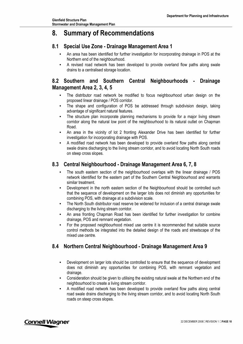
Department for Planning and Infrastructure Glenfield Structure Plan Stormwater and Drainage Management Plan
22 DECEMBER 2008 REVISION 1 PAGE 18
8. Summary of Recommendations
8.1 Special Use Zone - Drainage Management Area 1
• An area has been identified for further investigation for incorporating drainage in POS at the Northern end of the neighbourhood.
• A revised road network has been developed to provide overland flow paths along swale drains to a centralised storage location.
8.2 Southern and Southern Central Neighbourhoods - Drainage Management Area 2, 3, 4, 5
• The distributor road network be modified to focus neighbourhood urban design on the proposed linear drainage / POS corridor.
• The shape and configuration of POS be addressed through subdivision design, taking advantage of significant natural features.
• The structure plan incorporate planning mechanisms to provide for a major living stream corridor along the natural low point of the neighbourhood to its natural outlet on Chapman Road.
• An area in the vicinity of lot 2 fronting Alexander Drive has been identified for further investigation for incorporating drainage with POS.
• A modified road network has been developed to provide overland flow paths along central swale drains discharging to the living stream corridor, and to avoid locating North South roads on steep cross slopes.
8.3 Central Neighbourhood - Drainage Management Area 6, 7, 8
• The south eastern section of the neighbourhood overlaps with the linear drainage / POS network identified for the eastern part of the Southern Central Neighbourhood and warrants similar treatment.
• Development in the north eastern section of the Neighbourhood should be controlled such that the sequence of development on the larger lots does not diminish any opportunities for combining POS, with drainage at a subdivision scale.
• The North South distributor road reserve be widened for inclusion of a central drainage swale discharging to the living stream corridor.
• An area fronting Chapman Road has been identified for further investigation for combine drainage, POS and remnant vegetation.
• For the proposed neighbourhood mixed use centre it is recommended that suitable source control methods be integrated into the detailed design of the roads and streetscape of the mixed use centre.
8.4 Northern Central Neighbourhood - Drainage Management Area 9
• Development on larger lots should be controlled to ensure that the sequence of development does not diminish any opportunities for combining POS, with remnant vegetation and drainage.
• Consideration should be given to utilising the existing natural swale at the Northern end of the neighbourhood to create a living stream corridor.
• A modified road network has been developed to provide overland flow paths along central road swale drains discharging to the living stream corridor, and to avoid locating North South roads on steep cross slopes.

Department for Planning and Infrastructure Glenfield Structure Plan Stormwater and Drainage Management Plan
22 DECEMBER 2008 REVISION 1 PAGE 19
8.5 Northern Neighbourhood - Drainage Management Area 10
• Development should be controlled to ensure that the sequence of development does not diminish any opportunities for combining POS with drainage.
• An opportunity exists to site drainage elements along the widened road reserve adjacent lots 139 and 143.
• The wide natural shallow depression in the eastern section of the neighbourhood provides a good opportunity for creating a living stream corridor.
• An east west drainage link incorporating a living stream corridor is proposed over the western part of the neighbourhood.
• A modified road network has been developed to provide overland flow paths along road swale drains discharging to a living stream corridor
• Along the frontage with Dolby’s creek a buffer of 30m is recommended to preserve remnant riparian vegetation and floodway functions.
Department for Planning and Infrastructure Glenfield Structure Plan Stormwater and Drainage Management Plan
22 DECEMBER 2008 REVISION 1 PAGE 20
9. Stormwater Quality
The Stormwater Management manual for Western Australia provides information on the pollutant removal efficiencies for bio-retention swales and basins with varying depths of ponding (pg104-105). Little data is available regarding the performance of treatment systems in Western Australia, particularly in the Geraldton area. Data is provided as an indicative guide only, based on eastern states research with different hydrologic conditions. MUSIC modelling and calibration to the hydrologic conditions of the area are required to provide more accurate assessment. The data indicates that to achieve the treatment targets for total suspended solids, total phosphorous, and total nitrogen, the surface area of swales and basins should be in the order of 1 to 2% of the impervious catchment area. These requirements can be accommodated in the areas suggested as part of living streams, swales, and small detention basins. It is recognised that there are some locations which will be directly piped and discharged to the ‘Rum Jungle’ based on the structure plan proposed. It is recommended that as a minimum a Gross Pollutant Trap be provided at these locations. Treatment for reduction of nutrients can be addressed by offsetting treatment with higher treatment in other areas.
Department for Planning and Infrastructure Glenfield Structure Plan Stormwater and Drainage Management Plan
22 DECEMBER 2008 REVISION 1 PAGE 21
10. Water Conservation
Water Conservation is identified as one of the management objectives. Under sustainability practices a local water resource is a potential source of water supply. For the study there are three potential local water sources that could be used to supplement the scheme supply, Rainwater, Surface Water, and Groundwater. It is recommended that potable water demand be minimised across the GSP area by incorporating alternative water supplies where possible. Rainwater: A supplementary supply from rainwater tanks could be utilised on the lot scale and would have multiple benefits for stormwater management and demand reduction. However it is noted for the area that it has low rainfall with long dry spells. The cost effectiveness of rainwater tanks would be lower compared to other areas of the state. Surface Water: There are no existing Local Surface Water Storages, however artificial surface water storages may be proposed as part of future development. The area is highly pervious and to achieve this would require utilisation of impervious liners. Due to the low and inconsistent rainfall in the area any ponded water body should be reviewed for long term water quality management and to avoid the creation of stagnant water bodies. Due to the low and infrequent rainfall, and soil types of the catchment direct collection and reuse in artificial surface water storages is not recommended. Groundwater: As an alternative to surface water storage and reuse, localised aquifer recharge combined with groundwater extraction may be preferable for this area. This would create a more indirect reuse scheme which utilises the natural attributes of the area i.e. using the aquifer for storage/reuse. Larger bores for irrigation of POS are encouraged to supplement scheme water. Larger volume bores should be tested (down hole resistivity) to ensure that the quality of groundwater at depth is appropriate for the intended use. Domestic bores are a viable option for the GSP area and should be encouraged. Bores should be kept as shallow as possible to avoid intersecting saline groundwater.

Department for Planning and Infrastructure Glenfield Structure Plan Stormwater and Drainage Management Plan
22 DECEMBER 2008 REVISION 1 PAGE 22
11. Groundwater Management
The proposed land use scenario will not require the groundwater level to be controlled and/or fill to be imported to maintain minimum separation distances to the groundwater level where reticulated sewer is provided. The expected high infiltration rates of the site will provide a potential pathway for nutrients and contaminants to be transported directly to the groundwater. It is recommended that all stormwater be provided with adequate pre-treatment prior to infiltration to protect groundwater quality. Lazarus Leonhard - Senior hydrologist Midwest – Gascoyne Region for the Department of Water has recommended the following groundwater monitoring strategy; “Groundwater monitoring strategies should include a minimum of 2 piezometers (observation bores) situated mid north east and south east along the eastern GSP boundary. These bores will provide a continuous base line data set comprising salinity (measured by electrical conductivity or EC) and SWL. It is considered that a minimum of 4 piezometers along the western border would be appropriate.” In addition to the suggested groundwater monitoring strategy including a minimum of six monitoring bores along the eastern and western boundaries of the structure plan area, an additional monitoring bore in the western central portion of the GSP area, within the saddle east of the coastal dune is recommended.
Department for Planning and Infrastructure Glenfield Structure Plan Stormwater and Drainage Management Plan
22 DECEMBER 2008 REVISION 1 PAGE 23
12. Wastewater Management
The majority of the GSP area will require servicing with reticulated sewer. Lots greater than 2000 square metres, in particular those fronting Chapman Road, may require additional controls and/or filling to comply with Department of Health Guidelines for on site sewerage disposal. It is recommended that groundwater levels be confirmed along the Western Boundary of the GSP area to confirm adequate separation distances are available.
Department for Planning and Infrastructure Glenfield Structure Plan Stormwater and Drainage Management Plan
22 DECEMBER 2008 REVISION 1 PAGE 24
13. Conclusions
The previous district drainage investigation concluded that drainage systems would most likely be self contained, rather than linked to any major district system, with the exception of a linear POS network proposed over the Eastern portion of the Southern Central neighbourhood. This report investigated the opportunities for combining POS with drainage and mapped remnant vegetation for each neighbourhood planning unit identified in the draft revised GSP. Recommendations have also been made for providing a more coordinated approach to stormwater management across the structure plan area. Areas have been identified to promote the retention of existing drainage functions, and combining these with the retention of remnant vegetation where possible. Field investigations are required to confirm assumptions regarding soil types, topography and vegetation. Where areas have been identified for further investigation the overall requirements of POS need to be considered. The designation of POS will be guided by other factors external to drainage considerations such as provision of useable POS readily accessible to residents, and protection of natural areas. The fragmented ownership of lots provides a challenge for coordinating stormwater disposal across the structure plan area. Modifications to the road network have been suggested to provide a more coordinated approach to stormwater management. The network of distributor roads can be utilised to provide continuity in drainage management across lot boundaries, and as an overall arterial drainage network to accommodate major events. Further modelling will be required if a development contribution plan is to be developed. Due to the low rainfall, high porosity of the soil and good access to the superficial aquifer, a suggested form of recycling and reuse is to maximise recharge of the aquifer and provide groundwater bores for reuse. Surface water retention may not be as cost effective as indirect reuse via the groundwater aquifer. The individual design of subdivisions will need to take in to consideration the recommendations provided, and incorporate their own source controls and conveyance controls to achieve the stormwater management objectives outlined in Section 5. Prior to approval of subdivision layouts applicants should demonstrate that the design principles incorporated in the Stormwater Management Manual for WA have been included and that the objectives outlined in section 5 have been addressed. Compliance should be addressed on a neighbourhood by neighbourhood basis.

Department for Planning and Infrastructure Glenfield Structure Plan Stormwater and Drainage Management Plan
22 DECEMBER 2008 REVISION 1 PAGE 25
Appendix A – Site Analysis Plan

Department for Planning and Infrastructure Glenfield Structure Plan Stormwater and Drainage Management Plan
22 DECEMBER 2008 REVISION 1 PAGE 26

Department for Planning and Infrastructure Glenfield Structure Plan Stormwater and Drainage Management Plan
22 DECEMBER 2008 REVISION 1 PAGE 27
Appendix B – Recommendations

Department for Planning and Infrastructure Glenfield Structure Plan Stormwater and Drainage Management Plan
22 DECEMBER 2008 REVISION 1 PAGE 28

Department for Planning and Infrastructure Glenfield Structure Plan Stormwater and Drainage Management Plan
22 DECEMBER 2008 REVISION 1 PAGE 29
Appendix C – Study Brief

Department for Planning and Infrastructure Glenfield Structure Plan Stormwater and Drainage Management Plan
22 DECEMBER 2008 REVISION 1 PAGE 30