glass and mechanical strength - f.h. brundle
TRANSCRIPT
CONTENTS INTRODUCTION REGULATIONS DESIGN PRODUCTOVERVIEW
WINDLOADING
CALCULATIONPROGRAMS
PLANAR
Glass and Mechanical StrengthTechnical Bulletin
CONTENTS INTRODUCTION REGULATIONS DESIGN PRODUCTOVERVIEW
WINDLOADING
CALCULATIONPROGRAMS
PLANAR
ContentsIntroduction .. . . . . . . . . . . . . . . . . . . . . . . . . . . . . . . . . Page 3
Regulations and Standards .. . . . . . . . Page 4
Design and Applications .. . . . . . Page 5 –16
CONTENTS INTRODUCTION REGULATIONS DESIGN PRODUCTOVERVIEW
WINDLOADING
CALCULATIONPROGRAMS
PLANAR
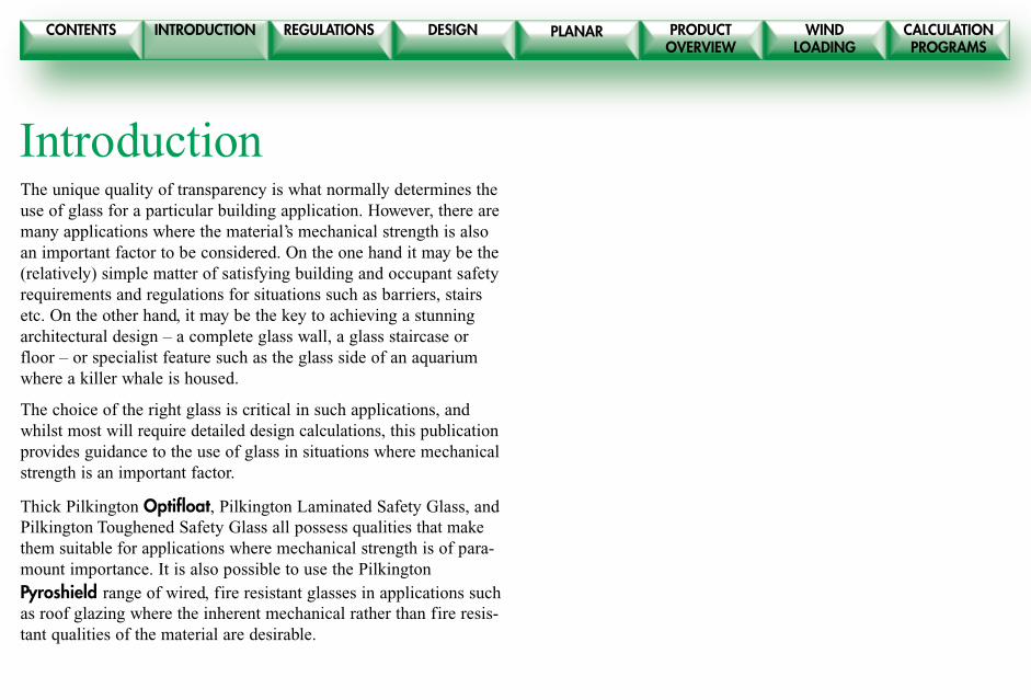
IntroductionThe unique quality of transparency is what normally determines theuse of glass for a particular building application. However, there aremany applications where the material’s mechanical strength is alsoan important factor to be considered. On the one hand it may be the(relatively) simple matter of satisfying building and occupant safetyrequirements and regulations for situations such as barriers, stairsetc. On the other hand, it may be the key to achieving a stunningarchitectural design – a complete glass wall, a glass staircase orfloor – or specialist feature such as the glass side of an aquariumwhere a killer whale is housed.
The choice of the right glass is critical in such applications, andwhilst most will require detailed design calculations, this publicationprovides guidance to the use of glass in situations where mechanicalstrength is an important factor.
Thick Pilkington Optifloat, Pilkington Laminated Safety Glass, andPilkington Toughened Safety Glass all possess qualities that makethem suitable for applications where mechanical strength is of para-mount importance. It is also possible to use the PilkingtonPyroshield range of wired, fire resistant glasses in applications suchas roof glazing where the inherent mechanical rather than fire resis-tant qualities of the material are desirable.
CONTENTS INTRODUCTION REGULATIONS DESIGN PRODUCTOVERVIEW
WINDLOADING
CALCULATIONPROGRAMS
PLANAR
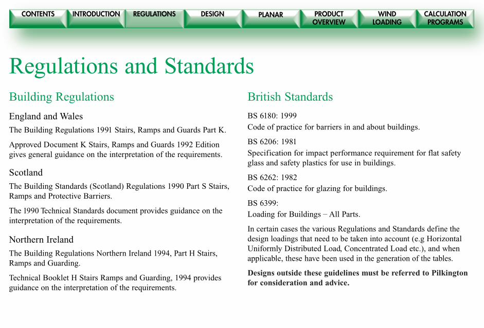
Regulations and StandardsBuilding Regulations
England and Wales
The Building Regulations 1991 Stairs, Ramps and Guards Part K.
Approved Document K Stairs, Ramps and Guards 1992 Editiongives general guidance on the interpretation of the requirements.
Scotland
The Building Standards (Scotland) Regulations 1990 Part S Stairs,Ramps and Protective Barriers.
The 1990 Technical Standards document provides guidance on theinterpretation of the requirements.
Northern Ireland
The Building Regulations Northern Ireland 1994, Part H Stairs,Ramps and Guarding.
Technical Booklet H Stairs Ramps and Guarding, 1994 providesguidance on the interpretation of the requirements.
British Standards
BS 6180: 1999
Code of practice for barriers in and about buildings.
BS 6206: 1981
Specification for impact performance requirement for flat safetyglass and safety plastics for use in buildings.
BS 6262: 1982Code of practice for glazing for buildings.
BS 6399:Loading for Buildings – All Parts.
In certain cases the various Regulations and Standards define thedesign loadings that need to be taken into account (e.g HorizontalUniformly Distributed Load, Concentrated Load etc.), and whenapplicable, these have been used in the generation of the tables.
Designs outside these guidelines must be referred to Pilkingtonfor consideration and advice.

CONTENTS INTRODUCTION REGULATIONS DESIGN PRODUCTOVERVIEW
WINDLOADING
CALCULATIONPROGRAMS
PLANAR
Design and ApplicationsThe following sections provide general guidance to therequired glass thickness, maximum areas, spans etc. forPilkington Glasses used in the following selection of popularapplications where mechanical strength is a major consideration:
● Free Standing Glass Protective Barriers
● Pilkington Toughened Safety Glass Infill Panels for Barriers
● Pilkington Laminated Safety Glass Infill Panels for Barriers
● Glass Mullions – full height
● Glass Floors
● Overhead Glazing
Houndshill Shopping Centre, Blackpool
CONTENTS INTRODUCTION REGULATIONS DESIGN PRODUCTOVERVIEW
WINDLOADING
CALCULATIONPROGRAMS
PLANAR
CONTENTS INTRODUCTION REGULATIONS DESIGN PRODUCTOVERVIEW
WINDLOADING
CALCULATIONPROGRAMS
PLANAR
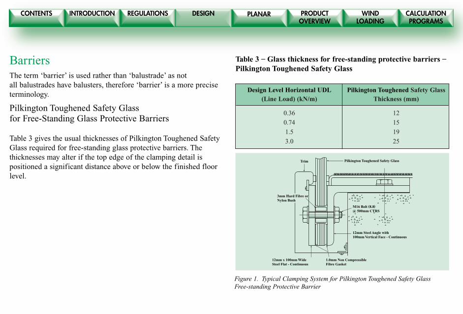
BarriersThe term ‘barrier’ is used rather than ‘balustrade’ as notall balustrades have balusters, therefore ‘barrier’ is a more preciseterminology.
Pilkington Toughened Safety Glassfor Free-Standing Glass Protective Barriers
Table 3 gives the usual thicknesses of Pilkington Toughened SafetyGlass required for free-standing glass protective barriers. Thethicknesses may alter if the top edge of the clamping detail ispositioned a significant distance above or below the finished floorlevel.
Table 3 – Glass thickness for free-standing protective barriers –Pilkington Toughened Safety Glass
Design Level Horizontal UDL Pilkington Toughened Safety Glass (Line Load) (kN/m) Thickness (mm)
0.36 12
0.74 15
1.5 19
3.0 25
Pilkington Toughened Safety Glass
3mm Hard Fibre orNylon Bush
M16 Bolt (8.8)@ 500mm CTRS
Trim
12mm Steel Angle with 100mm Vertical Face - Continuous
12mm x 100mm WideSteel Flat - Continuous
1.0mm Non CompressibleFibre Gasket
Figure 1. Typical Clamping System for Pilkington Toughened Safety GlassFree-standing Protective Barrier

CONTENTS INTRODUCTION REGULATIONS DESIGN PRODUCTOVERVIEW
WINDLOADING
CALCULATIONPROGRAMS
PLANAR
Pilkington Toughened Safety Glass Infill Panels forBarriers
Table 4 gives the maximum spans for Pilkington Toughened SafetyGlass infill panels attached at the ends by bolted connections to thebalusters. Although the spans given in the table are the technicaldesign limitations of the glass, in accordance with the principles ofBS6180, it is recommended that balustrade infill panels should belimited to a length of around 1500 to 2000mm, since the glass mayappear to be rather flexible to the casual observer if the spans arelonger than this.
Table 4 – Maximum spans for bolted PilkingtonToughened Safety Glass Infill panels for barriers(Applicable only for pane widths greater than 700mm)
Infill Loading Span Limit for Bolted From BS 6180 Pilkington Toughened Glass (mm)
UDL Point Load 6mm* 8mm* 10mm 12mm(kN/m2) (kN)
0.5 0.25 1400 1750 2100 2400
1.0 0.5 900 1450 1750 2050
1.5 1.5 N/A N/A 1200 1600
*6 and 8mm Pilkington Toughened Safety Glass will not be suitable if the freepath perpendicular to the barrier is larger than 1.5m, since it will not givecontainment (i.e. remain intact) at Class A of BS 6206: 1981.
��� ������ ��� �
���������������������������������������������������������������������������
yyyyyyyyyyyyyyyyyyyyyyyyyyyyyyyyyyyyyyyyyyyyyyyyyyyyyyyyyyyyyyyyyyyyyyyyyyy
���������������������������������������������������������������������������
yyyyyyyyyyyyyyyyyyyyyyyyyyyyyyyyyyyyyyyyyyyyyyyyyyyyyyyyyyyyyyyyyyyyyyyyyyy
50mm Dia.
20mm Dia. Holein Glass
6mm Thick Steel Spreader Plate
1mm Non CompressibleFibre Gasket
10mm Pilkington Toughened Safety Glass
3mm Hard Fibre or Nylon Bush
M10 Bolt
6mm x 50mm WideSteel Flat attached to structure
Span
Span
Width
Width
Figure 2. Typical bolt fixing arrangement for Pilkington ToughenedSafety Glass Infill Panel for a protective barrier
CONTENTS INTRODUCTION REGULATIONS DESIGN PRODUCTOVERVIEW
WINDLOADING
CALCULATIONPROGRAMS
PLANAR
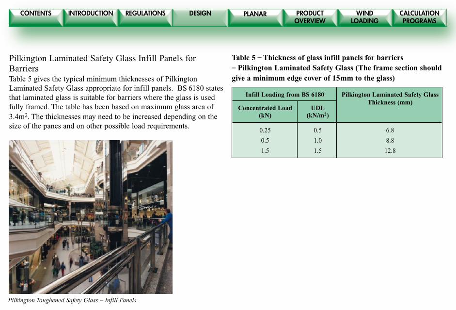
Pilkington Laminated Safety Glass Infill Panels forBarriersTable 5 gives the typical minimum thicknesses of PilkingtonLaminated Safety Glass appropriate for infill panels. BS 6180 statesthat laminated glass is suitable for barriers where the glass is usedfully framed. The table has been based on maximum glass area of3.4m2. The thicknesses may need to be increased depending on thesize of the panes and on other possible load requirements.
Table 5 – Thickness of glass infill panels for barriers– Pilkington Laminated Safety Glass (The frame section shouldgive a minimum edge cover of 15mm to the glass)
Infill Loading from BS 6180 Pilkington Laminated Safety GlassThickness (mm)
Concentrated Load UDL(kN) (kN/m2)
0.25 0.5 6.8
0.5 1.0 8.8
1.5 1.5 12.8
Pilkington Toughened Safety Glass – Infill Panels
CONTENTS INTRODUCTION REGULATIONS DESIGN PRODUCTOVERVIEW
WINDLOADING
CALCULATIONPROGRAMS
PLANAR
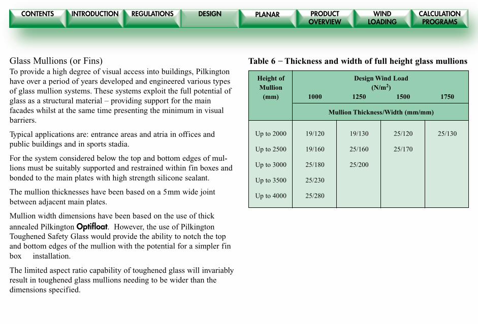
Glass Mullions (or Fins)To provide a high degree of visual access into buildings, Pilkingtonhave over a period of years developed and engineered various typesof glass mullion systems. These systems exploit the full potential ofglass as a structural material – providing support for the mainfacades whilst at the same time presenting the minimum in visualbarriers.
Typical applications are: entrance areas and atria in offices andpublic buildings and in sports stadia.
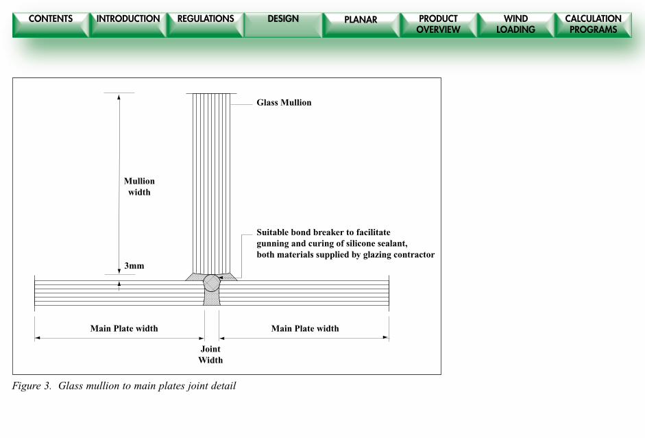
For the system considered below the top and bottom edges of mul-lions must be suitably supported and restrained within fin boxes andbonded to the main plates with high strength silicone sealant.
The mullion thicknesses have been based on a 5mm wide jointbetween adjacent main plates.
Mullion width dimensions have been based on the use of thickannealed Pilkington Optifloat. However, the use of PilkingtonToughened Safety Glass would provide the ability to notch the topand bottom edges of the mullion with the potential for a simpler finbox installation.
The limited aspect ratio capability of toughened glass will invariablyresult in toughened glass mullions needing to be wider than thedimensions specified.
Table 6 – Thickness and width of full height glass mullions
Height of Design Wind LoadMullion (N/m2)
(mm) 1000 1250 1500 1750
Mullion Thickness/Width (mm/mm)
Up to 2000 19/120 19/130 25/120 25/130
Up to 2500 19/160 25/160 25/170
Up to 3000 25/180 25/200
Up to 3500 25/230
Up to 4000 25/280
CONTENTS INTRODUCTION REGULATIONS DESIGN PRODUCTOVERVIEW
WINDLOADING
CALCULATIONPROGRAMS
PLANAR
����������������������������������������������������������������������������������������������������������������������������������������������������������������������������������������������������������������������������������������������������������������������������������������������������������������������������������������������������������������������������������������������������������������
yyyyyyyyyyyyyyyyyyyyyyyyyyyyyyyyyyyyyyyyyyyyyyyyyyyyyyyyyyyyyyyyyyyyyyyyyyyyyyyyyyyyyyyyyyyyyyyyyyyyyyyyyyyyyyyyyyyyyyyyyyyyyyyyyyyyyyyyyyyyyyyyyyyyyyyyyyyyyyyyyyyyyyyyyyyyyyyyyyyyyyyyyyyyyyyyyyyyyyyyyyyyyyyyyyyyyyyyyyyyyyyyyyyyyyyyyyyyyyyyyyyyyyyyyyyyyyyyyyyyyyyyyyyyyyyyyyyyyyyyyyyyyyyyyyyyyyyyyyyyyyyyyyyyyyyyyyyyyyyyyyyyyyyyyyyyyyyyyyyyyyyyyyyyyyyyyyyyyyyyyyyyyyyyyyyyyyyyyyyyyyyyyyyyyyyyyyyyyyyy
�����������������������������������������������������������������������������������������������������������������������������������������������������������������������������������������������������������������������������������������������������������������������������������������������������������������������������������������������������������������������������������������������������������������������������������������������������������������������������������������������������������������������������������������������������������������������������������������������������������������������������
yyyyyyyyyyyyyyyyyyyyyyyyyyyyyyyyyyyyyyyyyyyyyyyyyyyyyyyyyyyyyyyyyyyyyyyyyyyyyyyyyyyyyyyyyyyyyyyyyyyyyyyyyyyyyyyyyyyyyyyyyyyyyyyyyyyyyyyyyyyyyyyyyyyyyyyyyyyyyyyyyyyyyyyyyyyyyyyyyyyyyyyyyyyyyyyyyyyyyyyyyyyyyyyyyyyyyyyyyyyyyyyyyyyyyyyyyyyyyyyyyyyyyyyyyyyyyyyyyyyyyyyyyyyyyyyyyyyyyyyyyyyyyyyyyyyyyyyyyyyyyyyyyyyyyyyyyyyyyyyyyyyyyyyyyyyyyyyyyyyyyyyyyyyyyyyyyyyyyyyyyyyyyyyyyyyyyyyyyyyyyyyyyyyyyyyyyyyyyyyyyyyyyyyyyyyyyyyyyyyyyyyyyyyyyyyyyyyyyyyyyyyyyyyyyyyyyyyyyyyyyyyyyyyyyyyyyyyyyyyyyyyyyyyyyyyyyyyyyyyyyyyyyyyyyyyyyyyyyyyyyyyyyyyyyyyyyyyyyyyyyyyyyyyyyyyyyyyyyyyyyyyyyyyyyyyyyyyyyyyyyyyyyyyyyyyyyyyyyyyyyyyyy
���
���
���
yyy
yyy
yyy
JointWidth
3mm
Suitable bond breaker to facilitategunning and curing of silicone sealant,both materials supplied by glazing contractor
Glass Mullion
Mullionwidth
Main Plate width Main Plate width
Figure 3. Glass mullion to main plates joint detail
CONTENTS INTRODUCTION REGULATIONS DESIGN PRODUCTOVERVIEW
WINDLOADING
CALCULATIONPROGRAMS
PLANAR
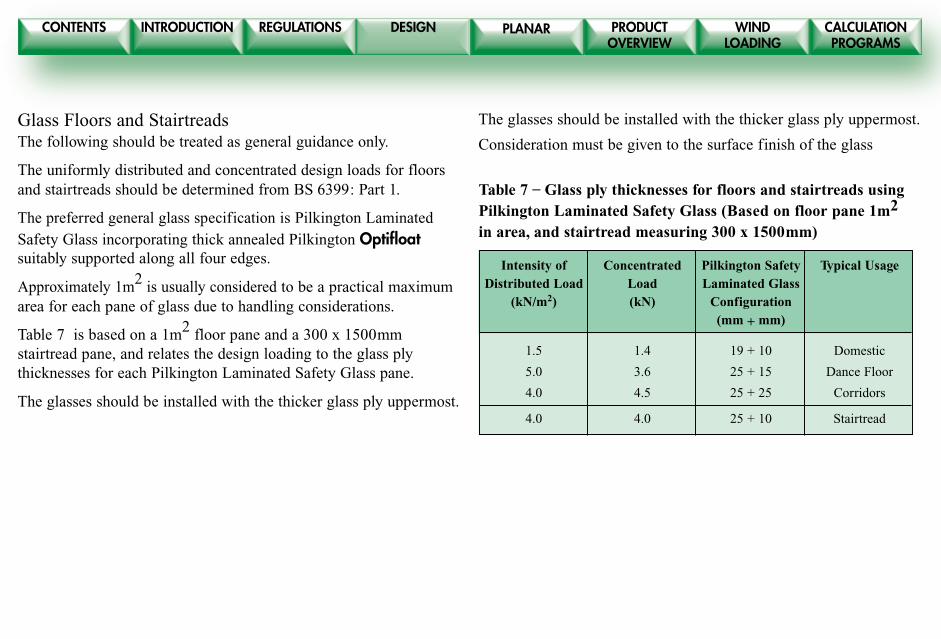
Glass Floors and StairtreadsThe following should be treated as general guidance only.
The uniformly distributed and concentrated design loads for floorsand stairtreads should be determined from BS 6399: Part 1.
The preferred general glass specification is Pilkington LaminatedSafety Glass incorporating thick annealed Pilkington Optifloatsuitably supported along all four edges.
Approximately 1m2 is usually considered to be a practical maximumarea for each pane of glass due to handling considerations.
Table 7 is based on a 1m2 floor pane and a 300 x 1500mmstairtread pane, and relates the design loading to the glass plythicknesses for each Pilkington Laminated Safety Glass pane.
The glasses should be installed with the thicker glass ply uppermost.
The glasses should be installed with the thicker glass ply uppermost.
Consideration must be given to the surface finish of the glass
Table 7 – Glass ply thicknesses for floors and stairtreads usingPilkington Laminated Safety Glass (Based on floor pane 1m2
in area, and stairtread measuring 300 x 1500mm)
Intensity of Concentrated Pilkington Safety Typical UsageDistributed Load Load Laminated Glass
(kN/m2) (kN) Configuration(mm + mm)
1.5 1.4 19 + 10 Domestic
5.0 3.6 25 + 15 Dance Floor
4.0 4.5 25 + 25 Corridors
4.0 4.0 25 + 10 Stairtread
CONTENTS INTRODUCTION REGULATIONS DESIGN PRODUCTOVERVIEW
WINDLOADING
CALCULATIONPROGRAMS
PLANAR
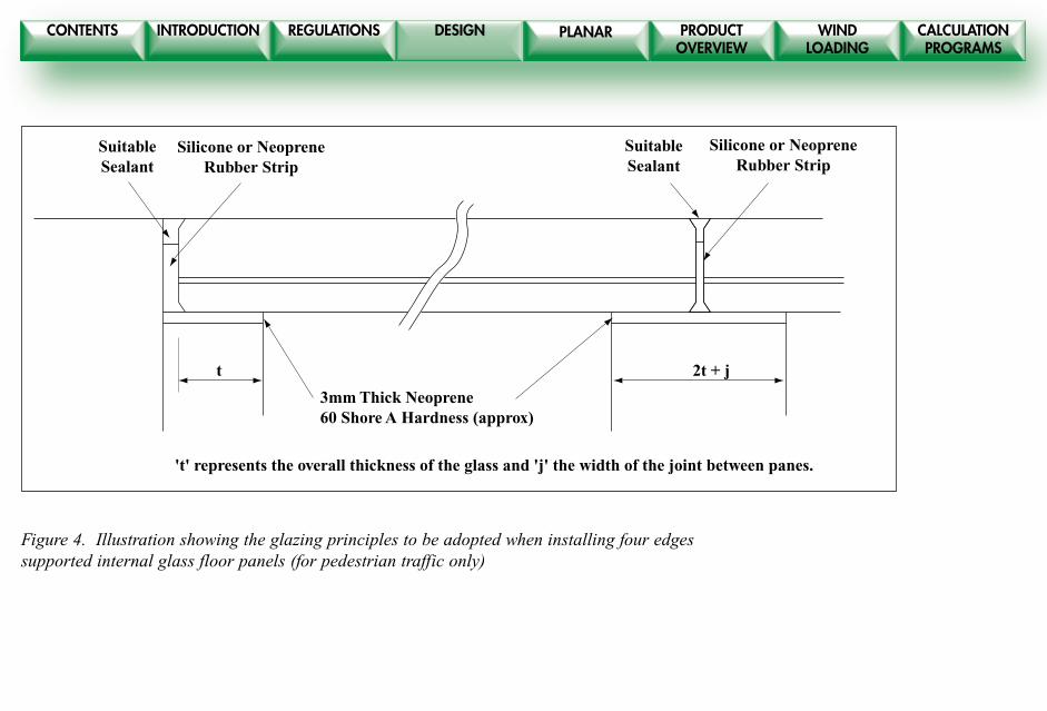
t 2t + j
Silicone or NeopreneRubber Strip
3mm Thick Neoprene60 Shore A Hardness (approx)
SuitableSealant
Silicone or NeopreneRubber Strip
SuitableSealant
't' represents the overall thickness of the glass and 'j' the width of the joint between panes.
Figure 4. Illustration showing the glazing principles to be adopted when installing four edgessupported internal glass floor panels (for pedestrian traffic only)
CONTENTS INTRODUCTION REGULATIONS DESIGN PRODUCTOVERVIEW
WINDLOADING
CALCULATIONPROGRAMS
PLANAR
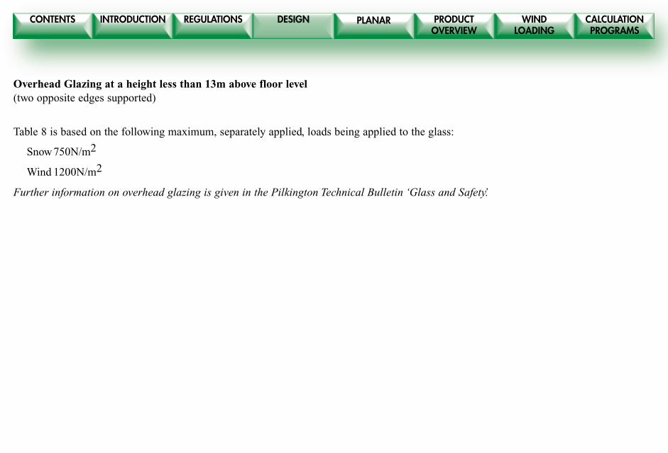
Overhead Glazing at a height less than 13m above floor level(two opposite edges supported)
Table 8 is based on the following maximum, separately applied, loads being applied to the glass:
Snow750N/m2
Wind 1200N/m2
Further information on overhead glazing is given in the Pilkington Technical Bulletin ‘Glass and Safety.’
CONTENTS INTRODUCTION REGULATIONS DESIGN PRODUCTOVERVIEW
WINDLOADING
CALCULATIONPROGRAMS
PLANAR
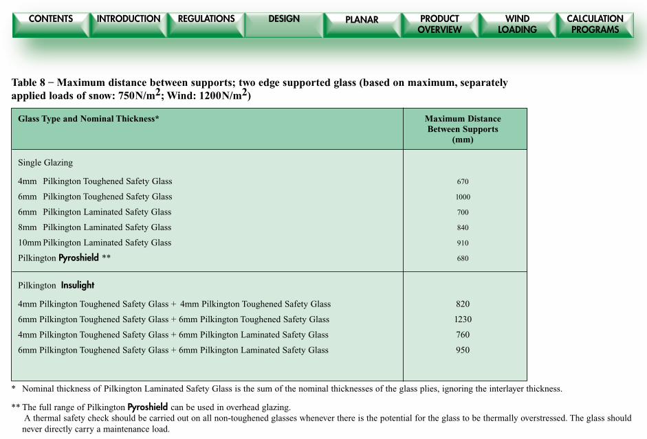
Table 8 – Maximum distance between supports; two edge supported glass (based on maximum, separatelyapplied loads of snow: 750N/m2; Wind: 1200N/m2)
Glass Type and Nominal Thickness* Maximum DistanceBetween Supports
(mm)
Single Glazing
4mm Pilkington Toughened Safety Glass 670
6mm Pilkington Toughened Safety Glass 1000
6mm Pilkington Laminated Safety Glass 700
8mm Pilkington Laminated Safety Glass 840
10mm Pilkington Laminated Safety Glass 910
Pilkington Pyroshield ** 680
Pilkington Insulight
4mm Pilkington Toughened Safety Glass + 4mm Pilkington Toughened Safety Glass 820
6mm Pilkington Toughened Safety Glass + 6mm Pilkington Toughened Safety Glass 1230
4mm Pilkington Toughened Safety Glass + 6mm Pilkington Laminated Safety Glass 760
6mm Pilkington Toughened Safety Glass + 6mm Pilkington Laminated Safety Glass 950
* Nominal thickness of Pilkington Laminated Safety Glass is the sum of the nominal thicknesses of the glass plies, ignoring the interlayer thickness.
** The full range of Pilkington Pyroshield can be used in overhead glazing. A thermal safety check should be carried out on all non-toughened glasses whenever there is the potential for the glass to be thermally overstressed. The glass shouldnever directly carry a maintenance load.
CONTENTS INTRODUCTION REGULATIONS DESIGN PRODUCTOVERVIEW
WINDLOADING
CALCULATIONPROGRAMS
PLANAR
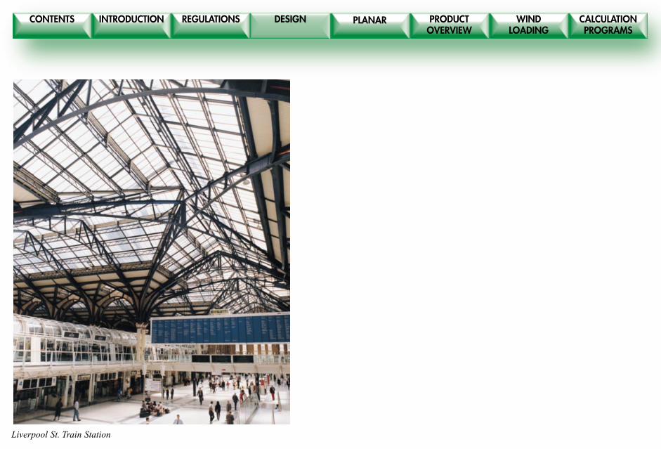
Liverpool St. Train Station

CONTENTS INTRODUCTION REGULATIONS DESIGN PRODUCTOVERVIEW
WINDLOADING
CALCULATIONPROGRAMS
PLANAR
This publication gives a general description of the product andmaterials. It is the responsibility of the user of this document to ensure
that their use is appropriate for any particular application and that suchapplication complies with all relevant local and and national legislation,
standards, codes of practice and other requirements.
Pilkington United Kingdom Limited hereby disclaim all liabilityhowsoever arising from any error in or omission from this publication
and all consequences of relying on it.
Pilkington product names shown in Futura Heavy are trademarks of thePilkington Group.
Pilkington Building ProductsPrescot Road St Helens England WA10 3TTTelephone 01744 692000 Fax 01744 613049