giza surgical technique -...
TRANSCRIPT

GIZA® Surgical Technique
• Vertebral Body Replacement System
Manufactured by

GIZA Surgical Technique
2
Titanium alloy material provides mechanical integrity during insertion and distraction, x-ray visibility, and biocompatibility*
One step locking of the distraction mechanism Fenestration to promote
vascularization during the fusion process
Rotatable superior endplate with variable lordotic angles
Fixed Inferior Endplate
Optional in-situ insertion of bone graft
*Data on file
Holder/Distractorconnection

3
GIZA Surgical Technique
Table of Contents
Exposure . . . . . . . . . . . . . . . . . . . . . . . . . . . . . . . . . . . . . . . . . . . . . . . . . . . . . . . . . . . . . 4
Implant Measurement . . . . . . . . . . . . . . . . . . . . . . . . . . . . . . . . . . . . . . . . . . . . . . . . . . 5
Implant Selection . . . . . . . . . . . . . . . . . . . . . . . . . . . . . . . . . . . . . . . . . . . . . . . . . . . . . . 5
Endplate Assembly . . . . . . . . . . . . . . . . . . . . . . . . . . . . . . . . . . . . . . . . . . . . . . . . . . . . . 6
Endplate Adjustment . . . . . . . . . . . . . . . . . . . . . . . . . . . . . . . . . . . . . . . . . . . . . . . . . . . 6
Bone Graft Placement Pre-Implantation (Optional) . . . . . . . . . . . . . . . . . . . . . . . . . 7
GIZA Implant Attachment . . . . . . . . . . . . . . . . . . . . . . . . . . . . . . . . . . . . . . . . . . . . . . 8
GIZA Implant Insertion . . . . . . . . . . . . . . . . . . . . . . . . . . . . . . . . . . . . . . . . . . . . . . . . 9
Implant Removal . . . . . . . . . . . . . . . . . . . . . . . . . . . . . . . . . . . . . . . . . . . . . . . . . . . . . . 10
Bone Graft Placement Post-Implantation (Optional) . . . . . . . . . . . . . . . . . . . . . . . 10
Supplemental Fixation . . . . . . . . . . . . . . . . . . . . . . . . . . . . . . . . . . . . . . . . . . . . . . . . . 10
Instruments . . . . . . . . . . . . . . . . . . . . . . . . . . . . . . . . . . . . . . . . . . . . . . . . . . . . . . . . . 11
Implants . . . . . . . . . . . . . . . . . . . . . . . . . . . . . . . . . . . . . . . . . . . . . . . . . . . . . . . . . . . . 11
Conditions for Use . . . . . . . . . . . . . . . . . . . . . . . . . . . . . . . . . . . . . . . . . . . . . . . . . . . . 12
IntroductionThe following technique describes an open thoracolumbar corpectomy procedure . This technique may be used in anterior or anterolateral approaches in the thoracolumbar spine (T1-L5) based on the pathology being addressed and surgeon preference .
The GIZA Vertebral Body Replacement System is indicated for use in the cervical and thoracolumbar spine in OUS (Outside United States) markets .
Description
The GIZA Vertebral Body Replacement System consists of a titanium alloy (TA6V ELI) Distractible In Situ implant, which enables the surgeon to customize the height of the implant after implantation . Adjustments of the implant height are achieved in situ as a result of the locking mechanism which maintains distraction .
A 14mm diameter footprint is available in three height ranges, including 18 - 22mm, 23 - 32mm and 33 - 54mm . Each implant comes fully assembled with the option of a rotatable superior endplate in 2, 5, 7, 8 and 10 degrees of lordosis .

GIZA Surgical Technique
4
ExposureANTERIOR APPROACH
Patient Positioning
Patient positioning on the operating table is dependent on the level(s) to be operated . For the anterior approach, the patient is typically placed in the supine position with or without a small intrascapular bump to gently extend the neck . Wrist straps may be applied to help facilitate gentle caudal distraction of the shoulders to help improve radiographic visualization of the spine, see Figure 1 .
Surgical Approach
Through an anterior approach, the anterior aspect of the spinal column is exposed . Intraoperative x-ray or fluoroscopy is used to help confirm the operative level . A partial or full corpectomy or vertebrectomy is performed . The bony endplates are prepared for implant insertion using standard surgical procedures and instrumentation, see Figures 2a and 2b .
Figure 1: Example of patient placed in the supine position
Figure 2a: Example of a corpectomy of a thoracic vertebral body
Figure 2b: Example of a vertebrectomy of a thoracic vertebra
ANTEROLATERAL APPROACH
Patient Positioning
Patient positioning on the operating table is dependent on the level(s) to be operated . For the anterolateral approach, the patient is typically placed in the lateral decubitus position, see Figure 3 . Patient will be placed on either the left side or right side depending on level being operated .
Surgical Approach
Through an anterolateral incision the thoracolumbar spine is exposed . Intraoperative x-ray or fluoroscopy is used to help confirm the operative level . A partial or full corpectomy or vertebrectomy is performed . The bony endplates are prepared for implant insertion using standard surgical procedures and instrumentation, see Figures 2a and 2b .
Figure 3: Example of patient placed in the lateral decubitus position

5
GIZA Surgical Technique
The appropriate size implant can be determined preoperatively, by measuring the defect from the patient’s films or CT scans . However, the measurement should be confirmed in situ with an Intervertebral Caliper or ruler . It is recommended to measure in situ from the posterior aspect of the inferior endplate of the vertebral body above the affected level to the posterior aspect of the superior endplate of the vertebral body below the affected level, see Figure 4 .
Note: Implant height should be confirmed via fluoroscopy.
Figure 4: Example of determining implant sizing using the Intervertebral Caliper in conjunction with the Implant Sizing Gauge
Implant Selection The GIZA Vertebral Body Replacement System consists of a titanium alloy (TA6V ELI) Distractible In Situ implant, which enables the surgeon to customize the height of the implant after implantation . Adjustments of the implant height are achieved in situ as a result of the locking mechanism which maintains distraction .
A 14mm diameter footprint is available in three height ranges, including 18 - 22mm, 23- 32mm and 33 - 54mm . Each implant comes fully assembled with the option of a rotatable superior endplate . Please refer to the chart for all possible combinations .
Ø14mm Implant Distraction Range Lordotic Angle Options
18 – 22mm2°, 5°
5°, 8°
23 – 32mm2°, 5°
7°, 10°
33 – 54mm2°, 5°
7°, 10°
Implant Measurement
Intervertebral Caliper
Implant Sizing Gauge

GIZA Surgical Technique
6
The GIZA VBR Implant comes fully assembled and sterile packaged . The 14mm diameter implants have the option of a rotatable superior endplate for those cases in which lordosis is desired to provide sagittal alignment and increased stabilization of the implant construct, see Figure 5 . The inferior endplate is fixed in a neutral position and does not allow for rotation .
Note: The implant comes preassembled and the endplates are not meant to be removable. If rotated more than 180 degrees, there is potential for the endplates to detach from the implant.
Figure 5: Example of varying degrees of implant lordosis achievable by rotating the superior endplate of the implant
Adjustment of the superior endplate is done pre-operatively by using the Endplate Holder . The surgeon can increase or decrease the angulation by rotating the superior endplate with the Endplate Holder . To obtain the highest degree of lordosis, rotate the endplate 180 degrees .
Step 1: Use the Endplate Holder to disengage the locking nut to allow for rotation of the superior endplate, see Figure 6a .
Step 2: Turn the Endplate Holder to adjust lordosis . Turning 180 degrees will reach maximum lordotic angle for each height, see Figure 6b .
Figure 6b
Figure 6a
Endplate Assembly
Endplate Adjustment
7
GIZA Surgical Technique
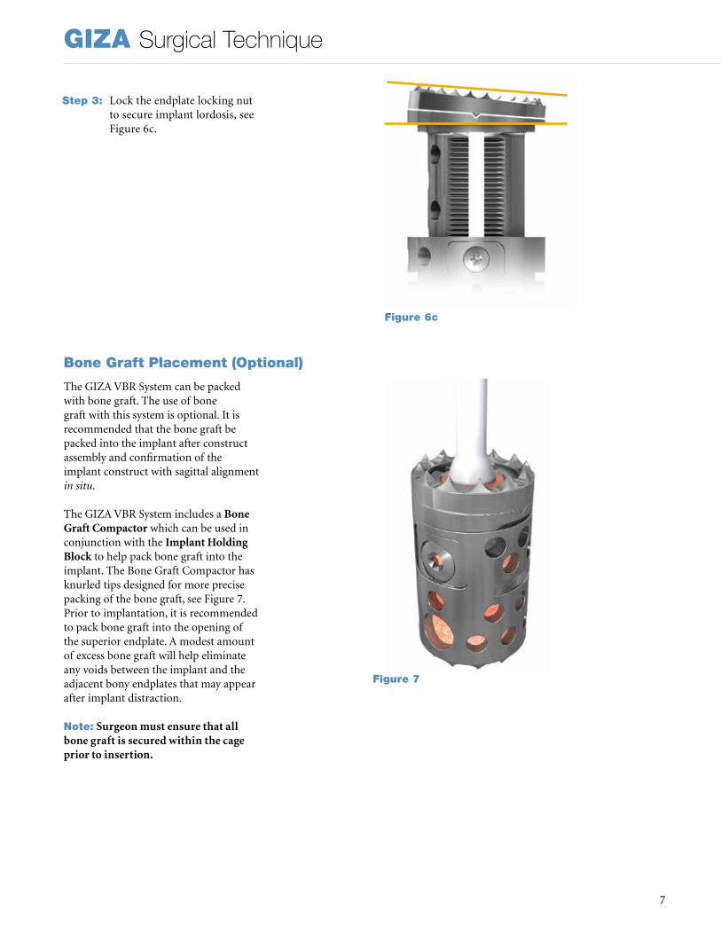
Step 3: Lock the endplate locking nut to secure implant lordosis, see Figure 6c .
Figure 6c
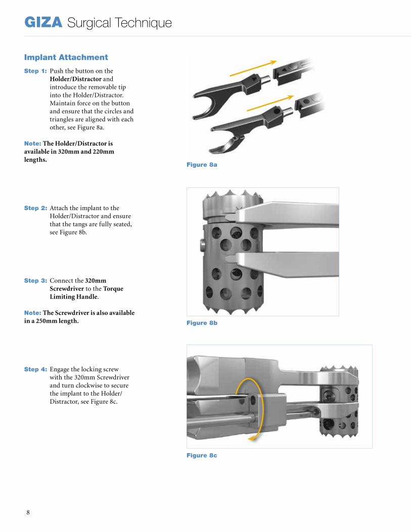
The GIZA VBR System can be packed with bone graft . The use of bone graft with this system is optional . It is recommended that the bone graft be packed into the implant after construct assembly and confirmation of the implant construct with sagittal alignment in situ .
The GIZA VBR System includes a Bone Graft Compactor which can be used in conjunction with the Implant Holding Block to help pack bone graft into the implant . The Bone Graft Compactor has knurled tips designed for more precise packing of the bone graft, see Figure 7 . Prior to implantation, it is recommended to pack bone graft into the opening of the superior endplate . A modest amount of excess bone graft will help eliminate any voids between the implant and the adjacent bony endplates that may appear after implant distraction .
Note: Surgeon must ensure that all bone graft is secured within the cage prior to insertion.
Bone Graft Placement (Optional)
Figure 7
GIZA Surgical Technique
8
Step 1: Push the button on the
Holder/Distractor and introduce the removable tip into the Holder/Distractor . Maintain force on the button and ensure that the circles and triangles are aligned with each other, see Figure 8a .
Note: The Holder/Distractor is available in 320mm and 220mm lengths.
Step 2: Attach the implant to the Holder/Distractor and ensure that the tangs are fully seated, see Figure 8b .
Step 3: Connect the 320mm Screwdriver to the Torque Limiting Handle .
Note: The Screwdriver is also available in a 250mm length.
Step 4: Engage the locking screw with the 320mm Screwdriver and turn clockwise to secure the implant to the Holder/Distractor, see Figure 8c .
Figure 8a
Figure 8b
Figure 8c
Implant Attachment

9
GIZA Surgical Technique
Implant InsertionStep 1: Insert the implant into the
disc space taking care to protect the integrity of the surgical site . The Holder/Distractor ratchets in 1mm increments . Carefully monitor for overdistraction, especially in cases of spondylectomy and trauma . Once desired height is achieved, temporarily lock the proximal end of the Holder/Distractor to maintain distraction, see Figure 9a .
Step 2: Next, secure desired distraction level by engaging the locking screw and turn the 320mm Screwdriver clockwise until fully tightened to 1 .1 Nm, see Figure 9b .
Note: The locking screw should be firmly hand tightened.
Note: If adjustment is needed, the implant locking mechanism must be unscrewed 3.5 to 4 rotations from the tightened position, to free the superior cylinder from the inferior one. No more than 4 counterclockwise rotations should be applied to the locking screw, as doing so could potentially lead to disassembly of the implant’s locking mechanism.
Step 3: To disengage the implant from the Holder/Distractor, engage the screw and turn the 320mm Screwdriver counterclockwise until the Holder/Distractor can be released from the implant, see Figure 9c . Gently remove the Holder/Distractor from the disc space .
Note: Fluoroscopy may be useful in determining the appropriate final positioning.
Figure 9a
Figure 9b
Figure 9c

GIZA Surgical Technique
10
Implant RemovalIf fusion or bone graft growth occurs, the device will be deeply integrated into the bony tissues . As a result, the GIZA system is not intended for removal unless the management of a complication or adverse event requires removal . Standard instruments may be used to hold and disengage the device from the vertebrae . Any decision by a physician to remove the device must take into consideration such factors as the risk to the patient of the additional surgical procedure as well as the difficulty of removal . The following steps can be used if the GIZA device must be removed:
Step 1: Insert the Holder/Distractor and engage the locking screw . Turn the 320mm Screwdriver clockwise to tighten the implant to the inserter, see Figure 10a .
Step 2: Slightly distract the implant to allow the locking mechanism to be unscrewed .
Step 3: Rotate the locking screw counterclockwise to reduce the height of the implant until it is possible to remove the implant from the defect, see Figure 10b .
Note: No more than 4 counterclockwise rotations should be applied to the locking screw, as doing so could potentially lead to disassembly of the implant’s locking mechanism.
Bone Graft Placement In SituAutogenous bone grafting material may be placed lateral, ventral, and/or dorsal to the implanted GIZA VBR Implant .
Supplemental FixationIf supplemental fixation was not applied prior to the insertion of the GIZA implant, it must be applied once the implant is in place . The supplemental internal fixation systems that may be used with GIZA include, but are not limited to, Stryker Spine plate or rod systems (Xia Spinal System, Radius Spinal System, Trio+ Spinal System, Mantis Spinal System, or Thor Plating System) .
Figure 10a
Figure 10b
GIZA pictured with the Xia 3 Spinal System
GIZA pictured with the Xia Anterior Spinal System

11
GIZA Surgical Technique
Instruments
Reference Number Description
Quantity/Set
48293320 Holder/Distractor Lg 320mm 1
48293220 Holder/Distractor Lg 220mm 1
48293014 Distractor Tips for 14mm Implant 1
48293114 Endplate Holder for 14mm Implant 1
48293132 Screwdriver Lg 320mm 1
48293125 Screwdriver Lg 250mm 1
48293402 Torque Limiting Handle 1
48293403 Bone Graft Compactor 1
48293404 Implant Holding Block 1
48293405 Intervertebral Caliper 1
48293406 Implant Sizing Gauge 1
48293400 Instruments Tray with Silcone Inserts 1
48293401 Instruments Tray Lid 1
Implants
Reference Number Diameter
DistractionRange
LordoticAngle
Quantity/Set
48291482S Ø14mm 18-22mm 2, 5 Degrees 2
48291485S Ø14mm 18-22mm 5, 8 Degrees 1
48291422S Ø14mm 23-32mm 2, 5 Degrees 2
48291427S Ø14mm 23-32mm 7, 10 Degrees 1
48291432S Ø14mm 33-54mm 2, 5 Degrees 2
48291437S Ø14mm 33-54mm 7, 10 Degrees 1
GIZA Surgical Technique
12
DESCRIPTION OF THE DEVICEThe corpectomy implant is in the form of an assembly of two cylindrical elements, one sliding over the other . An integrated locking system allows locking the implant once the distraction is finished . The vertebral plates positioned at each end adjust the angulation of the device to the intervertebral angulation . The upper plate and the lower plate have a notched surface to help anchor it with the vertebrae involved .
The device, which is expandable in situ, permits the vertebral segment involved to be distracted during the surgery . The implant can be distracted by a specific instrument that simultaneously grips and distracts it .
DEVICE MATERIALSThe corpectomy implant is made up of titanium alloy TA6V ELI parts that can be implanted according to standards ISO 5832-3 or ASTM-F 136 . This material is not compatible with stainless steel or other metals .
INDICATIONS FOR USE (USA)The GIZA Vertebral Body Replacement is intended for use during open surgical procedures in the thoracolumbar spine (T1-L5) to replace a collapsed, damaged, or unstable vertebral body due to tumor or trauma (e .g . fracture) . The GIZA Vertebral Body Replacement System is intended to be used with supplemental internal spinal fixation systems that have been labeled for use in the thoracic and lumbar spine (i .e . posterior pedicle screw and rod systems, anterior plate systems, and anterior screw and rod systems) The use of allograft or autograft with the GIZA Vertebral Body Replacement device is optional .
INDICATIONS FOR USE (OUTSIDE THE USA)The corpectomy implant is a surgical implant that allows reconstructing of the intervertebral space in the cervical and thoracolumbar spine . This device is mainly intended to be used in tumoral and traumatic spinal surgery . The indications include:• Vertebral body tumor• Anterior column fracture• Cervical stenosis requiring single or
multisegment reconstruction
CONTRAINDICATIONSThe corpectomy implant should not be used in patients in the following conditions: • Local infection or inflammation• Vertebral osteoporosis• Pregnancy• Allergy or intolerance to titanium or its
alloys• Incompatible age and physical condition
of the patient• Any case not included in the indications
The corpectomy implant is not designed, intended or sold for uses other than those indicated .
WARNINGS• Never reuse a GIZA implant .• Only surgeons familiar with the GIZA
surgical technique should perform this surgery .
• Instruments are supplied non-sterile and must be sterilized prior to use .
POSSIBLE SIDE EFFECTSThe following potential side effects (separate or in combination), although not observed, could occur and result from the implantation of the corpectomy implantation:• Infection,• Intolerance to the material,• Disassembly, deformation and/or
breakage of elements,• Damage of the dura mater and/or nerve
roots .
Note: An additional surgical procedure may be necessary to correct a side effect .
Warning: A completely satisfactory result is not systematically obtained with each surgical procedure . This is particularly true in spinal surgery, where numerous external elements can compromise the results .
SURGICAL PRECAUTIONSThe surgeon should be completely familiar with the device, the method of application, the instruments, and the surgical technique . The corpectomy implant should be implanted according to the recommended surgical technique . The corpectomy implant should be chosen as a function of the height to be restored and the inclination of the vertebral plates should be adjusted to conform to the vertebral segment; an unsuitable height may compromise the clinical result . Before implanting the device, the vertebral endplates should be carefully curetted and
debrided without being weakened in order to prevent subsidence of the corpectomy implant . The entire surface of the implant plates should be in contact with the adjacent vertebral body endplates . However, it is important to keep the vertebral body endplates intact . The proper positioning of the implant with regard to the vertebrae can be confirmed by x-ray . The locking screw should be firmly hand tightened . After implantation, the lot number and the reference of the GIZA corpectomy implant should systematically be recorded in the patient’s surgical record .
PRECAUTIONSThe corpectomy implant should be implanted only by experienced spinal surgeons who specialize in the spinal column, and who have been specifically trained in the use of this device and instrumentation .
Knowledge of the preoperative and intraoperative procedures, the surgical technique, the choice of implant size and its placement are essential for surgeons to optimally use the device . All these considerations will considerably affect the clinical results for the patient .
Patients should be advised of the pre-, intra- and postoperative procedures .
Be in an aseptic environment when opening the device packaging .
Handle the device with care so it does not contact other objects that could damage it . Damaged implants will not function reliably .
The device should not be used with components from other manufacturers .Based on the fatigue testing results, the physician/surgeon should consider the levels of implantation, patient weight, patient activity level, and other patient conditions which may impact on the performance of the system .
The GIZA device has not been evaluated for safety and compatibility in the MR environment . The GIZA device has not been tested for heating or migration in the MR environment
CAUTION (USA only)Sale of the GIZA VBR is restricted to use by or on the order of a physician .

13
GIZA Surgical Technique
NOTES:

GIZA Surgical Technique
14
NOTES:

15
GIZA Surgical Technique
NOTES:

A surgeon must always rely on his or her own professional clinical judgment when deciding whether to use a particular product when treating a particular patient . Stryker does not dispense medical advice and recommends that surgeons be trained in the use of any particular product before using it in surgery .
The information presented is intended to demonstrate the breadth of Stryker product offerings . A surgeon must always refer to the package insert, product label and/or instructions for use before using any Stryker product . Products may not be available in all markets because product availability is subject to the regulatory and/or medical practices in individual markets . Please contact your Stryker representative if you have questions about the availability of Stryker products in your area . Stryker Corporation or its divisions or other corporate affiliated entities own, use or have applied for the following trademarks or service marks: GIZA, Mantis, Radius, Stryker, Thor, Trio, Xia . . All other trademarks are trademarks of their respective owners or holders .
Literature Number: TLGIZ-ST-1_13842SC/GS 04/17
Copyright © 2017 StrykerPrinted in USA
Manufactured By:Eden Spine LLC 377 Maitland Ave - Suite 1015Altamonte Springs, FL 32701Phone: +1 407 900 9986Fax: +1 407 264 8303
Eden Spine Europe 41, rue du 31 Décembre1207 Genève – SwitzerlandPhone: +41 22 310 29 11
Distributed by:OUS Distribution:Stryker Spine SALe Cret-du-Locle 10a2300 La Chaux-de-FondsSwitzerlandPhone: +41 32 924 6000
US Distribution:Stryker Spine2 Pearl CourtAllendale, NJ 07401-1077, USAPhone: +1 201 760 8000