giving energy more value - momentum automationmomentum-automation.com/tekstovi i...
TRANSCRIPT


Più valore all’energia - Giving energy more value
Sinus PentaSINUS PENTA BOX
SINUS PENTA CABINET
SINUS PENTA 2T/4T
SINUS PENTA 5T/6T
Dimensioni e pesi - Dimensions and weight
SINUS PENTA IP54
Accessori - Accessories
Sinus NSinus MSinus K Software Lift
ASAC0/ASAC1
ASAB
ASAMV
DCREG2-DCREG4
CU400
MJ-MA
Remote drive
ApplicazioniApplicationsHVAC
WATER
CEMENT
MINING
REGENERATIVE
LIFT
CRANES
MV STEP DOWN - STEP UP
Accessori - Accessories
Worldwide
IndiceTable of contents
2
48
10
14
22
30
31
32
343842
46
50
56
60
66
68
72
74
76
78
80
81
82
84
85
86
88
94

2
Più valore all’energiaGiving energy more value

3
Elettronica Santerno nasce quaranta anni fa in provincia di Bologna come realtà unica nel suo genere. Un’azienda composta da una squadra di professionisti che collaborano in team, tutti altamente specializzati nello studio e sviluppo di soluzioni innovative nell’elet-tronica di potenza applicata. Oggi Santerno, società del Gruppo Carraro, ha una dimensione internazionale, con sedi in ogni area geografi ca strategica come Brasile, Spagna, Cina, India, Germania, Stati Uniti, Russia e Italia.Negli ultimi anni la nostra società ha registrato importanti tassi di crescita, e tale percorso sta proseguendo in modo importante con multipli che defi niscono le dimensioni di un solido successo. A dirlo sono i nostri clienti che ci danno ragione giorno dopo giorno garan-tendo questi risultati. Il mercato mondiale ha riconosciuto e premiato la forte capacità innovativa di Santerno che oltre ad essere leader in Italia negli inverter per applicazioni fotovoltaiche ha trovato riscontri molto positivi in Spagna, Cina e soprattutto in Germania, primo mercato mondiale per tale settore. Santerno sta vivendo un momento decisamente positivo, in controtendenza rispetto ai macro-trend dell’economia, e prevediamo un ulteriore sviluppo nel medio e lungo periodo. Questo è possibile grazie alle consolidate competenze del nostro staff, nonché al profondo know-how tecnologico consolidato nei nostri prodotti, la cui gamma è oggi in grado di soddisfare le più svariate esigenze e richieste applicative sia nell’ambito domestico che in quello industriale. Abbiamo una missione precisa: vogliamo offrire un prodotto altamente performante, ricco di tecnologia, sicuro ed affi dabile, ma che nel contempo parli la lingua dell’utente, con un interfaccia semplice, per un’ottimale gestione.
È questo il nostro modo di guardare al futuro. È così che vogliamo dare più valore all’energia, come recita il nostro motto.
Marco TecchioAmministratore Delegato - Santerno
Elettronica Santerno was established near Bologna, Italy, in the 1970. It has always been a unique company, boasting a team of specia-lists cooperating together for the development of innovative solutions in the fi eld of applied power electronics. Santerno is now part of the Carraro Group and has conquered the international market. It has premises in the most strategic areas worldwide, such as Brazil, Spain, China, India, Germany, United States, Russia and Italy.Santerno has remarkably grown in the past few years and its turnover is increasing by multiples, thus evidencing its well-established success. This is true thanks to our Customers, who trust in Santerno and allow us to consolidate our outstanding position day by day.The global market has acknowledged Santerno’s peculiarity, namely its capability of exploiting and promoting new and innovative technologies. Santerno is not only the Italian leading company in photovoltaics, but is also recognized as a major player in Spain, China and above all Germany, the greatest PV market worldwide. This is a very favourable moment for Santerno, defi nitely in contrast to the macro-trends. Santerno is also expected to further grow in the medium and long terms. This is made possible thanks to the expertise of our staff and our proprietary technological know-how. Our products are now capable of meeting the most demanding requests, both for residential applications and industrial applications.Our mission is clear: we intend to offer excellent technology-based products, safe and reliable at the same time. We also focus on an easy-to-use HMI for optimum utilization and control of each individual product manufactured by Santerno.
This is how we intend to approach the future. We are willing to give energy more value, as our payoff states!

4
SINUS PENTA
Inverter universale 5 funzioni, fino a 3000 kW
- Ampia gamma d’alimentazione 200Vca÷690Vca- Alimentazione DC 280÷970Vdc- Frequenza ingresso 50 - 60Hz- Potenza da 1,3 - 3000kW- Contenitore IP00, IP20, IP54- Disponibile in soluzione stand-alone e cabinet- Compatibile con software di teleassistenza,
“REMOTE DRIVE” via internet- Compatibile con software per calcolo di corrente
armoniche (Easy Harmonics)
5-function, all purpose inverter, up to 3000 kW
- Wide power supply voltage range, 200Vac÷690Vac- DC power supply range 280÷970Vdc- Input frequency 50 - 60Hz- Power range 1,3 - 3000kW- Enclosure IP00, IP20, IP54- Available in stand-alone and cabinet solutions- Full compatibility with teleservice software, “REMOTE
DRIVE” on internet- Compatible with Easy Harmonics, tool for the calculation of
Harmonic currents

5
SINUS PENTA
Caratteristiche tecnicheTechnical features
5 funzioni integrate:- IFD (Inverter Frequency Drive): funzione IFD a modulazione vet-
toriale per applicazioni generiche (curva V/F)- VTC (Vector Torque Control): funzione VTC vettoriale sensor-
less per applicazioni ad elevate prestazioni di coppia (controllo diretto di coppia)
- FOC (Field Oriented Control): funzione vettoriale con encoder per applicazioni ad elevata precisione di coppia e ampio campo di velocità
- SYN (Synchronous): funzione vettoriale per applicazioni conmotori sincroni brushless con magneti permanenti caratterizzate da ele-vata precisione di coppia unita ad elevata effi cienza energetica
- RGN (Regenerative): funzione Alimentatore AC/DC Rigenerati-vo Sinusoidale cos =1 per l’alimentazione diretta di una serie di azionamenti
Le applicazioni d’automazione integrate nella linea SINUS PEN-TA rappresentano una soluzione semplice ed economica nella gestione di SERVODIAMETRI, impianti MULTIPOMPA, motoriz-zazioni in ASSE ELETTRICO e MULTIPOSIZIONATORI
5 integrate functions:- IFD (Inverter Frequency Drive): vector modulation function for
generic applications (V/F pattern)- VTC (Vector Torque Control): sensorless vector function for
high torque performance applications (direct torque control)- FOC (Field Oriented Control): vector function with encoder for
high torque precision and wide speed range- SYN (Synchronous): vector function for brushless synchronous
motors with permanent magnets characterized by high torque precision joined to high energy effi ciency level
- RGN (Regenerative): sinusoidal cos =1, AC/DC supplier function for direct supply of a series of drives Automation applications enclosed into the inverters of the SI-
NUS PENTA series allow a simple and inexpensive management of SERVODIAMETERS, MULTIPUMP systems, ELECTRICAL AXIS motor systems and MULTIPOSITIONERS
Unico Prodotto, 5 Funzioni- Funzione IFD a modulazione vettoriale per applicazioni generiche (curva V/f)- Funzione VTC vettoriale sensorless per applicazioni ad elevate
prestazioni di coppia (controllo diretto di coppia)- Funzione FOC vettoriale con encoder per applicazioni ad eleva-
ta precisione di coppia e ampio campo di velocità- Funzione SYN vettoriale per applicazioni con motori sincroni
brushless con magneti permanenti caratterizzate da elevata precisione di coppia unita ad elevata effi cienza energetica
- Funzione RGN per applicazione come convertitore AC/DC per l’alimentazione in continua di una serie di azionamenti
- Software compilati su PC per la programmazione di oltre 20 funzioni applicative (richiede scheda opzionale)
- Filtri integrati su tutta la gamma in conformità alla norma EN61800-3 seconda edizione sui limiti di emissione
- Funzione STO (Safety Torque Off) con livello di sicurezza SIL2 defi ni-to da IEC61508:2000 e Cat.3 defi nito da EN954-1
- Dimensioni compatte- Sistema di raffreddamento intelligente- Modulo di frenatura integrato fi no a S30- Salvataggio dei parametri di funzionamento sul modulo remo-
tabile e possibilità di trasferimento a più inverters- Maggiore silenziosità motore con frequenza di carrier fi no a
16kHz (controllo motore IFD e LIFT)- Controllo sonda termica PTC motore- Messa in servizio semplice con parametri preimpostati per le
applicazioni più frequenti- Pannello di controllo a 12 tasti e ampio display retroilluminato- Regolazione della frequenza di uscita da 0 a 1000Hz- Fermata controllata del motore fi no alla velocità zero in caso di
mancanza della rete di alimentazione- Funzione master-slave per il funzionamento di più motori colle-
gati sullo stesso albero meccanico (per controllo VTC e FOC)
One product, 5 functions- Vectorial modulation IFD functionality for general-purpose ap-
plications (V/f pattern)- Sensorless vectorial VTC functionality for high torque - deman-
ding applications (direct torque control)- Vectorial FOC functionality with an encoder for accurate tor-
que requirements and a wide speed range- Vectorial SYN functionality for applications with brushless, syn-
chronous motors with permanent magnets, requiring very ac-curate torque values and excellent energy performances
- RGN functionality for the inverter application as an AC/DC con-verter for the DC supply of multiple drives
- PC-compiled software for the programming of more than 20 ap-plication functions (in that case, an optional board is required)
- Integrated fi lters on the full range in compliance with EN61800-3 2nd ed. about RFI emission limits
- STO (Safety Torque Off) function with SIL2 safety level as defi -ned in IEC61508:2000 and Cat.3 as in EN95-1
- Compact dimensions- Intelligent cooling system- Integrated braking chopper up to S30- Operating parameters saved to remotable module and possibility of parameter transfer to multiple inverters- Lower motor noise with carrier frequency up to 16kHz (IFD and
LIFT software)- Motor PTC thermal probe control- Easy commissioning with preset parameters for the most com-
mon applications- Control panel with 12 keys and large back-lit LCD- Regulation of output frequency from 0 to 1000Hz- In case of power failure, total control of the motor, down to
0 RPM- Master-slave function for the operation of several motors con-
nected to the same drive shaft (VTC and FOC)

6
- Taratura automatica per il riconoscimento delle caratteristiche motore- Coppia massima 200%- Funzione PID / secondo PID / PID 2-zone- Salti di frequenza- Potenziometro digitale integrato- Tester multifunzione integrato- Storico Allarmi- Protezione termica motori integrata- Frenatura in corrente continua automatica- Multirampe di accelerazione e decelerazione programmabili- Blocchi logici programmabili- Retroazione da encoder- 8 ingressi digitali programmabili- 3 ingressi analogici 0-10Vdc, 0(4)-20mA- 2 uscite confi gurabili a rele` con contatti in scambio- 1 uscita digitale open collector- 1 uscita digitale Push Pull- Ingresso in frequenza 5000-65000 Hz- Uscita in frequenza 5000-65000 Hz- 3 uscite analogiche confi gurabili 0-10Vdc, 0(4)-20mA.- Tensioni ausiliarie 24Vdc isolata, 10Vdc- Comunicazione seriale RS485 con protocollo MODBUS RTU
con velocità fi no a 38.400 Baud- Rampe ad S programmabili
- Automatic calibration for motor parameters’ acknowledgement- 200% max torque- PID Function/ Secondo PID Function / 2-zone PID- Skip frequency- Integrated digital potentiometer- Integrated multifunctional tester- Trip Log- Integrated motor thermal protection- Automatic DC braking- Programmable multiple acceleration and deceleration ramps- Programmable logic blocks- Encoder feedback- 8 programmable inputs- 3 programmable analog inputs 0-10Vdc, 0(4)-20mA- 2 programmable output relays with exchange contact- 1 open collector output- 1 digital Push-Pull output- Auxiliary input frequency 5,000-65,000 Hz- Auxiliary output frequency 5,000-65,000 Hz- 3 programmable analog outputs 0-10Vdc, 0(4)-20mA- Auxiliary voltage 24Vdc, 10Vdc- Serial communication RS485 with MODBUS RTU protocol up
to 38.400 Baud- Programmable S ramps
- Esecuzione dodecafase:dalla grandezza S65 è possibile fornire il drive in confi gurazione dodecafase.
- 12 impulse bridge: starting from the S65 size, it is possible to supply the drive on 12 impulse bridge confi guration.
Esecuzioni specialiSpecial executions
SINUS PENTA

7

8
SINUS PENTA BOX
La soluzione in box IP54
- Ampia gamma di tensioni d’alimentazione da 200Vca a 500Vca.- Frequenza ingresso 50 - 60Hz- Potenza da 1,3 - 90kW- Compatibile con software di teleassistenza, “REMOTE DRIVE”
via internet
Inverter in box IP54
- Wide power supply voltage range, 200Vac - 500Vac.- Input frequency 50 - 60Hz- Power range 1,3 - 90kW- Full compatibility with teleservice software “REMOTE DRIVE”
on internet

9
SINUS PENTA BOX
Caratteristiche tecnicheTechnical features
Gli inverter della linea Sinus PENTA possono essere montati in cassetta con grado di protezione fi no a IP54.Possono essere personalizzati con un serie di opzioni a scelta.
- Interruttore magnetico di linea con bobina di sgancio- Contattore di linea in AC1- Comando frontale mediante selettore a chiave per comando
LOCALE/REMOTO e pulsante d’EMERGENZA- Impedenza d’ingresso linea- Impedenza d’uscita lato motore- Circuito servoventilazione motore- Scaldiglia anticondensa- Morsettiera supplementare per cavi ingresso/uscita- Display illuminato con tastiera fronte cassetta
Sinus PENTA line inverters can be provided in box up to IP54 protection degree.A custom made solution is given by a choice of options.
- Input three pole switch circuit breaker- AC1 input three pole contactor- Front operation board by key selector LOCAL/REMOTE command and EMERGENCY push-botton- Input chokes- Motor side output chokes- Power supply circuit for servoventilation- Internal resistor against condesation- Supplementary terminal board for input and output cables- Front box lighted display with keyboard
Dimensioni e peso modelli BOXDimensions and weight BOX models.
Size L (mm) H (mm) P (mm) Peso/Weight (kg)
S05B 400 600 25O 27,9
S12B 500 700 300 50,5
S15B 600 1000 400 78,2
S20B 600 1200 400 112,3
*Dimensioni e pesi possono variare in funzione degli optional richiesti / *Dimensions and weights may change according to the required optionals.

10
SINUS PENTA CABINET
La soluzione in quadro
- Potenze da 12,5 - 3000 kW- Frequenza ingresso 50 - 60Hz- Ampia gamma di tensioni d’alimentazione da 200Vca a 690Vca.- Compatibile con software di teleassistenza, “REMOTE DRIVE”
via internet
Inverter in cabinet
- Power range 12,5 - 3000 kW- Input frequency 50 - 60Hz- Wide power supply voltage range, 200Vac - 690Vac.- Full compatibility with teleservice software “REMOTE DRIVE”
on internet
CABINET S15C
11
SINUS PENTA CABINET
Caratteristiche tecnicheTechnical features
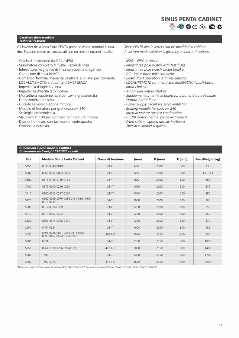
Gli inverter della linea Sinus PENTA possono essere montati in qua-dro. Possono essere personalizzati con un serie di opzioni a scelta.
- Grado di protezione da IP24 a IP54- Sezionatore completo di fusibili rapidi di linea- Interruttore magnetico di linea con bobina di sgancio- Contattore di linea in AC1- Comando frontale mediante selettore a chiave per comando
LOCALE/REMOTO e pulsante d’EMERGENZA- Impedenza d’ingresso linea- Impedenza d’uscita lato motore- Morsettiera supplementare per cavi ingresso/uscita- Filtro toroidale d’uscita- Circuito servoventilazione motore- Modulo di frenatura per grandezza >= S40- Scaldiglia anticondensa- Strumenti PT100 per controllo temperatura motore- Display illuminato con tastiera su fronte quadro- Optional a richiesta
Sinus PENTA line inverters can be provided in cabinet.A custom made solution is given by a choice of options.
- IP24 ÷ IP54 enclosure- Input three pole switch with fast fuses- Input three pole switch circuit breaker- AC1 input three pole contactor- Board front operation with key selector- LOCAL/REMOTE command and EMERGENCY push-botton- Input chokes- Motor side output chokes- Supplementary terminal board for input and output cables- Output ferrite fi lter- Power supply circuit for servoventilation- Braking module for sizes >= S40- Internal resistor against condesation- PT100 motor thermal probe instrument- Front cabinet lighted display keyboard- Special customer requests
Dimensioni e peso modelli CABINETDimensions and weight CABINET models.
Size Modello Sinus Penta Cabinet Classe di tensione L (mm) H (mm) P (mm) Peso/Weight (kg)
S15C 0038-0040-0049 2T-4T 600 2000 500 130
S20C 0060-0067-0074-0086 2T-4T 600 2000 500 140-143
S30C 0113-0129-0150-0162 2T-4T 600 2000 600 162
S40C 0179-0200-0216-0250 2T-4T 1000 2000 600 279
S41C 0180-0202-0217-0260 2T-4T 1000 2000 600 280
S42C 0062-0069-0076-0088-0131-0164 01810218-0259 5T-6T 1000 2000 600 300
S50C 0312-0366-0399 2T-4T 1200 2000 600 350
S51C 0313-0367-0402 2T-4T 1200 2000 600 350
S52C 0290-0314-0368-0401 5T-6T 1200 2000 600 370
S60C 0457-0524 2T-4T 1600 2350 800 586
S65C 0598-0748-0831-0250-0312-03660399-0457-0524-0598-0748 4T-5T-6T 2000 2350 800 854
S70C 0831 5T-6T 2200 2350 800 1007
S75C 0964-1130-1296-0964-1130 4T-5T-6T 3000 2350 800 1468
S80C 1296 5T-6T 3400 2350 800 1700
S90C 1800-2076 4T-5T-6T 4600 2350 800 2300
*Dimensioni e pesi possono variare in funzione degli optional richiesti / *Dimensions and weights may change according to the required optionals.

12
SINUS PENTA
I SINUS sono dimensionati in funzione della corrente e del so-vraccarico ammesso (vedi tabelle LIGHT, STANDARD, HEAVY e STRONG). Ogni singolo modello d’inverter è applicabile a 4 diverse taglie di potenza motore in funzione delle prestazioni richieste dal carico.
The SINUS’s rating performances can be different according to the admitted rated current and overload (look at LIGHT, STAN-DARD, HEAVY and STRONG tables). Every single model of inver-ter can be applied to 4 different sizes of motor power according to the ratings required by the load.
Linea ProdottoProduct LineSINUSSINUS BOXSINUS CABINET
Tipo di controlloControl modePENTA= 5 software a bordo (vedi caratteristiche tecniche) 5 built-in software (see tech. specs.)
Taglia inverterInverter size
AlimentazionePower Supply2= 200~240Vac; 280~340Vdc4= 380~500Vac; 530~705Vdc5= 500~600Vac; 705~845Vdc6= 600~690Vac; 845~970Vdc
Alimentazione Power Supply T= trifase 3 PhaseC= tensione continua direct current supply D= dodecafase 12 impulse bridge
Modulo frenaturaBraking ChopperX= noB= integrato integrated
Filtri EMCEMC Filter I= nessun fi ltro no fi lters A1= EN55011 gr.1 cl.A fi ltro integrato per utenze industriali e domestiche Integrated fi lters for industrial and domestic users A2= EN55011 gr.2 cl.A fi ltro integrato per utenze industriali
Integrated fi lters for industrial users B= EN55011 gr.1 cl.B fi ltro integrato tipo A1 più toroide in uscita per
utenze industriali e domestiche integrated type A1 fi lter and output ferrite ring
for industrial and domestic users
TastieraKeypadX= noK= integrato/integrated
Grado di protezioneEnclosure0= IP002= IP203= IP24 ÷ IP314= IP425= IP54C= condizionatore conditionerS= scambiatore aria-acqua air-water exchanger
Tabelle di selezione prodottoProduct selection chart

13
SINUS PENTA
Scelta Del SovraccaricoOverload Choice
Settori d’impiegoApplications
Sovraccarico/Overload (IST)
Light Standard Heavy Strong
AgitatoreAgitator •
AtomizzatoreAtomizer •
Lava bottiglieBottle washer •
CentrifugaCentrifuge •
SminuzzatoreChipper •
Compressore a pistoni a caricoLoaded piston compressor •
Compressore a pistoni a vuotoUnloaded piston compressor •
Compressore a vite a caricoScrew Compressor loaded •
Compressore a vite a vuotoScrew Compressor unloaded •
Nastro di trasportoConveyor belt • •
RullieraConveyor roller •
CocleaConveyor screw •
Frantumatore a conoCrusher cone •
Frantumatore a mascellaCrusher jaw •
Frantumatore rotativoCrusher rotary •
Frantumatore ad impatto verticaleCrusher vertical impact •
ScortecciatoreDebarker •
EssiccatoreDryer • •
AspiratoreDust collector •
TaglierinaEdger •
Ventilatore assiale con smorzatoreDamped axial fan •
Ventilatore assiale non smorzatoUndamped axial fan •
Ventilatore centrifugo con smorzatoreCentrifugal damped fan •
Ventilatore ad alta pressioneHigh pressure fan •
Ventilatore centrifugo non smorzatoUndamped centrifugal fan •
SollevamentoElevators • •
Traslazione gru e carroponteHoists and cranes’ translation •
CalandreCalenders • •
Presse iniezione, viteScrew injection moulding machines • •
Presse iniezione, centralina idraulicaHydraulic power pack injectionmoulding machines
•
EstrusoriExtruders •
MolaGrinder •
Settori d’impiegoApplications
Sovraccarico/Overload (IST)
Light Standard Heavy Strong
Centralina idraulicaHydraulic power pack •
MulinoMill •
Mulino a sfereBall Mill •
Mulino a martelliHammer Mill •
Mulino rotativiRoller Mill •
MiscelatoreMixer •
PallettizzatorePalletiser • •
PiallatriciPlaners •
Pompe sommerseBore pumps •
Pompe centrifugheCentrifugal pumps •
Pompe a sfasamento positivoPositive displacement pumps •
Pompe fanghiSlurry pumps •
SpappolatorePulper •
Tavolo rotativoRotary table •
LevigatriceSander • •
Sega a nastroBandsaw •
Sega circolareCircular saw •
SeparatoreSeparator •
VibrovaglioVibrating screen •
TrinciatriceShredder •
AffettatriceSlicer •
BottaleTumbler •
Torcitoio/FilatoioTwister/Spinner • •
Lavatrici industrialiIndustrial washers •
TelaiLooms • •
Presse meccanicheMechanical presses • •
MandriniDrills • •
Controllo assiAxe control • •
LaminatoiMills •
Profi latriciForming machines • •
CesoieShears • •
Avvolgitori/SvolgitoriWinding Unwing machines • •
Trafi leDrawplates • •

14
AtomizzatoreLava bottiglieCompressore a vite a vuotoAspiratoreVentilatore assiale con smorzatoreVentilatore assiale non smorzatoVentilatore centrifugo con smorzatore
Ventilatore ad alta pressioneVentilatore centrifugo non smorzatoMolaPompe sommersePompe centrifughePompe a sfasamento positivoPompe fanghi
AtomizerBottle washerScrew Compressor unloadedDust collectorDamped axial fanUndamped axial fanCentrifugal damped fan
High pressure fanUndamped centrifugal fanGrinderBore pumpsCentrifugal pumpsPositive displacement pumpsSlurry pumps
LIGHT OVERLOAD UP TO 144% Tensione di alimentazione fi no a 500 Vca Power supply up to 500 Vac
SINUS PENTA 2T/4T
Modello Model
Potenza motore applicabile/Applicable motor powerInom Imax Ipeak
(3s)200-240Vac 380-415Vac 440-460Vac 480-500Vac
kW HP A kW HP A kW HP A kW HP A A A A
Size S05
SINUS 0005 - - - 4.5 6 9.0 5.5 7.5 9.7 6.5 9 10.2 10.5 11.5 14
SINUS 0007 3 4 11.2 5.5 7.5 11.2 7.5 10 12.5 7.5 10 11.8 12.5 13.5 16
SINUS 0008 3.7 5 13.2 - - - - - - - - - 15 16 19
SINUS 0009 - - - 7.5 10 14.5 9.2 12.5 16 9.2 12.5 14.3 16.5 17.5 19
SINUS 0010 4 5.5 14.6 - - - - - - - - - 17 19 23
SINUS 0011 - - - 7.5 10 14.8 9.2 12.5 16 11 15 16.5 16.5 21 25
SINUS 0013 4.5 6 17.9 - - - - - - - - - 19 21 25
SINUS 0014 - - - 7.5 10 14.8 9.2 12.5 16 11 15 16.5 16.5 25 30
SINUS 0015 5.5 7.5 19.5 - - - - - - - - - 23 25 30
SINUS 0016 7.5 10 25.7 - - - - - - - - - 27 30 36
SINUS 0020 9.2 12.5 30 - - - - - - - - - 30 36 43
Size S12
SINUS 0016 - - - 11 15 21 15 20 25 15 20 23.2 27 30 36
SINUS 0017 - - - 15 20 29 18.5 25 30 18.5 25 28 30 32 37
SINUS 0020 - - - 15 20 29 18.5 25 30 18.5 25 28 30 36 43
SINUS 0023 11 15 36 - - - - - - - - - 38 42 51
SINUS 0025 - - - 22 30 41 22 30 36 22 30 33 41 48 58
SINUS 0030 - - - 22 30 41 22 30 36 25 35 37 41 56 67
SINUS 0033 16 20 50 - - - - - - - - - 51 56 68
SINUS 0034 - - - 30 40 55 30 40 48 37 50 53 57 63 76
SINUS 0036 - - - 30 40 55 37 50 58 37 50 53 60 72 86
SINUS 0037 18.5 25 61 - - - - - - - - - 65 72 83
Size S15
SINUS 0038 18.5 25 61 30 40 55 37 40 58 45 60 64 65 75 88
SINUS 0040 22 30 71 37 50 67 45 60 70 50 70 70 72 80 88
SINUS 0049 25 35 80 45 60 80 50 65 75 55 75 78 80 96 115
Size S20
SINUS 0060 28 38 88 50 70 87 55 75 85 65 90 88 88 112 134
SINUS 0067 30 40 96 55 75 98 65 90 100 75 100 103 103 118 142
SINUS 0074 37 50 117 65 90 114 75 100 116 85 115 120 120 144 173
SINUS 0086 45 60 135 75 100 133 90 125 135 90 125 127 135 155 186
Size S30
SINUS 0113 55 75 170 100 135 180 110 150 166 132 180 180 180 200 240
SINUS 0129 65 90 195 110 150 191 125 170 192 140 190 195 195 215 258
SINUS 0150 70 95 213 120 165 212 132 180 198 150 200 211 215 270 324
SINUS 0162 75 100 231 132 180 228 150 200 230 175 238 240 240 290 324
Tensione alimentazione inverterInverter power supply
200-240 Vac; 280-360Vdc 380-500Vac; 530-705Vdc
*La corrente nominale del motore applicabile non deve essere superiore del 5% rispetto alla “Inom.”1) In questi modelli è obbligatorio l’utilizzo dell’induttanza di uscita.Legenda Inom= corrente nominale continuativa dell’inverter • Imax= corrente massima erogabile dall’inverter per 120sec ogni 20min fi no a S30 e 60sec ogni 10min >= S40 • Ipeak= corrente erogabi-le per un massimo di 3 sec
*The applicable nominal motor current shall not be higher than 5% of “Inom.”1) In these models output choke is requiredCaption Inom= inverter nominal current • Imax= inverter maximum current for 120sec every 20min. till S30 and 60sec. every 10min. >= S40 (overload 120%) • Ipeak= inverter maximum current for 3sec

15
SINUS PENTA 2T/4T
ModelloModel
Potenza motore applicabile/Applicable motor powerInom Imax Ipeak
(3s)200-240Vac 380-415Vac 440-460Vac 480-500Vac
kW HP A kW HP A kW HP A kW HP A A A A
Size S41
SINUS 0180 90 125 277 160 220 273 200 270 297 220 300 300 300 340 408
SINUS 0202 110 150 332 200 270 341 220 300 326 250 340 337 345 420 504
SINUS 0217 120 165 375 220 300 375 250 340 366 260 350 359 375 460 552
SINUS 0260 132 180 390 250 340 425 280 380 410 300 410 418 425 560 672
Size S51
SINUS 0313 160 220 475 280 380 480 315 430 459 355 485 471 480 600 720
SINUS 0367 185 250 550 315 430 528 375 510 540 400 550 544 550 680 792
SINUS 0402 230 315 675 400 550 680 450 610 665 500 680 673 680 850 1020
Size S60
SINUS 0457 250 340 732 400 550 680 450 610 665 500 680 673 720 880 1056
SINUS 0524 260 350 780 450 610 765 500 680 731 560 760 751 800 960 1152
Size S651)
SINUS 0598 - - - 500 680 841 560 760 817 630 860 864 900 1100 1320
SINUS 0748 - - - 560 760 939 630 860 939 710 970 960 1000 1300 1560
SINUS 0831 - - - 710 970 1200 800 1090 1160 900 1230 1184 1200 1440 1728
Size S751)
SINUS 0964 - - - 900 1230 1480 1000 1360 1431 1100 1500 1480 1480 1780 2136
SINUS 1130 - - - 1000 1360 1646 1170 1600 1700 1270 1730 1700 1700 2040 2448
SINUS 1296 - - - 1200 1650 2050 1400 1830 2000 1460 1990 2050 2100 2520 3024
Size S901)
SINUS 1800 - - - 1500 2000 2500 1750 2400 2500 1850 2500 2500 2600 3100 3720
SINUS 2076 - - - 1750 2400 2900 2000 2720 2900 2100 2900 2900 3000 3600 4320
Tensione alimentazione inverterInverter power supply
200-240 Vac; 280-360Vdc 380-500Vac; 530-705Vdc
*La corrente nominale del motore applicabile non deve essere superiore del 5% rispetto alla “Inom.”1) In questi modelli è obbligatorio l’utilizzo dell’induttanza di uscita.Legenda Inom= corrente nominale continuativa dell’inverter • Imax= corrente massima erogabile dall’inverter per 120sec ogni 20min fi no a S30 e 60sec ogni 10min >= S40 • Ipeak= corrente erogabi-le per un massimo di 3 sec
*The applicable nominal motor current shall not be higher than 5% of “Inom.”1) In these models output choke is requiredCaption Inom= inverter nominal current • Imax= inverter maximum current for 120sec every 20min. till S30 and 60sec. every 10min. >= S40 (overload 120%) • Ipeak= inverter maximum current for 3sec

16
STANDARD OVERLOAD UP TO 168%Tensione di alimentazione fi no a 500 Vca Power supply up to 500 Vac
SINUS PENTA 2T/4T
AgitatoreCentrifugaSminuzzatoreCompressore a pistoni a vuotoCompressore a vite a caricoNastro di trasportoRullieraFrantumatore a conoFrantumatore rotativoFrantumatore ad impatto verticaleScortecciatoreEssiccatoreTaglierinaCalandrePresse iniezione, viteEstrusoriCentralina idraulicaMiscelatore
PallettizzatorePompe fanghiTavolo rotativoLevigatriceSega a nastroSega circolareSeparatoreTrinciatriceAffettatriceBottaleTorcitoio/FilatoioLavatrici industrialiPresse meccanicheProfi latriciCesoieAvvolgitori/SvolgitoriTrafi le
AgitatorCentrifugeChipperUnloaded piston compressorScrew Compressor loadedConveyor beltConveyor rollerCrusher coneaCrusher rotaryCrusher vertical impactDebarkerDryerEdgerCalendersScrew injection moulding machinesExtrudersHydraulic power packMixer
PalletiserSlurry pumpsRotary tableSanderBandsawCircular sawSeparatorShredderSlicerTumblerTwister/SpinnerIndustrial washersMechanical pressesForming machinesShearsWinding Unwing machinesDrawplates
ModelloModel
Potenza motore applicabile/Applicable motor powerInom Imax Ipeak
(3s)200-240Vac 380-415Vac 440-460Vac 480-500Vac
kW HP A kW HP A kW HP A kW HP A A A A
Size S05
SINUS 0005 - - - 4 5.5 8.4 4.5 6 7.8 5.5 7.5 9.0 10.5 11.5 14
SINUS 0007 2.2 3 8.5 4.5 6 9.0 5.5 7.5 9.7 6.5 9 10.2 12.5 13.5 16
SINUS 0008 3 4 11.2 - - - - - - - - - 15 16 19
SINUS 0009 - - - 5.5 7.5 11.2 7.5 10 12.5 7.5 10 11.8 16.5 17.5 19
SINUS 0010 3.7 5 13.2 - - - - - - - - - 17 19 23
SINUS 0011 - - - 7.5 10 14.8 9.2 12.5 15.6 9.2 12.5 14.3 16.5 21 25
SINUS 0013 4 5.5 14.6 - - - - - - - - - 19 21 25
SINUS 0014 - - - 7.5 10 14.8 9.2 12.5 15.6 11 15 16.5 16.5 25 30
SINUS 0015 4.5 6 17.9 - - - - - - - - - 23 25 30
SINUS 0016 5.5 7.5 19.5 - - - - - - - - - 27 30 36
SINUS 0020 7.5 10 25.7 - - - - - - - - - 30 36 43
Size S12
SINUS 0016 - - - 9.2 12.5 17.9 11 15 18.3 15 20 23.2 27 30 36
SINUS 0017 - - - 11 15 21 11 15 18.3 15 20 23.2 30 32 37
SINUS 0020 - - - 15 20 29 15 20 25 18.5 25 28 30 36 43
SINUS 0023 9.2 12.5 30 - - - - - - - - - 38 42 51
SINUS 0025 - - - 18.5 25 35 18.5 25 30 22 30 33 41 48 58
SINUS 0030 - - - 22 30 41 22 30 36 25 35 37 41 56 67
SINUS 0033 16 20 50 - - - - - - - - - 51 56 68
SINUS 0034 - - - 25 35 46 30 40 48 30 40 44 57 63 76
SINUS 0036 - - - 30 40 55 30 40 48 37 50 53 60 72 86
SINUS 0037 15 20 50 - - - - - - - - - 65 72 83
Size S15
SINUS 0038 15 20 50 25 35 46 30 40 48 37 50 53 65 75 88
SINUS 0040 18.5 25 61 30 40 55 37 50 58 40 55 58 72 80 88
SINUS 0049 22 30 71 37 50 67 45 60 70 45 60 64 80 96 115
Size S20
SINUS 0060 25 35 80 45 60 80 55 75 85 55 75 78 88 112 134
SINUS 0067 30 40 96 55 75 98 65 90 100 75 100 103 103 118 142
SINUS 0074 37 50 117 65 90 114 70 95 107 75 100 103 120 144 173
SINUS 0086 40 55 127 75 100 133 75 100 116 85 115 120 135 155 186
Tensione alimentazione inverterInverter power supply
200-240 Vac; 280-360Vdc 380-500Vac; 530-705Vdc
*La corrente nominale del motore applicabile non deve essere superiore del 5% rispetto alla “Inom.”1) In questi modelli è obbligatorio l’utilizzo dell’induttanza di uscita.Legenda Inom= corrente nominale continuativa dell’inverter • Imax= corrente massima erogabile dall’inverter per 120sec ogni 20min fi no a S30 e 60sec ogni 10min >= S40 • Ipeak= corrente erogabi-le per un massimo di 3 sec
*The applicable nominal motor current shall not be higher than 5% of “Inom.”1) In these models output choke is requiredCaption Inom= inverter nominal current • Imax= inverter maximum current for 120sec every 20min. till S30 and 60sec. every 10min. >= S40 (overload 120%) • Ipeak= inverter maximum current for 3sec

17
SINUS PENTA 2T/4T
ModelloModel
Potenza motore applicabile/Applicable motor powerInom Imax Ipeak
(3s)200-240Vac 380-415Vac 440-460Vac 480-500Vac
kW HP A kW HP A kW HP A kW HP A A A A
Size S30
SINUS 0113 45 60 135 90 125 159 90 125 135 90 125 127 180 200 240
SINUS 0129 55 75 170 100 135 180 110 150 166 110 150 153 195 215 258
SINUS 0150 65 90 195 110 150 191 132 180 198 150 200 211 215 270 324
SINUS 0162 75 100 231 132 180 228 150 200 230 160 220 218 240 290 324
Size S41
SINUS 0180 80 110 250 150 200 264 185 250 279 200 270 273 300 340 408
SINUS 0202 90 125 277 160 220 273 220 300 326 250 340 337 345 420 504
SINUS 0217 110 150 332 220 270 375 250 340 375 260 350 359 375 460 552
SINUS 0260 132 180 390 250 340 425 280 380 410 300 410 418 425 560 672
Size S51
SINUS 0313 160 220 475 280 380 480 315 430 459 355 485 471 480 600 720
SINUS 0367 185 250 550 315 430 528 375 510 540 400 550 544 550 680 792
SINUS 0402 230 315 675 400 550 680 450 610 665 500 680 673 680 850 1020
Size S60
SINUS 0457 220 300 661 400 550 680 450 610 665 500 680 673 720 880 1056
SINUS 0524 260 350 780 450 610 765 500 680 731 560 770 751 800 960 1152
Size S651)
SINUS 0598 - - - 500 680 841 560 760 817 630 860 864 900 1100 1320
SINUS 0748 - - - 560 760 939 630 860 939 710 970 960 1000 1300 1560
SINUS 0831 - - - 630 860 1080 800 1090 1160 800 1090 1067 1200 1440 1728
Size S751)
SINUS 0964 - - - 800 1090 1334 900 1230 1287 1000 1360 1317 1480 1780 2136
SINUS 1130 - - - 900 1230 1480 1100 1500 1630 1170 1600 1570 1700 2040 2448
SINUS 1296 - - - 1200 1650 2050 1400 1830 2000 1460 1990 2050 2100 2520 3024
Size S901)
SINUS 1800 - - - 1400 1910 2400 1700 2300 2400 1750 2400 2400 2600 3100 3720
SINUS 2076 - - - 1750 2400 2900 2000 2720 2900 2100 2900 2900 3000 3600 4320
Tensione alimentazione inverterInverter power supply
200-240 Vac; 280-360Vdc 380-500Vac; 530-705Vdc
*La corrente nominale del motore applicabile non deve essere superiore del 5% rispetto alla “Inom.”1) In questi modelli è obbligatorio l’utilizzo dell’induttanza di uscita.Legenda Inom= corrente nominale continuativa dell’inverter • Imax= corrente massima erogabile dall’inverter per 120sec ogni 20min fi no a S30 e 60sec ogni 10min >= S40 • Ipeak= corrente erogabi-le per un massimo di 3 sec
*The applicable nominal motor current shall not be higher than 5% of “Inom.”1) In these models output choke is requiredCaption Inom= inverter nominal current • Imax= inverter maximum current for 120sec every 20min. till S30 and 60sec. every 10min. >= S40 (overload 120%) • Ipeak= inverter maximum current for 3sec

18
HEAVY OVERLOAD UP TO 210% Tensione di alimentazione fi no a 500 Vca Power supply up to 500 Vac
SINUS PENTA 2T/4T
ModelloModel
Potenza motore applicabile/Applicable motor powerInom Imax Ipeak
(3s)200-240Vac 380-415Vac 440-460Vac 480-500Vac
kW HP A kW HP A kW HP A kW HP A A A A
Size S05
SINUS 0005 - - - 3 4 6.4 3.7 5 6.6 4.5 6 7.2 10.5 11.5 14
SINUS 0007 1.8 2.5 7.3 4 5.5 8.4 4.5 6 7.8 5.5 7.5 9.0 12.5 13.5 16
SINUS 0008 2.2 3 8.5 - - - - - - - - - 15 16 19
SINUS 0009 - - - 4.5 6 9.0 5.5 7.5 9.7 7.5 10 11.8 16.5 17.5 19
SINUS 0010 3 4 11.2 - - - - - - - - - 17 19 23
SINUS 0011 - - - 5.5 7.5 11.2 7.5 10 12.5 9.2 12.5 14.3 16.5 21 25
SINUS 0013 3.7 5 13.2 - - - - - - - - - 19 21 25
SINUS 0014 - - - 7.5 10 14.8 9.2 12.5 15.6 11 15 16.5 16.5 25 30
SINUS 0015 4 5.5 16.6 - - - - - - - - - 23 25 30
SINUS 0016 4.5 6 17.9 - - - - - - - - - 27 30 36
SINUS 0020 5.5 7.5 19.5 - - - - - - - - - 30 36 43
Size S12
SINUS 0016 - - - 9.2 12.5 17.9 11 15 18.3 12.5 17 18.9 27 30 36
SINUS 0017 - - - 9.2 12.5 17.9 11 15 18.3 12.5 17 18.9 30 32 37
SINUS 0020 - - - 11 15 21 15 20 25 15 20 23.2 30 36 43
SINUS 0023 7.5 10 25.7 - - - - - - - - - 38 42 51
SINUS 0025 - - - 15 20 29 18.5 25 30 18.5 25 28 41 48 58
SINUS 0030 - - - 18.5 25 35 22 30 36 22 30 33 41 56 67
SINUS 0033 11 15 36 - - - - - - - - - 51 56 68
SINUS 0034 - - - 22 30 41 25 35 40 28 38 41 57 63 76
SINUS 0036 - - - 25 35 46 30 40 48 30 40 44 60 72 86
SINUS 0037 15 20 50 - - - - - - - - - 65 72 83
Size S15
SINUS 0038 15 20 50 25 35 46 30 40 48 30 40 44 65 75 88
SINUS 0040 15 20 50 25 35 46 30 40 48 37 50 53 72 80 88
SINUS 0049 18.5 25 61 30 40 55 37 50 58 45 60 64 80 96 115
Size S20
SINUS 0060 22 30 71 37 50 67 45 60 70 50 70 70 88 112 134
SINUS 0067 25 35 80 45 60 80 50 70 75 55 75 78 103 118 142
SINUS 0074 30 40 96 50 70 87 55 75 85 65 90 88 120 144 173
SINUS 0086 32 45 103 55 75 98 65 90 100 75 100 103 135 155 186
Tensione alimentazione inverterInverter power supply
200-240 Vac; 280-360Vdc 380-500Vac; 530-705Vdc
Compressore a pistoni a caricoNastro di trasportoCocleaFrantumatore a mascellaEssiccatoreSollevamentoTraslazione gru e carroponteCalandrePresse iniezione, vitePresse iniezione, centralina idraulicaMulinoMulino a sfereMulino a martelliMulino rotativi
PiallatriciSpappolatoreVibrovaglioAffettatriceBottaleTelaiPresse meccanicheMandriniControllo assiLaminatoiProfi latriciCesoieAvvolgitori/SvolgitoriTrafi le
Loaded piston compressorConveyor beltConveyor screwCrusher jawDryerElevatorsHoists and cranes’ translationCalendersScrew injection moulding machinesHydraulic power pack injectionmoul-ding machinesMillBall MillHammer MillRoller Mill
PlanersPulperVibrating screenSlicerTumblerLoomsMechanical pressesDrillsAxe controlMillsForming machinesShearsWinding Unwing machinesDrawplates
*La corrente nominale del motore applicabile non deve essere superiore del 5% rispetto alla “Inom.”1) In questi modelli è obbligatorio l’utilizzo dell’induttanza di uscita.Legenda Inom= corrente nominale continuativa dell’inverter • Imax= corrente massima erogabile dall’inverter per 120sec ogni 20min fi no a S30 e 60sec ogni 10min >= S40 • Ipeak= corrente erogabi-le per un massimo di 3 sec
*The applicable nominal motor current shall not be higher than 5% of “Inom.”1) In these models output choke is requiredCaption Inom= inverter nominal current • Imax= inverter maximum current for 120sec every 20min. till S30 and 60sec. every 10min. >= S40 (overload 120%) • Ipeak= inverter maximum current for 3sec

19
ModelloModel
Potenza motore applicabile/Applicable motor powerInom Imax Ipeak
(3s)200-240Vac 380-415Vac 440-460Vac 480-500Vac
kW HP A kW HP A kW HP A kW HP A A A A
Size S30
SINUS 0113 45 60 135 75 100 133 75 100 116 90 125 127 180 200 240
SINUS 0129 50 70 150 80 110 144 90 125 135 110 150 153 195 215 258
SINUS 0150 55 75 170 90 125 159 110 150 166 132 180 180 215 270 324
SINUS 0162 65 90 195 110 150 191 132 180 198 140 190 191 240 290 324
Size S41
SINUS 0180 75 100 231 132 180 228 160 220 237 160 220 218 300 340 408
SINUS 0202 90 125 277 160 220 273 185 250 279 200 270 273 345 420 504
SINUS 0217 110 150 332 185 250 321 220 300 326 220 300 300 375 460 552
SINUS 0260 132 180 390 220 300 375 260 350 390 280 380 393 425 560 672
Size S51
SINUS 0313 132 180 390 250 340 421 260 350 390 300 400 413 480 600 720
SINUS 0367 160 220 475 280 380 480 315 430 459 355 485 471 550 680 792
SINUS 0402 185 250 550 355 485 589 400 550 576 400 550 544 680 850 1020
Size S60
SINUS 0457 200 270 593 315 430 528 375 510 540 450 610 612 720 880 1056
SINUS 0524 220 300 661 355 480 589 450 610 665 500 680 673 800 960 1152
Size S651)
SINUS 0598 - - - 400 550 680 500 680 731 560 760 751 900 1100 1320
SINUS 0748 - - - 500 680 841 560 760 817 630 860 864 1000 1300 1560
SINUS 0831 - - - 560 760 939 630 860 939 710 970 960 1200 1440 1728
Size S751)
SINUS 0964 - - - 710 970 1200 800 1090 1160 900 1230 1184 1480 1780 2136
SINUS 1130 - - - 800 1090 1334 900 1230 1287 1000 1360 1317 1700 2040 2448
SINUS 1296 - - - 1000 1360 1650 1100 1500 1630 1170 1600 1560 2100 2520 3024
Size S901)
SINUS 1800 - - - 1200 1650 2050 1450 1970 2050 1500 2000 2050 2600 3100 3720
SINUS 2076 - - - 1400 1910 2400 1700 2300 2400 1750 2400 2400 3000 3600 4320
Tensione alimentazione inverterInverter power supply
200-240 Vac; 280-360Vdc 380-500Vac; 530-705Vdc
SINUS PENTA 2T/4T
*La corrente nominale del motore applicabile non deve essere superiore del 5% rispetto alla “Inom.”1) In questi modelli è obbligatorio l’utilizzo dell’induttanza di uscita.Legenda Inom= corrente nominale continuativa dell’inverter • Imax= corrente massima erogabile dall’inverter per 120sec ogni 20min fi no a S30 e 60sec ogni 10min >= S40 • Ipeak= corrente erogabi-le per un massimo di 3 sec
*The applicable nominal motor current shall not be higher than 5% of “Inom.”1) In these models output choke is requiredCaption Inom= inverter nominal current • Imax= inverter maximum current for 120sec every 20min. till S30 and 60sec. every 10min. >= S40 (overload 120%) • Ipeak= inverter maximum current for 3sec

20
STRONG OVERLOAD UP TO 240% Tensione di alimentazione fi no a 500 Vca Power supply up to 500 Vac
SINUS PENTA 2T/4T
ModelloModel
Potenza motore applicabile/Applicable motor powerInom Imax Ipeak
(3s)200-240Vac 380-415Vac 440-460Vac 480-500Vac
kW HP A kW HP A kW HP A kW HP A A A A
Size S05
SINUS 0005 - - - 2.2 3 4.9 3 4 5.6 3.7 5 6.1 10.5 11.5 14
SINUS 0007 1.5 2 6.1 3 4 6.4 3.7 5 6.6 4.5 6 7.2 12.5 13.5 16
SINUS 0008 1.8 2.5 7.3 - - - - - - - - - 15 16 19
SINUS 0009 - - - 4 5.5 8.4 4.5 6 7.8 5.5 7.5 9.0 16.5 17.5 19
SINUS 0010 2.2 3 8.5 - - - - - - - - - 17 19 23
SINUS 0011 - - - 4.5 6 9.0 5.5 7.5 9.7 7.5 10 11.8 16.5 21 25
SINUS 0013 3 4 11.2 - - - - - - - - - 19 21 25
SINUS 0014 - - - 5.5 7.5 11.2 7.5 10 12.5 9.2 12.5 14.3 16.5 25 30
SINUS 0015 3.7 5 13.2 - - - - - - - - - 23 25 30
SINUS 0016 4 5.5 16.6 - - - - - - - - - 27 30 36
SINUS 0020 4.5 6 17.9 - - - - - - - - - 30 36 43
Size S12
SINUS 0016 - - - 7.5 10 14.8 9.2 12.5 15.6 11 15 16.5 27 30 36
SINUS 0017 - - -- 7.5 10 14.8 9.2 12.5 15.6 12.5 17 18.9 30 32 37
SINUS 0020 - - - 9.2 12.5 17.9 11 15 18.3 12.5 17 18.9 30 36 43
SINUS 0023 5.5 7.5 19.5 - - - - - - - - - 38 42 51
SINUS 0025 - - - 11 15 21 15 20 25 15 20 23.2 41 48 58
SINUS 0030 - - - 15 20 29 18.5 25 30 18.5 25 28 41 56 67
SINUS 0033 7.5 10 25.7 - - - - - - - - - 51 56 68
SINUS 0034 - - - 18.5 25 35 22 30 36 22 30 33 57 63 76
SINUS 0036 - - - 22 30 41 25 35 40 28 38 41 60 72 86
SINUS 0037 11 15 36 - - - - - - - - - 65 72 83
Size S15
SINUS 0038 12.5 17 41 22 30 41 25 35 40 28 38 41 65 75 88
SINUS 0040 12.5 17 41 22 30 41 25 35 40 30 40 44 72 80 88
SINUS 0049 15 20 50 25 35 46 30 40 48 37 50 53 80 96 115
Size S20
SINUS 0060 18.5 25 61 30 40 55 37 50 58 45 60 64 88 112 134
SINUS 0067 20 27 66 32 45 59 40 55 63 50 70 70 103 118 142
SINUS 0074 22 30 71 37 50 67 45 60 70 55 75 78 120 144 173
SINUS 0086 25 35 80 45 60 80 55 75 85 65 90 88 135 155 186
Size S30
SINUS 0113 30 40 96 55 75 98 65 88 100 75 100 103 180 200 240
SINUS 0129 37 50 117 65 90 114 75 100 116 85 115 120 195 215 258
SINUS 0150 45 60 135 75 100 133 90 125 135 90 125 127 215 270 324
SINUS 0162 55 75 170 90 125 159 110 150 166 110 150 153 240 290 324
Size S41
SINUS 0180 60 85 185 110 150 191 120 165 184 132 180 300 300 340 408
SINUS 0202 75 100 231 132 180 228 150 200 230 160 220 345 345 420 504
SINUS 0217 75 100 231 150 200 260 160 220 245 185 250 375 375 460 552
SINUS 0260 90 125 277 185 250 321 200 270 307 200 270 425 425 560 672
Tensione alimentazione inverterInverter power supply
200-240 Vac;280-360Vdc 380-500Vac; 530-705Vdc
SollevamentoPresse iniezione, centralina idraulica
MandriniControllo assi
LiftingInjection presses, hydraulic power pack
ChucksAxis control
*La corrente nominale del motore applicabile non deve essere superiore del 5% rispetto alla “Inom.”1) In questi modelli è obbligatorio l’utilizzo dell’induttanza di uscita.Legenda Inom= corrente nominale continuativa dell’inverter • Imax= corrente massima erogabile dall’inverter per 120sec ogni 20min fi no a S30 e 60sec ogni 10min >= S40 • Ipeak= corrente erogabi-le per un massimo di 3 sec
*The applicable nominal motor current shall not be higher than 5% of “Inom.”1) In these models output choke is requiredCaption Inom= inverter nominal current • Imax= inverter maximum current for 120sec every 20min. till S30 and 60sec. every 10min. >= S40 (overload 120%) • Ipeak= inverter maximum current for 3sec

21
ModelloModel
Potenza motore applicabile/Applicable motor powerInom Imax Ipeak
(3s)200-240Vac 380-415Vac 440-460Vac 480-500Vac
kW HP A kW HP A kW HP A kW HP A A A A
Size S51
SINUS 0313 110 150 332 200 270 341 220 300 326 250 340 337 480 600 720
SINUS 0367 120 165 375 220 300 375 250 340 366 260 350 359 550 680 792
SINUS 0402 160 220 475 280 380 480 315 430 462 355 480 471 680 850 1020
Size S60
SINUS 0457 160 220 475 280 380 480 330 450 493 375 510 497 720 880 1056
SINUS 0524 185 250 550 315 430 528 375 510 540 400 550 544 800 960 1152
Size S651)
SINUS 0598 - - - 355 480 589 400 550 591 450 610 612 900 1100 1320
SINUS 0748 - - - 400 550 680 500 680 731 560 760 751 1000 1300 1560
SINUS 0831 - - - 450 610 765 560 760 817 630 860 864 1200 1440 1728
Size S751)
SINUS 0964 - - - 560 770 939 710 970 1043 800 1090 1067 1480 1780 2136
SINUS 1130 - - - 710 970 1200 800 1090 1160 900 1230 1184 1700 2040 2448
SINUS 1296 - - - 800 1090 1334 900 1230 1287 1000 1360 1317 2100 2520 3024
Size S901)
SINUS 1800 - - - 1000 1360 1650 1170 1600 1650 1200 1650 1650 2600 3100 3720
SINUS 2076 - - - 1200 1650 2050 1450 1970 2050 1500 2000 2050 3000 3600 4320
Tensione alimentazione inverterInverter power supply
200-240 Vac; 280-360Vdc 380-500Vac; 530-705Vdc
SINUS PENTA 2T/4T
*La corrente nominale del motore applicabile non deve essere superiore del 5% rispetto alla “Inom.”1) In questi modelli è obbligatorio l’utilizzo dell’induttanza di uscita.Legenda Inom= corrente nominale continuativa dell’inverter • Imax= corrente massima erogabile dall’inverter per 120sec ogni 20min fi no a S30 e 60sec ogni 10min >= S40 • Ipeak= corrente erogabi-le per un massimo di 3 sec
*The applicable nominal motor current shall not be higher than 5% of “Inom.”1) In these models output choke is requiredCaption Inom= inverter nominal current • Imax= inverter maximum current for 120sec every 20min. till S30 and 60sec. every 10min. >= S40 (overload 120%) • Ipeak= inverter maximum current for 3sec

22
ModelloModel
Potenza motore applicabile/Applicable motor powerInom. Imax Ipeak
(3 sec.) 575Vac 660-690Vac
kW HP A kW HP A A A A
Size S05 5T - Size S14 6T
SINUS PENTA 0003 5,5 5,7 5,5 7,5 6,3 7 8,5 10 10
SINUS PENTA 0004 7,5 7,6 7,5 10 8,4 9 11 13 13
SINUS PENTA 0006 10 10 7,5 10 8,4 11 13,5 16 16
SINUS PENTA 0012 12,5 12,5 11 15 12,1 13 16 19 19
SINUS PENTA 0018 15 14 15 20 16,8 17 21 25 25
Size S14
SINUS PENTA 0019 15 20 20 15 20 16,8 21 25 30
SINUS PENTA 0021 18,5 25 25 22 30 23 25 30 36
SINUS PENTA 0022 22 30 28 30 40 33 33 40 48
SINUS PENTA 0024 30 40 39 37 50 39 40 48 58
SINUS PENTA 0032 37 50 47 45 60 46 52 63 76
Size S22
SINUS PENTA 0042 45 60 55 55 75 56 60 72 86
SINUS PENTA 0051 55 75 70 75 100 78 80 96 115
SINUS PENTA 0062 65 90 83 75 100 78 85 110 132
SINUS PENTA 0069 90 125 115 90 125 94 105 135 162
Size S32
SINUS PENTA 0076 90 125 115 110 150 113 125 165 198
SINUS PENTA 0088 110 150 135 132 180 133 150 200 240
SINUS PENTA 0131 132 180 168 185 250 185 190 250 300
SINUS PENTA 0164 160 220 198 220 300 220 230 300 360
SINUS PENTA 0172 200 270 240 250 340 250 265 345 414
Size S42
SINUS PENTA 0181 220 300 275 250 340 250 290 380 456
SINUS PENTA 0201 250 340 300 315 430 310 330 420 504
SINUS PENTA 0218 300 400 358 355 480 350 360 465 558
SINUS PENTA 0259 330 450 395 400 550 390 400 560 672
Size S52
SINUS PENTA 0290 355 480 420 450 610 440 450 600 720
SINUS PENTA 0314 400 550 480 500 680 480 500 650 780
SINUS PENTA 0368 450 610 532 560 770 544 560 720 864
SINUS PENTA 0401 560 770 630 630 860 626 640 850 1020
Size S65
SINUS PENTA 0457 630 860 720 710 970 696 720 880 1056
SINUS PENTA 0524 710 970 800 800 1090 773 800 960 1152
SINUS PENTA 0598 800 1090 900 900 1230 858 900 1100 1320
SINUS PENTA 0748 900 1230 1000 1000 1360 954 1000 1300 1560
Tensione alimentazione inverter Inverter power supply 500-600Vac; 705-845Vdc 600-690Vac; 845-970Vdc
LIGHT OVERLOAD UP TO 144%Tensione di alimentazione da 525 a 690 Vca Power supply up to 525 to 690 Vac
SINUS PENTA 5T/6T
AtomizzatoreLava bottiglieCompressore a vite a vuotoAspiratoreVentilatore assiale con smorzatoreVentilatore assiale non smorzatoVentilatore centrifugo con smorzatore
Ventilatore ad alta pressioneVentilatore centrifugo non smorzatoMolaPompe sommersePompe centrifughePompe a sfasamento positivoPompe fanghi
AtomizerBottle washerScrew Compressor unloadedDust collectorDamped axial fanUndamped axial fanCentrifugal damped fan
High pressure fanUndamped centrifugal fanGrinderBore pumpsCentrifugal pumpsPositive displacement pumpsSlurry pumps
*La corrente nominale del motore applicabile non deve essere superiore del 5% rispetto alla “Inom.”1) In questi modelli è obbligatorio l’utilizzo dell’induttanza di uscita.Legenda Inom= corrente nominale continuativa dell’inverter • Imax= corrente massima erogabile dall’inverter per 60sec ogni 10min • Ipeak= corrente erogabile per un massimo di 3 sec
*The applicable nominal motor current shall not be higher than 5% of “Inom.”1) In these models output choke is requiredCaption Inom= inverter nominal current • Imax= inverter maximum current for 60sec every 10min • Ipeak= inverter maximum current for 3sec

23
ModelloModel
Potenza motore applicabile/Applicable motor powerInom. Imax Ipeak
(3 sec.) 575Vac 660-690Vac
kW HP A kW HP A A A A
Size S70
SINUS PENTA 0831 1000 1360 1145 1240 1690 1200 1200 1440 1728
Size S75
SINUS PENTA 0964 1270 1730 1480 1530 2090 1480 1480 1780 2136
SINUS PENTA 1130 1460 1990 1700 1750 2380 1700 1700 2040 2448
Size S80
SINUS PENTA 1296 1670 2280 1950 2010 2740 1950 2100 2520 3024
Size S90
SINUS PENTA 1800 2000 2720 2400 2400 3300 2400 2600 3100 3720
SINUS PENTA 2076 2500 3400 3000 3000 4000 3000 3000 3600 4320
Tensione alimentazione inverter Inverter power supply 500-600Vac; 705-845Vdc 600-690Vac; 845-970Vdc
*La corrente nominale del motore applicabile non deve essere superiore del 5% rispetto alla “Inom.”1) In questi modelli è obbligatorio l’utilizzo dell’induttanza di uscita.Legenda Inom= corrente nominale continuativa dell’inverter • Imax= corrente massima erogabile dall’inverter per 60sec ogni 10min • Ipeak= corrente erogabile per un massimo di 3 sec
*The applicable nominal motor current shall not be higher than 5% of “Inom.”1) In these models output choke is requiredCaption Inom= inverter nominal current • Imax= inverter maximum current for 60sec every 10min • Ipeak= inverter maximum current for 3sec
SINUS PENTA 5T/6T

24
STANDARD OVERLOAD UP TO 168%Tensione di alimentazione da 525 a 690 Vca Power supply up to 525 to 690 Vac
AgitatoreCentrifugaSminuzzatoreCompressore a pistoni a vuotoCompressore a vite a caricoNastro di trasportoRullieraFrantumatore a conoFrantumatore rotativoFrantumatore ad impatto verticaleScortecciatoreEssiccatoreTaglierinaCalandrePresse iniezione, viteEstrusoriCentralina idraulicaMiscelatore
PallettizzatorePompe fanghiTavolo rotativoLevigatriceSega a nastroSega circolareSeparatoreTrinciatriceAffettatriceBottaleTorcitoio/FilatoioLavatrici industrialiPresse meccanicheProfi latriciCesoieAvvolgitori/SvolgitoriTrafi le
AgitatorCentrifugeChipperUnloaded piston compressorScrew Compressor loadedConveyor beltConveyor rollerCrusher coneaCrusher rotaryCrusher vertical impactDebarkerDryerEdgerCalendersScrew injection moulding machinesExtrudersHydraulic power packMixer
PalletiserSlurry pumpsRotary tableSanderBandsawCircular sawSeparatorShredderSlicerTumblerTwister/SpinnerIndustrial washersMechanical pressesForming machinesShearsWinding Unwing machinesDrawplates
SINUS PENTA 5T/6T
ModelloModel
Potenza motore applicabile/Applicable motor powerInom. Imax Ipeak
(3 sec.) 575Vac 660-690Vac
kW HP A kW HP A A A A
Size S05 5T - Size S14 6T
SINUS PENTA 0003 4 5,5 5,7 4 5,5 4,8 7 8,5 10
SINUS PENTA 0004 5,5 7,5 7,6 5,5 7,5 6,3 9 11 13
SINUS PENTA 0006 7,5 10 10 7,5 10 8,4 11 13,5 16
SINUS PENTA 0012 7,5 10 10 7,5 10 8,4 13 16 19
SINUS PENTA 0018 11 15 14 11 15 12,1 17 21 25
Size S14
SINUS PENTA 0019 11 15 14 11 15 12,1 21 25 30
SINUS PENTA 0021 15 20 20 18,5 25 21 25 30 36
SINUS PENTA 0022 22 30 28 22 30 23 33 40 48
SINUS PENTA 0024 25 35 32 30 40 33 40 48 58
SINUS PENTA 0032 37 50 47 37 50 39 52 63 76
Size S22
SINUS PENTA 0042 45 60 55 45 60 46 60 72 86
SINUS PENTA 0051 55 75 70 55 75 56 80 96 115
SINUS PENTA 0062 55 75 70 75 100 78 85 110 132
SINUS PENTA 0069 75 100 95 90 125 94 105 135 162
Size S32
SINUS PENTA 0076 90 125 115 90 125 94 125 165 198
SINUS PENTA 0088 110 150 135 132 180 133 150 200 240
SINUS PENTA 0131 132 180 168 160 220 158 190 250 300
SINUS PENTA 0164 160 220 198 200 270 198 230 300 360
SINUS PENTA 0172 185 250 225 220 300 220 265 345 414
Size S42
SINUS PENTA 0181 220 300 275 250 340 250 290 380 456
SINUS PENTA 0201 250 340 300 315 430 310 330 420 504
SINUS PENTA 0218 300 400 358 315 430 310 360 465 558
SINUS PENTA 0259 330 450 395 400 550 390 400 560 672
Size S52
SINUS PENTA 0290 355 480 420 450 610 440 450 600 720
SINUS PENTA 0314 400 550 480 450 610 450 500 650 780
SINUS PENTA 0368 450 610 532 500 680 480 560 720 864
SINUS PENTA 0401 450 610 532 630 860 626 640 850 1020
Tensione alimentazione inverter Inverter power supply 500-600Vac; 705-845Vdc 600-690Vac; 845-970Vdc
*La corrente nominale del motore applicabile non deve essere superiore del 5% rispetto alla “Inom.”1) In questi modelli è obbligatorio l’utilizzo dell’induttanza di uscita.Legenda Inom= corrente nominale continuativa dell’inverter • Imax= corrente massima erogabile dall’inverter per 60sec ogni 10min • Ipeak= corrente erogabile per un massimo di 3 sec
*The applicable nominal motor current shall not be higher than 5% of “Inom.”1) In these models output choke is requiredCaption Inom= inverter nominal current • Imax= inverter maximum current for 60sec every 10min • Ipeak= inverter maximum current for 3sec

25
SINUS PENTA 5T/6T
ModelloModel
Potenza motore applicabile/Applicable motor powerInom. Imax Ipeak
(3 sec.) 575Vac 660-690Vac
kW HP A kW HP A A A A
Size S65
SINUS PENTA 0457 560 770 630 630 860 626 720 880 1056
SINUS PENTA 0524 630 860 720 710 970 696 800 960 1152
SINUS PENTA 0598 710 970 800 900 1230 858 900 1100 1320
SINUS PENTA 0748 900 1230 1000 1000 1360 954 1000 1300 1560
Size S70
SINUS PENTA 0831 1000 1360 1145 1100 1500 1086 1200 1440 1728
Size S75
SINUS PENTA 0964 1180 1610 1369 1410 1920 1369 1480 1780 2136
SINUS PENTA 1130 1350 1840 1569 1620 2210 1569 1700 2040 2448
Size S80
SINUS PENTA 1296 1540 2100 1800 1850 2520 1800 2100 2520 3024
Size S90
SINUS PENTA 1800 2000 2720 2400 2400 3300 2400 2600 3100 3720
SINUS PENTA 2076 2500 3400 3000 3000 4000 3000 3000 3600 4320
Tensione alimentazione inverter Inverter power supply 500-600Vac; 705-845Vdc 600-690Vac; 845-970Vdc
*La corrente nominale del motore applicabile non deve essere superiore del 5% rispetto alla “Inom.”1) In questi modelli è obbligatorio l’utilizzo dell’induttanza di uscita.Legenda Inom= corrente nominale continuativa dell’inverter • Imax= corrente massima erogabile dall’inverter per 60sec ogni 10min • Ipeak= corrente erogabile per un massimo di 3 sec
*The applicable nominal motor current shall not be higher than 5% of “Inom.”1) In these models output choke is requiredCaption Inom= inverter nominal current • Imax= inverter maximum current for 60sec every 10min • Ipeak= inverter maximum current for 3sec

26
HEAVY OVERLOAD UP TO 210%Tensione di alimentazione da 525 a 690 Vca Power supply up to 525 to 690 Vac
Compressore a pistoni a caricoNastro di trasportoCocleaFrantumatore a mascellaEssiccatoreSollevamentoTraslazione gru e carroponteCalandrePresse iniezione, vitePresse iniezione, centralina idraulicaMulinoMulino a sfereMulino a martelliMulino rotativi
PiallatriciSpappolatoreVibrovaglioAffettatriceBottaleTelaiPresse meccanicheMandriniControllo assiLaminatoiProfi latriciCesoieAvvolgitori/SvolgitoriTrafi le
Loaded piston compressorConveyor beltConveyor screwCrusher jawDryerElevatorsHoists and cranes’ translationCalendersScrew injection moulding machinesHydraulic power pack injectionmoul-ding machinesMillBall MillHammer MillRoller Mill
PlanersPulperVibrating screenSlicerTumblerLoomsMechanical pressesDrillsAxe controlMillsForming machinesShearsWinding Unwing machinesDrawplates
SINUS PENTA 5T/6T
ModelloModel
Potenza motore applicabile/Applicable motor powerInom. Imax Ipeak
(3 sec.) 575Vac 660-690Vac
kW HP A kW HP A A A A
Size S05 5T - Size S14 6T
SINUS PENTA 0003 3 4 4,4 4 5,5 4,8 7 8,5 10
SINUS PENTA 0004 4 5,5 5,7 4 5,5 4,8 9 11 13
SINUS PENTA 0006 5,5 7,5 7,6 7,5 10 8,4 11 13,5 16
SINUS PENTA 0012 7,5 10 10 7,5 10 8,4 13 16 19
SINUS PENTA 0018 9,2 12,5 12,5 11 15 12,1 17 21 25
Size S14
SINUS PENTA 0019 11 15 14 11 15 12,1 21 25 30
SINUS PENTA 0021 15 20 20 15 20 16,8 25 30 36
SINUS PENTA 0022 18,5 25 25 22 30 23 33 40 48
SINUS PENTA 0024 22 30 28 22 30 23 40 48 58
SINUS PENTA 0032 30 40 39 37 50 39 52 63 76
Size S22
SINUS PENTA 0042 37 50 47 37 50 39 60 72 86
SINUS PENTA 0051 45 60 55 55 75 56 80 96 115
SINUS PENTA 0062 55 75 70 55 75 56 85 110 132
SINUS PENTA 0069 55 75 70 75 100 78 105 135 162
Size S32
SINUS PENTA 0076 75 100 95 90 125 94 125 165 198
SINUS PENTA 0088 90 125 115 110 150 113 150 200 240
SINUS PENTA 0131 110 150 135 132 180 133 190 250 300
SINUS PENTA 0164 132 180 168 185 250 185 230 300 360
SINUS PENTA 0172 160 220 198 200 270 198 265 345 414
Size S42
SINUS PENTA 0181 185 250 225 220 300 205 290 380 456
SINUS PENTA 0201 200 270 240 250 340 250 330 420 504
SINUS PENTA 0218 220 300 275 315 430 310 360 465 558
SINUS PENTA 0259 280 380 336 355 480 341 400 560 672
Size S52
SINUS PENTA 0290 300 400 358 400 550 390 450 600 720
SINUS PENTA 0314 330 450 395 450 610 440 500 650 780
SINUS PENTA 0368 355 480 420 500 680 480 560 720 864
SINUS PENTA 0401 400 550 473 560 770 544 640 850 1020
Size S65
SINUS PENTA 0457 500 680 585 560 770 544 720 880 1056
SINUS PENTA 0524 560 770 630 630 860 626 800 960 1152
SINUS PENTA 0598 630 860 720 710 970 696 900 1100 1320
SINUS PENTA 0748 710 970 800 900 1230 858 1000 1300 1560
Tensione alimentazione inverter Inverter power supply 500-600Vac; 705-845Vdc 600-690Vac; 845-970Vdc
*La corrente nominale del motore applicabile non deve essere superiore del 5% rispetto alla “Inom.”1) In questi modelli è obbligatorio l’utilizzo dell’induttanza di uscita.Legenda Inom= corrente nominale continuativa dell’inverter • Imax= corrente massima erogabile dall’inverter per 60sec ogni 10min • Ipeak= corrente erogabile per un massimo di 3 sec
*The applicable nominal motor current shall not be higher than 5% of “Inom.”1) In these models output choke is requiredCaption Inom= inverter nominal current • Imax= inverter maximum current for 60sec every 10min • Ipeak= inverter maximum current for 3sec

27
ModelloModel
Potenza motore applicabile/Applicable motor powerInom. Imax Ipeak
(3 sec.) 575Vac 660-690Vac
kW HP A kW HP A A A A
Size S70
SINUS PENTA 0831 800 1090 900 1000 1360 954 1200 1440 1728
Size S75
SINUS PENTA 0964 1000 1360 1145 1220 1660 1187 1480 1780 2136
SINUS PENTA 1130 1170 1600 1360 1400 1910 1360 1700 2040 2448
Size S80
SINUS PENTA 1296 1340 1830 1560 1610 2190 1560 2100 2520 3024
Size S90
SINUS PENTA 1800 1750 2400 2050 2100 2860 2100 2600 3100 3720
SINUS PENTA 2076 2000 2720 2400 2400 3300 2400 3000 3600 4320
Tensione alimentazione inverter Inverter power supply 500-600Vac; 705-845Vdc 600-690Vac; 845-970Vdc
*La corrente nominale del motore applicabile non deve essere superiore del 5% rispetto alla “Inom.”1) In questi modelli è obbligatorio l’utilizzo dell’induttanza di uscita.Legenda Inom= corrente nominale continuativa dell’inverter • Imax= corrente massima erogabile dall’inverter per 60sec ogni 10min • Ipeak= corrente erogabile per un massimo di 3 sec
*The applicable nominal motor current shall not be higher than 5% of “Inom.”1) In these models output choke is requiredCaption Inom= inverter nominal current • Imax= inverter maximum current for 60sec every 10min • Ipeak= inverter maximum current for 3sec
SINUS PENTA 5T/6T

28
STRONG OVERLOAD UP TO 240% Tensione di alimentazione da 525 a 690 Vca Power supply up to 525 to 690 Vac
Compressore a pistoni a caricoNastro di trasportoCocleaFrantumatore a mascellaEssiccatoreSollevamentoTraslazione gru e carroponteCalandrePresse iniezione, vitePresse iniezione, centralina idraulicaMulinoMulino a sfereMulino a martelliMulino rotativi
PiallatriciSpappolatoreVibrovaglioAffettatriceBottaleTelaiPresse meccanicheMandriniControllo assiLaminatoiProfi latriciCesoieAvvolgitori/SvolgitoriTrafi le
Loaded piston compressorConveyor beltConveyor screwCrusher jawDryerElevatorsHoists and cranes’ translationCalendersScrew injection moulding machinesHydraulic power pack injectionmoul-ding machinesMillBall MillHammer MillRoller Mill
PlanersPulperVibrating screenSlicerTumblerLoomsMechanical pressesDrillsAxe controlMillsForming machinesShearsWinding Unwing machinesDrawplates
ModelloModel
Potenza motore applicabile/Applicable motor powerInom. Imax Ipeak
(3 sec.) 575Vac 660-690Vac
kW HP A kW HP A A A A
Size S05 5T - Size S14 6T
SINUS PENTA 0003 3 4 4,4 3 4 3,7 7 8,5 10
SINUS PENTA 0004 4 5,5 5,7 4 5,5 4,8 9 11 13
SINUS PENTA 0006 4 5,5 5,7 5,5 7,5 6,3 11 13,5 16
SINUS PENTA 0012 5,5 7,5 7,6 7,5 10 8,4 13 16 19
SINUS PENTA 0018 7,5 10 10 9,2 12,5 10,2 17 21 25
Size S14
SINUS PENTA 0019 9,2 12,5 12,5 9,2 12,5 10,2 21 25 30
SINUS PENTA 0021 11 15 14 11 15 12,1 25 30 36
SINUS PENTA 0022 15 20 20 18,5 25 21 33 40 48
SINUS PENTA 0024 18,5 25 25 22 30 23 40 48 58
SINUS PENTA 0032 25 35 32 30 40 33 52 63 76
Size S22
SINUS PENTA 0042 30 40 39 30 40 33 60 72 86
SINUS PENTA 0051 37 50 47 45 60 46 80 96 115
SINUS PENTA 0062 45 60 55 55 75 56 85 110 132
SINUS PENTA 0069 45 60 55 55 75 56 105 135 162
Size S32
SINUS PENTA 0076 55 75 70 75 100 78 125 165 198
SINUS PENTA 0088 75 100 95 90 125 94 150 200 240
SINUS PENTA 0131 90 125 115 110 150 113 190 250 300
SINUS PENTA 0164 110 150 135 160 220 158 230 300 360
SINUS PENTA 0172 132 180 168 160 220 158 265 345 414
Size S42
SINUS PENTA 0181 160 220 198 185 250 190 290 380 456
SINUS PENTA 0201 160 220 198 220 300 220 330 420 504
SINUS PENTA 0218 200 270 240 220 300 205 360 465 558
SINUS PENTA 0259 220 300 275 315 430 310 400 560 672
Size S52
SINUS PENTA 0290 250 340 300 315 430 310 450 600 720
SINUS PENTA 0314 280 380 336 355 480 341 500 650 780
SINUS PENTA 0368 315 430 367 375 510 360 560 720 864
SINUS PENTA 0401 355 480 410 450 610 440 640 850 1020
Size S65
SINUS PENTA 0457 400 550 473 500 680 480 720 880 1056
SINUS PENTA 0524 450 610 532 560 770 544 800 960 1152
SINUS PENTA 0598 560 770 630 630 860 626 900 1100 1320
SINUS PENTA 0748 630 860 720 800 1090 773 1000 1300 1560
Tensione alimentazione inverter Inverter power supply 500-600Vac; 705-845Vdc 600-690Vac; 845-970Vdc
*La corrente nominale del motore applicabile non deve essere superiore del 5% rispetto alla “Inom.”1) In questi modelli è obbligatorio l’utilizzo dell’induttanza di uscita.Legenda Inom= corrente nominale continuativa dell’inverter • Imax= corrente massima erogabile dall’inverter per 60sec ogni 10min • Ipeak= corrente erogabile per un massimo di 3 sec
*The applicable nominal motor current shall not be higher than 5% of “Inom.”1) In these models output choke is requiredCaption Inom= inverter nominal current • Imax= inverter maximum current for 60sec every 10min • Ipeak= inverter maximum current for 3sec
SINUS PENTA 5T/6T

29
SINUS PENTA 5T/6T
ModelloModel
Potenza motore applicabile/Applicable motor powerInom. Imax Ipeak
(3 sec.) 575Vac 660-690Vac
kW HP A kW HP A A A A
Size S70
SINUS PENTA 0831 710 970 800 900 1230 858 1200 1440 1728
Size S75
SINUS PENTA 0964 900 1230 1000 1000 1360 954 1480 1780 2136
SINUS PENTA 1130 1000 1360 1145 1100 1500 1086 1700 2040 2448
Size S80
SINUS PENTA 1296 1150 1570 1337 1380 1880 1337 2100 2520 3024
Size S90
SINUS PENTA 1800 1460 1990 1700 1750 2380 1700 2600 3100 3720
SINUS PENTA 2076 1750 2400 2050 2100 2860 2100 3000 3600 4320
Tensione alimentazione inverter Inverter power supply 500-600Vac; 705-845Vdc 600-690Vac; 845-970Vdc
*La corrente nominale del motore applicabile non deve essere superiore del 5% rispetto alla “Inom.”1) In questi modelli è obbligatorio l’utilizzo dell’induttanza di uscita.Legenda Inom= corrente nominale continuativa dell’inverter • Imax= corrente massima erogabile dall’inverter per 60sec ogni 10min • Ipeak= corrente erogabile per un massimo di 3 sec
*The applicable nominal motor current shall not be higher than 5% of “Inom.”1) In these models output choke is requiredCaption Inom= inverter nominal current • Imax= inverter maximum current for 60sec every 10min • Ipeak= inverter maximum current for 3sec

30
SINUS PENTA
Dimensioni e pesi modelli 2T/4TDimensions and weight models 2T/4T
Size L (mm) H (mm) P (mm) Peso/Weight (kg)
S05 170 340 175 7
S12 215 401 225 12,5
S15 225 466 331 22,5
S20 279 610 332 36
S30 302 748 421 51
S41 500 882 409 121
S51 578 882 409 141
S60 890 1310 530 260
S65 980 1400 560 440
Dimensioni e pesi modelli 5T/6TDimensions and weight models (5T/6T)
Size L (mm) H (mm) P (mm) Peso/Weight (kg)
S05 170 340 175 7
S14 265 466 250 20
S22 282,5 813,5 353 52
S32 366,5 881 399 84
S42 500 968 409 136
S52 578 968 409 160
S65 980 1400 560 440
S65 S60S30S20S15S05 S12 S41

31
Dimensioni e peso modello IP54Dimensions and weight IP54 models
Size L (mm) H (mm) P (mm) Peso/Weight (kg)
S05 214 577 227 15,7
S12 250 622 268 23,3
S15 288 715 366 40
S20 339 842 366 57
S30 359 1008 460 76
- La serie Sinus offre inoltre una gamma in grado di protezione IP54 per installazione in condizioni ambientali con forte pre-senza di polveri ed acqua (fi no a Sinus 0162).
- Struttura metallica robusta adatta ad installazioni esterne che non necessita di inserimento in quadri elettrici.
- Arrivo linea, Partenza motore e Controllo sono accessibili dal basso attraverso l’inserimento di pressacavi idonei.
- È inoltre possibile inserire su richiesta una manovra completa sul pannello frontale per il comando di emergenza e la selezio-ne mediante selettore a chiave di 3 funzioni:
LOCALE (LOC) Permette di manovrare e regolare la velocità motore attraverso la tastiera dell’inverter (Start, Stop e Regolazione velocità).0 (ZERO) In questa posizione l’inverter è disabilitato al funzio-namento.REMOTO (REM) Permette di gestire l’inverter in funzione di come esso è programmato, attraverso morsettiera, porta seriale o bus di campo.
- The Sinus series offers, moreover, a range with IP54 protection degree suitable for environmental conditions with strong pre-sence of dusts and water (up to Sinus 0162).
- Thanks to its robust metallic structure suitable for external in-stallation, it is not necessary to insert this model into any elec-tric cabinet.
- Main supply, Motor supply and Control board connection are reachable from below by means of the insertion of suitable cable-bushings.
- It is also possible to add a complete operation board on the front door for the emergency command and the selection of the following 3 functions by key lock selector:
LOCAL (LOC) It is possible to operate and adjust Motor speed by the inverter’s keypad (Start, Stop and Speed adjustment).0 (ZERO) In this position, the inverter is unable to work.REMOTE (REM) It allows to manage the inverter according to its programming by terminal board, serial port or fi eldbus.
S20 S30S12 S15S05
SINUS PENTA IP54

32
- ES822 Insulated card, RS232 and/or RS485 for SINUS K-PENTA (this card must be installed on the inverter and it is suggested for ModBus networks)
- Profi bus DP card for SINUS PENTA (hardware and software kit)- PROFIdrive card for SINUS PENTA (hardware and software kit)- Devicenet card for SINUS PENTA (hardware and software kit)- Interbus card for SINUS PENTA (hardware and software kit)- CANOpen card for SINUS PENTA (hardware and software kit)- ControlNet card for SINUS PENTA (hardware and software kit)- Ethernet+IT card for SINUS PENTA (hardware and software kit)- Lonworks- Metasys N2 + ES919- BacNet RS485 + ES919- BacNet Ethernet + ES919- ANYBUS COMMUNICATOR KIT Modbus to Profi bus DP conver-
ter (other busses available on request) for the connection of up to 31 drives, complete with cables and programming SW.
- REMOTE DRIVE KIT for PC (Cables, Software, USB/485 conver-ter, instruction manual)
- ES836 Encoder card for SINUS PENTA- ES913 LINE DRIVER Encoder card for SINUS PENTA- ES860 SINcos card for SINUS PENTA- ES861 Resolver\Encoder card with repeated Encoder + 3 digital
Inputs\Outputs for SINUS PENTA- ES950 EnDAT Encoder card for SINUS PENTA- ES950 BiSS Encoder card for SINUS PENTA- ES847/1 Card 8 Digital Inputs + 6 Transistor Outputs, 4 PT100
inputs up to 260°C, 1 Analog Voltage input, 1 Analog current input 0-20mA - for SINUS PENTA and Multipump application, plus ADE Energy Counter for Regenerative (RGN) application
- ES917 Card for SINUS PENTA Regenerative (RGN) SW - Voltage measurement for 2-4T classes
- ES917 Card for SINUS PENTA Regenerative (RGN) SW - Voltage measurement for 5-6T classes
- ES870 Card, 8 Digital Inputs + 6 Relay Outputs for SINUS PEN-TA, Multipump and Regenerative application
- ES851 Data Logger Card, REMOTE DRIVE wireless connection - RS232 Full modem - GSM - Local Ethernet - RS485 multidrop for the connection of up to 15 inverters (SINUS PENTA)
- ES851 REAL TIME CLOCK for SINUS PENTA- REMOTE DRIVE KIT FOR ES851 PC/USB connection- Relay for Open Collector output (Coil supply 24Vdc +/-20% -
- ES822 Scheda isolata RS232 e/o RS485 per SINUS K-PENTA (questa scheda deve essere installata sull’inverter. Consigliata per reti ModBus)
- Scheda Profi bus DP per SINUS PENTA (kit hardware e software)- Scheda PROFIdrive per SINUS PENTA (kit hardware e software)- Scheda Devicenet per SINUS PENTA (kit hardware e software)- Scheda Interbus per SINUS PENTA (kit hardware e software)- Scheda CANOpen per SINUS PENTA (kit hardware e software)- Scheda ControlNet per SINUS PENTA (kit hardware e software)- Scheda Ethernet+IT per SINUS PENTA (kit hardware e software)- Lonworks- Metasys N2 + ES919- BacNet RS485 + ES919- BacNet Ethernet + ES919- “ANYBUS COMMUNICATOR” Convertitore Modbus/Profi bus DP (altri bus disponibili su richiesta) per il collegamento di max. 31 in-verter, completo di cavi di collegamento e SW di programmazione.
- KIT REMOTE DRIVE per PC (include cavi di collegamento, appli-cativo, convertitore USB/485, manuale d’uso)
- Scheda Encoder ES836 per SINUS PENTA- Scheda Encoder LINE DRIVER ES913 per SINUS PENTA- Scheda SINcos ES860 per SINUS PENTA- Scheda Resolver\Encoder ES861 con Encoder ripetuto + 3 ingres-
si/uscite digitali per SINUS PENTA- Scheda Encoder ES950 EnDAT per SINUS PENTA- Scheda Encoder ES950 BiSS per SINUS PENTA- Scheda ES847/1 8 ingressi digitali + 6 uscite a transistor, 4
ingressi PT100 fi no a 260°C, 1 ingresso analogico in tensione, 1 ingresso analogico in corrente 0-20mA, scheda per SINUS PENTA e applicativo Multipompa, Contatore energia più ADE per applicativo Rigenerativo (RGN)
- ES917 Scheda di misurazione tensione per SINUS PENTA Rige-nerativo (RGN) 2-4T
- ES917 Scheda di misurazione tensione per SINUS PENTA Rige-nerativo (RGN) 5-6T
- Scheda ES870 8 ingressi digitali + 6 uscite a relè per SINUS PENTA, applicativi Multipompa e Rigenerativo
- Scheda ES851 Data Logger e connessione wireless per REMO-TE DRIVE - RS232 Full modem - GSM - Ethernet locale - Con-nessione RS485 multidrop fi no a 15 inverter (SINUS PENTA)
- ES851 REAL TIME CLOCK per SINUS PENTA- KIT REMOTE DRIVE per connessione ES851 PC/USB
AccessoriAccessories
AccessoriAccessories

33
SINUS PENTA
* In corso di sviluppo * Under development
NO/NC contact 6A 250Vac)- Multipump SW for SINUS PENTA- *Lift SW for SINUS PENTA- Regenerative SW for SINUS PENTA- EASY HARMONICS 1.0 Tool- “SINUS K DSP PROGRAMMING” KIT, cables + SW.- ES914 Card, +24Vdc supply for SINUS PENTA Control- ES848 Power Supply Unit 100W - 24Vdc - IP00, 300-800Vdc
input- DSP Motorola Programming Kit for SINUS N-M-PENTA
- Relè per uscita Open Collector (Alimentazione 24Vdc +/-20% - Contatto NO/NC 6A 250Vac)
- Applicativo Multipompa per SINUS PENTA- * Applicativo Lift per SINUS PENTA- Applicativo Rigenerativo per SINUS PENTA- SW EASY HARMONICS 1.0- KIT “PROGRAMMAZIONE DSP PER SINUS K”, completo di cavi
di collegamento + SW.- Scheda ES914 alimentazione +24Vdc per controllo SINUS PENTA- ES848 Alimentatore 100W - 24Vdc - IP00, ingresso 300-800Vdc- Kit di programmazione DSP Motorola per SINUS N-M-PENTA
- REMOTE DRIVE software for local programming and remote control via Internet. A complete kit for PC
connection, RS232 or USB, is available.- Multipumps softaware suitable for mangement of plants up to
5 pumps- Servodiameter software and enhanced PID for winder and
rewinder controls - Regenerative software for supply and regenerate at cos =1in
a perfectly sinusoidal way form- High speed spindle motors software for application up to 2000Hz- Axis control software- Multipositioner software
- Software REMOTE DRIVE per la programmazione locale e il tele-controllo a distanza attraverso Internet. È disponibile un kit com-pleto per connettere PC attraverso porta seriale RS232 o USB
- Software multipompa per la gestione d’impianti fi no 5 pompe- Software servodiametro e PID avanzato per il controllo di avvol-
gitori e svolgitori- Software rigenerativo per l’assorbimento e la rigenerazione
cos =1 in modo perfettamente sinusoidale dalla rete elettrica- Software per motori mandrino fi no a 2000Hz - Software asse elettrico
Software RemoteSoftware Remote

34
SINUS N
Inverter a controllo vettoriale sensorless o V/F
- Alimentazione 200 - 230Vca monofase- Potenze da 0,4 a 3kW- Compatibile con software di teleassistenza, “REMOTE DRIVE”
via internet
Sensorless vector control or V/F inverter
- 200 - 230Vac single phase power supply- Power range 0,4 - 3kW- Full compatibility with teleservice software “REMOTE DRIVE”
on internet

35
SINUS N
Caratteristiche tecnicheTechnical features
- Alimentazione 200-230Vac, monofase- Potenze 0,4~3kW- 2 tecnologie di controllo: V/F e Controllo Vettoriale Sensorless- Potenziometro incorporato- Pulsanti marcia e arresto- Grado di protezione IP20- Sovraccarico 150% per 1 min. 200% per 0,5 sec.- Frequenza massima uscita 400Hz- Funzione auto-tuning per un ottimo controllo del motore- Algoritmo antistallo e antitrip- Carrier regolabile 1-15kHz- Boost di coppia automatico e manuale- Funzione JOG- Speed search- Funzione PID- Rampe ad S- 8 set di velocità- 3 salti di frequenza- 5 ingressi digitali programmabili NPN PNP- 2 ingressi analogici 0-10Vdc e 4-20mA- 1 uscita open collector multifunzione- 1 uscita a relè multifunzione- 1 uscita analogica multifunzione 0-10Vdc- FILTRO D’INGRESSO INTEGRATO EN 61800-3 edizione 2 PRI-
MO AMBIENTE- Categoria C1, EN55011 gr.1 cl. B per utenze industriali e do-
mestiche, EN50081-1, -2, EN50082-1, -2, EN61800-3-A11
- 200-230Vac single phase power supply- Power range 0,4~3kW- 2 control modes: V/F and Sensorless Vector Control- Built-in potentiometer- Start/stop keypads- Enclosure IP20- Overload capacity 150% per 1 min. 200% for 0,5 sec.- Maximum output frequency 400Hz- Motor auto-tuning for optimum performance- Anti-stalling and antitrip algorithm- Adjustable carrier 1-15kHz- Automatic and manual torque boost- JOG function- Speed search- PID function- “S” ramps- 8 speed sets- 3 frequency jumps (skip)- 5 NPN PNP programmable digital inputs- 2 analog inputs 0-10Vdc and 4-20mA- 1 multi-function open collector output- 1 Multi-function relay output- 1 analog multi-function output 0-10Vdc- INTEGRATED EMC INPUT FILTERS EN 61800-3 2nd edition
FIRST- ENVIRONMENT C1 Category, EN55011 gr.1 cl. B for industrial and
domestic users, EN50081-1, -2, EN50082-1, -2, EN61800-3-A11
Opzioni- Filtro toroidale di uscita- Convertitore analogico V/I (0-10/4-20mA)- Relè per uscita open collector- Software “Remote Drive”- Convertitore MODBUS/Profi bus DP-CanBus-Device Net ecc.- Convertitore RS485/USB
Options- Output ferrite ring fi lters- Analog converter V/I (0-10/4-20mA)- Relay for open collector output- “Remote Drive” software- Converter for MODBUS/Profi bus DP-CanBus-Device Net etc.- RS485/USB converter

36
SINUS N
Tabelle di selezione prodottoProduct selection chart
Linea ProdottoProduct Line
Taglia inverterInverter size
AlimentazionePower SupplyS= monofase Single Phase
Modulo frenaturaBraking ChopperX= noB= integrato integrated
Filtri EMCFilterI= nessun fi ltro no fi ltersB= EN55011 gr.1 cl.B
TastieraKeypadX= noK= integrato integrated
SINUSN 0001 2 S X I K 2AlimentazionePower Supply2= 200~240Vac;
Grado di protezioneEnclosure2= IP20
ModelloModel
Input Voltage Motore applicabile/Motor power Output Inom. Output Imax Dimensioni/Dimensions Peso/Weight
Vac kW HP A A LxAxP/WxHxD (mm) Kg
SINUS N 0001 2S XIK2 1 phase 200-230 0,4 0,5 2,5 3,8 79x143x143 0,9
SINUS N 0002 2S XIK2 1 phase 200-230 0,75-1,1 1-1,5 5 7, 5 79x143x143 0,9
SINUS N 0003 2S XIK2 1 phase 200-230 1,5-1,8 2-2,5 8 12 156x143x143 1,8
SINUS N 0005 2S XIK2 1 phase 200-230 2,2-3 3-4 12 18 156x143x143 1,8
SINUS N 0001 2S XBK2 1 phase 200-230 0,4 0,5 2,5 3,8 79x143x143 1,2
SINUS N 0002 2S XBK2 1 phase 200-230 0,75-1,1 1-1,5 5 7,5 79x143x143 1,2
SINUS N 0003 2S XBK2 1 phase 200-230 1,5-1,8 2-2,5 8 12 156x143x143 2,3
SINUS N 0005 2S XBK2 1 phase 200-230 2,2-3 3-4 12 18 156x143x143 2,4

37

38
SINUS M
Inverter a controllo vettoriale sensorless o V/F
- Tensione d’alimentazione 200 - 480Vca- Gamma di potenze da 0,37 a 22 kW- Compatibile con software per calcolo di corrente armoniche- Compatibile con software di teleassistenza, “REMOTE DRIVE”
via internet
Sensorless vector control or V/F inverter
- 200 - 480 Vac power supply- Power range 0,37 - 22 kW- Full compatibility with easy armonich, tool for the calculation
of armonich currents- Full compatibility with teleservice software “REMOTE DRIVE”
on internet

39
SINUS M
Caratteristiche tecnicheTechnical features
- Gamma di potenze: 0,37~22 kW 200-230Vac, 1/3phase 0,37~22 kW 380-480Vac, 3phase
- Grado di protezione IP20- Modulo di frenatura integrato- Possibilità di connettere un’induttanza DC nelle taglie da
11kW a 22kW- 2 Tecnologie di controllo: V/F e Controllo Vettoriale Sensorless- Porta seriale RS 485 con protocollo MODBUS RTU- Tastiera remotabile intelligente- Sovraccarico 150% della In per 60 sec- Sovraccarico 200% per breve durata- Coppia massima 180% Cn- Frequenza massima uscita 400Hz- Algoritmo antistallo e antitrip- 8 set di velocità- 3 salti di frequenza- 8 ingressi digitali programmabili NPN PNP- 2 ingressi analogici 0-10Vdc e 4-20mA- 1 uscita open collector multifunzione- 1 uscita a relè multifunzione- 1 uscita analogica 0-10Vdc- Carrier regolabile 1-15kHz- Modulo di frenatura integrato- Boost di coppia automatico e manuale- Speed search- Funzione PID- Rampe ad S- Funzione Fire Mode- Arresto su resistenze di frenatura- Controllo di tiro (Draw function)- Funzione UP DOWN- PWM Bifase- Buffering energia cinetica – KEB (Kinetic Energy Buffering)- Controllo freno esterno- EMC conforme EN 61800-3, rete industriale,
SECONDO AMBIENTE
- Power ranges: 0,37~22 kW 200-230Vac, 1/3phase 0,37~22 kW 380-480Vac, 3phase- IP20 enclosure- Built-in braking unit- Possibility of connecting a DC choke in sizes
11kW to 22kW- 2 Control modes: V/F and Sensorless Vector Control- Serial port RS 485 with protocol MODBUS RTU- Remotable smart keyboard- Overload 150% of In for 60 sec- Overload 200% for short time span- Maximum torque 180% Cn- Maximum output frequency 400Hz.- Anti-stalling and antitrip algorithm- 8 speed sets- 3 frequency jumps (skip)- 8 NPN PNP programmable digital inputs- 2 analog inputs 0-10Vdc and 4-20mA- 1 programmable open collector output- 1 programmable relay output- 1 analog output 0-10Vdc- Adjustable carrier 1-15kHz- Incorporated braking unit- Automatic and manual torque boost- Speed search.- PID function- “S” ramps- Fire Mode function- Draw function- Controllo di tiro (Draw function)- UP-DOWN function- 2-phase PWM- KEB (Kinetic Energy Buffering)- External brake control- EMC compliant with EN 61800-3, industrial power utility, SECOND ENVIRONMENT.
Opzioni- Kit remotizzazione tastiera a distanza (3 metri)- Filtri EMC foot print EN 55011 Cl. A1 e B, rete pubblica, PRI-
MO AMBIENTE- Resistenze di frenatura- Convertitore analogico V/I (0-10/4-20mA)- Relè per uscita open collector- Software “Remote Drive”- Convertitore MODBUS/Profi bus DP-CanBus-Device Net ecc- Convertitore RS485/USB
Options- Kit remote keyboard operation (3 metres).- EMC foot print fi lters EN 55011 Cl. A1 and B, public utility,
FIRST ENVIRONMENT.- Braking resistors.- Analog converter V/I (0-10/4-20mA).- Relay for open collector output.- “Remote Drive” software.- Converter for MODBUS/Profi bus DP-CanBus-Device Net etc.- RS485/USB converter
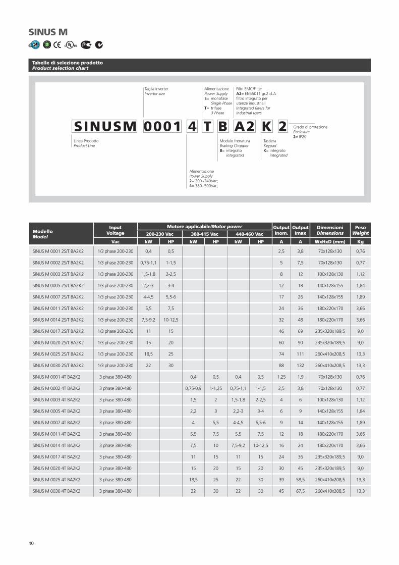
40
Tabelle di selezione prodottoProduct selection chart
SINUS M
Linea ProdottoProduct Line
Taglia inverterInverter size
AlimentazionePower SupplyS= monofase Single PhaseT= trifase 3 Phase
Modulo frenaturaBraking ChopperB= integrato integrated
TastieraKeypadK= integrato integrated
Filtri EMC/FilterA2= EN55011 gr.2 cl.Afi ltro integrato per utenze industrialiIntegrated fi lters for industrial users
SINUSM 0001 4 T B A2 K 2
AlimentazionePower Supply2= 200~240Vac;4= 380~500Vac;
Grado di protezioneEnclosure2= IP20
ModelloModel
InputVoltage
Motore applicabile/Motor power OutputInom.
OutputImax
DimensioniDimensions
PesoWeight200-230 Vac 380-415 Vac 440-460 Vac
Vac kW HP kW HP kW HP A A WxHxD (mm) Kg
SINUS M 0001 2S/T BA2K2 1/3 phase 200-230 0,4 0,5 2,5 3,8 70x128x130 0,76
SINUS M 0002 2S/T BA2K2 1/3 phase 200-230 0,75-1,1 1-1,5 5 7,5 70x128x130 0,77
SINUS M 0003 2S/T BA2K2 1/3 phase 200-230 1,5-1,8 2-2,5 8 12 100x128x130 1,12
SINUS M 0005 2S/T BA2K2 1/3 phase 200-230 2,2-3 3-4 12 18 140x128x155 1,84
SINUS M 0007 2S/T BA2K2 1/3 phase 200-230 4-4,5 5,5-6 17 26 140x128x155 1,89
SINUS M 0011 2S/T BA2K2 1/3 phase 200-230 5,5 7,5 24 36 180x220x170 3,66
SINUS M 0014 2S/T BA2K2 1/3 phase 200-230 7,5-9,2 10-12,5 32 48 180x220x170 3,66
SINUS M 0017 2S/T BA2K2 1/3 phase 200-230 11 15 46 69 235x320x189,5 9,0
SINUS M 0020 2S/T BA2K2 1/3 phase 200-230 15 20 60 90 235x320x189,5 9,0
SINUS M 0025 2S/T BA2K2 1/3 phase 200-230 18,5 25 74 111 260x410x208,5 13,3
SINUS M 0030 2S/T BA2K2 1/3 phase 200-230 22 30 88 132 260x410x208,5 13,3
SINUS M 0001 4T BA2K2 3 phase 380-480 0,4 0,5 0,4 0,5 1,25 1,9 70x128x130 0,76
SINUS M 0002 4T BA2K2 3 phase 380-480 0,75-0,9 1-1,25 0,75-1,1 1-1,5 2,5 3,8 70x128x130 0,77
SINUS M 0003 4T BA2K2 3 phase 380-480 1,5 2 1,5-1,8 2-2,5 4 6 100x128x130 1,12
SINUS M 0005 4T BA2K2 3 phase 380-480 2,2 3 2,2-3 3-4 6 9 140x128x155 1,84
SINUS M 0007 4T BA2K2 3 phase 380-480 4 5,5 4-4,5 5,5-6 9 14 140x128x155 1,89
SINUS M 0011 4T BA2K2 3 phase 380-480 5,5 7,5 5,5 7,5 12 18 180x220x170 3,66
SINUS M 0014 4T BA2K2 3 phase 380-480 7,5 10 7,5-9,2 10-12,5 16 24 180x220x170 3,66
SINUS M 0017 4T BA2K2 3 phase 380-480 11 15 11 15 24 36 235x320x189,5 9,0
SINUS M 0020 4T BA2K2 3 phase 380-480 15 20 15 20 30 45 235x320x189,5 9,0
SINUS M 0025 4T BA2K2 3 phase 380-480 18,5 25 22 30 39 58,5 260x410x208,5 13,3
SINUS M 0030 4T BA2K2 3 phase 380-480 22 30 22 30 45 67,5 260x410x208,5 13,3

41

42
SINUS K Software Lift
Software Lift a modulazione vet-toriale per ascensori
- Ampia gamma di tensioni d’alimentazione da 200Vca a 500Vca- Frequenza ingresso 50 - 60Hz- Potenze da 1,8 - 75 kW- Compatibile con software di teleassistenza, “REMOTE DRIVE”
via internet
Vector modulation Lift Software for lift applications
- Wide power supply voltage range, 200Vac - 500Vac- Input frequency 50 - 60Hz- Power range 1,8 - 75 kW- Full compatibility with teleservice software “REMOTE DRIVE”
on internet

43
SINUS K Software Lift
Caratteristiche tecnicheTechnical features
- Elevato comfort e posizionamento senza retroazione per im-piego con velocità a 1,2m/sec.
- Possibilità di utilizzare la retroazione di velocità per velocità fi no a 2,5m/sec.
- Frequenza di carrier fi no a 16kHz per un funzionamento silenzioso- Sovraccarico ammesso 150-175% per 120sec.- Modulo di frenatura compreso.- Display LCD su due righe, 32 caratteri, remotabile (Opzionale)- 3 velocità disponibili più una di manutenzione- Tester multifunzionale integrato- Storico allarmi- Protezione termica motore intergrata- Riavvia automatico in caso di anomalia- Curve a S con ampia possibilità di scelta dei valori di accelera-
zione e jerk- Regolazione della frequenza di uscita da 0 a 800 Hz- 8 ingressi digitali programmabili con regolazione di timer interni- 2 uscite confi gurabili a relè con contatti in scambio- 1 uscita open collector- Tensioni ausiliarie 24Vdc, 10Vdc- 2 uscite analogiche confi gurabili 0-10Vdc, 0(4)-20mA- Comunicazione seriale RS485 con protocollo MODBUS RTU- Conforme alla direttiva ascensori EN81- EMC conforme UNI EN 12015 con l’utilizzo di fi ltri integrati tipo
A1 per correnti inferiori a 25A e tipo A2 per correnti superiori
- High comfort and precise positioning without feedback for ap-plication with speed up to 1,2m/sec.
- Possibility to use speed feedback for lift with speed up to 2,5m/sec.
- Totally noiseless operation given by carrier frequency up to 16kHz
- Overload 150-175% for 120sec.- Included braking module.- 2 line LCD display, 32 digit, remotable (Optional)- 3 available speed plus one for maintenance- Integrated multimeter- Trip Log- Integrated thermal protection for motor- Automatic restart in case of inverter stop for alarm- S curve with large choice of acceleration values and jerk- Regulation of output frequency from 0 to 800 Hz- 8 programmable inputs with regulation of internal timers- 2 programmable relays outputs- 1 open collector output- Auxiliary 24Vdc, 10Vdc- 2 programmable analog ouputs 0-10Vdc, 0(4)-20mA- RS485 serial communication with MODBUS RTU protocol- EN 81 compliant to lift directive- EMC conform UNI EN 12015 with integrated fi lters A1 for cur-
rent below 25A and A2 fi lters for current above 25A
Opzioni- Modulo emergenza BU850- Software “Remote Drive”- Resistenze di frenatura- Filtri toroidali d’uscita- Induttanze ingresso e uscita- Convertitore RS232/485- Kit remotizzazione tastiera (5 metri)- Kit potenziometro- Kit montaggio passante- Scheda encoder- Convertitore MODBUS/Profi bus DP-CanBus-Device Net ecc.
Options- Emergency module BU850- “Remote Drive” software- Braking resistors- Output fi lters- Input and output chokes- RS232/485 converter- Kit remote keyboard operation (5 metres)- Kit potentiometer- Kit for heatsink segregation- Encoder card- Converter for MODBUS/Profi bus DP-CanBus-Device Net etc.
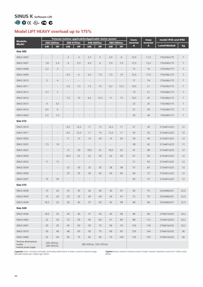
44
ModelloModel
Potenza motore applicabile/Applicable motor power Inom.inverter
A
Imax inverter
A
model IP20 and IP00200-240Vac 380-415Vac 440-460Vac 480-500Vac
LxAxP/WxHxD kgkW HP kW HP kW HP kW HP
Size S05
SINUS 0005 - - 3 4 3,7 5 4,5 6 10,5 11,5 170x340x175 7
SINUS 0007 1,8 2,5 4 5,5 4,5 6 5,5 7,5 12,5 13,5 170x340x175 7
SINUS 0008 2,2 3 - - - - - - 15 16 170x340x175 7
SINUS 0009 - - 4,5 6 5,5 7,5 7,5 10 16,5 17,5 170x340x175 7
SINUS 0010 3 4 - - - - - - 17 19 170x340x175 7
SINUS 0011 - - 5,5 7,5 7,5 10 9,2 12,5 16,5 21 170x340x175 7
SINUS 0013 3,7 5 - - - - - - 19 21 170x340x175 7
SINUS 0014 - - 7,5 10 9,2 12,5 11 15 16,5 25 170x340x175 7
SINUS 0015 4 5,5 - - - - - - 23 25 170x340x175 7
SINUS 0016 4,5 6 - - - - - - 27 30 170x340x175 7
SINUS 0020 5,5 7,5 - - - - - - 30 36 170x340x175 7
Size S12
SINUS 0016 - - 9,2 12,5 11 15 12,5 17 27 30 215x401x225 12
SINUS 0017 - - 9,2 12,5 11 15 12,5 17 30 32 215x401x225 12
SINUS 0020 - - 11 15 15 20 15 20 30 36 215x401x225 12
SINUS 0023 7,5 10 - - - - - - 38 42 215x401x225 11
SINUS 0025 - - 15 20 18,5 25 18,5 25 41 48 215x401x225 12
SINUS 0030 - - 18,5 25 22 30 22 30 41 56 215x401x225 12
SINUS 0033 11 15 - - - - - - 51 56 215x401x225 12
SINUS 0034 - - 22 30 25 35 28 38 57 63 215x401x225 12
SINUS 0036 - - 25 35 30 40 30 40 60 72 215x401x225 12
SINUS 0037 15 20 - - - - - - 65 72 215x401x225 12
Size S15
SINUS 0038 15 20 25 35 30 40 30 47 65 75 225x466x331 22,5
SINUS 0040 15 20 25 35 30 40 34 47 72 75 225x466x331 22,5
SINUS 0049 18,5 25 30 40 37 50 43 58 80 96 225x466x331 22,5
Size S20
SINUS 0049 18,5 25 30 40 37 50 43 58 80 96 279x610x332 33,2
SINUS 0060 22 30 37 50 45 60 51 69 88 112 279x610x332 33,2
SINUS 0067 25 35 45 60 50 70 56 76 103 118 279x610x332 33,2
SINUS 0074 30 40 48 65 55 75 69 93 120 144 279x610x332 36
SINUS 0086 32 45 55 75 65 90 74 100 135 155 279x610x332 36
Tensione alimentazione inverterInverter power supply
200-240Vac; 280-360Vdc
380-500Vac; 530-705Vdc
Legenda Inom= corrente nominale continuativa dell’inverter • Imax= corrente massima eroga-bile dall’inverter per 120sec ogni 20min
Caption Inom= inverter nominal current • Imax= inverter maximum current for 120sec every 20min
SINUS K Software Lift
Model LIFT HEAVY overload up to 175%

45

46
ASAC0/ASAC1 Soft starter
Avviatori statici soft-start/stop per motori asincroni trifase
- Gamma 7,5kW a 110kW- Tensioni d’alimentazione 200 - 575Vca- Contattore di By-pass integrato- Frequenza 50 - 60Hz- Compatibile con software di teleassistenza, “REMOTE DRIVE”
via internet
Soft start/stop static starters forthree-phase asynchronous motors
- Range 7,5kW - 110kW- Power supply voltage range 200 - 575Vac- Internal By-pass Contactor- Input frequency 50 - 60Hz- Full compatibility with teleservice software “REMOTE DRIVE”
on internet

47
ASAC0/ASAC1 Soft starter
Caratteristiche tecnicheTechnical features
ASAC0 è la risposta giusta per chi deve salvare spazio e conte-nere i costi. Oltre alle caratteristiche di ASAC0, l’ASAC1 garan-tisce un’affi dabile protezione motore e controllo di corrente.
- Dimensioni compatte- By-pass integrato- Max sovraccarico ammesso 400% della corrente nominale- Grado di protezione IP20 (<=ASAC 55kW)- 3 Regolazioni: Tensione iniziale di partenza, Rampa di partenza e Rampa di fermata- 6 Segnalazioni: Mancanza alimentazione controllo, Soft starter Pronto, Anomalia Soft starter, Motore fermo, Motore
in Marcia, Motore in partenza/fermata- 3 Allarmi: Sezione di potenza, Frequenza d’alimentazione,- Comunicazione Seriale- 2 Ingressi digitali: Start, Stop- 1 Uscita relè: Comando contattore di linea- Pulsante di reset- Alimentazione controllo: 110-240Vac e 380-440Vac- Alimentazione Potenza: 200-440Vac ±10% / 200-575Vac ±10%- Frequenza d’ingresso: 50-60Hz ±10%
ASAC0 is the right solution to save space and keep costs under control. Besides the features of ASAC0, the ASAC1 grants a reliable motor protection and current control.
- Compact dimensions- Internal By-pass contactor- 400% max allowed overload of the nominal current- IP20 Enclosure (<=ASAC 55kW)- 3 Adjustments: Initial start voltage, Start ramp time, Soft stop
ramp time- 6 Indications: No control power, Starter Ready, Starter tripped,
Motor not running, Motor running at full speed, Motor star-ting/stopping
- 3 Alarms: Power circuit, Supply frequency,- Communication- 2 digital inputs: Start, Stop- 1 Output relay: Main contactor relay- Local reset- Control power supply: 110-240Vac and 380-440Vac- Power supply: 200-440Vac ±10% / 200-575Vac ±10%- Input frequency: 50-60Hz ±10%
Caratteristiche tecniche addizionali ASAC 1ASAC 1 additional technical features
- 8 Regolazioni: Corrente nominale motore, Rampa di corrente, Limite di corrente, Termica motore, Rampa di fermata, Tempo di partenza eccessivo, Protezione Senso ciclico, Funzione relè ausiliario
- Ulteriori 5 allarmi: Tempo di partenza eccessivo, Sovraccarico motore, Sovratemperatura motore, Sbilanciamento di fase, Senso ciclico
- Ulteriore Ingresso digitale: Sonda termica motore- Ulteriore uscita a relè: Relè programmabile
- 8 adjustments: Motor FLC, Current Ramp, Current Limit, Mo-tor Trip Class, Soft Stop Time, Excess Start Time, Phase Se-quence Protection, Auxiliary Relay Function
- 5 additional Alarms: Excess start time, Motor overload, Motor thermistor, Phase imbalance, Phase sequence
- 1 additional Digital input: Motor thermistor probe- 1 additional Output relay: Programmable relay
Opzioni (ASAC 0/ASAC 1)- Tensione alimentazione controllo a 24Vac/Vdc- Fusibili extra-rapidi- Porta seriale RS485 con protocollo MODBUS RTU, DeviceNet,
Profi bus, ASI- Pannello di controllo remoto (duplicatore RS485, 1 uscita
4-20mA)- Convertitore RS232/485
Options (ASAC 0/ASAC 1)- 24Vac/Vdc Control Power Supply- Extra-fast fuses- RS485 Serial communication port with MODBUS RTU DeviceNet, Profi bus, ASI protocol- Remote control panel (RS485 doubler, one 4-20mA output)- RS232/485 converter

48
Tabelle di selezione prodottoProduct selection chart
ASAC0/ASAC1 Soft starter
ASAC 1 / 007 / 4 / 1
Alimentazione di ControlloControl Supply1 = 110-240Vac & 380-440Vac2 = 24Vac/Vdc
Alimentazione di ReteMain Supply4 = 3Ø, 200-440Vac, 45-66Hz5 = 3Ø, 200-575Vac, 45-66Hz
Modelli/Models
Versione/Version:0 = Basic1 = Advanced
Modello Model
Potenza motore applicabile/Applicable motor powerFLC* Dimensioni (LxAxP)
Dimensions (WxHxD)Peso
Weight200-240Vac 380-415Vac 440Vac 460-500Vac 575Vac
kW kW kW kW kW A mm Kg
ASAC0/ASAC1 007 4,5 9,2 9,2 11 11 18 98x203x163 2,1
ASAC0/ASAC1 015 9,2 15 18,5 18,5 22 34 98x203x163 2,1
ASAC0/ASAC1 018 11 18,5 22 22 30 42 98x203x163 2,1
ASAC0/ASAC1 022 11 22 30 30 37 48 98x203x163 2,1
ASAC0/ASAC1 030 15 30 37 37 45 60 98x203x163 2,1
ASAC0/ASAC1 037 22 37 45 45 55 75 145x215x191 4,3
ASAC0/ASAC1 045 22 45 55 55 55 85 145x215x191 4,3
ASAC0/ASAC1 055 30 55 55 55 75 100 145x215x191 4,3
ASAC0/ASAC1 075 45 75 75 90 110 140 202x240x212 6,8
ASAC0/ASAC1 090 55 90 90 110 132 170 202x240x212 6,8
ASAC0/ASAC1 110 55 110 110 132 160 200 202x240x212 6,8
Tensione alimentazione Soft-StarterSoft-Starter power supply
200-240Vac 200-575Vac
* FLC=Corrente nominale a pieno carico/Full load current.

49

50
ASAB Soft starter
Avviatori statici soft-start/stop per motori asincroni trifase
I soft starter ASAB utilizzano quanto di più avanzato offre la tecnologia per l’avviamento statico di motori di potenza com-presa tra 7 kW e 800 kW. I soft starter ASAB soddisfano ogni esigenza di protezione del motore e dell’impianto e garantisco-no affi dabilità e prestazioni elevate anche nelle applicazioni più complesse.
Soft start/stop static starters forthree-phase asynchronous motors
The ASAB is an advanced digital soft start solution for motors from 7 kW to 800 kW. ASAB soft starters provide a complete range of motor and system protection features and have been designed for reliable performance in the most demanding instal-lation situations

51
ASAB Soft starter
Caratteristiche tecnicheTechnical features
Vasta gamma di opzioni di avviamento/arresto- AAC (Adaptive Acceleration Control – Controllo adattativo
dell’accelerazione)- A corrente costante- A rampa di corrente- Soft stop di tipo TVR (Timed Voltage Ramp)- Frenatura
Modelli per tutti i tipi di connessione- 23 A ÷ 1600 A (nominale)- 200 VAC ÷ 525 VAC- 380 VAC ÷ 690 VAC- By-pass interno fi no a 220 A- Connessione a 3 fi li o a 6 fi li (rilevazione automatica)
Ingressi e uscite- Ingressi di controllo remoto (3 ingressi fi ssi, 1 programmabile)- Uscite a relè (3 uscite programmabili)- Uscita analogica- Protocolli di comunicazione ModDeviceNet, Modbus o Profi bus (opzione)
Display di facile lettura- Display multilingua- Visualizzazione degli stati di funzionamento e grafi cazione del rendimento Storico eventi con indicazione di data e ora- Funzione contatore (numero di avviamenti, ore di marcia, kWh)- Monitoraggio del rendimento (corrente, tensione, fattore di potenza, kWh)- Misure grafi cabili in maniera personalizzata
Protezioni personalizzabili- Sovraccarico motore- Tempo di avviamento eccessivo- Soglia di minima corrente- Sovracorrente istantanea- Squilibrio di corrente- Frequenza di rete- Allarme esterno- Termistore motore- Circuito di potenza- Senso ciclico
Extensive starting and stopping options- AAC Adaptive Acceleration Control- Constant current- Current ramp- Timed voltage ramp soft stop- Brake
Models for all connection requirements- 23 A to 1600 A (nominal)- 200 VAC to 525 VAC- 380 VAC to 690 VAC- Internally bypassed up to 220 A- In-line or inside delta connection (auto-detect)
Inputs and outputs- Remote control inputs (3 x fi xed, 1 x programmable)- Relay outputs (3 x programmable)- Analog output - DeviceNet, Modbus or Profi bus communication modules
(optional)
Easy-to-read display with comprehensive feedback- Multi-language feedback- Multiple status screens and performance graphs- Date and time stamped event logging- Operational counters (number of starts, hours run, kWh)- Performance monitoring (current, voltage, power factor, kWh)- User-programmable monitoring screen
Customisable protection- Motor overload- Excess start time- Undercurrent- Instantaneous overcurrent- Current imbalance- Mains frequency- Input trip- Motor thermistor- Power circuit- Phase sequence
(Pending)

52
6 wire connection
SeriesASAB
Rating - AmpsXXXX
Bypass/Non BypassB / C
Mains Voltage5 / 7
Control Voltage12 / 14
IP Rating2 / 0
XXXX Current in Amps e.g. 0023
Bypass/Non Bypass B = With Internal Bypass Contactor, C = Without Internal Bypass Contactor (Continuous)
Mains Voltage 5 = 200V AC ~ 440 V AC, 7 = 380 V AC ~ 690 V AC
Control Voltage 12 = 110V AC or 220 VAC, 14 = 24 V AC/DC,
IP Rating 2 = IP20, 0 = IP00
Caratteristiche tecnicheTechnical features
ASAB Soft starter
(Pending)
Es: Pompa sommersa con motore da 45kW, 4 poliEx: 45kW, 4 pole motor for bore pump
Tipo motorMotor type
Pn nN MN In a 400V cosfi Is
In
Ts
Tn
Tmax
Tn
PesoWeightkW GV RPM Nm (A) P.F. %
400/690 Vac
MA 225 M 4 45 60 1475 291,5 80 0,88 92,3 7,2 2,2 2,3 309
T1
Ts
Tn
x Mn
xIs
In=
98
2,2x291,5x 7,2 = 2,8
TL - Coppia massima di spunto richiesta dal carico/Maximum starting torque requested by load= 98NmIST - Sovraccarico di corrente rispetto alla nominale/Overload value
η

53
Scelta Del SovraccaricoOverload Choice
Settori d’impiegoApplications
Sovraccarico/Overload (IST)
3 3,5 4 4,5
AgitatoreAgitator •
AtomizzatoreAtomizer •
Lava bottiglieBottle washer •
CentrifugaCentrifuge •
SminuzzatoreChipper •
Compressore centrifugoCentrifugal compressor •
Compressore a pistoni a caricoLoaded piston compressor •
Compressore a pistoni a vuotoUnloaded piston compressor •
Compressore a vite a caricoScrew Compressor loaded •
Compressore a vite a vuotoScrew Compressor unloaded •
Nastro di trasportoConveyor belt •
RullieraConveyor roller •
CocleaConveyor screw •
Frantumatore a conoCrusher cone •
Frantumatore a mascellaCrusher jaw •
Frantumatore rotativoCrusher rotary •
Frantumatore ad impatto verticaleCrusher vertical impact •
ScortecciatoreDebarker •
EssiccatoreDryer •
AspiratoreDust collector •
TaglierinaEdger •
Ventilatore assiale con smorzatoreDamped axial fan •
Ventilatore assiale non smorzatoreUndamped axial fan •
Ventilatore centrifugocon smorzatoreCentrifugal damped fan
•
Settori d’impiegoApplications
Sovraccarico/Overload (IST)
3 3,5 4 4,5
Ventilatore centrifugo non smorzatoUndamped centrifugal fan •
Ventilatore ad alta pressioneFan high pressure •
MolaGrinder •
Centralina idraulicaHydraulic power pack •
MulinoMill •
Mulino a sfereBall Mill •
Mulino a martelliHammer Mill •
Mulino rotativiRoller Mill •
MiscelatoreMixer •
PallettizzatorePalletiser •
PiallatriciPlaners •
PressaPress •
Pompe sommerseBore pumps •
Pompe centrifugheCentrifugal pumps •
Pompe a sfasamento positivoPositive displacement pumps •
Pompe fanghiSlurry pumps •
SpappolatorePulper •
Tavolo rotativoRotary table •
LevigatriceSander •
Sega a nastroBandsaw •
Sega circolareCircular saw •
SeparatoreSeparator •
TrinciatriceShredder •
AffettatriceSlicer •
BottaleTumbler •
ASAB Soft starter
(Pending)
Queste tabelle sono da ritenersi indicative. La reale corrente di spunto richesta è una carattestica intrinseca del motore e della macchina. Per dimensionamenti precisi vedere l’esempio.
The above tables are intended as a guide only. Individual machine and motor characte-ristics will determine the actual start current requirements. For accurate designing see the example.

54
ASAB Soft starter
(Pending)
ModelloModel200-525V
Size
Start per
Hour
300%, 10s350%, 15s 400%, 20s
450%, 30s Start per
Hour
300%, 10s350%, 15s 400%, 20s
450%, 30s
Light Dty Hvy Dty Light Dty Hvy Dty
N° Amps Amps Amps Amps N° Amps Amps Amps Amps
Bypassed ratings In-line connection Bypassed ratings Inside delta connection
ASAB-0023B/5/12/2 G1 no fan 10 23 20 17 15 10 35 30 26 22
ASAB-0043B/5/12/2 G1 no fan 10 43 37 31 26 10 65 59 51 44
ASAB-0053B/5/12/2 G1 no fan 10 53 53 46 37 10 80 80 69 55
ASAB-0076B/5/12/2 G1 no fan 6 76 64 55 47 6 114 96 83 70
ASAB-0097B/5/12/2 G1 6 97 82 69 58 6 146 123 104 87
SAB-0100B/5/12/2 G1 6 100 88 74 61 6 150 132 112 92
ASAB-0105B/5/12/2 G1 6 105 105 95 78 6 158 158 143 117
ASAB-0145B/5/12/0 G2 6 145 123 106 90 6 218 184 159 136
ASAB-0170B/5/12/0 G2 6 170 145 121 97 6 255 217 181 146
ASAB-0200B/5/12/0 G2 6 200 189 160 134 6 300 283 241 200
ASAB-0220B/5/12/0 G2 6 220 210 178 148 6 330 315 268 223
Non Bypassed ratings In-line connection Bypassed ratings Inside delta connection
ASAB-0255C/5/12/0 G3 6 255 231 201 176 6 383 346 302 264
ASAB-0380C/5/12/0 G4 6 380 380 359 299 6 570 570 539 449
ASAB-0430C/5/12/0 G4 6 430 430 368 309 6 645 645 552 464
ASAB-0620C/5/12/0 G4 6 620 620 540 434 6 930 930 810 651
ASAB-0650C/5/12/0 G4 6 650 650 561 455 6 975 975 842 683
ASAB-0790C/5/12/0 G4 6 790 790 714 579 6 1185 1185 1071 868
ASAB-0930C/5/12/0 G4 6 930 930 829 661 6 1395 1395 1244 992
ASAB-1200C/5/12/0 G5 6 1200 1200 1200 1071 6 1800 1800 1800 1606
ASAB-1410C/5/12/0 G5 6 1410 1410 1319 1114 6 2115 2115 1979 1671
ASAB-1600C/5/12/0 G5 6 1600 1600 1600 1353 6 2400 2400 2400 2030
Dimensioni e peso - Complete Class E2 Soft StarterDimensions and weight - Complete Class E2 Soft Starter
Modelli/Models Dimensioni LxAxP/Dimensions WxHxD (mm) Peso/Weight (Kg)
ASAB-0023B 156,4x294,6x192,2 3,2
ASAB-0043B 156,4x294,6x192,2 3,2
ASAB-0053B 156,4x294,6x192,2 3,2
ASAB-0076B 156,4x294,6x222,7 3,5
ASAB-0097B 156,4x294,6x222,7 4,8
ASAB-0100B 156,4x294,6x222,7 4,8
ASAB-0105B 156,4x294,6x222,7 4,8
ASAB-0145B 282x438x250 16
ASAB-0170B 282x438x250 16
ASAB-0200B 282x438x250 16
ASAB-0220B 282x438x250 16

55
ModelloModel380-690V
Size
Start per
Hour
300%, 10s350%, 15s 400%, 20s
450%, 30s Start per
Hour
300%, 10s350%, 15s 400%, 20s
450%, 30s
Light Dty Hvy Dty Light Dty Hvy Dty
N° Amps Amps Amps Amps N° Amps Amps Amps Amps
Bypassed ratings In-line connection Bypassed ratings Inside delta connection
ASAB-0023B/7/12/2 G1 no fan 10 23 20 17 15 10 35 30 26 22
ASAB-0043B/7/12/2 G1 no fan 10 43 37 31 26 10 65 59 51 44
ASAB-0053B/7/12/2 G1 no fan 10 53 53 46 37 10 80 80 69 55
ASAB-0076B/7/12/2 G1 no fan 6 76 64 55 47 6 114 96 83 70
ASAB-0097B/7/12/2 G1 6 97 82 69 58 6 146 123 104 87
ASAB-0100B/7/12/2 G1 6 100 88 74 61 6 150 132 112 92
ASAB-0105B/7/12/2 G1 6 105 105 95 78 6 158 158 143 117
ASAB-0145B/7/12/0 G2 6 145 123 106 90 6 218 184 159 136
ASAB-0170B/7/12/0 G2 6 170 145 121 97 6 255 217 181 146
ASAB-0200B/7/12/0 G2 6 200 189 160 134 6 300 283 241 200
ASAB-0220B/7/12/0 G2 6 220 210 178 148 6 330 315 268 223
Non Bypassed ratings In-line connection Bypassed ratings Inside delta connection
ASAB-0255C/7/12/0 G3 6 255 231 201 176 6 383 346 302 264
ASAB-0380C/7/12/0 G4 6 380 380 359 299 6 570 570 539 449
ASAB-0430C/7/12/0 G4 6 430 430 368 309 6 645 645 552 464
ASAB-0620C/7/12/0 G4 6 620 620 540 434 6 930 930 810 651
ASAB-0650C/7/12/0 G4 6 650 650 561 455 6 975 975 842 683
ASAB-0790C/7/12/0 G4 6 790 790 714 579 6 1185 1185 1071 868
ASAB-0930C/7/12/0 G4 6 930 930 829 661 6 1395 1395 1244 992
ASAB-1200C/7/12/0 G5 6 1200 1200 1200 1071 6 1800 1800 1800 1606
ASAB-1410C/7/12/0 G5 6 1410 1410 1319 1114 6 2115 2115 1979 1671
ASAB-1600C/7/12/0 G5 6 1600 1600 1600 1353 6 2400 2400 2400 2030
ASAB Soft starter
(Pending)
Dimensioni e peso - Complete Class E2 Soft StarterDimensions and weight - Complete Class E2 Soft Starter
Modelli/Models Dimensioni LxAxP/Dimensions WxHxD (mm) Peso/Weight (Kg)
ASAB-0255C 390x417x281 25
ASAB-0380C 430x545x299 50,5
ASAB-0430C 430x545x299 50,5
ASAB-0620C 430x545x299 53,5
ASAB-0650C 430x545x299 53,5
ASAB-0790C 430x545x299 53,5
ASAB-0930C 430x545x299 53,5
ASAB-1200C 574x750x361 140
ASAB-1410C 574x750x361 140
ASAB-1600C 574x750x361 140
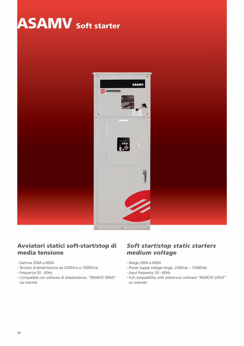
56
ASAMV Soft starter
Avviatori statici soft-start/stop di media tensione
- Gamma 200A a 600A- Tensioni d’alimentazione da 2300Vca a 15000Vca- Frequenza 50 - 60Hz- Compatibile con software di teleassistenza, “REMOTE DRIVE”
via internet
Soft start/stop static starters medium voltage
- Range 200A a 600A- Power supply voltage range, 2300Vac - 15000Vac- Input frequency 50 - 60Hz- Full compatibility with teleservice software “REMOTE DRIVE”
on internet

57
ASAMV Soft starter
Caratteristiche tecnicheTechnical features
- Alimentazione da 2300Vac a 15000Vac, corrente nominale da 200 a 600A
- 3 tipi di avviamento (Corrente costante, rampa di corrente, controllo di coppia)
- Arresto (fermata in fl le, soft stop, fermata pompe, fermata automatica)
- Sovraccarico ammesso al 600% della corrente nominale- Grado di protezione IP54 versione in CABINET EMC classe A- Temperatura di esercizio 0÷+50°C (opzione -20÷+50°C)- Umidità relativa dal 5% al 95%- Grado d’inquinamento 3- Protezioni: sovra e sotto tensione, frequenza di alimentazione
fuori tolleranza, sequenza fasi errata, cortocircuito SCR, so-vraccarico motore (modello con termico) sovracorrente istan-tanea, sottocorrente, correnti sbilanciate, eccessivi tempo di avviamento, allarme circuito di potenza, allarme ausiliari.
- Interfaccia: 5 ingressi digitali (3 fi ssi, 2 programmabili), 8 usci-tè a relè (3 programmabili), 2 uscita analogica (programmabi-le), seriale RS485 Modbus-RTU
- Interfaccia operatore: Display LCD 2 linee 20 caratteri, pulsanti di Start-Stop-Reset-Locale/Remoto, led di segnalazione, storico allarmi (ultimi 60 allarmi con data e ora), contatore (numero avviamenti, ore di funzionamento, kWh), misure (corrente, tensione, fattore di potenza, kWh), programmazione delle mi-sure visualizzabili, Multi-level password di protezione
- Power supply from 2300Vac to 15000Vac, rated current from 200 to 600A
- 3 types of motor starting (Constant Current, Current Ramp, Torque Control)
- Stopping (Coast to stop, Soft Stop, Pump control profi les, Auto Stop)
- Allowed overload to 600% of the nominal current- CABINET MODEL IP54 protection degree Class A EMC- Operating temperature 0÷+50°C (option -20÷+50°C)- Humidity from 5% to 95%- Pollution degree 3- Protection: Under/ Overvoltage, Supply Frequency, Phase Se-
quence, Shorted SCR, Motor Overload (Thermal Model), In-stantaneous Overcurrent, Undercurrent, Current Imbalance, Excess Start Time, Power Circuit, Auxiliary Trip
- Interface: 5 Remote Control Inputs (3 x fi xed, 2 x program-mable), 6 Relay Outputs (3 fi xed, 3 x programmable), Ana-log Output (1 x programmable), Serial Output (1 x RS485 Modbus-RTU)
- Human Interface: LCD Display 20 characters 2 line, Start-Stop-Reset-Local/Remote keys, Starter Status LEDs, Event Log (99 positions, date and time stamped), Trip Log (60 positions, date and time stamped), Counters (starts, hours-run, kWh), Mete-ring (current, voltage, power factor, kWh), User Programma-ble Metering Screen, Multi-Level Password Protection
Tabelle di selezione prodottoProduct selection chart
ASAMV CABINET 0200 06 E2
Supply Voltage02 = 2300 VAC 50/60 Hz03 = 3300 VAC 50/60 Hz04 = 4160 VAC 50/60 Hz07 = 6600-7200 VAC 50/60 Hz15 = 11000-15000 VAC 50/60 Hz
E1 = IP54 Enclosure, and by-pass, Contactor
E2 = IP54 Enclosure, Switch-gear, Fuses, Line contactor, By-pass contactor
Current Rating200 = 500% 60 sec, 600% 30 sec300 = 500% 60 sec, 600% 30 sec400 = 500% 60 sec, 600% 30 sec600 = 500% 60 sec, 600% 30 sec
Opzioni- Interfaccia per sensori di temperatura esterna- Interfaccia Pt100- Interfaccia Profi bus- Interfaccia DeviceNet- Controllo per motori sincroni- PC Software Remote Drive- Tastiera remota- Trasformatore alimentazione unità di controllo- Protezione corto circuito verso terra
Options- RTD Interface- Interface Pt100- Profi bus Interface- DeviceNet Interface- Synchronous Motor Control- PC Software Remote Drive- Remote Operator- Control supply transformer- Ground fault protection

58
ASAMV Soft starter
Range di corrente - Basic Class E1 Soft StarterCurrent ratings - Basic Class E1 Soft Starter
Model ASAMV-CABINET Rated. Amps
Motor
HP kW
Volts 2300
200-02-E1200-02-E1 200200 800800 500500
400-02-E1400-02-E1 400400 15001500 10001000
600-02-E1600-02-E1 600600 25002500 19001900
Volts 3300
200-03-E1200-03-E1 200200 10001000 600600
400-03-E1400-03-E1 400400 18001800 12001200
600-03-E1600-03-E1 600600 30003000 22002200
Volts 4160
200-04-E1200-04-E1 200200 12501250 10001000
400-04-E1400-04-E1 400400 25002500 20002000
600-04-E1600-04-E1 600600 50005000 37503750
Volts 6000/7200*
200-07-E1200-07-E1 200200 25002500 20002000
400-07-E1400-07-E1 400400 50005000 37503750
600-07-E1600-07-E1 600600 75007500 56005600
Volts 11-15 kV
300-15-E1300-15-E1 300300 75007500 57005700
600-15-E1600-15-E1 600600 1500015000 1100011000
Dimensioni e peso - Basic Class E1 Soft StarterDimensions and weight - Basic Class E1 Soft Starter
Model ASAMV-CABINETIP54
H W P
200-02-E1 2337 914 762
400-02-E1 2337 914 762
600-02-E1 2337 914 762
200-03-E1 2337 914 762
400-03-E1 2337 914 762
600-03-E1 2337 914 762
200-04-E1 2337 914 762
400-04-E1 2337 914 762
600-04-E1 2337 914 762
200-07-E1 2337 914 762
400-07-E1 2337 914 762
600-07-E1* 2337 1829 762
300-15-E1 Contact factory Contact factory Contact factory
600-15-E1 Contact factory Contact factory Contact factory
*Potere riferente a 7200 V. per 6 kV considerare Rated current /*Power calculated for 7200 Volt. for 6000 Volt use the Rated Amps
*Modello in revisione/New model under development.

59
*Potere riferente a 7200 V. per 6 kV considerare Rated current /*Power calculated for 7200 Volt. for 6000 Volt use the Rated Amps
ASAMV Soft starter
Range di corrente - Basic Class E2 Soft StarterCurrent ratings - Basic Class E2 Soft Starter
Model ASAMV-CABINET Rated. Amps
Motor
HP kW
Volts 2300
200-02-E1200-02-E1 200200 800800 500500
400-02-E1400-02-E1 400400 15001500 10001000
600-02-E1600-02-E1 600600 25002500 19001900
Volts 3300
200-03-E1200-03-E1 200200 10001000 600600
400-03-E1400-03-E1 400400 18001800 12001200
600-03-E1600-03-E1 600600 30003000 22002200
Volts 4160
200-04-E1200-04-E1 200200 12501250 10001000
400-04-E1400-04-E1 400400 25002500 20002000
600-04-E1600-04-E1 600600 50005000 37503750
Volts 6000/7200*
200-07-E1200-07-E1 200200 25002500 20002000
400-07-E1400-07-E1 400400 50005000 37503750
600-07-E1600-07-E1 600600 75007500 56005600
Volts 11-15 kV
300-15-E1300-15-E1 300300 75007500 57005700
600-15-E1600-15-E1 600600 1500015000 1100011000
Dimensioni e peso - Complete Class E2 Soft StarterDimensions and weight - Complete Class E2 Soft Starter
Model ASAMV-CABINETIP54
H W P
200-02-E2 2337 914 762
400-02-E2 2337 914 762
600-02-E2 2337 1829 762
200-03-E2 2337 914 762
400-03-E2 2337 914 762
600-03-E2 2337 1829 762
200-04-E2 2337 914 762
400-04-E2 2337 914 762
600-04-E2 2337 1829 762
200-07-E2 2337 1829 762
400-07-E2 2337 1829 762
600-07-E2* 2337 1829 762
300-15-E2 Contact factory Contact factory Contact factory
600-15-E2 Contact factory Contact factory Contact factory
*Modello in revisione/New model under development.

60
DCREG2-DCREG4
Convertitori digitali CA/CC, DCREG2 monodirezionale, DCREG4 bidirezionale
- Gamma di potenza da 10A a 4500A (2,4 kW - 3200kW)- Ampia gamma di tensioni d’alimentazione da 200Vca a
690Vca (1000 Vca)- Frequenza 50 - 60Hz- Full digital- Compatibile con software di teleassistenza, “REMOTE DRIVE”
via internet
AC/DC digital converters, two quadrant DCREG2, four quadrant DCREG4
- Power range 10A - 4500A (2,4kW - 3200kW)- Wide power supply voltage range, 200Vac - 690Vac (1000 Vac)- Input frequency 50 - 60Hz- Full digital- Full compatibility with teleservice software “REMOTE DRIVE”
on internet

61
DCREG2-DCREG4
Caratteristiche tecnicheTechnical features
- Autotaratura di corrente e velocità (Riduce possibilità di errori e i tempi di installazione)
- Autotaratura di campo (Riduce possibilità di errori e i tempi di installazione)
- Defl ussatore integrato (per funzionamento a coppia o poten-za costante)
- Economy (riduce la corrente di campo quando il motore è fermo)
- Boost di campo (aumenta la coppia del motore alla partenza)- Controllo predittivo (aumenta la risposta dinamica del motore)- Tester multifunzione integrato- Multirampe di velocità- Rampe a “S”- Doppio anello di velocità con adattamento automatico- Retroazione da armatura da dinamo tachimetrica e da encoder- Commutazione automatica della retroazione in armatura in
caso di rottura dinamo/encoder (maggiore sicurezza di funzionamento motore)
- Controllo del limite di corrente a gradino o iperbolico- 7 livelli di velocità- Comandi di JOG- Autoreset allarmi (continuità di funzionamento)- Potenziometro digitale integrato- Timer su uscite digitali- Controllo locale da tastiera- Insensibilità senso ciclico (semplifi ca il collegamento all’impianto)- Alimentazioni indipendenti tra controllo e potenza- 8 ingressi digitali programmabili- 4 ingressi analogici programmabili 0-±10Vdc, 0(4)-20mA- Doppio ingresso encoder- Ingresso dinamo tachimetrica- 5 uscite confi gurabili a relè- Tensioni ausiliarie 24Vdc, ±10Vdc, 5Vdc- 1 uscita analogica di velocita ±10Vdc- 1 uscita analogica di corrente ±10Vdc- 2 uscite analogiche confi gurabili 0-±10Vdc, 0(4)-20mA- Conforme alla norma EMC EN61800-3 ed. 2
- Self-calibration of current and speed (Reduce possibility of er-ror and installation time)
- Self-calibration of fi eld (Reduces possibility of error and installation time)- Internal fi eld converter (for operation in constant torque or
power)- Field economy (reduce the fi eld current when motor is
stopped)- Field boost (increase torque on motor start)- Predictive control (increase the dynamic response of the
motor)- Integrated multimeter- Speed multiramps- “S” ramps- Double speed ring with automatic adaptation- Feedback from tachometric dynamo, from encoder and armature- Automatic switching of the feedback in armature in the event
of breakdown of dynamo/encoder (higher safety operation)- Control of the current limit in steps or hyperbolic- 7 levels of speed- JOG commands- Auto-reset alarms- Integrated digital potentiometer- Timer on digital outputs- Local control from keyboard- Insensitivity to phase-rotation ( for easy connection)- Independent supplies to control and power- 8 programmable inputs- 4 programmable analog inputs 0-±10Vdc, 0(4)-20mA- Double encoder input- Tacho input- 5 programmable relay outputs- Auxiliary 24Vdc, ±10Vdc, 5 Vdc- 1 analog speed output ±10Vdc- 1 analog current output ±10Vdc- 2 programmable analog ouputs 0-±10Vdc, 0(4)-20mA- EMC compliant with EN 61800-3 2nd ed.
Opzioni- Software “Remote Drive”- Tastiera di programmazione- Kit remotizzazione tastiera (5 metri)- Interfaccia RS232/485- MODBUS RTU 115,2kbps- Profi bus DP 12mbps - CanBus - Device Net ecc.- Kit protezione IP20- Induttanze di ingresso- Kit montaggio passante- Fusibili extra rapidi- Unità Clamping CU400 per elettromagneti
Options- “Remote Drive” software- Keyboard- Kit remote keyboard operation (5 metres)- RS232/485 interface- MODBUS RTU 115,2kbps- Profi bus DP 12mbps - CanBus - Device Net etc.- IP 20 kit protection degree- Input chokes- Kit for heatsink segregation- Fast fuses- CU400 Clamping unit for electromagnets

62
*Grandezza/Size 1
Range di correnteCurrent ratings 10 20 40 70
*Corrente nominale armatura*Armature rated current 10A 20A 40A 70A
SovraccaricoOverload 150% 150% 150% 150%
*Uscita tensione armatura*Armature output Voltage 600max (500 Vac input)
Corrente nominale campoField rated current 5A 5A 5A 5A
Uscita tensione campoField output voltage 425max (1500 Vac input)
Fusibili extrarapidi lato ACAC Fast fuses 35-40A 00T/80 35-40A 00T/80 35-40A 00T/80 63A 00T/80
Fusibili extrarapidi lato DCDC Fast fuses 35-40A 00T/80 35-40A 00T/80 50A 00T/80 100A 00T/80
*Dimensioni (LxPxH) mm*Dimensions (WxDxH) mm 214x264x440 214x264x440 214x264x440 214x264x440
*Pesi kg*Weight kg 13 13 13 14
*Grandezza/Size 1
Range di correnteCurrent ratings 100 150 180 250 350
*Corrente nominale armatura*Armature rated current 100A 150A 180A 250A 350A
SovraccaricoOverload 150% 150% 150% 150% 150%
*Uscita tensione armatura*Armature output Voltage 600max (500 Vac input)
Corrente nominale campoField rated current 5A 15A 15A 15A 15A
Uscita tensione campoField output voltage 425max (1500 Vac input)
Fusibili extrarapidi lato ACAC Fast fuses 100A 00T/80 160A 00T/80 200A 00T/80 250A 00T/80 315A 00T/80
Fusibili extrarapidi lato DCDC Fast fuses 125A 00T/80 200A 00T/80 250A 00T/80 315A 00T/80 375-400A 00T/80
*Dimensioni (LxPxH) mm*Dimensions (WxDxH) mm 214x264x440 214x264x440 214x264x440 214x264x440 214x264x440
*Pesi kg*Weight kg 15 15 15 18 18
*Grandezza/Size 2
Range di correnteCurrent ratings 410 500 600 900
*Corrente nominale armatura*Armature rated current 410A 500A 600A 900A
SovraccaricoOverload 150% 150% 150% 150%
*Uscita tensione armatura*Armature output Voltage 600max (500 Vac input)
Corrente nominale campoField rated current 35A 35A 35A 35A
Uscita tensione campoField output voltage 425max (1500 Vac input)
Fusibili extrarapidi lato ACAC Fast fuses 450A 2T/80 550A 2T/80 550A 2T/80 1000A 3T/80
Fusibili extrarapidi lato DCDC Fast fuses 550A 2T/80 700A 2T/80 700A 2T/80 1000A 3T/80
*Dimensioni (LxPxH) mm*Dimensions (WxDxH) mm 333x360x596 333x360x596 333x360x596 333x360x596
*Pesi kg*Weight kg 38 45 45 45
DCREG2
1) La serie DCREG è disponibile in differenti range di tensione d’alimentazione: 440Vca - 500Vca - 600Vca - 690Vca (fi no a 1000Vca su richiesta)
** Corrente nominale, dimensione e pesi possono cambiare in funzione della tensione di alimentazione** Nel DCREG MODULARE.S, alle dimesioni indicate va aggiunta l’unità di controllo
214x265x440 (LxPxA)
1) DCREG series is available in different range of power supply: 440Vac - 500Vac - 600Vac - 690Vac (on request up to 1000 Vac)
** Rated current, dimension and weight can be changed in function of the power power supply** DCREG MODULARE.S, at the shown dimensins must be added the control unit
214x265x440 (WxDxH)

63
*Grandezza/Size 2A
Range di correnteCurrent ratings 1200
*Corrente nominale armatura*Armature rated current 1200A
SovraccaricoOverload 150%
*Uscita tensione armatura*Armature output Voltage 600max (500 Vac input)
Corrente nominale campoField rated current 35A
Uscita tensione campoField output voltage 425max (1500 Vac input)
Fusibili extrarapidi lato ACAC Fast fuses 1250A 3T/80
Fusibili extrarapidi lato DCDC Fast fuses 1250A 3T/80
*Dimensioni (LxPxH) mm*Dimensions (WxDxH) mm 333x453x685
*Pesi kg*Weight kg 51
*Grandezza/Size MODULARE.S
Range di correnteCurrent ratings 1400S 1800S 2000S 2300S
*Corrente nominale armatura*Armature rated current 1400A 1800A 2000A 2300A
SovraccaricoOverload
125% (150% Overload in temperatura dissipatore <40°C125% (150% Overload with heatsink temperature <40°C
*Uscita tensione armatura*Armature output Voltage 520max (500 Vac input)
Corrente nominale campoField rated current 35A 35A 35A 35A
Uscita tensione campoField output voltage 425max (1500 Vac input)
Fusibili extrarapidi lato ACAC Fast fuses
Inclusi a bordoIncluded on board
Inclusi a bordoIncluded on board
Inclusi a bordoIncluded on board
Inclusi a bordoIncluded on board
Fusibili extrarapidi lato DCDC Fast fuses
Inclusi a bordoIncluded on board
Inclusi a bordoIncluded on board
Inclusi a bordoIncluded on board
Inclusi a bordoIncluded on board
*Dimensioni (LxPxH) mm*Dimensions (WxDxH) mm 500x275x860 (Size A)** 500x275x860 (Size A)** 500x275x860 (Size A)** 620x360x884 (Size B)**
*Pesi kg*Weight kg 79 79 79 124
*Grandezza/Size MODULARE.S
Range di correnteCurrent ratings 2500S 2700S 3000S 3500S 4500S
*Corrente nominale armatura*Armature rated current 2500A 2700A 3000A 3500A 4500A
SovraccaricoOverload
125% (150% Overload in temperatura dissipatore <40°C125% (150% Overload with heatsink temperature <40°C
*Uscita tensione armatura*Armature output Voltage 520max (500 Vac input)
Corrente nominale campoField rated current 35A 35A 35A 35A 35A
Uscita tensione campoField output voltage 425max (1500 Vac input)
Fusibili extrarapidi lato ACAC Fast fuses
Inclusi a bordoIncluded on board
Inclusi a bordoIncluded on board
Inclusi a bordoIncluded on board
Inclusi a bordoIncluded on board
Inclusi a bordoIncluded on board
Fusibili extrarapidi lato DCDC Fast fuses
Inclusi a bordoIncluded on board
Inclusi a bordoIncluded on board
Inclusi a bordoIncluded on board
Inclusi a bordoIncluded on board
Inclusi a bordoIncluded on board
*Dimensioni (LxPxH) mm*Dimensions (WxDxH) mm 620x360x884 (Size B)** 712x395x945 (Size C)** 712x395x945 (Size C)** 784x415x1110 (Size D)** 968x482x1250 (Size E)**
*Pesi kg*Weight kg 124 164 164 206 319
DCREG2
1) La serie DCREG è disponibile in differenti range di tensione d’alimentazione: 440Vca - 500Vca - 600Vca - 690Vca (fi no a 1000Vca su richiesta)
** Corrente nominale, dimensione e pesi possono cambiare in funzione della tensione di alimentazione** Nel DCREG MODULARE.S, alle dimesioni indicate va aggiunta l’unità di controllo
214x265x440 (LxPxA)
1) DCREG series is available in different range of power supply: 440Vac - 500Vac - 600Vac - 690Vac (on request up to 1000 Vac)
** Rated current, dimension and weight can be changed in function of the power power supply** DCREG MODULARE.S, at the shown dimensins must be added the control unit
214x265x440 (WxDxH)

64
DCREG4
1) La serie DCREG è disponibile in differenti range di tensione d’alimentazione: 440Vca - 500Vca - 600Vca - 690Vca (fi no a 1000Vca su richiesta)
** Corrente nominale, dimensione e pesi possono cambiare in funzione della tensione di alimentazione** Nel DCREG MODULARE.S, alle dimesioni indicate va aggiunta l’unità di controllo
214x265x440 (LxPxA)
1) DCREG series is available in different range of power supply: 440Vac - 500Vac - 600Vac - 690Vac (on request up to 1000 Vac)
** Rated current, dimension and weight can be changed in function of the power power supply** DCREG MODULARE.S, at the shown dimensins must be added the control unit
214x265x440 (WxDxH)
*Grandezza/Size 1
Range di correnteCurrent ratings 10 20 40 70
*Corrente nominale armatura*Armature rated current 10A 20A 40A 70A
SovraccaricoOverload 150% 150% 150% 150%
*Uscita tensione armatura*Armature output Voltage 520max (500 Vac input)
Corrente nominale campoField rated current 5A 5A 5A 5A
Uscita tensione campoField output voltage 425max (1500 Vac input)
Fusibili extrarapidi lato ACAC Fast fuses 35-40A 00T/80 35-40A 00T/80 35-40A 00T/80 63A 00T/80
Fusibili extrarapidi lato DCDC Fast fuses 35-40A 00T/80 35-40A 00T/80 50A 00T/80 100A 00T/80
*Dimensioni (LxPxH) mm*Dimensions (WxDxH) mm 214x264x440 214x264x440 214x264x440 214x264x440
*Pesi kg*Weight kg 13 13 13 14
*Grandezza/Size 1
Range di correnteCurrent ratings 100 150 180 250 350
*Corrente nominale armatura*Armature rated current 100A 150A 180A 250A 350A
SovraccaricoOverload 150% 150% 150% 150% 150%
*Uscita tensione armatura*Armature output Voltage 520max (500 Vac input)
Corrente nominale campoField rated current 5A 15A 15A 15A 15A
Uscita tensione campoField output voltage 425max (1500 Vac input)
Fusibili extrarapidi lato ACAC Fast fuses 100A 00T/80 160A 00T/80 200A 00T/80 250A 00T/80 315A 00T/80
Fusibili extrarapidi lato DCDC Fast fuses 125A 00T/80 200A 00T/80 250A 00T/80 315A 00T/80 375-400A 00T/80
*Dimensioni (LxPxH) mm*Dimensions (WxDxH) mm 214x264x440 214x264x440 214x264x440 214x264x440 214x264x440
*Pesi kg*Weight kg 15 15 15 19 19
*Grandezza/Size 2
Range di correnteCurrent ratings 410 500 600 900
*Corrente nominale armatura*Armature rated current 410A 500A 600A 900A
SovraccaricoOverload 150% 150% 150% 150%
*Uscita tensione armatura*Armature output Voltage 520max (500 Vac input)
Corrente nominale campoField rated current 35A 35A 35A 35A
Uscita tensione campoField output voltage 425max (1500 Vac input)
Fusibili extrarapidi lato ACAC Fast fuses 450A 2T/80 550A 2T/80 550A 2T/80 1000A 3T/80
Fusibili extrarapidi lato DCDC Fast fuses 550A 2T/80 700A 2T/80 700A 2T/80 1000A 3T/80
*Dimensioni (LxPxH) mm*Dimensions (WxDxH) mm 333x360x596 333x360x596 333x360x596 333x360x596
*Pesi kg*Weight kg 40 48 48 48

65
DCREG4
1) La serie DCREG è disponibile in differenti range di tensione d’alimentazione: 440Vca - 500Vca - 600Vca - 690Vca (fi no a 1000Vca su richiesta)
** Corrente nominale, dimensione e pesi possono cambiare in funzione della tensione di alimentazione** Nel DCREG MODULARE.S, alle dimesioni indicate va aggiunta l’unità di controllo
214x265x440 (LxPxA)
1) DCREG series is available in different range of power supply: 440Vac - 500Vac - 600Vac - 690Vac (on request up to 1000 Vac)
** Rated current, dimension and weight can be changed in function of the power power supply** DCREG MODULARE.S, at the shown dimensins must be added the control unit
214x265x440 (WxDxH)
*Grandezza/Size 2A
Range di correnteCurrent ratings 1200
*Corrente nominale armatura*Armature rated current 1200A
SovraccaricoOverload 150%
*Uscita tensione armatura*Armature output Voltage 520max (500 Vac input)
Corrente nominale campoField rated current 35A
Uscita tensione campoField output voltage 425max (1500 Vac input)
Fusibili extrarapidi lato ACAC Fast fuses 1250A 3T/80
Fusibili extrarapidi lato DCDC Fast fuses 1250A 3T/80
*Dimensioni (LxPxH) mm*Dimensions (WxDxH) mm 333x453x685
*Pesi kg*Weight kg 54
*Grandezza/Size MODULARE.S
Range di correnteCurrent ratings 1400S 1600S 1800S 2000S 2300S
*Corrente nominale armatura*Armature rated current 1400A 1600A 1800A 2000A 2300A
SovraccaricoOverload
125% (150% Overload in temperatura dissipatore <40°C125% (150% Overload with heatsink temperature <40°C
*Uscita tensione armatura*Armature output Voltage 600max (500 Vac input)
Corrente nominale campoField rated current 35A 35A 35A 35A 35A
Uscita tensione campoField output voltage 425max (1500 Vac input)
Fusibili extrarapidi lato ACAC Fast fuses
Inclusi a bordoIncluded on board
Inclusi a bordoIncluded on board
Inclusi a bordoIncluded on board
Inclusi a bordoIncluded on board
Inclusi a bordoIncluded on board
Fusibili extrarapidi lato DCDC Fast fuses
Inclusi a bordoIncluded on board
Inclusi a bordoIncluded on board
Inclusi a bordoIncluded on board
Inclusi a bordoIncluded on board
Inclusi a bordoIncluded on board
*Dimensioni (LxPxH) mm*Dimensions (WxDxH) mm 500x275x860 (Size F)** 500x375x1410 (Size G)** 500x375x1410 (Size G)** 500x375x1410 (Size G)** 620x495x1434 (Size H)**
*Pesi kg*Weight kg 84 159 159 159 229
*Grandezza/Size MODULARE.S
Range di correnteCurrent ratings 2500S 2700S 3000S 3500S 4500S
*Corrente nominale armatura*Armature rated current 2500A 2700A 3000A 3500A 4500A
SovraccaricoOverload
125% (150% Overload in temperatura dissipatore <40°C125% (150% Overload with heatsink temperature <40°C
*Uscita tensione armatura*Armature output Voltage 600max (500 Vac input)
Corrente nominale campoField rated current 35A 35A 35A 35A 35A
Uscita tensione campoField output voltage 425max (1500 Vac input)
Fusibili extrarapidi lato ACAC Fast fuses
Inclusi a bordoIncluded on board
Inclusi a bordoIncluded on board
Inclusi a bordoIncluded on board
Inclusi a bordoIncluded on board
Inclusi a bordoIncluded on board
Fusibili extrarapidi lato DCDC Fast fuses
Inclusi a bordoIncluded on board
Inclusi a bordoIncluded on board
Inclusi a bordoIncluded on board
Inclusi a bordoIncluded on board
Inclusi a bordoIncluded on board
*Dimensioni (LxPxH) mm*Dimensions (WxDxH) mm 620x495x1434 (Size H)** 712x495x1505 (Size I)** 712x495x1505 (Size I)** 784x460x1790 (Size J)** 988x543x2070 (Size K)**
*Pesi kg*Weight kg 229 289 289 331 624

66
La linea di convertitori a tiristori della serie DCREG offre oggi la possibilità di gestire carichi fortemente induttivi, quali gli elet-tromagneti.
The Thyristor converters DCREG series now offers the possibility to manage highly inductive loads such as electromagnets.
CU400 for electromagnets

67
CU400 for electromagnets
Tensione massima d’alimentazione 440VacMax power supply 440 Vac
Taglia ConvertitoreConverter size
Unità di clampingClamping unit
CondensatoreEsterno (microF)External condensator (microF)
DCREG4. 10 CU400 -
DCREG4. 20 CU400 -
DCREG4. 40 CU400 -
DCREG4. 70 CU400 -
DCREG4.100 CU400 -
DCREG4.150 CU400 2x3300
DCREG4.180 CU400 2x3300
DCREG4.250 CU400 2x6800
DCREG4.350 2xCU400 2x6800
DCREG4.410 2xCU400 2x6800
Dimensioni e peso unità Clamping CU400 per elettromagnetiDimensions and weight CU400 Clamping unit for electromagnets
Modello/Model L (mm) H (mm) P (mm) Peso/Weight (kg)
CU400 136 246 160 3,9
La tipologia del carico, assimilabile ad una resistenza ohmica po-sta in serie ad una elevatissima induttanza, pone dei problemi applicativi che sono stati effi cacemente risolti a bordo del DCREG mediante un algoritmo di controllo appositamente sviluppato. Il fatto che il carico abbia una elevata induttanza pone infatti dei problemi di sicurezza funzionale che si manifestano nel caso in cui, per guasti o per criticità di installazione, è possibile che si interrompa una maglia della rete di alimentazione. Tale interru-zione, unitamente all’elevato valore induttivo del magnete, può provocare forti sovratensioni istantanee che possono raggiunge-re anche valori di alcune migliaia di Volt. Non è in alcun modo possibile proteggere il convertitore contro tali sovratensioni se non prendendo specifi ci provvedimenti in sede di installazione. Il metodo più effi cace è quello di provvedere ad assicurare una maglia di chiusura della corrente del magnete, utilizzando il di-spositivo denominato CU400.L’ energia accumulata nel magnete viene “assorbita” ed im-magazzinata in un circuito di clamping di tipo RC, nel quale la funzione di limitare la sovratensione è assicurata dal condensa-tore interno, mentre la successiva dissipazione di tale energia è assicurata dalla resistenza interna. Se si interrompe fi sicamente una maglia di conduzione lato rete (a causa di contatti striscianti o altro), o si strappano i cavi di collegamento del magnete al convertitore, l’arco di tensione generato dall’interruzione della corrente è limitato dal circuito di clamping che provvede a limi-tare la sovratensione a valori di sicurezza. Perciò questa confi -gurazione è indispensabile nel caso di elettromagneti installati sui carroponte nei quali la tensione trifase di alimentazione è derivata dalla rete attraverso spazzole striscianti che potrebbero saltuariamente aprirsi.
The load’s typology, assimilable to an ohmic resistor placed in series to a very high inductance, creates some applicative pro-blems which have been effi caciously solved inside the DCREG by means of a control algorithm especially developed for this aim.The fact that the load has a high inductance level causes some functional safety problems which show themselves when, for failures or critical installation, an interruption on one of the main supply meshes is possible. Such interruption, along with the high inductive level of the magnet, can provoke strong sudden overvoltages which may even reach some thousands of Volts. It is not anyway possible to protect the converter against such overvoltages, except if you take specifi c measures while instal-ling it. The most effi cacious method consists in providing a clo-sing mesh on the magnet’s current, thanks to a special system called CU400.The energy accumulated into the magnet is “absorbed” and sto-cked into a clamping circuit of RC type, in which the function of overcurrent limiting is ensured by the inner capacitor, while the subsequent dissipation of such energy is ensured by the inner resistor. If a power supply conducting mesh is physically inter-rupted (because of wiping contacts or other) or the connecting cables between magnet and converter open, the voltage arc ge-nerated by the current interruption is limited by the clamping circuit able to limit overvoltage, taking it to safe values. For this reason, the above confi guration is necessary in case of electro-magnets installed on bridge cranes on which the 3phase po-wer supply comes the main supply by means of wiping brushes which might occasionally open.

68
MJ-MA
Motori asincroni
Motori elettrici asincroni trifase normalizzato, con rotore a gab-bia, classe d’isolamento F, sovratemperatura in classe “B”, grado di protezione IP55, multitensione 380...480Vac (690Vac), multi-frequenza 50/60Hz.
Asyncronous motors
Asynchronous three-phase, electric motors with squirrelcage rotors, class F insulation, class B overtemperature, IP55 protection degree, multivoltage 380...480Vac (690Vac), multifrequency 50/60Hz.

69
MJ-MA
Caratteristiche tecnicheTechnical features
- Serie MJ-MA: IEC 63...400; 0,09...900kW; 2,4,6,8 poli, singo-la polarità
- Carcassa in IP55: grandezze MJ 63...132 lega d’alluminio pres-sofusa con piedi smontabili. MA 160 ...400 carcassa in ghisa
- Classe termica d’isolamento F/B.- Potenza resa in servizio continuo (S1) temperatura massima
ambiente di 40°C e altitudine massima 1000 m.- Forme costruttive IM B3, IM B5, IM B14 e forme combinate
B3/B5 e B3/B14- Cuscinetti costruiti dalle migliori marche con ingrassatore di
serie da MA 160...450 e selezionati per l’uso specifi co sui mo-tori elettrici (”SKF” o “NSK”)
- Avvolgimento statorico: realizzato con fi lo di rame in classe H con doppio smalto, sistema di impregnazione con resine ad alta qualità di classe H (180°C totali)
- Protezione degli avvolgimenti: sulle grandezze MA 160...400 sono presenti di serie sonde termiche bimetalliche.
- MJ-MA series: IEC 63...400; 0,09...900kW; 2,4,6,8 poles, one speed
- Case IP55 size MJ 63...132 of pressure-diecast aluminium al-loy with detachable feet. MA 160...400 cast iron case.
- Thermal insulation class F/B.- Rated power delivered on continuous duty (S1) maximum room
temperature of 40°C and maximum altitude 1000 masi.- Mounting positions: IM B3, IM B5, IM B14 and combined po-
sitions B3/B5 and B3/B14- Bearings made by the best bearing-manufacturers provided
with greaser MA 160..450 and selected for the specifi c use on electric motors (”SKF” o “NSK”)
- Stator-winding: made with double-coated copper-wire insula-ted in H class,impregnation system with high quality H class (total 180°C) resins.
- Windings-protection: bimetal-type thermal probes are a stan-dard equipment on sizes MA 160...400.
Opzioni- Alimentazione speciale motore- Avvolgimenti con impregnazione supplementare- Classe d’isolamento F/H- Cuscinetti C3 (Gioco maggiorato per > carico radiale)- Cuscinetti 2RS (Stagni per polveri)- Esecuzione seconda estremità d’albero- Fori scarico condensa (In funzione forma costruttiva e posa)- Forma costruttiva IM B35 (B3/B5)- Forma costruttiva IM B34 (B3/B14)- Protezione IP 56- Scaldiglia anticondensa- Servoventilazione monofase/trifase- Encoder- Applicazione di dinamo cava- Sonde termiche bimetalliche- Sonde termiche PTC- Sonde termiche PT100- Tettuccio parapioggia- Cuscinetto isolato- Motori monofase, potenza superiore a 900kW e Media tensio ne disponibili su richiesta
Options- Customized power supply- Additional impregnation for stator winding- Insulation class F/H- Bearings C3 (For radial loads)- Bearings 2RS (Dust proof)- Double fl ange motor- Condensation drainpipe (Depending by the case and the mouting)- Mounting position IM B35 (B3/B5)- Mounting position IM B34 (B3/B14)- IP 56- Internal heater- Single/Three phase forced cooling- Encoder- Hollow tacho application- Bimetallic thermal- Thermal probes PTC- Thermal probes PT100- Water proof cover- Insulated bearings- Single phaser motors, power greater than 900kW and MV available on demand

70
MJ-MA
motore 4 poli4poles motor
Tipo Motore Motor Type
Pn nN Mn Inom @ 400V Cos H Peso (Kg)Weight (Kg)Kw Hp RPM Nm (A) P.F %
230/400 V
MJ 56 B 4 0,09 0,12 1365 0,63 0,45 0,59 49 3,6
MJ 63 B 4 0,12 0,16 1330 0,86 0,5 0,59 59 4,5
MJ 63 B 4 0,18 0,25 1350 1,27 0,72 0,60 60 4,9
MJ 63 C* 4 0,25 0,34 1340 1,78 0,91 0,64 62 5,3
MJ 71 A 4 0,25 0,34 1360 1,76 0,85 0,65 65 6
MJ 71 B 4 0,37 0,5 1370 2,58 1,1 0,71 68 6,3
MJ 71 C* 4 0,55 0,75 1370 3,83 1,63 0,72 68 6,6
MJ 80 A 4 0,55 0,75 1390 3,78 1,55 0,73 70 8,1
MJ 80 B 4 0,75 1 1380 5,19 2 0,74 73,2 9,2
MJ 80 C* 4 1,1 1,5 1390 7,56 2,8 0,76 75,0 10,5
MJ 90 S 4 1,1 1,5 1390 7,56 2,7 0,77 76,4 13
MJ 90 La 4 1,5 2 1390 10,3 3,52 0,78 78,6 14,5
MJ 90 Lb* 4 1,85 2,5 1400 12,6 4,4 0,77 78,4 15,5
MJ 90 Lc* 4 2,2 3 1390 15,1 5,0 0,80 78,5 16
MJ 100 La 4 2,2 3 1410 14,9 4,85 0,80 81,9 18,8
MJ 100 Lb 4 3 4 1410 20,3 6,45 0,81 82,8 21,5
MJ 112 Ma 4 4 5,5 1435 26,6 8,35 0,82 84,3 28
MJ 112 Mb* 4 5,5 7,5 1430 36,7 11,3 0,82 84,9 32
ηφ

71
MJ-MA
motore 4 poli4poles motor
Tipo Motore Motor Type
Pn nN Mn Inom @ 400V Cos H Peso (Kg)Weight (Kg)Kw Hp RPM Nm (A) P.F %
400/690 V
MJ 132 S 4 5,5 7,5 1440 36,5 11,2 0,83 86,2 42
MJ 132 Ma 4 7,5 10 1440 49,7 14,7 0,84 87,3 48
MJ 132 Mb* 4 9,2 12,5 1445 61,1 17,9 0,85 87,3 55
MJ 132 Mc* 4 11 15 1440 72,9 21,1 0,85 88,2 59
MJ 160 M 4 11 15 1460 71,9 21,3 0,84 88,5 83
MJ 160 L 4 15 20 1460 98,1 28,5 0,85 89,5 92
MA 160 M 4 11 15 1460 71,9 21,3 0,84 88,5 118
MA 160 La 4 15 20 1460 98,1 28,6 0,85 89,5 132
MA 180 M 4 18,5 25 1460 121 34,6 0,86 90,2 164
MA 180 L 4 22 30 1470 143 41 0,85 91,2 182
MA 200 L 4 30 40 1470 195 55 0,86 91,7 245
MA 225 S 4 37 50 1475 240 66,4 0,87 92,3 258
MA 225 M 4 45 60 1475 291 80,4 0,87 92,7 290
MA 250 M 4 55 75 1480 355 98 0,87 93,4 388
MA 280 S 4 75 100 1480 484 133 0,86 94,1 510
MA 280 M 4 90 125 1480 581 159 0,87 94,3 606
MA 315 S 4 110 150 1480 710 191 0,88 94,3 910
MA 315 Ma 4 132 180 1480 852 228 0,88 94,8 1000
MA 315 Mb 4 160 220 1480 1032 273 0,89 95,0 1056
MA 315 L 4 200 270 1480 1290 341 0,89 95,0 1128
MA 355 M 4 250 340 1490 1602 421 0,90 95,4 1700
MA 355 L 4 315 430 1490 2019 528 0,90 96,2 1900
MA 355 Xa* 4 355 483 1485 2283 604 0,88 96,4 2150
MA 355 Xb* 4 400 545 1485 2572 680 0,88 96,4 2300
MA 355 Xc* 4 450 612 1490 2884 757 0,89 96,3 2460
MA 400 Ma 4 355 483 1490 2275 597 0,89 96,2 2600
MA 400 Mb 4 400 545 1490 2564 666 0,90 96,2 2790
MA 400 Mc 4 450 612 1492 2880 750 0,90 96,3 3050
MA 400 La 4 500 680 1493 3198 831 0,90 96,4 3132
MA 400 Lb 4 560 761 1492 3584 924 0,91 96,4 3340
MA 400 Lc 4 630 857 1492 4032 1043 0,90 96,5 3580
MA 450 Ma 4 560 761 1492 3584 921 0,91 96,3 3584
MA 450 Mb 4 630 857 1492 4032 1036 0,91 96,4 3870
MA 450 La 4 710 970 1492 4544 1164 0,91 96,4 4360
MA 450 Lb 4 800 1090 1492 5120 1308 0,91 96,6 4650
MA 450 Lc 4 900 1230 1492 5760 1496 0,90 96,6 4732
ηφ

72
REMOTE DRIVEInterfaccia di comunicazione e software di gestione
REMOTE DRIVECommunication interface and management software
Uno strumento di programmazione e diagnostica che opera in am-biente Windows, per tutti i convertitori Elettronica Santerno.
Offre i seguenti strumenti:- ricezione-trasmissione-salvataggio dati, da e su PC- emulatore di tastiera bordo macchina- programmazione e archiviazione parametri- stampa parametri- visualizzazione grafi ca grandezze elettriche- data logger- aggiornamento fi rmware
Teleassistenza- Remote Drive, con una semplice connessione internet, porta i
nostri ingegneri sui vostri impianti.- Raggiungibilità dei convertitori in qualsiasi parte del mondo al
costo di una telefonata urbana- Diagnosi precise e semplici sullo stato di funzionamento dei
nostri convertitori- Comando remoto- Programmazioni assistite da personale esperto- Visualizzazione grafi ca grandezze elettriche- Nella pagina “Scelta Tipo Di Connessione” vengono defi niti:
Confi gurazione della connessione remota Dati informativi sull’utente Protocollo e parametri della seriale del PC
Chat- Software che assiste la comunicazione tra i nostri ingegneri e i
tecnici sul campo in tempo reale.
A programming and diagnostics utility that works Windows, for all Elettronica Santerno drives.
It offers the following tools:- data reception, transmission and saving, from a PC and onto a PC- keyboard emulator on the machine- parameters’ programming and storing- parameters’ print- graphic display of electric values- data logger- fi rmware update
Remote service- A simple Internet connection allows Remote Drive to get our
engineers onto your plants.- Our drives can be reached all over the world, at the cost of a
local telephone call- Accurate and simple diagnostics upon the operating state of
our drives- Remote control- Programming assisted by expert personnel- Graphic display of the electric values- In the page called “Connection Selection” (Choose the connec-
tion type), the following defi nitions are specifi ed: Confi guration of the remote connection Information data about the user Protocol and parameters of the PC serial port
Chat- Software that assists the real-time communication between
our engineers and the technicians on the fi eld.
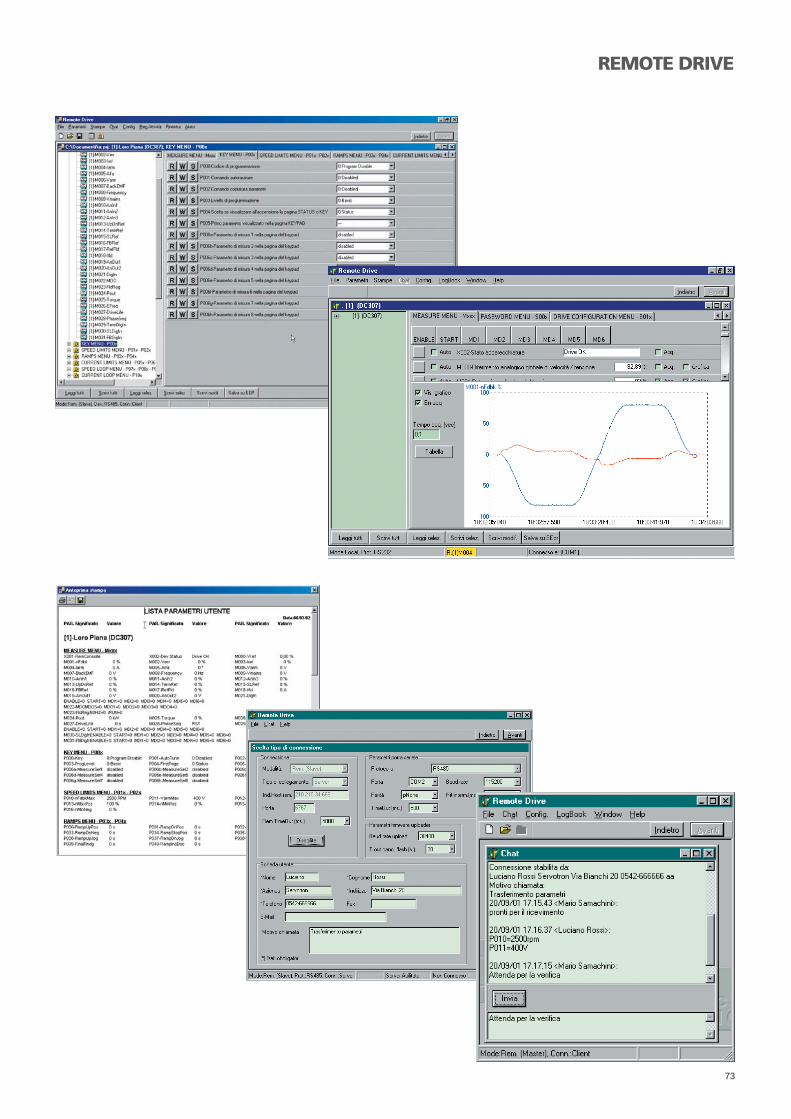
73
REMOTE DRIVE

74
ApplicazioniApplications

75

76
HVAC
Caratteristiche principaliMain features
- Ampia gamma di potenza e IP54 2.2 - 250 kW (690VAC) 200-690VAC.
- IP54 standard. Montaggio a muro anche accanto al motore.- Display alfanumerico a 4 linee. Semplicità di navigazione, con-
fi gurazione, monitoraggio e salvataggio dei parametri per un utilizzo facile e veloce.
- 5 metodi di controllo (IFD, VTC, FOC, SYN, RGN) disponibili su ciascun azionamento Sinus Penta per soddisfare le esigenze più diverse.
- Filtro EMC integrato. Non è necessario aggiungere alcun fi ltro esterno.
- PID con funzione Sleep e Wake-up.- Secondo PID e PID 2-zone.- I/O con funzioni di comparatore interno. Non è necessario al-
cun componente aggiuntivo.- Funzionalità di comunicazione integrate.- Funzione fi re mode- RTC (Real Time Clock) integrata con scheda opzionale
- Wide power and voltage range IP54 2.2 – 250 kW (690VAC) 200-690VAC..
- P54 standard solutions. Can be wall-mounted even close to the motor.
- 4-line alphanumeric display. Allows easy navigation, confi guration, monitoring and parameter storage – easy to use and saves time.
- 5 built-in control methods (IFD, VTC, FOC, SYN, RGN). The same drive can suit the most diverse solutions.- Built-in EMC fi lter. No additional external fi ltering required.- Built-in EMC fi lter. No additional external fi ltering required.- 2nd PID and 2-zone PID.- Extensive I/Os with internal comparator functions. No need
for additional components.- On-board communication.- Fire mode operation.- RTC (Real Time Clock) integrated with opcional card.
Applicazione utilizzata per riscal-damento, ventilazione e condizio-namento dell’aria
Gli standard IP54 e IP20 offerti dalla linea SINUS PENTA si adat-tano perfettamente alle applicazioni HVAC.Gli azionamenti Sinus Penta incorporano funzioni PID avanzate per il controllo automatico e sono in grado di comunicare con i più comuni bus di campo per il controllo e il monitoraggio di Building Management Systems (sistemi per la gestione integra-ta di tutte le funzioni tecnologiche di un edifi cio). Le modalità Fire Mode e doppio PID consentono il funzionamento prolun-gato durante i periodi più critici, garantendo la funzionalità, la robustezza e l’affi dabilità richieste. È disponibile la funzione Speed Search per l’inseguimento della velocità del motore.
Application used for heating, ven-tilation and air condictioning
The standard IP54, as well as IP20, SINUS PENTA solution is perfectly suited to HVAC applications.The drive incorporates advanced PID functions for automa-tic control and extensive fi eld buses communications to allow control and monitoring from a Building Management System. The drive implements the Fire Mode function and the dual PID functions for extended operation during critical periods, thus providing the robustness and reliability required.The drive also features the Speed Search function, allowing the drive to reach the motor speed when it is started on a rotating load.
CondizionatoriChiller
Ventilatori a torrettaSistemi di pompaggio
Air HandlerWater Condenser Chiller
Cooling Tower Fan Pump

77

78
Il crescente bisogno di effi cienza energetica ha spinto Elettroni-ca Santerno nello sviluppo di prodotti ed accessori per soddisfa-re l’esigenza di sistemi performanti per l’utilizzo nell’intero ciclo dell’acqua. Il 20% del fabbisogno di energia è utilizzato nelle stazioni di pompaggio. Le stazioni di pompaggio oltre che as-sicurare affi dabilità e potenza, devono garantire la maggior ef-fi cienza a riduzione dei costi necessari all’approvvigionamento idrico ed il trattamento delle acque.
Risparmio energeticoLa continua crescita dei costi dell’energia elettrica e la con-seguente esigenza di risparmio energetico, trova soluzione nell’utilizzo degli inverter. L’effi cienza energetica, la robustezza, l’attenzione alle richieste del settore, la completezza degli acces-sori necessari alla realizzazione di sistemi affi dabili e performanti fanno di Elettronica Santerno il partner ideale per le grandi reti di trasporto
Semplicità d’utilizzo per l’utenteL’inverter Elettronica Santerno è semplice da utilizzare, il Sw si confi gurazione guidata permette una programmazione rapida delle funzioni essenziali. L’interfaccia multilingue permette un’ approccio immediato per la confi gurazione di nuovi sistemi e l’instalalzione ad aggiornamento dei sistemi esistenti.
Connettività e integrazione nei sistemiL’affi dabilità e sicurezza vengono tipicamente realizzati da siste-mi di controllo. Elettronica Santerno risponde a questa esigenza con l’utilizzo dei più comuni bus di campo (PROFIDRIVE, PROFI-BUS, CANOPEN, DEVICENET, ETHERNET, LONWORKS, ecc).La riduzione dei costi di connettività del sistema può essere ot-tenuta mediante l’utilizzo di espansioni I/O sull’inverter riportate su interfaccia seriale
Linearità di pressioneL’utilizzo dei sistemi elettronici applicati all’avviamento dei mo-tori elettrici eliminano le brusche variazioni di pressione nelle condotte dovute al collegamento diretto dei motori alla rete elettrica. La regolazione di pressione e le funzioni di ENERGY SAVER abbattono i costi di manutenzione, di realizzazione e di esercizio degli impianti. L’Utilizzo delle apparecchiature Elettro-nica Santerno trova riscontro nell’intero ciclo dell’acqua.
The increasing demand of energy effi ciency has led Elettronica Santerno to design products and accessories to fulfi l the require-ments for performing systems exploiting the whole water cycle. 20% of the energy demand is exploited for pumping stations. Pumping stations shall ensure the greatest reliability and pum-ping capacity, as well as the most dramatic cost decrease for water supply and water treatment.
Energy savingUsing inverters is the best solution to limit the increasing expen-siveness of the electric energy while enhancing energy saving.Energy effi ciency, robustness, custom solutions, complete ran-ge of accessories required for the manufacture of reliable and performing systems are Elettronica Santerno’s assets for large transport networks.
User-friendlinessThe inverters designed and manufactured by Elettronica Santer-no are very simple to use. The application wizard allows quick programming of the basic functions. The multilingual interface allows easy confi guration of new systems and easy update of the existing systems.
Connectivity and system integrationControl systems typically feature reliability and safety.Elettronica Santerno meets reliability and safety requirements by using the most common fi eld buses (PROFIDRIVE, PROFIBUS, CANOPEN, DEVICENET, ETHERNET, LONWORKS, etc).The costs for connectivity can be reduced by using additional I/Os on the inverter and made available on the serial link as well.
Pressure linearityThe electronic systems applied to motor drives suppress abrupt pressure variations in piping otherwise occurring when motors are connected directly to the mains.Pressure adjustment and ENERGY SAVER functionality dramati-cally reduce manufacturing costs, operation costs and mainte-nance costs.Elettronica Santerno products fi t any stage in water cycle.
WATER

79
Purifi cation plants require a wide range of products pertaining to: Pumps - Compressor - Augers - Fans - Mixers
Underground water is pumped through submerged electropumps needing quick start up and very accurate control and adjustment
High pressure pumps areu sed in the desalination plants to obtain drinkable water.
The pumping stations pump water for a long distance and require very large power output.
The watering systems require even power delivery for optimum energy consumption

80
Santerno offre un pacchetto completo di soluzioni, prodotti e servizi per l’intero processo produttivo nell’industria del cemento.
Le infrastrutture degli impianti, considerate parti integranti degli impianti stessi, includono anche consulenze ingegneristi-che fornite direttamente dal costruttore o dalla rispettiva rete di vendita. In questa ottica, Santerno garantisce la scelta delle tecnologie più appropriate e il dimensionamento corretto del-le apparecchiature, con enormi vantaggi economici nel breve e lungo periodo.
Santerno offers a comprehensive package of solutions, products and services for the complete primary production chain for the cement industry.
Considered as integrant to the plants, facilities also include en-gineering consulting, either directly from the factory or from its sales network worldwide. Santerno ensures choosing the most suitable technologies and products, as well as their correct di-mensioning. This leads to dramatic money savings and adds up to a signifi cant enhancement in a plants’ economy over its lifecycle.
CEMENT

81
MININGAzionamenti di media e bassa tensione per l’industria mineraria e del cemento.
Attiva fi n dal 1970, Santerno è tra i maggiori produttori mon-diali di azionamenti a velocità variabile. La sua esperienza nello sviluppo e nelle applicazioni sul campo di azionamenti a velocità variabile, accompagnati dalla continua ricerca dell’innovazione, garantisce il miglioramento costante delle prestazioni e della produttività degli impianti.Gli azionamenti Santerno di media tensione (sviluppati con il si-stema Step Down-Step Up) soddisfano tutte le esigenze dell’indu-stria mineraria e del cemento. L’installazione è semplice e veloce. L’utilizzo di soli componenti standard sempre disponibili a magaz-zino in tutte le fi liali Santerno consente inoltre una manutenzione tempestiva, accrescendo la qualità e l’affi dabilità del prodotto.
Medium and Low Voltage Drives for Cement, Mining and Minerals.
Santerno is a global leading supplier of variable speed drives. Its extensive experience and history, started in 1970, helps ce-ment, mining and minerals customers around the world to im-prove plant performance and production.Santerno medium voltage drives, developed with the Step Down-Step Up solution, offer the perfect solution for the re-quirements of the cement, mining and mineral industries in-stalling standard drives.This solution allows quick installation and maintenance, as only standard components are used, which are available in Santer-no’s stocks worldwide. This solution also enhances the product quality and reliability.

82
REGENERATIVE
Generazione di energiaBanchi provaGru e verricelliAvvolgitori
TrasportatoriScale mobiliPresseAscensori
Power generationTest benchesCranes and winchesWinders
ConveyorsEscalatorsPressesElevators
Mark for both the Canadian and US Markets
Gli azionamenti rigenerativi (o a quattro quadranti) sono in gra-do di recuperare in rete l’energia (potenza). Il SINUS PENTA of-fre la funzione rigenerativa integrata che consente di rigenerare potenza con cosfi unitario (applicazione Active Front-End). L’on-da sinusoidale pura consente inoltre di portare drasticamente il THDI sotto il 5% e di ottenere un THDV = 0. Anche in questo caso Santerno offre la soluzione ideale: gli azionamenti SINUS PENTA standard, oltre a mantenere la minima giacenza possibile in magazzino, evitano l’utilizzo di ingombranti unità di frena-tura e resistenze, componenti alquanto costosi e non sempre perfettamente affi dabili, recuperando l’energia in rete senza dispersione di calore dovuta all’energia non utilizzata.
Frenatura rigenerativaMetodo di frenatura secondo il quale l’energia meccanica pro-dotta dal carico viene convertita in energia elettrica e rigenerata in rete. Il motore funziona come generatore.Applicazioni tipiche sono gru, carriponte e sistemi di solleva-mento in genere che richiedono un THDI inferiore al 5%.
Mark for both the Canadian and US Markets
A regenerative AC drive (also known as four-quadrant) is a drive capable of recovering energy (power) back to the mains. The Regenerative SINUS PENTA allows regenerating a PF=1 (pure AFE application). The pure sinusoidal waveform also al-lows dramatically reducing the THDI <5% and allows obtai-ning THDV = 0.Even in that case, this function is implemented in the stan-dard SINUS PENTA drives; besides keeping the stock level at a minimum, they also allow getting rid of braking units and resistors, which are very expensive and sometimes unreliable components generating unwanted and excessive heat.
Regenerative brakingThe mechanical energy produced from the load is converted into electric energy and is regenerated back into the AC mains. The Motor operates as a generator. Typical examples: cranes, lifts and all the applications where a THDI lower than 5% is required.
Compliant with: CSA C22.2 No. 107.1-01 (2006) General Use Power Supplies / UL 1741 (2010) Inverters, Converters, Controllers and Interconnection System Equip-ment for Use With Distributed Energy Resources / IEEE 1547 (2003) Interconnecting Distributed Resources with Electric Power Systems

83

84
LIFTIl principale vantaggio del SINUS K LIFT è il software dedicato per sole applicazioni ascensoristiche, che consente di soddisfare le più comuni esigenze di sollevamento.
Santerno SINUS K LIFT (provided with a built-in specifi c software for elevators only) offers specially-designed frequency conver-ters to satisfy most of the needs of lift customers who do not need all the other features of a general purpose drive.
- Controllo di motori asincroni - Modalità di controllo motore ad anello chiuso e ad anello aperto- Design compatto con dispositivo di frenatura integrato- Filtro EMC di Categoria C1-2-3 integrato - Silenziosità del motore grazie alla frequenza di commutazi ne
elevata e al metodo di modulazione random proprietario- Controllo dei ventilatori per una minore rumorosità dell’azionamento- Parametri di velocità in [m/s]
- Asynchronous motor control- Closed loop and open loop motor control modes- Compact design with integrated brake chopper- Integrated C-level EMC fi lter - Low motor noise due to high switching frequency and specifi c random switching frequency- Fans control to reduce drive noise- Lift speed parameters in [m/s
Caratteristiche principaliMain features

85
Santerno è il partner ideale per l’ammodernamento e l’installa-zione di innovativi sistemi di automazione per le applicazioni in campo di sollevamenti. La lunga esperienza in questo campo ha permesso a Santerno di implementare nel SINUS PENTA STAN-DARD tutte le funzionalità necessarie per queste applicazioni, come il controllo FOC a circuito chiuso, il controllo Rigenerativo, il controllo anticaduta del carico, che consentono di operare in tutta sicurezza. Grazie al know-how proprietario, Santerno è in grado di fornire un servizio altamente qualifi cato, prima e dopo l’installazione, che accompagna l’eccellenza dei propri prodotti.
Il sistema garantisce- Disponibilità- Produttività- Sicurezza- Bassi costi operativi
Santerno is the ideal partner for the modernization as well as the installation of new automation systems for cranes. The STAN-DARD SINUS PENTA drives feature the closed-loop FOC control, the Regenerative function and Fall prevention of the connected load. This allows operating under totally safe conditions. Santer-no can provide high qualifi ed service before and after installa-tion thanks to a high knowledge and excellent features of the product developed for this application specifi cally.
The system offers- Availability- Productivity- Safety- Low operational costs
CRANES

86
MV STEP DOWN - STEP UPGli azionamenti Santerno di media tensione (sviluppati con il si-stema Step Down-Step Up) soddisfano tutte le esigenze dell’in-dustria mineraria e del cemento. L’installazione è semplice e veloce. L’utilizzo di soli componenti standard sempre disponi-bili a magazzino in tutte le fi liali Santerno consente inoltre una manutenzione tempestiva, accrescendo la qualità e l’affi dabilità del prodotto.
Santerno medium voltage drives, developed with the Step Down-Step Up solution, offer the perfect solution for the requirements of the cement, mining and mineral industries installing standard drives. This solution allows quick installation and maintenance, as only standard components are used, which are available in Santerno’s stocks worldwide. This solution also enhances the product quality and reliability.
Caratteristiche principaliMain features
Convertitore di frequenza per motori - 30...3.000 kW, 1 kV ÷ 15 kV mediante trafo step up- applicazioni a coppia quadraticaPerdite massime a pieno carico- Inverter: 60 kW- Filter: 6 kWContenuto dell’armonica fondamentale sulla tensione di uscita: 95% THD < 12%Basso livello di armoniche in rete
Frequency converter for motors- 30...3.000 kW, 1 kV ÷ 15 kV via step up trafo- square torque applicationsMaximum losses at full load- Inverter: 60 kW- Filter: 6 kWFundamental wave content of output voltage: 95%THD < 12% Reduced level of harmonics on the AC mains
Schema a blocchiBlock diagram

87

88
AccessoriAccessories

89
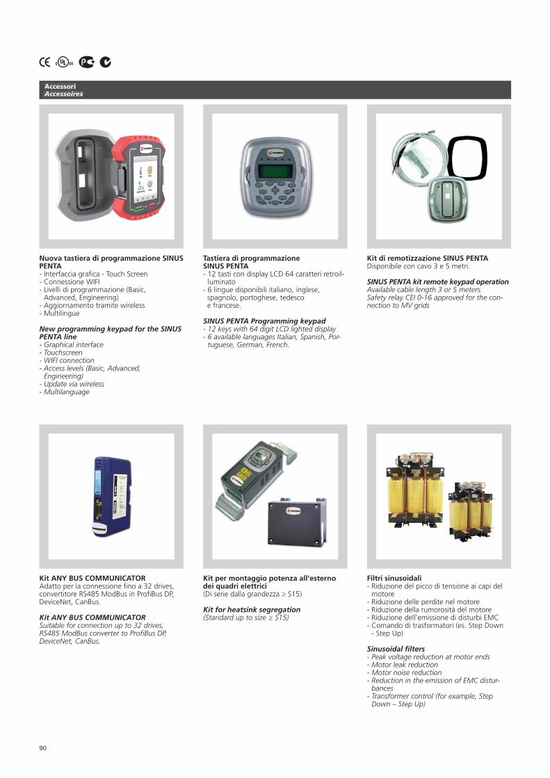
90
AccessoriAccessoires
Tastiera di programmazione SINUS PENTA - 12 tasti con display LCD 64 caratteri retroil-
luminato- 6 lingue disponibili italiano, inglese, spagnolo, portoghese, tedesco e francese.
SINUS PENTA Programming keypad- 12 keys with 64 digit LCD lighted display- 6 available languages Italian, Spanish, Por-
tuguese, German, French.
Kit di remotizzazione SINUS PENTADisponibile con cavo 3 e 5 metri.
SINUS PENTA kit remote keypad operationAvailable cable length 3 or 5 meters.Safety relay CEI 0-16 approved for the con-nection to MV grids
Nuova tastiera di programmazione SINUS PENTA- Interfaccia grafi ca - Touch Screen- Connessione WIFI- Livelli di programmazione (Basic,
Advanced, Engineering)- Aggiornamento tramite wireless- Multilingue
New programming keypad for the SINUS PENTA line- Graphical interface- Touchscreen- WIFI connection- Access levels (Basic, Advanced,
Engineering)- Update via wireless- Multilanguage
Kit per montaggio potenza all’esterno dei quadri elettrici (Di serie dalla grandezza ≥ S15)
Kit for heatsink segregation (Standard up to size ≥ S15)
Filtri sinusoidali- Riduzione del picco di tensione ai capi del
motore - Riduzione delle perdite nel motore - Riduzione della rumorosità del motore - Riduzione dell’emissione di disturbi EMC - Comando di trasformatori (es. Step Down
- Step Up)
Sinusoidal fi lters- Peak voltage reduction at motor ends - Motor leak reduction - Motor noise reduction - Reduction in the emission of EMC distur-
bances - Transformer control (for example, Step
Down – Step Up)
Kit ANY BUS COMMUNICATORAdatto per la connessione fi no a 32 drives, convertitore RS485 ModBus in Profi Bus DP, DeviceNet, CanBus.
Kit ANY BUS COMMUNICATORSuitable for connection up to 32 drives, RS485 ModBus converter to Profi Bus DP, DeviceNet, CanBus.

91
AccessoriAccessoires
Modulo di frenatura Per taglie ≥ S41
Braking module For sizes ≥ S41
Resistenza di frenaturaIn estruso d’alluminio IP55
Braking resistorExtruded aluminium IP55
Interfaccia rigenerativaInduttanze per applicazioni con inverter rigenerativo
Regenerative interfacInductances for applications with regenerati-ve inverter
Resistenza di frenatura Di lamina d’acciaio in BOX IP23
Braking resistorLaminated stainless steel in cabinet IP23
Convertitori CA/CC Convertitori analogoci monofasi AMS 90
AC/DC convertersAnalog converters AMS 90
Resistenza di frenaturaA fi lo contenitore IP20
Braking resistorWire container IP20

92
AccessoriAccessoires
InduttanzeElettronica Santerno dispone di unaampia gamma di induttanze:- Induttanze di linea- Induttanze lato motore- Induttanze ad alta frequenza- Induttanze d’ingresso e d’uscita (Dispo-
nibili anche in grado di protezione IP54)- Induttanze e Interfaccia per applicazioni con
inverter rigenerativo
InductorsElettronica Santerno has a wide rangeof inductors:- Input chokes- Motor chokes- High frequency coke- Input and output inductances (Available
with enclosure up to IP54)- Inductances and Interfaces for regenerative
inverter application
Accessori per protezione IP20/NEMA 1 di convertitori e impedenze
IP20/NEMA 1 protection devices forconverters and inductors
Filtri EMCElettronica Santerno dispone di una ampia gamma di fi ltri EMC:- Filtri singola cella- Filtri doppia cella- Filtri a bassa corrente di fuga- Filtri toroidali in ferrite
EMC fi lterElettronica Santerno has a wide rangeof EMC fi lters:- Single function fi lters- Double function fi lters- Low leakage current fi lters- Ferrite ring fi lters

93

Worldwide
HEADQUARTERS
Elettronica Santerno S.p.A.Strada Statale Selice, 4740026 – Imola (Bologna) – ItalyT +39 0542 489711F +39 0542 [email protected]@santerno.comsanterno.com
Milan Offi cesVia Giotto, 420040 – Cambiago (Milan) ItalyT +39 02 95138126F +39 02 [email protected]
Rome Offi cesPiazza Marconi, 1500144 - Rome - ItalyT +39 06 32803912/13F +39 06 [email protected]
Munich Offi cesElisabethstr. 91 80797 - Munich - Germany T +49 (0)89 5908 2376 F +49 (0)89 5908 1200 [email protected]
DIRECT BRANCHES
Santerno ZAOUl. Sherbakovskaya, 53Building 16 – Offi ce 205/206105187 – Moscow, RussiaT +7 495 5457352F +7 495 [email protected]
Eletrônica Santerno Indústria e Comércio Ltda.Av. Pereira Barreto, 1395 - Torre SulSanto André - São Paulo - BrazilCep. 09190-610T +55 11 4422-4540(Ofi cina Comercial)T +55 35 3471 7828(Factory - Sta. Rita Sapucai - MG)[email protected] www.santerno.com.br
Elettronica Santerno España SLUCuadra Lairón, 117aCiudad del Transporte12006 – Castellón de la PlanaCastellón – SpainT +34 964 250385 - +34 609 906028F +34 964 341 [email protected]
Santerno Inc.One Market St.Spear Tower, Suite 3600San Francisco, CA94105 - U.S.A.T +1 [email protected]
SANTERNO ENGLANDTechnical Solutions 24 Seven Limited Unit 20Oldfi Eld Business ParkBirrell Street - FentonStoke-On-TrentStaffordshireSt4 3peT. +44 1782 317379F. +44 1782 [email protected]
SANTERNO IRELANDAvonMore Electrical WholesaleKillarney Road,Rosekeen Mallow CO. CORKT. +353 2247477F. +353 [email protected]
SANTERNO SPAINMaquinaria Electrica Bilbao S.A.Barrio Elorrieta, 9 - Apartado 76448015 - BilbaoT. +34 944474900F. +34 [email protected]
SANTERNO GERMANYExclusive AgentIas-Strothmann E.K.Dorstener Strase,1333649 BielefeldT. +49 (521) 47 98 04F. +49 (521) 47 98 [email protected]
SANTERNO PORTUGALZembe LdaAlameda Das LInhas De Torres, 151-C1750 LisboaT. +35 1217520180F. +35 [email protected]
SANTERNO POLANDppuh eldar45-531 Opole, Ul. Morcinka 51T. +48 (77) 442-04-04T./F. +48 (77) [email protected]
DISTRIBUTOR

SANTERNO TURKEYTesan Elektrik Otomasyon Tic. Ltd. Sti.Perpa Ticaret Merkezi A Blok Kat. 2No: 9/0034 34384 Okmeydani - Sisli / ISTANBULT. + 90 212 221 48 48 PbxF. + 90 212 221 17 [email protected]
SANTERNO CYPRUSMangrinox S.A.14, GrEvenon Street11855 AthensT. +30 210 3423201-3F. +30 210 3459928, [email protected]
SANTERNO GREECEMangrinox S.A.14, Grevenon Street - 11855 AthensT. +30 210 3423201-3F. +30 210 3459928, [email protected] S.A.3, Galikou & Dafnis St [email protected]
SANTERNO ROMANIAM.E.D.E.E.A. International Srl119 Sabinelor Str., Sect.5050852 – BucharestT. +40 21 7812113 / 31 [email protected]@santernopartner.comwww.medeea-international.ro
SANTERNO UKRAINAItal-Tecno LtdTupoleva, 1904128 KievT. +38 0444222113F. +38 [email protected]@santernopartner.comwww.ital-tecno.com.ua
SANTERNO LITHUANIAAgavaGedimino, 4703000 KaunasliT. +37 037202410F. +37 [email protected]@santernopartner.com
SANTERNO BELARUSAvtoprivod Double Liability CompanyV. Gostinec Street Builing 143b-501222310 Molodechno BelarusT. +375 1773 54634F. +375 29 [email protected]
SANTERNO SERBIAMomentum d.o.o.Kralja Petra I br. 4822000 Sremska Mitrovica SerbiaT. +381 22 625 010F. +381 22 625 [email protected]
SANTERNO TUNISIASeaSociete D’electronique Et D’automatisme400 Avenue Kaled IBN EL OualidDouar Hicher - ManoubaT. +21671820 F. [email protected]
Sne SometelCtr Said, Av. H. Bourguiba2033 MegrineT. +216 71434154F. +216 [email protected]
SANTERNO EGYPTAdvanced Electronic Engineering26 Rabaa Blds., Nozha St.Nasr CityEgypt, CairoT. +20 (202) 4181580F. +20 (202) 4159265Hot-Line: [email protected]
SANTERNO SAUDI ARABIAA.M.P.S.Al Mutlaq BLDG 3AL-KHOBAR 31952T. +966 38821055F. +966 [email protected]
SANTERNO THAILANDBrainics Technology Co. Ltd.48/184-185 MOO1Ramkhamhaeng RoadSapansoong - Bangkok10240 - ThailandT. +66 2729 4833F. +66 [email protected]
SANTERNO MALAYSIAHi-Tech Drives (M) Sdn Bhd36, Jalan Taboh 33/22,Shah Alam Technology Park,Seksyen 33, 40400 Shah Alam,Selangor Darul Ehsan MalaysiaT. + 60 3 - 5124 9498F. + 60 3 - 5124 9478Mobile: + 60 19 - 211 [email protected]
SANTERNO CHINAIecco Technology Co. LtdBusiness Incubator Center BuildingJiang Nan Electronic Science & Technology Park362000 Quanzhou-ChinaT. +86 (595) 28055235F. +86 (595) [email protected]
SANTERNO USACerus Industrial Inc.3101 Sw 153 Drive,Suite 318Beaverton,Or 97006T.+1503-646-2500F.+1 [email protected]
SANTERNO CANADATeco-WesTinghouse Motors (Canada) Inc.18060 - 109th Avenue,Edmonton, AlbertaT5S 2K2T. +1-800-661-4023F. [email protected]
SANTERNO ARGENTINAMotortech S.A.C. M. Ramírez 2555 – Capital Federal – Buenos AiresT. +54 -11- 4918-2299F. +54-11- [email protected]@santernopartner.com
Worldwide

SANTERNO VENEZUELACorporacion Teknomaq C.a.Calle La Colina, Edf. Residencia Las Acacias piso Mezz.Local B y C, Urb. Las Acacias 1040Caracas - VenezuelaT. +58 212 6936310/ 6933540F. +58 212 [email protected]@santernopartner.com
SANTERNO MEXICORepinelCalle Cacamatzin N°6955Fracc. Del Real 32660 - Juarez ChihuahuaT.+52 (656) [email protected]/City: Chihuahua, Sonora, Baja California,Monclova, Piedra Negras
NojoxtenAv. Santa Margarita #283Col. Santa Margarita ZapopanJalisco 45140T.+52(33) [email protected]/City: Jalisco, Nayarit, MichoacanGuanajuato, Colima
Interdos S.APablo Gonzales 729-2Col. Mitra Sur 64020Monterrey, N.LT. +52 (81) 83 334083F. +52(81) 83 [email protected]/City: Nuevo Leon, Tamaulipas, San LuisPotosi Saltillo-Ramos Arizipe, Torreon-Gomez Palacio
PropysaPresa Solis 50 – Col. IrrigaciónC.P. 11500,D.F - MexicoT. +52 (55) 5557-0814F. +52 (55) [email protected]/City: Edo De Mexico, D.F., Tlaxcala, Puebla,Queretaro, Morelos, Hidalgo, Guerrero, Oxaca YAguascalientes.
SANTERNO PERÙObras Electricas S.AAv.Mrcal.O.RBenavidas 1215LimaT.+51(1) 619 [email protected]@santernopartner.com
SANTERNO CHILEDimet Ltda.Coronel Alvarado 2384Comuna IndependenciaSantiago De Chile - ChileT. +56 2 [email protected]
SANTERNO REPUBLICA DOMINICANAMando Y Regulación IndustrialColinas del Seminario V, Manzana C#12Los Rios - 10606 - Santo DomingoT + 1809 561-5025F + 1829 [email protected]@santernopartner.com
SANTERNO AUSTRALIA & NEW ZELANDNhp Electrical Engineering Products Pty Ltd43-67 River StreetRichmond, Victoria 3121T. +61 3 9429 2999F. +61 3 9429 [email protected]
SANTERNO INDIABch Electric Limited1105, New Delhi House27, Barakhamba RoadNew Delhi - 110 001, IndiaT. +91-11-23316029F. [email protected]
SANTERNO SOUTH-AFRICAU&S Power Electronics36 Telfort StreetDuncanvilleVereeniging 1939 South AfricaT. +27164220760F. [email protected]
SANTERNO NORWAYStadt AS og SCHORCH Norge AsMoloveien 2, N-6083 Gjerdsvika t. +47 70 02 58 [email protected]
SANTERNO AUSTRIAGRUBER ELECTRIC GesmbH A 1230 Wien, Eduard Kittenberger Gasse 97/2t.+43-1-8692339-0f.+43-1-8651875offi [email protected]@santernopartner.comwww.gruber-electric.at
SANTERNO BHUTAN, BANGLADESH, NEPAL,SRI LANKA, MALDIVESBCH ELECTRIC [email protected]
SANTERNO SWAZILAND, LESOTHOU&S POWER [email protected]
SANTERNO SINGAPORE [email protected]
SANTERNO MOROCCOEletec [email protected]
SANTERNO BELGIUM Ets H. Focquet & Cie Sa - [email protected]
OTHER PARTNERS
Worldwide

Strada Statale Selice 4740026 Imola (BO) - ITALY t.+39 0542 489711f.+39 0542 489722 [email protected]
Il ca
talo
go
è s
og
get
to a
mo
difi
ch
e se
nza
pre
avvi
so -
Th
is c
atal
og
ue
is s
ub
jet
to c
han
ges
wit
ho
ut
pri
or
no
tice
- 1
5139
0025
IT-U
S