girder alignment in the diamond storage ring
TRANSCRIPT
GIRDER ALIGNMENT IN THE DIAMOND STORAGE RING
M. Apollonio, W. J. Hoffman, A. J. Rose, A. Thomson, Diamond Light Source, Oxfordshire, U.K.R. Bartolini, Diamond Light Source, Oxfordshire, U.K. and
John Adams Institute, University of Oxford, U.K.
AbstractA model of the Diamond Storage Ring describing the
misalignment of its 74 girders in terms of displacementsand rotations is used to predict the orbit distortions and cor-rector magnet strengths needed for a zero orbit. Using thedata from a survey we compare the effect of a pure magnetmisalignment with the natural orbit of the machine. Testswith displaced girders meant to produce a reduction in cor-rector strength are introduced. Comparison with data ob-tained from the actual move of the girders are presentedand discussed.
INTRODUCTIONDiamond is a 3rd generation synchrotron light source,
fully operational since 2007 [1]. It features a beam of 3GeV with a typical 2.7 nm emittance and is presently op-erated in a low coupling mode (0.3 %) at a current of 300mA. The initially six-fold symmetric 24 cell structure withDouble Bend Achromats (DBA) sitting on girder tripletshas been modified with the introduction of double mini-beta sections in straights 9 and 13, which required two extramid-straight girders hosting quadrupole doublets to matchthe new optics, for a total of 74 girders in a 561.6 m longcircumference [2].
Using survey data taken between January 2012 and Jan-uary 2013 we study the effect of orbit distortions gener-ated by misalignment and predict the change in correctorstrength due to girder moves.
We report on some actual tests done on the machine, bothin the vertical and in the horizontal plane and suggest aprocedure for the alignment of the storage ring.
SURVEYMost of the magnets in the Storage Ring (SR) are
mounted on three types of girders that also host beam po-
Figure 1: Top view of a standard girder-2. The red dotsmark the positions of the monuments used in the survey.
sition monitors (BPMs) and corrector magnets (CMs) em-bedded in the sextupoles. Each cell has two primary BPMs,mounted on the floor and therefore decoupled from thenearby girders. Girder positions can be surveyed by means
of monuments mounted at the edges of every girder (seeFig. 1). In a typical survey, both planimetric (xy) and al-timetric (z) views are provided, allowing a comparison be-tween the actual monument positions and the design con-figuration. The instrumental precision on monument posi-tions varies along the ring, with typical figures of 100 μmfor the horizontal plane and 50 μm for the vertical one.
166 168 170 172 174 176 178 180 182
−200
0
200
side view − CELL 8
S (m)Y
(μm
)
G1 G2 G3
quadrupolesdipoles
sextupoles
x monument actualpositions(survey)
o monument nominalpositions(best fit vertical plane)
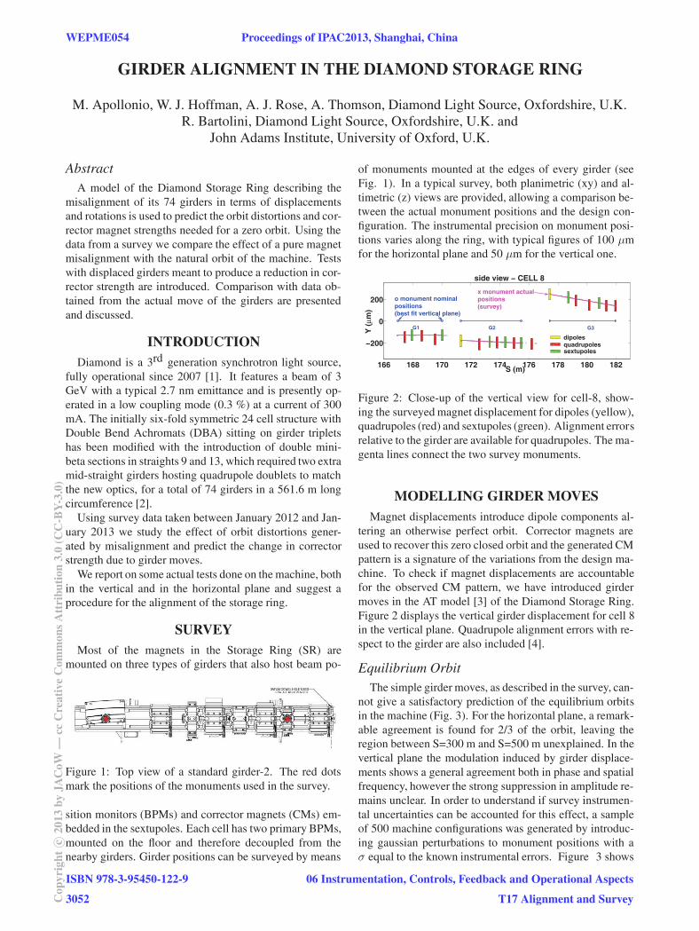
Figure 2: Close-up of the vertical view for cell-8, show-ing the surveyed magnet displacement for dipoles (yellow),quadrupoles (red) and sextupoles (green). Alignment errorsrelative to the girder are available for quadrupoles. The ma-genta lines connect the two survey monuments.
MODELLING GIRDER MOVESMagnet displacements introduce dipole components al-
tering an otherwise perfect orbit. Corrector magnets areused to recover this zero closed orbit and the generated CMpattern is a signature of the variations from the design ma-chine. To check if magnet displacements are accountablefor the observed CM pattern, we have introduced girdermoves in the AT model [3] of the Diamond Storage Ring.Figure 2 displays the vertical girder displacement for cell 8in the vertical plane. Quadrupole alignment errors with re-spect to the girder are also included [4].
Equilibrium OrbitThe simple girder moves, as described in the survey, can-
not give a satisfactory prediction of the equilibrium orbitsin the machine (Fig. 3). For the horizontal plane, a remark-able agreement is found for 2/3 of the orbit, leaving theregion between S=300 m and S=500 m unexplained. In thevertical plane the modulation induced by girder displace-ments shows a general agreement both in phase and spatialfrequency, however the strong suppression in amplitude re-mains unclear. In order to understand if survey instrumen-tal uncertainties can be accounted for this effect, a sampleof 500 machine configurations was generated by introduc-ing gaussian perturbations to monument positions with aσ equal to the known instrumental errors. Figure 3 shows
WEPME054 Proceedings of IPAC2013, Shanghai, China
ISBN 978-3-95450-122-9
3052Cop
yrig
htc ○
2013
byJA
CoW
—cc
Cre
ativ
eC
omm
onsA
ttri
butio
n3.
0(C
C-B
Y-3.
0)
06 Instrumentation, Controls, Feedback and Operational Aspects
T17 Alignment and Survey

0 100 200 300 400 500−0.025
−0.015
−0.005
0.005
0.015
0.025
S (m)
X−or
bit (m
)
monument error orbitmachine orbit1−σ contourmodel
best χ2
0 100 200 300 400 500−0.01
−0.005
0
0.005
0.01
S (m)
Y−or
bit (m
)
Figure 3: Expected natural orbits from variations in monument positions due to survey instrumental errors for both theplanimetric view (top) and the vertical view (bottom).
the resulting 500 orbits (gray) together with the solutioncorresponding to the surveyed monuments (solid red) andthe equilibrium orbit from the machine (blue). The dashedred line is the 1-σ orbit envelope from the simulated sam-ple of machine configurations. A χ2 search through thesample is performed to find the orbit closest to the one inthe machine (green line). We find that in the horizontalplane instrumental errors may account for the observed or-bit discrepancies (best match solution well within the 1-σenvelope). In the vertical plane the best match solution isoutside the 1-σ envelope. For this case, the correspond-ing girder positions are in general not too far from the sur-
10 20 30 40 50 60 70−200
−100
0
100
200
girder n.
pit
ch
(μ
rad
)
best χ2 solutionsurveyed points
Figure 4: Girder pitch angles. Survey points are shown inred, together with the error bars from instrumental mea-surements of the monuments. The blue dots show the so-lution whose vertical orbit better matches the one in themachine.
veyed values, with the exception of few outliers, as shownin Fig. 4 for the girder pitch angles. As a general conclusionof this part, it is felt that pure girder movements might notbe the sole responsible for the actual equilibrium orbit andfor the corresponding CM pattern. On the other hand, con-trolled changes in the position of a girder should producewell defined changes in the orbit and hence in the correctormagnets. This will be the focus of the next sections of thepaper.
Prediction on Corrector Strengths
The non-zero equilibrium orbit at the BPMs generatedby magnet displacements can be fed into the orbit correc-tion algorithm, usually running online, to calculate the CMset bringing the orbit back to zero at the BPMs. The ATalgorithm is based on the usual BPM Response Matrix andfinds the correcting CM set via an iterative procedure.
TESTS ON THE MACHINE
A girder move is achieved by adjusting the position offive independent motorised cams that resolve into the mainspatial degrees of freedom (sway, heave, roll, yaw andpitch). The EPICS based motion control system can, inprinciple, be operated from the control room. However, atthis early stage of operation every move is performed underlocal control via a laptop and a portable rack containing themotion control components (motion controller and ampli-fiers). In a typical girder move session, positions and incli-nations are also monitored by the survey team, enhancingthe confidence in the measurement. A protection system,based on pairs of linear travel sensors, has been imple-mented to ensure that any possible motion control failurewill not result in damage to the inter-girder bellows. If pos-sible, before and after the move, a Beam Base Alignment(BBA) is run in order to align the BPMs to the quadrupolecentres and avoid systematics in the CM values. So far inDiamond, we have tested the effects of three girder moves,one in the horizontal plane and two in the vertical plane.
Horizontal Move
On December 4th 2012, we moved girder 2 in cell 3(C3G2) by a horizontal sway of +324 μm. This choice wasmotivated by the zero impact of the move over nearby beamlines and by the attempt at reducing gaps between adjacentgirders with a single move (see Fig. 5).
Proceedings of IPAC2013, Shanghai, China WEPME054
06 Instrumentation, Controls, Feedback and Operational Aspects
T17 Alignment and Survey
ISBN 978-3-95450-122-9
3053 Cop
yrig
htc ○
2013
byJA
CoW
—cc
Cre
ativ
eC
omm
onsA
ttri
butio
n3.
0(C
C-B
Y-3.
0)

30 40 50 60 70 80 90−1500
−1000
−500
0 planimetric view − linearized
S (m)
ΔX (
um
)C4C2 C3
C3G2heave = +324 μm
Figure 5: Planimetric view of the zone around cell 3. Thesway of +324 μm for girder 2 is shown in red.
0 100 200 300 400 500−5
0
5x 10⁻³
S (m)
δX (m
)
Orbit from C3G2 sway =+324 μm Orbit from dHCM (DATA)
0 100 200 300 400 500−0.3
0
0.3
S (m)
δVC
M (m
rad)
δHCM − DATAδHCM − MODEL
0 100 200 300 400 500−0.5
0
0.5
S (m)
δ(Σ
|θi|)
(mra
d)
HCMafter
= −0.14 ± 219.53 (μrad)
HCMbefore
= 0.56 ± 221.15 (μrad) δ(Σi |θ
i|) − MODEL
δ(Σi |θ
i|) − DATA
Figure 6: Effects of the horizontal girder displacement asseen in the machine (cyan) and in the model (blue). (Top)Variation in the equilibrium orbit. (Middle) Variation inHCM currents. (Bottom) variation of the integrated CMstrength in the storage ring.
The variation in the equilibrium orbit inferred from thechange in machine HCM strengths before and after themove, is compared to the one predicted by girder displace-ment (Fig. 6 (top)). Using the orbit correction algorithmwe find the HCMs due to a pure girder misalignment andwe compare them to the ones observed in the machine (Fig.6 (middle)). Both cases show a remarkable agreement. Byintroducing the integrated CM strength Sθ =
∑172
i=1|θi| we
see that a reduction in the corrector strength occurs wheninter gaps and angles between adjacent girders are reduced.Fig. 6 (bottom) shows a stepwise localized reduction in Sθ
both in the model and in the machine, with some distributedcontinuation of the effect in the latter.
Vertical MovesOn February 19th 2013 we moved C20G1 by a vertical
heave of +94μm and a pitch angle of -54μrad. This partialre-alignment of cell 20 was meant to reduce the golden off-sets at the primary BPMs before and after the I20 insertion
device, used to correct the inclination of the photon beam.The move proved to be successful in that I20 measured achange in the photon intensity scan consistent with our pre-dictions. However, the lack of a BBA measurement priorto the move prevented us from having a clear comparisonfor the VCM variation.
This was overcome on April 30th 2013 when girderC8G2 was moved vertically by +197 μm, with BBA mea-surements taken both before and after the moving session.The effect on the correctors in cell 8 is shown in Fig. 7,where it can be clearly seen how BBA calculations have to
155 160 165 170 175 180 185 190
−2
−1
0
1
2
x 10−4 CELL #8 − differences after move
S (m)
δVC
M (
rad
)
dVCM − MACHINEdVCM − modeldVCM − model+BBA
Figure 7: Variation in the vertical correctors of cell 8 af-ter girder 2 heave of +197 μm. (Cyan) data, (blue) orbitcorrections with simple girder move model, (red) orbit cor-rections with the effect of a BBA measurement in the sim-ulation.
be introduced in the model too, in order to match predic-tions with data.
CONCLUSIONSThanks to the girder move tests we have reached a sig-
nificant degree of confidence both on the operational pointof view and in the comprehension of the effects on the ma-chine. For the next future plans are set to control three gird-ers at a time (cell), considerably reducing the time spent fora move with a view to a staged re-alignment of the storagering. When considering a global re-alignment of the ma-chine, the impact on the nearby beam lines must be mini-mized. To achieve this so called transparent re-alignmentwe have already defined the vertical plane golden offsets atthe primary BPMs, in such way any alteration of the presentmagnet set-up will have no effect on the beam lines. A sim-ilar study is in progress for the horizontal plane.
ACKNOWLEDGMENTSThe authors wish to thank the Survey Team, the Controls
Group and E. Longhi for their invaluable help during girdermove sessions as well as the Diamond Operations Groupfor their support during machine development periods.
REFERENCES[1] R. Bartolini, in Proc. PAC07, TUPMN085 (2007),
[2] M. Apollonio et al., in Proc. IPAC12, TUPPP028 (2012)
[3] A. Terebilo, in SLAC-PUB-8732, May 2001, 37 pp.
[4] C. Bailey, private communication.
WEPME054 Proceedings of IPAC2013, Shanghai, China
ISBN 978-3-95450-122-9
3054Cop
yrig
htc ○
2013
byJA
CoW
—cc
Cre
ativ
eC
omm
onsA
ttri
butio
n3.
0(C
C-B
Y-3.
0)
06 Instrumentation, Controls, Feedback and Operational Aspects
T17 Alignment and Survey