giotto 30-50 s bt giotto 30-50 s bt giotto 30-50 bt giotto ... za podporo/bft/giotto.pdf · d c 1...
TRANSCRIPT

GIO
TT
O 3
0-5
0 S
BT
GIO
TT
O 3
0-5
0 B
TG
IOT
TO
30
-50
S B
TG
IOT
TO
30
-50
BT
D8
11
76
8 0
01
00
_0
3 0
9-0
3-1
2
AUTOMATISMO ELETTROMECCANICO PER BARRIERA VEICOLARE
ELECTROMECHANICAL CONTROL DEVICE FOR VEHICULAR BARRIERS
AUTOMATISME ELECTROMECANIQUE POUR BARRIERE POUR VÉHICULES
ELEKTROMECHANISCHER ANTRIEB FÜR FAHRZEUGSCHRANKEN
AUTOMATISMOS ELECTROMECANICOS PARA BARRÉRAS VEHICULAR
ELEKTROMECHANISCH AUTOMATISERINGSSYSTEEM VOOR SLAGBOOM
IST
RU
ZIO
NI D
’US
O E
DI IN
ST
ALLA
ZIO
NE
INS
TA
LLA
TIO
N A
ND
US
ER
’S M
AN
UA
L
INS
TR
UC
TIO
NS
D’U
TIL
ISA
TIO
N E
T D
’INS
TA
LLA
TIO
N
INS
TA
LLA
TIO
NS
-UN
D G
EB
RA
UC
HS
AN
LEIT
UN
G
INS
TR
UC
CIO
NES
DE U
SO
Y D
E IN
ST
ALA
CIO
N
GEB
RU
IKS
- EN
IN
ST
ALLA
TIE
AA
NW
IJZ
ING
EN
Attenzione! Leggere attentamente le “Avvertenze” all’interno! Caution! Read “Warnings” inside carefully! Attention! Veuillez lire attentivement les Avertissements qui se trouvent à l’intérieur!Achtung! Bitte lesen Sie aufmerksam die „Hinweise“ im Inneren! ¡Atención¡ Leer atentamente las “Advertencias” en el interior! Let op! Lees de “Waarschuwingen” aan de binnenkant zorgvuldig!
8 027908 3 8 4 0 1 0

A
INSTALLAZIONE VELOCE-QUICK INSTALLATION-INSTALLATION RAPIDESCHNELLINSTALLATION-INSTALACIÓN RÁPIDA - SNELLE INSTALLATIE
80
0 m
m
10
00
mm
2x1
mm
2
3x1
,5 m
m2
38 mm
70
mm
340 mm
220 mm
5m GIOTTO -50
6m GIOTTO - 50 +ATG6
3m GIOTTO-30 I
2 x 0,75 mm 2
3 x 0,75 mm 2
5 x 0,75 mm2
B
45°
90°
2 - GIOTTO 30-50 S BT / GIOTTO 30-50 BT
D8
11
76
8 0
01
00
_0
3

ITALIA
NO
ENG
LISH
FRA
NÇ
AIS
ESPA
ÑO
LN
EDERLA
ND
SD
EUT
SC
H
*
Con scavo di fondazione: // With foundation plate embedded in ground: // Avec tranchée de fondation: //
Mit Fundamentgraben: // Con excavación de cimentación: // Met uitgraving:
Con tiranti: // With anchor bolts: // Avec tirants: // Mit Ankerbolzen: // Con tirantes: // Met spankabels:
Non in dotazioneNot suppliedNe sont pas fournisNicht im lieferumfangNo asignadas en el equipamiento baseNiet meegeleverd
V
1
33
1
2
3
5
4
Non in dotazione
Not supplied
Ne sont pas fournis
Nicht im lieferumfangNo asignadas en el equipamiento baseNiet meegeleverd
*
B1
V
12
35
2
B2
GIOTTO 30-50 S BT / GIOTTO 30-50 BT - 3
D8
11
76
8 0
01
00
_0
3

D
C C11
GIOTTO 30-50 BTGIOTTO 30 - 50 S BT
GTO ATGGTO AQG
THERMO
RFL
RMM
KIT BAT
EAccessori opzionali, Optional extras, Accessoires facultatifs, Sonderzubehör, Accesorios Opcionales, Optionele Accessoires.
CBOATG 3 - ATG 5 ATG 6
GA
SB
GAMA
GTO 130
PCA
GTO LIGHT 3-5
AQG 3 - AQG 5
BIR
ELL ART
Montaggio Asta, Assembly of boom, Montage de la barre,Montage der Stange, Montaje mástil, Montage stang.
Assicurarsi che la molla non sia in tensione.
Make sure the spring is not under tension.
Sicherstellen, dass die Feder nicht gespannt.
Asegurarse de que el muelle no esté tensado.
Controleren of de veer niet onder spanning staat.
Per montaggio aste fare riferimento ai manuali ATG e AQG.See manuals ATG and AQG for boom assembly.
Pour monter la barre consultez les manuels ATG et AQG.Für die Montage der Stange auf die Handbücher ATG und AQG Bezug nehmen.
Para montaje de los mástiles consultar los manuales ATG y AQG.Voor montage stangen de ATG- en AQG-handboeken raadplegen.
45°
3 4
5
2
V1
V1
4
Non in dotazione Not suppliedNe sont pas fournisNicht im lieferumfangNo asignadas en el equipamiento baseNiet meegeleverd
10
*
*
*
4 - GIOTTO 30-50 S BT / GIOTTO 30-50 BT
D8
11
76
8 0
01
00
_0
3

E1
L: L
un
gh
ezza
uti
le a
sta.
L: W
ork
ing
bo
om
len
gth
.L:
Lo
ng
ueu
r u
tile
de
la b
arre
.L:
Nu
tzlä
ng
e d
er S
chra
nke
.L:
Lo
ng
itu
d ú
til m
ásti
l. L:
Nu
ttig
e le
ng
te s
lag
bo
om
.
*1 (ab
ov
e b
oo
m o
nly
)(u
niq
ue
me
nt
sur
la b
arr
e)
(nu
r ü
be
r d
er
Sch
ran
ke)
(só
lo s
ob
re e
l má
stil)
(all
ee
n b
ov
en
de
sla
gb
oo
m)
*2 (be
low
bo
om
on
ly)
(un
iqu
em
en
t so
us
la b
arr
e)
(nu
r u
nte
r d
er
Sch
ran
ke)
(só
lo d
eb
ajo
el m
ást
il)(a
lle
en
on
de
r d
e s
lag
bo
om
)
L
Acc
esso
ri: l
un
gh
ezza
uti
le a
sta
e b
ilan
ciam
ento
. / A
cces
sori
es: w
ork
ing
len
gth
of
bo
om
an
d b
alan
cin
g. /
Acc
esso
ires
: lo
ng
ueu
r u
tile
de
la b
arre
et
équ
ilib
rag
e.
Zu
beh
ör:
Nu
tzlä
ng
e S
chra
nke
un
d A
usw
uch
tun
g. /
Acc
eso
rio
s: lo
ng
itu
d ú
til m
ásti
l y b
alan
ce. /
Acc
esso
ires
: nu
ttig
e le
ng
te s
lag
bo
om
en
bal
ance
rin
g.
SB
+ S
B+
SB
+ S
B+
SB
+ S
B+
SB
PC
A(s
olo
so
pra
l’as
ta)*
1+
PC
A+
PC
A+
PC
A+
PC
A+
PC
A+
PC
A+
PC
A+
PC
A+
PC
A+
PC
A+
PC
A+
PC
A+
PC
A+
PC
A
PC
A(s
olo
so
tto
l’as
ta)*
2+
PC
A+
PC
A+
PC
A+
PC
A
KIT
GTO
LIG
HT
+ L
IGH
T+
LIG
HT
+ L
IGH
T+
LIG
HT
+ L
IGH
T+
LIG
HT
GA
M+
GA
M+
GA
M+
GA
M+
GA
M+
GA
M+
GA
M+
GA
M+
GA
M+
GA
M+
GA
M
BIR
+ B
IR+
BIR
+ B
IR+
BIR
+ B
IR+
BIR
A
MIN
L3
,2 m
3,2
m3
,3 m
3,7
m3
,8 m
4 m
4,2
m
4,3
m4
,5 m
4,8
m3
,4 m
3,4
m3
,6 m
4,1
m4
,2 m
4,4
m4
,6 m
4,7
m5
m
MA
X L
3,5
m3
,6 m
3,7
m4
,2 m
4,3
m4
,5 m
4,7
m4
,8 m
5 m
5 m
3,8
m3
,8 m
4 m
4,5
m4
,6 m
4,9
m5
m5
m5
m
BM
IN L
4,4
m2
,4 m
2,5
m2
,6 m
2,9
m2
,9 m
3,1
m3
,2 m
3,3
m3
,5 m
3,7
m2
,7 m
2,7
m2
,8 m
3,2
m3
,3 m
3,4
m3
,6 m
3,7
m3
,9 m
MA
X L
5 m
3,3
m3
,3 m
3,5
m3
,9 m
4 m
4,2
m4
,3 m
4,4
m4
,7 m
5 m
3,5
m3
,6 m
3,7
m4
,2 m
4,3
m4
,5 m
4,7
m4
,9 m
5 m
A
MIN
L2
,4 m
2,5
m2
,5 m
2,9
m2
,9 m
2,7
m2
,7 m
2,8
m
MA
X L
2,7
m2
,7 m
2,8
m3
m3
m2
,9 m
2,9
m3
m
BM
IN L
1,9
m2
m2
m2
,3 m
2,3
m2
,5 m
2,5
m2
,6 m
2,8
m2
,9 m
2,2
m2
,2 m
2,3
m2
,6 m
2,7
m2
,8 m
2,9
m
MA
X L
2,3
m2
,3 m
2,4
m2
,7 m
2,8
m2
,9 m
3 m
3 m
3 m
3 m
2,5
m2
,5 m
2,6
m3
m3
m3
m3
m
CM
IN L
2,1
m1
m1
,1 m
1,1
m1
,2 m
1,3
m1
,3 m
1,4
m1
,4 m
1,5
m1
,6 m
1,3
m1
,3 m
1,3
m1
,5 m
1,6
m1
,7 m
1,7
m1
,8 m
1,9
m
MA
X L
3 m
1,9
m2
m2
m2
,3 m
2,3
m2
,5 m
2,5
m2
,6 m
2,8
m2
,9 m
2,2
m2
,2 m
2,3
m2
,6 m
2,7
m2
,8 m
2,9
m3
m3
m
MIN
L6
m3
,2 m
3,2
m3
,3 m
3,7
m3
,8 m
4 m
4,2
m
4,3
m4
,5 m
4,8
m3
,4 m
3,4
m3
,6 m
4,1
m4
,2 m
4,4
m4
,6 m
4,7
m5
m
MA
X L
6 m
3,5
m3
,6 m
3,7
m4
,2 m
4,3
m4
,5 m
4,7
m4
,8 m
5 m
5 m
3,8
m3
,8 m
4 m
4,5
m4
,6 m
4,9
m5
m5
m5
m
GIO
TTO
BT
/GIO
TTO
S B
TGIOTTO BT/ GIOTTO S BT 50
GIOTTO BT/ GIOTTO S BT 30
A
GIOTTO 50 BT/ GIOTTO 50 S BT
+ ATG 6
GIOTTO 30-50 S BT / GIOTTO 30-50 BT - 5
D8
11
76
8 0
01
00
_0
3

F
GCollegamenti morsettiera, Terminal board wiring, Branchements sur le bornier, Anschlüsse Klemmleiste,Conexiones tablero de bornes, Aansluitingen aansluitkast.
2
4
Bilanciamento Asta, Boom balancing, Equilibrage de la barre, Auswuchtung der Stange, Balance del mástil, Balancering stang.
+ 45 °
- 45 ° - 45 °
+ 45 °
90 °
0 °
1
45° OK
0°
45°
L N
Connettore scheda opzionale,Optional board connector, Connecteur carte facultative,Steckverbinder Zusatzkarte,Conector de la tarjeta opcional,Connector optionele kaart.
Display + tasti programmazione,Display plus programming keys,
Display und Programmierungstasten,Pantalla mas botones de programacion,Display meerdere toetsen programmeur.
Connettore programmatore palmare,Palmtop programmer connector,Connecteur programmateur de poche,Steckverbinder Palmtop-Programmierer,Conector del programador de bolsillo,Connector programmeerbare palmtop.
F1
*
F2=1AT
JP9JP12JP11JP10JP4
Rif. 1, 2,3
24
V ~
(+
)
0 V
~ (
-)
Vsa
fe ~
(+
)
Vsa
fe ~
(-)
11 12 21
SCA
22
24
V~
19 20 21 22
Connessione A Sistema Gestione Parcheggi Parky,Connection To Parky Car-park Management System,Connexion Au Système De Gestion Des Parkings Parky,Anschluss An Das Parkplatzbewirtschaftungssystem Parky,Conexion Al Sistema De Gestion De Aparcamien tos Parky, Erbinding Met Beheersysteem Parky-parkeerplaatsen.
1
2
3
24
V~
(+
)
0V
~ (
-)
JP8 JP6
TIM
ER
BA
R
Uscita Allarme, Alarm Output,Sortie Alarmes, Alarmausgang,
Salida Para Alarma, Uitgang Alarm.
12
1234
5
1112
111215
18
TX1 RX1
1-PHOT
TEST PHOT=OFF TEST PHOT=ON1 2
12
1234
5
1314
111215
18
TX1 RX1
191-PHOT
3 12
12345
1314
1112
1518
TX1 RX1
2-PHOT
12
12345
1314
1112
1915
TX2 RX2
H
LOGICA test fotocellule OFF, Photocell test LOGIC OFF, LOGIQUE essai photocellules Désactivée, LOGIK Test Fotozellen OFF, LÓGICA prueba fotocélulas OFF, LOGICA test fotocellen OFF.
L N
3
65
*F1:1,25 AT: GIOTTO BT 230V2,5 AT: GIOTTO BT 120V2 AT: GIOTTO BT S 230V4 AT: GIOTTO BT S 120V
6 - GIOTTO 30-50 S BT / GIOTTO 30-50 BT
D8
11
76
8 0
01
00
_0
3

dir
rh
ARpreset
e hidden button release O 01re otes
sr
ac
sc
ind
end
ar
x1
language ITA
fra
deu
eng
esp
sr: semiautomatic operation, residential
ac: automatic operation, commercial
Sc: semiautomatic operation, commercial
Ind:dead man operation
lh:
right barrierrh:
left barrier
desidered button
: automatic operation, residential
type
50
30
SIMPLIFIED MENU
Exit Menù
Confirm/Switch on display
Scroll up
Scroll down
lh
PRESET DEFAULT ar sr ac sc ind
PARAMETERS
Automatic Closing Time 10 10 10 5 5 5
Opening motor torque 75 99 99 99 99 99
Closing motor torque 75 99 99 99 99 99
Speed during opening 99 99 99 99 99 99
Speed during closing 99 99 99 99 99 99
Slow-down distance 70
60
(GIOTTO BT 30/
GIOTTO S BT 30)
--------
70
(GIOTTO BT 50/
GIOTTO S BT 50)
60
(GIOTTO BT 30/
GIOTTO S BT 30)
--------
70
(GIOTTO BT 50/
GIOTTO S BT 50)
60
(GIOTTO BT 30/
GIOTTO S BT 30)
--------
70
(GIOTTO BT 50/
GIOTTO S BT 50)
60
(GIOTTO BT 30/
GIOTTO S BT 30)
--------
70
(GIOTTO BT 50/
GIOTTO S BT 50)
60
(GIOTTO BT 30/
GIOTTO S BT 30)
--------
70
(GIOTTO BT 50/
GIOTTO S BT 50)
Alarm time 30 60 60 30 30 30
Braking 2 2 2 2 2 2
Zone 0 0 0 0 0 0
Opening value calibration 80 80 80 80 80 80
Closing value calibration 25 25 25 25 25 25
Acceleration 3 3 3 3 3 3
LOGIC
Automatic Closing Time ON ON OFF ON OFF OFF
Block Pulses ON OFF OFF ON ON OFF
Impulse lock TCA OFF OFF OFF OFF OFF OFF
2 step OFF OFF OFF OFF OFF OFF
3 step ON ON OFF ON OFF OFF
Pre-alarm OFF OFF OFF ON ON OFF
Deadman OFF OFF OFF OFF OFF ON
Photocells
during openingON ON ON ON ON OFF
Rapid closing OFF OFF OFF OFF OFF OFF
Photocell test OFF OFF OFF OFF OFF OFF
Master/slave OFF OFF OFF OFF OFF OFF
Fixed code OFF OFF OFF OFF OFF OFF
Remote control
programmingON ON ON ON ON ON
SCA Alarm ON ON ON OFF OFF ON
Reversing motion OFF
OFF
(left)
--------
ON
(right)
OFF
(left)
--------
ON
(right)
OFF
(left)
--------
ON
(right)
OFF
(left)
--------
ON
(right)
OFF
(left)
--------
ON
(right)
Timer on open OFF OFF OFF ON ON OFF
8 - GIOTTO 30-50 S BT / GIOTTO 30-50 BT
D8
11
76
8 0
01
00
_0
3

fine-end-fin
PARA
cal. ap. - open cal.
cal. ouv. - off. kal. PRG ok[80]
J
I
+
OK
OK
P1 +
P2 -
vel. ap. - op. speed
- vit ouv -
offnungsgeschv
vel. ch. - cl. speed
- vit ferm -
schliebgeschv
PRG ok[99]OKP1 +
P2 -
PRG ok[25]OKP1 +
P2 -
PRG okOKP1 +
P2 -[99]
spazio rall -
dist.sloud -
esp.ral - esp.decel
accel. - acceler -
accel - beschleunigung
PRG okOKP1 +
P2 -[70]
PRG okOKP1 +
P2 -[3]
x 2
x 2
OK
default
default
default
default
default
default
freno - brake -
frein - bremsePRG okOK
P1 +
P2 -[2]
default
cal. ch-clos calib.
-cal.ferm.-sch.kal
-cal.cie
Modi�care i valori seguenti �no a raggiungere il movimento dell’asta desiderato,
Edit the following values until you are happy with boom movement,
Modi�ez les valeurs suivantes jusqu’à ce que la barre se déplace de la façon voulue,
Die folgenden Werte verändern, bis die gewünschte Bewegung der Stange erzielt wird,
Modi�car los siguientes valores hasta lograr el movimiento deseado del mástil,
Onderstaande waarden wijzigen tot de beweging van de gewenste stang bereikt wordt.
1°
1°
GIOTTO 30-50 S BT / GIOTTO 30-50 BT - 13
D8
11
76
8 0
01
00
_0
3
19
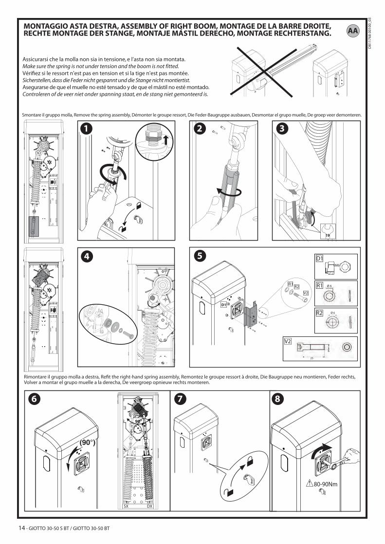
Assicurarsi che la molla non sia in tensione, e l’asta non sia montata.
Make sure the spring is not under tension and the boom is not fitted.
Véri�ez si le ressort n'est pas en tension et si la tige n'est pas montée.
Sicherstellen, dass die Feder nicht gespannt und die Stange nicht montiertist.
Asegurarse de que el muelle no esté tensado y de que el mástil no esté montado.
Controleren of de veer niet onder spanning staat, en de stang niet gemonteerd is.
Smontare il gruppo molla, Remove the spring assembly, Démonter le groupe ressort, Die Feder-Baugruppe ausbauen, Desmontar el grupo muelle, De groep veer demonteren.
AA
Volver a montar el grupo muelle a la derecha, De veergroep opnieuw rechts monteren.
1
6 7 8
2 3
4
17
5
R1R2
V2
D1
V2
25
6
D1
R2
Ø 6R1
Ø 6
M6
14 - GIOTTO 30-50 S BT / GIOTTO 30-50 BT
D8
11
76
8 0
01
00
_0
3

Montaggio lampeggiante, Assembling the �ashing light, Montage du clignotant, Montage Blinkleuchte, Montaje luz intermitente, Montage knipperlicht. AC
AD
"A"
CELLULA130
"B"
GTO 130
Fare riferimento al manuale Cellula 130,Refer to PHOTOCELL 130 manual,Consultez le Manuel CELLULA 130,Auf das Handbuch CELLULA 130 Bezug nehmen,Consultar el manual CELLULA 130,Het handboek CELLULA 130 raadplegen.
"A"
CELLULA130
Montaggio Fotocellula Cellula 130 / GTO 130, Assembling Photocell 130/GTO 130, Montage Photocellule Cellula 130 /
GTO 130, Montage Fotozelle Cellula 130 / GTO 130, Montaje Fotocélula Cellula 130 / GTO 130, Montage Fotocel
Cellula 130 / GTO 130.
Per montaggio colonnine-fare riferimento al
manuale GTO 130,
Refer to GTO 130 manual for assembly of stations,Pour monter les colonnes consultez le manuel
GTO130,Für die Montage der Säulen
auf das Handbuch GTO 130 Bezug nehmen,Para montar las columnas
consultar el manual GTO 130,Voor montage kolommen
het handboek GTO 130 raadplegen.
V1
V2
2
1
2
1
32
4,8
13,5
3,9
25
3,9
V3
5
4
3
V2
V1
V3
4
2
3
V1
V2
GIOTTO 30-50 S BT / GIOTTO 30-50 BT - 15
D8
11
76
8 0
01
00
_0
3

AE
AF
CO
MS
TAR
TS
TOP
PH
OT
BA
R1
OP
EN
CLO
SE
FAU
LT P
HO
T
CO
M
BA
R2
M1 M2
24
V ~
(+
)
0V
~ (
-)
Vsa
fe ~
(+
)
Vsa
fe ~
(-)
24
V ~
(+
)
0V
~ (
-)
L N L N
16 - GIOTTO 30-50 S BT / GIOTTO 30-50 BT
D8
11
76
8 0
01
00
_0
3

ACCESS TO MENUS Fig. 1
para . 1
para . 2
para . . . .
logic. 1logic
logic. 2
logic. . . .
ITA
FRA
DEU
ENG
esp
OK
OK
OK
OK
OK
- +
- +
- +
- +
add. start hidden button release ok 01desired button
PRG.erase 64
COD RX 1A9C OK 22FD OK 01 OK
+/-
See PARAMETERS MENU
See LOGIC MENU
radio
language
PRGdefault
v
Exit Menù
Confirm/Switch on display
Scroll up
Scroll down
x 2
- +
- +
OK OKstat vers . . .
+/-
OK 0000
+/-
+/-
n. cycles
OK 00n. Re otes
DIAGNOSTICS and WARNINGS
DIAGNOSTICS CODE DESCRIPTION NOTES
stre START input activated
stop STOP input activated
phot attivazione ingresso PHOT
bar SAFETY EDGE input activated
bar2SAFETY EDGE input activated on slave motor (opposite leaves connection)
cls CLOSE input activated
open OPEN input activated
ti e TIMER input activated
svo opening limit switch input activated
svc closing limit switch input activated
refo enabling input reference opening
refc enabling input reference closing
Er01 photocell test errorcheck photocell connection and/or logic settings
Er1x* board hardware test error check connections to motor
er2x* Encoder Errormotor or signal encoder power leads inver-ted/disconnected
er3x* reverse due to obstacle check for obstacles in path
Er4x* thermal cutout error Allow motor to cool
Er5x* anomaly in communication whit remote devices check Scs1 serial connections
er61 running of battery
Erfx* limit switch error check limit switch connections
* X = 0,1,…,9,A,B,C,D,E,F
35.40 Set torque threshold Maximum instantaneous motor torque
ENG
LISH
GIOTTO 30-50 S BT / GIOTTO 30-50 BT - 23
D8
11
76
8 0
01
00
_0
3
INSTALLER WARNINGS
Anything that is not explicitly provided for in the installation ma-nual is not allowed. The operator’s proper operation can only be guaranteed if the information given is complied with. The Firm shall not be answerable for damage caused by failure to comply with the instructions featured herein.While we will not alter the product’s essential features, the Firm re-serves the right, at any time, to make those changes deemed oppor-tune to improve the product from a technical, design or commercial point of view, and will not be required to update this publication accordingly.
WARNING! Important safety instructions. Carefully read and comply with all the warnings and instructions that come with the product as incorrect installation can cause injury to people and animals and damage to property. The warnings and instructions give important information regarding safety, installation, use and maintenance. Keep hold of instructions so that you can attach them to the technical ile and keep them handy for future reference.
GENERAL SAFETYThis product has been designed and built solely for the purpose indicated herein. Uses other than those indicated herein might cause damage to the product and create a hazard.- The units making up the machine and its installation must meet the requirements of the following European Directives, where applicable: 2004/108/EC, 2006/95/EC, 2006/42/EC, 89/106/EC, 99/05/EC and later amendments. For all countries outside the EEC, it is advisable to comply with the standards mentioned, in ad-dition to any national standards in force, to achieve a good level of safety.
- The Manufacturer of this product (hereinafter referred to as the “Firm”) disclaims all responsibility resulting from improper use or any use other than that for which the product has been designed, as indicated herein, as well as for failure to apply Good Practice in the construction of entry systems (doors, gates, etc.) and for deformation that could occur during use.
- Before installing the product, make all structural changes required to produce safety gaps and to provide protection from or isolate all crushing, shearing and dragging hazard areas and danger zones in general in accordance with the provisions of standards EN 12604 and 12453 or any local installation standards. Check that the existing structure meets the necessary strength and stability requirements.
- Before commencing installation, check the product for damage.- The Firm is not responsible for failure to apply Good Practice in the construction and maintenance of the doors, gates, etc. to be motorized, or for deformation that might occur during use.
- Make sure the stated temperature range is compatible with the site in which the automated system is due to be installed.
- Do not install this product in an explosive atmosphere: the presence of lammable fumes or gas constitutes a serious safety hazard.
- Disconnect the electricity supply before performing any work on the system. Also disconnect bufer batteries, if any are connected.
- Before connecting the power supply, make sure the product’s ratings match the mains ratings and that a suitable residual current circuit breaker and overcurrent protection device have been installed upline from the electrical system. Have the automated system’s mains power supply itted with a switch or omnipolar thermal-magnetic circuit breaker with a contact separation that meets code requirements.
- Make sure that upline from the mains power supply there is a residual current circuit breaker that trips at no more than 0.03A as well as any other equipment required by code.
- Make sure the earth system has been installed correctly: earth all the metal parts belonging to the entry system (doors, gates, etc.) and all parts of the system featuring an earth terminal.
- Installation must be carried out using safety devices and controls that meet standards EN 12978 and EN 12453.
- Impact forces can be reduced by using deformable edges.- In the event impact forces exceed the values laid down by the relevant standards, apply electro-sensitive or pressure-sensitive devices.
- Apply all safety devices (photocells, safety edges, etc.) required to keep the area free of impact, crushing, dragging and shearing hazards. Bear in mind the standards and directives in force, Good Practice criteria, intended use, the instal-lation environment, the operating logic of the system and forces generated by the automated system.
- Apply all signs required by current code to identify hazardous areas (residual risks). All installations must be visibly identiied in compliance with the provisions of standard EN 13241-1.
- Once installation is complete, apply a nameplate featuring the door/gate’s data.- This product cannot be installed on leaves incorporating doors (unless the motor can be activated only when the door is closed).
- If the automated system is installed at a height of less than 2.5 m or is accessible, the electrical and mechanical parts must be suitably protected.
- Install any ixed controls in a position where they will not cause a hazard, away from moving parts. More speciically, hold-to-run controls must be positioned within direct sight of the part being controlled and, unless they are key operated, must be installed at a height of at least 1.5 m and in a place where they cannot be reached by the public.
- Apply at least one warning light (lashing light) in a visible position, and also attach a Warning sign to the structure.
- Attach a label near the operating device, in a permanent fashion, with informa-tion on how to operate the automated system’s manual release.
- Make sure that, during operation, mechanical risks are avoided or relevant protective measures taken and, more speciically, that nothing can be banged, crushed, caught or cut between the part being operated and surrounding parts.
- Once installation is complete, make sure the motor automation settings are correct and that the safety and release systems are working properly.
- Only use original spare parts for any maintenance or repair work. The Firm dis-claims all responsibility for the correct operation and safety of the automated system if parts from other manufacturers are used.
- Do not make any modiications to the automated system’s components unless explicitly authorized by the Firm.
- Instruct the system’s user on what residual risks may be encountered, on the control systems that have been applied and on how to open the system manu-ally in an emergency. give the user guide to the end user.
- Dispose of packaging materials (plastic, cardboard, polystyrene, etc.) in accord-ance with the provisions of the laws in force. Keep nylon bags and polystyrene out of reach of children.
WIRINGWARNING! For connection to the mains power supply, use: a multicore cable with a cross-sectional area of at least 5x1.5mm2 or 4x1.5mm2 when dealing with three-phase power supplies or 3x1.5mm2 for single-phase supplies (by way of example, type H05 VV-F cable can be used with a cross-sectional area of 4x1.5mm2). To con-nect auxiliary equipment, use wires with a cross-sectional area of at least 0.5 mm2.- Only use pushbuttons with a capacity of 10A-250V or more.- Wires must be secured with additional fastening near the terminals (for example,
using cable clamps) in order to keep live parts well separated from safety extra low voltage parts.
- During installation, the power cable must be stripped to allow the earth wire to be connected to the relevant terminal, while leaving the live wires as short as possible. The earth wire must be the last to be pulled taut in the event the cable’s fastening device comes loose.
WARNING! safety extra low voltage wires must be kept physically separate from low voltage wires.Only qualiied personnel (professional installer) should be allowed to access live parts.
CHECKING THE AUTOMATED SYSTEM AND MAINTENANCEBefore the automated system is inally put into operation, and during maintenance work, perform the following checks meticulously:- Make sure all components are fastened securely.- Check starting and stopping operations in the case of manual control.- Check the logic for normal or personalized operation.- For sliding gates only: check that the rack and pinion mesh correctly with 2 mm of play along the full length of the rack; keep the track the gate slides on clean and free of debris at all times.
- For sliding gates and doors only: make sure the gate’s running track is straight and horizontal and that the wheels are strong enough to take the weight of the gate.
- For cantilever sliding gates only: make sure there is no dipping or swinging during operation.
- For swing gates only: make sure the leaves’ axis of rotation is perfectly vertical.- Check that all safety devices (photocells, safety edges, etc.) are working properly and that the anti-crush safety device is set correctly, making sure that the force of impact measured at the points provided for by standard EN 12445 is lower than the value laid down by standard EN 12453.
- Impact forces can be reduced by using deformable edges.- Make sure that the emergency operation works, where this feature is provided.- Check opening and closing operations with the control devices applied.- Check that electrical connections and cabling are intact, making extra sure that insulating sheaths and cable glands are undamaged.
- While performing maintenance, clean the photocells’ optics.- When the automated system is out of service for any length of time, activate the emergency release (see “EMERGENCY OPERATION” section) so that the operated part is made idle, thus allowing the gate to be opened and closed manually.
- If the power cord is damaged, it must be replaced by the manufacturer or their technical assistance department or other such qualiied person to avoid any risk .
- If “D” type devices are installed (as deined by EN12453), connect in unveriied mode, foresee mandatory maintenance at least every six months
WARNING! Remember that the drive is designed to make the gate/door easier to use and will not solve problems as a result of defective or poorly performed installation or lack of maintenance
SCRAPPINGMaterials must be disposed of in accordance with the regulations in force. There are no particular hazards or risks involved in scrapping the automated system. For the purpose of recycling, it is best to separate dismantled parts into like materials (electrical parts - copper - aluminium - plastic - etc.).
DISMANTLINGIf the automated system is being dismantled in order to be reassembled at another site, you are required to:- Cut of the power and disconnect the whole electrical system.- Remove the actuator from the base it is mounted on.- Remove all the installation’s components.- See to the replacement of any components that cannot be removed or happen to be damaged.
AVVERTENZE PER L’INSTALLATORE D811766_0624 - GIOTTO 30-50 S BT / GIOTTO 30-50 BT
D8
11
76
8 0
01
00
_0
3

INSTALLATION MANUAL
2) GENERAL OUTLINECompact electromechanical barrier suitable for limiting private areas, parkings, access areas for vehicles only. Available for passageways from 3 to 5 metres. Adjustable electronic limit switches, they guarantee correct boom stopping position.The emergency release device for manual manoeuvre is controlled by a personalised key lock.The actuator is always supplied for left-hand side itting. However, when necessary, the opening direction can be reversed by means of simple operations.The CBO mod. foundation base (on request) makes barrier installation easier.Appropriate ittings make it easy to install accessories.The LIBRA-C-G/LIBRA-C-GS control panel is supplied by the manufac-turer with standard setting. Any change must be set by means of the incorporated display or by means of the universal programmer.
3) TECHNICAL SPECIFICATIONS
MOTOR
Power supply 230V±10% 50Hz(*)
Power absorbed300W (GIOTTO S BT 30/ GIOTTO S BT 50)
250W (GIOTTO BT 30/GIOTTO BT 50)
Internal lubrication permanent grease
Max torque
280 Nm (GIOTTO S BT 30)
380 Nm (GIOTTO S BT 50)
250 Nm (GIOTTO BT 30)
350 Nm (GIOTTO BT 50)
Opening time
2,5s (GIOTTO S BT 30)
4s (GIOTTO S BT 50 / (GIOTTO BT 30)
5s (GIOTTO BT 50)
Boom length
3 m (GIOTTO S BT 30/ GIOTTO BT 30)
5 m (GIOTTO S BT 50/ GIOTTO BT 50)
6 m [(GIOTTO BT 50/ GIOTTO S BT 50) + ATG6]
Manual mechanical release customised key
Type of boom rectangular
Limit deviceselectrical incorporated and electroni-cally adjustable
Type of useintensive (GIOTTO S BT 30/ GIOTTO S BT 50)
semi intensive (GIOTTO BT 30/ GIOTTO BT 50)
Working temperature from -20°C to +55°C
Degree of protection IP 54
Operator weight (without boom)
41 Kg (GIOTTO S BT 30 / (GIOTTO BT 50)
42 Kg (GIOTTO S BT 50)
40 Kg (GIOTTO BT 30)
Dimensions see ig. A
CONTROL UNIT
Mains/low voltage insulation > 2MOhm 500V
Dielectric strength mains/low voltage 3750V~ for 1 minute
Supply to accessories 24V~ (180 mA max absorption)
Barrie-open warning light 24V~ 3W max
Blinker 24V~ 25W max
Fuses see Fig. G
N° of combinations 4 billion
Built-in Rolling-Code radio-receiver frequency 433.92MHz
Max. n° of remotes that can be memorized 63
Setting of parameters and op-tions
Universal handheld programmer/LCD display
(*)= special power supply voltages on request.
Usable transmitter versions:All ROLLING CODE transmitters compatible with:
4.1) FOUNDATION PLATE (Fig. B1).4.2) FASTENING ANCHOR BOLTS (Fig. B2).
5) FITTING OF THE ACTUATORWARNING! The barrier must be exclusively used for vehicles to drive through. Pedestrians must not walk within the operator
manoeuvring area. An appropriate pedestrian passageway must be provided for.The passageway must be suitably indicated by means of the warn-ing signs illustrated in Fig.A.WARNING: before opening the door, the spring must be unloaded
(vertical boom). The door of the box must be facing towards the inside of the property. When you stand in the middle of the passageway, facing outwards, if the box is on your left, the barrier is left-hand itted, if the box is on your right, the barrier is right-hand itted. The actuator is always supplied for left-hand side itting.
6) Left-hand itting (Fig. A, B, C, D).
7) Right-hand itting (Fig. AA)- Carry out bar balancing.- Set the Direction Reversal logic to ON in the control panel.
Warning: the Direction Reversal logic must be conigured to OFF for left-hand itted barriers, and to ON for right-hand itted
barriers. Otherwise, the limit devices will not operate or an encoder direction error will be displayed.
8) BAR BALANCING (Fig. F).
9) OPTIONAL ACCESSORIES (Fig.E)- Foundation base CBO - Photocell 130 fastening post kit KIT GTO 130 - Fixed end rest for boom FAF- Folding leg to support boom GA- Cushioned folding leg to support boom GAMA- Skirt ready assembled on boom SB- Safety edge BIR- Lights kit for booms between 3m and 4.5m long KIT GTO LIGHT 3- Lights kit for booms 5m or 6m long KIT GTO LIGHT 5- Top or bottom boom covering proile PCA- ELL ART Articulated Boom- KIT BAT- RMM- THERMO- GTO ATG-GTO AQG- ATG 3-ATG 5 -ATG 6- AQG 3-AQG 5
10) Accessories: boom length limits and balancing (Fig. E1).For further information about the installation and use of accessories, refer to the respective instruction manuals.
11) Assembling the lashing light RADIUS B LTA24R1/ RADIUS B LTA24R2. (FIG. AC)- Complete assembly and wiring as directed in instructions provided
for RADIUS B LTA24R1/ RADIUS B LTA24R2.
12) Assembling Photocell 130 / GTO 130 (FIG. AD).
----------------------------------------------------------
13) ELECTRICAL INSTALLATION SET-UPWARNING: before opening the door, the spring must be unloaded (vertical boom). Set up the electrical installation (ig. A) with reference to the current regulations for electrical installations. Keep the mains power supply con-nections deinitely separate from the service connections (photocells, electric edges, control devices etc.). Fig. A shows the number of connections and section for a 100m length of power supply cables; for greater lengths, calculate the section for the true automation load. When the auxiliary connections exceed 50 metre lengths or go through critical disturbance areas, it is recommended to decouple the control and safety devices by means of suitable relays. The main automation components are (ig. A):I) Type-approved adequately rated omnipolar circuit-breaker with
at least 3,5 mm contact opening, provided with protection against overloads and short circuits, suitable for cutting out automation from the mains. Place, if not al ready installed, a type-approved difer-ential switch with a 0.03A threshold just before the automation system.
QR) Control panel and incorporated receiver.S) Key selector.AL) Blinker M) Actuators.A) Bar.F) Rest fork.CS) Electric edge.Ft,Fr) Pair of photocells.CF) Photocell post.T) 1-2-4 channel transmitter.RMM) Inductive metal mass detector (Fig. C1).LOOP) Mass detector loops.
14) CONNECTION (Fig. G)Once suitable electric cables have been run through the raceways and the automated device’s various components have been fastened at the predetermined points, the next step is to connect them as directed and illustrated in the diagrams contained in the relevant instruction manuals. Connect the live, neutral and earth wire (compulsory). The mains cable must be clamped in the relevant cable gland, and the accessories’ wires in the cable gland, while the earth wire with the yellow/green-coloured
GIOTTO 30-50 S BT / GIOTTO 30-50 BT - 25
D8
11
76
8 0
01
00
_0
3

sheath must be connected in the relevant terminal. WARNING: The electrical connections must be carried out workmanlike by qualiied experienced personnel, in conformity with all the current standards and with the use of appropriate materials. Lay out the electrical installation with reference to the current electrical standards. Keep the mains supply connections clearly separated from the service connections. In the initial section of the electrical installation, it a circuit breaker with a contact opening distance equal to or greater than 3,5 mm, provided with magnetothermal protection and a diferential switch having ad-equate capacity for the appliance consumption. For the wiring, only use cables conforming to the harmonised or national standards, having a cross section corresponding to the initial protection, the appliance consumption and the installation conditions, for example a 3x1.5 sq mm (H 05 VV-F) cable.
TERMINAL DESCRIPTION
1-2 Control for cooling fan 230V~ ±10% (1=L) (2=N)
3-4 Not used
6-7 Motor connections
15-5 Motor connections, closing reference
15-8 Motor connections, opening reference
9-10 Flashing light (24 V~, 25W)
11-12
Accessories power supply:24 V operation with mains power on.24 V (11+,12-) operation with no mains power and optional bufer battery kit.
13-14
Safety device power supply output (photocell transmitter). N.B.: output active only during operating cycle. 24 V Vsafe operation with mains power on.24 V (13+,14-) Vsafe operation with no mains power and optional bufer battery kit.
15-16START button (N.O.)This option can be set via the “logic menu”.Start - operation according to 2-3-4 step logic.
15-17STOP input (N.C.)The command stops movement.If not used, leave jumper inserted.
15-18PHOTOCELL input (N.C.).Operation according to photocell during opening logic.If not used, leave jumper inserted.
19 Safety device test input FAULT - PHOT (N.O.).
15-20
SAFETY EDGE input BAR (N.C.).The command reverses movement during closing and stops movement during opening.If not used, leave jumper inserted.
21-22Barrier-open warning light output (N.O. contact, 24V~/ 3W max) or, in alternative, alarm output (see Table “B”, Alarm SCA) and Connection To Parky Car-Park Management System
23-24-25-26 Encoder inputs
15-27
OPEN/ TIMER control button (N.O.)Open - Gate opened with this command.Timer - If the contact is closed, the leaves open and stay open until the contact is opened. If the contact connected is open, the leaves close and are ready for normal operation.
15-28 Close button CLOSE (N.O.)The command causes the leaf to close.
15) SAFETY DEVICES FIG. HNote: only use receiving safety devices with free changeover contact.
15.1) NON-TESTED DEVICES FIG. H1
15.2) TESTED DEVICES FIG. H2, H3
16) ADJUSTMENTS
RECOMMENDED ADJUSTMENT SEQUENCE:Adjusting the limit switches Fig.I (See reference section)Programming remote controls Setting of parameters/logic, where necessary
17) PARAMETERS MENU (para )(TABLE “A” PARAMETERS)
18) LOGIC MENU (logic)
(TABLE “B” LOGIC)
19) RADIO MENU (RADIO)
Logic Description
add startAdd Start Keyassociates the desired key with the Start command
erase 64
Erase ListWARNING! Erases all memorized remote controls from the receiver’s memory.
cod RX
Read receiver codeDisplays receiver code required for cloning remote con-trols.
v
ON = Enables remote programming of cards via a previously me-morized W LINK transmitter. It remains enabled for 3 minutes from the time the W LINK remote control is last pressed.
OFF=W LINK programming disabled.
- IMPORTANT NOTE: THE FIRST TRANSMITTER MEMORIZED MUST BE IDENTIFIED BY ATTACHING THE KEY LABEL (MASTER).
In the event of manual programming, the irst transmitter assigns the RECEIVER’S KEY CODE: this code is required to subsequently clone the radio transmitters.The Clonix built-in on-board receiver also has a number of important advanced features: • Cloningofmastertransmitter(rollingcodeorixedcode)• Cloningtoreplacetransmittersalreadyenteredinreceiver• Transmitterdatabasemanagement• ReceivercommunitymanagementTo use these advanced features, refer to the universal handheld pro-grammer’s instructions and to the CLONIX Programming Guide, which come with the universal handheld programmer device.
20) DEFAULT MENU (default)Restores the controller’s default factory settings.
21) LANGUAGE MENU (language)Used to set the programmer’s language on the display.
22) STATISTICS MENUShows:- board version- number of total manoeuvres made by the automation- number of remote controls saved to the built-in receiver
23) CONNECTION TO PARKY CAR-PARK MANAGEMENT SYSTEMThe board can be conigured in order to make an output available for controlling the barrier status. When the SCA Alarm logic is disabled (OFF) and the Alarm Time parameter is set to 0 s, the SCA contact (21-22) is conigured as follows (Fig. G):- contact closed between terminals 21-22 with the barrier lowered - contact open between terminals 21-22 with the barrier lifted 23.1) SERIAL CONNECTION USING SCS1 BOARD (Fig. AE) The LIBRA-C-G/LIBRA-C-GS control panel allows several automation units (SCS1) to be connected in a centralised way by means of appropri-ate serial inputs and outputs. This makes it possible to use one single command to open and close all the automation units connected.Following the diagram in Fig. AE, proceed to connecting all the LIBRA-C-G/LIBRA-C-GS control panels, exclusively using a telephone-type line. Should a telephone cable with more than one pair be needed, it is indispensable to use wires from the same pair.The length of the telephone cable between one appliance and the next must not exceed 250 m.At this point, each of the LIBRA-C-G/LIBRA-C-GS control panels must be appropriately conigured, by setting a MASTER unit irst of all, which will have control over all the others, to be necessarily set as SLAVE (see logic menu).Also set the Zone number (see parameter menu) between 0 and 127. The zone number allows you to create groups of automation units, each one answering to the Zone Master unit. Each zone can only be assigned one Master unit, the Master unit in zone 0 also controls the Slave units in the other zones. WARNING: the control panel set as the master must be the irst in the series.
23.2) Opposite Barriers (Fig. AF)By means of a serial connection, it is also possible to obtain centralised control of two opposite barriers/gates.In this case, the Master M1 control panel will simultaneously manage closing and opening for the Slave M2 control panel.SETTING REQUIRED FOR OPERATION:- MASTER board: zone=128, aster=ON- SLAVE board: zone=128, aster=OFFWIRING REQUIRED FOR OPERATION:- The MASTER and SLAVE control units are interconnected through the
INSTALLATION MANUAL
26 - GIOTTO 30-50 S BT / GIOTTO 30-50 BT
D8
11
76
8 0
01
00
_0
3
4 wires (RX/TX) for the SCS1 interface boards;- All the activation controls, as well as the remote controls must refer to
the MASTER board;- All the photocells must be connected to the MASTER control panel;- The safety edges of the MASTER leaf must be connected to the MASTER
control unit;- The safety edges of the SLAVE leaf must be connected to the SLAVE
control unit.
24) LIMIT SWITCH SETTINGWARNING: before opening the door, the spring must be unloaded (vertical boom). The barrier is provided with programmable electronic limit switches and mechanical stop devices. There must be a rotation margin (about 1°) on closing and opening between the electrical limit switches and mechanical stop devices (Fig. J). To evaluate correctly the values set, you are advised to carry out a few complete consecutive manoeuvres.
25) EMERGENCY RELEASE (Fig. Y)WARNING! When an actuator without bar needs to be released, ensure that the balancing spring is not compressed (bar in the opening posi-tion).26) MALFUNCTION: CAUSES and REMEDIES26.1) The bar does not open. The motor does not turn.WARNING: before opening the door, the spring must be unloaded
(vertical boom).1) Check that the photocells are not dirty, or engaged, or not aligned.
Proceed accordingly. Check the electric edge.2) Check the correct connection of the drive motor and capacitor.3) Check that the electronic appliance is correctly supplied. Check the
integrity of the fuses.4) Use the control unit self-diagnosis (see “Acces to Menus”), to check
whether the functions are correct. Identify any possible cause for the fault. If self-diagnosis indicates that a start command persists, check that there are no radio transmitters, start buttons or other control devices keeping the start contact activated (closed).
5) If the control unit does not work, it must be replaced.6) Check the activation of the reference microswitches by checking the
messages appearing on the control panel display. 7) Lubriicate the guide-ressort tirants in case of rumors or vibrations.
26.2) The bar does not open. The motor turns but there is no move-ment.1) The manual release was left engaged. Reset the motorised opera-
tion.2) If the release is in the motorised operation position, check the gearmo-
tor for integrity.
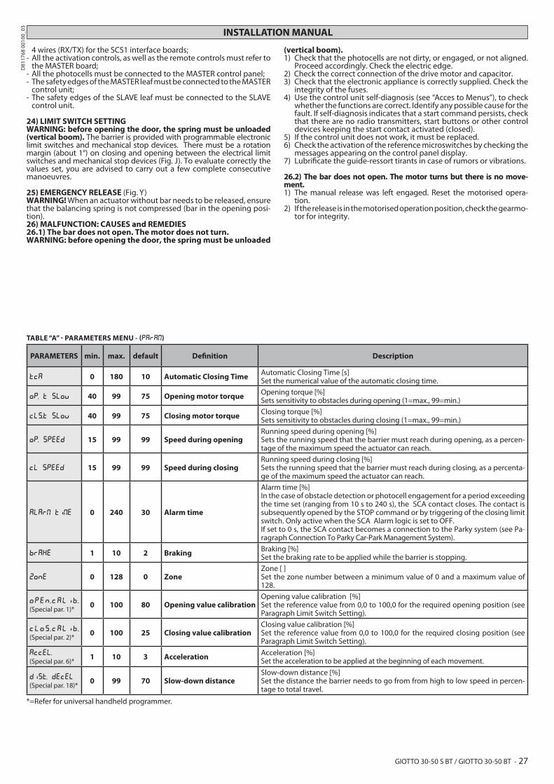
TABLE “A” - PARAMETERS MENU - (PARA )
PARAMETERS min. max. default Deinition Description
tca 0 180 10 Automatic Closing Time Automatic Closing Time [s]Set the numerical value of the automatic closing time.
op. t slov 40 99 75 Opening motor torque Opening torque [%]Sets sensitivity to obstacles during opening (1=max., 99=min.)
cls.t slov 40 99 75 Closing motor torque Closing torque [%]Sets sensitivity to obstacles during closing (1=max., 99=min.)
Op. speed 15 99 99 Speed during openingRunning speed during opening [%]Sets the running speed that the barrier must reach during opening, as a percen-tage of the maximum speed the actuator can reach.
cl speed 15 99 99 Speed during closingRunning speed during closing [%]Sets the running speed that the barrier must reach during closing, as a percenta-ge of the maximum speed the actuator can reach.
alar ti e 0 240 30 Alarm time
Alarm time [%]In the case of obstacle detection or photocell engagement for a period exceeding the time set (ranging from 10 s to 240 s), the SCA contact closes. The contact is subsequently opened by the STOP command or by triggering of the closing limit switch. Only active when the SCA Alarm logic is set to OFF.If set to 0 s, the SCA contact becomes a connection to the Parky system (see Pa-ragraph Connection To Parky Car-Park Management System).
brake 1 10 2 Braking Braking [%]Set the braking rate to be applied while the barrier is stopping.
Zone 0 128 0 ZoneZone [ ]Set the zone number between a minimum value of 0 and a maximum value of 128.
open .calib .
(Special par. 1)*0 100 80 Opening value calibration
Opening value calibration [%]Set the reference value from 0,0 to 100,0 for the required opening position (see Paragraph Limit Switch Setting).
clos .calib .
(Special par. 2)*0 100 25 Closing value calibration
Closing value calibration [%]Set the reference value from 0,0 to 100,0 for the required closing position (see Paragraph Limit Switch Setting).
accel.
(Special par. 6)*1 10 3 Acceleration Acceleration [%]
Set the acceleration to be applied at the beginning of each movement.
dist. decel
(Special par. 18)*0 99 70 Slow-down distance
Slow-down distance [%]Set the distance the barrier needs to go from from high to low speed in percen-tage to total travel.
*=Refer for universal handheld programmer.
INSTALLATION MANUAL
GIOTTO 30-50 S BT / GIOTTO 30-50 BT - 27
D8
11
76
8 0
01
00
_0
3

INSTALLATION MANUAL
TABLE B: LOGIC MENU (logic)
Logic Default Deinition
Cross out
setting used
Description
TCA ON AutomaticClosing Time
ON Switches automatic closing on.
OFF Switches automatic closing of.
Ibl open ON Block PulsesON The start pulse has no efect during opening.
OFF The start pulse has efect during opening or closing.
ibl TCA OFF Impulse lock TCAON The Start impulse has no efect during the TCA dwell period.
OFF The Start impulse becomes efective during the TCA dwell period.
2 step OFF 2 stepON
Enables the 2-step logic (prevails over the “3-step logic”).
Response to the START impulse
Barrier 2 steps 3 steps 4 steps
closedopens opens
opens
on closing stop
opencloses
closes closes
on opening stop + TCA stop + TCA
after stop opens opens opens
OFFDisables the 2-step logic, activating the 4-step logic if the “3-step logic” is OFF.
3 step ON 3 step
ONEnables the 3-step logic (if the “2-step logic” is OFF).
OFF
Disables the 3-s6tep logic, activating the 4-step logic if the “2-step logic” is OFF.
preal OFF Pre-alarmON The lashing light comes on approx. 3 seconds before the motors start.
OFF The lashing light comes on at the same time as the motors start.
hold to
RunOFF Deadman
ONHold-to-run operation: the manoeuvre continues as long as the OPEN and CLOSE control keys are kept pressed. The radio transmitter cannot be used.
OFF Normal impulse operation.
Photoc.open ON Photocellsduring opening
ONWhen beam is broken, operation of the photocell is switched of during opening. During closing, movement is reversed immediately.
OFFWhen beam is broken, photocells are active during both opening and closing. When beam is broken during closing, movement is reversed only once the photocell is cleared.
fast cls OFF Rapid closingON
Closes barrier after photocell disengagement, before waiting for the end of the TCA (automatic closing time) set.
OFF Command not entered.
test phot OFF Photocell test
ON Switches photocell testing on
OFFSwitches photocell testing ofIf disabled (OFF), it inhibits the photocell testing function, enabling connection of devices not equipped with supplementary test contacts.
ster OFF Master/slaveON Control panel is set up as the Master unit in a centralized serial connection system.
OFF Control panel is set up as a Slave unit in a centralized serial connection system.
fixed code OFF Fixed codeON Receiver is conigured for operation in ixed-code mode.
OFF Receiver is conigured for operation in rolling-code mode.
radio prog ON Remote control programming
ON
Enables wireless memorizing of transmitters: 1- Press in sequence the hidden key (P1) and normal key (T1-T2-T3-T4) of a transmitter that has already been memorized in standard mode via the radio menu.2- Press within 10 secs. the hidden key (P1) and normal key (T1-T2-T3-T4) of a transmitter to be memorized.The receiver exits programming mode after 10 secs.: you can use this time to enter other new transmitters. This mode does not require access to the control panel.IMPORTANT: Enables the automatic addition of new transmitters, clones and replays.
OFFDisables wireless memorizing of transmitters. Transmitters are memorized only using the relevant Radio menu.IMPORTANT: Disables the automatic addition of new transmitters, clones and replays.
alar sca ON SCA AlarmON
The SCA contact (terminals 21-22) behaves as follows:- with barrier open and on opening: contact closed (warning light on)- with barrier closed:contact open: (warning light of)- on closing: intermittent contact (blinking)
OFF The SCA contact closes according to the modes set by the Alarm Time parameter.
change ot. OFF Reversing motionON Change this parameter if the opening direction needs to be changed
OFF Standard operating mode.
open-ti er
(special dip 2*)OFF TIMER su OPEN
ON Input between terminals 15-27 works as TIMER.
OFF Input between terminals 15-27 works as OPEN.
*=Refer for universal handheld programmer.
28 - GIOTTO 30-50 S BT / GIOTTO 30-50 BT
D8
11
76
8 0
01
00
_0
3

MANUALE D’USO: MANOVRA MANUALE - USER’S MANUAL: MANUAL OPERATION- MANUEL D’UTILISATION: MANŒUVRE MANUELLE - BEDIENUNGSANLEITUNG: MANUELLES MANÖVER-MANUAL DE USO: ACCIONAMIENTO MANUAL - GEBRUIKSHANDLEIDING: MANUEEL MANOEUVRE
Fig. Y
GIOTTO 30-50 S BT / GIOTTO 30-50 BT - 53
D8
11
76
8 0
01
00
_0
3