gigabit ethernet design ece164.02 - spring 2004 group 1 presentation 5 – yashar pirzadeh
TRANSCRIPT
GIGABIT ETHERNET DESIGNECE164.02 - Spring 2004
Group 1
Presentation 5 – Yashar Pirzadeh
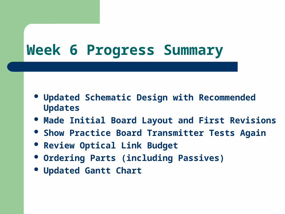
Week 6 Progress Summary
Updated Schematic Design with Recommended Updates
Made Initial Board Layout and First Revisions Show Practice Board Transmitter Tests Again Review Optical Link Budget Ordering Parts (including Passives) Updated Gantt Chart

Gantt Chart

Practice Board
Transmitter Receiver

Transmitter Assembly (cont.)
Back of Board (scraping to eliminate bad grounds)

Transmitter Testing
10 dB Attenuation – BER = 0E-9 for 30 seconds

Transmitter Testing
10 dB Attenuation – BER = 10E-9 for 30 seconds

Transmitter Testing
Failure = 50 dB, BER= 10E-7 for 30 seconds
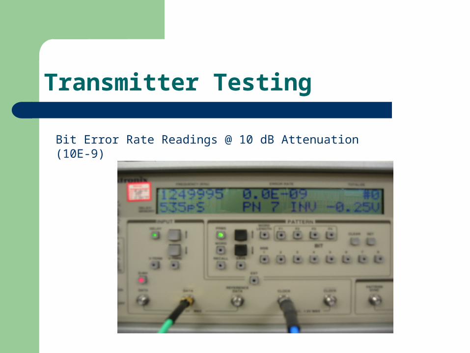
Transmitter Testing
Bit Error Rate Readings @ 10 dB Attenuation (10E-9)

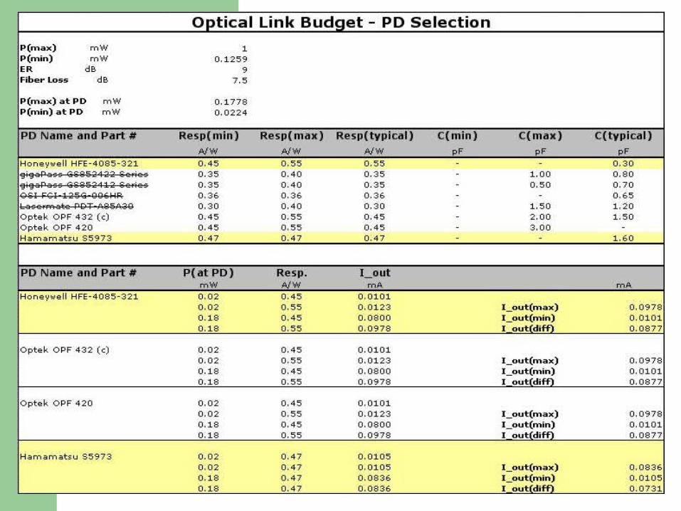
Optical Link Budget
Decided on Hamamatsu PD – $18-20 for 1-99 quantity– $6.50 for 10,000+ quantity
No luck with VCSEL Passives ordered within next forty-eight
hours via credit card to be reimbursed– Budget for these calculated and presented next
week
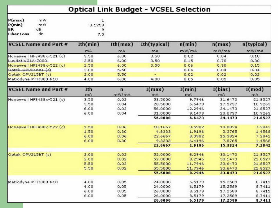
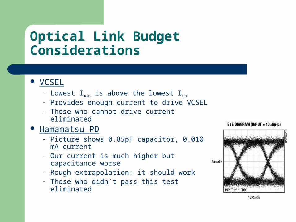
Optical Link Budget Considerations
VCSEL– Lowest Imin is above the lowest Ith
– Provides enough current to drive VCSEL– Those who cannot drive current eliminated
Hamamatsu PD– Picture shows 0.85pF capacitor, 0.010 mA
current– Our current is much higher but capacitance
worse– Rough extrapolation: it should work– Those who didn’t pass this test eliminated
Review of Schematic Changes
Minimal: Removed RC Circuit from Receiver
Important Considerations:– Tight loops, filters, and power supply location
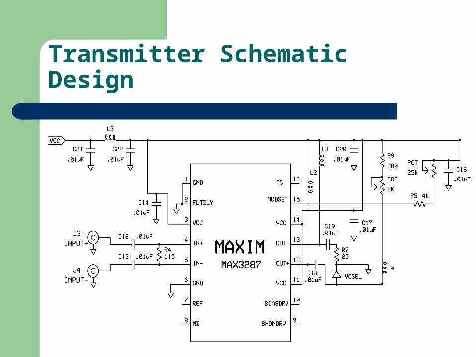
Transmitter Schematic Design
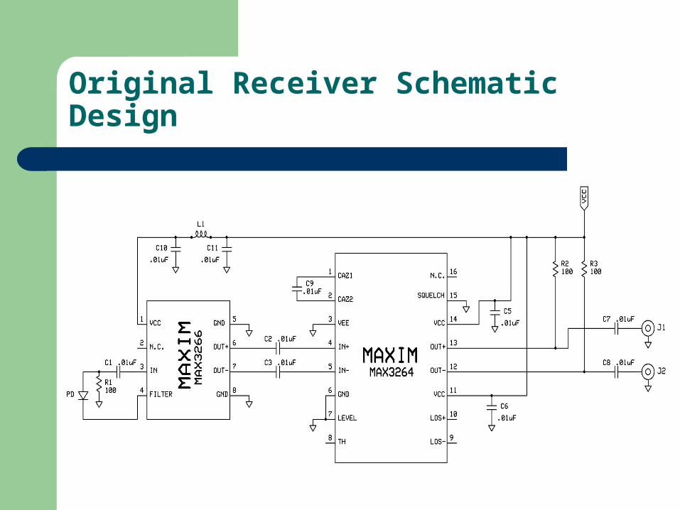
Original Receiver Schematic Design

Revised Receiver Schematic Design

Review of Board Layout Changes
Overall– More overall symmetry– 45 degree angles for wires, no reflection of high
frequency signals Transmitter
– VCSEL straight angle into 3287 through capacitor– Problem: Capacitor about 2mm, only 4 mm space
before transmission line issues– Missing portions from Tx schematic included

Board Layout Revisions (contd.)
Receiver:– Curve the shield around receiver, ground it– Keep power away from high frequency signals
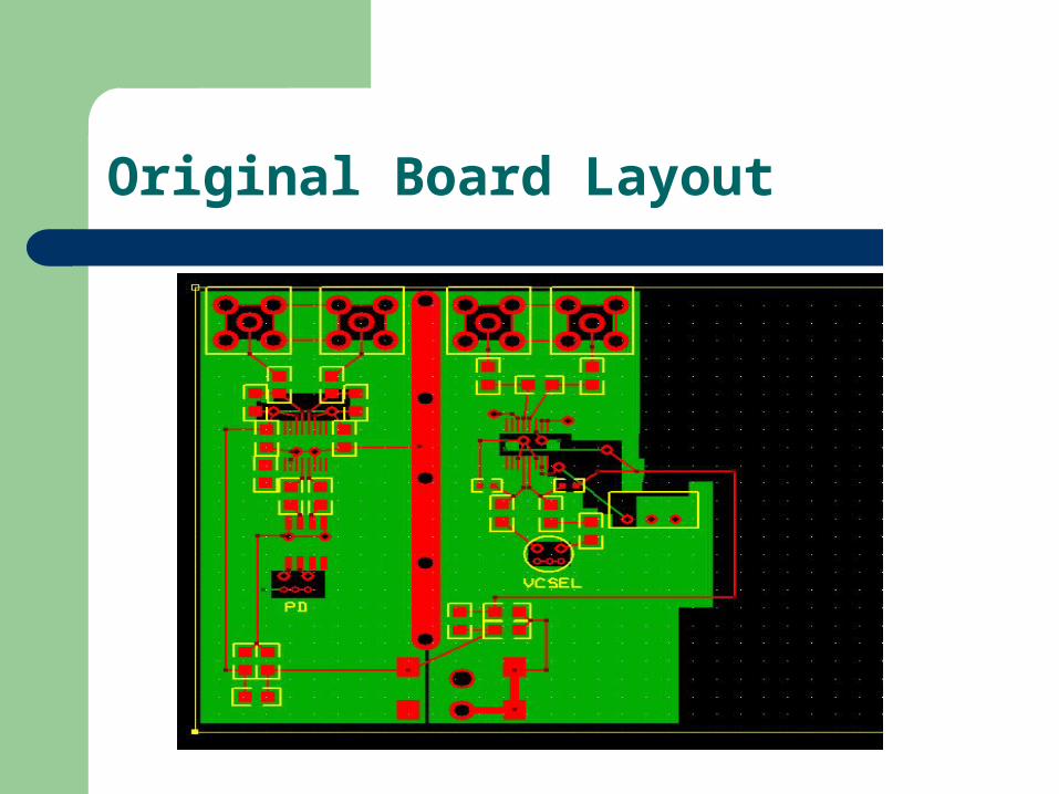
Original Board Layout
Revised Board Layout
Next Week’s Agenda (and beyond)
Spring Break Hopefully board is available Begin building board with
available parts Nag vendors whose parts are
missing Formal Budget Update Gantt Chart

THE END
Group Members– Russell Cook– Yashar Pirzadeh– James Dezelle