gi41-1 integrate infrastructure management and … gi41-1 integrate infrastructure management and...
TRANSCRIPT

1
GI41-1Integrate Infrastructure Management and Engineering Design with Autodesk® GIS Design Server
Steve Kerr – KEMA, Inc.Geoff Zeiss – Autodesk, Inc.
Course NR

2
Presentation Outline
Autodesk Enterprise GIS StrategyProcess Unification• Vision• Examples• How to get there
Case Study: Migration from MAP tiles to AGDS• Business Drivers• Approach• Data migration and application configuration• Next phase• Future possibilities
Conclusions
Autodesk’s Unique Value
Installed base• 1.3 million surveyors, land planners, and
engineers
The complete lifecycle• Surveying, design, analysis, construction
documentation and management, operations, maintenance
Maintain information throughout lifecycle• Engineering accuracy and precision• Input once, reuse repeatedly
Open infrastructure data server• Oracle10g Spatial
Industry standards• OGC • LandXML • J2EE• Competitive data formats
DraftingSurveying
Construction
Planning & Analysis
Infrastructure LifecycleManagement
Managing &
Operating
Mapping &Design
Survey Map Design Construct Operate
Information Loss
Information Maintained

3
GIS Dept
Mapping
Operations Dept
Outage
Maintenance Dept
Work Order
Customer Service
Billing
EngineeringOr CAD Dept
Design & Drafting
Land base
Survey
AGDSOracle 9i/10g
Autodesk MapAutodesk MapAutodesk MapGuide
Autodesk Survey
Autodesk MapGuide Autodesk Volo View
Creating Operating Efficiencies
Business DriversReduce costs
• Efficiency through data sharing• Field force automation• Unify business processes• Efficiency through back-office integration
Improve quality of service• Improved data quality and timeliness
• Deliver quality data to the field• Improve customer responsiveness
Support rapid provisioning of new services• Rapid development and deployment of new application
supporting new services• Ex. Wireless, PDA/GPS for pole inventory, applications
for customer services

4
Process Unification: the Vision
The VISION: • Data sharing between applications is the key to
streamlined business processes
Rule:• Have the business process drive the choice of
technology, not the reverse
Process Unification: Benefits
Eliminate Redundant Data:• Reduce cost and confusion of systems maintaining duplicate
dataStreamline Processes:• Remove many manual steps from each business process
Improved Quality of Service:• Data more accurate, due in part to reduced posting time
Better Decision Making:• Comprehensive view of data facilitates better decision making

5
Typical System Architecture
G ISRDBM S
O utageM gm t
ElectricalAnalysis
T ransform erM anager
W orkflowM anager
Landbase
Im port
Export
INTRANETCustom
M apViewer
DG N
Plotter
C ircuitD iagram s
DG N
ConstructionDrawings
D G NPaper
FIELDCustom
M apViewer
DG N
CircuitD iagram s
(M icrostation)
Consultant(AutoC AD )
ConstructionDrawings
(M icrostation)
FM E
DW G
G ISData Entry
Paper
W FM Data
EA Data
O M Data
TM D ata
DG ND G N
Engineering Design
EAI
ERP
AutodeskAGDS
MAP / AUD
AutodeskExpress Viewer
Process Unification Example: GIS, GWD, Field
GIS
GWD
WorkManagement
MaterialsManagement
MobileUnits

6
Process Unification Example: Inspection jobs
Work Management
GIS
Valve InspectionLeak Survey
Laying the groundwork
1. Move to Enterprise GIS• Seamless database• Model location, attributes, connections, associations
2. Enable Architecture for sharing• Applications must be able to share data and
communicate in general

7
Move from CAD based GIS to Enterprise GIS
MAP
EnterpriseData
(AGDS)
MAP
(AGDS)
Integration to other Enterprise Applications
Data Migration
Architecture Options
Three options for architecture: 1. Point to point
• Custom interfaces2. Enterprise Application Integration (EAI)
• E.g. WebLogic, WebSphere MQ3. Hybrid
• EAI, COM, Oracle triggers

8
Architecture – Point to Point
GIS
CIS OMS
One-Call
WorkManagement
EngineeringAnalysis
Architecture – EAI approach
Property Records
ERP Back Office Suite
CISAssetManagement
Network Analysis
MWMWMS
Messaging System
GIS &GWD
OneCall
9
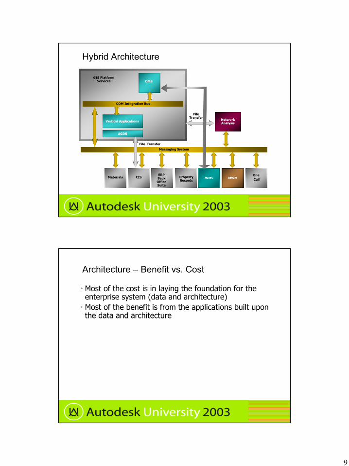
Hybrid Architecture
GIS Platform Services
Property Records
ERP Back Office Suite
CISMaterials
Network Analysis
OneCallMWMWMS
File Transfer
Messaging System
COM Integration Bus
Vertical Applications
AGDS
OMS
File Transfer
Architecture – Benefit vs. Cost
Most of the cost is in laying the foundation for the enterprise system (data and architecture)Most of the benefit is from the applications built upon the data and architecture

10
Creating the Foundation – Benefit vs. Cost
Foundation: Strong, but some improvements neededData: Not consolidated in GISApplications: Not fully developed. Need data to maximize value
Building a Facility Management System(Current Status)
Job Design
Work Management
Compliance Management
Applications
Data
Foundation
CartographicControl
Land Features
Other Facilities
Gas CarryingFacilities
Data Relationships &
Connectivity
Facility DataMaintenance
Tools Facility Data Model Land Data Model
Land DataMaintenance
Tools
GIS Maintenance
Ad Hoc Analysis
Cos
tB
enef
itC
ost
Ben
efit
Cos
tB
enef
it
Business process modeling – a key to success
Reference Process Models (RPM)• RPM 1: Unplanned Outage• RPM 2: Construction Work Order• RPM 3: Engineering & Design Work Order• RPM 4: Facilities Record Update• RPM 5: Inspection, Prediction, and Maintenance• RPM 6: Maintain Landbase• RPM 7: New Business Service and Line Extension• RPM 8: Rehab Relocation Reinforcement Design• RPM 9: Gas Leak Survey• RPM 10: Leak Tracking• RPM 11: Routine Service Order• RPM 12: Correction (Follow Up) Work Order• + more

11
Case Study – Gas Utility
Gas Utility:• Natural gas production, natural gas transmission and distribution and energy services marketing
• 260,000 residential, commercial and industrial customers
Resident GIS System:• MAP 6• One dwg per USGS Quad, except in dense urban areas
Problems
Inability to integrate GIS data for use in:
• Gas Network System Planning and Modeling
• Pipeline Risk Assessment
• Mobile Mapping
• Compliance Management
• Marketing

12
Project Goals – Phase One
Timely, Accurate Maps
Eliminate As-built – Mapping backlog
Provide a Single Repository for Facility Data
Make Facility Data Available for Integration
Improve Pipeline Integrity Management
Comply With National Pipeline Mapping System Regulations
Delivery Organization
Customer• Project coordination• User and data experts• Source drawing clean-up• Data and application acceptance
KEMA/Autodesk• Project management• Requirements Management• Data modeling• Migration tools and data cleanup tools• System architecture• Application development
13
Approach
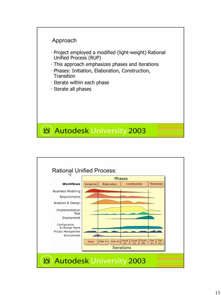
Project employed a modified (light-weight) Rational Unified Process (RUP)This approach emphasizes phases and iterationsPhases: Initiation, Elaboration, Construction, TransitionIterate within each phaseIterate all phases
Rational Unified Process:
14
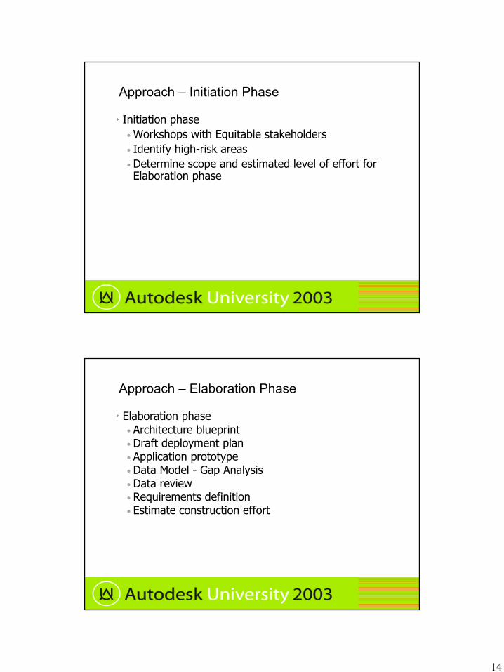
Approach – Initiation Phase
Initiation phase• Workshops with Equitable stakeholders• Identify high-risk areas• Determine scope and estimated level of effort for Elaboration phase
Approach – Elaboration Phase
Elaboration phase• Architecture blueprint• Draft deployment plan• Application prototype• Data Model - Gap Analysis• Data review• Requirements definition• Estimate construction effort

15
Approach – Construction PhaseConstruction phase• Data Migration
• DWG clean-up tools• Migration tools for DWG to new Oracle schema,
enforcing business rules• Migration pilot• Full migration
• Application development• Configuration• Development• Performance tuning• Three phase delivery
Approach – Transition Phase
Transition phase• Acceptance testing• User training• Production roll-out

16
Data Migration
Data problems in source DWG’s:• Inconsistent placement of features on layers• Inconsistent schema usage in object data tables• No attribute constraints – attribute values• Inconsistent drafting standards – between drafters, between divisions
• No connectivity (topology)• Labels are separate objects
Tiger for county polygons, municipality polygons and street names
Migration
DWG GINA
FME
Oracle
Gina_in
Old Schema
SQL
Data CleanupLabel PtsAssociationsConnections
New Schema
MAP 6
DRW Cleanup

17
Map tile cleanup
Manual clean-up:• Drafting group performed manual cleanup• E.g. Proper ODT structure (# of columns, column order)
• E.g. Features on proper layers
Map tile cleanup
Automated clean-up:• Audits run to ensure minimum manual clean-up has been done (e.g. all layers are valid; ODT structure correct)
• Automated cleanup is table driven for valid Block/Layer/ODT combinations
• Error Crawler – allows user to navigate to each error and correct within MAP
• Architecture - MAP based component, accessible via MAP command-line
18
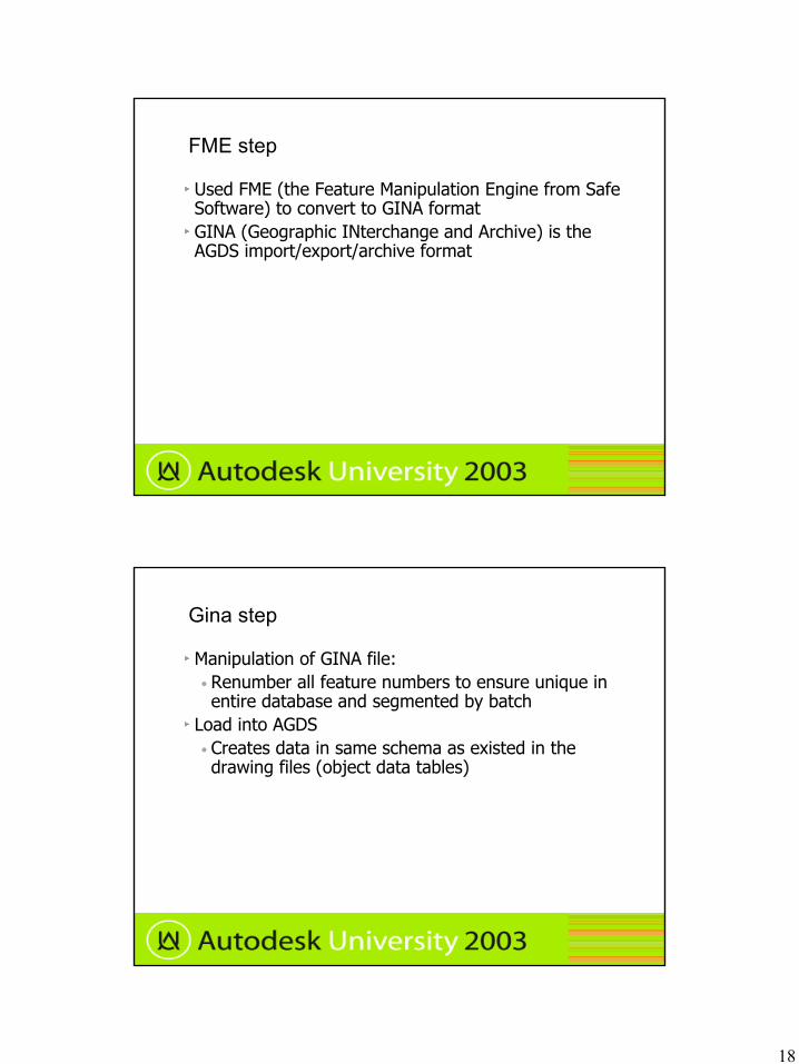
FME step
Used FME (the Feature Manipulation Engine from Safe Software) to convert to GINA formatGINA (Geographic INterchange and Archive) is the AGDS import/export/archive format
Gina step
Manipulation of GINA file:• Renumber all feature numbers to ensure unique in entire database and segmented by batch
Load into AGDS• Creates data in same schema as existed in the drawing files (object data tables)

19
Oracle clean-up
Move all data to new schemaMap attribute values to legal values• E.g. ‘2 ft’ is mapped to numeric value 2• Invalid values mapped to ‘$’ or ‘-9’ or 9/9/9999
Create labels• Match label objects based on GFIS ID
Connectivity – connect facilities if they are spatially coincidentService connectivity – based on spatial proximityAssociations – street centerlines to street names
Post Migration Clean-up
Review migration logsResolve unknown attribute valuesDefine pressure systems

20
AGDS Screen shot
Application Configuration and Enhancement
Application Configuration:• Object rules to match object model• Symbology• Traces and queries
Application Customization• autoconnect, • trace post-processing• Plot
21
MapGuide implementation
Much demand for data viewingInitially based off of drawing filesSoon to be based off of AGDS data
Results
Enterprise data and base applications are in placeStill using a MAP front end, so not much user training requiredHigher productivity in mapping department - Users are saving a lot of timeBacklog is reduced

22
Next phase
Goals:• 1) Integration with field design• 2) Integration with network analysis tool• 3) General productivity enhancements• 4) Platform upgrade
Next phase (Cont’d)
The following diagrams show the business process model of current state and desired future state for the Construction Work Order process

23
Field Office
M apping
Engineering
Capital Planning
Planning
Property Records
Field Office
M apping
Engineering
Capital Planning
Planning
Property Records
CompleteProject
Create CORequest Form andOptional Proposal
DWG
As-built toPropertyRecords
Request
As-builtto
Planning
Create/UpdateDWG to Reflect
As-builtConditions
UpdateDistribution
Maps
DistributePlots
Copy andDistribute
Analyze As-built
Update Maps
DistributionApproval
Create FieldNotes
Construct andTie- In
EngineeringApproval
CapitalPlanningApproval
CS_Construction Order (Process Chart)iAdvantage System Architect
Thu Sep 04, 2003 15:42Commen
.
Distric tManager /Superv isor
CapitalPlanning
Committee
ConstructionInspector
ConstructionOrder
DistributionMap
ConstructionInspector
ConstructionOrder
Engineer
TechnicalFieldman
TechnicalFieldman
EngineeringManager
TechnicalFieldman
AM/FMCoordinator
AM/FMCoordinator
As-builtDWG
OperationsAdministrator
AutoCADMap
AutoCADMap
DWG inAutoCAD
As-builtDWG
As-builtC.O.
As-builtDWG
As-builtDWG
DWG inAutoCAD
Field Notes
As-built to PlanningAs-built to Prop. Rec.
As-built to MappingAccept As-built
Not Approved
Approved
Eng Not OK
Cap Not OK
Reject As-built
Cap OK
Eng OK
<60 PSI
>60 PSI
Field Office
Mapping
Engineering
Capital Planning
Planning
Property Records
Field Office
Mapping
Engineering
Capital Planning
Planning
Property Records
Create/UpdateDWG to Reflect
As-built Conditions
QA Map andMake Minor
Edits in AGDS
EChangeto PropertyRecords
EChangeto FieldOffice
Create CORequest Formand Optional
Proposal DWG
EChangeto Planning
Post Job
RequestCreate Field
NotesDistribution
Approval
CapitalPlanningApproval
Eng ineeringApproval
Constructand Tie-In
FS_Construc tion Order (Process Chart)iAdvantage System Architect
Thu Sep 04, 2003 15:36Comm en
.
DistrictManager /Supervisor
CapitalPlanning
Committee
ConstructionOrder
ConstructionOrder
ConstructionInspector
Eng ineeringManager
ConstructionInspector
TechnicalFieldman
DWG inAutoCAD
DWG inAutoCAD
AM/FMCoordinator
FieldNotes
AGDSJob
TechnicalFieldman
As-builtDWG
As-builtDWG
AGDS Job
AGDS Job
EChange
EChange
EChange
EChange
EChangeEChange
>60 PSI<60 PSI
Eng OK
Cap OK
Reject Map
Accept MapEChg to Prop RecEChg to Planning
EChg to Field Off.
Cap Not OK
Eng Not OK
Approved
Not Approved

24
Next phase
How is this accomplished?• AGDS Long Transactions (a.k.a. Versions)• Integration with workflow• Symbology and View Modes
Versioned data
Can represent design data differently from in-ground facilities, using thickness, color, labels

25
Future
AutoDesk GIS Design Server
Oracle
Risk Assessment Optimain
Mobile Data MapGuide &
MDSI
System Planning AdvanticaStoner
Financial JD Edwards
CISReadi
ComplianceApplications
Questions

26
Summary
Data sharing between applications is the key to streamlined business processesProcess unificationNeed a foundation of enterprise GIS and communication architectureMigration from MAP tiles to AGDS
Thank You