gft ground fixed tilt installation guide -...
TRANSCRIPT

INSTALLATION GUIDE
PUB15JUN10
GFT GROUNDFIXEDTILT
NOTE: Refer to construction drawings
for project specific details. Construction drawings
have precedence over these installation guidelines.
NOTE: Refer to construction drawings
for project specific details. Construction drawings
have precedence over these installation guidelines.

TECHNICAL DATASHEETGFT GROUNDFIXEDTILT PAGE
PRIMARY COMPONENTS A
ITEM COMPONENT MATERIAL1 Roll- Formed Steel Pile 4" or 4.5 " x 6" C Shape (Length Varies by Project)2 Aluminum East-West Beam Aluminum Beam with Continuous Slots for Adjustability3 Roll-Formed Steel Top Chord C Shape with Custom Hole Pattern for Adjustability4 Roll-Formed Steel Diagonal Brace C Shape5 Steel Diagonal Brace Plate Steel Plate with Custom Hole Pattern for Adjustability6 End Clamp End Clamp Assembly with T-Bolt7 Mid Clamp Mid Clamp Assembly with T-Bolt8 Nested Splice Member Internal Aluminum Splice Retained with Self-Tapping Screws9 East-West Beam Clamp Aluminum Extruded Clamp with Stainless Steel Hardware
6
1
2
34
5
9
8
7

TECHNICAL DATASHEETGFT GROUNDFIXEDTILT PAGE
BOVERALL VIEW OF COMPONENTS
ITEM COMPONENT1 5" Top Chord Channel2 6" x 4" or 4.5" C-Shape Pile3 Diagonal Brace Assembly4 3.25" x 2" East-West Aluminum Beam5 (NOT USED)
6 Flat Washer 1/4"7 Hex Flange Nut 1/4-20 Serrated8 (NOT USED)
9 Flat Washer 5/8"10 Flat Washer 3/4"11 Hex Bolt 5/8-11" x 1-1/2"12 Hex Bolt 3/4-10" x 1-1/2"13 Hex Flange Nut 5/8-11 Serrated14 Hex Flange Nut 3/4-10 Serrated15 Hex Bolt 1/4-20 x 1"16 East-West Rail Clip17 End Clamp Assembly18 Mid Clamp Assembly19 PV Module (By Others)
1
2
3
4
6 7
9
9
10
11
11
12
13
13
14
15
16
17
19
18
TECHNICAL DATASHEETGFT GROUNDFIXEDTILT PAGE
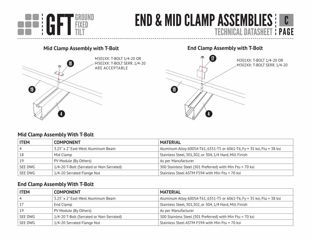
Mid Clamp Assembly with T-Bolt
C
End Clamp Assembly With T-Bolt
Mid Clamp Assembly With T-Bolt
END & MID CLAMP ASSEMBLIES
ITEM COMPONENT MATERIAL4 3.25" x 2" East-West Aluminum Beam Aluminum Alloy 6005A-T61, 6351-T5 or 6061-T6, Fy = 35 ksi, Ftu = 38 ksi
18 Mid Clamp Stainless Steel, 301,302, or 304, 1/4 Hard, Mill Finish
19 PV Module (By Others) As per Manufacturer
SEE DWG 1/4-20 T-Bolt (Serrated or Non-Serrated) 300 Stainless Steel (301 Preferred) with Min Ftu = 70 ksi
SEE DWG 1/4-20 Serrated Flange Nut Stainless Steel ASTM F594 with Min Ftu = 70 ksi
ITEM COMPONENT MATERIAL4 3.25" x 2" East-West Aluminum Beam Aluminum Alloy 6005A-T61, 6351-T5 or 6061-T6, Fy = 35 ksi, Ftu = 38 ksi
17 End Clamp Stainless Steel, 301,302, or 304, 1/4 Hard, Mill Finish
19 PV Module (By Others) As per Manufacturer
SEE DWG 1/4-20 T-Bolt (Serrated or Non-Serrated) 300 Stainless Steel (301 Preferred) with Min Ftu = 70 ksi
SEE DWG 1/4-20 Serrated Flange Nut Stainless Steel ASTM F594 with Min Ftu = 70 ksi
End Clamp Assembly with T-Bolt
M301XX: T-BOLT 1/4-20 ORM302XX: T-BOLT SERR. 1/4-20
4
17
19
M301XX: T-BOLT 1/4-20 ORM302XX: T-BOLT SERR. 1/4-20ARE ACCEPTABLE
4
19
18

TECHNICAL DATASHEETGFT GROUNDFIXEDTILT PAGE
ITEM COMPONENT MATERIAL4 3.25" x 2" East-West Aluminum Beam Aluminum Alloy 6005A-T61, 6351-T5 or 6061-T6, Fy = 35 ksi, Ftu = 38 ksi
5 East-West Beam Splice Insert Aluminum Alloy 6005A-T61, 6351-T5 or 6061-T6, Fy = 35 ksi, Ftu = 38 ksi
8 1/4" x 20 Self Drilling Screw (Buildex) Grade 5, ASTM A449/ SAE J429 (Similar Properties Confirmed by testing)
East-West Rail Clip
East-West Beam Splice
D
East-West Rail Clip
RAIL CLIP & BEAM SPLICE
ITEM COMPONENT MATERIAL4 3.25" x 2" East-West Aluminum Beam Aluminum Alloy 6005A-T61, 6351-T5 or 6061-T6, Fy = 35 ksi, Ftu = 38 ksi
6 Flat Washer 1/4" Stainless Steel ASTM F594 with Min Ftu = 70 ksi
7 Hex Flange Nut 1/4-20 Serrated 302HQ 18/8 Stainless Steel Austenitic 300 Series, Min Ftu = 85 ksi
15 Hex Bolt 1/4-20 x 1" 302HQ 18/8 Stainless Steel Austenitic 300 Series, Min Ftu = 85 ksi
16 East-West Rail Clip Aluminum Alloy 6005A-T61, 6351-T5 or 6061-T6, Fy = 35 ksi, Ftu = 38 ksi
East-West Beam Splice
4
4
8
5
6
4
7 15
16

TECHNICAL DATASHEETGFT GROUNDFIXEDTILT PAGE
Top Chord to Pile Connection
Top Chord to Pile Connection
Diagonal Brace Plate to Pile Connection
Diagonal Brace Plate to Pile Connection
EPILE CONNECTIONSTOP CHORD & DIAGONAL BRACE
ITEM COMPONENT MATERIAL1 5" Top Chord Channel Cold Rolled ASTM A653 HSLAS Grade 50 or 55
2 6" x 4 or 4.5" C-Shape Pile Cold Rolled ASTM A653 HSLAS Grade 50 or 55
10 Flat Washer 3/4" SAE Type A Narrow
12 Hex Bolt 3/4-10 x 1-1/2" SAE J429-Grade Varies per Project
14 Hex Flange Nut 3/4-10 Serrated SAE J429-Grade Varies per Project
ITEM COMPONENT MATERIAL2 6" x 4 or 4.5" C Shape Pile Cold Rolled ASTM A653 HSLAS Grade 50 or 55
3 Diagonal Brace Plate ASTM A36 or ASTM A653 GR 50 Steel
9 Flat Washer 5/8" SAE Type A Narrow
11 Hex Bolt 5/8-11 x1-1/2" SAE J429-Grade Varies per Project
13 Hex Flange Nut 5/8-11 Serrated SAE J429-Grade Varies per Project
20 Diagonal Brace Cold Rolled ASTM A653 HSLAS Grade 50 or 55
10 12 141
2
4X 9 11 13
2
2020
3

GFT GROUNDFIXEDTILT INSTALLATION GUIDE PAGE
INSTALL PILES
All piles within single table must be oriented to face
the same direction per the construction drawings.
Hole height above grade per construction drawings.
1
GFT GROUNDFIXEDTILT INSTALLATION GUIDE PAGE
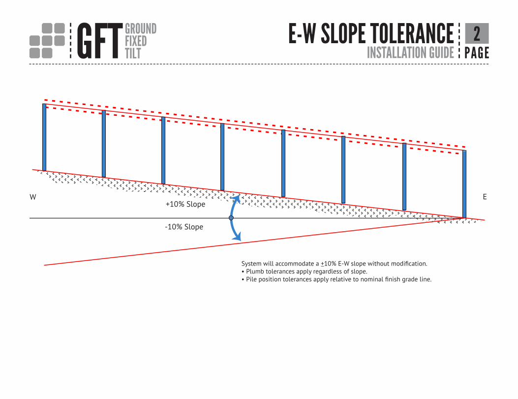
System will accommodate a +10% E-W slope without modification.• Plumb tolerances apply regardless of slope.• Pile position tolerances apply relative to nominal finish grade line.
E-W SLOPE TOLERANCE
W E+10% Slope
-10% Slope
2

GFT GROUNDFIXEDTILT INSTALLATION GUIDE PAGE
PILE POSITION & TOLERANCES
+1"
N-S+1°
Rotation +2°
E-W+1°
+ 1" E-W + 1" N-S
S
3
GFT GROUNDFIXEDTILT INSTALLATION GUIDE PAGE
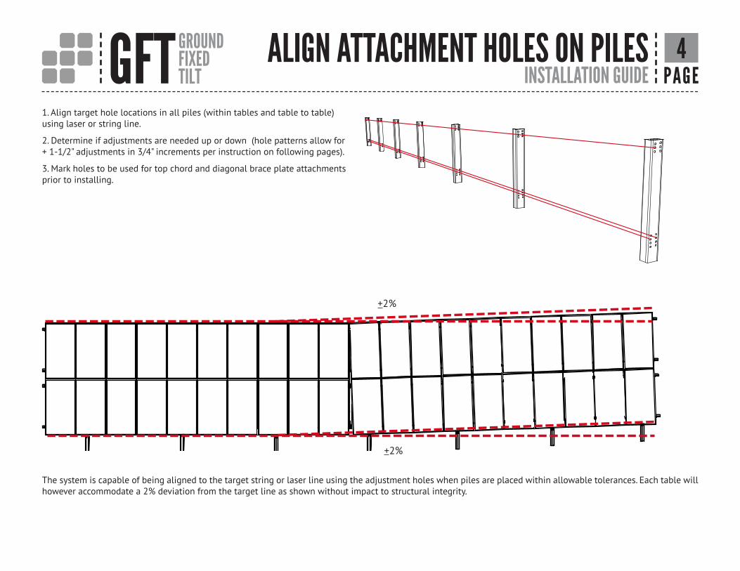
1. Align target hole locations in all piles (within tables and table to table) using laser or string line.
2. Determine if adjustments are needed up or down (hole patterns allow for + 1-1/2" adjustments in 3/4" increments per instruction on following pages).
3. Mark holes to be used for top chord and diagonal brace plate attachments prior to installing.
The system is capable of being aligned to the target string or laser line using the adjustment holes when piles are placed within allowable tolerances. Each table will however accommodate a 2% deviation from the target line as shown without impact to structural integrity.
ALIGN ATTACHMENT HOLES ON PILES
+2%_
4
+2%
GFT GROUNDFIXEDTILT INSTALLATION GUIDE PAGE
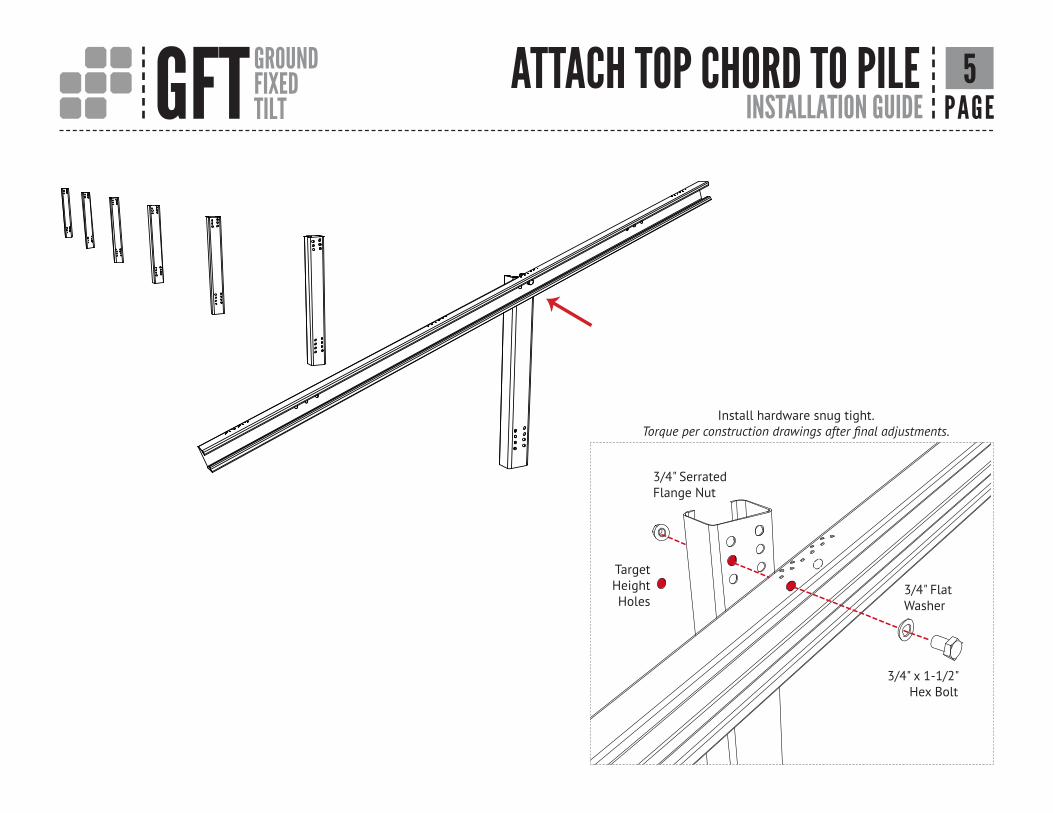
ATTACH TOP CHORD TO PILE
Install hardware snug tight. Torque per construction drawings after final adjustments.
3/4" Serrated Flange Nut
3/4" Flat Washer
3/4" x 1-1/2" Hex Bolt
Target HeightHoles
5

GFT GROUNDFIXEDTILT INSTALLATION GUIDE PAGE
TOP CHORD TO PILE ADJUSTMENT
Top Chord
Target Hole
Target Hole
Pile
Move top chord up or down (not horizontally) as needed to adjust
height in 3/4" increments.
Use single 3/4" bolt (nut and washer) at one of the locations
shown.
Target Height
Up 3/4"
Down 3/4"
Up 1-1/2"
Down 1-1/2"
Adjustment Locations (Single 3/4" Bolt)
Target Height
6

GFT GROUNDFIXEDTILT INSTALLATION GUIDE PAGE
DIAGONAL BRACE ASSEMBLY
Install hardware snug tight. Torque per construction drawings after final adjustments.
(2) 5/8" Serrated
Flange Nuts
Target Height Holes
(2) 5/8" x 1-1/2" Hex Bolts
(2) 5/8" Flat Washers
Diagonal Brace Assembly
7ATTACH PILE TO

GFT GROUNDFIXEDTILT INSTALLATION GUIDE PAGE
PILE ADJUSTMENT
Move diagonal brace plate up or down (not horizontally) as needed to
adjust height in 3/4" increments.
Use pair of 5/8" bolts (nuts and washers) atlocation shown.
Adjustment Locations (Pair of 5/8" Bolts)
Up 3/4"
Down 3/4"
Diagonal Brace Plate
Pile
Target Holes
Target Height
Target Height
Up 1-1/2"
Down 1-1/2"
8DIAGONAL BRACEASSEMBLY TO
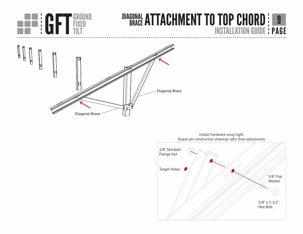
GFT GROUNDFIXEDTILT INSTALLATION GUIDE PAGE
ATTACHMENT TO TOP CHORD
Install hardware snug tight. Torque per construction drawings after final adjustments.
Diagonal Brace
Diagonal Brace
5/8" Serrated Flange Nut
Target Holes
5/8" Flat Washer
5/8" x 1-1/2" Hex Bolt
9DIAGONAL BRACE
GFT GROUNDFIXEDTILT INSTALLATION GUIDE PAGE
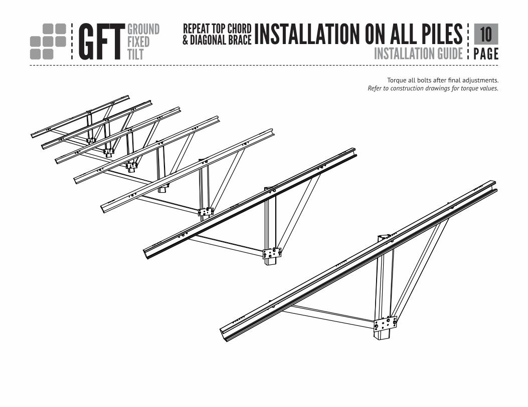
INSTALLATION ON ALL PILESTorque all bolts after final adjustments.
Refer to construction drawings for torque values.
10REPEAT TOP CHORD & DIAGONAL BRACE

GFT GROUNDFIXEDTILT INSTALLATION GUIDE PAGE
TOP CHORD TILT ADJUSTMENT
If required, additional minor adjustment of top chord angle may be achieved by a combined repositioning of diagonal braces to adjacent holes in top chord
and diagonal brace plate.
11

GFT GROUNDFIXEDTILT INSTALLATION GUIDE PAGE
1. Align target hole locations using laser or string line.
2. Determine if adjustments are needed up or down. (hole patterns allow for +1" adjustment in 1/2" increments per instruction on following pages).
3. Mark holes to be used for attaching E-W beams prior to installing.
Target beam clamp holes
12HOLELOCATIONS E-W BEAM TO TOP CHORD
GFT GROUNDFIXEDTILT INSTALLATION GUIDE PAGE
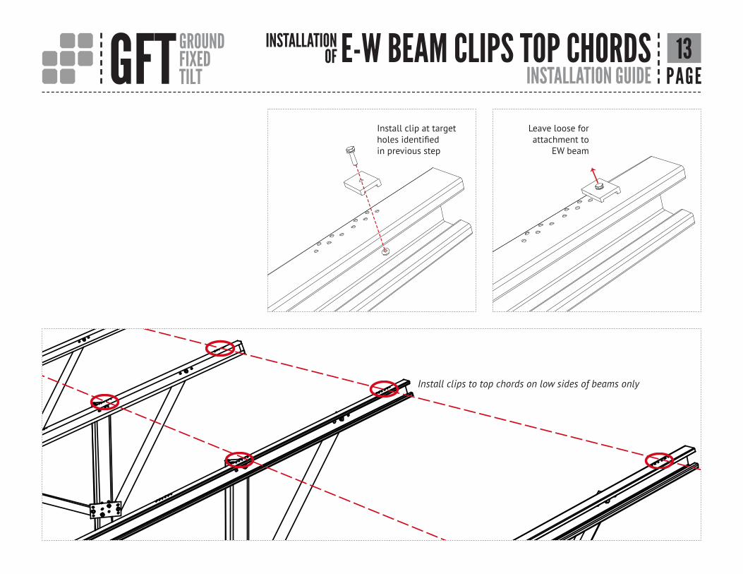
E-W BEAM CLIPS TOP CHORDS
Install clip at target holes identified in previous step
Leave loose for attachment to
EW beam
Install clips to top chords on low sides of beams only
13INSTALLATIONOF

GFT GROUNDFIXEDTILT INSTALLATION GUIDE PAGE
INSTALL E-W BEAMS
Install first set of top row E-W beams starting at either end of table
14

GFT GROUNDFIXEDTILT INSTALLATION GUIDE PAGE
ATTACH E-W BEAMS TO TOP CHORDS1. Position E-W Beam
2. Insert lower clip into
beam slot
3. Install upper clips and hardware
4. Torque bolts per construction drawings
Rotational adjustment to align top chords may be made prior to tightening beam clamps
Set beam E-W position per construction drawings
15

GFT GROUNDFIXEDTILT INSTALLATION GUIDE PAGE
INSTALL E-W BEAM SPLICES
Insert splices into ends of installed E-W beams.
Insert splice to 1/2" splice length (12")
* Install self-tapping screw through one wall of beam and splice
Slide next E-W beam on to splice
No Gap
5" to 7"
5" to 7"
Centerline +1/8" *Install self-tapping screw
* Self-tapping screws may be installed on either side (N or S) of the E-W beam
16
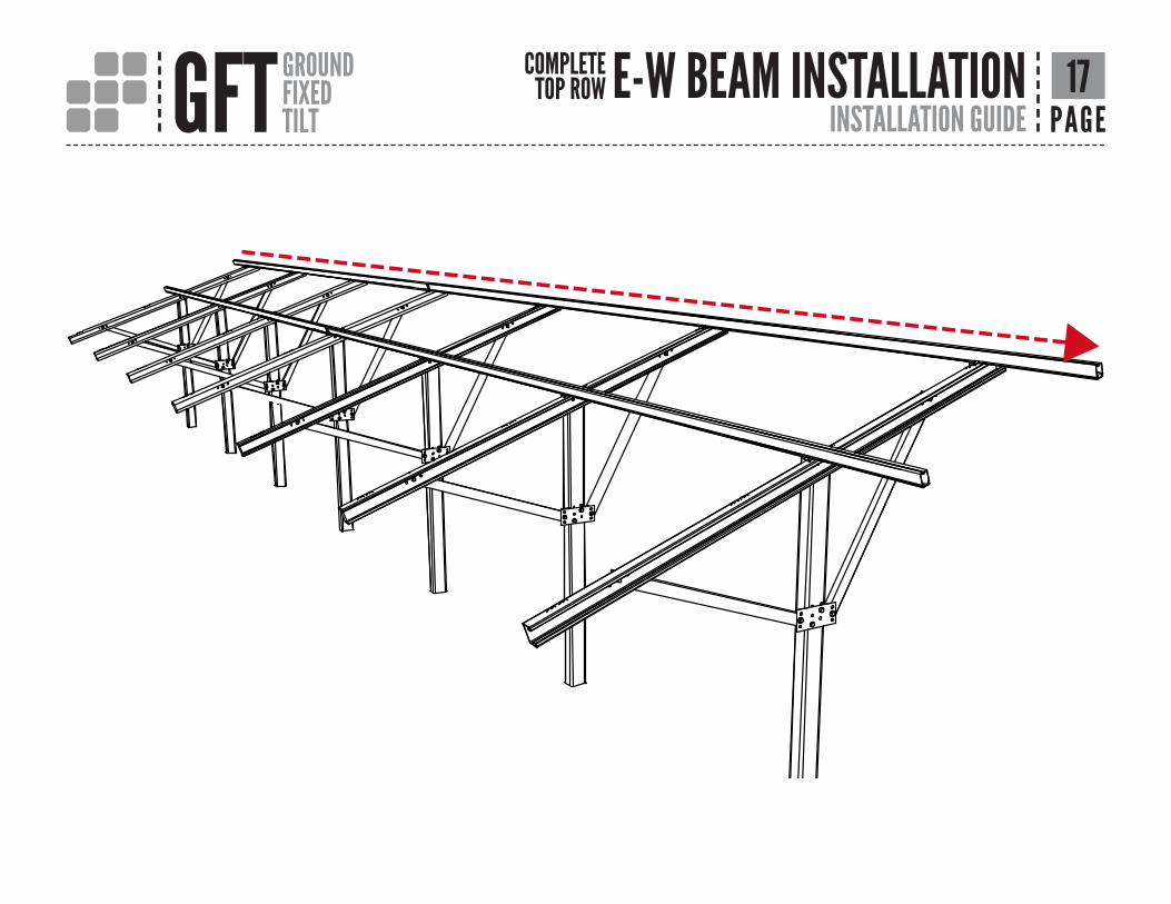
GFT GROUNDFIXEDTILT INSTALLATION GUIDE PAGE
E-W BEAM INSTALLATION 17COMPLETE TOP ROW

GFT GROUNDFIXEDTILT INSTALLATION GUIDE PAGE
INSTALL MODULE W/END CLAMPS
Rotate bolt into position
Insert T-bolt into rail
Install End Clamps* Refer to construction drawings or module installation guidelines for module mounting locations and limits.
Install End Module• Place module on rails• Engage module with end clamps• Align and square module• Torque nuts to 10ft-lbs
Serrated T- Bolts Non-Serrated T- Bolts
Verify that bolt position indicator
is perpendicular to E-W beam
Verify that bolt position indicator
is as shown
DETAIL CSCALE 1 : 1
DETAIL DSCALE 1 : 1
C
D
1/2" min
*
*
18

GFT GROUNDFIXEDTILT INSTALLATION GUIDE PAGE
DETAIL DSCALE 1 : 1
INSTALL MID CLAMPS ON 1ST MODULE
Insert T-bolt into
rail Rotate bolt into position
Position clamp on module. Do not tighten nut until next module is in place.
19
Verify that bolt position indicator
is perpendicular to E-W beam
Verify that bolt position indicator
is as shown
Serrated T- Bolts Non-Serrated T- Bolts
Install Mid Clamps(Position upright against module but do not torque)
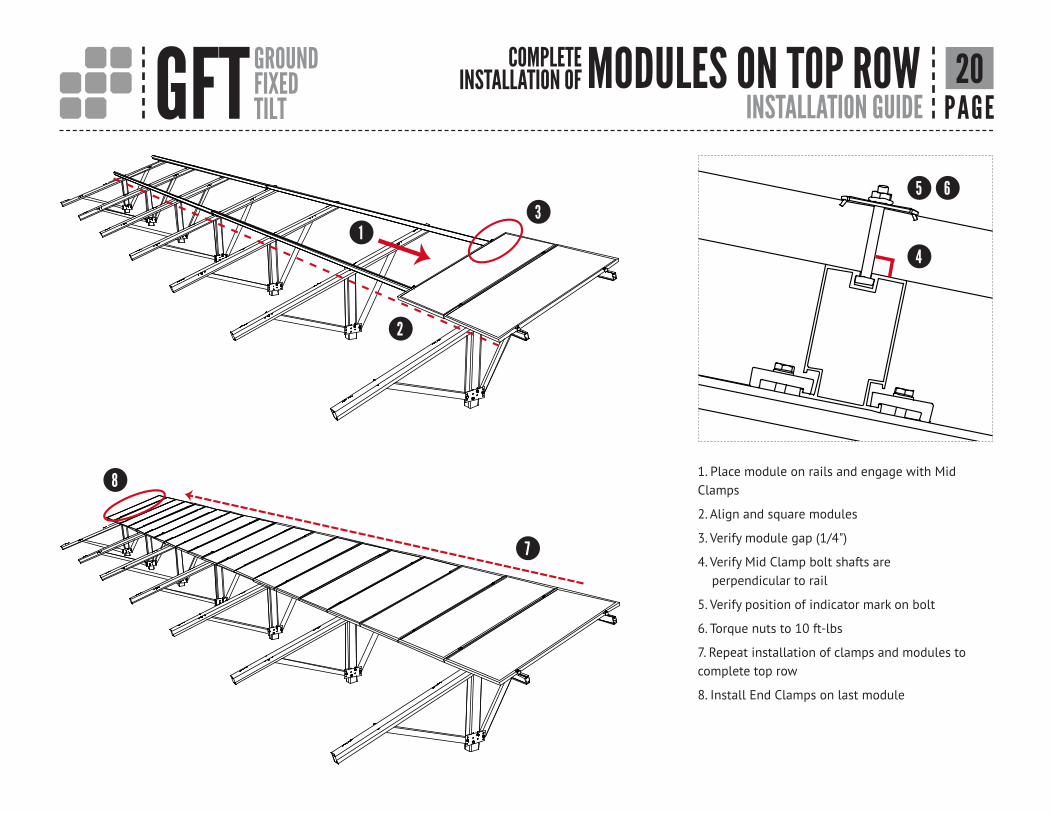
GFT GROUNDFIXEDTILT INSTALLATION GUIDE PAGE
MODULES ON TOP ROW
1. Place module on rails and engage with Mid Clamps
2. Align and square modules
3. Verify module gap (1/4")
4. Verify Mid Clamp bolt shafts are perpendicular to rail
5. Verify position of indicator mark on bolt
6. Torque nuts to 10 ft-lbs
7. Repeat installation of clamps and modules to complete top row
8. Install End Clamps on last module
20COMPLETE INSTALLATION OF
6
1
2
3
4
5
8
7

GFT GROUNDFIXEDTILT INSTALLATION GUIDE PAGE
E-W BEAM ON BOTTOM ROW 21REPEAT INSTALLATION OF

GFT GROUNDFIXEDTILT INSTALLATION GUIDE PAGE
MODULES ON BOTTOM ROW 22REPEAT INSTALLATION OF

GFT GROUNDFIXEDTILT INSTALLATION GUIDE PAGE
ELECTRICAL CONSIDERATIONS
The entire Unirac GFT table has been classified for grounding & bonding to UL2703. The bonding path has been evaluated from the PV module frame all the way through
to the pile. The following are suggestions to aid in grounding of the table for the project electrical engineer of record, and by the local authority having jurisdiction.
GROUND LUG MOUNTING DETAILSDetails are provided for both the WEEB and Ilsco products. The WEEBLug has a grounding symbol located on the lug assembly. The Ilsco lug has a green colored set screw for grounding indication purposes. One lug is recommended per GFT table. Installation must be in accordance with NFPA NEC70, however the electrical designer of record should refer to the latest revision of National Electrical Code (NEC) for actual grounding conductor cable size. Unirac GFT is intended to be used with PV modules that have a system voltage less than or equal to 1,000VDC. A minimum 10AWG, 105°C copper grounding conductor should be used to ground the system according to the (NEC) and the authority having jurisdiction. It is the installers responsibility to check local codes, which may vary.
TEMPORARY BONDING CONNECTION DURING ARRAY MAINTENANCEWhen removing modules for replacement or system maintenance, any module left in place that is secured with a bonding mid-clamp will be properly grounded. If a module adjacent to the end of a row is removed, or if any other maintenance condition leaves a module without a bonding mid clamp, a temporary bonding connection must be installed as follows:• Attach Ilsco GBL-4DBT or WeebLug 6.7 to both modules on either side of the module that has been removed. Note: The lug should be attached to the manufacturers designated grounding point on the frame.• Install a solid #6 Awg copper wire to both grounding lugs.
The following grounding & bonding components have been certified to be compatible with Unirac GFT:• Wiley WEEBLug (P/N 0080025) Torque 1/4"
mounting hardware to 10ft-lbs. See product data sheet for conductor size and conductor fastener torque.
• Ilsco Lay-in Lug (P/N GBL-4DBT) Torque 10-32 mounting hardware to 5ft-lbs. See product data sheet for conductor size and conductor fastener torque.
Ground LugWEEBLugIlsco
Bolt size1/4"-20#10-32
Drill size17/64"7/31"
23
Steel C-Shape Pile
NOTE: Details are provided for both the WEEB and Ilsco products
WEEBLug 6.7 Ground LugUNIRAC P/N:0080025
Ilsco GBL-4DBT Ground LugNOTE: Is for single use only

GFT GROUNDFIXEDTILT INSTALLATION GUIDE PAGE
MODULE COMPATIBILITYMANUFACTURER MODEL
Canadian Solar...... . . . . . . . . . . . . . . .CS6X-PCanadian Solar...... . . . . . . . . . . . . . . .CS6P-MCanadian Solar...... . . . . . . . . . . . . . . .CS6P-PCanadian Solar...... . . . . . . . . . . . . . . .ELPS CS6P-MMCanadian Solar...... . . . . . . . . . . . . . . .ELPS CS6A-MM Jinko Solar...... . . . . . . . . . . . . . . . . . . . . . Standard-60Jinko Solar...... . . . . . . . . . . . . . . . . . . . . . Standard-72Jinko Solar...... . . . . . . . . . . . . . . . . . . . . . Standard-96LG Solar...... . . . . . . . . . . . . . . . . . . . . . . . . .Mono X NeonLG Solar...... . . . . . . . . . . . . . . . . . . . . . . . . . Mono XREC....... . . . . . . . . . . . . . . . . . . . . . . . . . . . . . . PE72SolarWorld...... . . . . . . . . . . . . . . . . . . . . .Sunmodule PlusSolarWorld...... . . . . . . . . . . . . . . . . . . . .Sunmodule Pro XLSolarWorld...... . . . . . . . . . . . . . . . . . . . . .Sunmodule ProtectSunPower...... . . . . . . . . . . . . . . . . . . . . . . X21 SeriesSunPower...... . . . . . . . . . . . . . . . . . . . . . . E20/200 Series-72 CellSunPower...... . . . . . . . . . . . . . . . . . . . . . . E20 Series-96 CellTrina...... . . . . . . . . . . . . . . . . . . . . . . . . . . . . . .PA05 60-cell Universal ModuleYingli..... . . . . . . . . . . . . . . . . . . . . . . . . . . . . . .YGE 60 Cell SeriesYingli..... . . . . . . . . . . . . . . . . . . . . . . . . . . . . . .YGE-U 72 Cell SeriesYingli..... . . . . . . . . . . . . . . . . . . . . . . . . . . . . . .Panda 60 Cell Series
24BONDING & GROUNDING APPROVED