getting to know your klee sequencer - modular.fonik.de · 1 getting to know your klee sequencer...
TRANSCRIPT

1
Getting to Know Your Klee Sequencer
Quite possibly, the first question you may have is: What is a Klee Sequencer?
We’re glad you asked. It’s a fairly short answer that is best understood through a fairly lengthy explanation. We’ll try not to make it too lengthy.
A Klee sequencer is merely a variant of the standard step sequencer. It differs in one more-or-less minor detail: where a standard step sequencer sequentially addresses a row of controls, one control at a time to produce a stepped voltage pattern the Klee sequencer will address a row of controls any number of controls at a time to produce a stepped voltage pattern.
After that explanation, you may be thinking “Whoa….wait a minute. Say what? What do you mean “any number of controls” – you lost me.” If that’s the case, you certainly are not alone. Perhaps a more direct and simplistic answer may go along the lines of “You know how on your step sequencer, you have one light that runs across the display? Well, the Klee can have more than one light that runs across its display”.
To operate a Klee sequencer, it’s not necessary to know all of the information contained in this section. In a way, studying this almost runs counter to the philosophy of the Klee Sequencer. At the same time, for most people, it can be frustrating experience to have a new instrument, but no clue as to what it actually does. And, truthfully, gleaning any amount of information here may well lead you to getting the most out of your Klee Sequencer.
So, if you want to know what makes a Klee Sequencer tick, read on. Be sure to pause here and there, flip some switches and turn some knobs and enjoy yourself with the Klee Sequencer.
The Klee Pattern ExposedA Klee Sequencer is a step sequencer at heart, but with that all important twist of being able to select more than one step (or “stage” in Klee parlance) at a time. To wrap your head and around why this makes such a difference, a brief review of how a standard step sequencer works is in order. Even if you are already familiar with the function of the step sequencer, it is recommended that you follow the review – certain points are made concerning what differentiates the Klee Sequencer from a standard step sequencer.
A step sequencer is a device that produces a number of voltage steps by programming a row of potentiometers with the desired step intervals, and then selecting each step sequentially, one by one, to produce a voltage output. Usually, a step sequencer may have a row of eight potentiometers or a row of sixteen potentiometers or even more, depending on the model of step sequencer you have. Usually, above each potentiometer in this row is an LED. So, we have a row of LEDs above our row of potentiometers, one LED per potentiometer. Only one of these LEDs can be illuminated at any given time, and there will always be one of them illuminated.

2
Figure 1: A simple step sequencer
Figure 1 depicts a simple step sequencer. Note that the LED over Step 1 is illuminated in red. When the step sequencer is clocked, the position of the illuminated LED will shift sequentially with each clock pulse, usually moving from left to right across the row of LEDs, as illustrated in Figure 2.
Figure 2: Clock pulse shifting active step from Step 1 to Step 2.
As each LED lights up, the sequencer will send the voltage programmed by the pot directly below the illuminated LED out of the voltage output connector of the sequencer. Of course, this voltage can be used to control any parameter in a voltage controlled synthesizer – it can control filter cutoff or VCO frequency or any number of other parameters. Let’s, for the sake of example, say our sequencer is controlling a VCO. And, for brevity, let’s say our sequencer is an eight step sequencer – in other words, it has a row of eight potentiometers with a row of eight LEDs above it, as in Figures 1 and 2. And, finally, let’s say we want to tune our VCO to play an eight note ditty with our sequencer. How about the note sequence “ABACABAC”?
To program your eight step sequencer, you would first plug the voltage output of the sequencer into the V/Oct input of the VCO. Then you would illuminate the first LED

3
above the first pot and tune the VCO to “A” using the first pot. Which “A” you may ask slyly, “high A”, “low A”? – that’s up to you – it’s your tune!
Once the VCO is producing our “A” pitch, we move the illuminated LED one step to the right, so now it is above the second pot in the row. Because the illuminated LED is above our second pot, the step sequencer is now putting out the voltage set by adjusting the second pot in the row, so we tune that second pot for our second note, which is “B”. And so forth and so on until all eight of the pots are tuned from left to right “ABACABAC”.
Figure 3: Sequencer tuned to play “ABACABAC”
Now, we start clocking the step sequencer by feeding it a clock signal. Each time the clock signal goes from low to high, our illuminated LED shifts right. When it reaches the end, at step eight, the LED will jump back to the first step and repeat the “ABACABAC” sequence again – repeatedly - for as long as you can stand to listen to it.
Figure 4: Snapshot of running sequence – Step 4 is selected, which tunes VCO to C

4
You have now created a rhythmic backdrop of notes upon which you can build your next great composition. “ABACABACABACABACABACABACABACABAC…” The pitch of each step is tuned with the pots, and the tempo is determined by how fast your clock signal is running. The row of LEDs indicates which pot or ‘note’ is active at any given time.
Now, before moving on to the Klee, let’s just analyze exactly what is happening with our step sequencer – how it is really performing its task.
First of all, let’s look at what happens when we tune a pot for a certain pitch. In a one volt per octave system, it takes only one twelfth of one volt to move the pitch of an oscillator one half step. Let’s just say that our resting pitch of the VCO is already at the note “A”. That means we don’t have to apply any additional voltage to get the VCO to A, so our first pot is set for 0V.
Our second note is B. B is one full step, or two half steps, above A. So the second pot now must be tuned two half steps above the first pot – two half steps is two twelfths of a volt or one sixth of a volt, so pot number 2 is tuned to one sixth of a volt ( 0.167 Volts, rounded off).
The third pot tunes the VCO to A again, so it’s set for 0V. The fourth pot is tuned for C, which is three half steps above A, which is three twelfths of a volt or one fourth of a volt (0.25 Volts), so the fourth pot is adjusted to send out 0.25V. The same voltage rules apply for the rest of our pots. So, when our happy little LED steps from left to right, the voltage on the output of the sequencer is thus:
0V 0.167V 0V 0.25V 0V 0.167V 0V 0.25V
..over and over again.
Figure 5: Programmed voltages corresponding to ABACABAC
Don’t worry, you really don’t have to know what each voltage is when operating a Klee sequencer no more than you need to know it when operating a standard step sequencer. We’re just going through this exercise in order to understand what it is the Klee does.

5
Now, let’s set our voltages aside a second and look at our illuminated LED. As our illuminated LED glides from left to right, it’s obvious that, at any given time, only one LED is lit. So, our LED can only select one pot at any time. Thus, our output voltage will always be one of the voltages selected on one of our programming pots.
We’re getting very close to exactly what it is makes a Klee sequencer a Klee sequencer, but first, we’re going to introduce a term with which you most likely are already familiar with – that term is “Shift Register”.
Picture a row of eight binary digits – this is our register. Being binary numbers, each digit can only be a “1” (meaning “on”) or “0” (meaning “off”). Our example register represents our eight LEDs in our example step sequencer. The left-most digit is step one, and the right-most digit is step eight:
10000000
Notice that our left-most digit, representing step one, is a “1” and the rest of the digits are “0”. This means that step one is on, and our sequencer is putting out our first note, which is “A”.
A shift register is a special type of register that can shift its contents either left or right. In our case, we always shift our contents right (some step sequencers can shift left or “reverse”, but that’s beside the point here). When a clock pulse causes our illuminated LED to move from step one to step two, it’s doing exactly what a shift register would do. In this case, our shift register now looks like this:
01000000
You see our “1” shifted one step right. Now step 2 is on, and all of the other steps are off. The next clock pulse again causes our illuminated LED to move another step towards the right, selecting step three on our sequencer. Now our shift register can be represented as follows:
00100000
Figure 6: “00100000” represented on Sequencer LEDs
This continues until our illuminated LED is lighting up step 8:
00000001

6
After step 8, instead of our LED just dropping off into the void, it merely wraps around to the beginning, and we are back to:
10000000
So, it can be said that our standard sequencer operates using a shift register containing a one active bit pattern to select which of the eight steps is active. In fact, any standard step sequencer works off of a shift register with one active bit.
So finally, here it is: The Klee sequencer operates off of a shift register that can have more than one active bit in the register.
So what, that’s it? That’s the difference?
Yes, in a nutshell, that’s it. Your Klee Sequencer is capable of having in its shift register this pattern:
10001000
Or this:
10100010
Or even this:
10110010
Figure 7: Klee Pattern“10110010” represented on Klee Sequencer LEDs
In this manual, we call these patterns “Klee patterns”. In fact, the Klee pattern can be as long as 16 bits, such as this:
1010001010001000
Because a Klee pattern can be as many as 16 bits long, there are 65,536 different combinations of bits that can be programmed into the Klee.

7
So, exactly what does this mean, being able to program more than one bit into a sequencer shift register?
For one thing, it means that the standard method of programming a sequencer, in essence, flies out the window.
And why is that? Because now instead of selecting the voltage programmed by only one pot with a single illuminated LED, the Klee sequencer selects the summed voltages of more than one pot with more than one simultaneously illuminated LED.
Let’s go back to our eight step sequencer example, using our little tune ABACABAC. Only now, our eight step sequencer is a Klee sequencer. Because we can, instead of starting with the standard sequencer shift register pattern of:
1000000
We’ll instead begin with the Klee pattern of:
10100000
Notice in this example, we’ve added only one bit to our standard shift register pattern. Refer to figure 8. This pattern shows us that on our first stage, pot one and pot three are both selected to output their voltages to the Klee voltage output. Because there are two voltages selected by the LEDs, the sum of the two voltages will be generated. The first note of our tune is A and our third note is also A. In this case, if you recall, we have our VCO sitting at A, so we programmed both of these pots for 0V. 0 + 0 = 0, so we will still put out 0V for this first step. So, our first note will still be A.
Figure 8: First step in sequence using 01010000 as the Klee Pattern

8
Now a rising clock pulse shifts our shift register right one step. We have now shifted from Step 1 to Step 2, and we now have the pattern:
01010000
Refer to figure 9. The LED over pot two is illuminated so its programmed voltage for note B is generated (0.167V rounded off). And our LED over pot four is illuminated, so its programmed voltage for note C is generated (0.25V). Our two voltages are summed together at the Klee voltage output. 0.167 + 0.25 = 0.417, so now the Klee is generating 0.417V. That 0.417 is an interval of 5 half steps, or two and a half whole steps, above our resting frequency of A. So, instead of the note B being our second note in the ditty, it is now the note D, which is five half steps above A.
Figure 9: Second step in sequence has shifted to 01010000, producing the note ‘D’
Now another rising clock pulse shifts our shift register to the right one step again, and we are presented with this pattern:
00101000
In figure 10, we see the LED over pot three is illuminated. In our example, pot three is programmed for 0V, so it contributes 0V to the Klee voltage output. The LED over pot five is illuminated, and pot five is programmed for 0V as well, so our summed output is 0V – the third note is again A, as in the original ABACABAC.

9
Figure 10: Third step in sequence has shifted to 00101000, producing the note ‘A’
Yet again, we shift to the right:
00010100
In Figure 11, we see pot four, which is set for 0.25V, is selected, and pot six, which is set for 0.167V, is selected, and again we are presented with the summed voltage of 0.417V, which puts us back at note D again.
Figure 11: Fourth step in sequence has shifted to 00010100, producing the note ‘D’
To make a long story short, this pattern with this combination of pot settings will produce, instead of the sequence ABACABAC, the sequence ADADADAD.
If we change our Klee pattern to 11010000 , our ditty changes to DBDCDBDC!

10
And, if we get really crazy and enter a Klee pattern like 00010001, we get FAC#AFAC#A.
So, we have, without adjusting a single pot from its original settings, obtained fourunique note sequences from the same settings (there are of course, more patterns that could be applied, but, hey, we said this explanation would be as brief as possible).
This example is actually a quite simple example of Klee sequencing – if you notice, our original sequence of ABACABAC contained only three different notes, and those notes are symmetrically spaced. If you had a sequence that contained four different notes not so symmetrically spaced, the variation would increase.
Take for example, for whatever reason, our original sequence contained these notes: ABDCACDB. Using the same example patterns, we wind up with:
10100000 = DDDFDDDC#11010000 = DEG#FDFF#E00010001 = DADGDADGD
Notice that pattern 11010000 turned our sequence ABDCACDB, which contains four different pitches, into a pattern that contains five different pitches! The first and third patterns reduced the number of different pitches contained in the sequence from four to three.
So, manipulation of the pattern switches can render wildly varying results from the same set of programmed pots. What effect does changing the pot values have with a given pattern? Plenty, as it turns out. Take again our ABDCACDB sequence. Let’s just change it ever so slightly by raising one note a half step. Say the first note, A. So now our original one active bit shift register sequence is A#BDCACDB. Let’s apply the 11010000 pattern to that.
Raising the first note one half step and using 11010000 as our Klee pattern converts DEG#FDFF#E to D#EG#FDF#F#F. Though we only changed one of the notes in the original sequence, three notes actually changed in the Klee sequence: The first note changed from D to D#, the sixth note changed from F to F#, and the eighth note changed from E to F. Each of those notes was raised one half step, the same increment by which we changed the first note in the original one bit sequence. The reason for that is, because there are three bits in the Klee pattern, the altered note is going to be selected and combined with some other note or notes three times through one repetition of the sequence. Which notes it’s combined with is determined by the Klee pattern itself.
In other words, changing one pot’s programming is interactive with the entire sequence –unlike a standard sequencer that alters only one note in a sequence when one programming pot is adjusted, the Klee pattern will cause other notes in the pattern to change when only one pot is adjusted, and the affected notes will change by the same increment that the one pot has been adjusted for.

11
Ok, we’ll pause for a breather here and get caught up with some questions that may have formed in your mind.
Questions such as: “Can the Klee Sequencer produce note sequences not possible on a standard sequencer?”
The answer to that question is both “no” and “sort of”.
The “no” portion of the answer is, no, the Klee sequencer is still a step sequencer at heart – you could emulate any of its voltage sequences with a standard sequencer, but through a different method of programming.
The “sort of” portion of the answer is that, while a step sequencer could emulate a Klee sequence if it was programmed to do so, it would require three sixteen stage sections to do it fully, depending on what was to be “copied” from a massive Klee sequence. It hasn’t been discussed yet, but the Klee sequencer can actually produce three unique sixteen step voltage sequences from its one set of sixteen programming pots, or even patterns as long as thirty two steps. The first eight programming pots can process the Klee pattern and produce stepped voltage sequence programmed by those pots, the second row of eight pots produce a differently programmed stepped voltage sequence from the same pattern, and the third output is the stepped voltage sequence derived from the sum of the first two. All of these sequences are unique, but interrelated as well.
The Klee is capable of manipulating the pattern on the fly, so dynamic sequences in which some control is altered while the sequence is running would be difficult to reproduce with a standard step sequencer. One as-yet-un-discussed function actually manipulates the the number of bits in a Klee sequence – in that case, it would require three thirty two step standard sequencer rows to emulate some of those sequences.
“So”, you may ask “other step sequencers provide additional rows of pots to provide individual outputs, so why bother with a Klee sequencer – what is the purpose of using one, over a “normal” step sequencer which seems to be more predictable in terms of programming a sequence.”
There are a number of answers to that question. The first answer would be, of course, the Klee can be used as a standard step sequencer by programming only one active bit in a Klee pattern. But, in that instance there is very little reason to justify all of the circuitry inside the Klee and some of the control structure on the front panel of the Klee. Instead, one of the main intents of the Klee sequencer is indeed the unpredictability of what a single change in programming controls will do.
In fact, programming a Klee sequence is an exercise in the unpredictable. The programming pots interact with each other according to the Klee pattern driving them, and the Klee pattern itself is as instantly changeable as programming a pot. Some changes will shift your Klee sequence in a slightly different direction, while some

12
changes may shift the flow of things one hundred eighty degrees. In fact, the Klee gets its name from this concept. When the first model was designed, programming it was compared to molding a sculpture out of very loose clay. Some time after that statement, Romeo Fahl built a version of the first Klee model, and named it the Klee (which is pronounced ‘clay’) both in recognition of the “loose clay” description and in honor of the artist Paul Klee, whose work often, somehow, reflects the abstract nature of programming a Klee sequencer and many of the sequences it’s been known to produce.
As such, the Klee sequencer was designed to be used as a creative tool in composing and performing music. The Klee presents its user with a myriad of patterns, possibilities and choices. The act of programming a Klee sequence and experimenting with different patterns and program settings is intended to be an act of exploration into new branches of rhythm and music. In fact, this section of the operations manual is only intended to allow the user to know what the controls do – it’s not intended to suggest to the Klee operator that he should resort to pen and paper to try to construct a Klee sequence ‘logically’.
The concept is much the same thing as looking at the sky, and instead of seeing a cloud, suddenly seeing a winged horse or perhaps the Statue of Liberty. Within the practically limitless possibility of note sequences, tempo, and timing, a pattern may be recognized and formed into a musical image in your brain. Something will inevitably reach out and inspire you and lead you in a direction you perhaps had never considered before. From that point, the Klee sequence you’ve created may very well become the basis of a new composition that perhaps otherwise would never have occurred to you.
There’s all that, and there’s also the fact that so far we have only discussed the Klee in terms of the voltage patterns it produces. There is another aspect to the Klee that is as integral as to a Klee sequence as fingers are integral to a hand – the timing signals produced by the Klee Gate Bus.
The Klee Gate BusJust as the Klee sequencer applies a pattern programmed into the sequencer’s shift register to produce wildly varying voltage patterns, it derives a number of gate and trigger signals from this same pattern. Because the same shift register pattern that is used to produce the voltage pattern is also used to produce these timing signals, the timing signals and voltage pattern are interlocked in a very special way – a change in the Klee pattern will produce not only a change in the voltage pattern, it will also produce a change in the timing and number of the gates and triggers produced in each repetition of the pattern.
To explain the Klee Gate Bus adequately, we probably should first go back to our point of reference – the standard step sequencer.
Normally a step sequencer will produce a series of gate signals so that external devices can be synchronized to the step sequencer. The most basic control signal produced by thestep sequencer is an output connector that produces one gate per clock cycle.

13
Figure 12: Sequencer with basic gate output
If you plug this gate signal into an envelope generator that is controlling a VCA, or even gate the VCA with the gate signal, you get one note per step in the sequencer. If you pass the signal produced by a VCO that is controlled by the voltage output of the step sequencer through this VCA, a series of discrete notes is produced by the step sequencer, the VCO, and VCA. Of course, a filter is usually in there between the VCO and VCA, but this is one of the most basic and general applications of a step sequencer. If there is an eight step sequence, then eight notes are produced each time the sequence repeats.
Figure 13: Basic VCO/VCA Patch using sequencer gate signal
With this basic patch, the note length of each note does not vary, nor are there any ‘rests’ between notes – it is a constant cycle of the notes over and over. This, of course, can be very useful and has indeed been very useful in setting up rhythmic foundations in various musical pieces over the years.

14
Often, however, one may want to generate a sequence that provides variation either in note duration, or in timing (for example, one may want to have a series of notes, but alsoa rest or silence for a step or quarter step in there somewhere).
Various models of step sequencers provide a means to vary the note length. For example, some step sequencers offer a way to vary the on-time of the gates the sequencer produces – this allows some notes to last longer than others.
Figure 14: Varying the duty cycle of the gate to control note/rest length
Many step sequencers also allow a method to send only certain gate signals on certain steps. By doing this, one could, say, have the first, second and third steps produce a gate signal to generate three notes in succession, then perhaps have the sixth and seventh steps produce a couple of more gates, so that the first, second, third, sixth and seventh notes “sound”, while the fourth, fifth, and eighth steps produce no note at all, and are ‘rests’ in the sequence.
There are a few different methods step sequencers employ to generate gate signals only on certain steps in the sequence. One method is to provide one gate output per step. Often, a gate output jack will be placed right beneath every step programming pot. Whena particular step is accessed by the illuminated LED, a gate signal is produced on the output associated with that step. Then, the user is free to patch these different gate signals where he pleases.

15
Figure 15: Step sequencer with individual gate outputs
This is a very useful application – for example, half the gates can be used to control one device while the other half controls another device. This is great for stereo ping-pong type effects, for example. Of course, with this configuration, you are not limited to gating two devices – you can gate as many devices as you have steps. For example, for the simple sequencer pictured in Figure 15, one could gate as many as eight voices – in this case, each note would be formed by a different voice.
Another method that is used by some step sequencers to manipulate and distribute gate signals, and the Klee sequencer is one of them, is to provide one or more gate busses.
Figure 16: Step sequencer with two gate busses

16
A gate bus has only one output. The row of gate jacks is replaced with a row of switches. These switches choose which gates will be allowed to pass through to the output of the gate bus. More often than not, a step sequencer that uses gate busses will provide two or more gate busses. Having two gate busses allows one to control two devices; having three gate busses allows one to control three devices, etc.
Using our previous example of having steps one, two, three, six and seven producing gates, one would simply set the gate bus switches for steps one, two, three, six and seven to the position that allowed those gates to be put ‘onto the bus’ and routed out the gate bus connector (see Figure 17). By not using the gate signals switched to Gate Bus 2, we have a produced an eight step sequence with ‘rests’ on the fourth, fifth and eighth notes.
Figure 17: An application using two gate busses
With our standard step sequencer, whether there may be gate busses or individual gate connectors per step, we are still held to one simple rule: there is never more than one gate produced per step, because there is never more than one step active at any time in a given sequence.
Now, when we take the Klee perspective, we know why that is true – there is only one active bit in the standard step sequencer’s shift register. And if only one active bit is programmed in the Klee’s shift register, it gladly follows the rules of all other standardstep sequencers.
But, of course, the Klee sequencer is not held to that rule, and is, in fact, designed to break that rule. But, we are getting ahead of ourselves here – in order to explain the effect of this blatant rule-breaking, we should first examine, at least minimally, the structure of the Klee sequencer’s gate bus.
The Klee gate bus consists of three different busses. Each of these gate busses has two outputs – a gate output, and a trigger output. Refer to Figure 18: Like a standard step

17
sequencer that employs a gate bus, the Klee sequencer has a three position gate bus switch assigned to each stage – this row of switches is pictured just below the row of pattern LEDs. Below the switches are the gate bus outputs and LEDs – each gate bus LED will illuminate for as long as its gate signal is high.
Figure 18: Klee Gate Bus Switches, Connectors and LEDs
When a stage is ‘activated’ by an illuminated LED, one position of the switch will direct the gate/trigger of this stage to the Gate Bus 1 outputs, the second position of the switch will direct the gate/trigger to the Gate Bus 2 outputs, and the third position of the switch will direct the gate/trigger to the Gate Bus 3 outputs. In addition to busses 1, 2 and 3, there is also a pair of outputs (gate and trigger) called the Master Gate Bus. The Master Gate Bus simply produces a set of gate and trigger signals every time the clock cycles high and shifts the contents of the register right.
Let’s assume our gate bus merge switches are in the off position. What’s that – we haven’t mentioned the gate bus merge switches? Don’t worry, that explanation will happen in due course – but to explain them adequately requires at least a cursory look at our Klee gate bus.
Anyway, when our merge switches are off, the gate of each selected active stage will stay high for as long as our clock signal is high. If the clock signal has a very long “on time”, then our gates will be on for the same long period of time. If the clock signal has a very short “on time”, again, our gates will be on for just that short period of time. Already, we see an advantage here – the length of the notes produced by the Klee can be varied by varying the duty cycle of the clock, just as in Figure 14 a few pages back.
The trigger signals are produced by the rising edge of a gate bus output – so each time a new gate is produced, a trigger signal is generated. The trigger signal is on for only a millisecond or so, and does not vary with the clock’s duty cycle.
Examining the three gate busses more closely, we find that Gate Bus 1 and Gate Bus 3 are ‘physical’ gate busses. In other words, when you put a gate bus switch in either the ‘1’ or ‘3’ position, within the Klee sequencer, the switch physically sends the gate/trigger signal onto the selected bus. Gate Bus 2 is generated logically, by a logical NOR

18
function to be exact. Its rule is, if Gate Bus 1 or Gate Bus 3 is currently generating a gate/trigger pair, Gate Bus 2 will not produce a gate/trigger pair. With a one bit pattern emulating a standard sequencer, this fact is meaningless – in this state, the Klee will only produce one gate/trigger pair per step, just as in a standard sequencer, so Gate Bus 1 or Gate Bus 3 will never be ‘high’ when a step selecting Gate Bus 2 is active. When using a Klee pattern, however, this fact does have considerable bearing.
Figure 19: The Klee Gate Bus Structure (only three stages shown)
Now that we have that out of the way, let’s return to how breaking the ‘one active bit’ rule changes the nature of the Klee Gate Bus. As mentioned before, the first obvious fact is that we can have more than one gate/trigger pair simultaneously produced. The only thing we need for that is to have more than one active bit in the shift register, and have at least one bit accessing a stage set for Gate Bus 1 and at least one bit accessing a stage set for Gate Bus 3.
Now, already, things start to get weird, and nearly impossible to describe rather than just do with a Klee sequencer. Let’s examine that statement again:
The only thing we need for that is to have more than one active bit in the shift register, and have at least one bit accessing a stage set for Gate Bus 1 and at least one bit accessing a stage set for Gate Bus 3.
First of all, let’s deal with the term “at least”: more than one active bit means the number of ‘on’ bits programmed into our shift register can be anywhere from two to sixteen.
Second of all, nowhere in that statement is anything stating which bits are active. As with anything in Klee programming, which bits are active, or more to the point, how the bits are spaced from each other relative to which gate bus switches are ‘thrown’ plays an important role in the number of gate/trigger pairs produced per each repetition of the sequence.
What the…are you talking about?
Yes, yes, we know, we know, bear with us.

19
OK, let’s say we’re using a single eight bit shift register. For whatever reason, we are using two active bits in our Klee pattern, and we just happen to have them set symmetrically – we have the same number of ‘off’ bits in the pattern separating the two active bits. In this case, we have set bit one active, and bit five active, so our Klee pattern looks like this:
10001000
Now, we have also set our gate bus switches symmetrically as well. We have set stage one for Gate Bus 1 and stage five for Gate Bus 3.
Figure 20: The First Step of Klee Pattern 10001000
Figure 20 illustrates this first step of our Klee pattern – only the Gate Bus 1, 2 and 3 LEDs are shown – it’s known that our Master Gate Bus will always produce a gate/trigger pair for every time the pattern shifts right. As can be observed in Figure 20, the first step generates a gate/trigger pair at the Gate Bus 1 outputs because the first bit in the pattern is accessing the first stage. Our first step also produces a gate/trigger pair at the Gate Bus 3 outputs, because stage five is accessed, and we have it set for Gate Bus 3. So we have produced two simultaneous gate/trigger pairs.
Now we advance to the second step of our Klee pattern, which shifts our pattern right one bit, so that we wind up with 01000100.
Figure 21: The Second Step of Klee Pattern 10001000
By studying Figure 21, we can see that both stages two and six are now selected by the Klee pattern. Both of the selected stages have their gate busses set in the middle position, which sends their gate signals to Gate Bus 2. So, our Gate Bus 2 illuminates as the gate

20
goes high – a gate has been generated at the Gate Bus 2 gate connector and a trigger is generated at the Gate Bus 2 trigger connector.
The next two steps yield the same gate bus results.
Figure 22: The Third and Fourth Steps of Klee Pattern 10001000
Both the third and fourth steps access stages that are switched to gate bus 2: step three selects stages three and seven; step four selects stages four and eight.
Now we step one more time, shifting our Klee pattern once again to the right.
Figure 23: The Fifth Step of Klee Pattern 10001000
Look at Figure 23: this is our fifth step, but now our pattern looks the same as it did when we started out – it’s symmetrical, so it ‘repeats’ after every four steps! So do our gate/trigger pairs out of Gate Bus 1 and Gate Bus 3: stage one is selected, so Gate Bus 1 produces its pair, and stage five is selected, so Gate Bus 3 produces its pair. Again, on step five, we have simultaneous gate/trigger pairs produced from gate busses 1 and 3.

21
Because we’re back to the same pattern as we started with, steps six through eight will simply be a repeat of steps two through five – each of these steps will produce a gate/trigger pair on the Gate Bus 2 output connectors.
If we analyze what just occurred, we find that we have produced two simultaneous gate/trigger pairs from busses 1 and 3, and six gate/trigger pairs from bus 2 throughout the entire sequence:
Gate Bus 1: Two Gate/Trigger PairsGate Bus 2: Six Gate/Trigger PairsGate Bus 3: Two Gate/Trigger Pairs
Now, let’s alter our setup slightly – let’s just change the Klee pattern itself, and leave the bus switches alone. Let’s start with the Klee Pattern 10100000.
Figure 24: The First Step of Klee Pattern 10100000
We’re still using two active (or “on”) bits, but we’ve changed the position of one of them from stage five to stage three.
Our first step (Figure 24) produces a gate/trigger pair on Gate Bus 1, because stage one is set for Gate Bus 1. The other active bit is on stage 3, which is set for Gate Bus 2. Gate Bus 2 does *not* produce a gate/trigger pair – remember, our logical Gate Bus 2 rule is that if Bus 1 or Bus 3 is high, Gate Bus 2 will produce nothing.
We now step one more time:
Figure 25: The Second Step of Klee Pattern 10100000
With the second step, neither stage one nor stage five is selected. So neither Gate Bus 1 nor Gate Bus 3 will produce a gate/trigger pair. Both selected stages (stage two and stage

22
four) are set for Gate Bus 2, and neither Gate Bus 1 nor Gate Bus 2 is high, so Gate Bus 2 produces a gate/trigger pair.
Let’s clock one more time:
Figure 26: The Third Step of Klee Pattern 10100000
Now stages three and five are selected (Figure 26). Stage five is switched to Gate Bus Three, so chalk up a gate/trigger pair on the output of Gate Bus 3. Stage three is switched to Gate Bus 2, but….Gate Bus 3 is “high”, so Gate Bus 2 will generate nothing.
Onward…another clock pulse shifts our register right again:
Figure 27: The Fourth Step of Klee Pattern 10100000
Steps four and six are selected (Figure 27). They’re both set to Gate Bus 2, so Gate Bus 2 generates its gate/trigger pair.
Clock pulse number five shifts right again:
Figure 28: The Fifth Step of Klee Pattern 10100000
Stage five is selected again (Figure 28), sending its gate/trigger pair out of Bus 3. Stage seven is also selected, but it’s switched to Gate Bus 2, so we all know by now what that means: Gate Bus 3 is high, so Gate Bus 2 does nothing.

23
Clock pulse six shifts our register again to the right:
Figure 29: The Sixth Step of Klee Pattern 10100000
Stages six and eight are selected; in Figure 29 we see both are set for Gate Bus 2, so Gate Bus 2 sends out a gate/trigger pair.
Clock pulse seven:
Figure 30: The Seventh Step of Klee Pattern 10100000
The second bit has now wrapped around to the beginning of the register and is activating Stage one, which is set to Gate Bus 1, so Gate Bus 1 provides a Gate/Trigger pair. Stage seven is selected, but it’s set for Gate Bus 2. Gate Bus 1 is high, so Gate Bus 2 follows the rules and does not provide a gate/trigger pair.
And finally (collective sigh of relief) clock pulse number 8 shifts us one more step to the right:
Figure 31: The Eighth Step of Klee Pattern 10100000
Stages 2 and eight are selected, both of which are set for Gate Bus 2, so Gate Bus 2 does its thing and generates a gate/trigger pair.

24
So, let’s tally up what just happened.
Throughout this sequence, the number of generated gate/trigger pairs per bus is now different from our previous Klee Pattern, but only in the number of gate trigger pairs produced by Gate Bus 2:
Gate Bus 1: Two Gate/Trigger PairsGate Bus 2: Four Gate/Trigger PairsGate Bus 3: Two Gate/Trigger Pairs
We still had the same number of bits and the same number of switches set for each gate bus; the only difference was that we changed the position of exactly one bit in the Klee pattern. To illustrate the difference a little more intuitively, examine Tables 1 and 2.
The top row of each table represents the eight clock pulses (CP1, CP2, etc) that triggered the sequence. Underneath each clock pulse is a representation of the gate bus outputs –picture, if you will, these are our gate bus LEDs – a filled circle is an ‘on’ LED, meaning a gate/trigger pair is produced, while an empty circle is an ‘off’ LED, meaning that gate bus produced nothing for that clock pulse.
First Example: 10001000CP1 CP2 CP3 CP4 CP5 CP6 CP7 CP8
Bus 1 ● ○ ○ ○ ● ○ ○ ○Bus 2 ○ ● ● ● ○ ● ● ●Bus 3 ● ○ ○ ○ ● ○ ○ ○
Table 1
Second Example: 10100000CP1 CP2 CP3 CP4 CP5 CP6 CP7 CP8
Bus 1 ● ○ ○ ○ ○ ○ ● ○Bus 2 ○ ● ○ ● ○ ● ○ ●Bus 3 ○ ○ ● ○ ● ○ ○ ○
Table 2
By changing just that one active bit position in the Klee pattern, we have changed not only the Klee voltage pattern, but the Gate Bus pattern as well.
Note that we only have one switch set for Gate Bus 1, and only one switch set for Gate Bus 2. In each example, for every repetition of the sequence, those gate busses actually generate two gate/trigger pairs. A ‘standard’ sequencer gate bus would never generate

25
more than one gate per bus if there were only one switch set for each bus. Moreover, on two instances, there is more than one bus simultaneously producing a gate/trigger pair.
Note also in each example, Gate Bus 2 has six switches set to its position. Our first example provides six Gate Bus 2 gate/trigger pairs for the sequence, but our second example provides four Gate Bus 2 gate/trigger pairs for the sequence – the number of gate/trigger pairs is less than the number of switches set for that bus!
And finally, one cannot help but notice the rhythmic pattern for each gate bus has changed considerably between the two examples.
That was brutal – I thought you said this explanation was going to be brief.
“We’ll try not to make it too lengthy” was actually the expression used. But, good point; certainly, the best way to explore the Klee sequencer is to set this tome aside and experiment. Eventually you may or may not run into an instance where things don’t work they way you thought they might – this may be especially true for those who have used a standard step sequencer extensively – and that’s what this section is for.
Getting back to our gate bus, we’d just used a simple eight bit Klee pattern with two active bits to generate a Klee voltage and gate bus pattern. We saw how just changing one bit in this pattern not only alters the voltage output, but the gate bus outputs as well.
Of course, it is entirely possible to change the gate bus pattern without altering the Klee voltage output. This is done by simply using the gate bus switches to select different stages to be sent to different busses without altering the Klee pattern.
Let’s return to our simple pattern examples. This time around, we will not go through the examples clock pulse by clock pulse to render a blow-by-blow of the hot Klee action. Instead, we’ll just look at the end result.
Figure 32: Klee Pattern 10001000 With New Gate Bus Assignments
Let’s say we keep the number of switches for each Gate Bus the same, we’ll just change one switch’s selection from Gate Bus 3 to Gate Bus 2, and change another switch from Gate Bus 2 to Gate Bus three. So, let’s just set stage 3 for Gate Bus 3, and set stage 5 from Gate Bus three to Gate Bus 2 – we’re effectively just “moving” one gate bus assignment (Figure 32).

26
Table 3 illustrates the new gate bus pattern that emerges using the same Klee pattern used to generate the pattern in Table 1, but with the new gate bus assignments as seen in Diagram 32.
Klee Pattern 10001000 With New Gate Bus AssignmentsCP1 CP2 CP3 CP4 CP5 CP6 CP7 CP8
Bus 1 ● ○ ○ ○ ● ○ ○ ○Bus 2 ○ ● ○ ● ○ ● ○ ●Bus 3 ○ ○ ● ○ ○ ○ ● ○
Table 3
Table 4 illustrates the new gate bus pattern that emerges from the same Klee pattern used to generate the pattern in Table 2 using the new gate bus assignments as seen in Diagram 32.
Klee Pattern 10001000 With New Gate Bus AssignmentsCP1 CP2 CP3 CP4 CP5 CP6 CP7 CP8
Bus 1 ● ○ ○ ○ ○ ○ ● ○Bus 2 ○ ● ○ ● ● ● ○ ●Bus 3 ● ○ ● ○ ○ ○ ○ ○
Table 4
By comparing tables 1 and 2 with tables 3 and 4, it can be observed that, by shifting that one gate bus assignment, we again have generated a uniquely different gate bus pattern from each of the two example Klee patterns.
Examining tables 3 and 4 reveals that, though we have only one gate bus switch set for Bus 1 (stage one), one gate bus switch for Bus 3 (stage 3), and the six remaining switches set for Gate Bus 2, the actual number of gate/trigger pairs per gate bus rarely coincides with the number of switches set to a gate bus. As you consider this, bear in mind these examples are very simple examples involving Klee patterns with only two active bits in an eight stage shift register. Consider that you can program any combination of up to sixteen bits with any combination of up to sixteen gate bus switches - the permutations are practically limitless. Predicting a particular gate bus pattern with a given set of switches and a given Klee pattern is a monolithic task. Like the Klee voltage output, the Klee gate bus is best programmed experimentally. This is done by adjusting the gate bus switches and exploring the rhythmic possibility within a Klee sequence as it is running.
OK, so what are these “merge” switches for?

27
The merge switches provide a way to manipulate the gate bus even further by altering the number of triggers and gates present on a particular bus, and by altering the width of the gates on a particular bus. It does this by ‘merging’ adjacent gate signals together.
It does this by merging adja…..oh, yes that so answers the question. I’m beginning to believe someone merged something with your breakfast this morning. Do you care to elaborate?
As far as we know, our delicious breakfast of wheat gluten and caffeine was unadulterated by any other foreign substance, but yes, we’d love to elaborate.
If you recall, with the merge switch for a particular gate bus in the off (un-merged)position, the on-time, or “width” of the gate is proportional to the amount of time that the clock signal is high.
If the merge switch for a particular gate bus is on (or in the merged position), the gate on-time (width) is no longer proportional to the on-time of the clock.
Figure 33: A Comparison of Merge Switch Effects on Non-Adjacent Gate Signals
Refer to Figure 33. In the upper portion of the figure, we have the clock signal, gate and trigger waveforms for this particular gate bus output with the merge switch in the off position. Each time the clock signal goes high, this causes our Klee pattern to shift once to the right, so in this illustration, our pattern shifts right eight times. Each time the register shifts right, we either produce a gate/trigger pair or we don’t (that’s all covered in the previous section). In this example, we are generating a gate signal on the first, third,

28
fifth and seventh pulse of the clock that is advancing the Klee pattern – four gate/trigger pairs in all. Notice that the width, or on-time, of the gate signals follows the variable pulse width of the clock signal, while the on time of the trigger signals remains unchanged.
The lower portion of Figure 33 uses the same settings that produced the upper portion, only the merge switch for this particular gate bus is in the ‘merge’ position – merge is on. Notice that the gate signals have changed. There is still the same number of gate signals, but the width of the gate signals has become fixed and is no longer related to the on-time of the clock. The gate signal, instead, stays high for as long as the stage (or multiple stages) that selected it is high or ‘selected’ by a pattern LED. It stays high from the rise of one clock pulse until the rise of the next clock pulse that causes the stage (or stages) that selected it go low, or “unselected” . Again, observe that the trigger signals remain fixed in length – they never vary in on-time, regardless of the merge switch setting.
Figure 34: A Comparison of Merge Switch Effects on Adjacent Gate Signals
Now, let’s change our settings to produce a different pattern of gate/trigger signals from this same gate bus output. Now let’s say we have a total of five gates occurring on the second, third, fourth, fifth and seventh clock pulse.
Figure 34 illustrates what happens now. Notice again, the upper portion of the figure has the merge switch in the un-merged position, so our gate signal width is the same as the on-time of the clock, and we have five distinct gate/trigger pairs.

29
But, look what happens when we set the merge switch to the merged position – we suddenly wind up with only two gate/trigger pairs, and one of those gates is on for a span of four complete clock pulses! In the un-merged position, those four clock pulses each produced a discrete gate/trigger pair, but in the merged position, the four gates have merged into one long gate. If you recall, the triggers signals for a gate bus are only generated when a gate first goes high. So, for that one long gate, we get one trigger signal at the beginning of it.
The four unmerged gates that become merged are in uninterrupted – for each of those four clock pulses, there is a gate with no ‘rests’ – they are consecutive, or, in Klee parlance “adjacent”. Thus, they become merged together. In Figure 33, there was always a ‘rest’ between each of those gates, so they never merged together. In Figure 34, the gate on clock pulse seven doesn’t merge with anything, because there is no gate right before or right after it.
I already know the answer to this question, but I’ll ask anyway: What purpose would merging the gate signals on a particular gate bus serve?
Plenty - now instead of gate width being a function of the clock signal’s duty cycle, it is now a function of the pattern itself - the longer gate times can provide opportunity for ‘legato’ passages, for example.
Perhaps more importantly, however, is that the number of both gates and triggers can be reduced, which in itself provides more rhythmic variation with a Klee pattern and a group of established settings on the gate bus switches. For example, drum voices are often fired from trigger signals – by merging or un-merging a gate bus that’s driving one of these voices, the voice will occur more or less within a passage, and, in the case of less, only at few certain points it did before the gate was merged.
So, I can sit down with pen and paper and work out a whole drum track with a Klee pattern and a set of gate bus switch settings.
Good luck with that. It’s certainly possible, we suppose, if you are a statistician or have a more ambidextrous brain than others. Generally, like nearly everything else on the Klee Sequencer, the merge switch settings are more easily applied through experimentation than anything.
You keep mentioning the clock signal – particularly the “duty cycle” and “on-time” of the thing. Am I supposed to clock the Klee Sequencer with, say the PWM output of a VCO or LFO?
That’s a good question. If a gate is un-merged, the gate time follows the on-time of the clock. The Klee can certainly be clocked from a narrow trigger signal, such as that which is produced by a keyboard, for example. But, if you use a narrow trigger signal to clock the Klee, remember that the un-merged gate bus gate signals will only be as wide as that trigger signal. If the gate bus is merged, the gate signals will be at least as wide as the

30
time it takes to shift from one position of the shift register to the next. For example, if you clock the Klee from a trigger signal that pulses every second in time, the merged gate bus gate signals will be at least one second long – if they merge with other gate signals, of course they will be longer.
The Klee sequencer can be clocked from any LFO or VCO signal, as long as its transition includes going from below 1V to above 1V and below again. In fact, it can be clocked from a sine, triangle, or sawtooth wave just as easily as a pulse wave. The signal can be bipolar or unipolar (as long as it goes positive from ground). Even an envelope generator or a slowly fluctuating random voltage that crosses at least one volt above 0V will clock the Klee Sequencer – the signal merely has to fluctuate from below 1V to above 1V for each time the Klee Sequencer is clocked. This leads to all sorts of novel ways to incorporate the Klee Sequencer in “random noodles”.
Ideally, for rhythmic Klee duty, a pulse signal that can be varied in width would be ideal if one wanted to vary or adjust the unmerged gate time.
OK, OK, I get the point – by shifting a Klee pattern with a clock input, I can get these voltage patterns and gate/trigger patterns, yada yada, etc, and Klee Pattern is just a sequence of 1’s and 0’s in a shift register. But – how does one get those 1’s and 0’s into the shift register in the first place?
We’re glad you asked! But to go into that, we must first take a closer look at the shift register itself.
Oh, jeez…..
The Klee Sequencer Shift Register
1 2 3 4 5 6 7 8
1 2
9 10 11 12 13 14 15 16
RandomComparator
Random/RecircSwitch
3 4
Figure 35: Shift Register of the original Klee Sequencer
The very first Klee Sequencer used a fixed sixteen bit shift register. Unlike the sixteen taps of the Electro-Music Klee Sequencer, the original Klee Sequencer had only four taps. The taps were located at the fourth, eighth, twelfth and sixteenth bit in the register. These four taps each had a programming pot (as opposed to the sixteen programming pots of the Electro-Music Klee Sequencer). The only method of programming the original Klee Sequencer was through a random serial input, and then recirculating that

31
data. Only these four taps had indicator LEDs, and the operator essentially had only themeans of pen and paper, or at minimum, a very good memory to actually know what the Klee Pattern was. When power was removed from this forerunner of the Electro-Music Klee Sequencer, the pattern was lost to history, unless some painstaking process was taken to recreate it on the next power-up. Still, even with this limited application, the module was capable of creating some astounding voltage pattern sequences.
This model served as the foundation upon which the Electro-Music Klee Sequencer was designed. From that concept, the sixteen bit shift register was kept.
However, instead of using one sixteen bit shift register, the Electro-Music Klee Sequencer uses two eight bit shift registers. Instead of a tap at every fourth bit, each bit of the Electro-Music Klee Sequencer shift register is tapped and used for programming the Klee voltage pattern and gate bus sequence.
The Electro-Music Klee Sequencer also retains the random serial programming function of the original Klee Sequencer, and adds the capability of “parallel programming” and pattern storage via its sixteen pattern switches. So, now, on power down, the current Klee pattern does not have to be ‘lost’ – it can be saved by using the pattern switches.
I’m sorry I asked…..
Don’t be! That’s just the groundwork for a discussion of the Klee shift register and a reason for…….Why Things Are The Way They Are. And, now, we overwhelm you with the block diagram of the Electro-Music Klee Sequencer’s shift register (Figure 36).
1 2 3 4 5 6 7 8
1 2 3 4 5 6 7 8
1 2 3 4 5 6 7 8
9 10 11 12 13 14 15 16
0 0 0 0 0 0 0 0
1
0 0 0 0 0 0 0 0
1
RandomComparator
Invert B
RegisterA
RegisterB
Pattern Switches Pattern Switches
8X2/16X1Switch
Random/PatternSwitch
Invert BSwitch
Figure 36: Electro-Music Klee Sequencer Shift Register
Look, I make music – I’m not living in 1944 trying to calculate the yield on Fat Man.
Not to worry, as overwhelming as the overall picture may be, it becomes much easier to understand once the functions are broken out into their individual bits, pardon the pun.
First of all, you can see there are two shift registers. These two shift registers are clocked by a common clock signal. Up above each register, there is a row of pattern switches –

32
these switches allow each bit in the shift registers to be programmed simultaneously with a “1” or a “0” – no longer are we forced to clock each bit in sequentially, one by one, as with the original Klee Sequencer – this is the “parallel programming” mentioned before. These bits can be shoved into the shift register at any time by pressing the Load Switch, by sending a pulse to the External Load connector, or by allowing Gate Bus 1 to load the programmed pattern whenever it produces a gate signal.
Because we have two eight bit shift registers, they can either be tied together to form one giant sixteen bit shift register, as in the original Klee Sequencer, or, unlike the original Klee Sequencer, each of these shift registers can recirculate its own eight bit pattern. The 8X2/16X1 dual switch takes care of that – in 8X2 mode, we have two shift registers with two unique eight bit patterns, and in 16X1 mode, we have one shift register processing a sixteen bit pattern.
We still have the random “serial input” of the original Klee Sequencer, and note that the data can still be recirculated (IE, have a repeating pattern) just like the original Klee Sequencer.
A new addition is the switchable inverter for the output of the second shift register, or “Shift Register B” (the first shift register is, coincidentally called “Shift Register A). The function of this inverter will be discussed shortly.
Finally, below each shift register, the numbered taps are displayed – each bit in each shift register feeds a programming pot and an LED to indicate whether it is active or not at any given time. Each bit also, of course, feeds the gate bus switches.
Believe it or not, this structure not only lends to a great deal of versatility in manipulating a given pattern, but also provides some novel methods of programming the pattern through this manipulation.
By using the three mode switches, 8X2/16X1, Rand/Pat, and Invert B, one can select between seven distinct modes of operation. Table 5 on the next page illustrates those six different modes, and the switch setting required to achieve them. Note that on one of the modes, the position of the Invert B Switch has no effect, and is labeled “N/A” accordingly.

33
8X2/16X1 Rand/Pat Invert B
Result
8X2 Pattern Off Shift Register A circulates an 8 bit repeating patternShift Register B circulates an 8 bit repeating patternOutput A produces a unique 8 step PatternOutput B produces a unique 8 step PatternOutput A+B produces a unique 8 step pattern
16X1 Pattern Off Shift Register A and B are joined together, circulating a 16 bit repeating patternOutput A produces a unique 16 step patternOutput B produces a unique 16 step patternOutput A+B produces a unique 16 step pattern
8X2 Random Off Shift Register A circulates a random, non-repeating patternShift Register B circulates an 8 bit repeating patternOutput A produces a random, non repeating patternOutput B produces a unique 8 step patternOutput A+B produces a random-non repeating pattern with a repeating element supplied by Register B
16X1 Random N/A Shift Register A and B are joined together, generating a random, non repeating pattern.Output A produces a unique random step patternOutput B produces a unique random step patternOutput A+B produces a unique random step pattern
8X2 Pattern Invert Shift Register A circulates an 8 bit repeating patternShift Register B circulates 16 bit repeating patternOutput A produces a unique 8 step PatternOutput B produces a unique 16 step PatternOutput A+B produces a unique 16 step pattern
16X1 Pattern Invert Shift Register A and B are joined together, circulating a 32 bit repeating patternOutput A produces a unique 32 step patternOutput B produces a unique 32 step patternOutput A+B produces a unique 32 step pattern
8X2 Random Invert Shift Register A circulates a random, non-repeating patternShift Register B circulates a 16 bit repeating patternOutput A produces a random, non repeating patternOutput B produces a unique 16 step patternOutput A+B produces a random-non repeating pattern with a repeating element supplied by Register B
Table 5: The Seven Operating Modes of the Electro-Music Klee Sequencer

34
Of course, you’re not getting off lucky by only having to look at one table describing the various available modes; oh, no, we’ve got so much more to tell you. You can either read it or, or go run the Klee through its paces – you’ll probably gain as much information either way.
Before we begin the barrage, it probably would be a good idea to illustrate at least one method for programming a pattern. We’ll use the most straightforward method – a parallel load using the pattern switches.
1 2 3 4 5 6 7 8
1 2 3 4 5 6 7 8
1 2 3 4 5 6 7 8
9 10 11 12 13 14 15 16
0 0 0 0 0 0 0 0
1
0 0 0 0 0 0 0 0
1
RandomComparator
Invert B
RegisterA
RegisterB
Pattern Switches Pattern Switches
8X2/16X1Switch
Random/PatternSwitch
Invert BSwitch
1 2 3 4 5 6 7 8 9 10 11 12 13 14 15 16
Load
Figure 37: Setting Up The Pattern Switches
Take a look at Figure 37. It’s pretty much like Figure 36, only at the bottom we’ve added an illustration of how the pattern switches and the load switch may look on the Klee front panel. We’ve also added the pattern LEDs. Notice that some of the pattern switches are in the “up” position and some are in the “down” position. When a switch is in the “up” position, it will load a “1” into the pattern, and when it is in the “down” position, it will load a “0” into the pattern. Switches 2, 4, 7, 9, 10, 14, and 16 are in the “up” or “1” position. The switches represented in the block diagram above now represent these same settings. The “on” LEDs represent which bits in the bit pattern are currently high or “1”. Notice they don’t line up with the “1” switches! This is because we haven’t loaded this pattern into the shift registers yet – the pattern on the LEDs represent some previous pattern one may have been working with, or a pattern “volunteered” by the Klee as it was powered up.

35
1 2 3 4 5 6 7 8
1 2 3 4 5 6 7 8
1 2 3 4 5 6 7 8
9 10 11 12 13 14 15 16
0 0 0 0 0 0 0 0
1
0 0 0 0 0 0 0 0
1
RandomComparator
Invert B
RegisterA
RegisterB
Pattern Switches Pattern Switches
8X2/16X1Switch
Random/PatternSwitch
Invert BSwitch
1 2 3 4 5 6 7 8 9 10 11 12 13 14 15 16
LoadPressing LoadSwitch Loads
Pattern
Figure 38: Manually Loading the Programmed Pattern
One method to load the pattern programmed on the pattern switches is to press the Load Switch. As soon as this switch is pressed, the programmed pattern is “plugged into” the shift registers. This happens asynchronously with the clock – in other words, it doesn’t matter if you’re clocking the Klee at the time or not, and, if you are clocking the Klee, the Klee will not wait for another clock pulse to load the pattern. You press the Load switch, and bam it loads. This is illustrated in Figure 38. Notice now the “on” LEDs “line up” with the “on” pattern switches. Congratulations, you’ve just loaded a programmed Klee pattern.
You mention that this is one method to load a Klee pattern – what are the others?
Well, we’re still discussing parallel programming, so the answer to that would be there are two other methods. The first alternate method is to apply a pulse signal (or rounded signal for that matter – the Klee isn’t picky) to the External Load connector. As soon as a signal goes high on that connector, it’s the same thing as pressing the Load Switch – the pattern programmed on the pattern switches loads instantaneously.
The second alternate method for parallel loading is to place the Gate Bus 1 Load Switch in the “On” position. This causes the pattern programmed by the pattern switches to load every time a trigger signal is detected on Gate Bus 1.
Now that we know at least one method of programming a Klee pattern we won’t have to worry about the contents of the register, and we can begin the barrage proper by going through the 8X2 mode pattern mode, with the Invert B switch in the off position.
36
1 2 3 4 5 6 7 8 1 2 3 4 5 6 7 8
RandomComparator
Invert B
RegisterA
RegisterB
8X2/16X1Switch
Random/PatternSwitch
Invert BSwitch
16X1
8X2
Rand
Pat
Invert B
Off
Figure 39: 8X2 Pattern Mode, Invert B Off
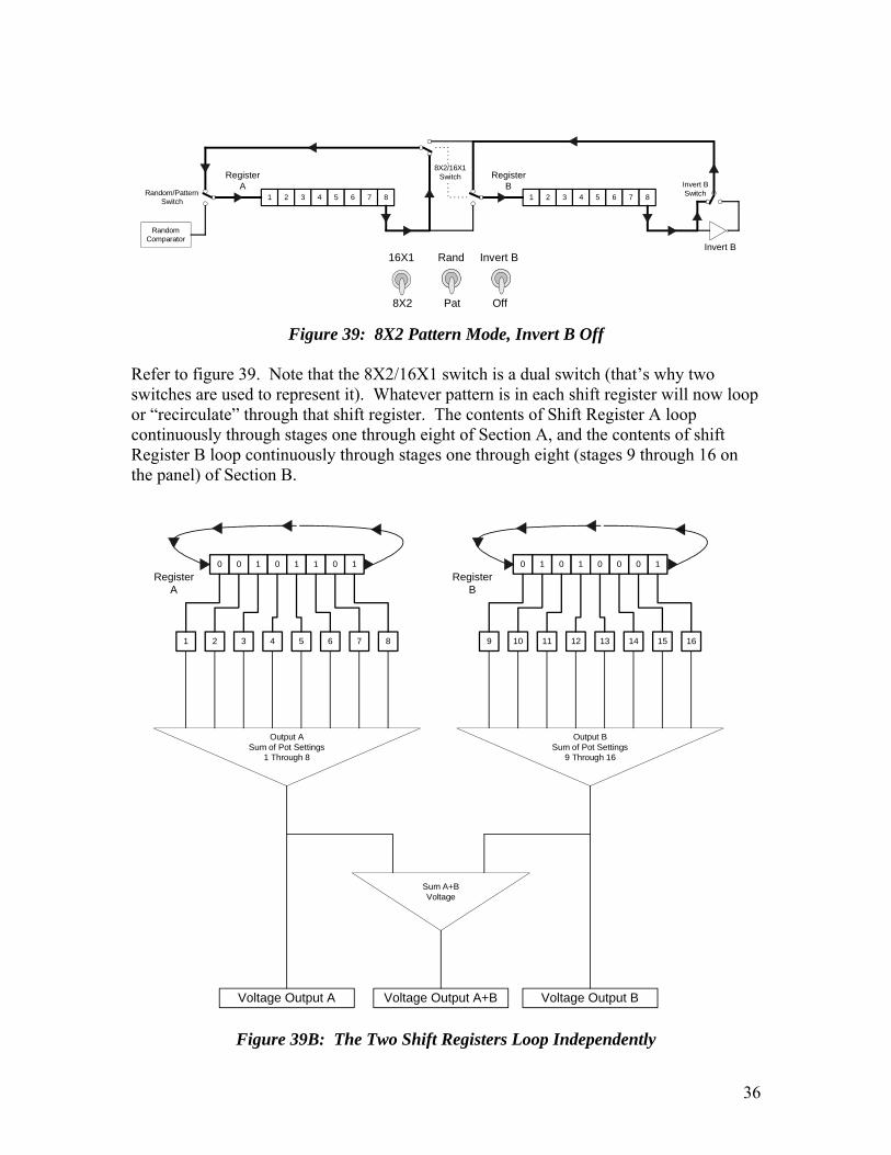
Refer to figure 39. Note that the 8X2/16X1 switch is a dual switch (that’s why two switches are used to represent it). Whatever pattern is in each shift register will now loop or “recirculate” through that shift register. The contents of Shift Register A loop continuously through stages one through eight of Section A, and the contents of shift Register B loop continuously through stages one through eight (stages 9 through 16 on the panel) of Section B.
0 0 1 0 1 1 0 1
1 2 3 4 5 6 7 8
0 1 0 1 0 0 0 1
9 10 11 12 13 14 15 16
RegisterA
RegisterB
Output ASum of Pot Settings
1 Through 8
Output BSum of Pot Settings
9 Through 16
Sum A+BVoltage
Voltage Output A Voltage Output A+B Voltage Output B
Figure 39B: The Two Shift Registers Loop Independently

37
Look at Figure 39B. Note how the voltage pattern of Shift Register A now will be an eight step pattern on Voltage Output A and the voltage pattern of Shift Register B will now be an eight step pattern on Voltage Output B. The A and B voltages are summed together to form Voltage Output A+B. Voltage Output A+B will also be an eight step pattern. The effect of summing the A and B output voltages is the same as summing the output of all the programming pots, which is keeping with the tradition of the original Klee Sequencer, except that model had only one sixteen bit shift register, not two eight bit shift registers.
That leads us to the discussion of the 16X1 Pattern Mode, with Invert B off.
1 2 3 4 5 6 7 8 1 2 3 4 5 6 7 8
RandomComparator
Invert B
RegisterA
RegisterB
8X2/16X1Switch
Random/PatternSwitch
Invert BSwitch
16X1
8X2
Rand
Pat
Invert B
Off
Figure 40: 16X1 Pattern Mode, Invert B Off
Refer to Figure 40. The only change we have made is to place the 8X2/16X1 switch in the 16X1 position. If you recall, the 8X2/16X1 switch is a dual switch, and, in this case, it now routes the last bit of Shift Register A to the input of Shift Register B. And, it routes the last bit of Shift Register B to the input of Shift Register A. We have just combined our two eight bit shift registers into one sixteen bit recirculating shift register. That means it will take sixteen clock cycles to move the pattern entirely through the shift registers before it begins again. Therefore, we now have a sixteen step sequence. This results in three unique sixteen step voltage patterns at our voltage outputs.
Because a sixteen bit pattern is “sliding past” our section A programming pots, those eight pots will produce a sixteen step pattern on Voltage Output A.
By the same token, a sixteen bit pattern is also rubbing up against our section B programming pots, so, again, we have a unique voltage pattern present on Voltage Output B.
Voltage patterns A and B are summed together to form Voltage Output A+B, giving us our third unique sixteen step voltage pattern.
This configuration is exactly the same configuration as the original Klee Sequencer, except now, instead of having only four programming pots on the fourth, eighth, twelfth and sixteenth shift register taps, we now have programming pots on all sixteen of the shift

38
register taps. The A+B output will be the most varied of the three patterns, because the voltage provided by all sixteen pots is added together. That makes it the trickiest output to program, but, at the same time, you will probably find it renders the most unique and “out of left field” patterns the Klee has to offer. This is the original “loose clay”.
0 0 1 0 1 1 0 1
1 2 3 4 5 6 7 8
0 1 0 1 0 0 0 1
9 10 11 12 13 14 15 16
RegisterA
RegisterB
Output ASum of Pot Settings
1 Through 8
Output BSum of Pot Settings
9 Through 16
Sum A+BVoltage
Voltage Output A Voltage Output A+B Voltage Output B
Figure 40B: The Two Shift Registers Loop as One 16 Bit Register
Next up, we get into the Random Pattern Mode. Before we talk about that, we should delve a bit into that largely ignored little portion of our block diagram – the Random Comparator.

39
InputComparator
RefLevel
RandomLevel
ExternalRandomSignal
0110001010111010110
Figure 41: The Random Comparator Function
Figure 41 illustrates the Random Comparator section. The Random Comparator function was inspired by Ken Stone’s exquisite Gated Comparator circuit. The comparator circuit on the input was derived directly from it. It provides a means to program the Klee Pattern randomly. The first Klee Sequencer used this as its only method of programming. The Random Comparator essentially uses a standard voltage comparator to derive a random stream of highs and lows (1’s and 0’s) from an external signal. This stream of data is then fed to Shift Register A when the Random/Pattern Switch is placed in the Random position.
The Random Comparator consists of the Reference Level Control, the Random Level Control, the Random Signal Input Connector, and an internal comparator circuit. When the external signal rises above the internally generated reference signal (as set by the Reference Level Control) a high or “1” state is generated. If the level of the randomsignal falls below the reference level, the output of the comparator is low or “0”.
Reference
Figure 42: One High Bit Generated From Random Signal
Adjusting the Reference level up or down increases or decreases the probability that a “1” will be generated at any given time. In Figure 42, we see the reference level is set high enough that our example random signal only generates a single “1”.

40
Reference
Figure 43: Three High Bits Generated From Random Signal
In Figure 43, the reference level is set to a lower level. With the same example random signal, three “1’s” are now created (the level rises above the reference signal on three separate occasions).
Reference
Figure 44: One High Bit Generated From Random Signal with Reduced Signal Level
Because any bipolar signal can be applied to the Random Input, some signals may be stronger than others. The Random Level control can be used to attenuate high signals applied to the input. It also serves to determine the probability of generating a “1” or a “0” with a particular signal. In Figure 44, the Reference Level is set to the same level as Figure 43, but the random signal has been reduced so that only one high bit is generated from the example input signal.
Shift Register A is an “exclusive club” when it comes to accepting a high or low input. Its membership criteria is that any signal on its input is allowed to be a member of the Shift Register A Bit Club only when the clock signal is rising.
The random comparator can generate thousands of “1’s” or “0’s”, but only a lucky few will actually make it through to the shift register. This situation creates a relationship between the clock frequency and the amount of fluctuation of the input signal, which is a further layer of pseudorandom behavior. In fact, the input signal need not be random at all – it can be a periodic wave from an LFO or VCO, but the pattern generated from the input will still have a level of pseudo-randomness to it; this pseudo-random relationship is a function of the frequency of the input signal versus the frequency of the clock. At some points the periodic wave may be high when the clock goes high, and other times it may not.

41
1 2 30 1 0 0 10
0
1
10
Clock is not rising, so nobits are allowed into Shift
Register A
Comparator
Shift Register A
Figure 45: No Bits Are Allowed In Because the Clock is Not Rising
Figure 45 illustrates what happens when the bit stream is applied to Shift Register A while the Clock is either high or low but not in that split second of rising. Shift Register A simply ignores what is happening at its “front door”.
1 2 30 1 0 0 10
Clock rises, allowing bitinto Shift Register A
Comparator
Shift Register A
0
Figure 46: A Single Bit Is Allowed In Because the Clock is Rising
Figure 46 shows that, when the clock pulses high, whatever bit is at its front door is allowed into the shift register. In this case, the lucky bit is “0”.
So what happens to the bit in the eighth position of Shift Register A? After all, the shift register can only hold eight bits.
Shift Register A Bit 8’s fate is determined by which mode the Klee is in. In the case of the 8X2 mode, Bit 8 is history – it flies off into space, never to be seen again. In the case of the 16X1 mode, Shift Register A Bit 8 gets a reprieve and “crosses over” to Shift

42
Register B. Shift Register B Bit 8, however, is a goner – it steps off the gangplank into oblivion.
Let’s look at the 8X2 Random Mode.
1 2 3 4 5 6 7 8 1 2 3 4 5 6 7 8
RandomComparator
Invert B
RegisterA
RegisterB
8X2/16X1Switch
Random/PatternSwitch
Invert BSwitch
16X1
8X2
Rand
Pat
Invert B
Off
Figure 47: 8X2 Random Mode
Figure 47 shows that the input to Shift Register A is now the random bit stream from the comparator. Bit 8 of Shift Register A is disconnected from the input of either shift register, so the data does not recirculate. Therefore, the voltage pattern generated by Shift Register A is a non-repeating random pattern with no fixed number of repeating steps.
Shift Register B is still recirculating – the output of Shift Register B is still connected to its input. So, Shift Register B will still generate a repeating eight step pattern.
The Voltage A+B Output will now be rather interesting – it will have the random non-repeating element of the Voltage A Output summed with the eight step repeating pattern of the Voltage B Output. The inference of that is the A+B output will be random, but with an underlying eight step pattern.
Up to this point, we’ve been discussing these modes in terms of the effect they will have on the voltage patterns generated. Remember that these Klee Patterns also effect what is happening on the Gate Bus. In this case, for example, it is possible to program a random gate bus pattern with a repeating voltage pattern, or vice-versa!
Of course, this not the same effect as operating in the 16X1 Random Mode. In that mode, there is no repeating pattern present.

43
1 2 3 4 5 6 7 8 1 2 3 4 5 6 7 8
RandomComparator
Invert B
RegisterA
RegisterB
8X2/16X1Switch
Random/PatternSwitch
Invert BSwitch
16X1
8X2
Rand
Pat
Invert B
Off
Figure 48: 16X1 Random Mode
Figure 48 illustrates why. In this mode, the output of Shift Register A is fed to the input of Shift Register B. The output of Shift Register B is disconnected from the input of Shift Register A, so no recirculation is possible. The result is that each shift register will sequentially shift the bits generated by the Random Comparator.
Therefore, the Voltage A output will be random and non-repeating, the Voltage B output will be random and non-repeating, and the Voltage A+B output will also be the summed value of these two non-repeating patterns. We now are generating three unique random voltage outputs.
The Invert B function has been, up to this point, quite ignored. In order to fully understand its effect, it was best to explore what happens when it is not used. We’ve covered all of the modes possible without resorting to it for further variation, so now’s the time to see what Invert B is all about.
So far, the maximum number of steps in a repeating Klee pattern has been sixteen. The Invert B function expands that number to a maximum of thirty two steps before a Klee Pattern repeats. It does it quite simply, but the effect is truly a wonderful thing to behold.
The Invert B function does just what the name implies – it inverts the bits exiting Shift Register B before they are recirculated. In Figure 48, it can be seen that the only mode the Invert B control has no effect is the 16X1 Random mode – that is the only mode where no recirculation path is present, so inverting the output of Shift Register B has no consequence.
Lets look at what effect inverting the bits as they’re recirculating has. Let’s use the example pattern 10011001.
If the pattern 10011001 is not inverted, it simply repeats as such:
100110011001100110011001100110011001100110011001100110011001100110011001
Inverting 10011001 creates its doppelganger opposite: 01100110. When recirculating, the original pattern 10011001 will alternate with the evil, inverted pattern 01100110.

44
Therefore, from this eight bit pattern, we have created a sixteen bit pattern:
1001100101100110
To see the true effect of what this involves, we’ll put the original, non-inverting pattern on the top line and the inverting pattern on the bottom line as follows:
100110010110011010011001011001101001100101100110100110010110011010011001100110011001100110011001100110011001100110011001100110011001100110011001
Oh, gee, that’s so exciting….
The effect may not look all that exciting, but it opens up the Klee Voltage and Gate Bus patterns like a can of worms. In fact, it will turn a sixteen bit pattern into a thirty two bit pattern. Let’s “top and bottom juxtapose” a repeating 16 bit pattern with it’s thirty two bit inverted derivation. Top line is the sixteen bit pattern, bottom line is the 32 bit pattern:
10110000111000111011000011100011101100001110001110110000111000111011000011100011010011110001110010110000111000110100111100011100
It is indeed a truly wonderful and quite musical way of introducing extended variation in a Klee Pattern.
Plodding on, we return to the 8X2 Pattern mode, only this time we have the Invert B switch set on.
1 2 3 4 5 6 7 8 1 2 3 4 5 6 7 8
RandomComparator
Invert B
RegisterA
RegisterB
8X2/16X1Switch
Random/PatternSwitch
Invert BSwitch
16X1
8X2
Rand
Pat
Invert B
Off
Figure 49: 8X2 Pattern Mode with Invert B On
Figure 49 shows that now the Invert B function is inverting the output of Shift Register B. Because each shift register is recirculating its own data, this has no effect on the data in Shift Register A – the inverted bit stream is being directed only to Shift Register B.

45
Our voltage patterns reflect that: Voltage A Out consists of an eight step repeating pattern while the Voltage B output consists of a sixteen step repeating pattern, thanks to the effect the Invert B function is having on Shift Register B.
Our two patterns are summed to create the Voltage A+B, but look what has happened: because the B Voltage Output is a sixteen step repeating pattern, Voltage A+B will also be a repeating sixteen step pattern. This gives us one unique eight step repeating pattern (Output A) and two repeating sixteen step patterns (outputs B and A+B)!
It gets juicier – take a look at Figure 50.
1 2 3 4 5 6 7 8 1 2 3 4 5 6 7 8
RandomComparator
Invert B
RegisterA
RegisterB
8X2/16X1Switch
Random/PatternSwitch
Invert BSwitch
16X1
8X2
Rand
Pat
Invert B
Off
Figure 50: 16X1 Pattern Mode with Invert B On
Figure 50 shows us that, while in the 16X1 pattern mode, the Invert B function inverts the entire 16 bit Klee pattern. Note that the output of the inverter feeds the input of Shift Register A. This inverted sixteen bit pattern renders a 32 step voltage pattern on each of our outputs!
Voltage Output A delivers the unique 32 step pattern generated by the Section A programming pots, Voltage output B delivers the unique 32 step pattern generated by the Section B programming pots, and, of course, output A+B delivers the unique 32 step pattern generated by adding the A and B patterns together.
This leads us to the final, un-discussed mode mentioned in Table 5, lo these many pages ago.
Finally…..
We heard that. If you’ll recall, it was mentioned that in the 16X1 Random Mode, the Invert B function would have no effect. This is because, in order for Invert B to do its thing, its output must be recirculated by a shift register. In the case of the 8X2 Random Mode, this does happen.
Figure 51 illustrates the path the signals take when in the 8X2 Random Mode with the Invert B function set to on.

46
1 2 3 4 5 6 7 8 1 2 3 4 5 6 7 8
RandomComparator
Invert B
RegisterA
RegisterB
8X2/16X1Switch
Random/PatternSwitch
Invert BSwitch
16X1
8X2
Rand
Pat
Invert B
Off
Figure 50: 8X2 Random Mode with Invert B On
Register A is fed the random bits generated in the Random Comparator. Register B is recirculating its eight bit pattern. With the Invert B function on, this eight bit pattern is transformed into a sixteen step voltage pattern.
The A Voltage Output delivers the non-repeating random pattern generated by Section A. The B Voltage Output delivers the repeating sixteen step pattern generated in Section B with the assistance of the Invert B function. Like the 8X2 Random mode with no inversion of the output of Shift Register B, the A+B Voltage Output consists of the summation of the non-repeating random pattern with the repeating pattern, only this time the summed repeating pattern is a sixteen step pattern instead of an eight step pattern.