getting to know autocadautocad 2008 autocad 2008 or by choosing start all programs autodesk autocad...
TRANSCRIPT

CHAPTER 1
Getting to KnowAutoCAD� Opening a new drawing
� Getting familiar with the AutoCAD and AutoCAD LTgraphics windows
� Modifying the display
� Displaying and arranging toolbars
26531ch01.qxd 3/30/07 4:59 PM Page 1
COPYRIG
HTED M
ATERIAL

Your introduction to AutoCAD and AutoCAD LT begins with a tour of theuser interface of the two programs. In this chapter, you’ll also learn howto use some tools that help you control the interface’s appearance andhow to find and start commands. For the material covered in this chap-
ter, the two applications are almost identical in appearance. Therefore, as youtour AutoCAD, I’ll point out any differences between AutoCAD and AutoCAD LT.In general, LT is a 2D program, so it doesn’t have most of the 3D features thatcome with AutoCAD, such as solids modeling and rendering. The AutoLISP pro-gramming language found in AutoCAD is also absent from LT. The other differ-ences are minor. As mentioned in this book’s introduction, when I say AutoCAD,I mean both AutoCAD and AutoCAD LT. I’ll also refer to AutoCAD LT as LTthroughout this chapter and the rest of the book to specifically refer to that ver-sion. Starting AutoCAD is the first task at hand.
Starting AutoCADIf you installed AutoCAD using the default settings for the location of the pro-gram files, start the program by choosing Start ➣ Programs ➣ Autodesk ➣
AutoCAD 2008 ➣ AutoCAD 2008 or by choosing Start ➣ All Programs ➣
Autodesk ➣ AutoCAD LT 2008 ➣ AutoCAD LT 2008, depending on your pro-gram. (This command path might vary depending on the Windows scheme youare using.) If you customized your installation, find and click the AutoCAD 2008icon or the AutoCAD LT 2008 icon on your desktop.
Exploring the New Features WorkshopThe New Features Workshop dialog welcome screen opens when you first startAutoCAD and leads to several animated demonstrations and explanations of thenew features included in the latest release of AutoCAD (see Figure 1.1). This is aquick and easy way to see how AutoCAD 2008 has improved over AutoCAD 2007and which tools you can use to augment any skills you already have. ChoosingMaybe Later on the left side of the dialog box causes it to reappear every time youstart AutoCAD; choosing the No, Don’t Show This to Me Again option dismissesthe dialog box indefinitely. You must then access the New Features Workshopthrough the Help menu in the menu bar at the top of the AutoCAD user interface.
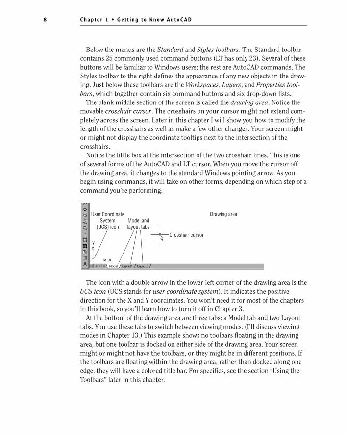
Selecting the Yes radio button on the left side of the dialog box opens the NewFeatures Workshop dialog box (see Figure 1.2). Here, you navigate and select thefeature you want to investigate in the left pane and observe the selection in theright pane. The drop-down list in the upper-left corner provides access to theNew Features Workshops for other Autodesk products installed on your system.
C h a p t e r 1 • G e t t i n g t o K n o w A u t o C A D2
26531ch01.qxd 3/30/07 4:59 PM Page 2
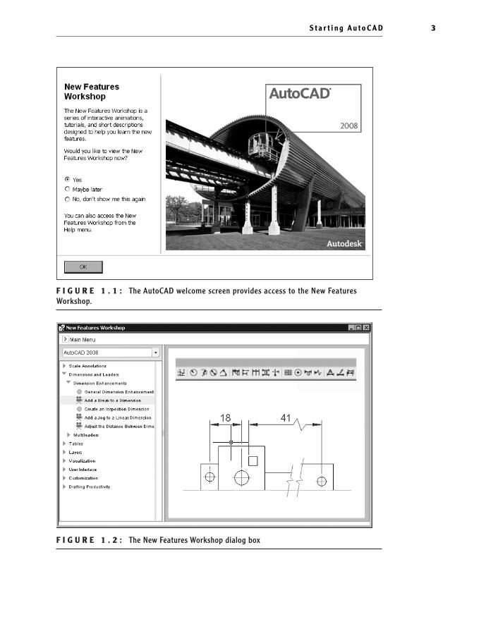
F I G U R E 1 . 1 : The AutoCAD welcome screen provides access to the New Features Workshop.
F I G U R E 1 . 2 : The New Features Workshop dialog box
S t a r t i n g A u t o C A D 3
26531ch01.qxd 3/30/07 4:59 PM Page 3

The Customer Involvement ProgramNearly all the latest releases of Autodesk products include the opportunity toparticipate in the customer involvement program (CIP). The CIP is designed tocollect nonpersonal information about your Autodesk products and computersystem to help the product programmers and developers design software thatbest meets their customers’ needs. If you haven’t yet agreed or disagreed to par-ticipate, when you first start AutoCAD, you might be prompted to join with theCustomer Involvement Program dialog box.
Participation is strictly voluntary, and if you choose to participate, AutoCADwill periodically send a small file to Autodesk containing information such asyour software name and version, the commands you use, and your system con-figuration information. An Internet connection is required, and you must ensurethat your firewall settings don’t prevent the information from being transmitted.
Exploring the AutoCAD User InterfaceAfter bypassing the initial dialog boxes that AutoCAD provides, the program opensto display the AutoCAD user interface, also called the graphics window. AutoCADprovides many methods for creating and editing objects, changing the view of adrawing, or executing AutoCAD file maintenance or other utilities. In LT, yourscreen looks similar to Figure 1.3. For AutoCAD, your monitor displays one ofthree workspaces: the AutoCAD Classic workspace (also similar to Figure 1.3); the3D Modeling workspace (see Figure 1.4); or the 2D Drafting & Annotation work-space, which is similar to the AutoCAD Classic workspace. You’ll be using a varia-tion of the AutoCAD Classic workspace for the first 14 chapters in this book. In thefinal two chapters, you’ll switch to the 3D Modeling workspace, but for now, youneed to get your AutoCAD user interface to look like Figure 1.3.
N O T E The figures and graphics is this book show the drawing area ofthe AutoCAD user interface with a white background, but the default, and pre-ferred, method is to use a black background to reduce eyestrain. The colorchoice in the book is simply for readability.
C h a p t e r 1 • G e t t i n g t o K n o w A u t o C A D4
�
AutoCAD and LToffer numerous dia-log boxes with vari-ous combinations ofbuttons and textboxes.You’ll learntheir many functionsas you progressthrough the book.
26531ch01.qxd 3/30/07 4:59 PM Page 4

F I G U R E 1 . 3 : The AutoCAD graphics window using the AutoCAD Classic workspace
F I G U R E 1 . 4 : The AutoCAD graphics window using the 3D Modeling workspace
Title barMenu barStandard toolbarWorkspaces toolbarDraw toolbar
Layers toolbar Properties toolbarStyles toolbar
InfoCenterCommunications Center
FavoritesTool palettes
Modify toolbar
Drawing area
User CoordinateSystem (UCS) icon
Model andlayout tabs
Commandwindow
Statusbar
S t a r t i n g A u t o C A D 5
26531ch01.qxd 3/30/07 4:59 PM Page 5

The toolbars on your screen might not be in the same places as they are shownhere. Later in this chapter, you’ll see how to move the toolbars, display and placenew toolbars, and suppress the toolbars. If your screen looks like Figure 1.4 orisn’t at all like Figure 1.3, you need to make a few changes:
1. Click the drop-down arrow in the Workspaces toolbar, and choose Auto-CAD Classic. Alternately, you can choose Tools ➣ Workspaces ➣
AutoCAD Classic. (If AutoCAD Classic already has a check in the boxnext to it or if you are using LT, this step is unnecessary.)
2. By default, the AutoCAD Classic workspace displays the tool paletteson the screen. If the palettes are displayed, you need to turn them offfor now by clicking the X in the top-right corner or by choosingTools ➣ Palettes ➣ Tool Palettes from the menu bar. Your workspacemight have different toolbars and palettes displayed than thoseshown in Figure 1.5. If other palettes are still visible, click the X inthe upper-right or upper-left corner of each palette to close it.
F I G U R E 1 . 5 : The tool palettes
C h a p t e r 1 • G e t t i n g t o K n o w A u t o C A D6
26531ch01.qxd 3/30/07 4:59 PM Page 6

3. The large area in the middle of the screen is called the drawing area. Itmight need adjusting. Choose View ➣ Visual Styles ➣ 2D Wireframe.
4. Choose View ➣ 3D Views ➣ Plan View ➣ World UCS. If dots appear inthe drawing area, the grid is turned on.
5. Move the cursor to the status bar at the bottom of the screen, andclick the Grid readout button so it’s in the off (unpushed) position. Besure all the other readout buttons except Model are in their off(unpushed) positions.
Your screen should look close enough to Figure 1.3 to continue. You’ll arrangethe toolbars the way you need them a little later.
Introducing the AutoCAD Graphics WindowAt the top of the graphics window sit the title bar, the menu bar, and three toolbars.You might have more or less than three toolbars; if so, you’ll change that soon.
The title bar is analogous to the title bar in any Windows program. It containsthe program name (AutoCAD or AutoCAD LT) and the title of the current draw-ing with its path, as long as any drawing other than the default Drawingn.dwg isopen. Below the title bar is the menu bar, where you’ll see the drop-downmenus. Among the drop-down menus, File, Edit, Window, and Help are standardWindows menus (meaning that they appear on Windows-compliant applica-tions). These Windows menus also contain a few commands specific to AutoCAD.The rest of the menus contain AutoCAD-specific functions.
To the far right of the menus are the InfoCenter, Communications Center, andFavorites buttons. You can enter a question in the field to the left of the Info-Center button to quickly access information from the Help system through theInfoCenter’s drop-down panel. With the Communications Center you can deter-mine what type of information, such as software updates, product support, orRSS feeds, Autodesk sends directly to your system.
Title bar Menu barCommunications
CenterInfoCenter Favorites
Workspaces toolbar Standard toolbar Layers toolbar Properties toolbar Styles toolbar
I n t r o d u c i n g t h e A u t o C A D G r a p h i c s Wi n d o w 7
�
The title bar andmenu bar at the topof the LT screen areidentical to those inAutoCAD except thatAutoCAD LT appearsin the title bar ratherthan AutoCAD.
�
LT users can skipstep 3 and move onto step 4.
26531ch01.qxd 3/30/07 4:59 PM Page 7
Below the menus are the Standard and Styles toolbars. The Standard toolbarcontains 25 commonly used command buttons (LT has only 23). Several of thesebuttons will be familiar to Windows users; the rest are AutoCAD commands. TheStyles toolbar to the right defines the appearance of any new objects in the draw-ing. Just below these toolbars are the Workspaces, Layers, and Properties tool-bars, which together contain six command buttons and six drop-down lists.
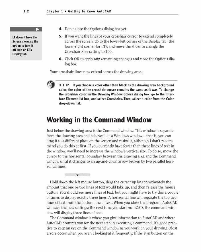
The blank middle section of the screen is called the drawing area. Notice themovable crosshair cursor. The crosshairs on your cursor might not extend com-pletely across the screen. Later in this chapter I will show you how to modify thelength of the crosshairs as well as make a few other changes. Your screen mightor might not display the coordinate tooltips next to the intersection of thecrosshairs.
Notice the little box at the intersection of the two crosshair lines. This is oneof several forms of the AutoCAD and LT cursor. When you move the cursor offthe drawing area, it changes to the standard Windows pointing arrow. As youbegin using commands, it will take on other forms, depending on which step of acommand you’re performing.
The icon with a double arrow in the lower-left corner of the drawing area is theUCS icon (UCS stands for user coordinate system). It indicates the positivedirection for the X and Y coordinates. You won’t need it for most of the chaptersin this book, so you’ll learn how to turn it off in Chapter 3.
At the bottom of the drawing area are three tabs: a Model tab and two Layouttabs. You use these tabs to switch between viewing modes. (I’ll discuss viewingmodes in Chapter 13.) This example shows no toolbars floating in the drawingarea, but one toolbar is docked on either side of the drawing area. Your screenmight or might not have the toolbars, or they might be in different positions. Ifthe toolbars are floating within the drawing area, rather than docked along oneedge, they will have a colored title bar. For specifics, see the section “Using theToolbars” later in this chapter.
Drawing areaUser CoordinateSystem
(UCS) iconModel andlayout tabs
Crosshair cursor
C h a p t e r 1 • G e t t i n g t o K n o w A u t o C A D8
26531ch01.qxd 3/30/07 4:59 PM Page 8

Below the drawing area is the Command window.
When you enter commands, rather than using the menus or buttons, theCommand window is where you tell the program what to do and where the pro-gram tells you what’s happening. It’s an important area, and you’ll need to learnhow it works in detail. Two lines of text should be visible. You’ll learn how toincrease the number of visible lines later in this chapter in the section “Workingin the Command Window.”
Below the Command window is the status bar.
On the left end of the status bar, you’ll see a coordinate readout window. Inthe middle are 10 readout buttons (LT has only 9) that indicate various drawingmodes. It’s important to learn about the coordinate system and most of thesedrawing aids (Snap, Grid, Ortho, and Osnap) early on as you learn to draw inAutoCAD or LT. They will help you create neat and accurate drawings. Polar andOtrack are advanced drawing tools and will be introduced in Chapter 5. Ducsstands for Dynamic User Coordinate System; it’s used in 3D drawings. Dyn is anoff/on toggle that activates or suppresses the dynamic display of informationnext to the crosshair cursor when it’s in the drawing area. For now, keep it inthe off (unpushed) mode. Lwt (which stands for lineweight) will be discussed inChapter 14. The Model button is an advanced aid that I’ll cover in Chapter 13. Atthe far right of the status bar are tools for controlling the appearance of annota-tion objects in AutoCAD. The padlock icon controls which types of toolbars andwindows are locked in their current positions on the screen. Leave it in theunlocked mode for now.
This has been a quick introduction to the various parts of the graphics win-dow. I didn’t mention a couple of items that might be visible on your screen. Youmight have scroll bars below and to the right of the drawing area; although thesecan be useful, they can take up precious space in the drawing area. They won’t beof any use while working your way through this book, so I suggest you removethem for now.
To temporarily remove these features, follow these steps:
1. Choose Tools ➣ Options to open the Options dialog box (shown inFigure 1.6). It has 10 tabs (LT has only 8) across the top that act liketabs on file folders.
I n t r o d u c i n g t h e A u t o C A D G r a p h i c s Wi n d o w 9
26531ch01.qxd 3/30/07 4:59 PM Page 9

F I G U R E 1 . 6 : The Options dialog box
2. Click the Display tab, which is shown in Figure 1.7. Focus on theWindow Elements section. If scroll bars are visible on the lower andright edges of the drawing area, the Display Scroll Bars In DrawingWindow check box will be selected.
F I G U R E 1 . 7 : The Options dialog box open at the Display tab
C h a p t e r 1 • G e t t i n g t o K n o w A u t o C A D1 0
26531ch01.qxd 3/30/07 4:59 PM Page 10

3. Click the check box to turn off the scroll bars. Also be sure the checkbox for Display Screen Menu is not selected. Don’t click the OK but-ton yet.
Another display setting that you might want to change at this point controlsthe color of the cursor and the drawing area background. The illustrations inthis book show a white background and black crosshair cursor, but you’re proba-bly seeing the AutoCAD default, which features a black background and a whitecrosshair cursor. If you want to change the colors, follow these steps:
1. In the Window Elements area of the Display tab, click the Colors but-ton to open the Drawing Window Colors dialog box (see Figure 1.8).In the upper-left corner of the dialog box, in the Context list box, 2DModel Space should be selected. If it’s not, select it.
F I G U R E 1 . 8 : The Drawing Window Colors dialog box
2. Move to the Color drop-down list, which is in the upper-right corner.If your drawing area background is currently white, a square followedby the word White is displayed. Open the Color drop-down list, andselect Black (or the background color you want). The drawing areawill now be that color, and the cursor color will change to white, asshown in the Preview window below.
3. Click the Apply & Close button to close the Drawing Window Colorsdialog box. The background and cursor colors change.
I n t r o d u c i n g t h e A u t o C A D G r a p h i c s Wi n d o w 1 1
26531ch01.qxd 3/30/07 4:59 PM Page 11
4. Don’t close the Options dialog box yet.
5. If you want the lines of your crosshair cursor to extend completelyacross the screen, go to the lower-left corner of the Display tab (thelower-right corner for LT), and move the slider to change theCrosshair Size setting to 100.
6. Click OK to apply any remaining changes and close the Options dia-log box.
Your crosshair lines now extend across the drawing area.
T I P If you choose a color other than black as the drawing area backgroundcolor, the color of the crosshair cursor remains the same as it was. To changethe crosshair color, in the Drawing Window Colors dialog box, go to the Inter-face Element list box, and select Crosshairs. Then, select a color from the Colordrop-down list.
Working in the Command WindowJust below the drawing area is the Command window. This window is separatefrom the drawing area and behaves like a Windows window—that is, you candrag it to a different place on the screen and resize it, although I don’t recom-mend you do this at first. If you currently have fewer than three lines of text inthe window, you’ll need to increase the window’s vertical size. To do so, move thecursor to the horizontal boundary between the drawing area and the Commandwindow until it changes to an up-and-down arrow broken by two parallel hori-zontal lines.
Hold down the left mouse button, drag the cursor up by approximately theamount that one or two lines of text would take up, and then release the mousebutton. You should see more lines of text, but you might have to try this a coupleof times to display exactly three lines. A horizontal line will separate the top twolines of text from the bottom line of text. When you close the program, AutoCADwill save the new settings; the next time you start AutoCAD, the command win-dow will display three lines of text.
The Command window is where you give information to AutoCAD and whereAutoCAD prompts you for the next step in executing a command. It’s good prac-tice to keep an eye on the Command window as you work on your drawing. Mosterrors occur when you aren’t looking at it frequently. If the Dyn button on the
C h a p t e r 1 • G e t t i n g t o K n o w A u t o C A D1 2
�
LT doesn’t have theScreen menu, so theoption to turn it off isn’t on LT’sDisplay tab.
26531ch01.qxd 3/30/07 4:59 PM Page 12

status bar is in the on position, some of the information in the Command win-dow will appear in the drawing area next to the cursor. I’ll cover this featurewhen you start drawing.
Before you begin to draw, take a close look at the menus, toolbars, and key-board controls.
N O T E In many cases, you can start AutoCAD commands in a number ofways: from drop-down menus, from the toolbars, from the Command window,and from menus that appear when you right-click. When you get used todrawing with AutoCAD, you’ll learn some shortcuts that start commandsquickly, and you’ll find the way that is most comfortable for you.
Using the Drop-Down MenusThe left end of the menu bar, just below the title bar (see Figure 1.3 earlier in thischapter), consists of an icon and 11 (12 if you have the Express Tools installed)words. Click any of these to display a drop-down menu. The icon and the File andEdit menus are included with all Windows-compliant applications, although theyare somewhat customized to work with AutoCAD. The drop-down menu associ-ated with the icon contains commands to control the appearance and position ofthe drawing area.
Commands in the File menu are for opening and saving new and existing draw-ing files, printing, exporting files to another application, choosing basic utilityoptions, and exiting the application. The Edit menu contains the Undo and Redocommands, the Cut and Paste tools, and options for creating links between Auto-CAD files and other files. The Help menu works like most Windows Help menusand contains a couple of AutoCAD-specific entries as well, including some onlineresources and a link to the New Features Workshop.
The other eight (or nine) menus contain the most often used AutoCAD com-mands. You’ll find that if you master the logic of how the commands are orga-nized by menu, you can quickly find the command you want. Here is a shortdescription of each of the other AutoCAD drop-down menus:
View Contains tools for controlling the display of your drawing file.
Insert Contains commands for placing drawings and images or parts of theminside other drawings.
Format Contains commands for setting up the general parameters for a newdrawing or changing the entities in a current drawing.
U s i n g t h e D r o p - D o w n M e n u s 1 3
26531ch01.qxd 3/30/07 4:59 PM Page 13
Tools Contains special tools for use while you’re working on the current draw-ing, such as those for finding the length of a line or for running a special macro.
Draw Contains commands for creating new objects (such as lines or circles) onthe screen.
Dimension Contains commands for dimensioning and annotating a drawing.
Modify Contains commands for changing existing objects in the drawing.
Window Contains commands for displaying currently open drawing windowsand lists currently open drawing files.
Express Contains a library of productivity tools that cover a wide range ofAutoCAD functions. Express Tools are widely used but unsupported directly byAutodesk. They might or might not be installed on your computer.
Using the ToolbarsNow look at the toolbars on your screen. You’ll have two to five toolbars in oneor two rows at the top and a couple more on the right and/or left sides of thedrawing area. Just below the drop-down menus is the most extensive of the tool-bars—the Standard toolbar.
The icons on the AutoCAD toolbars look like flat images and don’t appear asraised buttons until you point to them. The Standard toolbar has 25 icons, andthey are arranged into 7 logical groups. The icons on the left half of the Standardtoolbar are mostly for commands used in all Windows-compatible applications,so you might be familiar with them. The icons on the right half of the Standardtoolbar are AutoCAD commands that you use during your regular drawing activ-ities. You use these commands to take care of a number of tasks, including thefollowing:
� Changing the view of the drawing on the screen
� Changing the properties of an object, such as color or linetype
� Borrowing parts of an unopened drawing to use in your currentdrawing
� Displaying a set of palettes that contain objects you can use in yourdrawing
C h a p t e r 1 • G e t t i n g t o K n o w A u t o C A D1 4
�
LT has only 23Standard toolbarbuttons. It’s missingthe Sheet SetManager and BlockEditor buttonsbecause LT doesn’toffer these features.
26531ch01.qxd 3/30/07 4:59 PM Page 14

Accessing the Toolbar Fly-Out MenusNotice that one icon on the Standard toolbar has a little triangular arrow in thelower-right corner. This arrow indicates that clicking this icon displays morethan one command. Follow these steps to see how this special icon works:
1. Move the cursor to the Standard toolbar, and point to the icon thathas a magnifying glass with a rectangle in it.
2. Rest the arrow on the button for a moment without clicking. A smallwindow opens just below it, displaying the command the button rep-resents. In this case, the window should say Zoom Window. This is atool tip—all buttons have them. Notice the small arrow in the lower-right corner of the icon. This is the multiple-command arrow men-tioned earlier.
3. Place the arrow cursor on the button, and hold down the left mousebutton. A column of nine buttons opens vertically below the originalbutton (see Figure 1.9). The top button in the column is a duplicateof the button you clicked. This column of buttons is called a toolbarfly-out menu. In this example, you’re working with the Zoom toolbarfly-out menu.
F I G U R E 1 . 9 : Toolbar fly-out menu
4. While still holding down the mouse button, drag the arrow down overeach button until you get to the one that has a magnifying glass with apiece of white paper on it. Hold the arrow there until you see thetooltip. It should say Zoom All. Now release the mouse button. Thefly-out menu disappears, and AutoCAD executes the Zoom All com-mand. Look in the Command window at the bottom of the screen.
U s i n g t h e To o l b a r s 1 5
�
The Zoom All com-mand changes theview of your drawingto include special pre-set parameters.You’lllook at this commandin Chapter 3.
26531ch01.qxd 3/30/07 4:59 PM Page 15

At the end of the top line of text is _all. This tells you that you haveused the All option of the Zoom command. This fly-out menu iscalled the Zoom fly-out menu because it contains tools for changingviews of the drawing, or “zooming around in the drawing.”
5. Look at the Standard toolbar where the Zoom Window button waspreviously. Notice that the Zoom All button has replaced it.
T I P On a toolbar fly-out menu, the button you select replaces the buttonthat was on the toolbar. This arrangement is handy if you’re going to be usingthe same command several times, because the button for the command isreadily available and you don’t have to open the fly-out menu to select itagain. The order of the fly-out menu buttons remains the same, so when youopen the Zoom fly-out menu again, the Zoom Window button will be at thetop of the list. You’ll need to become familiar with any fly-out menu buttonsyou use, because the last one used becomes the representative button on thetoolbar.
The behavior of the Zoom fly-out menu on the Standard toolbar is the same asthe behavior of fly-out menus in general.
N O T E Whenever you start AutoCAD or LT for a new drawing session,the toolbars are reset and contain the original fly-out menu buttons.
The toolbar fly-out menus are regular toolbars that have been attached toanother toolbar. AutoCAD has 37 toolbars in all, but only a few have fly-outmenus—the Zoom fly-out menu I just discussed and the Insert fly-out menu onthe Draw toolbar, for example. You can display the Zoom and Insert fly-outmenus as regular toolbars, independent of the Standard and Draw toolbars.
Displaying and Arranging ToolbarsIn this section, I’ll use the Zoom toolbar to show you some ways you can controland manipulate toolbars. Follow these steps:
1. Be sure the padlock icon in the lower-right corner of your screen is inunlocked mode. Then, right-click any toolbar button on the screen toopen the Toolbars menu (see Figure 1.10).
C h a p t e r 1 • G e t t i n g t o K n o w A u t o C A D1 6
�
LT has 24 toolbarscompared withAutoCAD’s 37. Theadditional toolbars inAutoCAD are almostall for 3D and ren-dering tools.
26531ch01.qxd 3/30/07 4:59 PM Page 16

F I G U R E 1 . 1 0 : The Toolbars menu
2. If you don’t see Zoom near the bottom of the list, you should have adown arrow there. Use it to scroll down, if necessary, and then clickZoom to display the Zoom toolbar in the form of a floating box in thedrawing area.
Notice that the Zoom toolbar now has a title bar. Toolbars that arepositioned on the drawing area are called floating toolbars. They havetitle bars; and by placing the cursor on the title bar and holding downthe left mouse button, you can drag the toolbar around the screen.Try this with the Zoom toolbar.
3. Drag the Zoom toolbar to the right side of the screen. You’ll noticethat as you drag it, the toolbar stays put, and you’re dragging a rec-tangle of the same size as the toolbar (see Figure 1.11). As you dragthe rectangle to the right of the drawing area and begin to move itoff the drawing area onto the right side of the screen, the rectanglebecomes taller and thinner.
U s i n g t h e To o l b a r s 1 7
26531ch01.qxd 3/30/07 4:59 PM Page 17

F I G U R E 1 . 1 1 : Dragging the Zoom toolbar
4. Once the rectangle has changed shape, release the left mouse button.The rectangle changes to the Zoom toolbar, which is now positionedoff the drawing area without its title bar.
This procedure is called docking a toolbar. Notice how the Standard and othertoolbars at the top of the drawing area have no title bars—they are docked.
Continue with these steps:
1. Drag the Zoom toolbar back onto the drawing area, using the grabbars at the top of the toolbar. You can easily change the shape of anyfloating toolbar by dragging its edge. Let’s change the shape of thistoolbar.
2. Move the cursor to the far-right edge of the Zoom toolbar until thecrosshair cursor changes to a two-way arrow.
C h a p t e r 1 • G e t t i n g t o K n o w A u t o C A D1 8
�
Grab bars are the twolines at the left end ofa horizontal toolbaror at the top of a ver-tical one. They repre-sent the one place tograb a docked toolbarto move it.You canalso change a dockedtoolbar into a float-ing toolbar by double-clicking its grab bars.
26531ch01.qxd 3/30/07 4:59 PM Page 18

Hold down the left mouse button with the cursor on the right edge ofthe toolbar, and drag the arrow to the left until the rectangle changesshape. Release the mouse button.
You can reshape and reposition each floating toolbar to fit on thedrawing area just as you want it. You won’t need the Zoom toolbarjust now, so you’ll remove it.
3. Move the cursor to the title bar, and click the box with an X in it toclose the Zoom toolbar.
Floating toolbars don’t affect the size of the drawing area, but they cover yourdrawing. Each row or column of docked toolbars takes up space that would other-wise be drawing area. You have to decide how many docked and floating toolbarsyou need on the screen at a time. A good way to start is to leave the Standard, Lay-ers, and Properties toolbars docked on the top of the screen and the Draw andModify toolbars docked on the left side of the screen.
If your toolbars are positioned as shown in Figure 1.12, continue with the nextsection. If these toolbars are in another location on the drawing area or not visible,try the steps you used in this section to dock them on the top and left sides of thedrawing area. If the toolbars aren’t visible, right-click any visible toolbar button,and choose the toolbar you need. Then, drag the toolbar to the left side or top ofthe drawing area to dock it. Here are the positions I recommend for the five tool-bars you should dock on your screen:
� At the top, just under the menu bar, dock the Standard toolbar.
� Below that, on the left side, dock the Layers toolbar.
� To the right of the Layers toolbar, dock the Properties toolbar.
� On the left side, dock the Draw toolbar.
� Next to the Draw toolbar, dock the Modify toolbar.
U s i n g t h e To o l b a r s 1 9
26531ch01.qxd 3/30/07 4:59 PM Page 19

F I G U R E 1 . 1 2 : The AutoCAD user interface with five toolbars docked on the top and leftsides of the drawing area
This arrangement of the toolbars will be convenient because you’ll often usecommands on these five toolbars. When you need other toolbars temporarily,you can use the Toolbars menu to display them in the drawing area and let themfloat. If you have any other toolbars docked on the screen, use their grab bars todrag them onto the screen. Then, click the Xs in their title bars to close them.Here is a partial list of toolbars that you might have on your screen that need tobe turned off:
� Display Order toolbar
� Styles toolbar
� Workspaces toolbar
C h a p t e r 1 • G e t t i n g t o K n o w A u t o C A D2 0
26531ch01.qxd 3/30/07 4:59 PM Page 20

Customizing ToolbarsYou can customize each toolbar, and you can build your own custom toolbars todisplay only the buttons you use frequently. You can even design your own but-tons for commands that aren’t already represented by buttons on the toolbars.These activities are for more advanced users, however, and aren’t covered in thisbook. To find out more about how to customize toolbars, see Mastering Auto-CAD 2008 and AutoCAD LT 2008 by George Omura (Wiley, 2007).
WorkspacesNow that you have your screen set up to look like Figure 1.3, you are ready toproceed through the book. I’ll direct you to display additional toolbars as needed.For now, though, save this setup as a new workspace because it’s a variation ofthe AutoCAD Classic or LT workspace that comes with the program. Followthese steps:
1. Choose Tools ➣ Workspaces ➣ Save Current As. This opens the SaveWorkspace dialog box (see Figure 1.13).
F I G U R E 1 . 1 3 : The Save Workspace dialog box
2. Enter 2D Drawing, and click Save. The computer works for a whileand then returns you to your workspace. The new 2D Drawing work-space setup will remain as it now is until you change it or until youselect a different workspace.
3. Right-click any toolbar, and click the Workspaces entry in the Tool-bars list; you’ll see the 2D Drawing workspace displayed in the Work-spaces toolbar below 2D Drafting & Annotation, 3D Modeling, andAutoCAD Classic (see Figure 1.14). Later in this book, AutoCADusers will switch to the 3D Modeling workspace and make a fewadjustments to it.
U s i n g t h e To o l b a r s 2 1
26531ch01.qxd 3/30/07 4:59 PM Page 21

F I G U R E 1 . 1 4 : The Workspaces menu
4. Close the Workspaces toolbar.
When you make changes to the new workspace—by adding a toolbar or chang-ing the background color of the drawing area—you can easily update the 2DDrawing workspace to accommodate those changes. Follow steps 1 and 2 previ-ously, naming the workspace again to 2D Drawing. You’ll get a warning windowtelling you that a workspace by that name already exists and asking you whetheryou want the new arrangement to replace the old one. Click Yes.
Using the KeyboardThe keyboard is an important tool for entering data and commands. If you’re agood typist, you can gain speed in working with AutoCAD by learning how toenter commands from the keyboard. AutoCAD provides what are called aliaskeys—single keys or key combinations that start any of several often used com-mands. You can add more or change the existing aliases as you get more familiarwith the program.
In addition to the alias keys, you can use several of the F keys (function keys)on the top row of the keyboard as two-way or three-way toggles (switches) toturn AutoCAD functions on and off. Although buttons on the screen duplicatethese functions (Snap, Grid, and so on), it’s sometimes faster to use the F keys.
Finally, you can activate commands on the drop-down menus from the key-board, rather than by using the mouse. If you press the Alt key, an underlinedletter, called a hot key, appears on each menu. Pressing the key for the under-lined letter activates the menu. Each command on the menu also has a hot key.Once you activate the menu with the hot-key combination, you can enter theunderlined letter of these commands. For a few commands, this method can bethe fastest way to start them and to select options.
C h a p t e r 1 • G e t t i n g t o K n o w A u t o C A D2 2
26531ch01.qxd 3/30/07 4:59 PM Page 22

While working in AutoCAD, you’ll need to enter a lot of data, such as dimen-sions and construction notes; answer questions with “yes” or “no”; and use thearrow keys. You’ll use the keyboard constantly. It might help to get into thehabit of keeping your left hand on the keyboard and your right hand on themouse if you’re right-handed, or the other way around if you’re left-handed.
Using the MouseYour mouse most likely has two buttons and a scroll wheel. So far in this chap-ter, you have used the left mouse button for choosing menus, commands, oroptions or for holding down the button and dragging a menu, toolbar, or win-dow. The left mouse button is the one you’ll be using most often, but you’ll alsobe using the right mouse button.
While drawing, you’ll use the right mouse button for the following threeoperations:
� To display a menu containing options relevant to the particular stepyou’re in at the moment
� To use in combination with the Shift or Ctrl key to display a menucontaining special drawing aids called object snaps (see Chapter 10)
� To display a menu of toolbars when the pointer is on any icon of atoolbar that is currently open
If you have a three-button mouse, the middle button is usually programmed todisplay the Object Snap menu, instead of using the right button with the Shiftkey. If you have a mouse with a scroll wheel, you can use the wheel in severalways to control the view of your drawing. I’ll cover those methods in subsequentchapters.
AutoCAD makes extensive use of toolbars and the right-click menu feature.This makes your mouse an important input tool. The keyboard is necessary forinputting numeric data and text, and it has hot keys and aliases that can speedup your work; however, the mouse is the primary tool for selecting options andcontrolling toolbars.
The next chapter will familiarize you with a few basic commands that willenable you to draw a small diagram. If want to take a break and close AutoCAD,choose File ➣ Exit, and choose not to save the drawing.
U s i n g t h e M o u s e 2 3
26531ch01.qxd 3/30/07 4:59 PM Page 23

Are You Experienced?
Now you can…
0 recognize the elements of the AutoCAD graphics window
0 understand how the Command window works and why it’simportant
0 use drop-down menus
0 open and control the positioning of toolbars
0 save a workspace of your screen setup in AutoCAD
C h a p t e r 1 • G e t t i n g t o K n o w A u t o C A D2 4
26531ch01.qxd 3/30/07 4:59 PM Page 24