getting started - matrixtsl.com · flowcode is an integrated development environment (ide) for...
TRANSCRIPT

Getting Started Guide
2Copyright © 2018 Matrix Technology Solutions Ltd.
Getting StartedGuide
IntroductionFlowcode is an Integrated Development Environment (IDE) for programming microcontrollers such as 8, 16 and 32bit PIC, Arduino and ARM devices. It achieves this by using flowcharts instead of text based languages, thus making programming simpler and faster.
Flowcode also contains hundreds of pre-made component libraries, allowing users to interface with a host of sensors, inputs and outputs and electro-mechanical components with ease. Despite its simplicity and ease of use, Flowcode is a powerful tool allowing users to develop even the most complex of embedded systems.
Prerequisites•A Windows based PC with a copy of Flowcode 8 installed
Should haves for this guide•Supported hardware – a list covered in this guide is provided above•USB cable to both power and program the microcontroller of choice
What we’ll cover in this guide?This guide will be split into two main sections:
In section 1 we will provide an overview of the Flowcode IDE. How users interact with the environment, add components to the simulation panel and create flowcharts.
In section 2 we will run through three examples which will increase in complexity and teach you how to create microcontroller programs.
Flowcode supports both Matrix and 3rd party hardware. In this guide we will create examples based on three different sets of hardware;
1. Matrix BL0011 multi-programmer and BL0114 combo board
2. Arduino Uno and Matrix BL0114 combo board3. Microchip Xpress board

3Copyright © 2018 Matrix Technology Solutions Ltd.
Getting StartedGuide
Section 1: The Flowcode IDEIn this section we will provide an overview of Flow-code, detailing the programming interface and how users interact with it to create microcontroller programs.

4Copyright © 2018 Matrix Technology Solutions Ltd.
Getting StartedGuide
Creating a project When you first launch Flowcode you will be presented with the following splash screen. For the first run through we want to start a new project as this gives us a blank canvas to go over the IDE. Later we will look at the use of pre-configured template files.
Once a new project is started, you need to select the correct microcontroller. As we are using an BL0011 board, with the default PIC16F18877 attached, we will need to ensure Flowcode has the corresponding chip selected. When using Matrix hardware, this has automatically been configured for the correct config properties and clock speed etc.
Did you know?Flowcode can program hundreds of different microcontrollers. All are slightly different, and as such, it is essential that you select exactly the right microcontroller you are using.
5Copyright © 2018 Matrix Technology Solutions Ltd.
Getting StartedGuide
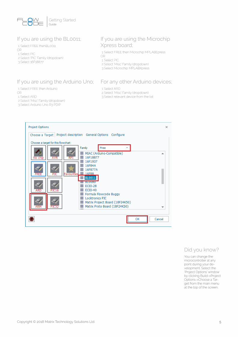
If you are using the BL0011;1. Select FREE thenBL0011
OR1. Select PIC2. Select ‘PIC’ Family (dropdown)3. Select 16F18877
If you are using the Arduino Uno;1. Select FREE then Arduino
OR1. Select ARD2. Select ‘Misc’ Family (dropdown)3. Select Arduino Uno R3 PDIP
If you are using the Microchip Xpress board;1. Select FREE then Microchip MPLABEpress
OR1. Select PIC2. Select ‘Misc’ Family (dropdown)3. Select Microchip MPLABXpress
Did you know?You can change the microcontroller at any point during your de-velopment. Select the ‘Project Options’ window by clicking Build->Project Options->Choose a Tar-get from the main menu at the top of the screen.
For any other Arduino devices;1. Select ARD 2. Select ‘Misc’ Family (dropdown)3. Select relevant device from the list

6Copyright © 2018 Matrix Technology Solutions Ltd.
Getting StartedGuide
Once Flowcode has opened you will be presented with a blank IDE as seen below;
1. ComponentsProvides access to the component library. Double click or drag components onto the simulation panel.
2. Simulation PanelWhere all your components will live. Note; all components you wish to use must be added to the simulation panel.
3. Panel PropertiesHere users select which pin/ port of the microcontroller the components are connected to.
4. Command ToolboxDrag and drop programming icons onto the Flowchart window (5) to construct your program.
4
65
71
2
3
5. Main WindowThis is where you create flowcharts. All programs will have a ‘BEGIN’ and ‘END’, you must fill in the gaps in between with the programming icons from point (4).
6. Project ExplorerThis is where variables and macros (functions) are created, edited and viewed.
7. ToolbarWe use the icons in this toolbar to simulate and program our hardware.

7Copyright © 2018 Matrix Technology Solutions Ltd.
Getting StartedGuide
The simulation panelsIn this next section we will walk you through the 3D interface. The 2D control panel is very similar in operation to the 3D simulation panel, except the Z-axis is locked. Once you have mastered the 3D simulation panel you will quickly understand the 2D control panel.
1. Simulation panel controls There are two methods in which you can interact with the simulation panel; Camera and Cursor mode. It is a dynamic menu, and selecting the ‘Arrow’ icon will change the functionality of the three icons to its right. In camera mode;
a. You can pan (1), rotate (2) and zoom (3) the cam-era. To pan and rotate, hold the left mouse button and drag. To zoom, drag a box to the required size or use the mouse wheel to zoom in/ out.
b. Cursor Mode allows you to move (1), rotate (2) and scale (3) objects. To ‘free move’ the object in the panel, left click and hold the object and drag. Alternatively, if you want to move your object along a constrained axis, left mouse click on the local axes and drag. Rotate and scale work in a similar way.
1 3 4
2
1 2 3

8Copyright © 2018 Matrix Technology Solutions Ltd.
Getting StartedGuide
2. Orientation axesThe 3-axes in the top left corner of the simulation panel allow you to align the camera back to an axis.
3. Tools In this tool box you can adjust the configuration properties of the simulation panel; change background colour, snap to grid, lighting modes and more.
4. Save cameraWith the ‘save camera’ button you can save and load custom camera angles to allow you to swap between your custom positions.

9Copyright © 2018 Matrix Technology Solutions Ltd.
Getting StartedGuide
Section 2: Flowcode ExamplesWe will now run through several examples; LED flasher, creating a latch and finally the use of an LCD screen to create a counter. Each will increase in complexity and at the same time reduce in pro-vided information, requiring you to remember what you’ve learnt in previous examples.

10Copyright © 2018 Matrix Technology Solutions Ltd.
Getting StartedGuide
Template filesFlowcode comes with a selection of template files which are made to assist you with development. These are based on popular development boards from Matrix and 3rd party equipment such as Microchip and Arduino. The template file will have all the necessary hardware components added to the simulation panel, and be configured correctly.
You will be presented with a choice of templates where you can select the most appropriate board for your use . For example, if you’re using the BL0011 and BL0114 combo board, navigate to E-blocks2 section and select BL0011_Combo. We are now ready to begin example 1.
For our first example we will use a template file and in example 2 and 3 we will create a new blank project, to demonstrate both processes. To use template files, start a new project and choose ‘Open Template’.
11Copyright © 2018 Matrix Technology Solutions Ltd.
Getting StartedGuide
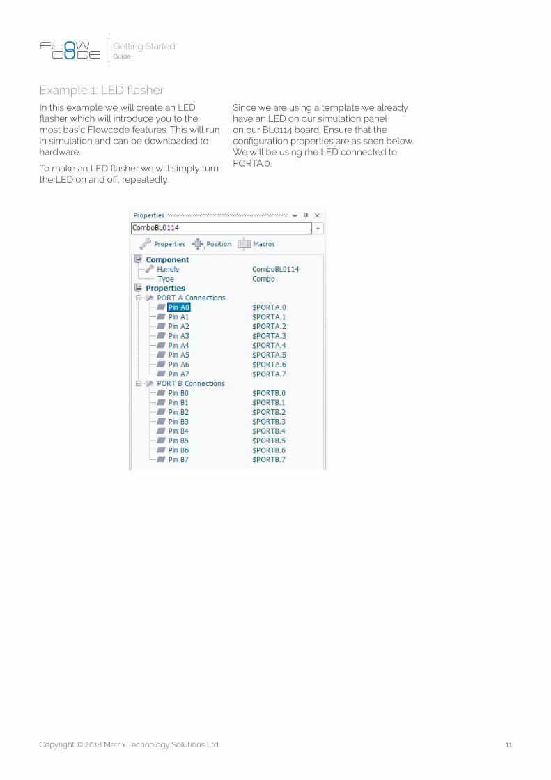
Example 1: LED flasherIn this example we will create an LED flasher which will introduce you to the most basic Flowcode features. This will run in simulation and can be downloaded to hardware.
To make an LED flasher we will simply turn the LED on and off, repeatedly.
Since we are using a template we already have an LED on our simulation panel on our BL0114 board. Ensure that the configuration properties are as seen below. We will be using rhe LED connected to PORTA.0.
12Copyright © 2018 Matrix Technology Solutions Ltd.
Getting StartedGuide
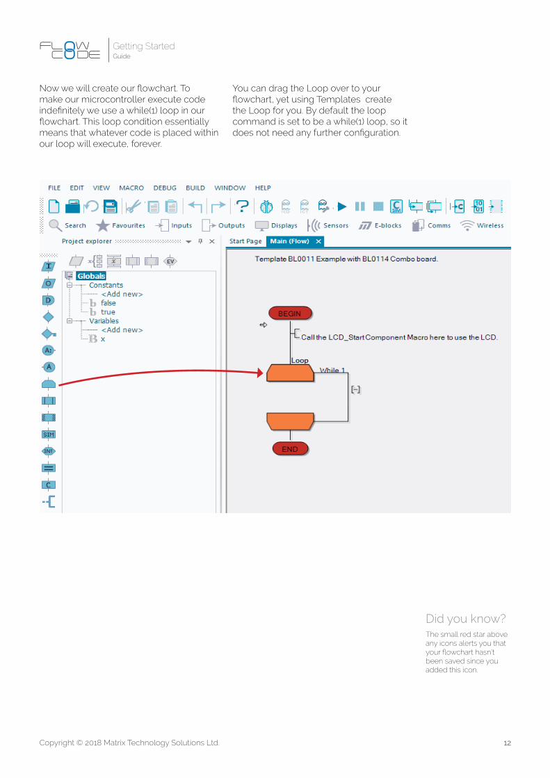
Did you know?The small red star above any icons alerts you that your flowchart hasn’t been saved since you added this icon.
Now we will create our flowchart. To make our microcontroller execute code indefinitely we use a while(1) loop in our flowchart. This loop condition essentially means that whatever code is placed within our loop will execute, forever.
You can drag the Loop over to your flowchart, yet using Templates create the Loop for you. By default the loop command is set to be a while(1) loop, so it does not need any further configuration.
13Copyright © 2018 Matrix Technology Solutions Ltd.
Getting StartedGuide
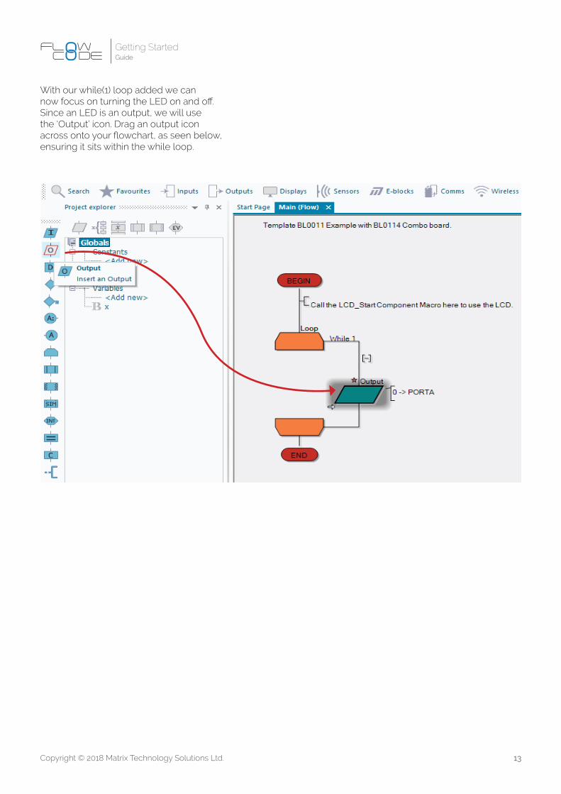
With our while(1) loop added we can now focus on turning the LED on and off. Since an LED is an output, we will use the ‘Output’ icon. Drag an output icon across onto your flowchart, as seen below, ensuring it sits within the while loop.

14Copyright © 2018 Matrix Technology Solutions Ltd.
Getting StartedGuide
You will now need to configure the output icon. This is done by double clicking it to view its properties. Our LED is connected to PORTA.0, so we must configure our properties to match this. Finally, since we want to turn the LED on we write a value of ‘1’ in the ‘variable or value’ box.
To make an LED flash we must turn it on and off. Place another output icon on your flowchart, below the original, and configure it as before. Although this time you should write a value of ‘0’ instead to turn our LED off.
15Copyright © 2018 Matrix Technology Solutions Ltd.
Getting StartedGuide
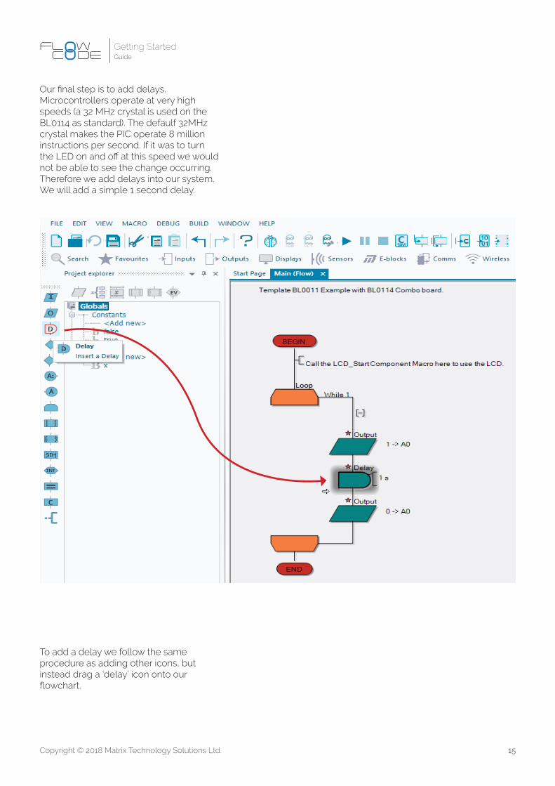
To add a delay we follow the same procedure as adding other icons, but instead drag a ‘delay’ icon onto our flowchart.
Our final step is to add delays. Microcontrollers operate at very high speeds (a 32 MHz crystal is used on the BL0114 as standard). The defaulf 32MHz crystal makes the PIC operate 8 million instructions per second. If it was to turn the LED on and off at this speed we would not be able to see the change occurring. Therefore we add delays into our system. We will add a simple 1 second delay.

16Copyright © 2018 Matrix Technology Solutions Ltd.
Getting StartedGuide
As before, we double click our ‘delay’ icon to configure it for the delay we require. We can see the delay configuration screen below, where we have set a 1 second delay.
Currently we turn our LED on for 1 second, then we turn it off. However, we do not hold the LED off and so it will turn on again very fast. It would therefore appear that the LED is always on. We must add another delay icon after we turn the LED off, which can be seen in the final flowchart below.
17Copyright © 2018 Matrix Technology Solutions Ltd.
Getting StartedGuide
The simple LED flasher is now finished. First we will simulate our program to check it works as required. Then we will write it to hardware, and get a real LED flashing.
To simulate, we use the buttons seen in the image below. The ‘Play’ button begins our simulation. Once in play mode we can pause or stop our simulation. The two icons on the very right allow us to manually
step through our program. As previously mentioned microcontrollers operate at very high speeds…much faster than we can see! We often need to manually step through each icon in order to check that our program is working correctly.
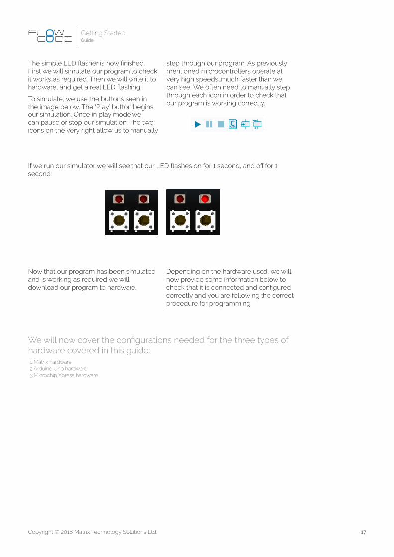
If we run our simulator we will see that our LED flashes on for 1 second, and off for 1 second.
Now that our program has been simulated and is working as required we will download our program to hardware.
We will now cover the configurations needed for the three types of hardware covered in this guide:1. Matrix hardware2. Arduino Uno hardware3. Microchip Xpress hardware
Depending on the hardware used, we will now provide some information below to check that it is connected and configured correctly and you are following the correct procedure for programming.
18Copyright © 2018 Matrix Technology Solutions Ltd.
Getting StartedGuide
1. Matrix hardwareIn this section we will briefly discuss the Matrix hardware.
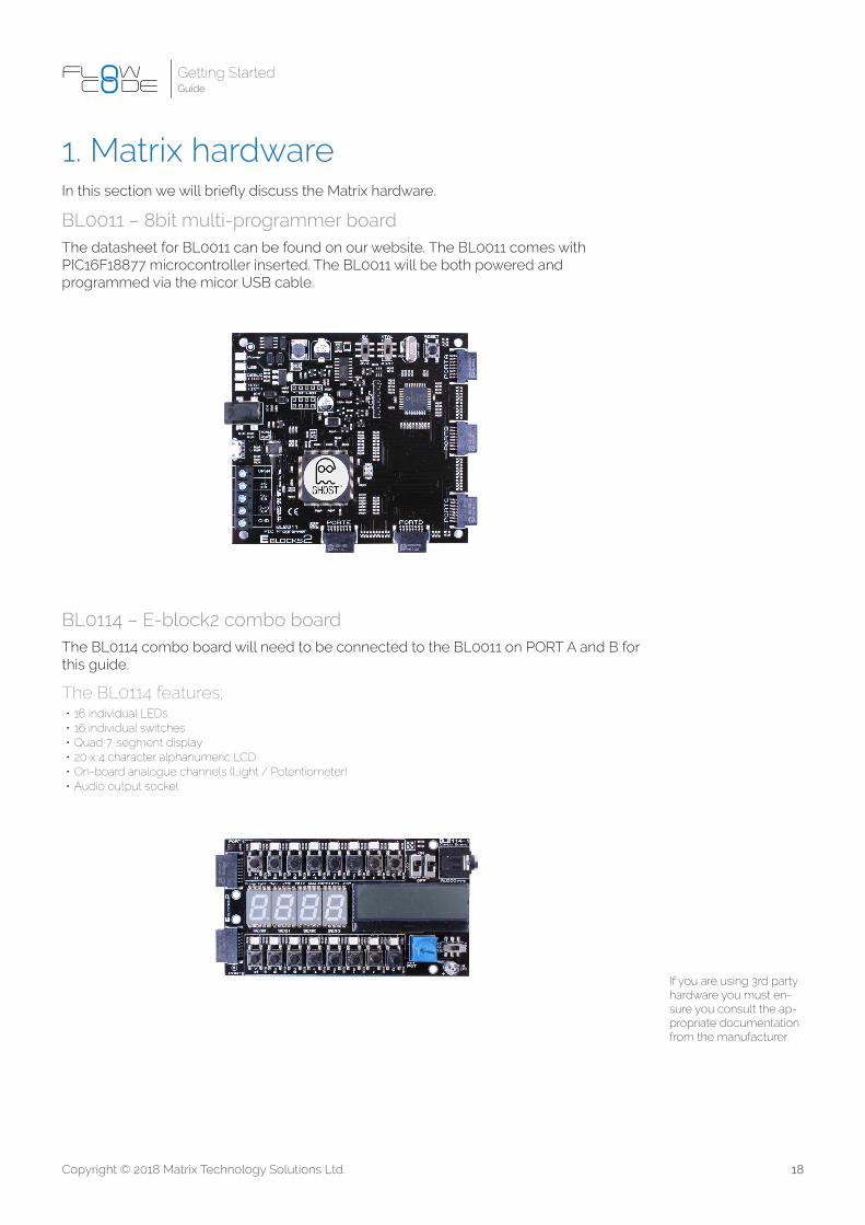
BL0011 – 8bit multi-programmer boardThe datasheet for BL0011 can be found on our website. The BL0011 comes with PIC16F18877 microcontroller inserted. The BL0011 will be both powered and programmed via the micor USB cable.
If you are using 3rd party hardware you must en-sure you consult the ap-propriate documentation from the manufacturer.
BL0114 – E-block2 combo boardThe BL0114 combo board will need to be connected to the BL0011 on PORT A and B for this guide.
The BL0114 features;•16 individual LEDs•16 individual switches•Quad 7-segment display•20 x 4 character alphanumeric LCD•On-board analogue channels (Light / Potentiometer)•Audio output socket

19Copyright © 2018 Matrix Technology Solutions Ltd.
Getting StartedGuide
2. Arduino hardwareIf you are using an Arduino Uno you must ensure you have the Arduino drivers installed before you can program directly from Flowcode. Consult the Arduino website to download the latest drivers for your hardware.
With the drivers installed, and the Arduino microcontroller selected from within Flowcode you should now check that Flowcode has seen your connected
Did you know?If you are using an Arduino, you cannot change properties such as the configuration and clock speed as these are fixed.
hardware. Navigate to Build-> Project Options -> General Options and you will see the image below. From the ‘Programmer Port’ drop down box you must select the appropriate COM port for your Arduino (COM’s is shown in the image below but this might be different on your PC). Note that the COM port will only be shown if your Arduino is connected and the drivers are installed.

20Copyright © 2018 Matrix Technology Solutions Ltd.
Getting StartedGuide
3. Microchip Xpress hardwareIf you are using the Microchip Xpress hardware, ensure you have the correct microcontroller selected from the Project Options menu. As with other hardware, press compile to chip, and Flowcode will program the Xpress board.
Note; There are no drivers to install for the Xpress board, however, check it has been seen correctly by navigating to my computer and the Xpress board should be seen as a mass storage device. After you
Did you know? If you are using the Microchip Xpress board, you won’t be able to complete the third example program in hardware, however, you can still use the simulator.
have programmed your board, you will see the name of your program saved as a .HEX file on your board
Once your flowchart is complete you create a hex file by pressing the button seen below;

21Copyright © 2018 Matrix Technology Solutions Ltd.
Getting StartedGuide
Once we select to program the device a new window will appear on the screen detailing the compilation and programming progress. When complete you should see the program working as desired on hardware. If it is not, ensure that you have followed every step in this tutorial, and that the flowchart is correctly configured.
With your appropriate hardware connected and configured correctly, you must now program the device.
In Flowcode it is easy to download our program to hardware. When downloading code to our device we again have a shortcut toolbar. There are 3 icons in the programming section of the toolbar, as seen below. The left icon compiles our flowchart into a .C file, while the middle
icon compiles the Flowchart into a .Hex file. These two options are useful if you are using Flowcode to create your program, but 3rd party hardware to flash your microcontroller. With these examples we are using Flowcode to flash our microcontroller, and as such we use the right hand icon. This compiles and programs our microcontroller in one button press.

22Copyright © 2018 Matrix Technology Solutions Ltd.
Getting StartedGuide
Example 2: Creating a latchIn the next two examples we will assume you are now getting to grips with Flowcode and will provide you with a few less details. We’ll still walk you through any new features though, so do not worry.
In this example we will look at adding a switch to the simulation panel, and creating a latching system from a simple momentary push-to-make switch. First you must create a new program and select the appropriate microcontroller as discussed earlier in this guide.
We will create a program that reads the switch and lights up an LED when pressed. When the user releases the switch the LED should stay on until the switch is pressed again. This will introduce us to two new programming concepts; inputs and variables.
Consult the table below for connection properties relevant to the hardware you are using;
BL0011 Arduino Uno Xpress
LED A0 A0 A0
Switch B0 D0 A5
We will now create a variable. When reading inputs we must have a variable to save the state of the switch press. To create a variable click on the down arrow next to ‘Variables’ in the Project Explorer and click ‘Add new’.
First we will add our components to the simulation panel. We need;
•LED (5mm, PCB)•Switch (Push, Panel)
If you double click on a component in the System Panel you can access its Properties where you can change port connections of the component if required.

23Copyright © 2018 Matrix Technology Solutions Ltd.
Getting StartedGuide
The ‘Edit variable name’ window will appear. There are 4 sections we should fill out. Although the description is optional, it is good practice to do so.
a. Here we’ve called our variable SwitchPressed. Note you cannot have spaces in variable names.
b. We have initialised our variable to zero to ensure no old values remain in memory
c. We added a brief description so that later we can remember exactly what this variable does. This is
purely a visual hint, and has no bearing on function-ality.
d. We are selecting this as a type ‘byte’, therefore it can save any value between 0-255.

24Copyright © 2018 Matrix Technology Solutions Ltd.
Getting StartedGuide
Next, add a while(1) loop to the flowchart, as we did in the first LED flasher example. Then, add an input to the flowchart within this loop. Configure the input as below, ensuring that you select Single Bit; PORTA.0 (for the Arduino Uno or Xpress board you will need to select the same pin that the switch is connected to, see the
table above). You must also select to save to the variable called SwitchPressed. This reads the switch whenever we call this icon, and will save its state to the variable SwitchPressed. If the switch is pressed, it will return a ‘1’, if nothing is pressed, it will return a ‘0’.
Did you know?Whenever we use switches with microcontrollers we need to consider a thing called ‘bounce’. Bounce occurs when a user presses a switch and the generated mechanical movement can cause the switch to physically bounce between the on/ off state multiple times, even though we only intended to press it once. Since microcontrollers operate so fast, this will result in unwanted switch presses. Imagine a small microcontroller system where a person working on a ticket gate is pressing a switch to count people attending a sporting event. If de-bounce wasn’t implemented, they may press a switch as a person walks past and the mechanical bounce of the switch may count 3 people, despite only feeling like it was pressed once.We overcome this by adding de-bounce. De-bounce can be added in hardware, or more commonly through programming. The simplest way to overcome bounce in software is to add a small delay after a switch is pressed. A value of 20-50ms is typically enough.Add a delay of 50ms directly after your input icon to allow for bounce.

25Copyright © 2018 Matrix Technology Solutions Ltd.
Getting StartedGuide
With the value now stored in the variable ‘SwitchPressed’ we must do something with it. We could just add a single output icon to turn on the LED whenever we press the switch, but that’s a bit too simple. Instead we will make a latch, so when the switch is pressed it turns on the LED and holds it on until the switch is pressed again.
There are several ways to achieve this, but for this one we need a second variable,
which we have named ‘Flag’. What we want to do is toggle the value of Flag only when the button is pressed. To achieve this we use a ‘Decision’ command. The first thing we need to do is determine whether the switch was pressed or not. Drag a decision command onto the flowchart (underneath the delay icon), and configure it as seen below;
Since we are creating a latch we only want to modify the value of Flag when the switch has been pressed. Therefore, we will only place code in the ‘Yes’ branch of the decision. We leave the ‘No’ branch empty. Once the switch has been pressed we want to toggle the value of Flag from 0-1 or vice versa.
Place a calculation box within the Yes branch. The statement here Flag = !Flag will toggle the value of Flag between 1 and 0 each time it is executed.
Our final command is to output the status of Flag to the LED. We do this with an output command, as we did in the first example. However, rather than writing a 1 or 0 in the ‘Variable or Value’ box we write the variable name Flag.

26Copyright © 2018 Matrix Technology Solutions Ltd.
Getting StartedGuide
The final flowchart can be seen below:
You should now both simulate and download your code to hardware for verification. As you press the switch on your board, the appropriate LED should illuminate, and stay that way until you press the switch again. Once confirmed working, move onto the final exercise.

27Copyright © 2018 Matrix Technology Solutions Ltd.
Getting StartedGuide
Example 3: LCD screen and counterIn the final example we will step through creating a simple counter, and displaying that value on an LCD display. (If you are using the Xpress board, this exercise can only be performed in simulation mode).
In this exercise you will be introduced to a new flowchart command; the component macro. A component macro is how we interface with the more complex components in Flowcode. For simple things like switches and LEDs we can use inputs and outputs. However, if we want to talk to an LCD screen we may need to execute a series of commands back and forth. Component macros are libraries of code that we have developed that simplify such things. A component macro therefore is a sub-routine, and is a block of code that can be called by a single flowchart icon.
Connection BL0011 Arduino
Data0 PORTB.0 PORTD.0
Data1 PORTB.1 PORTD.1
Data2 PORTB.2 PORTD.2
Data3 PORTB.3 PORTD.3
Register Select PORTB.4 PORTD.4
Enable PORTB.5 PORTD.5
We will now quickly progress through a few steps where we are doing familiar coding. If you struggle to keep up you can check the code listing at the end of this section.
a. Counter = Counter + 1
1. Create a variable called ‘Counter’ of type byte, and initialise it to zero.
2. Placeawhile(1)loopintoyourflowchart3. Place a calculation box within this while(1)
loop, and increment the variable counter us-ing a calculation command
4. Place a 1 second delay after the calculation box.
As with example 2, we will step through familiar concepts with less detail, but any new features will be carefully explained.
Create a new flowchart with the correct microcontroller selected and add an LCD (Generic, 20 x 4) screen to the simulation panel. This is the screen used on both the standalone BL0169 E-blocks2, and the BL0144 combo board used in this tutorial.
With the LCD screen added to the simulation panel you should check its connection properties. Consult the table below to check connection properties;

28Copyright © 2018 Matrix Technology Solutions Ltd.
Getting StartedGuide
If we were to run this program now it would simply count up from 0-255. Since we are using a variable type of Byte for ‘Counter’ it will reach 255 and roll back around to zero where it will continue counting again.
Despite having a counter we do not yet have a method of displaying this information on the LCD screen. We will now introduce component macros. Add a component macro to the very start of your flowchart, above the while(1) loop, as seen below;
Open its configuration properties, as usual, by double clicking on the component macro. You will see the box below. Press the + button next to the LCD_4x20 component to access the available component macros.
29Copyright © 2018 Matrix Technology Solutions Ltd.
Getting StartedGuide
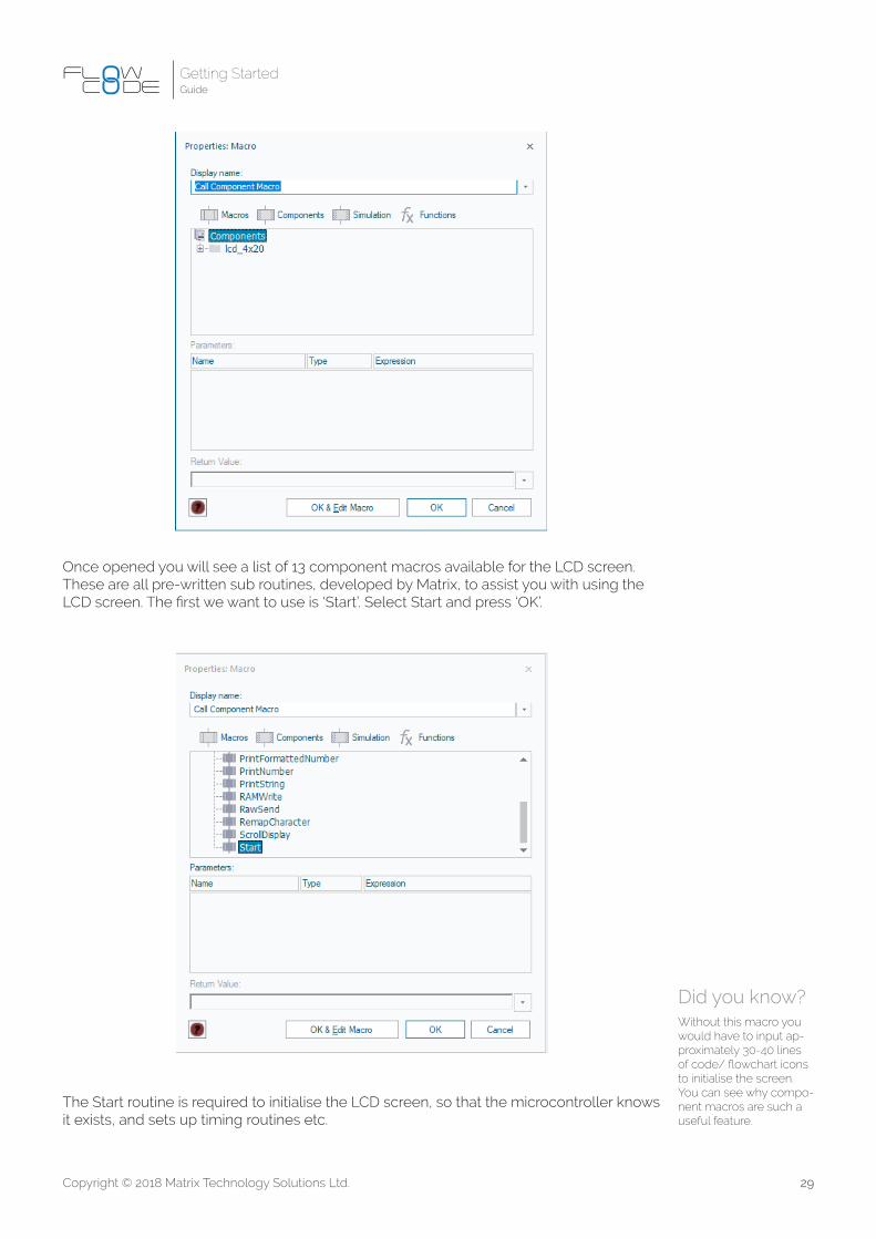
Once opened you will see a list of 13 component macros available for the LCD screen. These are all pre-written sub routines, developed by Matrix, to assist you with using the LCD screen. The first we want to use is ‘Start’. Select Start and press ‘OK’.
The Start routine is required to initialise the LCD screen, so that the microcontroller knows it exists, and sets up timing routines etc.
Did you know? Without this macro you would have to input ap-proximately 30-40 lines of code/ flowchart icons to initialise the screen. You can see why compo-nent macros are such a useful feature.

30Copyright © 2018 Matrix Technology Solutions Ltd.
Getting StartedGuide
With the screen initialised we need two more component macros. The first is to display the value of the variable ‘counter’ on the LCD screen. Add another component macro within the while(1) loop, directly above the calculation box. Configure it to be a ‘PrintNumber’ macro, however, you will notice that there is a parameter box that you must now fill in, called ‘Number’. Here we must write the name of our variable; Counter. Each time this command is now executed it will display whatever value we currently have saved in counter.
There is one final component macro we need. We want our value of Counter to always be displayed in the top left corner (X,Y position; 0,0). Currently our program will write the value of Counter on the LCD screen, however, the cursor will move each time we write a value and we will end up with something like below;
What we need to do is clear the LCD screen each time we write a new value. Luckily for us executing a clear screen routine also moves the cursor position back to (0,0). Add another component macro above the PrintNumber macro, and configure it to ‘Clear’.
We have now finished our third and final example. You should first test your program is right by comparing it to the code listing below. Simulate, before downloading to hardware to confirm it works.
Did you know? The BL0114 combo board has small slide switches used to turn the LCD screen and the 7SEG LCD screen on and off. Make sure that this switch in in the ‘on’ position for the LCD screen when using.

31Copyright © 2018 Matrix Technology Solutions Ltd.
Getting StartedGuide
We have now introduced you to the most basic principles within Flowcode. These principles are the foundation of all microcontroller development. There are more complex features that we have not covered, but at this point you should have an understanding of how Flowcode works, and be able to begin experimenting for yourself as to other features.

32Copyright © 2018 Matrix Technology Solutions Ltd.
Getting StartedGuide
Version Author Date Changes
1.0 PN 24/06/2016 Document creation
1.1 PN 12/07/2016 Image updates, minor changes
1.2 RT 04/05/2018 Update re. Flowcode 8 and E-blocks2

Matrix Technology Solutions LimitedThe Factory
33 Gibbet StreetHalifax HX1 5BAUnited Kingdom
t: +44 (0) 1422 252380f: +44 (0) 1422 341830
@MatrixTSL
www.matrixtsl.com