getting physical with usb type-c - alex...
TRANSCRIPT

Getting Physical With USB Type-CWINDOWS 10 RAM FORENSICS AND UEFI ATTACKS
ALEX IONESCU [@AIONESCU]RECON BRUSSELS 2017

Speaker Bio• Vice President of EDR Strategy at CrowdStrike, a security startup
• Reverse engineering NT since 2000 • Lead kernel developer of ReactOS
• Co-author of Windows Internals
• Instructor of worldwide Windows internals classes
• Conference speaking:
• SyScan 2012-2015, Infiltrate 2015
• NoSuchCon 2014, 2013, Breakpoint 2012
• Recon 2010-2017, 2006
• Blackhat 2016, 2015, 2013, 2008
• For more info, see www.alex-ionescu.com / @aionescu

Introduction
• The appearance of cheap, of non-FPGA based, USB<->PCIe devices makes commodity access to the PCIe bus a reality
• And with it comes Bus Mastering / DMA to machines without an IOMMU
• The appearance of USB Type-C brings Thunderbolt 3 access to a much wider range of machines than ever before
• Even mid-range Dell laptops (600-1000$) now have USB Type-C support
• The appearance of generic USB Type-C to PCIe bridges allows connecting a USB3380-like device to any USB Type-C port for a few hundred dollars…

ITS OVER NINE THOUSAND!!!! (DOLLARS)

Or… 350$...

Outline
• Previous Research
• USB Type-C Basics
• The USB3380 Bridge Controller
• User Mode Driver Framework (UMDF) Crash Course
• Windows Physical Memory Forensics
• Attacking Windows/UEFI
• Conclusion

Previous ResearchSHOULDERS OF GIANTS

External Port DMA Attacks
• First publically shown with FireWire
• Can also be extended thrugh ExpressCard to PCI Bridges
• Essentially possible because those external ports give access to PCI Bus
• Led many OS vendors to restrict DMA/Bus Mastering to particular classes of devices
• And/or block device installation until after log-on
• And/or not allow DMA while the machine is locked

Thunderbolt Attacks
• Popularized by Snare first, then Trammell Hudson
• Relied at first on Option ROM Firmware of Ethernet Controller• No SecureBoot on Apple EFI (based off of 1.12)
• Later moved on to custom FPGA package with a PCIe to TB bridge
• Led Apple to enable and leverage IOMMU (VT-d) by default to protect access to OS memory areas
• Trammell Hudson then extended the attack to TB2
• Not seen as an issue on PCs, as TB/TB2 was practically non-existent
Thunderbolt Revisited
• Recent re-emergence thanks to work done by Joe Fitzpatrick
• Discovered USB3380 device which provides a USB 3.0<->mini-PCIe interface
• SLOTSCREAMER – used on external card with mini-PCIe to PCIe
• Combined with PCIe<->TB adapter (ALLOYVIPER) to create external attack interface
• Mostly focused on Linux/Mac – slow (< 3MB/s)
• Limited to 32-bit DMA only due to USB3380 hardware
• No Option ROM support on the hardware

Thunderbolt on Windows
• Ulf Frisk recently took the SLOTSCREAMER work and read through the USB3380 datasheet, implementing DMA channels on the USB side (PCILeech)
• Now allows for 150MB/s transfer speeds
• Bypassed need to use HW OEM tools (which has been bought by Broadcom now and under NDA) with a Linux Driver
• Leveraged WinUSB/Android driver to allow for simple access from the Windows side with a command-line tool• But still required Linux-based PCI driver to flash custom firmware
• Created implants for Linux, Mac, and Windows

My Contributions
• Fixed configuration register bugs in PCILeech Firmware
• Some reserved bits were incorrectly set, and some useful bits not
• Increased stability/usability of PCILeech using USB 2.0
• Either some cables or some hardware often “dies out” after a while
• Designed Windows-based UMDF 2.0 Driver for Firmware Flash
• Removed need for initial Linux-based flash
• Created universal implant technique that always works < 4GB
• Leveraging UEFI Runtime Services and HAL Heap
• Extended previous work to USB Type-C
• Much more prevalent than Thunderbolt on PC (and now Mac)

USB Type-C BasicsTHUNDERBOLT 3 FOR THE MASSES

What is USB Type-C
• Specification for connectors and cables (also called USB-C)
• Reversible connector, 100W power delivery (PD standard)
• Supports “Alternate Modes” such that signaling can be used for DisplayPort, Thunderbolt, HDMI, etc…
• Thunderbolt 3 specification allows routing signals over USB-C
• Defined in June 2015
• With TB3 support part of SkyLake Chipset, most Windows laptop manufacturers are now including USB-C ports (and motherboards)
• Apple has moved to fully embrace only USB-C
ThunderBolt 3 Support in Windows
• Intel closely guards information about TB3 – closed specification and closed chipsets
• Not even Windows has a native TB3 driver• Laptops must ship with Intel’s own TB3 stack
• BIOS should also have TB3-specific options that activates “security levels”
• Intel “Secure Connect” Driver responds to new TB3 devices, and only an Administrator can authorize the insertion of a new device
• Reverse engineering required to understand where the security boundary truly lies

ThunderBolt 3 Support in BIOS Options (Dell)
OFF by default
ON by default

Issues with ThunderBolt 3 “Security”
• If enabled Pre-Boot, there’s no actual “Security” – all devices are whitelisted, even after Windows boots up
• Requires physically removing cable and re-inserting (probably too late )
• “Legacy Mode” obviously bypasses all security as well, and willlikely be needed for a while as people migrate older TB/TB2 devices
• Even in the strictest security mode/level, the only thing the Intel Secure Connect Driver sees is the Akitio Thunder3 Bridge• Authorizing it while empty or with a different PCI card results in
authorizing it for any other possible future PCI card in the future
• Really, Intel?! “Strong Unique ID”!?
• “Always allow Dell Docks” is just a VID/DID check…

USB-3380THE CHIP, THE KIT, THE LEGEND

What is the USB-3380?
• ~15$ PCIe Gen2 to USB 3.0 Bridge Peripheral Controller
• One USB 3.0 connector at one end, with multiple endpoints• 4x DMA Channels (IN/OUT Pairs)
• 2x PCI I/O Channel (IN/OUT Pair)
• 2x Configuration & Status Register (CSR) Channel (IN/OUT Pair)
• Almost fully configurable PCI Header (VID/DID/BARs) and USB Controller settings
• Embedded 8051 MCU lives in EEPROM and also has full access
• Available in various development kits from Bplus in Taiwan

USB-3380 Limitations
• No support for Option ROM, sadly
• DMA transactions are be limited to addresses below < 4GB
• Due to 32-bit width of DMAADDR register
• DMA transaction on MMIO/Reserved/Memory Hole requires hard reset
• Only one vendor makes dev kit/board (Bplus)
• PP3380-AB is PCIe card with 8KB EEPROM
• USB3380-EVB is mini-PCIe card, but small 256 byte EEPROM
• EC3380-AB is ExpressCard, does not appear to work correctly
• PLX (who makes the chip) now owned by Broadcom – NDAs in place

Out of the box setup to enable USB
• In its default state, the USB3380 will not enable the USB endpoint, and will have a default PLX device ID and vendor ID (no Bus Master)
• It must be programmed through the PCIe interface with new Serial EEPROM data (which some refer to as its “firmware”)
• Start with {0x5A, 0x00} Header (Magic, Configuration Register Load)
• Follow with size in Big Endian (i.e.: {0x2A, 0x00}, 42 bytes)
• Set USBCTL to 0x3849 {0x23, 0x10, 0x49, 0x38, 0x00, 0x00}
• USBCTL is register 8Ch, so the 0x23’rd 4-byte register index in USB Controller
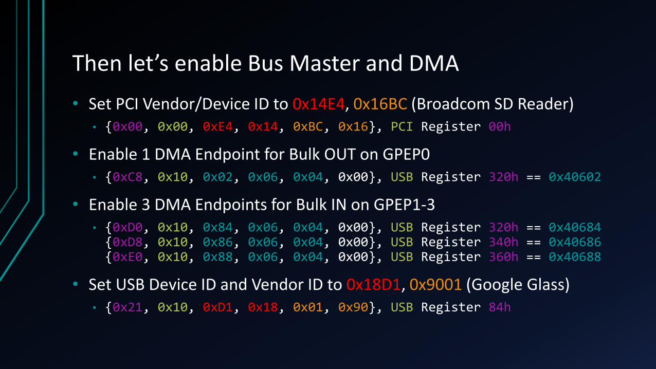
Then let’s enable Bus Master and DMA
• Set PCI Vendor/Device ID to 0x14E4, 0x16BC (Broadcom SD Reader)• {0x00, 0x00, 0xE4, 0x14, 0xBC, 0x16}, PCI Register 00h
• Enable 1 DMA Endpoint for Bulk OUT on GPEP0• {0xC8, 0x10, 0x02, 0x06, 0x04, 0x00}, USB Register 320h == 0x40602
• Enable 3 DMA Endpoints for Bulk IN on GPEP1-3• {0xD0, 0x10, 0x84, 0x06, 0x04, 0x00}, USB Register 320h == 0x40684{0xD8, 0x10, 0x86, 0x06, 0x04, 0x00}, USB Register 340h == 0x40686{0xE0, 0x10, 0x88, 0x06, 0x04, 0x00}, USB Register 360h == 0x40688
• Set USB Device ID and Vendor ID to 0x18D1, 0x9001 (Google Glass)• {0x21, 0x10, 0xD1, 0x18, 0x01, 0x90}, USB Register 84h

A quick note on the PP3380-AB
• This development board has a full 8KB of EEPROM which can be used to store actual 8051 program memory and code
• The 8051 has full access to both the USB and PCI side
• Therefore, even though in this presentation we will be driving the USB side from a separate physical computer connected over USB…
• …the entire attack could be replicated in a much smaller package
• It is also possible to solder an EEPROM to the appropriate pins on the USB-3380 in the –EVB mini-PCIe package
Diagnostic LEDs
• A nice feature of the USB3380-EVB are the fact that 3 Orange LEDs and 1 Blue LED are connected to GPIO0-3 on the controller
• USB Controller Register GPIOCTRL (50h) can be used to set Outputs to ENABLE and then drive output on Pin 0-3.
• GPIO0-2 are the row of Orange LEDs, GPIO3 is the Blue LED
• Can be used during development to indicate success/failure while reading/writing DMA or flashing the EEPROM…
• But also extremely useful when running in 8051 mode where the attack is being driven off the MCU directly

Plug it in…
• One end sees a USB Serial Port Controller
• Missing a driver
• The other end sees nothing yet (USB is not yet activated)
• Now we need to write a driver for it!• And then load something for the USB side as well, once activated
• “Writing PCI-Express Drivers Is Hard – Let’s go shopping!”• UMDF Barbie

D(o)r(on). Holan, or How I Learned to Stop Writing Kernel Code and Love UMDFUMDF DRIVER WRITING CRASH COURSE

Motivation
• We need to flash the firmware on first use, but this requires access to PCIe MMIO and taking over the device with a kernel driver
• Kernel drivers are complex, and require driver signatures – which are extremely stringent on Windows 10 Anniversary Update
• Thanks to modern advances in Windows’ user-mode driver framework (UMDF), it’s actually possible to completely write a PCI-Express driver in 100% user-mode code
• And no “real” signature requirement – only a “trusted CA” check on install
• All device MMIO mappings & register access can be done in Ring 3
Step 1, Create the INF
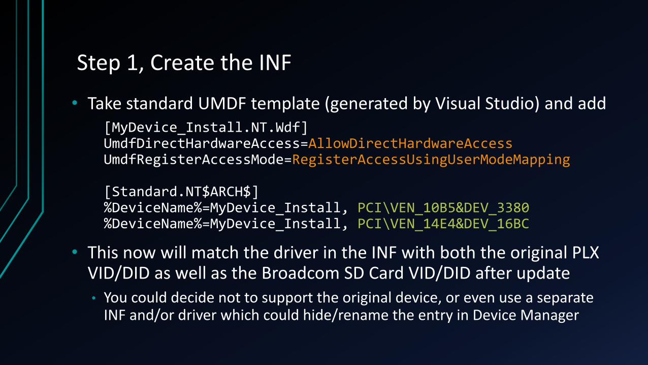
• Take standard UMDF template (generated by Visual Studio) and add[MyDevice_Install.NT.Wdf]UmdfDirectHardwareAccess=AllowDirectHardwareAccessUmdfRegisterAccessMode=RegisterAccessUsingUserModeMapping
[Standard.NT$ARCH$]%DeviceName%=MyDevice_Install, PCI\VEN_10B5&DEV_3380%DeviceName%=MyDevice_Install, PCI\VEN_14E4&DEV_16BC
• This now will match the driver in the INF with both the original PLX VID/DID as well as the Broadcom SD Card VID/DID after update
• You could decide not to support the original device, or even use a separate INF and/or driver which could hide/rename the entry in Device Manager

Step 2: Create the Driver Object
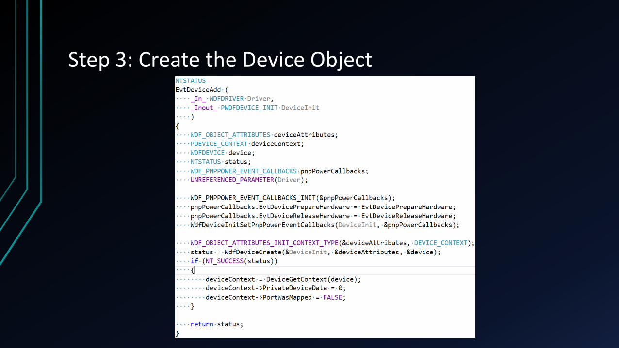
Step 3: Create the Device Object

Step 4: Map MMIO & Flash When Added

Step 5: Clean Up On Remove

What’s Next?
• Now that we’ve flashed the PCI device, an Android WinUSBinterface will come up if the Google ADB Drivers are installed
• This is the current way that pcileech is set up, and while not the most efficient, allowed me to re-use much of the code
• Long-term plan is to write custom UMDF driver for the USB side as well, to avoid faking the VID/DID and requiring a Google Driver to be installed
• Also prefer UMDF over WinUSB programming
• Pcileech has a plethora of options and implants/attacks, but we won’t be using any of the built-in capabilities – we’ll be looking at some highly custom and Windows-specific DMA “fun”

THE MYSTICAL HAL HEAPTHE FINAL WORD ON ABUSING THE HAL

Historical Overview
• HAL requires access to virtual address space before the memory manager in the kernel has been setup
• Historically, this was done by using a hard-coded value to define the “HAL Reserved VA” in the kernel and in HAL:
• 0xFFC00000->0xFFFFFFFF (sign-extended on x64) for a total of 4MB
• HAL Virtual Address Space is used to store “HAL Heap”
• 1 MB after start of HAL Reserved VA (0xFFD00000)
• In Windows 10 Creator’s Update, this space is now randomized• Boot loader picks a region and passes it through the Loader Block
HAL Heap Misunderstandings
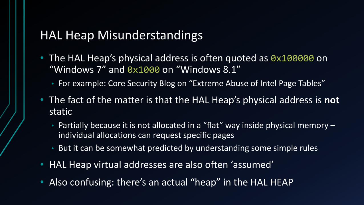
• The HAL Heap’s physical address is often quoted as 0x100000 on “Windows 7” and 0x1000 on “Windows 8.1”
• For example: Core Security Blog on “Extreme Abuse of Intel Page Tables”
• The fact of the matter is that the HAL Heap’s physical address is not static
• Partially because it is not allocated in a “flat” way inside physical memory –individual allocations can request specific pages
• But it can be somewhat predicted by understanding some simple rules
• HAL Heap virtual addresses are also often ‘assumed’
• Also confusing: there’s an actual “heap” in the HAL HEAP
HAL Physical / Virtual Allocator
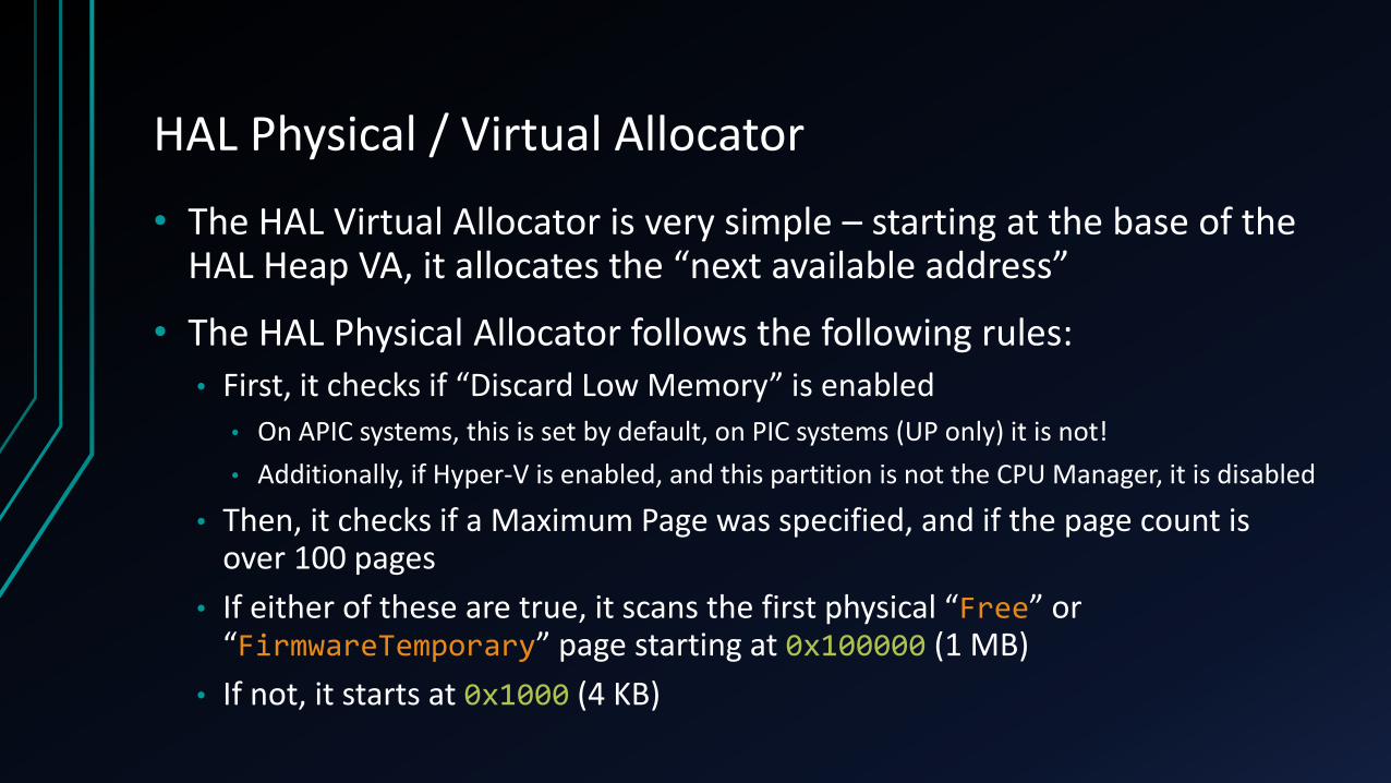
• The HAL Virtual Allocator is very simple – starting at the base of the HAL Heap VA, it allocates the “next available address”
• The HAL Physical Allocator follows the following rules:• First, it checks if “Discard Low Memory” is enabled
• On APIC systems, this is set by default, on PIC systems (UP only) it is not!
• Additionally, if Hyper-V is enabled, and this partition is not the CPU Manager, it is disabled
• Then, it checks if a Maximum Page was specified, and if the page count is over 100 pages
• If either of these are true, it scans the first physical “Free” or “FirmwareTemporary” page starting at 0x100000 (1 MB)
• If not, it starts at 0x1000 (4 KB)

HAL Physical Addresses
• Here’s a sample at very early boot – note that the HAL has already allocated 5 pages (which it marks as HALCachedMemory)
kd> !loadermemorylist fffff803`6916c910
Base Length Type0000000000 0000000001 (32) FirmwareReserved ( 4 Kb )0000000001 000000009f ( 5) FirmwareTemporary ( 636 Kb )0000000100 0000000001 (20) MemoryData ( 4 Kb )0000000101 0000000001 ( 7) OsloaderHeap ( 4 Kb )0000000102 0000000001 ( 4) LoadedProgram ( 4 Kb )0000000103 0000000005 (26) HALCachedMemory ( 20 Kb )0000000108 00000000a3 ( 5) FirmwareTemporary ( 652 Kb )00000001ab 000000002a (20) MemoryData ( 168 Kb )
• The pages began their allocation at 0x103 due to existing page tables that were allocated, a boot loader heap allocation, and some program code
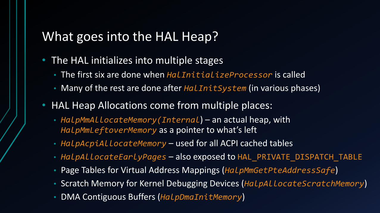
What goes into the HAL Heap?
• The HAL initializes into multiple stages
• The first six are done when HalInitializeProcessor is called
• Many of the rest are done after HalInitSystem (in various phases)
• HAL Heap Allocations come from multiple places:
• HalpMmAllocateMemory(Internal) – an actual heap, with HalpMmLeftoverMemory as a pointer to what’s left
• HalpAcpiAllocateMemory – used for all ACPI cached tables
• HalpAllocateEarlyPages – also exposed to HAL_PRIVATE_DISPATCH_TABLE
• Page Tables for Virtual Address Mappings (HalpMmGetPteAddressSafe)
• Scratch Memory for Kernel Debugging Devices (HalpAllocateScratchMemory)
• DMA Contiguous Buffers (HalpDmaInitMemory)
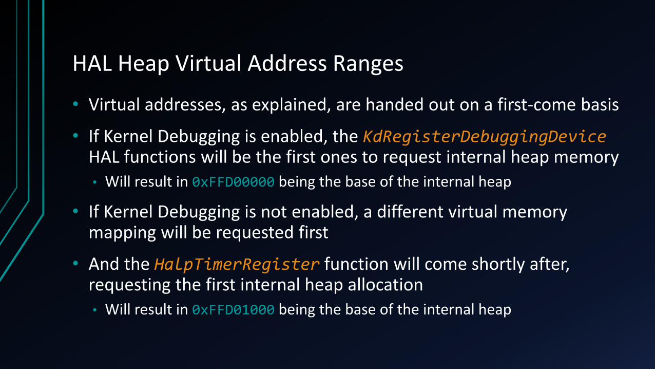
HAL Heap Virtual Address Ranges
• Virtual addresses, as explained, are handed out on a first-come basis
• If Kernel Debugging is enabled, the KdRegisterDebuggingDeviceHAL functions will be the first ones to request internal heap memory• Will result in 0xFFD00000 being the base of the internal heap
• If Kernel Debugging is not enabled, a different virtual memory mapping will be requested first
• And the HalpTimerRegister function will come shortly after, requesting the first internal heap allocation
• Will result in 0xFFD01000 being the base of the internal heap

What to expect in HAL Heap before HalInitSystem
• If debugging is enabled, a KD Debug Device will be registered
• Will be first allocation at 0xFFD00000
• Could contain OEM-specific and name-specific data at the end
• The HAL initializes the TSC timer in HalpTimerInitSystem
• Registers a HAL Timer Object (HalpRegisteredTimers)
• The HAL turns off Legacy USB Interrupts during Errata Initialization
• Registers a HAL USB Controller Object (HalpUsbControllerList)
• If debugging is enabled, a KD Debug Device will be marked in use
• Registers a HAL Device Object (DeviceList) – copy of KD Debug Device

I SEE HEX EVERYWHERE

What did we just see?
• One DEBUG_DEVICE_DESCRIPTOR (0xF8 bytes)
• One REGISTERED_TIMER object (similar to REGISTERED_INTERRUPT_CONTROLLER in symbols) (0x150 bytes)• With 0x4 bytes of “custom data” following it (aligned to 0x8 bytes)
• Followed by its Resource Format String (0x94 Length, 0x96 Maximum Length)
• Incorrectly allocated as 0x94 * sizeof(WCHAR) (0x128 bytes)
• Now at 0x378 – a REGISTERED_USB_CONTROLLER (0x20 bytes)
• And then a DEVICE_IN_USE (0x18 bytes)
• Followed by the device – the same DEBUG_DEVICE_DESCRIPTOR (0xF8 bytes)
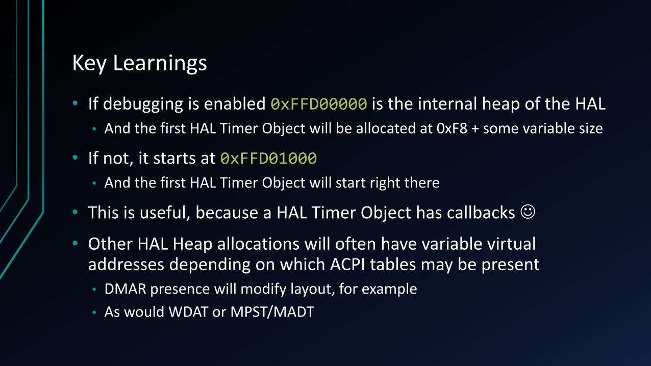
Key Learnings
• If debugging is enabled 0xFFD00000 is the internal heap of the HAL
• And the first HAL Timer Object will be allocated at 0xF8 + some variable size
• If not, it starts at 0xFFD01000
• And the first HAL Timer Object will start right there
• This is useful, because a HAL Timer Object has callbacks
• Other HAL Heap allocations will often have variable virtual addresses depending on which ACPI tables may be present• DMAR presence will modify layout, for example
• As would WDAT or MPST/MADT
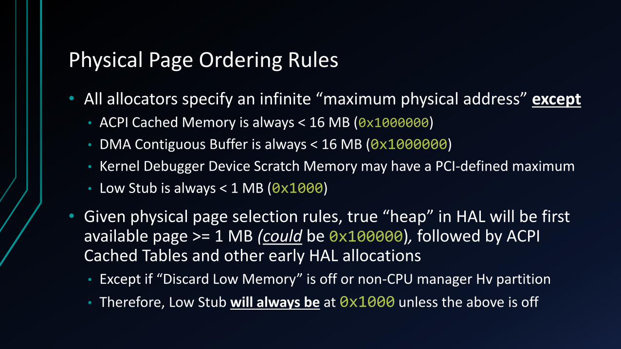
Physical Page Ordering Rules
• All allocators specify an infinite “maximum physical address” except
• ACPI Cached Memory is always < 16 MB (0x1000000)
• DMA Contiguous Buffer is always < 16 MB (0x1000000)
• Kernel Debugger Device Scratch Memory may have a PCI-defined maximum
• Low Stub is always < 1 MB (0x1000)
• Given physical page selection rules, true “heap” in HAL will be first available page >= 1 MB (could be 0x100000), followed by ACPI Cached Tables and other early HAL allocations
• Except if “Discard Low Memory” is off or non-CPU manager Hv partition
• Therefore, Low Stub will always be at 0x1000 unless the above is off
The Low Stub Mystery
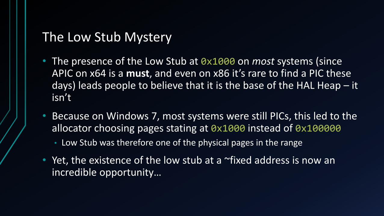
• The presence of the Low Stub at 0x1000 on most systems (since APIC on x64 is a must, and even on x86 it’s rare to find a PIC these days) leads people to believe that it is the base of the HAL Heap – it isn’t
• Because on Windows 7, most systems were still PICs, this led to the allocator choosing pages stating at 0x1000 instead of 0x100000• Low Stub was therefore one of the physical pages in the range
• Yet, the existence of the low stub at a ~fixed address is now an incredible opportunity…

What is the Low Stub?
• The Low Stub is actually the PROCESSOR_START_BLOCK structure:
• It is used when resuming from ACPI Sleep Vector, as well as when initializing the Application Processors (APs)

Why it matters
0: kd> dt /p nt!_KPROCESSOR_STATE 1090 SpecialRegisters.Cr3
+0x000 SpecialRegisters :
+0x010 Cr3 : 0x1ab000 <= KERNEL PAGE DIRECTORY
0: kd> dt /p nt!_KPROCESSOR_STATE 1090 ContextFrame.Rip
+0x0e0 ContextFrame :
+0x0f8 Rip : 0xfffff800`83249010 <= KERNEL ENTRY POINT
0: kd> dt /p nt!_KPROCESSOR_STATE 1090 ContextFrame.Rsp
+0x0e0 ContextFrame :
+0x098 Rsp : 0xffffba81`c6f78ff8 <= KERNEL STACK
0: kd> dt /p nt!_KPROCESSOR_STATE 1090 ContextFrame.Rcx
+0x0e0 ContextFrame :
+0x080 Rcx : 0xfffff800`81c01930 <= LOADER BLOCK
0: kd> ? $ppoi(1078)
Evaluate expression: -3108864 = ffffffff`ffd09000 <= LOW STUB VIRTUAL ADDRESS

Low Stub Forensic Fun
• Now that we’re armed with the low stub’s location (on most systems), we have the location of the HAL Heap in VA (even when randomized in Creator’s Update)
• Even on systems with Discard Low Memory disabled, one can scan at 0x1000and attempt to locate the structure heuristically
• We also have the kernel’s page directory / CR3 structure, which is critical for finding virtual addresses in physical memory and building a memory map
• Finally, on systems that use ACPI Sleep (most of them…) this presents an interesting persistence technique (out of scope)

The ACPI BIOS Multi Node
• We said earlier that a “different allocation” will end up at 0xFFD00000 in the case where debugging is disabled
• This is actually done either by HalInitSystem when initializing ACPI, or, much more likely, done as soon as something earlier queries the ACPI Table (either in HalInitializeProcessor or KD Debugging Setup)
• It is the allocation of the “ACPI BIOS Multi Node”, a structure that comes from the “configuration entries” in the Loader Block
• And eventually gets written to the Registry
• Extremely legacy piece of Windows from the “ntdetect.com” days, combined with the ARC API from MIPS/PPC

What’s an ACPI BIOS Multi Node?
• Quite simply, it describes the address of the RSDT/XSDT in a portable way (using old ARC-style semantics) to the kernel, without relying on UEFI-specific or BIOS-specific lookup techniques
• Then, it contains a listing of ACPI E820 Entries• E820 refers to the registry value of CX in the old 1980 BIOS INT15h call to get
the memory map
• Somehow, partially due to Linus’ hate for UEFI, perhaps, this has survived, to this day, even on x64/UEFI machines
• Most operating systems deal with extreme pain to get both of these memory maps to be consistent and in a sane state
• Windows Boot Loader builds this in OslpBuildAcpiBiosNode

Where we’ve arrived
• We have an almost guaranteed fixed address in physical memory below 4 GB which contains the kernel’s page directory (CR3)
• Which is also guaranteed to be below 4 GB
• We can scan, worst case, if we can’t find this structure
• This structure also tells us the Virtual Address of the HAL Heap VA
• We have an almost guaranteed fixed address in virtual address space which contains the entire memory map of the system• This allows us to avoid hitting invalid RAM ranges which crash USB3380
• Again, knowing HAL Heap VA makes it easy to try the couple possibilities
• This address is almost guaranteed in RAM as well, in ~1MB range

What can we do now?
• With full access to the Low Stub, we could try to subvert S2/S3 ACPI Sleep with our own real-mode handler (which would then have to jump to protected mode and then long mode)
• Require machine to enter sleep state
• With full access to ACPI, we could modify the ACPI table data to perform the attacks I described in 2012 at SyScan
• WDAT, Platform Binary, etc
• Mostly effective at boot, since due to caching, ACPI tables will end up copied multiple times after boot and original physical mappings unused
• But patching/attacking/implanting the OS is hard, since we are limited to < 4GB

Enter UEFIUEFI RUNTIME SERVICES… FOR FUN AND PROFIT!

Why UEFI?
• Just like ACPI Physical Tables, guaranteed to live below 4GB
• Otherwise, would not be able to support 32-bit operating systems, or would require them to support PAE all the way in the boot components• But paging is off in UEFI anyway, so 64-bit physical pointers and access would
somehow have to be generated…
• Probably a massive amount of int p = (int)malloc(n) bugs as well
• Additionally, UEFI is both interesting at boot (SecureBoot subversion) as well as at runtime, due to UEFI Runtime Services
• While the PML4 and Memory Map tricks are Windows-specific, UEFI is not

UEFI Runtime Services
• Special region of UEFI memory which persists even after call to ExitBootServices is called “Runtime Memory”
• Data and code can exist in this region• Callbacks must be used to relocate them to the correct virtual address once
paging has been enabled by the OS/boot loader
• Used primarily to provide functions for timekeeping, system reset, firmware update (capsules) and firmware environment variables• Operating systems use these functions for providing this functionality
• Used by OS X, Linux, Windows, etc…
Finding the Runtime Service Table
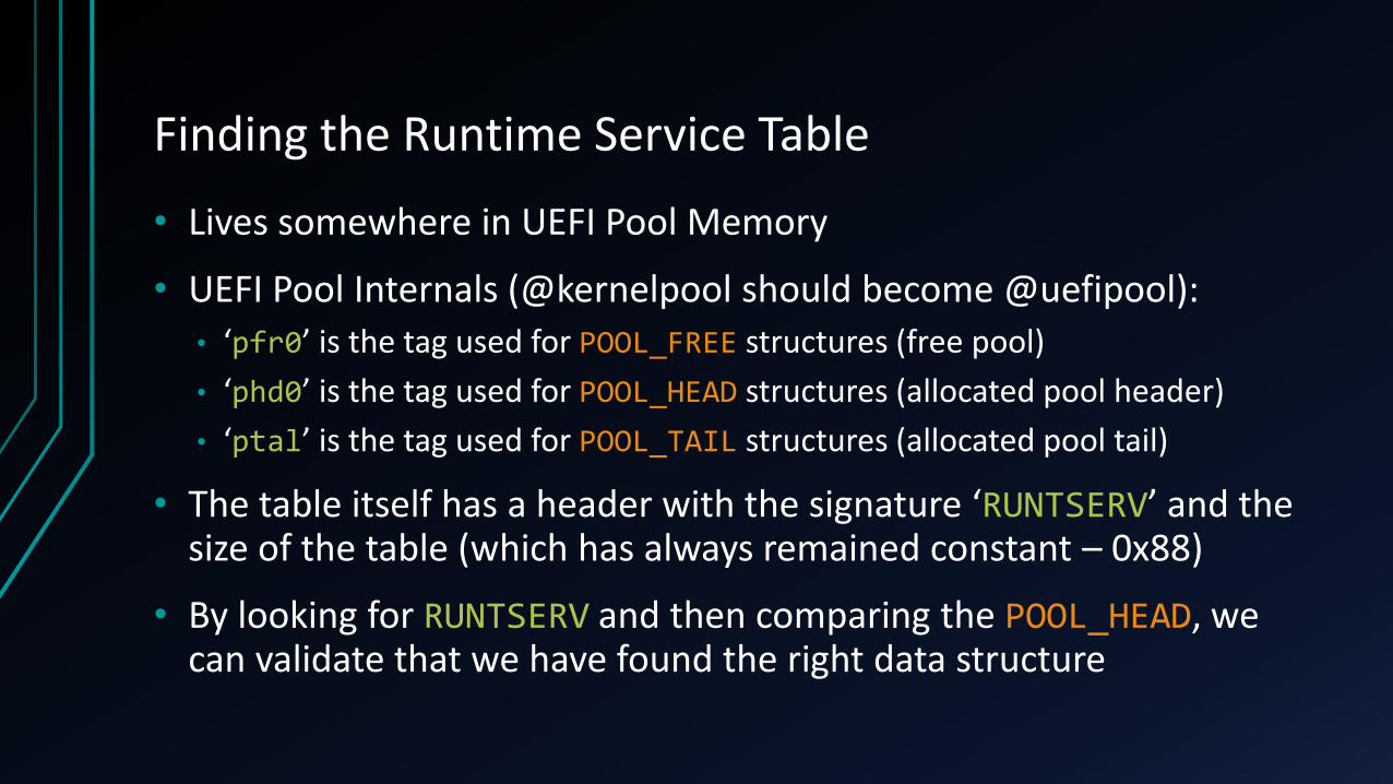
• Lives somewhere in UEFI Pool Memory
• UEFI Pool Internals (@kernelpool should become @uefipool):• ‘pfr0’ is the tag used for POOL_FREE structures (free pool)
• ‘phd0’ is the tag used for POOL_HEAD structures (allocated pool header)
• ‘ptal’ is the tag used for POOL_TAIL structures (allocated pool tail)
• The table itself has a header with the signature ‘RUNTSERV’ and the size of the table (which has always remained constant – 0x88)
• By looking for RUNTSERV and then comparing the POOL_HEAD, we can validate that we have found the right data structure

Windows Treatment of UEFI Runtime Services
• First, Windows takes the UEFI Runtime Services Table and creates a new copy of all the functions in a different location of virtual memory
• OslFwpVirtualizeRuntimeServices in the Boot Loader
• If Virtual Secure Machine (VSM) + Device Guard are enabled, the range of virtual addresses is mapped in VSM’s VTL 1 if pages are not W^X
• Will run UEFI Runtime code in VTL 1 to protect it from Ring 0 attacks
• Enabling IOMMU/VT-d will make VTL 1 memory invisible to DMA as well
• But if memory is W^X, it runs in VTL 0 – such as on Surface Pro 4

Windows Treatment of UEFI Runtime Services (part 2)
• The new pointers to the UEFI Runtime Services are passed in the Loader Block structure to the kernel, which sends it to the HAL
• Instead of making the entire table available, the HAL handpicks which runtime services it chooses to use and exposes them under HalEfiRuntimeServicesBlock
• Get/SetTime
• Get/Set/GetNext/QueryVariable(Name/Info)
• ResetSystem
• Windows 10: Update/QueryCapsule(Capabilities)
• HalEfiRuntimeServicesTable points to this, or to HalpIumEfiWrapperTable in the VSM/DeviceGuard VTL1 case
Patching the UEFI Runtime Table
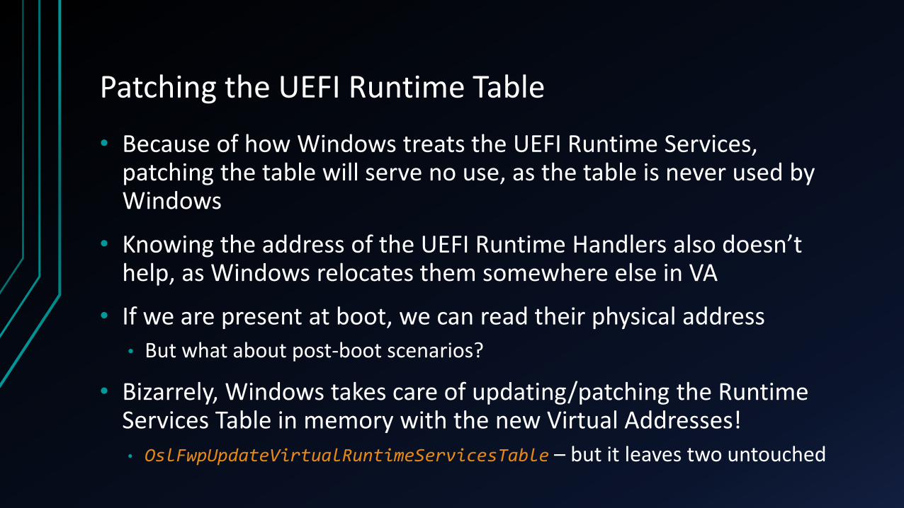
• Because of how Windows treats the UEFI Runtime Services, patching the table will serve no use, as the table is never used by Windows
• Knowing the address of the UEFI Runtime Handlers also doesn’t help, as Windows relocates them somewhere else in VA
• If we are present at boot, we can read their physical address
• But what about post-boot scenarios?
• Bizarrely, Windows takes care of updating/patching the Runtime Services Table in memory with the new Virtual Addresses!
• OslFwpUpdateVirtualRuntimeServicesTable – but it leaves two untouched

UEFI Runtime Service Table in UEFI Pool70 68 64 30 01 00 00 00 06 00 00 00 00 00 00 00 = ‘phd0’, EfiRuntimeServicesData
B0 00 00 00 00 00 00 00 52 55 4E 54 53 45 52 56 = 0xB0 bytes, ‘RUNTSERV’
28 00 02 00 88 00 00 00 3A AA D8 31 00 00 00 00 = 0x88 bytes (+0x18+0x10 = 0xB0)
24 60 BC EE FF FF FF FF 20 62 BC EE FF FF FF FF = Get/SetTime
80 64 BC EE FF FF FF FF 94 66 BC EE FF FF FF FF = Get/SetWakeupTime
24 A7 4D 7A 00 00 00 00 84 A6 4D 7A 00 00 00 00 = SetVirtualAddressMap/Convert
78 3D BD EE FF FF FF FF FC 3D BD EE FF FF FF FF = Get(Next)Variable(Name)
64 89 B9 EE FF FF FF FF B0 7A BA EE FF FF FF FF = SetVariable/GetNextHighMono
30 4F B9 EE FF FF FF FF E0 A5 BC EE FF FF FF FF = ResetSystem/UpdateCapsule
90 A7 BC EE FF FF FF FF 40 47 BD EE FF FF FF FF = QueryCapsuleCaps/VariableInfo
70 74 61 6C 00 00 00 00 B0 00 00 00 00 00 00 00 = ‘ptal’, 0xB0 bytes
Patching the Code
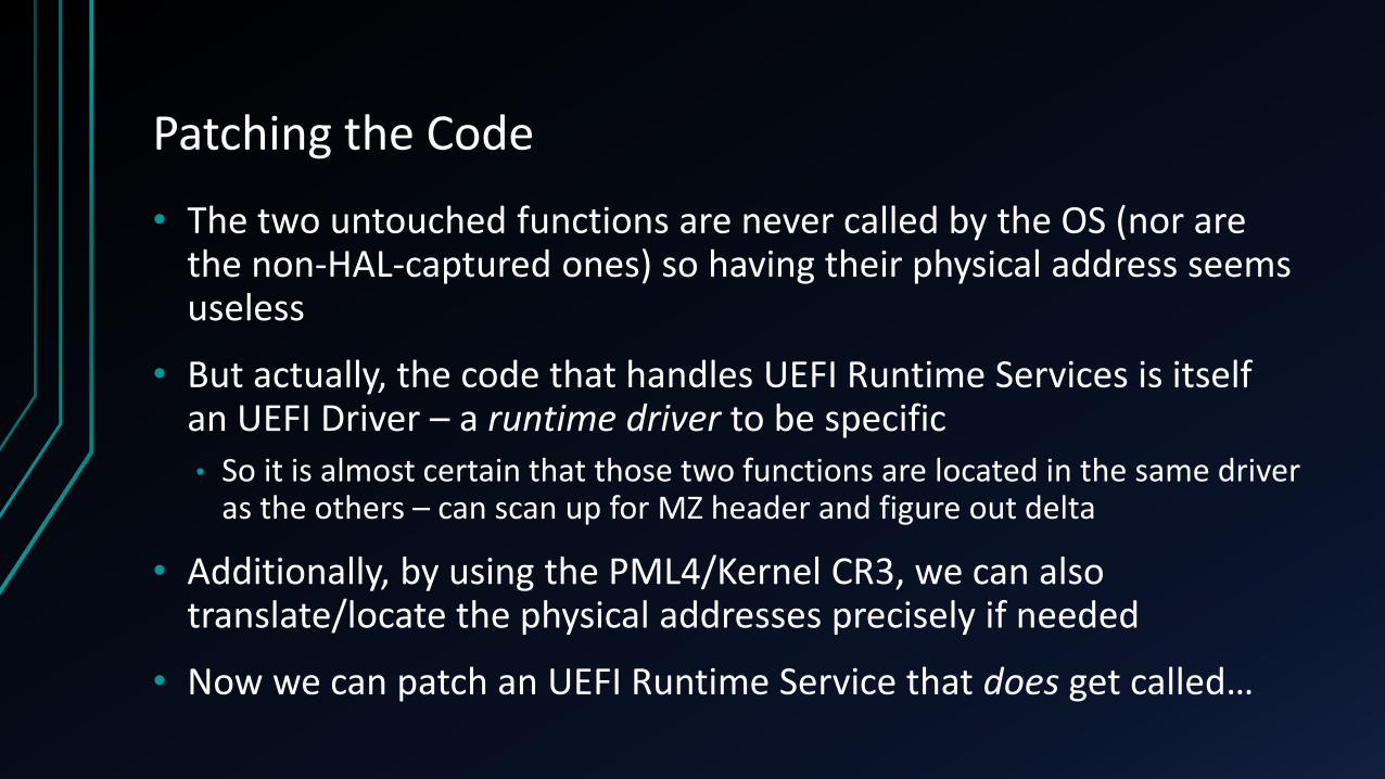
• The two untouched functions are never called by the OS (nor are the non-HAL-captured ones) so having their physical address seems useless
• But actually, the code that handles UEFI Runtime Services is itself an UEFI Driver – a runtime driver to be specific• So it is almost certain that those two functions are located in the same driver
as the others – can scan up for MZ header and figure out delta
• Additionally, by using the PML4/Kernel CR3, we can also translate/locate the physical addresses precisely if needed
• Now we can patch an UEFI Runtime Service that does get called…

Getting the Call…
• Unfortunately, Windows does not seem to have a non-admin controllable way to force the triggering of an UEFI Runtime Call
• Accessing the BCD, or Firmware Environment Variable APIs would… but these require privileged accounts
• That being said, there are scheduled tasks and various other background system activities done by services, which do cause BCD access
• MemoryDiagnostic Service called periodically
• WMI BCD Provider called by Windows Defender
• VSS (Volume Snapshot) Provider called by System Restore (periodically)

ConclusionPARTING THOUGHTS

Mitigations & Recommendations
• Run Windows 10 with Hyper-V Enabled
• Preferably, run UEFI firmware with HSTI & W^X Runtime Memory
• Using bcdedit /set firstmegabytepolicy useall will make location of Low Stub slightly harder to guess (no longer likely to be at 0x1000)
• Do not use “Always Enable” in Intel Thunderbolt Software on Bridge Devices• This will hide devices behind the bridge when later inserted/modified
• Do not disable Thunderbolt Security in your UEFI Settings• Do not enable Thunderbolt at boot unless strictly necessary
• Do not enable “Always Trust Dell Dock” #fail
Greetz, Shutouts, Kudos!
• Thank you to both Joe Fitzpatrick and Ulf Frisk without whom this research would not have been possible• They discovered the USB 3380 and DMA capabilities
• Ulf’s awesome pcileech utility avoided need to write my own
• Both responded to my constant Twitter harassment
• & of course Snare & Trammel Hudson for their earlier work
• Thanks to Michelle Bergeron for being 1st USB Type-C guinea pig
• Amazing Job Recon Organizers!!!
• See you some other time to talk about the Surface Aggregator Module (SAM) and bringing Apple SMC Persistence to Surface Pro 4

The End – Q & A