get-7002d - ge industrial systems
TRANSCRIPT

GE Consumer & IndustrialElectrical Distribution
imagination at work
Spectra RMS™
Molded Case Circuit Breakers

Contents Pages
Spectra RMS™ at a glance . . . . . . . . . . . . . . . . . . . . . . . . . . . . . . . . . . . . . . .1Spectra RMS™ features and benefits overview . . . . . . . . . . . . . . . . . . . .3Spectra RMS™ molded case circuit breakers . . . . . . . . . . . . . . . . . . . . . .6Spectra RMS™ Mag-Break® motor circuit protectors . . . . . . . . . . . . . .8Spectra RMS™ molded case switches . . . . . . . . . . . . . . . . . . . . . . . . . . .10Accessories . . . . . . . . . . . . . . . . . . . . . . . . . . . . . . . . . . . . . . . . . . . . . . . . . . .12Electrical data . . . . . . . . . . . . . . . . . . . . . . . . . . . . . . . . . . . . . . . . . . . . . . . . .19Factors affecting current ratings of installed devices . . . . . . . . . . . .22Interrupting ratings . . . . . . . . . . . . . . . . . . . . . . . . . . . . . . . . . . . . . . . . . . . .27Spectra RMS™ trip unit . . . . . . . . . . . . . . . . . . . . . . . . . . . . . . . . . . . . . . . . .31Physical data . . . . . . . . . . . . . . . . . . . . . . . . . . . . . . . . . . . . . . . . . . . . . . . . . .33Outline drawings . . . . . . . . . . . . . . . . . . . . . . . . . . . . . . . . . . . . . . . . . . . . . .34Guide Form Specifications . . . . . . . . . . . . . . . . . . . . . . . . . . . . . . . . . . . . .48

1
Spectra RMS™ at a glance
¬ 2 Pole Device in 3 Pole Frame SE MCP avail w/ 3 & 7 amp rating plugs® Spectra E Frame IEC ratings vary by ampere rating - consult table 31.1 for detail¯ 65/21 for SKL12° 42/16 for SKL12± 70/25 for SKP12
All frames are available as molded case circuit breakers, motor circuit protectors and molded case switches. All frames accept the following common accessories and modifications:• Shunt Trip • Mechanical Interlocks (3-pole)• Undervoltage Trip • Handle Padlock Attachment• Auxiliary Switches • Plug-in Base• Bell Alarm Switch • Standard Lugs• Motor Operator • Optional Lugs• Handle Operators
Characteristics
Spectra E Frame Spectra F Frame Spectra G Frame Spectra K FrameSED SEH SEL SEP SFH SFL SFP SGD SGH SGL SGP SKH SKL SKP
Poles 2, 3¬ 2, 3¬ 2, 3¬ 2, 3¬
Frame Rating (amperes) 150 250 600 1200Current Range (amperes) 15 - 150 70 - 250 125 - 600 300 - 1200
InterruptingRatings
UL/CSA Rating(kA RMS)
(50/60 hz AC)
240Vac 18 65 100 200 65 100 200 65 65 100 200 65 100 200480Vac 18 25 65 100 35 65 100 – 35 65 100 50 65 100600Vac 14 18 25 25 22 25 25 – 25 65 65 25 42 65
IEC 947-2Rating (50/60
hz AC)
220-240Vac(Icu/Ics)
18/9® 65/33® 100/50® 200/100® 65/33 100/50 200/100 – 65/33 100/50 200/100 65/16 100/25 140/35
380-415Vac(Icu/Ics)
14/7® 35/17® 65/33® 100/50® 35/17 65/33 100/50 – 25/13 65/33 100/50 50/13 65/16¯ 85/25±
500Vac (Icu/Ics) 14/7® 25/12® 40/20® 50/25® 25/12 40/20 65/33 – 18/9 35/18 50/25 25/13 42/21° 50/25690Vac (Icu/Ics) – – 5/5® 10/5® – 14/7 18/9 – – 14/7 18/9 – 14/14 18/18
Ratings/Markings
CE 3 3 3 3
HACR 3 3 3 3
Reverse Feed 3 3 3 3
SWD (15 - 20A) 3
HID (15 - 50A) 3
Current Limiting SEL, SEP SFL, SFP SGL, SGP100% Rated SGH. SGL, SGP SKH. SKL, SKP
Enclosures
General Purpose (NEMA Type 1) 3 3 3 3
Rain-Tight (NEMA Type 3R) 3 3 3 3
Dust-Tight (NEMA Type 12) 3 3 3 3
Water-Tight (NEMA Type 4/4X) 3 3 3
PanelConnections
A-Series (Main) 3 3 3 3
A-Series (Branch) (AD) 3
A-Series (Subfeed) (AD, AE) 3 3
Spectra (Main) 3 3 3
Spectra (Branch) 3 3 3 3
SCP Plus (Branch) 3 3
CCB (Branch) 3 3
Envelope
Dimensions(inch/mm)
H 6.31 (160) 10.12 (257) 10.09 (256) 15.50 (394)W 4.12 (105) 4.12 (105) 5.50 (140) 8.25 (210)D 3.38 (86) 3.81 (97) 3.81 (97) 5.50 (140)
Weight (3 pole - max frame rating) (lbs) 5.65 9.15 15.85 47.6

2
GE’s Spectra RMS™ circuit breaker line pioneered the use of interchangeablerating plugs and universal internal accessories. With the superior performancecharacteristics needed to meet your most demanding applications, rounded outby a complete line of OEM accessories, we are confident that the Spectra RMSline of circuit breakers, motor circuit protectors and molded case switches willbe the preferred product for most of your commercial, industrial and OEMapplications.
Universal Bell Alarm Interchangeable Rating Plugs
Universal Undervoltage Release
Universal Auxiliary Contacts
Universal Shunt Trip
Snap-in Lugs
• True RMS current sensing technology provides superior circuit protection.The electronic trip unit accurately monitors and responds to overcurrentconditions without the hassle of nuisance trips, even for non-sinusoidalloads such as SCR drives, welders, arc furnaces, computer power suppliesand HID lighting.
• Higher IC ratings. Ratings to 100kA@480V without fuses – and withoutchanging from traditional GE breaker sizes.
• Current limiting by design. Spectra SE, SF and SG frames provide excep-tional equipment protection with less system stressing.
• Front-mounted internal accessories and rating plugs make reverse feedingpossible on all frames.
• Better packaging density delivers more amps per cubic inch. The SpectraSF Frame offers up to 250A protection and the Spectra G Frame up to600A protection in a 4X wide frame, compared to the 6X wide J Frame.

3
Spectra RMS™
Features and benefits overview
Interchangeable rating plugsThe ampere rating of the Spectra RMS™ family of circuitbreakers and MagBreak® motor circuit protectors is establishedvia an interchangeable rating plug located on the face of theframe. To change the ampere rating, simply remove theexisting rating plug and “snap in” a new one (up to the maxi-mum ampere rating of the frame). The unique accept/rejectfeature prevents installing an incompatible rating plug. Therating plugs are a fraction of the size of traditional thermalmagnetic replaceable trip units. A wide array of rating plugsis offered for each frame size (see Table 5.1).
Field-installed breaker accessoriesEach Spectra RMS circuit breaker accepts a full range ofinternal accessories, including a wide array of shunt trip andundervoltage release devices as well as bell alarm and auxiliary switches. These accessories are UL Listed for fieldinstallation and install in minutes without the need toremove the breaker cover. The best feature is that theseinternal accessories are common across all frame sizes – asimplified design approach that saves you time and money.
Table 3.1 Spectra RMS frame dimensions
¬ 10.49 without lugs. For detailed outlines, refer to pages 36-39.
Important space savings are built into each Spectra RMS circuit breaker. Envelope dimensions for each frame areshown in Table 3.1. Accessory leads exit from the right and
Frame Maximum AmpereDimensions (in.)
H W DSE 7, 30, 60, 100 & 150 6.31 4.12 3.38SF 250 10.12 4.12 3.81SG 400 & 600 13.62¬ 5.50 3.81SK 800 & 1200 15.50 8.25 5.50
Fig. 3.1 Typical range of rating plugs SF Frame, 70-250 amps shown
Fig. 3.2 View of SG Frame breaker with accessory pouches open, accessories displayed

4
left sides of the breakers (see Figure 4.1). Each Spectra RMSbreaker has built-in channels along the sides and rear of theframe to allow the accessory leads to lie below the surfaceof the frames (see Figure 4.2). No additional space is requiredbetween adjacent breakers to accommodates accessoryleads in group-mounted applications. The rear channel alsoallows accessory leads to be routed behind a panel-mount-ed unit without the need for stand-off hardware.
Application focused time-current characteristicsThe tracking short-time function provided by Spectra RMScircuit breakers is shown in Figure 4.3. Long-time and instanta-neous-trip points establish the breaker’s full load and severeovercurrent trip characteristics.
In feeder circuit applications, the tracking short-time functionbacks up downstream devices such as fuses or starter over-loads with time for them to clear before the breaker opens.For branch circuit applications, the Spectra RMS breaker pro-vides added, tighter protection not available in any otherstandard 150-amp frame breaker.
Higher interrupting capacitiesModern power distribution systems require protectivedevices with higher interrupting capacities. Each SpectraRMS circuit breaker is available in multiple IC ranges with100 kA rms symmetrical @ 480Vac being the maximuminterrupting tier. Complete UL489, CSA C22.2, and IEC 947-2interrupting ratings are detailed in Tables 28.1 and 29.1.
Fig. 4.1 View of typical breaker with undervoltage release leads broughtout on left side and auxiliary switch leads brought out on right side
Fig. 4.2 Undervoltage release leads run behind back of breaker
.5 1 10 100 1000 10000.01
.1
1
2
345
7
10
100
1000
TIM
E–
SECO
ND
S
LONG TIME
TRACKING SHORT TIME
INSTANTANEOUS
CURRENT – AMPERES x 10
PICKUP
DELAY
PICKUP
DELAY
Fig. 4.3 Typical time-current curve for Spectra RMS circuit breaker

5
Spectra RMS Mag-Break product lineThe Spectra RMS Mag-Break motor circuit protector offersthe precision and ambient insensitivity of GE’s solid-statetripping system in a highly cost-effective motor circuit pro-tective device. The same interchangeable rating plugs areused to define the instantaneous setting ranges of eachunit. The instantaneous-trip point and tracking short-timecharacteristic is adjustable over approximately a 5-to-1range. Figure 5.1 illustrates time current curve features of thetypical Mag-Break unit shown in Figure 8.1.
As an example of the flexibility of the Spectra RMS Mag-Breakline, consider a 250A SF frame with 70A and 250A ratingplugs, the nominal instantaneous pickup range is 205 (min.setting) to 700A (max. setting) with a 70A plug to a range of740A – 2500A with a 250A plug. (See Table 21.2 for details.)
Spectra RMS molded-case switch product lineThe Spectra RMS circuit breaker family also has a full line ofcompact, economical circuit disconnect devices. Spectra RMSmolded case switches have seven current ratings from 100amps to 1200 amps. In the event of mis-application or severeovercurrent, the contacts of these devices will open on anon-adjustable, high-set, instantaneous basis, preventingdamage to the molded case switch (see Table 10.1 for values).Downstream conductor and load protection must be providedby other devices with adequate interrupting capacity.
Molded case switches, by definition, do not provide any overcurrent protection. The short circuit withstand ratings arelisted in Table 29.2.
Table. 5.1 Spectra RMS Circuit Breaker and Mag-Break motor circuit protectorrating plug current ratings
¬ The 7-amp frame and the 3A and 7A rating plugs are used only with the SpectraRMS Mag-Break motor circuit protector.
Spectra RMS circuit breaker, Mag-Break and moldedcase switch product line
Table. 5.2 Spectra RMS maximum frame ratings (amperes) & construction summary
¬ Adjustable instantaneous/short-time with changeable long-time (via rating plug) Adjustable instantaneous/short-time® Fixed high-set instantaneous override
Frame Circuit Breaker¬
(2 & 3 Pole)
Motor CircuitProtector
(3 Pole Only)
Molded CaseSwitch®
(3 Pole Only)
SE-Frame
– 7 –30 30 –60 60 –
100 100 100150 150 150
SF-Frame 250 250 250
SG-Frame400 400 400600 600 600
SK-Frame800 800 800
1,200 1,200 1,200
Frame MaximumAmperes Available Rating Plugs, Amperes
SE-Frame
7¬ 3 & 730 15, 20, 25 & 3060 40, 50 & 60
100 70, 80, 90 & 100150 110, 125 & 150
SF-Frame 250 70, 90, 100, 110, 125, 150, 175, 200, 225 & 250
SG-Frame400 125, 150, 175, 200, 225, 250, 300, 350 & 400600 250, 300, 350, 400, 450, 500 & 600
SK-Frame800 300, 400, 500, 600, 700 & 800
1,200 600, 700, 800, 900, 1000 & 1200
.5 1 10 100 1000 10000.01
.1
1
10
100
1000
TIM
E–
SECO
ND
S
TRACKING SHORT TIME
INSTANTANEOUS
CURRENT – AMPERES x 10
PICKUP
DELAY
INST. set on MIN
INST. set on MAX
Fig. 5.1 Typical adjustability range for Spectra RMS Mag-Break motor circuit protector

6
Spectra RMS™ molded case circuit breakers
Universal rating plug conceptAll Spectra RMS circuit breakers incorporate a UL Listedinterchangeable rating plug that establishes the circuitbreaker’s ampere rating. The key advantages of the ratingplug concept are the speed and flexibility of selecting orchanging the ampere rating of the circuit breaker. Each circuitbreaker frame and sensor have multiple rating plugs thatoffer a wide range of standard ampere ratings from whichto select.
Since the installed rating plug establishes the ampere ratingof the breaker, the installer must verify the adequacy of theconnected cable and/or bus bar ampacity. The NationalElectrical Code allows cable size to be matched to theampere rating established by the rating plug.
All rating plugs have built-in accept/reject features to assurethat they are applied correctly. For example, SE-Frame SpectraRMS circuit breakers are offered in four frame ratings: 30, 60,100 and 150 amp. The 60-amp frame has three rating plugs(40-, 50- and 60-amp). Rating plugs for the 60-amp SE-Framecircuit breaker can only be used on that family of units.Conversely, rating plugs for other frames or current ratingsare not accepted by the 60-amp SE-Frame rating plug cavity.
Trip unit characteristicsSpectra RMS circuit breakers offer the application flexibility andaccurate measurement of current waveforms with harmoniccontent. In addition, SE-, SF- and SG-Frame circuit breakersincorporate true current limiting construction. All Spectra RMScircuit breakers offer IC (Interrupting Capacity) ratings up to,and including 100,000 amps, rms, symmetrical, at 480 Vacand up to 200 kA at 240 Vac.
Application flexibilityApplication flexibility is provided by adding short-time andinstantaneous trip characteristics to the long-time, time currentcurve of the solid-state trip system.
Long timeThe rating plug determines the long-time trip performance ofthe Spectra RMS circuit breaker. Spectra RMS circuit breakersare designed to carry 100% of the rating plug ampere ratingcontinuously, in open air without exceeding a 50°C tempera-ture rise at the circuit breaker terminals. At 105% to 130% ofthe rating plug ampere rating (the long-time pick-up tolerancesof the trip circuit), the circuit breaker will trip in the event of along-term overload downstream from the circuit breaker.
Short timeThe inverse-time short-time delay trip characteristic of SpectraRMS circuit breakers provides an increase in protection by
Fig. 6.1 Removal of rating plug Fig. 6.2 Typical adjustability range for Spectra RMS circuit breaker
.5 1 10 100 1000 10000.01
.1
1
10
100
1000
TIM
E–
SECO
ND
S
LONG TIME
TRACKING SHORT TIME
INSTANTANEOUS
CURRENT – AMPERES x 10

7
providing closer tracking of load-operating conditions. Theshort-time pickup function tracks the instantaneous pickupby a factor of 0.5 to 0.8, depending upon specific frame andrating plug.
InstantaneousThe trip setting adjustment knob controls the settings ofboth short-time and instantaneous-trip characteristics. Whenthe adjustment knob is set in the “Max” position, the breakerwill trip instantaneously between 10 to 13 times (dependingupon breaker frame) the long-time trip rating (i.e., rating plugamp rating). This provides sufficient margin to avoid nuisancetripping when energizing inductive loads such as motors ortransformers.
The nominal instantaneous pickup values, in amps, are listedon each rating plug as shown in Figure 7.1.
Spectra RMS current limiting constructionSpectra RMS circuit breakers continue the GE standard ofrugged construction and the use of heavy silver-alloy contacts.The low physical mass of the contact arms in the SE, SF andSG Frame Spectra RMS circuit breakers, coupled with areverse current loop, result in true current limiting performancewithout compromising breaker life.
When short circuit current flows through the lower and uppercontact arms of the circuit breaker, a strong magnetic field isproduced by the fault current. Since the fields are opposing,forces proportional to the square of the current act to “blow-open” the movable contact arms. The higher the fault current,the higher the contact separation forces. During maximumfault conditions, contact separation typically occurs within aquarter of one cycle, and the arc is fully quenched withineight milliseconds.
Peak let-through current, illustrated in Figure 7.2, is held toless than 45% of the maximum available peak fault current,resulting in a tremendous reduction in the amount of energythat the fault delivers to the conductors and the connected load.
If current limiting performance is required, choose betweenSpectra SEL, SEP, SFL, SFP, SGL and SGP catalog numbers.
1/2 cycleIA
IB
IC
Peak let thru – 29.8 kA
Available Peak Current – 223.5 kAVoltage – 485 VPower Factor – 18.1%Peak let thru – 37.7 kA
Peak let thru – 17.3 kA
Fig. 7.1 Rating plug label Fig. 7.2 Typical current limiting performance

8
Spectra RMS™ Mag-Break®
motor circuit protectors
Interchangeable rating plugSpectra RMS Mag-Break motor circuit protectors use thesame snap-in rating plugs as fully configured (long-time tripfunction) Spectra RMS circuit breakers. Each rating plugdefines the range of instantaneous-trip settings available tothe circuit breaker through its trip setting adjustment.
Trip setting adjustmentThe solid-state instantaneous-trip circuitry of the SpectraRMS Mag-break motor circuit protectors has a single, multi-position adjustment at the front of each breaker. Changes insettings vary the instantaneous-trip and tracking short-timecharacteristics. The Mag-Break motor circuit protectors differfrom a fully configured circuit breaker by only providing aninstantaneous and tracking short-time trip function.
Accessory pocketsSpectra RMS Mag-Break motor circuit protectors have thesame accessory pockets and use the same internal accessoriesas Spectra RMS circuit breakers. This important capabilityallows field modification of Mag-Break units with shunt trip,undervoltage release, bell alarm or auxiliary switch accessories,in any combination, without affecting the UL Listing status.
Spectra RMS rating plugsUse of the same UL Listed interchangeable rating plugs forboth Mag-Break and fully configured Spectra RMS circuitbreakers expands the flexibility of the entire Spectra RMSfamily of products. The advantages of interchangeable ratingplugs with Spectra RMS circuit breakers are inherent to SpectraRMS Mag-Break units, which permit wider ranges of motorratings to be protected by a given breaker frame size.
Spectra RMS Mag-Break trip unit characteristicsSpectra RMS Mag-Break motor circuit protectors providepositive, reliable and cost-effective instantaneous, withtracking short-time overcurrent protection to those circuitswhere long-time overload protection is supplied by thermalor solid-state overload devices.
Motor circuit short circuit protectionWhen a squirrel-cage induction motor is energized, a highvalue of magnetizing inrush current flows for the first fewcycles, followed by a substantial reduction in current flowwhile the motor accelerates to its rated speed. When plottedon a time current curve, the motor current has three distinctregions – for the first five to eight cycles, typical magnetizinginrush currents are approximately ten times the full-loadmotor current (but can be much greater for high efficiencymotors). Between 0.10 and 10 seconds, the magnetizinginrush current drops to approximately five to six time thefull-load motor current. After approximately 10 seconds, themotor reaches its full speed and the current quicklydecreases to the full-load current of the motor.
Optimum motor protection for the first two regions of themotor time current plot would involve a two-tiered protectionscheme with a high value of current tolerated for a fewcycles, followed by a lower, sustained trip setting.
This is exactly the protection that is offered by the Mag-Breakmotor circuit protector. This two tiered protection schemeprevents nuisance tripping due to magnetizing inrush current,without compromising superior short circuit protection duringmotor acceleration. Protection for the third region of the motortime current plot is accomplished via the motor starter’soverload relay.
Figure 8.2 illustrates this motor protection scheme. Curve Aand the shaded area directly above it represents the region
Fig. 8.1 SE150 Spectra RMS Mag-Break motor circuit protector
.5 10 100 1000 10000.01
.1
1
10
100
1000
CURRENT – AMPERES x 10
TIM
E–
SECO
ND
S
CURVE A
CURVE DCURVE C
CURVE B
Fig. 8.2 Motor circuit protection using Mag-Break motor circuit protectors
A – Motor damageB – Motor overloadC – Motor startD – Mag-Break motor
circuit protector

9
of operation that will produce permanent damage to eitherthe motor, its feeder conductors or both. Curve B representsthe trip characteristics of the motor starter’s overload relay,which provides both long-term overload and stall protectionbut does not protect the system from short circuits in eitherthe motor or its feeder conductors. Curve C is a plot of themotor current during a worst-case start (e.g., low line voltage,highest load torque, etc.). Curve D represents the trip charac-teristics of the Mag-Break motor circuit protector — with thisaddition, the motor and its feeder conductors are now fullyprotected against short circuits.
Spectra RMS Mag-Break motor circuit protector ratingsTable 9.1 lists rating plugs available for each Mag-Breakmotor circuit protector frame size. Instantaneous trip settingsare listed under electrical data on page 21 and UL interruptingratings are shown on page 28 (per UL 489, motor circuit protectors are not marked with interrupt ratings). Except for3 amp and 7 amp plugs, all other rating plugs are used inboth circuit breaker and Mag-Break motor circuit protectors.
Table. 9.1 Spectra RMS Mag-Break motor circuit protector and rating plug current ratings
¬ The 7-amp frame and the 3A and 7A rating plugs are used only with the Spectra RMS Mag-Break motor circuit protector.
Frame MaximumAmperes
Available Rating Plugs, Amperes
SE-Frame
7¬ 3 & 730 15, 20, 25 & 3060 40, 50 & 60
100 70, 80, 90 & 100150 110, 125 & 150
SF-Frame 250 70, 90, 100, 110, 125, 150, 175, 200, 225 & 250
SG-Frame400 125, 150, 175, 200, 225, 250, 300, 350 & 400
600 250, 300, 350, 400, 450, 500 & 600
SK-Frame800 300, 400, 500, 600, 700 & 800
1,200 600, 700, 800, 900, 1000 & 1200

10
Spectra RMS™ molded case switches
ConstructionThe family traditions of ruggedness and dependability arecontinued in the Spectra RMS molded case switch line. Theseunits provide a circuit disconnect function using the compactnessof molded case circuit breaker construction. The operatinghandle actuates all three poles of the switch using the sameinternal components as the Spectra RMS circuit breakersand Mag-Break units.
Termination lugsSnap-in termination lugs used with SE- and SF-Frame SpectraRMS circuit breakers are used interchangeably in SpectraRMS molded case switches. SG- and SK-Frame molded caseswitches use the same bolt-on termination lugs used withSpectra RMS circuit breakers.
External accessoriesThe full range of external circuit breaker accessories offeredfor use with Spectra RMS circuit breakers and Mag-Breakmotor circuit protectors, are available for molded caseswitches. Figure 10.1 shows a Spectra RMS molded caseswitch. In addition, plug-in bases, motor-operated mechanisms,mechanical interlocks and the full complement of externalhandle operators (STDA, TDR and TDM) are available for usewith Spectra RMS molded case switches.
Fixed-trip settingThe Spectra RMS molded case switches are equipped with afixed Hi-set instantaneous trip setting whose values areshown in Table 10.1.
Table. 10.1 Spectra RMS molded case switch fixed trip setting
The 7-amp frame and the 3A and 7A rating plugs are used only with the Spectra RMSMag-Break motor circuit protector.
Spectra RMS molded case switch applicationsMolded case switches are inherently horsepower-rated. Byvirtue of the UL489 six-times-rated current overload test,they can be used as motor circuit disconnects where overload and short circuit protection are provided by otherprotective devices.
A common application of Spectra RMS molded case switchesis illustrated in Figure 10.2, which shows a system containingthree branch circuits.
Branch Circuit 1 uses a Spectra RMS Mag-Break motor circuitprotector, in conjunction with the overload devices of themotor starter, to protect the motor and the conductors ofthat branch circuit. Branch Circuits 2 and 3 use fully config-ured Spectra RMS circuit breakers to provide instantaneous,short-time and long-time protection for both branch-circuitconductors and loads.
Molded CaseSwitch Frame
MaximumAmperes
Fixed Trip Setting RMS Amperes Nominal ±20%
SE-Frame100
2,100150
SF-Frame 250 2,450
SG-Frame400 5,600600 6,000
SK-Frame800 12,600
1,200 12,700
Fig. 10.1 Spectra RMS molded case switch Fig. 10.2 Spectra RMS molded case application

11
Protection of the short bus and feeder between the SpectraRMS molded case switch and the bus in this figure is provid-ed by a properly rated breaker.
Spectra RMS molded case switches are excellent circuit dis-connect devices for those applications where both theadvantages of molded case switch construction are desired,and where the available short circuit current is less than theswitch withstand rating as defined in Table 29.2.
All Spectra RMS molded case switches are UL Listed andtested per UL Standard 1087 for molded case switches. Theshort circuit withstand ratings are based upon three cycletests. Thus the UL Listed upstream overcurrent protectivedevices (i.e., low-voltage power circuit breakers equippedwith instantaneous-trip functions, insulated-case circuitbreakers, molded case circuit breakers or fuses) can be usedin conjunction with molded case switches.
Table. 11.1 Spectra RMS molded case switch current ratingsThree-pole, 600-Vac
Switch Frame Type Maximum Frame Ampere
SE-Frame SEDA 100 & 150SF-Frame SFDA 250SG-Frame SGDA 400 & 600SK-Frame SKDA 800 & 1200

12
Accessories
Internal accessoriesSpectra RMS™ internal accessories are common to all productsin the Spectra RMS product family, including circuit breakers,Mag-Break motor circuit protectors and molded case switches.They are interchangeable between frame sizes, i.e., the 24Vdc/24 Vac shunt trip – SAST3 – can be installed in any of thefour basic frames from the type SE150 to the type SK1200.In addition, Spectra RMS internal accessories are designedto be installed in pockets accessible from the front of the circuit breaker.
No disassembly of the circuit breaker case is required.
These unique characteristics – interchangeability, commonalityand installation without violation of case integrity – providethe user with the optimum combination of reliability, stan-dardization and parts reduction. All Spectra RMS accessoriesare UL Listed for field installation.
The left-hand circuit breaker accessory pocket accepts anactuator, shunt trip or undervoltage release plus a bell alarmswitch. The right-hand pocket is used for auxiliary switches.All accessories are supplied with 36-inch long, #18AWG 105°C300V minimum insulated leads. Side and rear wire channelsallow accessory leads to be led to the left, right or back ofthe breaker within the dimensions of the breaker envelope.
Shunt trip
The shunt trip is used to trip (open) the circuit breaker byremote control. Spectra RMS shunt trips are UL Listed forfield installation, meeting UL requirements for operation at55% of rated ac voltage and 75% of rated dc voltage for useon ground fault systems.
A momentary application of control power is recommendedto activate the shunt trip coil. An integral pulsing circuit isused within the shunt trip’s electronics to prevent the coilfrom being damaged from maintained control power. Ifmaintained control power (latching relay) is used in lieu ofmomentary application of control power, use a bell alarmcontact in series with the shunt trip’s control power for theSE/SF breakers or an auxiliary switch in series with the shunttrip’s control power for the SG/SK breakers. Failure to wire
the bell alarm or aux switch in series could result in a 1 to 2second delayed response if the breaker is re-closed whilethe shunt trip is continuously energized.
Electrical dataTable. 12.1 Shunt trip device electrical characteristics
Fig. 12.1 Wiring diagram, shunt trip
Undervoltage release
The undervoltage release trips the circuit breaker when controlvoltage drops to less than 35% to 70% of its rated voltage.Optional time delay units from 100 to 1,000 millisecondsallow the user to minimize nuisance tripping. The time delaymay be switched off to provide an instantaneous undervoltagetrip. In the event an attempt is made to reclose the circuitbreaker while the undervoltage condition is still present, theundervoltage release device will prevent breaker contactclosure; i.e., it’s a “kiss-free” design.
The “kiss-free” feature requires that if a breaker is in the OFFposition and the toggle handle is being held in the off position,such as by a motor operated mechanism, and a trip commandfrom a shunt trip or undervoltage release (UVR) causes thebreaker mechanism to trip, the following steps must becompleted to turn on the breaker:1. restore control power to UVR if applicable2. move toggle handle to ON position (breaker will not close)3. move handle back to reset (OFF) position4. move handle to ON to close
Black
Black
CatalogNumber
Rated Nominal Voltage Current, mAAC DC Inrush Cont.
SAST1 120 125 500 6SAST2 240 250 400 5SAST5 — 12 1000 800SAST3 24 24 300 10SAST4 48 48 300 1
13
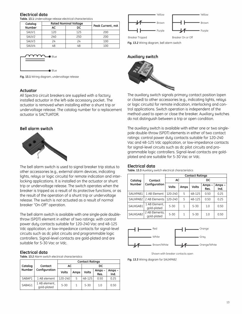
Electrical dataTable. 13.1 Undervoltage release electrical characteristics
Fig. 13.1 Wiring diagram, undervoltage release
ActuatorAll Spectra circuit breakers are supplied with a factoryinstalled actuator in the left-side accessory pocket. Theactuator is removed when installing either a shunt trip orundervoltage release. The catalog number for a replacementactuator is SACTUATOR.
Bell alarm switch
The bell alarm switch is used to signal breaker trip status toother accessories (e.g., external alarm devices, indicatinglights, relays or logic circuits) for remote indication and inter-locking applications. It is installed on the actuator or shunttrip or undervoltage release. The switch operates when thebreaker is tripped as a result of its protective functions, or asthe result of the operation of a shunt trip or undervoltagerelease. The switch is not actuated as a result of normalbreaker “On-Off” operation.
The bell alarm switch is available with one single-pole double-throw (SPDT) element in either of two ratings: with controlpower duty contacts suitable for 120-240 Vac and 48-125Vdc application, or low-impedance contacts for signal-levelcircuits such as dc pilot circuits and programmable logiccontrollers. Signal-level contacts are gold-plated and aresuitable for 5-30 Vac or Vdc.
Electrical dataTable. 13.2 Alarm switch electrical characteristics
Fig. 13.2 Wiring diagram, bell alarm switch
Auxiliary switch
The auxiliary switch signals primary contact position (openor closed) to other accessories (e.g., indicating lights, relaysor logic circuits) for remote indication, interlocking and con-trol applications. Switch operation is independent of themethod used to open or close the breaker. Auxiliary switchesdo not distinguish between a trip or open condition.
The auxiliary switch is available with either one or two single-pole double-throw (SPDT) elements in either of two contactratings: control power duty contacts suitable for 120-240Vac and 48-125 Vdc application, or low-impedance contactsfor signal-level circuits such as dc pilot circuits and pro-grammable logic controllers. Signal-level contacts are gold-plated and are suitable for 5-30 Vac or Vdc.
Electrical dataTable. 13.3 Auxiliary switch electrical characteristics
Fig. 13.3 Wiring diagram for SAUXPAB2
Red
Shown with breaker contacts open
White
Brown/White
Orange
Gray
Orange/White
CatalogNumber
ContactConfiguration
Contact RatingsAC DC
Volts Amps Volts Amps –Res.
Amps –Ind.
SAUXPAB1 1 AB Element 120-240 5 48-125 0.50 0.25
SAUXPAB2 2 AB Elements 120-240 5 48-125 0.50 0.25
SAUXGAB11 AB Element,
gold-plated5-30 1 5-30 1.0 0.50
SAUXGAB22 AB Elements,
gold-plated5-30 1 5-30 1.0 0.50
Yellow
Breaker Tripped Breaker On or Off
Purple
Brown
Yellow
Purple
Brown
CatalogNumber
ContactConfiguration
Contact RatingsAC DC
Volts Amps Volts Amps –Res.
Amps –Ind.
SABAP1 1 AB element 120-240 5 48-125 0.50 0.25
SABAG11 AB element,
gold-plated5-30 1 5-30 1.0 0.50
Blue
BlueUndervoltage Release
CatalogNumber
Rated Nominal VoltagePeak Current, mAAC DC
SAUV1 120 125 200SAUV2 240 250 200SAUV3 24 24 100SAUV4 48 48 100

14
External accessories
Termination lugsTermination lugs permit easy front connection of either cop-per or aluminum-insulated conductors to the terminals ofSpectra RMS circuit breakers and molded case switches.
Figure 14.1 illustrates the snap-in lugs that are installedwithout tools in SE- and SF-Frame Spectra RMS circuitbreakers and molded case switches.
Sizes and ratingsTermination lugs are designed and tested for use with con-ductors sized on 75°C ampacity and insulated with 75°Cinsulation (or higher). Table 14.1 lists the conductor rangesfor these tinplated extruded-aluminum lugs and copper lugs.
Table. 14.1 Lug sizes and ratings for circuit breakers (including Mag-Break) andmolded case switches
¬ Includes 1/4" male spade terminal for control wire termination using UL Listed 250Series fully insulated receptacle connector
TCLK265 & TCOK265 included qty (2) lugs® TCLK365 & TCOK365 included qty (3) lugs¯ Alternate 1200A lug for SK; TCAL124 (3) 350-700 kcmil CU/AL, and TCO124
(3) 350-700 kcmil CU
Back-connected studsBack-connected studs are used in applications where cablingor bussing behind the panel is required. A mounting sub-baseis provided that mates with the Spectra RMS circuit breaker ormolded case switch and the studs. Each stud is of sufficientlength to accommodate panel thicknesses from 0.25 inches(6mm) to one inch (25mm).
Fig. 14.2 Back-connected studs
Sizes and ratingsTable 14.2 lists the back-connected studs available for thecomplete line of Spectra RMS circuit breakers, includingMag-Break devices and molded case switches. These studsare field-installed.
Table. 14.2 Back-connected line and load studs
Frame Max.Amps
Length, Back of Device Short/Long
CatalogNumberInches Millimeters
SE
502 25/32 70.6 Short TEF1
4 13/32 112.0 Long TEF2
1503 13/32 86.5 Short TEF3
5 25/32 147.0 Long TEF4
SF 2502 23/32 69.0 Short TFK1
5 31/32 151.5 Long TFK2
SG 6002 13/16 71.4 Short SGBCS1
6 1/16 153.7 Long SGBCS2
SK800 5 1/2 139.7 — TKM11
1,200 8 203.0 — TKM12
Device Catalog No.
(Qty) Wire Range (75°C Insulated Conductor)
Frame FrameAmps Copper Aluminum &
Copper Clad
SE All Frames(7A to 150A)
TCAL18 &TCAL18LV¬
(1) #12 – 3/0 AWG (1) #12 – 3/0 AWG
SF 250TCAL29 &
TCAL29LV¬
(1) #8 AWG – 350kcmil
(1) #8 AWG – 350kcmil
SG 400, 600TCLK265
&TCLK365®
(2) 2/0 – 500 kcmil or (1) #8 AWG -
600 kcmil
(2) 2/0 – 500 kcmil or (1) #6 AWG -
600 kcmil
SK800 TCAL81 (3) 3/0 - 500 kcmil (3) 3/0 - 500 kcmil
1200¯ TCAL125 (4) 250 - 500 kcmil (4) 250 - 500 kcmil
SE All Frames(7A to 150A) TC018 (1) #12 – 3/0 AWG —
SF 250 TC029 (1) #8 AWG – 350kcmil —
SG 400, 600 TCOK265,TCOK365
(2) 2/0 – 500 kcmil or (1) #8 - 600 kcmil —
SK800 TC081A (3) 250 - 500 kcmil —
1,200 TC0125 (4) 350 - 500 kcmil —
Fig. 14.1 Typical Snap-in Lug Fig. 14.2 Spectra RMS lugs

15
Plug-in mounting basesPlug-in mounting bases provide the user with another optionfor quick changeout of breaker and switch assemblies withoutdisturbing power connections. Two plug-in bases (one foreach terminal end) are required for each protective device.
An optional mounting plate is supplied at no additionalcharge when ordered with a pair of mounting bases, andprovides three important functions. The plate locates andsupports the line and load base assemblies, provides a convenient means to mount the entire assembly to a metalstructure and serves as a deadfront barrier.
Each plug-in base assembly contains all of the mountinghardware necessary to mount the base to either end of thecircuit breaker or molded case switch. Electrical spacingbetween adjacent terminals is provided by alternate long-short-long (LSL) or short-long-short (SLS) terminal assemblies.Fully configured Spectra RMS circuit breakers are availablein two-pole configurations— with the center pole missing.Consequently, base assemblies for two-pole breakers areeither short-open-short (SOS) or long-open-long (LOL). SE-,SF- and SK-Frames use horizontal studs (suffix PD1 or PD2),while SG-Frames use vertical studs (suffix PC1 or PC2). Table15.1 lists the sizes and ratings of the plug-in base assemblies.
When breakers or switches are mounted side by side, it isimportant to plan for adjacent outside poles of the twodevices to have a long-short or short-long configuration, so that adequate electrical spacing is provided betweenadjacent devices.
Table. 15.1 Plug-in mounting base
¬ Vertical stud orientation.
Motor-operated mechanisms (MOM)The MOM function uses an ac or dc motor-driven mechanismto produce rapid closing or opening. No physical modificationof the breaker or switch is needed to add the MOM. The MOMoperator slips over the operating handle of the circuit breakeror molded case switch. The MOM cover can be lifted to man-ually open or close the breaker or switch. Visual indication ofthe “On-Off” status appears on the mechanism cover.
Face-mounted mechanical interlocksMechanical interlocks are available for all Spectra RMS circuitbreakers and molded case switches. The function of themechanical interlock is to positively assure that two adjacentdevices in an assembly cannot both be in their “On” (i.e.,closed) position at the same time. However, both devices canbe “Off” (i.e., open or tripped) at the same time.
These interlocks are useful whenever control or safetyrequirements dictate an either-or energized condition down-stream of the two protective devices.
Plug-in Mounting Bases, 2 Required per BreakerOptional
Mounting PlateAmpRating
BreakerType
No. ofPoles
Horizontal StudConfigurations Catalog
NumberPD1 PD2 Catalog Number
150 SE150 3 SLS LSL TE13PD1,2 TMP1
250 SF2502 SOS LOL TF22PD1,2
TMP23 SLS LSL TF23PD1,2
600SG400
3 SLS LSL SGPC1,2¬ SMP3SG600
800 SK1200 3 SLS LSL TK83PD1A,2A TMP41,200 SK1200 3 SLS LSL TK123PD1A,2A TMP4
Fig. 15.2 Motor-operated mechanism for an SF-Frame Spectra RMS circuit breakerFig. 15.1 Plug-in mounting base

16
Table. 16.1 Mechanical interlock (face mounted)
¬ Compatible with motor operator only. SGFMI cannot be used with handle operator.
Table. 16.2 Motor-operated mechanisms, rating and electrical data
¬ All ac control power may be either 50 Hz or 60 Hz.
Handle operatorsThree different operating handles are available for use withSpectra RMS circuit breakers and molded case switches:STDA, TDM and TDR. Each provides its own unique function.Types STDA and TDM are adjustable-depth operating handles.Type TDR operating handles are rotary handles that connectdirectly to the protective device and the operating handleprojects directly through the enclosure door.
Type STDA flange handles, variable depth operatingmechanisms and accessoriesType STDA handles (Figure 16.1) are designed to meet auto-motive-duty specifications. They are NEMA 12/13 and NEMA4/4X UL recognized components. These handles can belocated on either the right-hand or left-hand flange of anenclosure and they are field-convertible for either position.
Handle mounting dimensions fit standard flanged enclosureswith depths from eight inches to 24 inches (203mm to 609mm).
Fig. 16.1 Type STDA1 flange handle
Two different handle lengths are provided. Type STDA1, 1Xhandles have a nominal length of 6 inches (152mm) andTypes STDA2, 2X handles have a nominal length of 10 inches(254mm). Both flange handles are interchangeable and aresatisfactory for use with all operating mechanisms.
The advantage to using the longer Type STDA2 handle is thereduction in the operating forces provided by the longer leverarm. Both handles permit use of up to three 3/16 to 5/16inch (4.75mm to 7.94mm) diameter padlocks. Both handlesare equipped with O-ring seals for oil-tight/dust-tight duty.
Variable depth operating mechanismsThe operating mechanism consists of two primary components:a combination mounting plate and yoke, and a drive rodthat connects the handle to the yoke mechanism.
The protective device is mounted on the plate, and the device’soperating handle slips into a slot on the front of the yoke. Themounting plates have a spring-assist feature to assure positive“On-Off” operation. Yoke stops are included to preventexcessive wear of the operating handle of the circuit breakeror molded case switch.
The standard drive rod is 3/8 inch (9.5mm) in diameter for SEand SF and 1/2 inch for SG and SK frames.
The SK frame operating mechanism (SD0M6) requires aunique flange handle, Cat. No. STDA3 pr STDA3X which cannot be used with any other operating mechanism.
Type STDA handle accessoriesFour accessories are available for use with the STDA handle
DeviceFrame
CatalogNumber
Control Power Operating TimeSeconds Recommended
FuseVoltage¬
AmpsClosing Opening
ResetInrush Running
SE
SEMOM1120 Vac 10.5 5
0.15 0.13
1 AmpTime Delay125 Vdc 13.5 4
SEMOM2 240 Vac 6.5 3SEMOM8 24 Vdc 31 15.5 2 Amp
Time DelaySEMOM9 48 Vdc 20 7
SF
SFMOM1120 Vac 10.5 5
0.15 0.13
1 AmpTime Delay125 Vdc 13.5 4
SFMOM2 240 Vac 6.5 3SFMOM8 24 Vdc 31 15.5 2 Amp
Time DelaySFMOM9 48 Vdc 20 7
SG
SGMOM1120 Vac 13.5 8.5
0.25 0.20
125 Vdc 13.5 4.5
SGMOM2240 Vac 6.5 3250 Vac 8 2.5
SGMOM8 24 Vdc 33 19.5SGMOM9 48 Vdc 22 8.5
SK
SKMOM1120 Vac 14 7.5
0.30 0.20
3 AmpTime Delay
125 Vdc 18 5
SKMOM2240 Vac 7 3.5250 Vac 8.5 2.5
SKMOM8 24 Vdc 50 308 Amp
Time Delay
SKMOM9 48 Vdc 32.5 15 3 AmpTime Delay
Spectra RMSBreaker Type
Face-mountedInterlock Cat. No.
Adapter Kit Required when usinghandle operator (TDM) or motor
operator (order separately)
SE150, SF250 SEFFMI SEFFMIAKSG600 SGFMI SGFMIAK¬
SK1200 SKFMI SKFMIAK

17
operator. They are auxiliary contacts, a flange stiffener (andan extended drive rod), an extended drive stud and specialNEMA 12 vault-type sealing and interlocking door hardware.
Auxiliary contactsAuxiliary single-pole, double-throw (SPDT) and double-pole,double-throw (DPDT) auxiliary contact kits are available foreither left-flange or right-flange mounting. These contactsare actuated by the operating mechanism yoke.
Flange stiffener and extended drive rodWhen either the enclosure needs stiffening behind the oper-ating handle, or a drive rod longer than 16 inches is required,a special flange stiffener kit is available. The kit contains a3/8-inch (9.5mm) drive rod 22 inches (559mm) long which isthreaded and may be cut to any convenient length.
Extended drive studExtended drive stud provides additional room inside theenclosure by allowing a 1 5/16-inch (33mm) displacement ofthe operating mechanism with respect to the handle.Specifically, when the handle is mounted on the right-handside of the enclosure, the operating mechanism is displacedto the left by 1 5/16-inches with the extended drive studinstalled. Conversely, when the handle is installed on theleft-hand side, the operating mechanism is displaced 1 5/16-inches to the right. (Note: not suitable with SK frame operatingmechanisms, SDOM6.)
Vault-type interlocking door hardwareType TDV door hardware kits are available to permit inter-locking with a STDA handle. Kits are designed for doors having a nominal depth of 3/4 inch (19mm). The interlockingfunction requires use of a screwdriver to release interlockingand permit door opening. Normally, the flange handle andoperating mechanism cannot be placed in the “ON” (energized)position unless the enclosure door and door hardware isclosed. Kits are available for both NEMA 12/13 and NEMA4/4X applications.
When enclosure doors are 40 inches (1,016mm) long orlonger, a third point latch is recommended and available.
Type TDM door-mounted handles and variable depthoperating mechanismsType TDM handles and mechanisms are designed for door-mounting of a rotary operating handle. Shafts of variouslengths connect directly to a sliding plate assembly that fitsover the “On-Off” handle of the Spectra RMS circuit breakeror molded case switch. The rotary motion of the TDM handleopens or closes the protective device.
HandlesTDM door-mounted handles accommodate up to three pad-locks. There are two basic handle styles. Both TH1 and TH2handles are designed for NEMA 1, 3R and 12 enclosures. TH2handles are longer than TH1 to provide more torque for SG- andSK-Frame devices. When NEMA 4 or 4X enclosures are required,handle Cat. No. THCH45 is available (for all size devices).
Operating mechanisms, including shaftsThe Type TDM operating mechanism attaches to the face ofthe Spectra RMS circuit breaker or molded case switch. Asmentioned earlier, the protective device may be mountedeither vertically or horizontally. Shafts are cut by the user tothe length required for the specific application.
Replacement handle gasketsReplacement neoprene gaskets are available for the TDMhandle operators. Order part number 788A742P3 for the TH1 operator (SE/SF breakers) and 788A742P4 for the TH2operator (SG/SK breakers).
Type TDR integral handle mechanismType TDR handles are designed for direct mounting to theSpectra RMS circuit breaker or molded case switch operatinghandle. A door ring on the handle projects through a matinghole on the front of the enclosure door. Type TDR handlesare suitable for use with shallow depth NEMA 1, NEMA 12 orNEMA 12K enclosures. Rotary motion of the handle opens orcloses the protective device.
Figure 17.1 shows a Type TDR handle operator. Differenthandles are used for vertical and horizontal mounting of theprotective device. An interlock kit is available to mate withthe door ring of the type TDR handle and provides an inter-lock function between protective device and enclosure door.Gasket kits are available to limit the intrusion of dust and dirtinto the enclosure through the space between the door ringon the protective device and the hole in the enclosure door.A gasket kit is required for NEMA 12 and NEMA 12K applica-tions. Order part number SEFRGSK for SE/SF breakers,SGRGSK for SG breakers and SKRGSK for SK breakers.
Fig. 17.1 Type TDR integral handle mechanism

18
Fig. 18.1 The Spectra RMS circuit breaker family
Table. 18.1 Internal and external accessories available for the Spectra RMS product line
¬ SE and SF frames only.
Product Circuit Breakers Mag-Break CBs Molded Case Switches
Internal Accessories
Shunt Trip Yes Yes Yes
UV Release Yes Yes Yes
Bell Alarm Switch Yes Yes Yes
Auxiliary Switch Yes Yes Yes
External Accessories
Line & Load Lugs Yes Yes Yes
Back-Connected Studs Yes Yes Yes
Plug-in Bases Yes Yes Yes
Motor-Operated Mechaansim Yes Yes Yes
Mechanical Interlock Yes Yes Yes
External Handles
Type TDA Yes Yes Yes
Type TDR Yes Yes Yes
Type TDM Yes Yes Yes
Handle Blocking Device ¬ Yes Yes Yes
Padlock Device Yes Yes Yes

19
Electrical data
IntroductionThe Electrical Data section of this manual is intended toassist those responsible for the selection and application ofcircuit protective devices in making the proper choices ofSpectra RMS™ circuit breakers and molded case switches.Because Spectra RMS devices are true international products,attention is given to the selection procedures associatedwith American, Canadian and IEC Standards.
Electrical Data is presented in a sequence that follows thesteps necessary to make the selection of the protectivedevice that matches system and equipment requirements.
GeneralMolded case circuit breakersMolded case circuit breakers are circuit protective devicesthat perform two primary functions: 1) manual switching toopen and close a circuit by means of a toggle handle; and 2)automatic opening of the circuit under short circuit and/orsustained overload conditions.
FunctionsA circuit breaker inherently protects circuits during short circuitand overload conditions by automatically opening its protectedelectrical circuit without the use of fuses. When the circuitbreaker opens to clear a short circuit or a sustained overloadcondition, its “toggle” handle moves to the “Tripped” position(midway between “On” and “Off” positions), indicating thecircuit breaker has automatically opened. Once the overloador short circuit has been corrected, the circuit breaker canbe closed by simply moving the toggle handle first into the“Reset” (fully “Off”) position and then into the “On” position.
Circuit breaker advantagesThere are several advantages to using circuit breakers asprotective devices. One key advantage to circuit breakersover fusible elements is that an overcurrent on one pole of amultipole device actuates a common trip bar that trips allpoles simultaneously. Consequently, “single phasing” athree-phase load is not possible when a circuit breakeropens, while it is possible with fusible devices. Molded casecircuit breakers utilize “trip-free” construction. A trip-freedevice is one that cannot be forced into the closed or “On”position when a tripping action is present as the result of anabnormal condition. If an attempt is made to manually closea circuit breaker’s toggle handle while an overcurrent conditionexists in the protected circuit, the circuit breaker will open,even if the toggle handle is held in the “On” position.
Protective function – circuit breakersSpectra RMS circuit breakers are not intended to replacerunning overload, unbalanced voltage or special-purposeprotection provided by other motor-protective equipmentsuch as overload relays and motor-temperature sensing
devices. However, Spectra RMS circuit breakers can be usedto provide motor overload and overcurrent protection forbranch circuits containing infrequently started induction orsynchronous motors.
Spectra RMS molded case circuit breakers meet UL Standard489 covering “Branch Circuit and Service Circuit Breakers”;NEMA Standard AB-1 – Molded Case Circuit Breakers: IECStandard 947-2, Circuit Breakers (Low-voltage Switchgear andControlgear) and applicable Canadian and Japanese standards. All Spectra RMS molded case circuit breakers aremarked HACR Type.
UL Standard vs. 100% ratedSpectra RMS circuit breakers are classified as “standard-rated” devices with optional 100% rated versions availablein the SG and SK frames. UL Standard 489 makes provisionsfor two categories of circuit breakers. “UL Standard-rated”and “UL 100% rated”. The basis for UL Standard-rated circuitbreakers is as follows:Mounted in free air. Circuit breakers are tested to carry 100%of nameplate current rating, continuously, when mounted infree air at 25°C (77°F) and cabled per Table 22.1. However,they are not applied in this manner.Mounted in an enclosure. Spectra RMS enclosed circuitbreakers are rated to carry 100% of nameplate current rating,intermittently (three hours, maximum) and 80% continuouslywith the enclosure in a 25°C ambient and cabled per Table 22.1.Group-mounted. Group-mounted circuit breakers may requirederating of the circuit breakers and cable in room ambientsother than 25°C and with cable other than listed in Table 22.1.
“100%” breakers will carry full rated current continuously,enclosed, provided the enclosure meets minimum size andventilation requirements (if specified).
IEC equivalent to UL Standard rated circuit breakersIEC Standard 947-2 lists three current ratings: “conventionalfree air thermal current (Ith)”; “conventional enclosed thermalcurrent (Ithe)”; and “rated current (In).” IEC procedures call foran eight-hour test. Consequently, when a standard-ratedcircuit breaker is mounted in free air at 25°C and with thecabling of Table 22.1, the breaker’s conventional free airthermal current may be considered to be 100% of nameplatecurrent. Enclosed circuit breakers cabled per Table 22.1 andmounted in 25°C room ambient may be considered to havea conventional enclosed thermal current of 80% of nameplatecurrent. Group-mounted circuit breakers may require addi-tional derating to reflect actual room ambient and cabling.
Rated current (In) is equal to the free air thermal current (Ith)and is the same as the rated current for circuit breakersdescribed in the technical data of this publication. Specifically,rated current per UL489 and rated current per IEC947-2 areequivalent terms.
20
Molded case switchesMolded case switches are used as circuit-disconnect deviceswhere overload and short circuit protection for the relevantcircuit is provided by other devices. Because these switchesare tested to meet a size-times rated current overloadrequirement they are useful as disconnects in motor circuitsand are horsepower rated.
Spectra RMS molded case switches are designed to meetand are tested in accordance with UL Standard 1087, specif-ically covering molded case switches.
Standards and referencesUnderwriters’ LaboratoriesBranch Circuit and Service Circuit Breakers; and UL Standard1087, Molded Case Switches. Underwriters Laboratories, Inc.,333 Pfingsten Road, Northbrook, IL 60062.
National Electrical Manufacturers Association (NEMA)NEMA Standard AB-1, Molded Case Circuit Breakers. NEMA,1300 North 17th Street, Suite 1752, Rosslyn, VA 22209.
Institute of Electrical and Electronics Engineers (IEEE)IEEE Standard No. 45, Recommended Practices for ElectricalInstallation on Shipboard. IEEE Service Center, 445 HoesLane, Piscataway, NJ 08854.
National Electrical Code (NEC) NFPA 70NFPA Headquarters, 1 Battery March Park, Quincy, MA 02169.
International Electrotechnical Commission (IEC)IEC Standard 947-2, Low-Voltage Switchgear andControlgear, Part 2, Circuit Breakers. Bureau Central de laCommission Electrotechnique Internationale, 3, Rue deVarembé, 1211 Geneva 20, Switzerland.
Canadian Standards Association (CSA)CSA Standard 22.2 No. 5, Service Entrance and Branch CircuitBreakers. CSA International, 178 Rexdale Blvd., Toronto, ON, M9W 1R3 Canada.
Japanese Industries Standard (JISC)JISC Standard 8370, Low Voltage Switchgear andControlgear, Circuit Breakers.
Verband Deutscher Electrotechniker (VDE)(Association of German Electrical Engineers)VDE Specification 0660, Low Voltage Switchgear andControlgear, Circuit Breakers.Approved by the city of New York, Bureau of Electrical Control

21
Current ratings of circuit breakers and Mag-Breakmotor circuit protectors
Table. 21.1 Spectra RMS circuit breaker current ratings SE-Frame circuit breakers
¬ The 7 Amp frame and the 3A and 7A rating plugs are used only with the SpectraRMS Mag-Break motor circuit protector.
Table 21.2 Spectra RMS circuit breaker current ratingsSF-, SG- and SK-Frame breakers
FrameMax.
FrameAmps
RatingPlug
Amps
Instantaneous Trip Settings, Nominal RMS Sym,Amps
Trip Setting Adjustment PositionMin. 2 3 4 5 Max.
SF 250
70 205 260 330 410 535 70090 265 335 425 530 690 900
100 295 375 470 590 765 1,000110 325 410 520 650 845 1,100125 370 465 570 740 960 1,250150 440 560 705 885 1,150 1,500175 515 655 825 1,035 1,345 1,750200 590 750 940 1,180 1,535 2,000225 665 840 1,050 1,330 1,730 2,250250 740 935 1,180 1,480 1,920 2,500
SG
400
125 380 480 620 765 990 1,275150 455 575 740 920 1,185 1,530175 530 670 865 1,070 1,385 1,785200 605 765 990 1,225 1,580 2,040225 680 860 1,115 1,375 1,780 2,295250 755 955 1,235 1,530 1,975 2,550300 905 1,145 1,480 1,835 2,370 3,060350 1,060 1,340 1,730 2,140 2,765 3,570400 1,210 1,530 1,980 2,445 3,160 4,080
600
250 765 965 1,215 1,500 1,960 2,530300 915 1,155 1,455 1,800 2,355 3,035350 1,070 1,350 1,700 2,100 2,745 3,545400 1,220 1,540 1,940 2,400 3,135 4,050450 1,375 1,735 2,185 2,695 3,530 4,555500 1,525 1,925 2,425 2,995 3,920 5,060600 1,830 2,310 2,910 3,595 4,705 6,075
SK
800
300 940 1,150 1,445 1,795 2,375 3,015400 1,255 1,535 1,930 2,395 3,165 4,015500 1,570 1,915 2,410 2,990 3,955 5,020600 1,875 2,290 2,895 3,610 4,740 6,195700 2,155 2,665 3,375 4,240 5,525 7,420800 2,440 3,035 3,860 4,875 6,305 8,705
1,200
600 1,825 2,310 2,905 3,685 4,730 6,110700 2,125 2,695 3,390 4,300 5,515 7,125800 2,430 3,080 3,870 4,910 6,305 8,145900 2,735 3,465 4,355 5,525 7,090 9,160
1,000 3,040 3,850 4,840 6,140 8,880 10,1801,200 3,650 4,620 5,805 7,370 9,455 12,215
FrameMax.
FrameAmps
RatingPlug
Amps
Instantaneous Trip Settings, Nominal RMSSym, Amps
Trip Setting Adjustment PositionMin. 2 3 4 5 6 Max.
SE
7¬3 11 13 16 19 24 31 39
7 22 27 35 43 56 71 90
30
15 43 55 69 86 111 143 182
20 58 74 93 116 151 196 254
25 73 93 117 147 193 253 332
30 87 112 142 179 237 314 415
60
40 118 150 188 237 308 394 501
50 148 187 236 296 386 498 637
60 178 224 284 355 464 604 777
100
70 206 261 329 411 534 684 863
80 236 299 377 472 614 787 999
90 267 338 426 532 694 892 1,138
100 297 376 475 593 775 998 1,280
150
110 328 415 524 654 857 1,105 1,426
125 374 474 598 745 979 1,265 1,640
150 450 570 720 897 1,181 1,528 1,991

22
Factors affecting current ratings ofinstalled devices
There are seven application factors that should be consideredwhen selecting the frame and ampere rating of molded casecircuit breakers and switches. These are: 1) the size of the cableused in the line and load connections, 2) the actual installedambient temperature, 3) the system operating frequency, 4)the altitude of the installation, 5) the type of loading of theprotected circuit, 6) the design safety factor, and 7) deratingfor continuous loading, if applicable.
The following simple relationship combines these sevenapplication factors into one equation:Ip = Ia x A x B x C x D x E x F x GWhereIp = Circuit Breaker Frame Rating (amps)Ia = Actual Load Current (amps)A = Cable Size FactorB = Ambient Temperature Rating FactorC = Operating Frequency Rating FactorD = Altitude Rating FactorE = Load Class Rating FactorF = Safety FactorG = Duty Rating FactorExamples of how these selection factors are used are shownon pages 25-26.
Cable sizeThe thermal design of a circuit breaker takes into accountthe ability of line and load cables to act as heat sinks. ULStandard 489 has assigned specific cable sizes for each currentrating. Generally, these assignments are coordinated withspecific conductor temperature ratings. Increasing a conduc-tor’s temperature rating has the same effect as decreasingboth the cross sectional area of the conductor and its abilityto conduct heat. Figure 22.1 illustrates the effect of changingcable size upon the current-carrying ability of the circuitbreaker or molded case switch.
Fig. 22.1 Effects of changing load and line conductor sizes
Table. 22.1 Cable size by circuit breaker or switch amp rating
¬ SE 30A frame with 15A rating plug requires #12AWG minimum.
Table. 22.2 Approximate correlation, standard cross sections of round copperconductors AWG and kcmil versus ISO metric cable sizes
AWG or kcmilSize
Equivalent Cross-Section(mm)2
ISO Metric Cable Size(mm)2
18 0.82 0.75— — 116 1.3 1.514 2.1 2.512 3.3 410 5.3 68 8.4 106 13.3 164 21.2 252 33.6 35
1/0 53.5 502/0 67.4 703/0 85 954/0 107.2 —250 127 120300 152 150350 177 185500 253 240600 304 300
DeviceAmpereRating
Copper Conductor Aluminum or Copper CladAluminum Conductor
Paralleled Size Paralleled Size15 or less — 14 AWG¬ — 12 AWG
20 — 12 AWG — 10 AWG25 — 10 AWG — 10 AWG30 — 10 AWG — 8 AWG35 — 8 AWG — 8 AWG40 — 8 AWG — 8 AWG45 — 8 AWG — 6 AWG50 — 8 AWG — 6 AWG60 — 6 AWG — 4 AWG70 — 4 AWG — 3 AWG80 — 4 AWG — 2 AWG90 — 3 AWG — 2 AWG
100 — 3 AWG — 1 AWG110 — 2 AWG — 1/0 AWG125 — 1 AWG — 2/0 AWG150 — 1/0 AWG — 3/0 AWG175 — 2/0 AWG — 4/0 AWG200 — 3/0 AWG — 250 kcmil225 — 4/0 AWG — 300 kcmil250 — 250 kcmil — 350 kcmil275 — 300 kcmil — 500 kcmil300 — 350 kcmil — 500 kcmil325 — 400 kcmil Two 4/0 AWG350 — 500 kcmil Two 4/0 AWG400 Two 3/0 AWG Two 250 kcmil450 Two 4/0 AWG Two 300 kcmil500 Two 250 kcmil Two 350 kcmil550 Two 300 kcmil Two 500 kcmil600 Two 350 kcmil Two 500 kcmil700 Two 500 kcmil Three 350 kcmil800 Three 300 kcmil Three 400 kcmil
1,000 Three 400 kcmil Either Four orThree
350 kcmil600 kcmil
1,200 Either Four orThree
350 kcmilFour 600 kcmil
600 kcmil

23
Factor “A” – Cable Size Determine any difference between the cross-sectional area ofthe cable size assigned to the breaker or switch current ratingshown in Table 22.1 and the cross-sectional area of the cableactually used in the installation. Then select the cable size selec-tion factor (Item “A” in the equation on page 22) from Table 23.1.
Table. 23.1 Factor “A” — Cable or bus size multiplying factor
Ambient temperatureAmbient temperature has a wider effect on the rating of thecircuit breaker/cable system than making an exact match ofactual versus rated cable sizes. While the accuracy of theinternal sensing and tripping circuitry within Spectra RMScircuit breakers is ambient insensitive, high ambient maycause internal temperatures to exceed allowable temperaturelimits. Low temperatures substantially increase the current carrying capability of the circuit breaker/cable system how-ever other limiting factors come into play (e.g., lubricationproblems or mechanical binding due to differential contractionof internal parts). The minimum acceptable breaker ambienttemperature for storage or operation is -40°C (-40°F).
When using cable with insulation temperature ratings above75°C, ensure that the cable is sized to 75°C ampacity per theNEC or other applicable electrical code.
The term “ambient” temperature always refers to the tem-perature of the air immediately surrounding the protectivedevice itself, and never the temperature of the air outside thedevice’s enclosure. Room or outside air temperature only estab-lishes the thermal floor to which all other heating is added.
To convert breaker ambient temperature to room ambient, it isnecessary to know the temperature rise within the equipmenthousing the circuit breaker (or switch). This temperature riseis a function of several variables, including heating caused byother equipment, ventilation, solar heating, factors relatingto group mounting and free surface area of the breaker’senclosure.
Factor “B” — Ambient Temperature Rating Once the device ambient temperature is determined, selectthe ambient temperature selection factor from Table 23.3(Factor “B” in the equation on page 22). SE, SF and SG breakerscan be used where the breaker ambient is 70°C max. (temperature of the air surrounding the breaker); SK is limitedto 60°C max.
Table. 23.3 Factor “B” - Ambient Temperature Factor
¬ Minimum Wire Insulating Rating for SE at 25°C ambient is 60°C
AmbientTemperature (°C)
Minimum WireInsulating Rating (°C)
Factor BSE SF SG SK
25 75¬ 1.00 1.00 1.00 1.0040 90 1.00 1.00 1.00 1.0050 105 1.00 1.00 1.00 1.0060 110 1.10 1.14 1.17 1.1070 120 1.30 1.59 1.57 –
Percentage of Rated (Required) Cross-Sectional Area (%) Factor A 50 1.40 60 1.25 70 1.15 80 1.07 90 1.02
100 1.00 125 0.99 150 0.97 200 0.97
Table. 23.2 Properties of conductors rated for use with molded case circuit breakers
¬ Area shown is that of a circle having a diameter equal to the diameter of the stranded conductor.
AWG orkcmil Size Area Cir. Mils
Concentric Lay StrandedCond. Bare Conductors
DC Resistance, Ohms per 1000 ft. @ 25C (77°F)Copper
AluminumNo. ofWires
Diameter EachWire (Inches)
Diameter(Inches)
Area¬ (SquareInches) Bare Conductor Tinned Conductor
18 1,620 Solid 0.0403 0.0403 0.0013 6.51 6.79 10.716 2,580 Solid 0.0508 0.0508 0.0020 4.10 4.26 6.7214 4,110 Solid 0.0641 0.0641 0.0032 2.57 2.68 4.2212 6,530 Solid 0.0808 0.0808 0.0051 1.62 1.68 2.6610 10,380 Solid 0.1019 0.1019 0.0081 1.018 1.06 1.678 16,510 Solid 0.1285 0.1285 0.0130 0.6404 0.659 1.056 26,240 7 0.0612 0.184 0.027 0.410 0.427 0.6744 41,740 7 0.0772 0.232 0.042 0.259 0.269 0.4243 52,620 7 0.0867 0.260 0.053 0.205 0.213 0.3362 66,360 7 0.0974 0.292 0.067 0.162 0.169 0.2661 83,690 19 0.0664 0.332 0.087 0.129 0.134 0.211
1/0 105,600 19 0.0745 0.372 0.109 0.102 0.106 0.1682/0 133,100 19 0.0837 0.418 0.137 0.0811 0.0843 0.1333/0 167,800 19 0.0940 0.470 0.173 0.0642 0.0668 0.1054/0 211,600 19 0.1055 0.528 0.219 0.0509 0.0525 0.0836250 250,000 37 0.0822 0.575 0.260 0.0431 0.0449 0.0708300 300,000 37 0.0900 0.630 0.312 0.0360 0.0374 0.0590350 350,000 37 0.0973 0.681 0.364 0.0308 0.0320 0.0505400 400,000 37 0.1040 0.728 0.416 0.0270 0.0278 0.0442500 500,000 37 0.1162 0.813 0.519 0.0216 0.0222 0.0354600 600,000 61 0.0992 0.893 0.626 0.0180 0.0187 0.0295700 700,000 61 0.1071 0.964 0.730 0.0154 0.0159 0.0253750 750,000 61 0.1109 0.998 0.782 0.0144 0.0148 0.0236

24
Operating frequencyAll Spectra RMS circuit breakers and molded case switchesmay be applied at their published ratings on 50 Hz and 60Hz systems. Operation at other system frequencies such as380 Hz, 400 Hz and 415 Hz requires thermal and short circuitderating. See Tables 24.1 and 30.2. Spectra RMS circuitbreakers and molded case switches are not suitable fordirect current applications.
System operating frequencies above 60 Hz may change theperformance and rating of molded case circuit breakers byincreasing heating of metallic parts and significantly reducinginterrupting capacity. System operating frequencies below50 Hz may saturate the current sensors and adversely affecttheir accuracy.
“Factor C” – Operating Frequency RatingDetermine the system-operating frequency. The operatingfrequency selection factor (Factor “C” in the equation onpage 22) for both 50 Hz and 60 Hz systems is 1.0. If theoperating frequency is higher than 60 Hz, use derating factorfrom Table 24.1.
Table. 24.1 Factor “C” – Operating Frequency Factor
¬ Spectra circuit breakers are not suitable for use on dc circuits
AltitudeSpectra RMS circuit breakers do not require any derating foraltitudes below 6,000 feet. Reduced air density at altitudesabove 6,000 feet affects the ability of the circuit breaker totransfer heat and interrupt short circuits.
Factor “D” — Altitude Rating Determine the altitude of the installation. Determine the alti-tude selector factor (Factor “D” in the equation on page 22)using the altitude rating in Table 24.2.
Table. 24.2 Factor “D” — Altitude Rating
Load type and duty cyclesBoth the type of loading and its duty cycle must be consid-ered in the application of a molded case circuit breaker. Forexample, both capacitors and electromagnets require a significant continuous current derating if a circuit breaker is
used to switch the load. Group-mounted devices may requireadditional derating due to the lack of free air circulationaround the devices.
The minimum continuous current rating for resistancewelder loads is 125% of the welder’s 100% duty-cycle rating.
IEC 947-2 considerationsIEC uses a number of different terms to quantify rated dutiesof circuit breakers. These include:Eight-hour duty: The circuit breaker carries a steady continuoscurrent (conventional thermal current, Ith and Ithe) for eighthours.
Uninterrupted duty: The circuit breaker carries a steady, continuous current for periods in excess of eight hours –essentially no time limit.
Intermittent periodic duty and intermittent duty: A relationshipinvolving the value of current flow, the ratio of “On Time” tototal time within the defined time period, and a “class” defi-nition of the number of load cycles per hour. For example,an intermittent duty consisting of a current flow of 100A fortwo minutes in every five minutes (or 12 cycles per hour)would be stated as “100A, class 12, 40%).”
As a general rule, refer all eight-hour and intermittent dutyapplications using IEC rules to GE for assistance and concur-rence with rating selection.
Factor “E” — Load Class Rating Table 24.3 lists six different load class factors. A specific loadmay involve more than one of these factors. For example, agroup-mounted circuit breaker may be responsible for thebranch circuit protection of a single-motor (with normalduty). In this type of application, the load class selection fac-tors in Table 24.3 would be multiplied (i.e., group-mount fac-tor x single-motor (normal duty) factor = 1.1 x 1.5 or 1.65).The total load class selection factor is Factor E in the equa-tion on page 22.
It is important to emphasize here that molded case circuitbreakers are intended to act as protection for insulatedcable. When a circuit breaker will be applied to protectequipment, prudent engineering practices call for obtainingfactory review and concurrence with the selection of thespecific protective device.
Table. 24.3 Factor “E” - Load Class or Type
Note: the total load class factor is the product of all the load class factors that apply to the circuit under consideration.¬ For plugging duty or when starting more than 25 times per hour.
Consult NEC article 430 regarding protection of motor circuits.
Load Type Factor EGroup Mounted (12 or more breakers) 1.10
Switching Capacitors 1.50Switching Electromagnets 1.50
Single Motor Branch Circuit Protection (Normal Duty) 1.25Single Motor Branch Circuit Protection (Heavy Duty) ¬ 1.75
All other Load Types (Normal Duty) 1.00
Installation AltitudeFactor “D”
Feet MetersFrom -100 to 6,000 From -30 to 1,800 1.00
From 6,001 to 10,000 From 1,801 to 3,000 1.04Above 10,000 Above 3,000 1.08
Frequency (Hz)
Factor CMax. Rating Plug Amperes
SE SF SG SK100 150 200 250 400 600 800 1200
dc¬ - - - - - - - -50 – 60 1.00 1.00 1.00 1.00 1.00 1.00 1.00 1.00
100 – 120 1.00 1.00 1.00 1.02 1.00 1.02 1.00 1.02150 – 180 1.00 1.02 1.00 1.05 1.00 1.04 1.00 1.04200 – 240 1.00 1.05 1.00 1.10 1.00 1.06 1.00 1.15300 – 360 1.00 1.08 1.00 1.20 1.00 1.08 1.00 1.35400 – 415 1.00 1.10 1.00 1.20 1.00 1.08 1.00 1.35

25
Safety factorA safety factor is used to provide a design margin betweenthe rating limit of a circuit breaker and the derived operatingcurrent calculated using all of the selection factorsdescribed in the equation on page 22.
A safety factor of 10% is recommended to prevent nuisancetripping.
Factor “F” — Safety A safety factor of 10% is equivalent to a current rating multiplier of 1.10.
Intermittent/continuous duty rating factorIn those applications governed by UL rules and the NationalElectrical Code (NEC), an additional rating factor is necessaryfor standard-rated circuit breakers. This factor differentiatesbetween continuous and intermittent duty.
When a circuit breaker is installed in an intermittent dutyapplication, the duty rating factor is 1.00. Intermittent dutyis defined as operation under rated load for a period of notmore than three hours, followed by a period of no-loadoperation, followed by a period of rest. The time periods ofno load and rest ar undefined by the NEC. Some authoritiessuggest that the use of a three-hour period of no-load operation after the three-hour, full-load operation meets theintent of the term “intermittent.”
Continuous duty generally means operation without any timelimit whatsoever, however, for purposes of rated molded-casecircuit breakers, operation at rated loads for periods of timein excess of three hours is considered continuous duty. Theduty rating factor for Spectra RMS circuit breakers, as stan-dard-rated devices, in continuous duty applications, is 1.25.
Factor “G” — Duty Rating Table 25.1 lists the duty rating factor (Factor G in the equationon page 22).
Table. 25.1 Factor “G” - Duty Rating Factor
Selection of circuit breaker current ratingThere are basically two different situations present in makingthe selection of circuit breaker current rating. The first iswhere the circuit breaker is assigned to protect insulatedcable that has been selected by a competent authority. Thesecond is where a number of factors, such as altitude, motorloads, high-ambient temperatures, etc., are involved.
Wire and cable protectionOne of the primary functions of molded case circuit breakersis to protect insulated wire and cable from sustained overloadsand short circuits. The National Electrical Code (NEC) requires
that conductors be protected in accordance with theirampacities. A series of tables found in Article 310 definesampacities for a number of different conditions. Exceptionsare listed in Article 310 for specific applications, includingprotection of motor-circuit conductors.
When the size and type of conductors are specified by acompetent authority (e.g., an electrical consulting engineer),it is only necessary to select a standard rating matching theampacity of the conductor; the NEC permits the use of thenext higher standard rating – with some specific exceptions.
Equipment protection and other special conditionsWhen only load current is known, or where one or more special conditions exist (e.g., use of smaller-than-assignedcable, group mounting, high-ambient temperatures, special-duty cycles, equipment protection, etc.), use of the equation on page 22 is required to determine the frame rating of thesuitable circuit breaker. This equation is repeated here forease of use.
Ip = Ia x A x B x C x D x E x F x GWhereIp = Circuit Breaker Frame Rating (amps)Ia = Actual Load Current (amps)A = Cable Size FactorB = Ambient Temperature Rating FactorC = Operating Frequency Rating FactorD = Altitude Rating FactorE = Load Class Rating FactorF = Safety FactorG = Duty Rating Factor
Example: Step 1. Determine actual load currentDetermine the actual current of the circuit by adding thecontinuous load current for each load component of thetotal circuit to be protected by the circuit breaker.
When an intermittent load is involved, a derived rms loadcurrent is used as the actual load current. The time period tobe used in calculating rms current is a function of circuitbreaker frame amps. The assigned time period is equal toone-tenth of the breaker frame ampere rating, in minutes.For example, an SE100 breaker would have a time period of10 minutes and an SF250 breaker would have a time periodof 25 minutes.
Example data: An air-conditioning compressor cycles on andoff at a maximum rate of four times per hour and has thefollowing load characteristics:1. Full load current 62A2. Locked rotor (starting) current 248A3. Acceleration (starting) time 6 sec. (0.1 min.)4. Off time between starts 5 min5. Duty cycle 0.1 min. start, 9.9 min. run,
5 min. off, cycle repeats
Duty Type Factor GContinuous (operation at constant load for greater than 3 hours) 1.25
Intermittent (operation at constant load for 3 hours or less) 1.00

26
Using an SE100 breaker, calculate rms current during theworst 10-minute period. This would be one Start and Runperiod for this example.
Irms = Istart2 x Tstart + Irun2 x Trun
Ttotal
Irms = 2482 x 0.1 + 622 x 9.910
Irms = 66.5A
Using an SF250 breaker, calculate rms current during a 25-minute period. This consists of two starts, one 5-minute offperiod and two 9.9-minute run periods.
Irms = 2 x 2482 x 0.1 + 2 x 622 x 9.925
Irms = 59.6A
Step 2. Estimate breaker frame size (Ip)Using either the actual current or the calculated rms current,whichever is greater, estimate the frame size required for theapplication. Record the estimate for use in completing Step 3.
Step 3. Determine breaker Selection Factors A through FDetermine the selection factors described on pages 23 through25 and substitute in the formula for determination of Ip, circuitbreaker current rating. For those applications under thejurisdiction of the NEC, the product of Factors B through Fmust be equal to or greater than 1.25 for standard-rateddevices (such as Spectra RMS circuit breaker).
Step 4. Select circuit breaker frame and rating plugCompute the circuit breaker frame amp rating for the appli-cation by multiplying the actual current by each of the factorsdetermined in Step 3. Select the circuit breaker frame. Sizethe rating plug to the actual load current, Ia, not the calculatedcircuit breaker frame rating, Ip.
Second example: Example data: 1. Circuit voltage 480 Vac2. Loading (computer power supply) 120 amp, rms, continuous3. Available short circuit current 23kA, rms symmetrical4. Mounting Group-mounted, anel-
board, 30 circuits total5. Conductor equal to device rating6. Ambient inside box 40°C or less7. No appreciable harmonics8. Altitude 7,200 ft.Calculation:Ip = Ia x A x B x C x D x E x F x G
= 120 amps x 1.0 x 1.0 x 1.0 x 1.04 x 1.1 x 1.1 x 1.25= 188.76 ams
Ip = Calculated circuit breaker frame rating = 188.76 amps.Select 250A frame.
Selection: Select an SF-Frame Spectra RMS circuit breakerframe. Select a 125 amp rating plug. The catalog number ofthe circuit breaker is SFHA36AT0250 and rating plug wouldbe SRPF250A125 which is the next higher standard ampererating for the actual 120 amp load. Note: Since this is a continuous load, cables should be sized to 1.25 times theload or 150A which requires (1) 1/0 75°C copper per phase.

27
Interrupting ratings
In addition to full load considerations, circuit breakers (notMag-Break® motor circuit protectors or molded case switches)must automatically trip – or open – the protected circuit underoverload conditions. Further, the device must have eithersufficient interrupting capacity (circuit breakers) or withstandcapability (molded case switches) to either interrupt or with-stand the maximum short circuit current that can flow underworst-case conditions.
The following pages describe the interrupting ratings ofSpectra RMS™ circuit breakers and withstand ratings ofSpectra RMS molded case switches.
Basis of interrupting ratings
Short Circuit CurrentInterrupting ratings depend upon knowing the magnitude ofthe short circuit current that may flow through the circuitbreaker or molded case switch. Devices rated in accordancewith UL Standard 489 list their interrupting rating in terms ofrms symmetrical amps. Devices rated in accordance with theIEC Standard 947-2 list both a “rated ultimate short circuitbreaking capacity (Icu)” and a “rated service short circuitbreaking capacity (Ics)” both in terms of rms symmetrical amps.
Differences between the IEC 947-2 values of Icu (ultimate)and Ics (service) breaking capacities are based upon specificratios of Ics to Icu, depending upon a number of factors,including whether the protective device is intentionallydesigned to incorporate time delay to provide selectivity tothe protection system.
The procedures for calculating short circuit current and theX/R ratios are described in detail in GE Publication GET-3550.
Generally, electrical power system engineers calculate theX/R ratios rather than the power factors of protected circuitsduring their short circuit studies. The magnitude of themomentary peak current to be interrupted is a function of themaximum peak current displacement from the zero currentaxis. That displacement is a function of the X/R ratio, the
lower the power factor, the greater the magnitude of peakdisplacement.
Listed interrupting ratings are subject to derating where circuitpower factors are below listed values. A table of rating factorsversus X/R ratios and power factors allows the user to compen-sate the interrupting rating of a Spectra RMS circuit breakerfor circuit power factor where necessary (see Table 30.1).
FrequencyFrequency has an effect on the interrupting capability of amolded case circuit breaker. Exhaustive testing has beenconducted at the two worldwide standard frequencies, 50Hz and 60 Hz. Less testing has been conducted on industrialcircuit breakers at 25 Hz and 400 Hz. Table 30.2 lists suggestedapplication guidelines for Spectra RMS circuit breakers in400 Hz circuits.
The data shown takes into account the lack of world testfacilities to verify 400 Hz performance but does representthe existing best engineering judgment of General Electric.
Power factor or X/R ratioInterrupting ratings of molded case circuit breakers are basedupon a specific ratio of reactance-to-resistance, or a specificpower factor. Since practical ac circuits contain some reactance,there is some displacement between current and voltagewaveforms. Because a short circuit can literally occur duringany point of the voltage wave, an actual trace of short circuitcurrent may display considerable initial displacement fromthe zero axis.
Figure 27.1 shows a symmetrical ac current waveform thatwould occur if a purely resistive circuit was short circuited(or even a circuit containing reactance if the short circuitoccurred at a precisely the right point in the voltage wave-form – which is unlikely.)
Figure 27.2 shows the current trace of a short circuited accircuit where displacement about the zero axis exists as aconsequence of when the short circuit is applied and theamount of reactance in the short circuited circuit, comparedto its resistance.
Fig. 27.1 Symmetrical ac waveform Fig. 27.2 Asymmetrical ac waveform

28
Interrupting ratingsThere is a simple relationship between the power factor of ashort circuited circuit and its X/R ratio. It is: Power factor (in %) = R x 100
Zand:
Z = R2 + X2
therefore:
PF = R x 100R2 + X2
Table. 28.1 Spectra RMS Circuit Breaker UL/CSA Interrupting Ratings (kA) (50/60 Hz)
¬ Two Pole SE and SF circuit breakers rated 480Vac. UL Listed current limiting circuit breakers. Refer to Table 32.1 for Ip and I2T
let-through curve numbers.
Frame Type 240 Vac 480 Vac 600 Vac
SE¬
SED 18 18 14SEH 65 25 18
SEL 100 65 25SEP 200 100 25
SF¬
SFH 65 35 22SFL 100 65 25SFP 200 100 25
SG
SGD 65 - -SGH 65 35 25
SGL 100 65 65SGP 200 100 65
SKSKH 65 50 25SKL 100 65 42SKP 200 100 65

29
Table. 29.1 Spectra RMS™ Circuit Breaker IEC 947-2 Interrupting Ratings (kA) (50/60 Hz)
¬ Ics = 21 with 1200A sensors. Ics = 16 with 1200A sensors.® Icu = 70 with 1200A sensors.
Table. 29.2 Spectra RMS molded case switch withstand ratings, UL 1087
¬ MCCB = molded case circuit breaker, ICCB = insulated-base circuit breaker, LVPCB = low-voltage power circuit breaker – must have instantaneous trip function.
Note: Withstand ratings are based upon the use of the proper protective device located on the Line side of the molded case switch.
Molded Case Switch Protective Device Withstand Rating RMSSymmetrical Amps (in
kA)
Frame Type Rated Amperes
Fuse Circuit Breaker
Type Max. RatingAmperes Type ¬ Max. Rating
Amperes240 Vac
480 Vac
600 Vac
SE SED100
RK5, J, Tor L
100
MCCB,ICCB orLVPCB
100
200 10025150 150 150
SF SFD 250 250 250
SG SGD400 400 400
65600 600 600
SK SKD800 800 800
100 65 421,200 1,200 1,200
Type AmpereRating Poles
220 - 240 Vac 380 - 415 Vac 500 Vac 690 VacIcu Ics Icu Ics Icu Ics Icu Ics
SED
15 - 32
218 9 10 5
- -- -3 4 4
SEH2
65 33 15 10- -
- -3 6 6
SEL2
100 50 20 15- - - -
3 8 8 3 3
SEP2
200 100 20 20- - - -
3 10 10 5 5
SED
40 - 160
218 9 14 7
- -- -3 14 7
SEH2
65 33 35 17- -
- -3 25 12
SEL2
100 50 65 33- - - -
3 40 20 5 5
SEP2
200 100 100 50- - - -
3 50 25 10 5
SFH
70 - 250
265 33 35 17
- -- -3 25 12
SFL2
100 50 65 33- - - -
3 40 20 14 7
SFP2
200 100 100 50- - - -
3 65 33 18 9
SGH
125 - 600
265 33 25 13
- -- -3 18 9
SGL2
100 50 65 33- - - -
3 35 18 14 7
SGP2
200 100 100 50- - - -
3 50 25 18 9
SKH
300 - 1250
265 16 50 13 25 13 - -3
SKL2
100 25 65 16¬ 42 21 14 143
SKP2
140 35 85® 25 50 25 18 183

30
Table. 30.1 Interrupting rating multiplying factors for power factors lower than (or X/R ratios higher than) test values
¬ kA = Kiloamps (1 kA is 1,000 amps) rms, symmetrical.
Example: An SE-Frame Spectra RMS type SEHA circuit breaker has a480 Vac short circuit interrupting rating of 25,000 rms sym-metrical amps when used in a circuit whose X/R ratio at thepoint of breaker application is 4.899 or lower (or equivalentcircuit power factor is 20%, or higher).
Assume that the calculated system X/R ratio at the point ofbreaker application is 6.591. Using Table 30.1, the adjusted inter-rupting rating for the SEHA circuit breaker for this circuit at 480Vac is 23,500 rms symmetrical trips (0.94 x 25.000 = 23.500).
Table. 30.2 Estimated 380 Hz to 415 Hz interrupting ratings of Spectra RMS circuit breakers amps, rms, symmetrical — not listed
¬ Two-pole SE- and SF-Frames rated 480 volts maximum.
Humidity and Fungus Spectra RMS circuit breakers and molded case switches contain no fungus nutrients on any of their functional parts.Consequently, all Spectra RMS circuit breakers and moldedcase switches are considered inherently fungus-proof.
Spectra RMS circuit breakers and molded case switches maybe applied in applications with relative humidities up to 95%,non-condensing.
Frame Type RatingAmperes 240Vac 480Vac 600Vac¬
SE
SEDA 150 1,800 1,400 1,400SEHA 150 2,500 2,500 1,800SELA 150 2,500 2,500 1,800SEPA 150 2,500 2,500 1,800
SFSFHA 250 6,500 2,500 1,800SFLA 250 6,500 2,500 1,800SFPA 250 6,500 2,500 1,800
SG
SGDA 600 6,500 — —SGHA 600 6,500 5,000 1,800SGLA 600 6,500 5,000 1,800SGPA 600 6,500 5,000 1,800
SKSKHA 1,200 6,500 5,000 2,500SKLA 1,200 6,500 5,000 2,500SKPA 1,200 6,500 5,000 2,500
PowerFactor
(%)X/R Ratio
Rated Maximum Interrupting Rating1 to 10 kA¬ 11 to 20 kA 21 kA and HigherMultiplier Multiplier Multiplier
4 24.980 0.60 0.72 0.815 19.974 0.62 0.74 0.826 16.637 0.63 0.75 0.837 14.251 0.64 0.76 0.848 12.460 0.65 0.77 0.859 11.066 0.66 0.78 0.87
10 9.950 0.67 0.79 0.8811 9.036 0.68 0.80 0.8912 8.273 0.69 0.81 0.9013 7.627 0.69 0.82 0.9114 7.072 0.70 0.83 0.9315 6.591 0.71 0.84 0.9416 6.169 0.72 0.85 0.9517 5.797 0.73 0.85 0.9618 5.465 0.74 0.87 0.9719 5.167 0.75 0.88 0.9820 4.899 0.76 0.89 1.00021 4.656 0.77 0.90 1.00022 4.434 0.77 0.91 1.00023 4.231 0.78 0.92 1.00024 4.045 0.79 0.94 1.00025 3.873 0.80 0.95 1.00026 3.714 0.81 0.96 1.00027 3.566 0.82 0.97 1.00028 3.429 0.83 0.98 1.00029 3.300 0.83 0.99 1.00030 3.180 0.84 1.000 1.00031 3.067 0.85 1.000 1.00032 2.961 0.86 1.000 1.00033 2.861 0.87 1.000 1.00034 2.766 0.88 1.000 1.00035 2.676 0.88 1.000 1.00036 2.592 0.89 1.000 1.00037 2.511 0.90 1.000 1.00038 2.434 0.91 1.000 1.00039 2.361 0.91 1.000 1.00040 2.291 0.92 1.000 1.00041 2.225 0.93 1.000 1.00042 2.161 0.94 1.000 1.00043 2.100 0.95 1.000 1.00044 2.041 0.95 1.000 1.00045 1.984 0.96 1.000 1.00046 1.930 0.97 1.000 1.00047 1.878 0.97 1.000 1.00048 1.828 0.98 1.000 1.00049 1.779 0.99 1.000 1.00050 1.732 1.000 1.000 1.000

31
Spectra RMS™ trip unit
Solid-state sensingThe advent of cost-effective microprocessors has enabledmanufacturers of molded case circuit breakers to offer prod-ucts containing solid-state trip units. There are a number ofadvantages to using solid-state circuitry in the trip circuitryof a circuit breaker. These advantages include:• Higher levels of accuracy in establishing specific tripping
points• Ability to shape instantaneous, short-time and long-time
tripping current versus time curves to obtain better protec-tion, better selectivity or both
• Ability to provide better user adjustment of tripping points• Ability to provide sensing and tripping circuitry that is
ambient-insensitive
These advantages are essentially generic to any well-engineeredmolded case circuit breaker with a solid-state tripping system.They apply to all Spectra RMS circuit breakers. Figure 31.1 showsthe typical time current curves for a circuit breaker with a ther-mal-magnetic trip system. Figure 31.2 shows the time currentcurves for a 150 amp, SE-Frame Spectra RMS circuit breaker.
Differences in flexibility and accuracy are visible and obvious.
True RMS sensing versus peak sensingMany modern electrical loads use static power conversionunits that produce a high level of harmonics that cause thesteady state current to become non-sinusoidal. Peak or rmssensing solid-state trip systems can provide accurate overloadand overcurrent protection for sinusoidal currents. However,peak-sensing units will overprotect or underprotect as thesteady state current becomes increasingly non-sinusoidal, sincethey measure peak current and then compute the rms current.
Figure 31.3 shows a distorted current waveform with about10% fifth harmonic.
In Figure 31.3 the peak current is 110 amps and the true rmscurrent is 71.1 amps. However, a peak-sensing circuit, cali-brated to produce rms equivalent outputs, would measure77.8 amps. If, for example, the peak-sensing breaker wereset to trip at 72 amps, the breaker would “overprotect” itsloads and produce a nuisance trip.
Conversely, “underprotection” occurs when a peak-sensingcircuit calculates a rms current lower than actual. Figure 31.4
Fig. 31.3 Distorted current waveform with 10% fifth harmonic Fig. 31.4 Distorted current waveform with 20% third harmonic
Fig. 31.1 Time current curve typical thermal-magnetic trip Fig. 31.2 Time current curve Spectra RMS 150 amp, SE-Frame circuit breaker

32
shows a current waveform with 20% third harmonic. The peakcurrent is 85 amps, which the rms calculator will output at60.1 amps. The true rms current is 71.1 amps, a difference ofmore than 15%.
The use of accurate current sensors, fast analog to digitalconverters and microprocessors, enables GE to produce arugged and cost-efficient trip circuit to meet the requirementsof a true rms current measuring system. The trip unit contin-uously samples each phase throughout every cycle at asampling frequency greatly exceeding 1620 HZ, which providessuperior accuracy in determining true rms current. The SpectraRMS true rms-sensing circuit is an ideal design solution forprotective devices used in modern power distribution systems.Literature describing GE’s true rms-sensing circuitry is docu-mented in an IEEE paper presented at the 35th Petroleum andChemical Industry Conference, Dallas, Texas and recorded inthe conference record dated September 122-14, 1988, pages157-163. Order GER-3698 which is a reprint of the IEEE paper.
Other current waveform measuring techniques involve eithermeasuring average current, or sub-cyclical measurements of thecurrent wave for several cycles within a longer sampling period.Both methods introduce significant errors when the loads involvesolid-state controllable output power conversion equipment.
Spectra RMS true rms sensing circuitryThe magnitude of any harmonic is inversely proportional toits harmonic order. Consequently, harmonics above the 13thwill not cause significant distortion of the current waveform.Sampling theory indicates if the current is measured at least27 times during each cycle (1,620 measurements per second),rms current can be computed with a resulting error of onepercent, or less, between calculated and true rms. For multiple-phase systems this sampling must be done for each phase.
Electrical time current tripping characteristicsTime current curves are a graphic representation of how amolded case circuit breaker responds to overcurrent conditions.The test parameters creating these curves are as follows:A. Circuit breaker connected with a minimum of four feet of
rated conductor per terminal.B. Circuit breaker in open air at ambient temperature indicated.C. All tests initiated from the no-current condition (cold start).
Information provided on the time current curve includes thefollowing:1. Product family type2. Specific device type3. Amp ratings covered on curve4. Overcurrent characteristics – long-time, short-time,
instantaneous, etc.5. Maximum total clearing time6. Maximum and minimum temperature limits7. Frequency ratings8. Voltage ratings9. Specific trip unit ratings10. Trip unit adjustment ranges11. Tolerances
On the time current curve, current (in multiples of rating plugamperes) is represented on the horizontal axis, and time (inseconds) is represented on the vertical axis. The circuit breaker’srange of clearing times for overcurrent conditions is visuallydetermined from the curves. As an example (refer to curveK215-171), consider an SELA, 3-phase, 480V breaker with a125 amp rating plug installed with the instantaneous set onMAX under a sustained load of 250 amps. The 250-amp loadrepresents two times (2X) the rating plug amps. Reading upfrom the “2” on the horizontal axis, the range of clearing timesis between 55 and 120 seconds. This curve also shows that theSEHA breaker will trip instantaneously at a nominal currentbetween approximately 10 and 15 times the rating plug value(between 1,250 and 1,875 amps). The instantaneous clearingtime with no intentionally introduced time delay is 0.025 secondsas shown on the curve. The total clearing time is reduced to0.010 seconds for current limiting Spectra E, F and G frames.
Tripping characteristics meet National ElectricalManufacturers Association (NEMA AB-1) Underwriters’Laboratories, Inc. standards (489), CSA, IEC and JIS.
Table. 32.1 Time current curve index
Note: Let Through Curves apply to current limiting versions of SE, SF and SG (SK is notcurrent limiting).
Breaker Time Current CurveNumber
Let Through CurveNumber
Type Frame Rating Plug CircuitBreaker Mag-Break I2T Ip
SE
7 3, 7 — K215-181 K215-205 K215-204
3015, 20 K215-165 K215-182
K215-201 K215-20025, 30 K215-166 K215-183
6040, 50 K215-167 K215-184
K215-203 K215-20260 K215-168 K215-185
10070, 80 K215-169 K215-186
K215-196 K215-19790, 100 K215-170 K215-187
150110, 125 K215-171 K215-188
K215-196 K215-197150 K215-172 K215-189
SF 25070, 90, 100, 110,125, 150, 175,200, 225, 250
K215-173 K215-190 K215-179 K215-180
SG
400125, 150, 175,200, 225, 250,300, 350, 400
K215-174 K215-191 K215-198 K215-199
600250, 300, 350,400, 450, 500,
600K215-175 K215-192 K215-198 K215-199
SK
800300, 400, 500,
600K215-176 K215-193 — —
800 700, 800 K215-177 K215-194 — —
1200 600, 700, 800,1000, 1200 K215-178 K215-195 — —
Fig. 32.1 Frequent sampling of current waveform

33
Physical data
Outline drawingsOrder from: GE Consumer & IndustrialP.O. Box 2913Bloomington, IL 61702-2913Attn: Distribution Services
Installation InstructionsGEH-5591 Spectra RMS™ Circuit Breakers - SE and SF FramesGEH-5663 Spectra RMS Circuit Breakers - SG FrameGEH-5592 Spectra RMS Circuit Breakers - SK FrameGEH-5549 Spectra RMS Rating Plugs - SE, SF, SG and SK
FramesGEH-5593 Internal Accessory - Auxiliary & Bell Alarm SwitchesGEH-5551 Internal Accessory - Shunt Trip & UVRGEJ-3051 External Accessory - Lug for SE FrameGEJ-3045 External Accessory - Lug for SF FrameGEJ-3052 External Accessory - Lug for SG FrameGEJ-4656 External Accessory - Lug for SK FrameGEH-5688 External Accessory - Adapter Kit (Face Mounted
Interlock) for SE and SF FramesGEH-5874 External Accessory - Adapter Kit (Face Mounted
Interlock) for SK FrameGEJ-3609 External Accessory - Back Connected Studs for
SE FrameGEJ-3635 External Accessory - Back Connected Studs for
SF FrameGEH-5665 External Accessory - Back Connected Studs for
SG FrameGEJ-3619 External Accessory - Back Connected Studs for
SK FrameGEH-6290 External Accessory - Cable Operated
Mechanism for SE, SF and SG FramesGEH-6291 External Accessory - Cable Operated
Mechanism for SK FrameGEH-5881 External Accessory - Control Wire Terminal for
SE FrameGEH-5882 External Accessory - Control Wire Terminal for
SF FrameGEH-5615 External Accessory - Face Mounted Interlock for
SE and SF FramesGEH-5697 External Accessory - Face Mounted Interlock for
SG FrameGEH-5698 External Accessory - Face Mounted Interlock for
SK FrameGEH-5699 External Accessory - Lug Cover for SK FrameGEH-5613 External Accessory - Motor Operated
Mechanism for SE and SF FramesGEH-5657 External Accessory - Motor Operated
Mechanism for SG FrameGEH-5614 External Accessory - Motor Operated
Mechanism for SK FrameGEJ-3056 External Accessory - Padlocking Device for SE
and SF FramesGEH-5877 External Accessory - Padlocking Device for SK
FrameGEH-4610 External Accessory - Plug In Base for SE and SF
FramesGEH-5655 External Accessory - Plug In Base for SG FrameGEH-4342 External Accessory - Plug In Base for SK FrameGEH-5609 External Accessory - Rotary Handle Operator
(TDR) for SE and SF Frames
GEH-5654 External Accessory - Rotary Handle Operator(TDR) for SG Frame
GEH-5610 External Accessory - Rotary Handle Operator(TDR) for SK Frame
GEH-5314 External Accessory - STDA Flange Handle for SEand SF Frames
GEH-5684 External Accessory - STDA Variable DepthOperating Mechanisms for SE, SF, SG and SKFrames
GEH-5611 External Accessory - TDM Operating Mechanismand handle for SE and SF Frames
GEH-5653 External Accessory - TDM Operating Mechanismand handle for SG Frame
GEH-5612 External Accessory - TDM Operating Mechanismand handle for SK Frame
Other reference publicationsGEA-11884 Spectra RMS Circuit BreakersGEP-1100 BuyLog CatalogGET-3550 Short Circuit Calculations
Outline drawings168D1109SH1 SE150 Frame168D1103SH1 SF250 Frame208C1549SH1, 2, 3 SG600 Frame208C1757SH1 SK1200 Frame168D1678SH2 SK1200 Frame (100% Rated 1200A)
Procurement drawingsOrder from: GE Consumer & IndustrialP.O. Box 2913Bloomington, IL 61702-2913Attn: Distribution Services
These are 11 x 17 inch outline drawings with a blank titleblock suitable for OEM use as a purchased part drawing. GEM-2877 SE150 frameGEM-2878 SF250 frameGEM-2879 SG600 frameGEM-2880 SK1200 frame

34
Outline drawings
SE150 Frame

35
SF250 Frame

36
SG600 Frame

37
SK1200 Frame

38
Plug-in bases

39
Back-connected studs
SE150 Line
SF250 Line

40

41
Motor-operated mechanisms
SE150 Line SF250 Line

42

43
TDM handle operators

44

45
TDR handle operators

46

47
STDA flange handles & operating mechanisms

48
Guide Form Specifications
All molded case circuit breakers shall have an over-center,toggle handle-operated, trip-free mechanism with quick-make, quick-break action independent of the speed of thetoggle handle operation. The designs shall provide commontripping of all poles. The escutcheon area of the breakercover shall have molded-in “ON” and “OFF” markings andcorresponding “I” and “O” (for “ON” and “OFF” respectively)international markings.
All molded case circuit breakers shall be GE Spectra RMS orequal with digital solid-state, ambient insensitive tripping. Allframes from 30A to 1200A shall use field-installed, UL Listedrating plugs to establish (or change) the ampere rating andshall be suitable for reverse feed (i.e., no line/load markings).The digital microprocessor trip system shall be applicable for50 Hz through 400 Hz systems. It shall accurately sensesinusoidal and non-sinusoidal current waveforms (fundamentalthrough the thirteenth harmonic order on a 60 Hz base) bycontinuously sampling each phase throughout every cycle.
All breaker frame sizes (SE150, SF250, SG600 and SK1200)shall have a single, customer-adjustable, instantaneouspickup knob to set the instantaneous response for all poles.In addition, there shall be a short time pickup setting atapproximately 50 to 80% of the instantaneous pickup.
(Where) (If) required, instantaneous-only breakers shall beSpectra RMS Mag-Break motor circuit protectors or equalemploying the same features as the molded case breakers,except with the long-time (thermal) response omitted. Thetracking short-time function and common rating plugs shallbe provided on the instantaneous-only breakers.
Molded case switches (where) (if) required, shall have a fixed,high-set instantaneous pickup set below the popping level ofthe contacts. The short circuit withstand ratings shall be100kA @ 480 Vac and 25k (minimum) @ 600 Vac when pro-tected by any UL Listed circuit breaker or fuse of equal orlesser ampere rating.
Circuit breakers and instantaneous-only breakers shall haveframe sizes as follows: 30A, 60A, 100A, 150A, 250A, 400A,600A and 1200A. In addition, a 7A instantaneous-only frameshall be available. Rating plugs shall cover all standard ampereratings from one frame’s maximum ampere rating down tothe next lower frame ampere rating. A frame shall reject arating plug not intended for use in it . Mag-Break or equalbreakers shall use the same rating plugs for 15A through1200A ratings as the Spectra RMS circuit breakers and shalladditionally have 3A and 7A plugs for the 7A frame.
The circuit breaker frames shall employ high-strength, mold-ed-polyester, glass-reinforced cases and covers. The breakerframe shall have legible, tamper-proof nameplates containingcatalog number; maximum frame ampere rating; maximumvoltage ratings and interrupting ratings in accordance withUL Standard 489, International Electrotechnical Commission(IEC) Standard 947.2 and Japanese Industrial Standard (JIS)No. C8370; terminal lug catalog number, torque requirementsand cable insulation rating and wire ranges; the rating plugtype; and Underwriters’ Laboratories, Inc. Listing mark (orComponent Recognition symbol in the case of Mag-Breakinstantaneous-only breakers). The IEC short circuit ratingsshall contain both service (lcs) and ultimate (lcu) values.
All breaker frame sizes shall have a Verifier™ or equal to pro-vide an external means for manually tripping the breakerand exercising the mechanism and trip latch member.
Internal accessories shall be UL Listed for field installation andshall not require circuit breaker cover removal. All internalaccessories shall be common to the SE150, SF250, SG600and SK1200 frame size. Shunt trips, undervoltage releases,auxiliary switches and bell alarms shall be available and shallinstall from the front of the circuit breaker, instantaneous-only breaker or molded case switch.
External accessories, such as motor-operated mechanisms,various handle operators, plug-in base assemblies, back-connected studs, shall be UL Listed for field installation oncircuit breakers (including instantaneous-only circuit breakers)and molded case switches.

imagination at work
GE Consumer & Industrial41 Woodford Avenue, Plainville, CT 06062www.geelectrical.com© 2008 General Electric Company
GET-7002D (04/08)Printed in U.S.A.