ger-3765b - ms6001fa: an advanced-technology 70 …€¦ · casing, compressor casing, compressor...
TRANSCRIPT

ABSTRACTThe MS6001FA heavy-duty gas turbine is aero-
dynamically scaled from the MS7001FA andMS9001FA gas turbines to produce 70 MW ofhigh-efficiency power. It uses advanced aircraftengine technology in its design with a ratingbased on a firing temperature class of 2350F/1288 C and can be applied to both 50 Hz and60 Hz markets since it drives a generator througha reduction gear at the compressor end. This pro-duces 70 MW of simple-cycle power at more than34% efficiency and nearly 110 MW of combined-cycle power at more than 53% efficiency. It ispackaged with accessories to provide quick andcost-effective installations, making simple, cost-effective solutions to repowering, combined-cycleinstallations and Integrated GasificationCombined-Cycle (IGCC) plants ideal.
INTRODUCTIONThe MS6001FA heavy-duty gas turbine has been
successfully launched into the marketplace withfive units to be produced during the first year ofproduction. Commercial operation of the first twoprojects is scheduled for October 1996.Marketplace acceptance of the MS6001FA is highbecause it addresses the need for packaged, high-efficiency power plants in the 100-MW combined-cycle range.
The 6FA gas turbine is an aerodynamic scale of
the 7FA, just as the 9FA is derived from the 7FA.By scaling a proven advanced-technology designand combining it with advanced aircraft enginecooling and sealing technology, the 6FA gas tur-bine benefits from the experience gained in morethan 500,000 fired hours of operation.
The 6FA is also based on another proven GEgas turbine product — the MS6001B. The modu-lar, packaged design characteristics of the 6B have30 years of experience in addressing customerneeds for high-speed geared gas turbines. Byapplying these same concepts to the 6FA, simple-and combined-cycle designs have been developedthat allow power train components to be shippedassembled for both 50 Hz and 60 Hz applications(Figure 1).
Table 1 compares the 6FA performance datawith that of the 6B and the 7FA. The 6FA offers a79% higher rating than the 6B (70.1 MW vs. 39.2MW) and has an overall combined-cycle thermalefficiency (54%) typical of the more advanced F-technology gas turbines.
As the world’s power generation needs contin-ue to grow, interest in highly efficient medium-sized gas turbines for both simple- and combined-cycle applications is becoming more of a marketneed that the 6FA is positioned to address.
This paper discusses the design, developmentand product introduction of the 70-MW class 6FAgas turbine, the latest addition to GE’s F-technolo-gy product line.
1
GER-3765B
MS6001FA – AN ADVANCED-TECHNOLOGY70-MW CLASS 50/60... Hz GAS TURBINE
J. Ramachandran and M.C. ConwayGE Power SystemsSchenectady, NY
GT25753
Figure 1. Typical gas turbine generator arrangement

DESIGN APPROACHThe 6FA gas turbine is a 0.69 scale of the 7FA,
just as the 9FA is a 1.2 aerodynamic scale of the7FA (Figure 2). GE has used aerodynamic scalingin gas turbine development for more than 30years. This technique is exemplified in the deriva-tive design of the 6B and 9E gas turbines, whichwere scaled from the 7E. The success of this gasturbine product family in worldwide power gener-ation service illustrates the benefits of aerodynam-ic scaling.
During all aspects of the 6FA’s design, carefulattention was paid to experience gained duringthe 500,000 fired hours of operation with F tech-nology gas turbines. The F-technology fleet repre-sents the most proven advanced-technology avail-able. The fleet experience leader, located atVirginia Power’s Chesterfield Station, has 35,000hours of fired hours experience.
Today, F-technology combined-cycle powerplants are operating in excess of 55% efficiencywith reliability in the mid to high 90s. Table 2
2
GER-3765B
Table 1COMPARISON OF GAS TURBINE RATINGS (ISO, BASE, 60 Hz)
Simple-Cycle Combined-Cycle6001B 6001FA 7001FA S106B S106FA S107FA S206FA*
Output (MW) 39.2 70.1 167.8 59.8 107.1 258.8 218.7/217.0Heat Rate
(kJ/kWh) 11,320 10,530 9,940 7,390 6,795 6,425 6,605/6,705Efficiency
LHV 31.8% 34.2% 36.2% 48.7% 53.0% 56.0% 54.1/53.7Air flow
(kg/s) 138 196 432 138 196 432 196Pressure ratio 11.8 14.9 14.8 11.8 14.9 14.8 14.8Firing Temp.
(F/C) 2020/1104 2350/1288 2350/1288 2020/1104 2350/1288 2350/1288 2350/1288Exhaust gasTemp. (F/C) 1006/541 1107/597 1102/594 1000/538 1107/597 1117/603 1107/597Gas Turbine
Speed (rpm) 5,100 5,250 3,600 5,100 5,250 3,600 5,250
* 50 Hz/60 Hz
GT24596A
Figure 2. GE F product line
GT24370

shows a listing of materials used in primary com-ponents of the 6FA, all of which have a proven his-tory in GE heavy-duty gas turbines for power gen-eration.
Extensive component and full-unit testing is anintegral part and cornerstone of the process ofnew product introduction. During the nine-yeardevelopment cycle of the MS7001F, componenttesting confirmed design assumptions. In additionto these tests, loaded instrumented tests were alsoperformed in Greenville, South Carolina, and at
Virginia Power’s Chesterfield station. In addition,an instrumented load test was completed on the9F in France. Instrumented full-load tests of 7FAsat Sithe Energy, New York, and Florida Power andLight and of a 9FA at Medway, United Kingdom,formed the baseline from which the 6FA wasdesigned.
The 6FA gas turbine configuration includes an18-stage compressor, six combustion chambersand a three-stage turbine (Figure 3). The shaft issupported on two bearings, as it is in the 7FA, 9FA,
3
GER-3765B
Table 26FA MATERIALS
Component Material Experience
CasingsInlet case Ductile iron All FsCompressor Ductile iron All FsCompressor discharge case 2 1/4 Cr-Mo All FsTurbine shell 2 1/4 Cr-Mo All FsExhaust frame Carbon steel All Fs
CompressorBlading C450/403+ Cb All Fs
WheelsCompressor NiCrMoV/CrMoV All FsTurbine IN-706 All Fs; complete rotor since 3Q95
CombustionTransition piece Nimonic 263 All Fs and DLN systemsLiner HASTX/HS-188 All Fs and DLN systems
BucketsStage 1 GTD-111DS All Fs, 6BStage 2 GTD-111 All FsStage 3 GTD-111 All Fs
NozzlesStage 1 FSX-414 All 6Bs, Fs, EAsStage 2 GTD-222 All Fs, EAsStage 3 GTD-222 All Fs, EAs
RDC27030-1
Figure 3. 6FA gas turbine

5P and 6B gas turbines. This design was made toenhance the maintainability of these gas turbines.
Five casings form the structural shell: the inletcasing, compressor casing, compressor dischargecasing, turbine shell and exhaust frame. Figure 4shows the gas turbine section in more detail. Theaft diffuser is attached to the exhaust frame and isshipped assembled on the turbine base with thethermal insulation factory-installed. The inletplenum and the unit piping and wiring areshipped assembled with the unit on the base.
The basic gas turbine compressor has an evolu-tionary 30-year history and originates from theMS5001 (Figure 5). The compressor rotor usesNiCrMoV and CrMoV in its rotor construction,alloys similar to those used on the 7FA. The com-pressor rotor has grit-blasted flange surfaces,enhancing torque transmissibility by a minimumof 70% over untreated flange surfaces.Compressor extraction air, which does not requireexternal coolers, provides the cooling for the first
two stages of buckets and all three stages of noz-zles. The cooling circuit for the buckets is internalto the rotor and there is no loss of air in its trans-fer at stationary to rotating seals. The compressorair extraction locations are similar to the 7FA.Airfoil materials used in the compressor are thesame as those used on the 7FA and do not requirecoatings.
The combustion system comes in two varia-tions, both of which are capable of multi-fuelapplications (natural gas, distillate oil, propaneand fossil fuels):
• Dry Low NOx (DLN) — standard offering• Integrated Gasification Combined Cycle
(IGCC) — option for using a wide spectrumof low heating value fuels, including gasifiedcoal or heavy oil and steel mill gases
The combustion system is comprised of sixchambers that are similar to the 9FA in designand operating conditions, and also uses commonhead end components (nozzles, swirlers, cap and
4
GER-3765B
6 Combustors 3 Stage Turbine
2 Bearing Rotor
Hand Holes and Man Holes for Maintenance
18 Stage Compressor
GT25694
Figure 4. Gas turbine configuration
GT25755
Figure 5. Growth in compressor design evolution

end cover) with the 9FA. Commonality is affordedby the fact that the flow per can in the 6FA is with-in 2% of the 9FA. A further improvement of the6FA combustion system is the integral multiple ofstage 1 nozzle vanes with the number of combus-tors. This provides for a repeatable, chamber-to-chamber, thermal distribution going into thestage 1 nozzles. The large exit span of the transi-tion pieces, which resulted from a six-chamberconfiguration, has been engineered using state-of-the-art analytical techniques. Cold flow visualiza-tion tests coupled with computational fluiddynamic and finite element stress analyses havebeen used in optimizing the transition piecegeometry. Analytical predictions have been veri-fied with full temperature and pressure combus-tion tests on a fully instrumented transition piece.Figure 6 shows another transition piece used in atemperature verification test using thermal paint.
Emissions levels are at 25/15 ppm NOx/COwith a DLN system, in the range of 40% to 100%load operating on natural gas. For operation indistillate oil with water or steam injection, the lev-els are 42/15 ppm NOx/CO. Up to 5% steammay be used for power augmentation.
The turbine rotor is a scale of the current 7FA.The turbine wheels, spacers and aft shaft aremade from INCO 706 with INCO 718 bolting,similar to the current 7FA. As in the compressor,the turbine rotor also has grit-blasted flange sur-
faces for enhanced torque transmissibility. Theairfoil and coating materials used in the turbineare the same as those used in the 7FA.
The 6FA also incorporates a number of otherfeatures to its design to enhance performanceand endurance:
• Static honeycomb seals and coated rotatingcutter teeth are used in locations (Figure 7)that significantly affect performance. Theseinclude the high pressure packing seal, tur-bine interstage diaphragm seals and buckettip seals. Performance is improved throughtighter clearances at these seal locations.
• Extensive experience has been accumulatedwith honeycomb seals. They have been usedin similar applications on GE AircraftEngines since the early 1960s. They have alsobeen successfully used on GE PowerGeneration heavy duty design units since1994 on 7EA, 9E and 6B units.
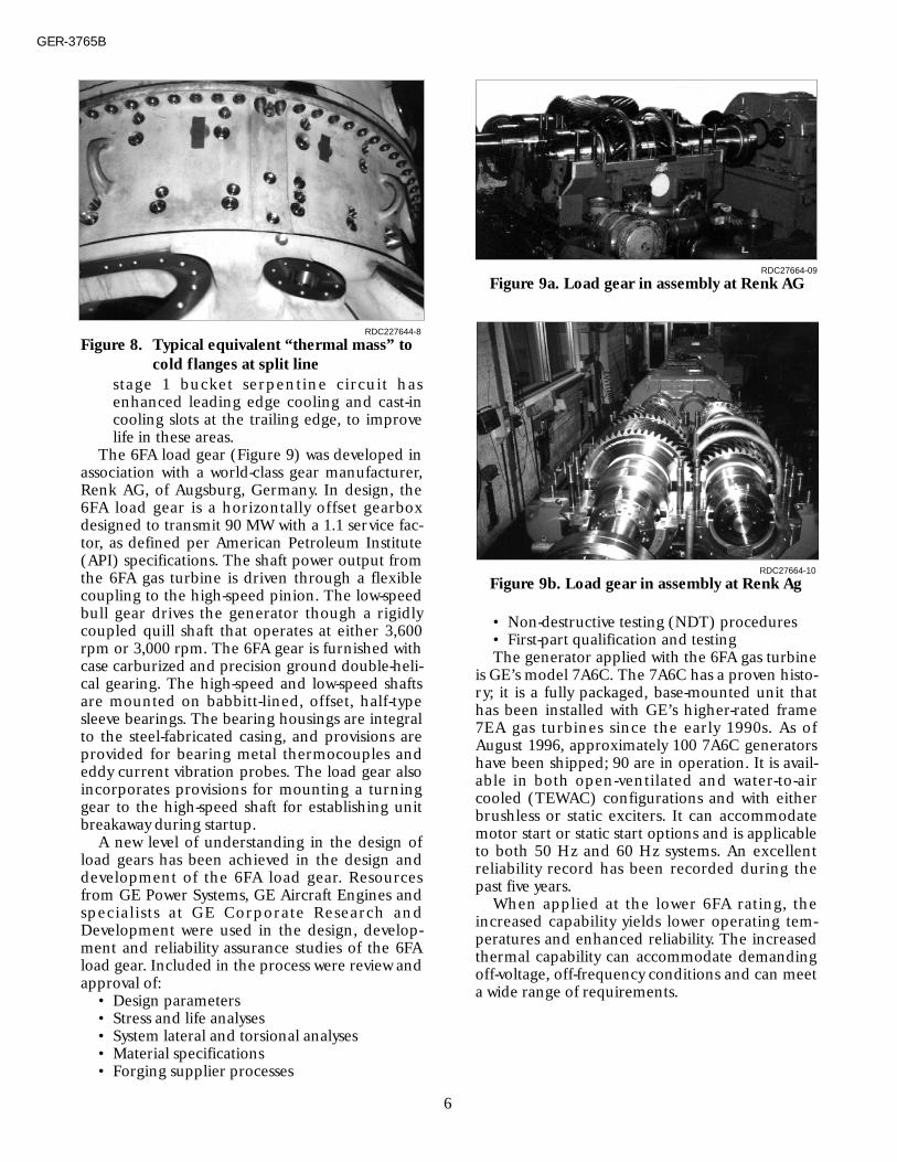
• Tighter compressor blade and bucket tipclearances are also maintained by equivalentthermal masses distributed around theperiphery of the casings (Figure 8), whichprovide compensation for the cold flanges atthe split lines. This provides for rounder cas-ings and tighter tip clearances during opera-tion.
• External casing flanges use an optimizedbolting arrangement for reduced leakage,which has been validated by factory tests.This results in less power required for com-partment cooling and an overall improve-ment in performance.
• Reduced use of cooling air in the hot sectionof the turbine. Judicious use of cooling air forairfoil and shroud cooling in the stage 1 noz-zle, bucket, shroud and stage 2 nozzle haveallowed for more uniform temperature gradi-ents that improve life and performance. The
5
GER-3765B
RDC27664-11
Figure 6. Thermal paint verification test fortransition piece
GT2577
High Pressure Packing Seals
Interstage Diaphragm
Stage 2 & 3 Bucket Tip Seals
GT25770
Figure 7. Honeycomb seal locations
stage 1 bucket serpentine circuit hasenhanced leading edge cooling and cast-incooling slots at the trailing edge, to improvelife in these areas.
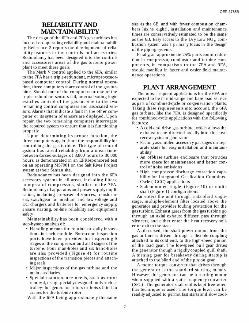
The 6FA load gear (Figure 9) was developed inassociation with a world-class gear manufacturer,Renk AG, of Augsburg, Germany. In design, the6FA load gear is a horizontally offset gearboxdesigned to transmit 90 MW with a 1.1 service fac-tor, as defined per American Petroleum Institute(API) specifications. The shaft power output fromthe 6FA gas turbine is driven through a flexiblecoupling to the high-speed pinion. The low-speedbull gear drives the generator though a rigidlycoupled quill shaft that operates at either 3,600rpm or 3,000 rpm. The 6FA gear is furnished withcase carburized and precision ground double-heli-cal gearing. The high-speed and low-speed shaftsare mounted on babbitt-lined, offset, half-typesleeve bearings. The bearing housings are integralto the steel-fabricated casing, and provisions areprovided for bearing metal thermocouples andeddy current vibration probes. The load gear alsoincorporates provisions for mounting a turninggear to the high-speed shaft for establishing unitbreakaway during startup.
A new level of understanding in the design ofload gears has been achieved in the design anddevelopment of the 6FA load gear. Resourcesfrom GE Power Systems, GE Aircraft Engines andspecialists at GE Corporate Research andDevelopment were used in the design, develop-ment and reliability assurance studies of the 6FAload gear. Included in the process were review andapproval of:
• Design parameters• Stress and life analyses• System lateral and torsional analyses• Material specifications• Forging supplier processes
• Non-destructive testing (NDT) procedures• First-part qualification and testingThe generator applied with the 6FA gas turbine
is GE’s model 7A6C. The 7A6C has a proven histo-ry; it is a fully packaged, base-mounted unit thathas been installed with GE’s higher-rated frame7EA gas turbines since the early 1990s. As ofAugust 1996, approximately 100 7A6C generatorshave been shipped; 90 are in operation. It is avail-able in both open-ventilated and water-to-aircooled (TEWAC) configurations and with eitherbrushless or static exciters. It can accommodatemotor start or static start options and is applicableto both 50 Hz and 60 Hz systems. An excellentreliability record has been recorded during thepast five years.
When applied at the lower 6FA rating, theincreased capability yields lower operating tem-peratures and enhanced reliability. The increasedthermal capability can accommodate demandingoff-voltage, off-frequency conditions and can meeta wide range of requirements.
RDC227644-8
Figure 8. Typical equivalent “thermal mass” tocold flanges at split line
RDC27664-09
Figure 9a. Load gear in assembly at Renk AG
RDC27664-10
Figure 9b. Load gear in assembly at Renk Ag
6
GER-3765B
RELIABILITY ANDMAINTAINABILITY
The design of the 6FA and 7FA gas turbines hasfocused on operating reliability and maintainabili-ty. Reference 2 reports the development of relia-bility features in the controls and accessories.Redundancy has been designed into the controlsand accessories areas of the gas turbine powerplant to meet these goals.
The Mark V control applied to the 6FA, similarto the 7FA has a triple-redundant, microprocessor-based computer control. During normal opera-tion, three computers share control of the gas tur-bine. Should one of the computers or one of thetriple-redundant sensors fail, internal voting logicswitches control of the gas turbine to the tworemaining control computers and associated sen-sors. Alarms that indicate a fault in the other com-puter or its system of sensors are displayed. Uponrepair, the two remaining computers interrogatethe repaired system to ensure that it is functioningproperly.
Upon determining its proper function, thethree computers again share the responsibility forcontrolling the gas turbine. This type of controlsystem has raised reliability from a mean-time-between-forced-outages of 3,800 hours to 30,000hours, as demonstrated in an EPRI-sponsored teston an operating MS7001 on the Salt River Projectsystem at their Santan site.
Redundancy has been designed into the 6FAaccessory systems in all areas, including filters,pumps and compressors, similar to the 7FA.Redundancy of apparatus and power supply dupli-cation, including crossover of sources, transform-ers, switchgear for medium and low voltage andDC chargers and batteries for emergency supply,ensure starting, on-line reliability and equipmentsafety.
Maintainability has been considered with astep-by-step analysis of:
• Handling means for routine or daily inspec-tions in each module. Borescope inspectionports have been provided for inspecting 5stages of the compressor and all 3 stages of theturbine. Four man-holes and six hand-holesare also provided (Figure 4) for routineinspections of the transition pieces and attach-ing seals.
• Major inspections of the gas turbine and themain auxiliaries
• Special maintenance needs, such as rotorremoval, using specially-designed tools such astrolleys for generator rotors or hoists fitted tocranes for the turbine rotor
With the 6FA being approximately the same
size as the 6B, and with fewer combustion cham-bers (six vs. eight), installation and maintenancetimes are conservatively estimated to be the sameas the 6B. Easy access to the Dry Low NOx com-bustion system was a primary focus in the designof the piping systems.
Finally, an approximate 25% parts count reduc-tion in compressor, combustor and turbine com-ponents, in comparison to the 7FA and 9FA,should manifest in faster and easier field mainte-nance operations.
PLANT ARRANGEMENTThe most frequent applications for the 6FA are
expected to be in mid-range and base load serviceas part of combined-cycle or co-generation plants.Taking these requirements into account, the 6FAgas turbine, like the 7FA, is designed specificallyfor combined-cycle applications with the followingfeatures:
• A cold-end drive gas turbine, which allows theexhaust to be directed axially into the heatrecovery steam generator
• Factory-assembled accessory packages on sep-arate skids for easy installation and maintain-ability
• An off-base turbine enclosure that providesmore space for maintenance and better con-trol of noise emissions
• High compressor discharge extraction capa-bility for Integrated Gasification CombinedCycle (IGCC) applications
• Slab-mounted single- (Figure 10) or multi-shaft (Figure 1) configurations
Air enters the unit through a standard single-stage, multiple-element filter located above thegenerator and provides fouling protection for thegas turbine. Exhaust gases from the gas turbine gothrough an axial exhaust diffuser, pass throughsilencers, and either enter the heat recovery boil-er or exit to the stack.
As discussed, the shaft power output from thegas turbine is driven through a flexible couplingattached to its cold end, to the high-speed pinionof the load gear. The low-speed bull gear drivesthe generator though a rigidly coupled quill shaft.A turning gear for breakaway during startup isattached to the blind end of the pinion gear.
A motor torque converter that drives throughthe generator is the standard starting means.However, the generator can be a starting motorwhen supplied with a static frequency converter(SFC). The generator shaft end is kept free whenthis technique is used. The torque level can bereadily adjusted to permit fast starts and slow cool-
7
GER-3765B

down rotation of the gas turbine. A disconnectingcoupling or clutch can also be installed to allowsynchronous condenser operation.
The mechanical accessories are motor drivenand arranged in two modules. One of these mod-ules is used only for liquid fuel operation.Electrical devices, such as auxiliary transformers,switchgears, static frequency converters, are con-tained in the electrical/control module close tothe generator. The modules are fully assembledand factory-tested prior to shipment. The twomechanical accessory modules are located at fixedlocations relative to the gas turbine, which allowsfor quick field installations using prefabricatedpiping.
An array of site-specific designs for these mod-ules provides:
• Aesthetic appearance
• Thermal and acoustic insulation• Heating and ventilation• Fire protection• Redundancy of power supply• Space and means available for maintenanceThese features are established for each plant
according to customer requirements and serviceconsidered (in/out door, new/existing plant,etc.). Additionally, the skid layouts for the varioussystems have generous space to permit easy main-tenance without speciality tools.
The typical general plant arrangement (Figure11) can be adapted to many indoor or outdoorconfigurations. However, the location of the twomain accessory modules must be retained, andthe off-base gas turbine enclosure must be used toachieve 85dBA maximum sound from the unit. Tominimize field installation work, the gas turbine is
8
GER-3765B
GT25758
Figure 10. Slab-mounted single-shaft arrangement
GT25759
Figure 11. Typical general plant arrangement

mounted on a steel base structure with factory-installed piping and electrical components, simi-lar to the 6B. Side-by-side arrangements are partic-ularly suitable for multiple unit plants. Coolingwater needs are secured by external supply (river,sea water with intercooling, etc.) or through fin-
fan coolers. Site civil work can be kept to a mini-mum with grade-level foundations for installationof all modules and pipeways.
STATUSFive units are scheduled to be shipped by the
end of 1996, two of which are to be in commercialoperation by October 1996. Figures 12a through12h show hardware for these units in variousstages of assembly.
Orders as of August 1996 have shown the widerange of both application and customer accep-tance of the 6FA design, in both the 50 Hz and 60Hz markets. The variety of applications covered bythese projects, which include combined-cycle,cogeneration and IGCC, fully demonstrate the
9
GER-3765B
RDC27664-06
Figure 12a. Assembled stage 1 nozzle segments
RDC27664-07
Figure 12b. Stage 1 shroud (background);stage 2 shroud (foreground)
RDC27664-01
Figure 12c. Honeycomb seals on stage 2 and 3diaphragm seals
RDC27664-02
Figure 12d. Stage 3 nozzle segments withdiaphragm seal
RDC27664-04
Figure 12e. Stage 1 nozzle assembly

capabilities of this gas turbine. Combined-cycleapplications include both single-shaft and multi-shaft combined-cycle plant configurations. Figure13 shows the expected fired hours accumulationof these machines over the next three years.
The two launch projects are DestecCogeneration, a natural-gas-only site (Figure 14)in Kingston, Ontario, Canada, and the SierraPacific Power Company’s Piñon Pine PowerProject, a dual-fuel IGCC site located in Reno,Nevada (Figure 15). Both projects’ equipment wasshipped in the first quarter of 1996, with mechani-cal and electrical erection essentially completed inthe second quarter and first firing of the units inAugust. The Destec Cogeneration and the SierraPacific Power Projects are both scheduled to becommercial on natural gas in October 1996, withthe IGCC portion of the Sierra Pacific Projectgoing on-line in December 1996.
Subsequent projects scheduled to go commer-cial in late 1996 or 1997 include a cogenerationfacility in Finland, a single-shaft base load com-
10
GER-3765B
RDC27664-03
Figure 12f. Turbine shellRDC27664-12
Figure 12g. Rotor being installed into unit atGreenville, South Carolina, plant
RDC27644-05
Figure 12h. Unit being assembled atGreenville, South Carolina, plant
0
20
40
60
80
100
120
140
3Q96 1Q97 3Q97 1Q98 3Q98 1Q99
End of Year
60 Hz Applications
50 Hz Applications
- 6FA Fleet (Total)
Ho
urs
(T
ho
usa
nd
s)
GT25766
Figure 13. 6FA operational experience

bined-cycle facility in Italy and a multi-shaft com-bined-cycle facility in the United States.
The no-load tests on these first three units havesuccessfully demonstrated that the design toolsused accurately predicted the operating character-istics of the unit (Table 3). The units exhibitedflawless starting and acceleration to full-speedconditions. Rotor vibration levels for these unitswere well below design criteria and indicated satis-factory stiffness characteristics of the scaled
design. All bolted flanges and shell/casing jointsexhibited no leakage.
CONCLUSIONGE’s design philosophy, based on a firm analyti-
cal foundation and years of experience of gas tur-bine operation, has resulted in reliable, heavy-dutygas turbines. On this basis, successful designs arecarefully scaled to larger or smaller sizes. Scalinghas been used to produce similar designs thatrange from 25 MW to 200 MW. Improved materi-als and components that have been prudently andcarefully applied to increase power and thermalefficiency have resulted in the evolution of provendesigns. Finally, designs are carefully tested anddemonstrated in extensive development facilitiesand by fully instrumented unit tests in order toprovide full confirmation of the design underactual operating conditions.
Using this methodology, the 6FA has beenscaled from the proven 7FA and successfullylaunched into production. Five units are sched-uled to be shipped by the end of 1996, two ofwhich are scheduled to be operational in thesame period. The full-speed no-load tests and ini-tial site startup operations of these first units weresuccessful.
11
GER-3765B
GT25781
Figure 14. Destec CogenerationKingston, Ontario, Canada
RDC27640-6
Figure 15a. Sierra Pacific Power Company’sPiñon Pine Power Project
GT27640-2
Figure 15b. Sierra Pacific Power Company’sPiñon Pine Power Project
Table 36FA TEST RESULTS AT FULL SPEED — NO LOAD
ISO Performance ISO PerformanceExpected (nominal) as Tested
Airflow (lb/s / kg/s) 437 438Compressor pressure ratio 10.68 10.74Compressor efficiency 86.4% 86.2%Turbine efficiency 84.6% 84.9%Turbine inlet temperature (F/C) 1074/579 1083/584Turbine exhaust temperature (F/C) 490/254 495/257

REFERENCES1. Rowen, W.I., “Operating Characteristics of
Heavy-Duty Gas Turbines in Utility Service,”ASME paper No. 88-GT-150, presented at theGas Turbine and Aeroengine Congress,Amsterdam, Netherlands, June 6-9, 1988.
2. “Design of High-Reliability Gas TurbineControls and Accessories,” EPRI Final Report,AP-5823, June 1988.
12
GER-3765B
© 1996 GE Company

LIST OF FIGURES
Figure 1. Typical gas turbine generator arrangementFigure 2. GE F product lineFigure 3. 6FA gas turbineFigure 4. Gas turbine configurationFigure 5. Growth in compressor design evolutionFigure 6. Thermal paint verification test for transition pieceFigure 7. Honeycomb seal locationsFigure 8. Typical equivalent “thermal mass” to cold flanges at split lineFigure 9a. Load gear in assembly at Renk AGFigure 9b. Load gear in assembly at Renk AGFigure 10. Slab-mounted single-shaft arrangementFigure 11. Typical general plant arrangementFigure 12a. Assembled stage 1 nozzle segmentsFigure 12b. Stage 1 shroud (background) and stage 2 shroud (foreground)Figure 12c. Honeycomb seals on stage 2 and 3 diaphragm sealsFigure 12d. Stage 3 nozzle segments with diaphragm sealFigure 12e. Stage 1 nozzle assemblyFigure 12f. Turbine shellFigure 12g. Rotor being installed into unit at Greenville, South Carolina, plantFigure 12h. Unit being assembled at Greenville, South Carolina, plantFigure 13. 6FA operational experienceFigure 14. Destec Cogeneration, Kingston, Ontario, CanadaFigure 15a. Sierra Pacific Power Company’s Piñon Pine Power ProjectFigure 15b. Sierra Pacific Power Company’s Piñon Pine Power Project
LIST OF TABLES
Table 1. Comparison of gas turbine ratings (ISO, Base, 60 Hz)Table 2. 6FA materialsTable 3. 6FA test results at full speed — no load
GER-3765B

Michael C. ConwayMichael Conway has 16 years of power generation experience and is
currently Product Line Manager, F Technology. He graduated fromClarkson University with a BS in engineering.
Jay RamachandranJay Ramachandran is currently Manager, 6FA Engineering Programs.
He has 18 years of design and project management experience at GE’sPower Generation and Aircraft Engine divisions. His engineering experi-ence is primarily in the design of turbine high-temperature compo-nents. He also has significant experience gas turbine system design fromhis contribution to GE’s advanced H-generation machines.
Jay graduated from the University of Cincinnati with an MS in engi-neering. He is also a graduate of GE’s ABC gas turbine engineering pro-gram. He holds two patents on his work in gas turbine engineering atGE.
A list of figures and tables appears at the end of this paper