geotextile tubes in environmental applications ... · pdf filegeotextile tubes in...
TRANSCRIPT
Geotextile Tubes in Environmental Applications Martin Smith (B.E. Civil) Business Development Manager, Global Synthetics Pty Ltd, 8/28 Oramzi Road, Girraween, NSW 2145, Australia, Telephone: +61296310744, Telefax: +61296310755, E-mail: [email protected] Business Development Manager Global Synthetics Qld Pty Ltd, 44 Telford Street, Virginia, QLD 4014, Australia, Telephone: +61738657000 Telefax: +61738654444. ABSTRACT: Geotextile tubes have been successfully used to dewater contaminated sediments, industrial process waste, agricultural process waste, sewerage sludge and other such waste stream products. The system provides a low cost, efficient means of containment and consolidation of waste. The technology is evolving with new developments in fabric construction and fabrication techniques. This paper reviews the historical development of geotextile containment products and the wider applications of use and then specifically discusses the installation and field performance of geotextile tubes used for dewatering waste in a sewage treatment plant (STP). The critical design parameters are discussed and related to the overall performance of the system at Winmalee STP. Geotextile containment and dewatering technology is versatile and lends itself to a wide field of engineering applications. KEYWORDS: Geotextile Tube, Geotextile Container, Geotextile Dewatering Tube, Geotextile Bags, Dewatering. 1 INTRODUCTION
The use of geotextile manufactured into a containment product has been used for many years in a wide variety of applications. The use of sand filled bags, “sandbags” have been used the world over to form simple and effective retaining structures in land stabilisation retaining structures or to provide a temporary barrier against floodwaters. More recently, there have been developments that have justified the use of larger bags to be effective in providing more permanent solutions in coastal structures for defence against coastal erosion problems. Generally in these applications of coastal or marine works the geotextile products used, are defined by the geometrical shape and size of the product formed. Containment products can be broadly described as: Geotextile tubes or Geotextile containers or Geotextile bags In recent years there has been an increasing acceptance in the use of such products in environmental applications. This paper looks at some historical perspectives of this technology with a more detailed review in the specific use of environmental management of waste and the benefits that can be available with the use of such products. A case study is presented that reviews the application of using permeable geotextile tubes, as a low cost dewatering option, in a municipal sewage treatment plant 2 CONTAIMENT TYPES DESCRIBED 2.1 Geotextile Tubes Geotextile textile tubes are factory fabricated into closed end cylinders, with one or more designed filling ports located on the top of the cylinder, such that material may be pumped or hydraulically placed into the geotextile tube. In coastal works this will normally be readily available beach sand or similar non cohesive fine grained material. The use of such materials ensures the finished structure is not subject to the effects of longer term” consolidation” and subsequent shape change upon completion of fill options. Shape change in such structures may seriously affect the integrity of the product and have a consequential major influence on specific design intent. Such an example may be to achieve a required geotextile tube height to retain proposed fill materials. The tubes are constructed from either a woven or nonwoven geotextile that has been designed with ultimate tensile strengths typically in the range of 60-120kN/m. Ultimate geotextile strains of candidate geotextile types, at ultimate tensile strength, will vary from a maximum of approximately 15% for high strength woven geotextiles to some 50% for nonwoven geotextiles. The influence of strain should be a consideration in the design and application of containment structures. Generally the selected geotextile has been designed such that the pore size (EOS), is typically around 400 microns or smaller and the fabric will typically have similar tensile strengths in both the fabric roll length (warp) and

cross roll width (weft). Geotextile tubes are manufactured with a “theoretical diameter” between 1 to 10m. The length of such tubes may be up to 100m although more typically 20-30m. The tubes are delivered to site and hydraulically filled insitu, either on land or in water. Significant stresses are imposed on such products during filling operations. Geotextile tubes are used in coastal defence works (generally as a back beach protection structure), river training structures, and groynes and more recently, in environmental applications of dewatering. Exposed geotextile tubes that are placed in a public domain (such as a beach) may be a source of vandal attack and where possible, the geotextile tube should be buried, when warranted. Tubes that are used for dewatering applications are generally used in secure environments and are not subject to such issues. Figure 1 Typical Geotextile Tube Photo 3 Geotextile with Scour Apron Photo 1 Geotextile Back Beach Protection. 2.1 Geotextile Containers Geotextile containers are purpose designed, large volume containers, which are either open top or may more closely resemble a conventional geotextile tube. The important feature of such products is that the method of delivery of geotextile containers once filled is from a split bottom barge. The geotextile containers are constructed from either a high strength woven or nonwoven geotextile and are specifically sized to suit the split bottom barge that will be engaged to deploy the container. The selection of fabric type may well be dictated by the proposed geotextile container size and application. Appropriate woven geotextiles can be manufactured with much higher strengths than nonwoven geotextiles. Typically the strength of woven geotextiles may be manufactured to 600kN/m or higher whilst nonwoven geotextiles are normally strength limited to approximately 70kN/m. In smaller geotextile container sizes nonwoven geotextile may be a preferred choice, as this type of fabric offers greater elongation characteristics than woven geotextiles and may offer improved resistance against sand abrasion in active surf zones. Large volume containers will require the strengths associated with suitable woven geotextiles. The geotextile containers are either mechanically or hydraulically filled, within the container, in place, within the barge. The filling point may be either close to a proposed dump location or may be some distance from such location, dictated by a suitable source of fill material. Geotextile containers may typically have volume capacities of between 100-700 m3. Geotextile containers will typically be of lengths up to about 25m and the width of a typical split bottom barge. Containers should not be overfilled such that the geotextile container can allow fill redistribution within the

Photo 4 Geotextile Container Photo 5 Geotextile Container in Barge closed container prior to emptying through the barge bottom. Requirements for fill volume will vary somewhat dependent upon container volumes and subsequent geotextile fabric selection used in the construction of such containers. Geotextile containers may be useful in the construction of marine structures that would otherwise have been very expensive or impractical to construct. Structures that have been constructed around the world include artificial surfing reefs, bund wall structures that have allowed later hydraulic fill to be placed to reclaim land and environmental containment at deep sea depth of waste materials. Geotextile containers require a good appreciation of the extreme fabric forces that are generated during deployment. Both within fabric forces and seam strengths need to be of very high standard such that the geotextile container maintains total integrity during deployment and at sea floor impact. In some applications, high quality seaming techniques as well as rope closure of the geotextile container is required to withstand such forces, prior to dropping through the bottom of the barge. 2.2 Geotextile Bags Geotextile bags are a simple device using either nonwoven or woven fabrics that are factory seamed with one end left open for field closure, after completion of geotextile bag filling operations. The size of geotextile bags is generally in the range of 0.05m3 to approximately 5m3. The shape of the bag may be pillow shaped, box shaped or mattress shaped dependent upon the final application of use. Geotextile bags are finding a very useful application in beach protection works where an immediate, readily installed treatment is required for erosion problems. Of course like all structures that act as a retaining structure, very careful analysis should be made with respect to overall stability and in particular, specific scour issues that will need to be addressed in such dynamic environments. Similarly the use of suitable fabrics of sufficient tensile strength together with good factory and field seaming (for final closure) of the geotextile bags is required for successful implementation of structures using the bags. Photo 6 Geotextile Bag Placement. Photo 7 Filling Geotextile Bag

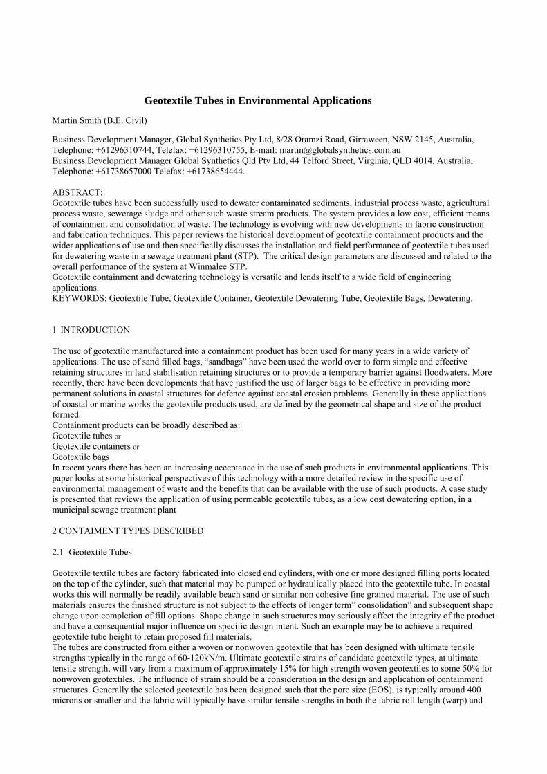
3 FUNDAMENTAL CHARACTERISTICS OF CONTAINMENT PRODUCTS 3.1 Geotextile Tube Characteristics Geotextile tubes have been briefly described earlier. The characteristics are that the fabric construction allows water to pass freely through the pores of the fabric in a relatively controlled manner whilst retaining solids. The fabric is sufficiently strong to allow the development of large fabric forces that arise as a result of filling operations. Additionally superior seaming techniques should ensure that failure does not occur at weak seam locations. Geotextile tubes are factory fabricated and formed by seaming adjacent lengths of fabric together in either a tangential or circumferential direction (relative to geotextile tube length) such that a cylinder is made. Appropriate seaming completes the process at the geotextile tube ends to make a closed system. Dependent upon tube lengths, a number of filling ports are positioned along the length of the tube. Fill port spacing is somewhat dependent upon the intended application. Geotextile tubes used in permanent marine or hydraulic structure applications will generally require a greater number of fill ports than geotextile tubes used in environmental dewatering applications. This requirement is just a function of the material being delivered to fill the tube. For marine and hydraulic works and where the fill material is sand, there is a tendency for the sand being delivered to “block” within the geotextile tube. Subsequently, there may be a need to allow fill placement to continue along the length of the geotextile tube by inserting the delivery nozzle in a close spaced, alternate fill port location. It is important to note that when pumping sand into a geotextile tube, very large volumes of water are required to successfully complete the filling operations. Typically the ratio of water to sand may be 20:1. In such structures there may be a need to ensure that water introduced into the system, does not cause geotextile tube scour issues, as it exits the site. Some preventative method such as placing a plastic sheet to prevent such problems at the base of the tube may be required. When the delivery involves highly liquid sludge material, such as will be involved in many geotextile tube dewatering applications, there is a much lower likelihood of “blockage” and generally a requirement for fewer fill ports. Scour issues in dewatering applications is not an issue as geotextile tube discharge rates are much reduced. Geotextile tubes are generally characterised in terms of their theoretical diameter DT or more commonly in terms of the circumference CT of the geotextile tube. Geotextile tubes have had a significant promotional effort in the USA and it is in this market that tubes are more frequently referred to in terms of the circumference. Tubes typically are fabricated with a circumference between 4.5m to 27m and with lengths to 100m. The length of the chosen tube is either within some increment of the fabric roll length used or may be such that the full roll length of the fabric is used. Structures that require longer lengths of geotextile tube are just end tube stacked to achieve such field lengths. The basic concept of theoretical tube dimensions is shown in Figure 2. Tubes when filled will resemble a profile as shown in Figure 3. Figure 2 Figure 3 3.1.1 Geotextile Tube Stresses When filling geotextile tubes a combination of stresses (tensions) are imparted on the fabric. Simplistically the tensions can be considered at three locations of the tube (refer Figure 4). These are the tensions developed around the circumference of the geotextile tube Tc, along the axial length of the geotextile tube Ta, and the connection of any fill port with the geotextile tube Tp. Tensions developed in geotextile tubes, when used in permanent coastal, marine or hydraulic applications should use an analysis based on shear resistant fills as being appropriate. In environmental applications where the fill material is likely to be a liquid, the analysis of the geotextile tube tensions should consider the fill with zero shear resistance.
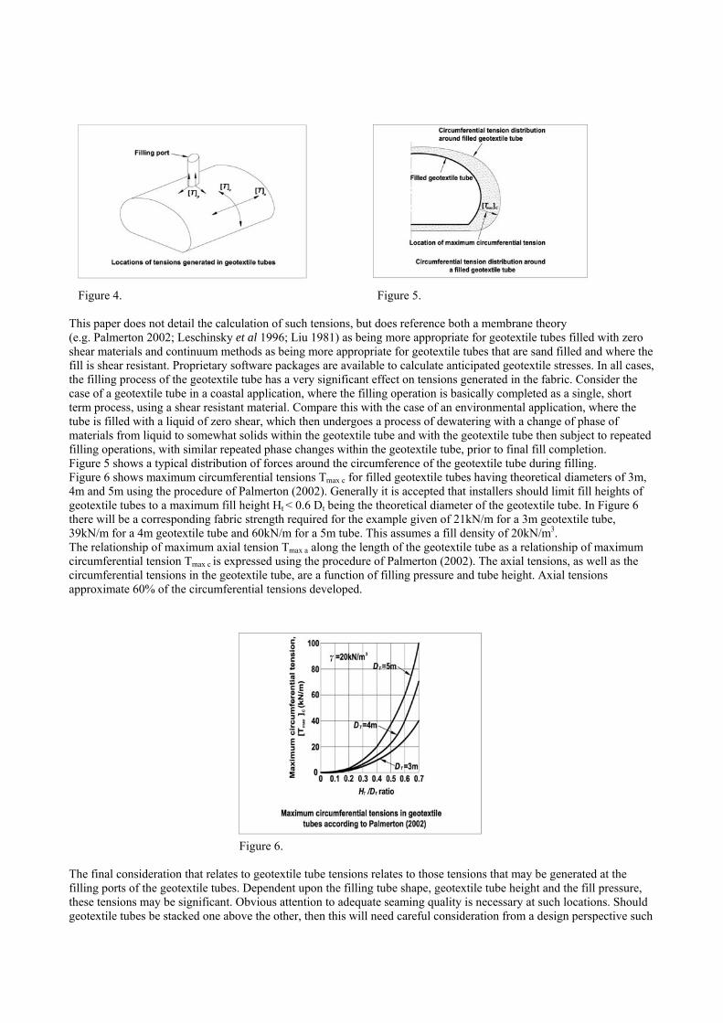
Figure 4. Figure 5. This paper does not detail the calculation of such tensions, but does reference both a membrane theory (e.g. Palmerton 2002; Leschinsky et al 1996; Liu 1981) as being more appropriate for geotextile tubes filled with zero shear materials and continuum methods as being more appropriate for geotextile tubes that are sand filled and where the fill is shear resistant. Proprietary software packages are available to calculate anticipated geotextile stresses. In all cases, the filling process of the geotextile tube has a very significant effect on tensions generated in the fabric. Consider the case of a geotextile tube in a coastal application, where the filling operation is basically completed as a single, short term process, using a shear resistant material. Compare this with the case of an environmental application, where the tube is filled with a liquid of zero shear, which then undergoes a process of dewatering with a change of phase of materials from liquid to somewhat solids within the geotextile tube and with the geotextile tube then subject to repeated filling operations, with similar repeated phase changes within the geotextile tube, prior to final fill completion. Figure 5 shows a typical distribution of forces around the circumference of the geotextile tube during filling. Figure 6 shows maximum circumferential tensions Tmax c for filled geotextile tubes having theoretical diameters of 3m, 4m and 5m using the procedure of Palmerton (2002). Generally it is accepted that installers should limit fill heights of geotextile tubes to a maximum fill height Ht < 0.6 Dt being the theoretical diameter of the geotextile tube. In Figure 6 there will be a corresponding fabric strength required for the example given of 21kN/m for a 3m geotextile tube, 39kN/m for a 4m geotextile tube and 60kN/m for a 5m tube. This assumes a fill density of 20kN/m3. The relationship of maximum axial tension Tmax a along the length of the geotextile tube as a relationship of maximum circumferential tension Tmax c is expressed using the procedure of Palmerton (2002). The axial tensions, as well as the circumferential tensions in the geotextile tube, are a function of filling pressure and tube height. Axial tensions approximate 60% of the circumferential tensions developed.
Figure 6. The final consideration that relates to geotextile tube tensions relates to those tensions that may be generated at the filling ports of the geotextile tubes. Dependent upon the filling tube shape, geotextile tube height and the fill pressure, these tensions may be significant. Obvious attention to adequate seaming quality is necessary at such locations. Should geotextile tubes be stacked one above the other, then this will need careful consideration from a design perspective such
that the imposed loads are adequately considered and that the final geotextile tube arrangement will act as an intended, coherent structure. 3.1.2 Factors of Safety The geotextile fabric used in the construction of the geotextile tube and all components associated in the construction of the geotextile tube, including any necessary seaming & geotextile tube fill ports must have adequate tension capacity both during filling operations and during the service life of the geotextile tube. Simply put the required ultimate tensile strength of the geotextile should be Tuc or Tua ≥ FS (Tmax c or T max a or Tmax s) where Tuc and Tua are the ultimate tensile capacities of the fabric used in either the circumferential or axial direction of the geotextile tube. Tmax c or T max a are the calculated axial or circumferential tensile stresses for a given tube condition. Tmax s is the seam strengths adopted. Such seam strengths are determined from laboratory testing. FS is the global factor of safety adopted. Generally in the absence of specific calculations a default value for FS of 4 to 5 is adopted. Specific considerations that have not been discussed might be the likelihood of ultra-violet degradation for the case of a geotextile tube exposed for long periods in sunlight. This will obviously require careful assessment of appropriate increased factors of safety or other protective measures for the fabric, to minimise fabric strength losses. 3.2 Geotextile Containers 3.2.1 Geotextile Container Characteristics Geotextile containers are large volume geotextile containers that are specifically fabricated to be deployed through the bottom of a split bottom barge. Typically such geotextile containers may vary in volume from 100m3 to 700m3.The geotextile container is fabricated for specific split bottom barges that are available in the local area and hence, there may be limitations on the size of the geotextile containers to be deployed, based on availability of such barges. The geotextile containers may be constructed from either a woven or nonwoven geotextile. The method of fabrication may be either a closed system geotextile container that looks somewhat like a geotextile tube or may be an open top system whereby closure of the geotextile container is finalised, on the barge, after filling is completed. In all cases the fabric used must be sufficiently strong to resist deployment forces generated. The fabric should be designed such that the filtration characteristics of the fabric used, limits long term loss of material from within the geotextile container and that the fabric is sufficiently robust to prevent long term abrasion issues that may be associated with placement in a hydraulically active, sand charged environment, such as a coastal protection structure. Geotextile containers may be used to create a range of underwater structures. Works that have been completed or could be considered include artificial surfing reefs, offshore breakwaters, slope buttressing or containment dykes. It is the authors understanding that some work has been carried out in Japan on containment of contaminants within geotextile containers and dumping in the sea at depth. Placement of geotextile containers can be somewhat problematic. Positioning techniques should include GPS positioning devices to locate the barge over the drop zone. When precise geotextile container shapes are required such as may be required in a surfing reef it is difficult for such shapes to be formed and the expectation of the designer should be tempered by the realities of placement. Shapes may require multiple geotextile container drops with very small increments in change of geotextile container location. Additionally where a stable structure is to be formed consideration should be given to adequate scour protection measures such that the structure retains the installed and design shape integrity. Stability of the structure both from internal and external considerations should be considered. Checks if necessary should be made for sliding, bearing, settlement, global and overturning stability. Typically it is the writer’s belief that large volume geotextile containers require fabrics with high ultimate tensile capacity of at least 200kN/m and may indeed be greater for extreme applications of use. 3.2.2 Geotextile Container Stresses Some research has been carried out to attempt to quantify the stresses employed during deployment. Such research is very much in the infancy of development.

Schematically the source of tensions generated during geotextile container installation is presented at Figure 7 (After Lawson; 2008). Figure 7. During exit of the geotextile container from the barge, tensions in the fabric are determined by the speed of barge bottom opening, by the size of barge opening relative to the width of the geotextile tube to be deployed, the condition of the surface of the barge bottom and the ability of the geotextile container to exit the barge freely (slip sheets may be required). Geotextile container fabric tensions are additionally influenced by the type of material that is contained within the geotextile container and the fact that some necking at the bottom of the split barge occurs due to the barge geometry. This geometry can cause the geotextile container to be deployed within the middle section of the barge followed a little later by the geotextile container at the barge ends. The container may exit the barge in a “banana” shape. On exit, the geotextile container will soon approach terminal velocity dependent upon proposed deployment depths. The depth, at which a terminal velocity is achieved, has been estimated at 10m-15m. Terminal velocity is normally 5-8m/s (Lawson 2008). Obviously there are tensions generated in the fabric due to redistribution of forces within the geotextile during free-fall. At point of impact, the tensions generated are a combination of size of geotextile container, velocity at impact (this being a function of depth) and the inclination of the geotextile container at point of impact. A geotextile container that can be dropped with a point of impact that is parallel to the seabed will be preferable and with lower fabric tensions than that of a geotextile container that is dropped with some point loading effects. Contributing to fabric tensions will be the condition of the seabed and the type of material contained within the geotextile container. Geotextile containers that contain shear resistant materials such as sand are likely to generate lower fabric tensions than those geotextile containers that contain low shear resistance materials such as estuarine muds and other such fluid materials. 3.3 Geotextile Bags 3.3.1 Geotextile Bag Characteristics Geotextile bags are unique from the other geotextile containment products mentioned in this paper. They can be made in a wide variety of shapes and sizes and that they can be placed precisely to form a structure. Generally the geotextile bag is dry land filled, sewn closed at the bag top and then transported to the near site location and carefully placed within the structure at reasonably precise locations. The geotextile bag is generally filled with a shear resistant material such as sand and careful attention should be made to fully fill the geotextile bag. Obviously the bags should be made as dense as possible with contained fill and it may be useful to introduce water into the process such that the sand can be hydraulically filled. Geotextile bags are generally constructed from nonwoven geotextile with high quality seaming at all edges to ensure geotextile bag integrity. The mass of the nonwoven geotextile used is generally in the range of 600g/m2 to 1200g/m2 . Such a fabric mass will provide the required tensile capacity as well as the environmental and hydraulic performance requirements. Sometimes even heavier mass fabric may be used when required in extreme applications of use. It is proposed that a staple fibre nonwoven geotextile will perform better in terms of long term abrasion for this application

than other types of geotextiles available. Abrasion can be associated with structures that are subject to dynamic loadings of wave attack combined with water borne sand particles. As with geotextile tubes used in coastal applications in exposed environments the possibility of vandal attack should be considered. Some manufacturers promote the use of geotextile tubes and geotextile bags with an additional coating process that is reported to be vandal deterrent. Geotextile bags can be rapidly deployed to provide short term or long term protection to assets in situations of coastal erosion or flooding. Handling of bags can be accomplished by the use of special handling clamps or other suitable means that protects the bags from mechanical handling damage. Geotextile bags may be used in applications of slope buttressing, groynes, protection dykes and similar such structures. 3.3.1 Geotextile Bag Design Geotextile bags must be designed sufficiently strong to prevent rupture. Both factory and field seaming techniques should be verified such that at least 60% of the fabric ultimate tensile strength can be achieved in seam strengths, when tested with an appropriate wide width tensile test. When using narrow width seam index tests such as a grab tensile test, this relationship may be 80%. Geotextile bags are designed as mass gravity structures with appropriate design of toe scour protection, if necessary. Internal checks relating to sliding (bag/bag) should be assessed. The fabric pore size shall be such that long term migration of fines is avoided from the geotextile bag. Flow regimes in applications using these products are generally dynamic and particular attention should be payed to the potential of fill loss. Liquefaction of the sand fill contained within the bag may cause movement of sand within the geotextile bag and cause loss of shape and subsequent loss of stability within the structure that is formed. Sand bags have some advantage over other geotextile containment methods, in that, if there is local damage to a single bag(s), the replacement operation is a reasonably simple process. 4.0 GEOTEXTILE TUBE DEWATERING 4.1 General Dependent upon the imagination of the designer or user, geotextile containment products as discussed may be used to solve some application of civil, coastal or environmental engineering. A specific use of one such product, the geotextile tube, is discussed in applications of dewatering waste. The geotextile tube is not presented as a panacea for all solutions of dewatering waste but is offered as one possible solution that may offer environmental and economic benefits for some applications. The idea of capturing very liquid wastes and processing into a more manageable product that can be either transported to waste in a more economic manner or with the waste reused as a by-product is very attractive in today’s environmentally aware culture. Geotextile tubes have been used successfully in a wide variety of industries that include agricultural waste, industrial waste, mining waste, municipal waste treatment and food waste processes. The geotextile tube process is a combination of geotextile fabric, suitable drainage systems to collect the liquid from the geotextile tube, suitable impoundment measures to capture the liquid dewatered and delivery methods to either discharge liquids to watercourses (if the process is clean enough) or return to on-site storage facilities, for reuse or possible further treatment processes. Additionally there may be a need for dose meters to introduce suitable dewatering accelerants (polymers) into the waste stream prior to the geotextile tube dewatering process. Suitable disposal methods of the dewatered waste must be considered. Figure 8 represents such an arrangement.
Figure 8
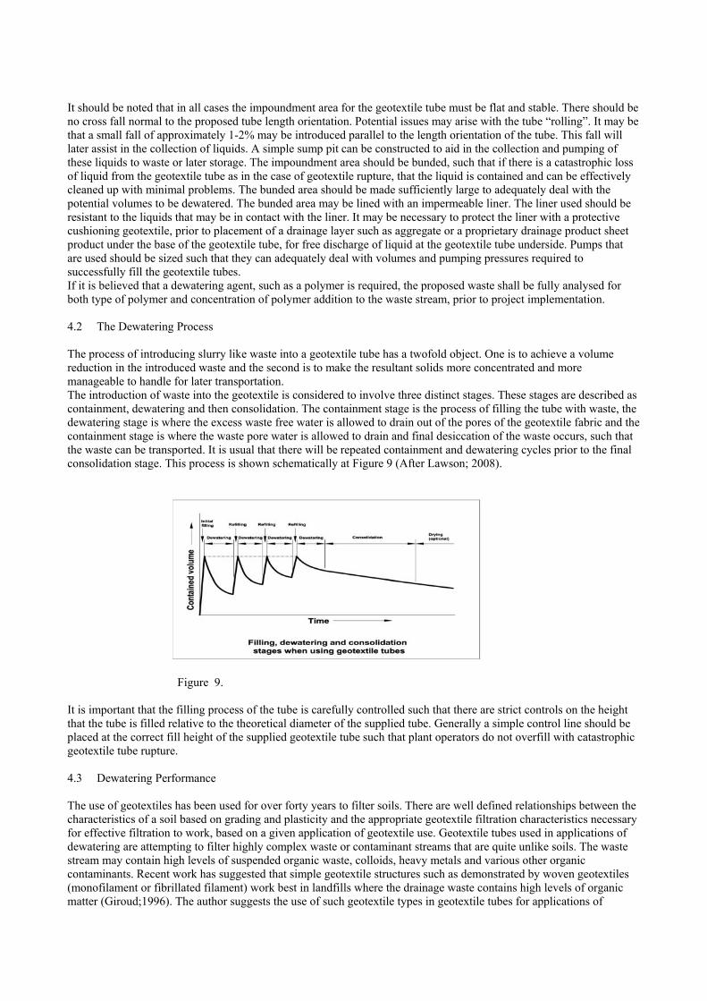
It should be noted that in all cases the impoundment area for the geotextile tube must be flat and stable. There should be no cross fall normal to the proposed tube length orientation. Potential issues may arise with the tube “rolling”. It may be that a small fall of approximately 1-2% may be introduced parallel to the length orientation of the tube. This fall will later assist in the collection of liquids. A simple sump pit can be constructed to aid in the collection and pumping of these liquids to waste or later storage. The impoundment area should be bunded, such that if there is a catastrophic loss of liquid from the geotextile tube as in the case of geotextile rupture, that the liquid is contained and can be effectively cleaned up with minimal problems. The bunded area should be made sufficiently large to adequately deal with the potential volumes to be dewatered. The bunded area may be lined with an impermeable liner. The liner used should be resistant to the liquids that may be in contact with the liner. It may be necessary to protect the liner with a protective cushioning geotextile, prior to placement of a drainage layer such as aggregate or a proprietary drainage product sheet product under the base of the geotextile tube, for free discharge of liquid at the geotextile tube underside. Pumps that are used should be sized such that they can adequately deal with volumes and pumping pressures required to successfully fill the geotextile tubes. If it is believed that a dewatering agent, such as a polymer is required, the proposed waste shall be fully analysed for both type of polymer and concentration of polymer addition to the waste stream, prior to project implementation. 4.2 The Dewatering Process The process of introducing slurry like waste into a geotextile tube has a twofold object. One is to achieve a volume reduction in the introduced waste and the second is to make the resultant solids more concentrated and more manageable to handle for later transportation. The introduction of waste into the geotextile is considered to involve three distinct stages. These stages are described as containment, dewatering and then consolidation. The containment stage is the process of filling the tube with waste, the dewatering stage is where the excess waste free water is allowed to drain out of the pores of the geotextile fabric and the containment stage is where the waste pore water is allowed to drain and final desiccation of the waste occurs, such that the waste can be transported. It is usual that there will be repeated containment and dewatering cycles prior to the final consolidation stage. This process is shown schematically at Figure 9 (After Lawson; 2008). Figure 9. It is important that the filling process of the tube is carefully controlled such that there are strict controls on the height that the tube is filled relative to the theoretical diameter of the supplied tube. Generally a simple control line should be placed at the correct fill height of the supplied geotextile tube such that plant operators do not overfill with catastrophic geotextile tube rupture. 4.3 Dewatering Performance The use of geotextiles has been used for over forty years to filter soils. There are well defined relationships between the characteristics of a soil based on grading and plasticity and the appropriate geotextile filtration characteristics necessary for effective filtration to work, based on a given application of geotextile use. Geotextile tubes used in applications of dewatering are attempting to filter highly complex waste or contaminant streams that are quite unlike soils. The waste stream may contain high levels of suspended organic waste, colloids, heavy metals and various other organic contaminants. Recent work has suggested that simple geotextile structures such as demonstrated by woven geotextiles (monofilament or fibrillated filament) work best in landfills where the drainage waste contains high levels of organic matter (Giroud;1996). The author suggests the use of such geotextile types in geotextile tubes for applications of

dewatering. Obviously the fabric strength should be sufficient to withstand the tensile stresses generated during filling operations. The analysis of tensile forces generated within the geotextile tube is particularly complex, particularly during the most onerous conditions of subsequent filling operations with a tube that has already started some consolidation processes. Tubes that are left for extended periods of time then attempted to refill are more likely to suffer fabric or seam failure. The performance of the geotextile tube should be assessed on the efficiency of achieving volume reductions, that there should not be significant loss of waste through the geotextile tube walls with time and that there should not be a reduction in effluent quality from the geotextile tube with time. Dewatering of the geotextile tube is a highly complex interaction between the waste introduced and the hydraulic conductivity of the waste during the dewatering stage as well as the filtration characteristics of the geotextile tube used. Some wastes will naturally dewater quite easily but generally there is a recommendation made by the author that the use of dewatering accelerants are required in most cases to maintain reasonable dewatered volumes consistent with volumes of waste to be treated. A general overview of dewatering accelerants follows. 4.4 Dewatering Accelerants Chemicals have been used to separate suspended solids, colloids and organic matter from water in many applications. The use of suitable chemical additives within the geotextile tube is generally a positive in terms of increasing the rate of dewatering within the geotextile tube. Generally polymers will either coagulate fine particle (which are often charged) into larger stable particles or will flocculate particles into larger masses. Sometimes a combination of coagulation and flocculation is required. The proper use of polymers can control the filter cake permeability on the inside geotextile tube face surface which will achieve the successful balance of effluent quality and dewatering rate. Water soluble organic polymers are highly effective dewatering accelerants. These polymers generally have an ion exchange site which gives the molecule an ionic charge. Those polymers with a positive charge are called cationic and those with a negative charge are called anionic. Some molecules are neutrally charged. The type of accelerant used and the quantity of accelerant used are critical to the success of such polymers. Cationic polymers usually work best in environments of elevated pH whilst anionic polymers work better in environments of lower pH. The selection of the appropriate polymer and dosage rate can be determined from simple laboratory bench trials. It may be necessary, dependent upon the magnitude of the dewatering project being undertaken, to carry out larger scale, field trials. Generally, suppliers of such polymer product will assist in selection trials. In some situations, the appropriate dosage meters for the correct addition of polymers into the waste stream, may be hired from polymer suppliers. Any decision to use polymers will be economically driven both in terms of the polymer costs and the economic benefits to the project associated with the use of polymers and the increased dewatering rates achieved. Of significant benefit, is that when polymers are used, certain metals can be precipitated from solution. Metals such as lead, zinc, cadmium, mercury and arsenic as well as non soluble organic compounds such as PCBs, PAHs, pesticides and dioxins may be successfully contained within the geotextile tube. Figure 10 shows graphically the effect of chemical accelerants on geotextile tube dewatering for waste streams that accept polymer additions.
Figure 10 Figure 11

Figure 11 shows the negligible effect of polymer addition on a particulate material such as fly ash that has minimal suspended solids or organic matter. Obviously the addition of polymers on some waste streams is not warranted. 4.5 Dewatering Geotextile Tube Stresses We have reviewed the stresses in a geotextile tube. It can be shown that for geotextile tubes (Palmerton 2002) the circumferential tensions generated in a geotextile tube, with an assumed sludge density of 11kN/m3, significantly increase, when the ratio HT ratio becomes larger than 0.4DT. Reference is made to Figure 12. The requirement for this limitation becomes more apparent as the theoretical geotextile tube diameter increases. Figure 12 The axial tensions generated in geotextile tubes are approximately 60% of the maximum geotextile tube circumferential tensions. As noted previously, particular attention should be made to fill port seams as local stress concentrations may occur at such locations. At Table 1 are the recommended maximum fill heights of geotextile tubes used in applications of dewatering (ProTube® Product Brochure Global Synthetics, 2008).
Theoretical Geotextile Tube Circumference
(m)
Theoretical Geotextile Tube Diameter (m)
Recommended Maximum Geotextile Tube Fill Height
(m) 4.5 1.45 0.8
6.8 2.2 1.2
9 2.9 1.4
11.3 3.6 1.5
13.5 4.4 1.6
18 5.8 1.8
27 8.7 1.9
Table 1- Relationship for Maximum Fill Heights to Theoretical Tube Diameters As the theoretical geotextile tube diameter increases, the ratio of maximum geotextile tube fill heights, expressed as a percentage of the theoretical geotextile tube diameter, approaches values closer to 20% for the largest tube. As the size of the geotextile tube increases, so must the care taken to adhere to recommended fill heights. In certain situations of environmental dewatering it may be necessary to stack tubes one on top of the other. This will generally be for reasons of space limitations. There will be some enhanced dewatering effects of such an arrangement; however there will be additional stresses imposed upon underlying geotextile tubes that need to be considered. Such a scenario is shown at Figure 13.

Figure 13 5 CASE STUDY – WINMALEE SEWAGE TREATMENT PLANT Winmalee Sewage Treatment Plant is a waste water treatment facility located on the western outskirts of Sydney, NSW, Australia. The plant is operated by Sydney Water, with the plant servicing the population encompassing the lower Blue Mountains. The plant is located in an environmentally sensitive area and is located on an escarpment, near the town of Winmalee, NSW. Site conditions are very constrained with limited space and difficult terrain. Sydney Water proposed some extensive modifications within their secondary biosludge reactor basin with additional pump capacity and pipe upgrades required. Prior to such works being undertaken the reactor basin needed to be emptied and sludge removed and transported to disposal. The reactor basin has a filled volume capacity of some 8000m3. The waste stream is an aerobic digested sludge. It was estimated that the average solids content was 8% throughout the basin with solids content higher at the bottom of the basin becoming less solid towards the surface. A-TEK Environmental Pty Ltd, a specialist contractor in waste management, was engaged to provide a suitably economic solution to the problems presented by the site location, terrain conditions and environmental restraints. The chosen solution involved the use of ProTube® geotextile dewatering tubes, vacuum truck technology, small amphibious dredging methods and the use of dewatering accelerants. Two geotextile dewatering tubes were involved in this section of works with a third tube used on the Winmalee site for a different area of work. The tubes supplied were each 13.5 m theoretical circumference and 20m in length. Each geotextile tube has a calculated volume capacity of some 200m3 based on the recommended fill heights for the size of geotextile tube. The geotextile fabric used in the construction of the geotextile tubes was a high strength, high flow woven geotextile. Typically the product has tensile strengths of 105kN/m in the geotextile tube length direction and 70kN/m in the axial or width direction of the geotextile tube. All geotextile tubes were constructed with necessary seams running in the direction of geotextile tube length. Two fill ports were installed in each tube.
Photo 8 Positioning the geotextile tube. Photo 9 Filling of geotextile tube commences
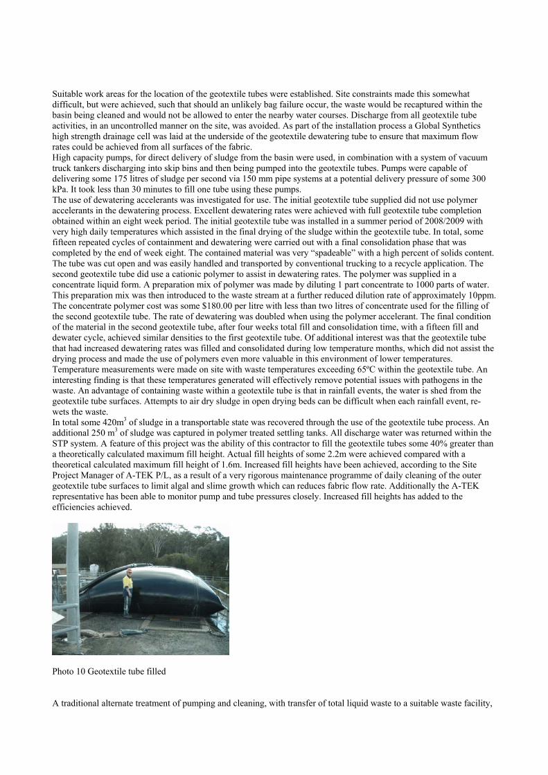
Suitable work areas for the location of the geotextile tubes were established. Site constraints made this somewhat difficult, but were achieved, such that should an unlikely bag failure occur, the waste would be recaptured within the basin being cleaned and would not be allowed to enter the nearby water courses. Discharge from all geotextile tube activities, in an uncontrolled manner on the site, was avoided. As part of the installation process a Global Synthetics high strength drainage cell was laid at the underside of the geotextile dewatering tube to ensure that maximum flow rates could be achieved from all surfaces of the fabric. High capacity pumps, for direct delivery of sludge from the basin were used, in combination with a system of vacuum truck tankers discharging into skip bins and then being pumped into the geotextile tubes. Pumps were capable of delivering some 175 litres of sludge per second via 150 mm pipe systems at a potential delivery pressure of some 300 kPa. It took less than 30 minutes to fill one tube using these pumps. The use of dewatering accelerants was investigated for use. The initial geotextile tube supplied did not use polymer accelerants in the dewatering process. Excellent dewatering rates were achieved with full geotextile tube completion obtained within an eight week period. The initial geotextile tube was installed in a summer period of 2008/2009 with very high daily temperatures which assisted in the final drying of the sludge within the geotextile tube. In total, some fifteen repeated cycles of containment and dewatering were carried out with a final consolidation phase that was completed by the end of week eight. The contained material was very “spadeable” with a high percent of solids content. The tube was cut open and was easily handled and transported by conventional trucking to a recycle application. The second geotextile tube did use a cationic polymer to assist in dewatering rates. The polymer was supplied in a concentrate liquid form. A preparation mix of polymer was made by diluting 1 part concentrate to 1000 parts of water. This preparation mix was then introduced to the waste stream at a further reduced dilution rate of approximately 10ppm. The concentrate polymer cost was some $180.00 per litre with less than two litres of concentrate used for the filling of the second geotextile tube. The rate of dewatering was doubled when using the polymer accelerant. The final condition of the material in the second geotextile tube, after four weeks total fill and consolidation time, with a fifteen fill and dewater cycle, achieved similar densities to the first geotextile tube. Of additional interest was that the geotextile tube that had increased dewatering rates was filled and consolidated during low temperature months, which did not assist the drying process and made the use of polymers even more valuable in this environment of lower temperatures. Temperature measurements were made on site with waste temperatures exceeding 65ºC within the geotextile tube. An interesting finding is that these temperatures generated will effectively remove potential issues with pathogens in the waste. An advantage of containing waste within a geotextile tube is that in rainfall events, the water is shed from the geotextile tube surfaces. Attempts to air dry sludge in open drying beds can be difficult when each rainfall event, re-wets the waste. In total some 420m3 of sludge in a transportable state was recovered through the use of the geotextile tube process. An additional 250 m3 of sludge was captured in polymer treated settling tanks. All discharge water was returned within the STP system. A feature of this project was the ability of this contractor to fill the geotextile tubes some 40% greater than a theoretically calculated maximum fill height. Actual fill heights of some 2.2m were achieved compared with a theoretical calculated maximum fill height of 1.6m. Increased fill heights have been achieved, according to the Site Project Manager of A-TEK P/L, as a result of a very rigorous maintenance programme of daily cleaning of the outer geotextile tube surfaces to limit algal and slime growth which can reduces fabric flow rate. Additionally the A-TEK representative has been able to monitor pump and tube pressures closely. Increased fill heights has added to the efficiencies achieved.
Photo 10 Geotextile tube filled A traditional alternate treatment of pumping and cleaning, with transfer of total liquid waste to a suitable waste facility,

has been estimated to be in excess of $500,000 cost. The geotextile tube process was less than half of these costs. Both the geotextile bag and the dried consolidated waste have been recycled to a worm farm operation. Additional information on this dewatering technology may be sought from either Global Synthetics www.globalsynthetics.com.au or A-TEK www.a-tek.com.au REFERENCES: Bradley, A. (1997-2003). “Geotextile Tubes: A manufacturer’s perspective”. GFR Designers Forum. pp.127-129. Gaffney, D. A. (1997-2003). “Successful tube dewatering –Part 2 Successful project Implementation”. GFR Designers Forum. pp.123-125. Gaffney, D.A.; Martin, S.M.; Maher, M.H.; Bennet, T.A. ;( 1999). “Dewatering contaminated, fine grained material using geotextiles”. Proceedings of the Geosynthetics Conference 1999. Giroud, J.P. (1996). “Granular filters and geotextile filters. Proceedings of Geofilters ’96, Montreal, Canada, pp565-680 Lawson, C.R. (2008). “Geotextile containment for hydraulic and environmental engineering”. Geosynthetics International, 15, No 6. pp 384- 427. Leshchinsky, D.; Leshchinsky, O.; Ling, H.I.; Gilbert, P.A. (1996). “Geosynthetic tubes for confining pressurised slurry: Some design aspects”. Journal of Geotechnical Engineering ASTM Vol. 122, No 8. Newman, P; Hodgson, M; Rosselot, E. (2003). The disposal of tailings and minewater sludge using geotextile dewatering techniques. Proceedings of Processing and Disposal of Minerals Industry Wastes, Falmouth, UK, 10pp Palmerton, J.B. (2002). “Distinct element modelling of geosynthetic fabric containers”. Proceedings of the 7th International Conference on Geosynthetics” Nice, France, Balkema Vol.3, pp. 1021-1024. Pilarczyk, K.W. (2000). “Geosynthetics and Geosystems in hydraulic and Coastal Engineering”. Balkema, Rotterdam. Restall, S.J.; Hornsey, W; Oumeraci, H; Hinz, M; Saathoff, F; Werth, K. (2005). Australian and German experiences with geotextile containers for coastal protection. Proceedings of the 3rd European Geosynthetics Conference, Munich, Germany, German Geotechnical Society, pp141-146. Recio-Molina, J. (2007). “Hydraulic suitability of geotextile sand containers for coastal structures”. PhD dissertion Leichtweiss- Institute for Hydraulic Engineering and Water Resources, Technical University, Braunschweig, Germany. Taylor, M.; Sprague, C.J.; Elliot, D.; McGee, S.; (2001). “Paper mill sludge dewatering using dredge filled geotextile tubes”. TAPPI International Environmental Health and Safety Conference and Exhibit.